RU2606236C2 - Systems and methods for robust man-down alarms - Google Patents
Systems and methods for robust man-down alarms Download PDFInfo
- Publication number
- RU2606236C2 RU2606236C2 RU2012103389A RU2012103389A RU2606236C2 RU 2606236 C2 RU2606236 C2 RU 2606236C2 RU 2012103389 A RU2012103389 A RU 2012103389A RU 2012103389 A RU2012103389 A RU 2012103389A RU 2606236 C2 RU2606236 C2 RU 2606236C2
- Authority
- RU
- Russia
- Prior art keywords
- alarm
- signal
- user
- failure
- central station
- Prior art date
Links
Images

Classifications
-
- G—PHYSICS
- G08—SIGNALLING
- G08B—SIGNALLING OR CALLING SYSTEMS; ORDER TELEGRAPHS; ALARM SYSTEMS
- G08B25/00—Alarm systems in which the location of the alarm condition is signalled to a central station, e.g. fire or police telegraphic systems
- G08B25/01—Alarm systems in which the location of the alarm condition is signalled to a central station, e.g. fire or police telegraphic systems characterised by the transmission medium
- G08B25/10—Alarm systems in which the location of the alarm condition is signalled to a central station, e.g. fire or police telegraphic systems characterised by the transmission medium using wireless transmission systems
-
- G—PHYSICS
- G08—SIGNALLING
- G08B—SIGNALLING OR CALLING SYSTEMS; ORDER TELEGRAPHS; ALARM SYSTEMS
- G08B25/00—Alarm systems in which the location of the alarm condition is signalled to a central station, e.g. fire or police telegraphic systems
- G08B25/002—Generating a prealarm to the central station
-
- A—HUMAN NECESSITIES
- A61—MEDICAL OR VETERINARY SCIENCE; HYGIENE
- A61B—DIAGNOSIS; SURGERY; IDENTIFICATION
- A61B5/00—Measuring for diagnostic purposes; Identification of persons
- A61B5/103—Detecting, measuring or recording devices for testing the shape, pattern, colour, size or movement of the body or parts thereof, for diagnostic purposes
- A61B5/11—Measuring movement of the entire body or parts thereof, e.g. head or hand tremor, mobility of a limb
- A61B5/1116—Determining posture transitions
- A61B5/1117—Fall detection
-
- G—PHYSICS
- G08—SIGNALLING
- G08B—SIGNALLING OR CALLING SYSTEMS; ORDER TELEGRAPHS; ALARM SYSTEMS
- G08B19/00—Alarms responsive to two or more different undesired or abnormal conditions, e.g. burglary and fire, abnormal temperature and abnormal rate of flow
-
- G—PHYSICS
- G08—SIGNALLING
- G08B—SIGNALLING OR CALLING SYSTEMS; ORDER TELEGRAPHS; ALARM SYSTEMS
- G08B21/00—Alarms responsive to a single specified undesired or abnormal condition and not otherwise provided for
- G08B21/02—Alarms for ensuring the safety of persons
- G08B21/04—Alarms for ensuring the safety of persons responsive to non-activity, e.g. of elderly persons
- G08B21/0407—Alarms for ensuring the safety of persons responsive to non-activity, e.g. of elderly persons based on behaviour analysis
- G08B21/043—Alarms for ensuring the safety of persons responsive to non-activity, e.g. of elderly persons based on behaviour analysis detecting an emergency event, e.g. a fall
-
- G—PHYSICS
- G08—SIGNALLING
- G08B—SIGNALLING OR CALLING SYSTEMS; ORDER TELEGRAPHS; ALARM SYSTEMS
- G08B21/00—Alarms responsive to a single specified undesired or abnormal condition and not otherwise provided for
- G08B21/02—Alarms for ensuring the safety of persons
- G08B21/04—Alarms for ensuring the safety of persons responsive to non-activity, e.g. of elderly persons
- G08B21/0438—Sensor means for detecting
- G08B21/0446—Sensor means for detecting worn on the body to detect changes of posture, e.g. a fall, inclination, acceleration, gait
-
- G—PHYSICS
- G08—SIGNALLING
- G08B—SIGNALLING OR CALLING SYSTEMS; ORDER TELEGRAPHS; ALARM SYSTEMS
- G08B21/00—Alarms responsive to a single specified undesired or abnormal condition and not otherwise provided for
- G08B21/02—Alarms for ensuring the safety of persons
- G08B21/04—Alarms for ensuring the safety of persons responsive to non-activity, e.g. of elderly persons
- G08B21/0438—Sensor means for detecting
- G08B21/0492—Sensor dual technology, i.e. two or more technologies collaborate to extract unsafe condition, e.g. video tracking and RFID tracking
-
- G—PHYSICS
- G08—SIGNALLING
- G08B—SIGNALLING OR CALLING SYSTEMS; ORDER TELEGRAPHS; ALARM SYSTEMS
- G08B21/00—Alarms responsive to a single specified undesired or abnormal condition and not otherwise provided for
- G08B21/02—Alarms for ensuring the safety of persons
- G08B21/12—Alarms for ensuring the safety of persons responsive to undesired emission of substances, e.g. pollution alarms
-
- G—PHYSICS
- G08—SIGNALLING
- G08B—SIGNALLING OR CALLING SYSTEMS; ORDER TELEGRAPHS; ALARM SYSTEMS
- G08B25/00—Alarm systems in which the location of the alarm condition is signalled to a central station, e.g. fire or police telegraphic systems
- G08B25/01—Alarm systems in which the location of the alarm condition is signalled to a central station, e.g. fire or police telegraphic systems characterised by the transmission medium
- G08B25/016—Personal emergency signalling and security systems
-
- G—PHYSICS
- G08—SIGNALLING
- G08B—SIGNALLING OR CALLING SYSTEMS; ORDER TELEGRAPHS; ALARM SYSTEMS
- G08B29/00—Checking or monitoring of signalling or alarm systems; Prevention or correction of operating errors, e.g. preventing unauthorised operation
- G08B29/18—Prevention or correction of operating errors
- G08B29/185—Signal analysis techniques for reducing or preventing false alarms or for enhancing the reliability of the system
- G08B29/188—Data fusion; cooperative systems, e.g. voting among different detectors
-
- A—HUMAN NECESSITIES
- A61—MEDICAL OR VETERINARY SCIENCE; HYGIENE
- A61B—DIAGNOSIS; SURGERY; IDENTIFICATION
- A61B5/00—Measuring for diagnostic purposes; Identification of persons
- A61B5/0002—Remote monitoring of patients using telemetry, e.g. transmission of vital signals via a communication network
- A61B5/0015—Remote monitoring of patients using telemetry, e.g. transmission of vital signals via a communication network characterised by features of the telemetry system
- A61B5/0024—Remote monitoring of patients using telemetry, e.g. transmission of vital signals via a communication network characterised by features of the telemetry system for multiple sensor units attached to the patient, e.g. using a body or personal area network
Abstract
Description
Область техники изобретенияThe technical field of the invention
Настоящее изобретение относится в целом к передаче сигналов тревоги. Более точно, настоящее изобретение относится к системам и способам обнаружения, генерирования и передачи оповещения о выходе пользователя из строя.The present invention relates generally to the transmission of alarms. More specifically, the present invention relates to systems and methods for detecting, generating, and transmitting a notification of a user's failure.
Уровень техникиState of the art
При ведении работ в потенциально газоопасной зоне рабочие обычно используют детекторы газа. Детекторы газа этих типов могут быть рассчитаны на оповещение пользователя при обнаружении опасного газа, но при еще достаточно низкой его концентрации для принятия мер пользователем. Так, обнаружив грозящую опасность, пользователь может покинуть зону нарастающей угрозы до того, как будет выведен из строя.When conducting work in a potentially gas hazardous area, workers typically use gas detectors. These types of gas detectors can be designed to alert the user when a dangerous gas is detected, but at a concentration that is still low enough for the user to take action. So, having discovered an imminent danger, the user can leave the zone of growing threat before being disabled.
Тем не менее, в некоторых случаях рабочие не способны самостоятельно покинуть опасную зону. Например, в случае быстрого выброса опасного газа рабочий может быть выведен из строя до того, как он сможет покинуть опасную зону. В таких случаях было бы желательно оповещать спасательную команду или другую организацию о том, что рабочий выведен из строя.However, in some cases, workers are not able to leave the danger zone on their own. For example, in the event of a rapid release of hazardous gas, a worker may be disabled before he can leave the hazardous area. In such cases, it would be advisable to notify the rescue team or other organization that the worker is disabled.
Из уровня техники известны некоторые системы и способы передачи оповещения о выходе пользователя из строя, но эти известные системы и способы имеют существенные недостатки. Например, некоторые известные производственные системы радиосвязи предусматривают передачу оповещения о выходе пользователя из строя, для чего находящийся в бедственном положении пользователь нажимает на кнопку передатчика. С помощью этой системы рабочий может запрашивать помощь, а администрация может организовывать спасательные работы. Тем не менее, эта система имеет по меньшей мере три существенных недостатка.Several systems and methods are known from the prior art for transmitting a notification of a user's failure, but these known systems and methods have significant drawbacks. For example, some well-known industrial radio communication systems provide for the transmission of alerts about the user's failure, for which a user in distress is pressing a transmitter button. With this system, a worker can request help, and the administration can organize rescue work. However, this system has at least three significant drawbacks.
Во-первых, эта система не действует, если рабочий уже потерял сознание или по иной причине выведен из строя. Во-вторых, эта система не указывает, кто инициировал оповещение. И, в-третьих, эта система предрасположена к передаче ложных сигналов тревоги в случае случайного нажатия на кнопку.Firstly, this system does not work if the worker has already lost consciousness or is otherwise incapacitated. Secondly, this system does not indicate who initiated the alert. And thirdly, this system is predisposed to transmit false alarms in case of accidental pressing of a button.
Некоторые известные детекторы газа содержат как детектор движения, так и устройство аварийной сигнализации. При приведении в действие детектор газа генерирует сигнал тревоги при отсутствии перемещения детектора по меньшей мере в течение заданного времени, например, 30 секунд. Так, в детекторах этих типов отсутствие перемещения служит признаком выведенного из строя пользователя, в результате чего генерируется сигнал тревоги. Тем не менее, эта система имеет по меньшей мере два недостатка.Some known gas detectors include both a motion detector and an alarm device. When activated, the gas detector generates an alarm when there is no detector movement for at least a predetermined time, for example, 30 seconds. So, in the detectors of these types, the lack of movement is a sign of a disabled user, as a result of which an alarm is generated. However, this system has at least two drawbacks.
Во-первых, в некоторых случаях пользователь может не перемещаться в течение заданного времени, но при этом не находиться без сознания или быть выведенным из строя. В этих случаях детектор генерирует сигнал ложной тревоги. Во-вторых, оповещение о выходе пользователя из строя, генерируемое этой системой, является строго локальным без дистанционной передачи сигнала с просьбой о помощи. Таким образом, сохраняется постоянная потребность в усовершенствовании систем и способов обнаружения, генерирования и передачи надежных оповещений о выходе пользователя из строя. Эти системы и способы предпочтительно уменьшают число сигналов ложной тревоги, определяют вероятность возникновения события выхода пользователя из строя и генерируют дистанционно передаваемый сигнал тревоги.Firstly, in some cases, the user may not move for a predetermined time, but not be unconscious or incapacitated. In these cases, the detector generates a false alarm. Secondly, the user’s failure notification generated by this system is strictly local without transmitting a signal remotely asking for help. Thus, there remains a constant need to improve systems and methods for detecting, generating and transmitting reliable alerts about a user's failure. These systems and methods preferably reduce the number of false alarms, determine the likelihood of a user failure event, and generate a remotely transmitted alarm.
Краткое описание чертежейBrief Description of the Drawings
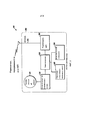
На фиг.1 показана общая схема системы обнаружения, генерирования и передачи надежного оповещения о выходе пользователя из строя согласно настоящему изобретению,Figure 1 shows a General diagram of a system for detecting, generating and transmitting a reliable notification of a user failure according to the present invention,
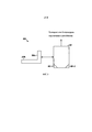
на фиг.2 показана блок-схема детектора согласно настоящему изобретению,figure 2 shows a block diagram of a detector according to the present invention,
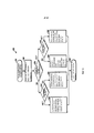
на фиг.3 показана блок-схема центральной станции согласно настоящему изобретению,figure 3 shows a block diagram of a central station according to the present invention,
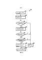
на фиг.4 показана блок-схема способа обнаружения, генерирования и передачи надежного оповещения о выходе пользователя из строя согласно настоящему изобретению,figure 4 shows a block diagram of a method for detecting, generating and transmitting a reliable notification of a user failure according to the present invention,
на фиг.5 показана блок-схема способа отслеживания и мониторинга сигналов тревоги согласно настоящему изобретению и5 is a flowchart of a method for tracking and monitoring alarms according to the present invention, and
на фиг.6 показана блок-схема способа обнаружения сигналов ложной тревоги согласно настоящему изобретению.6 is a flowchart of a method for detecting false alarms according to the present invention.
Описание предпочтительных вариантов осуществленияDescription of Preferred Embodiments
Хотя настоящее изобретение может быть воплощено во множестве различных форм, на чертежах проиллюстрированы и далее подробно описаны конкретные варианты его осуществления, при этом подразумевается, что приведенное описание следует рассматривать как пояснение на примере принципов изобретения. Оно не имеет целью ограничить изобретение конкретными проиллюстрированными вариантами осуществления.Although the present invention can be embodied in many different forms, the drawings illustrate and further describe in detail specific options for its implementation, it is understood that the above description should be considered as an explanation of the principles of the invention. It is not intended to limit the invention to the specific illustrated embodiments.
В вариантах осуществления настоящего изобретения описаны усовершенствованные системы и способы обнаружения, генерирования и передачи надежных оповещений о выходе пользователя из строя. Такие системы и способы способны уменьшать число сигналов ложной тревоги, определять вероятность возникновения события выхода пользователя из строя и генерировать дистанционно передаваемый сигнал тревоги Уменьшение числа сигналов ложной тревоги может достигаться двумя способами. Во-первых, в вариантах осуществления настоящего изобретения может сопоставляться информация, поступающая из нескольких источников. Например, информация, поступающая от датчика перемещения, может сопоставляться с информацией, поступающей от газового и(или) температурного датчика. При сопоставлении этой информации в системах и способах согласно настоящему изобретению предусмотрена возможность определять, существует ли вероятность события выхода пользователя из строя до того, как генерируется сигнал тревоги.In embodiments of the present invention, improved systems and methods for detecting, generating, and transmitting reliable alerts of a user's failure are described. Such systems and methods are able to reduce the number of false alarms, determine the likelihood of a user failure event and generate a remotely transmitted alarm. There are two ways to reduce the number of false alarms. First, in embodiments of the present invention, information from multiple sources can be matched. For example, information from a motion sensor can be compared with information from a gas and / or temperature sensor. When comparing this information, the systems and methods of the present invention provide the ability to determine whether there is a likelihood of a user failure event before an alarm is generated.
Во-вторых, в вариантах осуществления настоящего изобретения детектор может обладать способностью поддержания двусторонней связи. При обнаружении детектором отсутствия перемещения в системах и способах согласно настоящему изобретению предусмотрена возможность передачи оповещения об отсутствии перемещения в удаленный пункт. Затем удаленный пункт может передавать детектору ответное сообщение с целью выяснить состояние здоровья пользователя детектора. Если в ответ получено сообщение, в котором указано, что пользователь не находится в опасности, в системах и способах согласно настоящему изобретению предусмотрена возможность устанавливать, что обнаружен сигнал ложной тревоги. Тем не менее, если в ответ не получено сообщение, в котором указано, что пользователь не находится в опасности, в системах и способах согласно настоящему изобретению предусмотрена возможность устанавливать, что существует вероятность события выхода пользователя из строя, и передача соответствующей команды аварийной спасательной бригаде.Secondly, in embodiments of the present invention, the detector may have the ability to maintain two-way communication. When the detector detects a lack of movement in the systems and methods according to the present invention, it is possible to transmit a notification of the absence of movement to a remote location. Then, the remote site may transmit a response message to the detector in order to determine the health status of the detector user. If a response is received in which it is indicated that the user is not in danger, the systems and methods of the present invention provide the ability to determine that a false alarm has been detected. However, if the response does not receive a message indicating that the user is not in danger, the systems and methods according to the present invention provide the ability to establish that there is a possibility of a user failure event and the transmission of the appropriate command to the emergency rescue team.
Согласно настоящему изобретению может определяться вероятность события выхода пользователя из строя. Например, может сопоставляться информация, поступающая от множества детекторов, находящихся в одной зоне, чтобы устанавливать обоснованную вероятность события выхода пользователя из строя. Если по меньшей мере один из детекторов из множества детекторов, находящихся в одной зоне, обнаруживает отсутствие перемещения в течение заданного времени, и, если все, преимущественно все, большинство или даже один из детекторов обнаруживает высокий уровень содержания опасного газа, в системах и способах согласно настоящему изобретению предусмотрена возможность устанавливать, что существует обоснованная вероятность события выхода пользователя из строя.According to the present invention, the probability of a user failure event can be determined. For example, information from multiple detectors located in the same zone can be matched to establish the reasonable likelihood of a user failure event. If at least one of the detectors from a plurality of detectors located in one zone detects a lack of movement for a given time, and if all, mainly all, the majority or even one of the detectors detects a high level of hazardous gas, in systems and methods according to the present invention provides the ability to establish that there is a reasonable likelihood of a user failure event.
Аналогичным образом, если один детектор обнаруживает отсутствие перемещения в течение заданного времени, а все остальные детекторы в этой зоне регистрируют нормальное перемещение, и при этом не обнаружен опасный газ, в системах и способах согласно настоящему изобретению предусмотрена возможность устанавливать, что пользователь одного детектора просто неподвижно сидит, а не находится без сознания или иным способом выведен из строя. В этих условиях в системах и способах согласно настоящему изобретению предусмотрена возможность устанавливать, что оповещение о выходе пользователя из строя является неадекватным.Similarly, if one detector detects no movement within a predetermined time, and all other detectors in this zone detect normal movement, and no dangerous gas is detected, the systems and methods of the present invention provide the ability to establish that the user of one detector is simply stationary sits, but is not unconscious or otherwise incapacitated. Under these conditions, the systems and methods according to the present invention provide the ability to establish that the notification of a user failure is inadequate.
Согласно настоящему изобретению также может генерироваться дистанционно передаваемый сигнал тревоги. Например, детектор согласно настоящему изобретению может поддерживать связь с центральной станцией. Когда центральная станция принимает сообщение о том, что пользователь детектора находится без сознания или иным способом выведен из строя, и устанавливает отсутствие сигнала ложной тревоги, центральная станция может передать аварийной спасательной бригаде команду оказать помощь пользователю. Аналогичным образом, когда центральная станция принимает сообщение о том, что существует вероятность события выхода пользователя из строя, центральная станция может передать соответствующую команду аварийной бригаде. На фиг.1 показана общая схема системы 100 обнаружения, генерирования и передачи надежного оповещения о выходе пользователя из строя согласно настоящему изобретению. Как показано фиг.1, в систему 100 согласно настоящему изобретению может входить по меньшей мере один детектор 110 и центральная станция 140. В систему может входить один или множество детекторов 110, например 110а и 110b. В вариантах осуществления настоящего изобретения детекторами 110 могут являться детекторы газа или любой другой детектор, известный и требуемый специалисту в данной области техники. Например, детекторами 110 могут являться детекторы дыма или сигнализаторы пожара.A remotely transmitted alarm can also be generated according to the present invention. For example, a detector according to the present invention may communicate with a central station. When the central station receives a message that the detector user is unconscious or otherwise incapacitated, and detects the absence of a false alarm, the central station may instruct the emergency rescue team to assist the user. Similarly, when the central station receives a message stating that there is a possibility of a user failure event, the central station may transmit the appropriate command to the emergency team. 1 shows a general diagram of a
В дополнительных вариантах осуществления настоящего изобретения детекторы 110 могут являться беспроводными или проводными. Например, как показано на фиг.1, когда детекторы 110, 110a, 110b являются беспроводными, детекторы 110, 110a, 110b способны поддерживать связь с центральной станцией 140 посредством инфраструктуры сети беспроводной связи с точками 120, 120а, 120b доступа и глобальной вычислительной сети (ГВС) или локальной вычислительной сети (ЛВС), такой как, например, сеть Ethernet 130. Беспроводные детекторы 110, 110а, 110b способны поддерживать связь с точками 120, 120а, 120b беспроводного доступа, посредством, например, радиосигналов.In further embodiments of the present invention, the
Центральная станция 140 может содержать хост-компьютер, например персональный компьютер, и способна принимать информацию, поступающую от детекторов 110, 110а, 110b. В вариантах осуществления настоящего изобретения центральная станция 140 может иметь программируемый процессор и соответствующую схему управления для выполнения программного обеспечения, хранящегося на локальном машиночитаемом носителе, как это известно специалистам в данной области техники. На фиг.2 показана блок-схема детектора 200 согласно настоящему изобретению. Как показано на фиг.2, детектором 200 является беспроводной детектор газа. Тем не менее, как пояснено выше, настоящее изобретение не ограничено такими детекторами. Детектор 200 может иметь газочувствительный элемент 210, схему 220 запуска датчика и формирования сигнала, микроконтроллер 230, подсистему 240 сигнализации с дисплеем и кнопкой, датчик 250 ускорения или перемещения, модуль 260 радиосвязи и антенну 270. Модуль 260 радиосвязи способен поддерживать радиосвязь любым числом способов, таких как, например, Wi-Fi, ISA100, GPRS, EDGE, 3G, 4G, прямая связь на частоте 900 МГц, WAN и т.п. Каждый из этих компонентов может помещаться в корпусе 280. В некоторых вариантах осуществления из корпуса 280 может выступать по меньшей мере часть антенны 270.The
Согласно настоящему изобретению газочувствительный элемент 210 способен обнаруживать присутствие заданного газа или газов в окружающей атмосфере. Например, газочувствительный элемент 210 способен обнаруживать, что количество опасного газа в окружающей атмосфере достигло заданного предела. При выполнении заданных условий газочувствительный элемент 210 способен передавать сигнал схеме 220 запуска датчика и формирования сигнала 220, которая способна передавать сигнал микроконтроллеру 230. Если принимаемый сигнал указывает на присутствие заданного газа в окружающей атмосфере или указывает, что количество опасного газа в окружающей атмосфере достигло заданного предела, микроконтроллер 230 способен генерировать сигнал газоопасности. Затем микроконтроллер 230 способен передавать сигнал газоопасности модулю 260 радиосвязи, после чего сигнал газоопасности может быть передан посредством антенны 270. Например, антенна 270 способна передавать сигнал газоопасности центральной станции мониторинга. Подсистема 240 сигнализации с дисплеем и кнопкой способна принимать данные, поступающие от пользователя детектора 200.According to the present invention, the
В вариантах осуществления настоящего изобретения датчик 250 ускорения или перемещения 250 способен обнаруживать перемещение детектора 200 и, соответственно, соответствующее перемещение пользователя детектора 200. Когда датчик 250 обнаруживает, что пользователь не перемещается в течение заданного времени, датчик 250 способен передавать сигнал микроконтроллеру 230, а микроконтроллер 230 способен генерировать сигнал оповещения о выходе пользователя из строя. Затем микроконтроллер 230 способен передавать сигнал оповещения о выходе пользователя из строя модулю 260 радиосвязи, после чего сигнал оповещения о выходе пользователя из строя может быть передан посредством антенны 270. Например, антенна 270 способна передавать сигнал оповещения о выходе пользователя из строя центральной станции мониторинга.In embodiments of the present invention, the acceleration or
На фиг.3 показана блок-схема центральной станции 300 согласно настоящему изобретению. Центральная станция 300 способна поддерживать связь с удаленными детекторами и принимать от них информацию.Figure 3 shows a block diagram of a
Как показано на фиг.3, центральная станция 300 может иметь блок 310 управления, который способен поддерживать проводную или беспроводную связь с детекторами посредством глобальной вычислительной сети (ГВС) или локальной вычислительная сеть (ЛВС), такой как, например, сеть Ethernet. Блок 310 управления может быть оснащен одним или несколькими программируемыми процессорами 310-1 и выполняемым программным обеспечением 310-2 системы управления, как это известно специалистам в данной области техники.As shown in FIG. 3, the
Центральная станция 300 также может иметь компьютеризованный дисплей 310а и одно или несколько устройство 310b ввода, которые могут включать во всех случаях без ограничения клавиатуры, шаровые манипуляторы и т.п. Блок 310 управления способен поддерживать связь с пользователем, находящимся на центральной станции 310, посредством дисплея 320а и графического интерфейса пользователя, которые способны предоставлять ситуационную информацию пользователю и принимать информацию от пользователя.The
Центральная станция 300 способна использовать информацию, принимаемую от детектора, несколькими способами. Например, центральная станция 300 может информировать пользователя, находящегося на центральной станции 300, о том, что детектор генерировал сигнал, например сигнал газоопасности или сигнал оповещения о выходе пользователя из строя. Находящийся на центральной станции 300 пользователь может попытаться связаться с удаленным пользователем детектора, чтобы установить, находится ли пользователь в бедственном положении, или установить, следует ли инициировать спасательную операцию. В вариантах осуществления настоящего изобретения для проведения спасательной операции не требуется, чтобы удаленный пользователь детектора был в сознании или был способен предпринимать какое-либо действие.The
Центральная станция 300 также может использовать информацию, принимаемую от детектора, для определения местоположения детектора, генерирующего сигнал. Поскольку системы и способы определения местоположения удаленного устройства известны из техники, они не будут подробно описываться. Тем не менее, подразумевается, что центральная станция 300 способна определять местоположение детектора на основании информации, передаваемой детектором центральной станции 300.The
Кроме того, центральная станция 300 также может использовать информацию, принимаемую от детектора, для определения соответствующего плана действий с учетом обстоятельств. Например, центральная станция 300 может принимать от детектора сведения о местонахождении, а также информацию, касающуюся сигналов газоопасности и сигналов оповещения о выходе пользователя из строя. Центральная станция 300 может использовать эту информацию, чтобы устанавливать вероятность присутствия опасного газа и вероятность того, что пользователь детектора находится без сознания. Центральная станция 300 также может использовать эту информацию, чтобы генерировать сигналы газоопасности и(или) сигналы оповещения о выходе пользователя из строя и обнаруживать сигналы ложной тревоги. Способы, которым это осуществляется, проиллюстрированы на фиг.5 и 6, и будут более подробно описаны далее.In addition, the
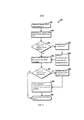
На фиг.4 показана блок-схема способа 400 обнаружения, генерирования и передачи надежного оповещения о выходе пользователя из строя согласно настоящему изобретению. В вариантах осуществления настоящего изобретения способ 400 может выполнять детектор, например, детектор 200, показанный на фиг.2.FIG. 4 is a flow diagram of a
Способ 400 может выполняться с заданными постоянными интервалами, необходимыми для обнаружения присутствия опасного газа. Например, способ 400 может выполняться один раз в секунду.
На шаге 410 способа 400 может цикл проверки сигнала тревоги и оповещения, а на шаге 420 на основе показаний датчика газа и схемы формирования сигнала может определяться уровень содержания газа. Затем на шаге 430 способа 400 может устанавливаться, превышает ли уровень содержания газа порог срабатывания устройства сигнализации. Например, порогом срабатывания устройства сигнализации может являться содержание H2S, составляющее 10 ч./млн. Если уровень содержания газа не превышает порог срабатывания устройства сигнализации, на шаге 460 могут считываться показания датчика ускорения и проверяться наличие перемещения. Тем не менее, если уровень содержания газа превышает порог срабатывания устройства сигнализации, на шаге 440 может генерироваться локальный сигнал газоопасности, который на шаге 450 может передаваться центральной станции. Например, сигнал газоопасности может передаваться удаленному персональному компьютеру, который контролирует и отслеживает местоположение. В вариантах осуществления настоящего изобретения сигнал газоопасности может передаваться от детектора посредством радиосигналов.At
После того, как центральную станцию на шаге 450 оповещают о сигнале газоопасности, на шаге 460 могут считываться показания датчика ускорения и проверяться наличие перемещения. Затем на шаге 470 способа 400 может устанавливаться, перемещался ли пользователь в течение заданного времени. Например, заданное время может составлять 120 секунд. Если пользователь перемещался в течение заданного времени, на шаге 495 способа 400 может завершаться цикл проверки сигнала тревоги и оповещения.After the central station is notified of a gas hazard signal in
Тем не менее, если пользователь не перемещался в течение заданного времени, на шаге 480 может генерироваться локальный сигнал оповещения о выходе пользователя из строя, который на шаге 490 может передаваться центральной станции. Например, сигнал оповещения о выходе пользователя из строя может передаваться удаленному персональному компьютеру, который контролирует и отслеживает местоположение. В вариантах осуществления настоящего изобретения сигнал оповещения о выходе пользователя из строя может передаваться от детектора посредством радиосигналов.Nevertheless, if the user did not move for a predetermined time, at step 480 a local alert signal can be generated indicating the user's failure, which at step 490 can be transmitted to the central station. For example, a warning signal about a user's failure can be transmitted to a remote personal computer that monitors and tracks the location. In embodiments of the present invention, a user failure alert may be transmitted from the detector via radio signals.
После передачи сигнала оповещения о выходе пользователя из строя на шаге 495 способа 400 может завершаться цикл проверки сигнала тревоги и оповещения и на шаге 410 снова начинаться цикл проверки сигнала тревоги и оповещения.After the user is notified of the failure of the signal at
На фиг.5 показана блок-схема способа 500 отслеживания и мониторинга сигналов тревоги согласно настоящему изобретению. В вариантах осуществления настоящего изобретения способ 500 способна выполнять центральная станция, например, центральная станция 140, показанная на фиг.1, или центральная станция 300, показанная на фиг.3.5 is a flowchart of a
Как пояснено выше, центральная станция 140 или 300 может иметь программируемые процессоры и выполняемое программное обеспечение системы управления. В вариантах осуществления настоящего изобретения процессоры, программное обеспечение и любая соответствующая схема управления способны отслеживать местоположение соответствующих детекторов, например беспроводных детекторов газа, и осуществлять мониторинг передаваемой ими информации.As explained above, the
На шаге 510 способа 500 может начинаться обработка сигнала оповещения о выходе пользователя из строя и сигнала газоопасности, а на шаге 520 из детектора газа может быть извлечен пакет вызывающих сигнал тревоги событий. Затем на шаге 530 способа 500 может устанавливаться, содержится ли в пакете вызывающих сигнал тревоги событий сигнал газоопасности.At
Если на шаге 530 способа 500 установлено, что в пакете вызывающих сигнал тревоги событий содержится сигнал газоопасности, способ 500 может перейти к шагу 540, на котором устанавливается, содержится ли в пакете вызывающих сигнал тревоги событий сигнал оповещения о выходе пользователя из строя. Тем не менее, если на шаге 530 способа 500 установлено, что в пакете вызывающих сигнал тревоги событий не содержится сигнал газоопасности, способ 500 может перейти к шагу 550, на котором устанавливается, содержится ли в пакете вызывающих сигнал тревоги событий сигнал оповещения о выходе пользователя из строя. Отличие шага 540, на котором устанавливается, содержится ли в пакете вызывающих сигнал тревоги событий сигнал оповещения о выходе пользователя из строя, от шага 550, на котором устанавливается, содержится ли в пакете вызывающих сигнал тревоги событий сигнал оповещения о выходе пользователя из строя, заключается в последующих шагах способа 500.If it is determined at
Если на шаге 540 способа 500 установлено, что в пакете вызывающих сигнал тревоги событий не содержится сигнал оповещения о выходе пользователя из строя, на шаге 560 способа 500 может устанавливаться, что имело место воздействие газа, но пользователь не находится без сознания или иным способом выведен из строя. На шаге 560 способа 500 также может устанавливаться, что, вероятно, имело место самоспасание, и может генерироваться сигнал тревоги, указывающий на присутствие опасного газа. Затем на шаге 595 способа может завершаться обработка сигнала оповещения о выходе пользователя из строя и сигнала газоопасности.If it is determined in
Если на шаге 540 способа 500 установлено, что в пакете вызывающих сигнал тревоги событий содержится сигнал оповещения о выходе пользователя из строя, на шаге 570 способа 500 может устанавливаться, что имело место воздействие газа, и что пользователь находится без сознания или иным способом выведен из строя. На шаге 570 также может генерироваться один или несколько сигналов тревоги, указывающих на присутствие опасного газа и на то, что пользователь выведен из строя. Затем на шаге 595 способа может завершаться обработка сигнала оповещения о выходе пользователя из строя и сигнала газоопасности.If it is determined in
Если на шаге 550 способа 500 установлено, что в пакете вызывающих сигнал тревоги событий содержится сигнал оповещения о выходе пользователя из строя, на шаге 580 может устанавливаться, что опасный газ не присутствует, но пользователь находится без сознания или иным способом выведен из строя. На шаге 580 также может генерироваться сигнал тревоги, указывающий, что пользователь выведен из строя. Затем на шаге 595 способа может завершаться обработка сигнала оповещения о выходе пользователя из строя и сигнала газоопасности.If it is determined in step 550 of
Если на шаге 550 способа 500 установлено, что в пакете вызывающих сигнал тревоги событий не содержится сигнал оповещения о выходе пользователя из строя, на шаге 590 может устанавливаться, что имело место какое-либо иное вызывающее сигнал тревоги событие. Затем на шаге 595 способа может завершаться обработка сигнала оповещения о выходе пользователя из строя и сигнала газоопасности.If it is determined in step 550 of
На фиг.6 показана блок-схема способа 600 обнаружения сигналов ложной тревоги согласно настоящему изобретению. В вариантах осуществления настоящего изобретения способ 600 может выполнять центральная станция, например, центральная станция 140, показанная на фиг.1, или центральная станция 300, показанная на фиг.3.6 is a flowchart of a
На шаге 610 способ 600 может начинаться с обнаружения сигнала ложной тревоги, а на шаге 620 от первого детектора может быть принят сигнал оповещения о выходе пользователя из строя. Затем на шаге 630 способа 600 может устанавливаться, содержится ли сигнал газоопасности в пакете вызывающих сигнал тревоги событий, принятом от первого детектора.At
Если на шаге 630 способа 600 установлено, что в пакете вызывающих сигнал тревоги событий, принятом от первого детектора, содержится сигнал газоопасности, на шаге 680 может генерироваться сигнал тревоги, и на шаге 690 способа 600 может завершаться обнаружение сигнала ложной тревоги.If it is determined in
Тем не менее, если на шаге 630 способа 600 установлено, что в пакете вызывающих сигнал тревоги событий, принятом от первого детектора, не содержится сигнал газоопасности, на шаге 640 может быть проверено множество других детекторов вблизи первого детектора. Затем на шаге 650 способа 600 может быть установлено, содержатся ли сигналы газоопасности в пакетах вызывающих сигнал тревоги событий, принятых от множества других детекторов.However, if it was determined at
Если на шаге 650 способа 600 установлено, что в пакетах вызывающих сигнал тревоги событий, принятых от множества других детекторов, содержатся сигналы газоопасности, на шаге 680 может генерироваться сигнал тревоги 680, и на шаге 690 способа 600 может завершаться обработка обнаруженного сигнала ложной тревоги. Тем не менее, если на шаге 650 способа 600 установлено, что в пакетах вызывающих сигнал тревоги событий, принятых от множества других детекторов, не содержатся сигналы газоопасности, на шаге 660 способа 600 может устанавливаться, содержатся ли сигналы оповещения о выходе пользователя из строя в пакетах вызывающих сигнал тревоги событий, принятых от множества других детекторов.If it is determined in
Если на шаге 660 способа 600 установлено, что в пакетах вызывающих сигнал тревоги событий, принятых от множества других детекторов, содержатся сигналы оповещения о выходе пользователя из строя, на шаге 680 может генерироваться сигнал тревоги, и на шаге 690 способа 600 может завершаться обработка обнаруженного сигнала ложной тревоги. Тем не менее, если на шаге 660 способа 600 установлено, что в пакетах вызывающих сигнал тревоги событий, принятых от множества других детекторов, не содержатся сигналы оповещения о выходе пользователя из строя, может устанавливаться, что сигнал оповещения о выходе пользователя из строя, принятый от первого детектора на шаге 620 способа 600, является ложным. На шаге 670 способа может передаваться предупреждение о сигнале ложной тревоги или просто игнорироваться сигнал ложной тревоги. Затем на шаге 690 способа 600 может завершаться обработка обнаруженного сигнала ложной тревоги.If it is determined at
В вариантах осуществления настоящего изобретения способ 600, проиллюстрированный на фиг.6, может выполняться всякий раз, когда от детектора принимается сигнал оповещения о выходе пользователя из строя. Например, когда центральная станция 140 принимает сигнал оповещения о выходе пользователя из строя от любого детектора 110, 110а, 110b в системе 100, центральная станция 140 может выполнять способ 600, чтобы определять, является ли сигнал сигналом ложной тревоги.In embodiments of the present invention, the
При анализе на шагах 640, 650 и 660 пакетов вызывающих сигнал тревоги событий, поступающих от множества других детекторов вблизи первого детектора, могут анализироваться данные некоторых или всех из множества других детекторов вблизи первого детектора. Например, в вариантах осуществления настоящего изобретения могут анализироваться данные всех, преимущественно всех или даже одного из множества других детекторов.When analyzing at
В некоторых вариантах осуществления все, преимущественно все, большинство или только один из множества других детекторов должен передавать пакет вызывающих сигнал тревоги событий, содержащий сигнал газоопасности, позволяющий на шаге 650 способа 600 обнаруживать присутствие сигналов газоопасности в данных, поступающих от множества других детекторов. Аналогичным образом в некоторых вариантах осуществления все, преимущественно все, большинство или только один из множества других детекторов должен передавать пакет вызывающих сигнал тревоги событий, содержащий сигнал оповещения о выходе пользователя из строя, позволяющий на шаге 660 способа 600 обнаруживать присутствие сигналов оповещения о выходе пользователя из строя, в данных, поступающих от множества других детекторов.In some embodiments, all, predominantly all, most, or only one of the many other detectors must transmit an alarm-triggering packet containing a gas hazard signal, allowing
Хотя выше было подробно описано несколько вариантов осуществления, возможны другие их разновидности. Например, в блок-схемах, представленных на чертежах, не обязательна конкретная показанная очередность или последовательность шагов для достижения желаемых результатов. Могут быть предусмотрены другие шаги, или из описанных блок-схем могут быть исключены шаги, а в описанные системы могут быть добавлены другие компоненты или из них могут быть исключены компоненты. Возможны другие варианты осуществления, не выходящие за пределы объема следующей далее формулы изобретения.Although several embodiments have been described in detail above, other variations are possible. For example, in the flowcharts shown in the drawings, the particular order shown or sequence of steps is not necessary to achieve the desired results. Other steps may be provided, or steps may be omitted from the described flowcharts, and other components may be added to the described systems, or components may be excluded from them. Other embodiments are possible without departing from the scope of the following claims.
Из вышесказанного следует, что могут быть предложены многочисленные разновидности и модификации, не выходящие за пределы существа объема изобретения. Подразумевается, что изобретение не ограничено конкретной проиллюстрированной в нем системой или способом. Разумеется, что все такие модификации, входящие охраняются прилагаемой формулой изобретения, если они входят в пределы объема и существа формулы изобретения.From the foregoing it follows that can be offered numerous varieties and modifications that do not go beyond the essence of the scope of the invention. It is understood that the invention is not limited to the specific system or method illustrated therein. Of course, all such modifications included are protected by the attached claims, if they fall within the scope and essence of the claims.
Claims (32)
Applications Claiming Priority (2)
| Application Number | Priority Date | Filing Date | Title |
|---|---|---|---|
| US13/015,327 US10685554B2 (en) | 2011-01-27 | 2011-01-27 | Systems and methods for robust man-down alarms |
| US13/015,327 | 2011-01-27 |
Publications (2)
| Publication Number | Publication Date |
|---|---|
| RU2012103389A RU2012103389A (en) | 2013-08-10 |
| RU2606236C2 true RU2606236C2 (en) | 2017-01-10 |
Family
ID=45495859
Family Applications (1)
| Application Number | Title | Priority Date | Filing Date |
|---|---|---|---|
| RU2012103389A RU2606236C2 (en) | 2011-01-27 | 2012-02-01 | Systems and methods for robust man-down alarms |
Country Status (8)
| Country | Link |
|---|---|
| US (3) | US10685554B2 (en) |
| EP (2) | EP3734563B1 (en) |
| JP (1) | JP5788339B2 (en) |
| CN (1) | CN102622853B (en) |
| BR (1) | BR102012001686A2 (en) |
| CA (1) | CA2765328C (en) |
| IN (1) | IN2012DE00219A (en) |
| RU (1) | RU2606236C2 (en) |
Cited By (3)
| Publication number | Priority date | Publication date | Assignee | Title |
|---|---|---|---|---|
| WO2018063135A1 (en) * | 2016-09-29 | 2018-04-05 | Андрий Володымыровыч СУЛЫМ | System for preventing the onset of emergency situations in utility systems of premises |
| RU2695499C1 (en) * | 2018-12-03 | 2019-07-23 | Общество с ограниченной ответственностью "СМАРТЛАЙН" | Method and device for remote monitoring of compliance with safety regulations by employees |
| US10685554B2 (en) | 2011-01-27 | 2020-06-16 | Honeywell International Inc. | Systems and methods for robust man-down alarms |
Families Citing this family (12)
| Publication number | Priority date | Publication date | Assignee | Title |
|---|---|---|---|---|
| US9251687B2 (en) | 2013-04-19 | 2016-02-02 | Jonathan Thompson | Global positioning system equipped hazard detector and a system for providing hazard alerts thereby |
| US9159206B2 (en) | 2013-05-30 | 2015-10-13 | Motorola Solutions, Inc. | Method and apparatus for locating a person during a man-down situation |
| DE102014204158B4 (en) * | 2014-03-06 | 2018-12-13 | Msa Europe Gmbh | Mobile monitor |
| US9269252B2 (en) * | 2014-04-17 | 2016-02-23 | Honeywell International Inc. | Man down detector |
| GB2525903A (en) * | 2014-05-08 | 2015-11-11 | Monitorgo Ltd | A device for determining unconciousness of a subject and a device for detecting a fall by a subject |
| US10328292B2 (en) * | 2014-08-27 | 2019-06-25 | Honeywell International Inc. | Multi-sensor based motion sensing in SCBA |
| US9934672B2 (en) * | 2015-09-24 | 2018-04-03 | Honeywell International Inc. | Systems and methods of conserving battery life in ambient condition detectors |
| US10593164B2 (en) | 2015-11-09 | 2020-03-17 | Honeywell International Inc. | Aggregate monitor data in real-time by worker |
| WO2018049580A1 (en) * | 2016-09-14 | 2018-03-22 | Honeywell International Inc. | Over the air modem firmware upgrade based on mesh network |
| CN108564775A (en) * | 2018-06-06 | 2018-09-21 | 天津市天安博瑞科技有限公司 | Alarm method and system of distress call device and electronic equipment |
| US11176799B2 (en) | 2019-09-10 | 2021-11-16 | Jonathan Thompson | Global positioning system equipped with hazard detector and a system for providing hazard alerts thereby |
| WO2022149095A1 (en) * | 2021-01-11 | 2022-07-14 | 3M Innovative Properties Company | Device, system, and method for providing a notification |
Citations (10)
| Publication number | Priority date | Publication date | Assignee | Title |
|---|---|---|---|---|
| US4468656A (en) * | 1981-06-24 | 1984-08-28 | Clifford Thomas J | Emergency signalling unit and alarm system for rescuing endangered workers |
| US5045839A (en) * | 1990-03-08 | 1991-09-03 | Rand G. Ellis | Personnel monitoring man-down alarm and location system |
| US6121881A (en) * | 1994-09-02 | 2000-09-19 | Safety Tech Industries, Inc. | Protective mask communication devices and systems for use in hazardous environments |
| US20040021569A1 (en) * | 2001-11-21 | 2004-02-05 | Robert Lepkofker | Personnel and resource tracking method and system for enclosed spaces |
| WO2007057692A2 (en) * | 2005-11-18 | 2007-05-24 | Lusora Limited | Detection of a person falling |
| US20080061962A1 (en) * | 2006-09-06 | 2008-03-13 | Grace Industries, Inc. | Automated accountability locating system |
| RU72778U1 (en) * | 2007-12-20 | 2008-04-27 | Али Николаевич Любенко | MOBILE SIGNALING DEVICE |
| US20080211668A1 (en) * | 2007-03-02 | 2008-09-04 | Dixon Walter V | Method and system to detect humans or animals within confined spaces with a low rate of false alarms |
| US20100081411A1 (en) * | 2008-09-29 | 2010-04-01 | John Mathew Montenero, III | Multifunctional telemetry alert safety system (MTASS) |
| RU2401947C2 (en) * | 2009-01-16 | 2010-10-20 | Андрей Викторович Демидюк | Underground system of monitoring, annunciation and determination of mine worker location |
Family Cites Families (23)
| Publication number | Priority date | Publication date | Assignee | Title |
|---|---|---|---|---|
| JPS5776685A (en) | 1980-10-31 | 1982-05-13 | Tokyo Shibaura Electric Co | Warning system |
| US4665385A (en) * | 1985-02-05 | 1987-05-12 | Henderson Claude L | Hazardous condition monitoring system |
| US4747120A (en) * | 1985-08-13 | 1988-05-24 | Digital Products Corporation | Automatic personnel monitoring system |
| JPH0373096A (en) | 1989-08-12 | 1991-03-28 | Matsushita Electric Works Ltd | Fire sensor |
| JPH06180790A (en) | 1992-12-14 | 1994-06-28 | Fujitsu Denso Ltd | Security system |
| DE4329898A1 (en) * | 1993-09-04 | 1995-04-06 | Marcus Dr Besson | Wireless medical diagnostic and monitoring device |
| US5483222A (en) | 1993-11-15 | 1996-01-09 | Pittway Corporation | Multiple sensor apparatus and method |
| JPH08315277A (en) | 1995-05-16 | 1996-11-29 | Nippon Denki Ido Tsushin Kk | Portable gas detection and informing device |
| JPH1011686A (en) | 1996-06-27 | 1998-01-16 | Matsushita Electric Works Ltd | Abnormality detector |
| US6199550B1 (en) * | 1998-08-14 | 2001-03-13 | Bioasyst, L.L.C. | Integrated physiologic sensor system |
| US6023223A (en) * | 1999-03-18 | 2000-02-08 | Baxter, Jr.; John Francis | Early warning detection and notification network for environmental conditions |
| JP2000339571A (en) | 1999-05-28 | 2000-12-08 | Omron Corp | Living management system and sensor used for the system |
| US6847892B2 (en) * | 2001-10-29 | 2005-01-25 | Digital Angel Corporation | System for localizing and sensing objects and providing alerts |
| US6992580B2 (en) * | 2002-07-25 | 2006-01-31 | Motorola, Inc. | Portable communication device and corresponding method of operation |
| US7263379B1 (en) * | 2002-12-23 | 2007-08-28 | Sti Licensing Corp. | Communications network for emergency services personnel |
| US20060282021A1 (en) * | 2005-05-03 | 2006-12-14 | Devaul Richard W | Method and system for fall detection and motion analysis |
| US7932809B2 (en) * | 2006-02-23 | 2011-04-26 | Rockwell Automation Technologies, Inc. | RFID/biometric area protection |
| JP2008015659A (en) | 2006-07-04 | 2008-01-24 | Toshiba Corp | Situation detection terminal and situation reporting system using the same |
| JP5046676B2 (en) | 2007-02-15 | 2012-10-10 | Necインフロンティア株式会社 | Home anomaly detection method, apparatus, and program therefor |
| JP5066034B2 (en) | 2008-08-28 | 2012-11-07 | アイホン株式会社 | Apartment house intercom system |
| US8330605B2 (en) * | 2009-08-14 | 2012-12-11 | Accenture Global Services Limited | System for providing real time locating and gas exposure monitoring |
| US10685554B2 (en) | 2011-01-27 | 2020-06-16 | Honeywell International Inc. | Systems and methods for robust man-down alarms |
| US8665097B2 (en) | 2011-05-10 | 2014-03-04 | Honeywell International Inc. | System and method of worker fall detection and remote alarm notification |
-
2011
- 2011-01-27 US US13/015,327 patent/US10685554B2/en active Active
-
2012
- 2012-01-20 EP EP20165730.1A patent/EP3734563B1/en active Active
- 2012-01-20 EP EP12152018.3A patent/EP2482264B1/en active Active
- 2012-01-20 CA CA2765328A patent/CA2765328C/en active Active
- 2012-01-22 CN CN201210063759.5A patent/CN102622853B/en active Active
- 2012-01-23 JP JP2012011221A patent/JP5788339B2/en not_active Expired - Fee Related
- 2012-01-25 BR BRBR102012001686-9A patent/BR102012001686A2/en not_active Application Discontinuation
- 2012-01-25 IN IN219DE2012 patent/IN2012DE00219A/en unknown
- 2012-02-01 RU RU2012103389A patent/RU2606236C2/en active
-
2020
- 2020-05-26 US US16/883,582 patent/US11276297B2/en active Active
-
2022
- 2022-02-02 US US17/590,999 patent/US11842620B2/en active Active
Patent Citations (10)
| Publication number | Priority date | Publication date | Assignee | Title |
|---|---|---|---|---|
| US4468656A (en) * | 1981-06-24 | 1984-08-28 | Clifford Thomas J | Emergency signalling unit and alarm system for rescuing endangered workers |
| US5045839A (en) * | 1990-03-08 | 1991-09-03 | Rand G. Ellis | Personnel monitoring man-down alarm and location system |
| US6121881A (en) * | 1994-09-02 | 2000-09-19 | Safety Tech Industries, Inc. | Protective mask communication devices and systems for use in hazardous environments |
| US20040021569A1 (en) * | 2001-11-21 | 2004-02-05 | Robert Lepkofker | Personnel and resource tracking method and system for enclosed spaces |
| WO2007057692A2 (en) * | 2005-11-18 | 2007-05-24 | Lusora Limited | Detection of a person falling |
| US20080061962A1 (en) * | 2006-09-06 | 2008-03-13 | Grace Industries, Inc. | Automated accountability locating system |
| US20080211668A1 (en) * | 2007-03-02 | 2008-09-04 | Dixon Walter V | Method and system to detect humans or animals within confined spaces with a low rate of false alarms |
| RU72778U1 (en) * | 2007-12-20 | 2008-04-27 | Али Николаевич Любенко | MOBILE SIGNALING DEVICE |
| US20100081411A1 (en) * | 2008-09-29 | 2010-04-01 | John Mathew Montenero, III | Multifunctional telemetry alert safety system (MTASS) |
| RU2401947C2 (en) * | 2009-01-16 | 2010-10-20 | Андрей Викторович Демидюк | Underground system of monitoring, annunciation and determination of mine worker location |
Cited By (5)
| Publication number | Priority date | Publication date | Assignee | Title |
|---|---|---|---|---|
| US10685554B2 (en) | 2011-01-27 | 2020-06-16 | Honeywell International Inc. | Systems and methods for robust man-down alarms |
| US11276297B2 (en) | 2011-01-27 | 2022-03-15 | Honeywell International Inc. | Systems and methods for robust man-down alarms |
| US11842620B2 (en) | 2011-01-27 | 2023-12-12 | Honeywell International Inc. | Systems and methods for robust man-down alarms |
| WO2018063135A1 (en) * | 2016-09-29 | 2018-04-05 | Андрий Володымыровыч СУЛЫМ | System for preventing the onset of emergency situations in utility systems of premises |
| RU2695499C1 (en) * | 2018-12-03 | 2019-07-23 | Общество с ограниченной ответственностью "СМАРТЛАЙН" | Method and device for remote monitoring of compliance with safety regulations by employees |
Also Published As
| Publication number | Publication date |
|---|---|
| US10685554B2 (en) | 2020-06-16 |
| EP3734563A1 (en) | 2020-11-04 |
| EP3734563B1 (en) | 2023-10-11 |
| JP2012155724A (en) | 2012-08-16 |
| US20220189284A1 (en) | 2022-06-16 |
| EP2482264A3 (en) | 2015-06-10 |
| US11842620B2 (en) | 2023-12-12 |
| CN102622853A (en) | 2012-08-01 |
| EP2482264A2 (en) | 2012-08-01 |
| US20120194334A1 (en) | 2012-08-02 |
| JP5788339B2 (en) | 2015-09-30 |
| US11276297B2 (en) | 2022-03-15 |
| CA2765328A1 (en) | 2012-07-27 |
| IN2012DE00219A (en) | 2015-06-19 |
| CA2765328C (en) | 2020-12-15 |
| CN102622853B (en) | 2016-09-07 |
| EP2482264B1 (en) | 2020-04-01 |
| RU2012103389A (en) | 2013-08-10 |
| BR102012001686A2 (en) | 2015-06-30 |
| US20200357264A1 (en) | 2020-11-12 |
Similar Documents
| Publication | Publication Date | Title |
|---|---|---|
| RU2606236C2 (en) | Systems and methods for robust man-down alarms | |
| EP2905760B1 (en) | System and method for location tagged headcount accounting | |
| US8665097B2 (en) | System and method of worker fall detection and remote alarm notification | |
| KR100846829B1 (en) | System for monitoring industrial disaster in the manufacturing industry | |
| KR101755533B1 (en) | Safety management system based on Internet of Things | |
| US8818713B2 (en) | System and apparatus providing localized evacuation guidance | |
| CA2855484C (en) | Method to detect an alarm situation and to send silent alerts to external systems using voice input to mobile devices | |
| WO2015057187A1 (en) | Intelligent personnel escape routing during hazard event | |
| CN113838264A (en) | Alarm system and alarm method | |
| US11016189B2 (en) | Systems and methods for security system device tamper detection | |
| CN110222216A (en) | Multifunctional intellectual defence system | |
| EP3109839B1 (en) | Method of implementing gps based extended chime and special escort mode in security panel | |
| Roslan et al. | Advanced gas leakage, fire and power supply failure monitoring system | |
| KR101388984B1 (en) | Alarm system for the lifesaving | |
| KR101378296B1 (en) | System for preventing crime using human body communication and method for preventing crime using human body communication | |
| WO2015004510A1 (en) | A novel safe guard device as insurance for life | |
| CN117334014A (en) | Personnel state detection method, system, device, storage medium and electronic equipment | |
| KR20240063299A (en) | Wearable devices for ships and ports worker safety | |
| CN109903506A (en) | A kind of indoor security detection system |