RU2601739C2 - Bypass system for overhead power lines - Google Patents
Bypass system for overhead power lines Download PDFInfo
- Publication number
- RU2601739C2 RU2601739C2 RU2014154404/07A RU2014154404A RU2601739C2 RU 2601739 C2 RU2601739 C2 RU 2601739C2 RU 2014154404/07 A RU2014154404/07 A RU 2014154404/07A RU 2014154404 A RU2014154404 A RU 2014154404A RU 2601739 C2 RU2601739 C2 RU 2601739C2
- Authority
- RU
- Russia
- Prior art keywords
- bypass system
- outdoor unit
- frame
- housing
- frames
- Prior art date
Links
Images
Classifications
-
- H—ELECTRICITY
- H02—GENERATION; CONVERSION OR DISTRIBUTION OF ELECTRIC POWER
- H02B—BOARDS, SUBSTATIONS OR SWITCHING ARRANGEMENTS FOR THE SUPPLY OR DISTRIBUTION OF ELECTRIC POWER
- H02B1/00—Frameworks, boards, panels, desks, casings; Details of substations or switching arrangements
- H02B1/26—Casings; Parts thereof or accessories therefor
- H02B1/52—Mobile units, e.g. for work sites
-
- H—ELECTRICITY
- H02—GENERATION; CONVERSION OR DISTRIBUTION OF ELECTRIC POWER
- H02G—INSTALLATION OF ELECTRIC CABLES OR LINES, OR OF COMBINED OPTICAL AND ELECTRIC CABLES OR LINES
- H02G1/00—Methods or apparatus specially adapted for installing, maintaining, repairing or dismantling electric cables or lines
- H02G1/02—Methods or apparatus specially adapted for installing, maintaining, repairing or dismantling electric cables or lines for overhead lines or cables
- H02G1/04—Methods or apparatus specially adapted for installing, maintaining, repairing or dismantling electric cables or lines for overhead lines or cables for mounting or stretching
Abstract
Description
ОБЛАСТЬ ТЕХНИКИ, К КОТОРОЙ ОТНОСИТСЯ ИЗОБРЕТЕНИЕFIELD OF THE INVENTION
Данное изобретение относится к байпасной (обходной) системе для воздушных линий электроснабжения.This invention relates to a bypass (bypass) system for overhead power lines.
УРОВЕНЬ ТЕХНИКИBACKGROUND
Воздушная линия электроснабжения - это воздушная линия электропередачи, содержащая один или несколько неизолированных электрических проводов, подвешенных посредством опор или мачт. Поскольку большинство изоляции обеспечивается воздухом, воздушные линии электроснабжения в общем случае являются воплощением обычного способа передачи электрической энергии в больших количествах и поэтому используются главным образом для переноса тока высокого напряжения (ВН) (в типичном случае - свыше 30-35 кВ). Воздушным линиям электроснабжения нужны опоры для поддержания и изоляторы для изоляции конструкции опор (в типичном случае - стальных опор решетчатого типа) от каждого провода воздушной линии электропередачи; концы изолированного кабеля соединены с воздушными линиями электроснабжения на соответствующих оконечных станциях или подстанциях посредством компонентов, именуемых концевыми муфтами, пригодными для обеспечения требуемого перехода от неизолированного провода воздушной линии, изолируемого воздухом, к кабелю, имеющему провод, покрытый слоем изоляции, и заземленный электрический экран.An overhead power supply line is an overhead power line containing one or more bare electrical wires suspended by supports or masts. Since most insulation is provided by air, overhead power lines are generally the embodiment of the conventional method of transferring large amounts of electrical energy and are therefore mainly used to transfer high voltage (HV) current (typically over 30-35 kV). Overhead power lines need supports to support and insulators to isolate the structure of the supports (typically steel grid supports) from each wire of an overhead power line; the ends of the insulated cable are connected to overhead power lines at the respective terminal stations or substations by means of components called end sleeves suitable for providing the required transition from the uninsulated wire of the overhead line insulated by air to a cable having a wire coated with an insulation layer and a grounded electrical shield.
Воздушные линии электроснабжения в типичном случае содержат подстанции как часть системы генерирования, передачи и распределения электрической энергии. Например, подстанции преобразуют напряжение из высокого в низкое, или наоборот, соединяют воздушные линии электроснабжения с кабельными линиями, или выполняют несколько других функций электрической сети.Overhead power lines typically include substations as part of a system for generating, transmitting, and distributing electrical energy. For example, substations convert voltage from high to low, or vice versa, connect overhead power lines to cable lines, or perform several other functions of the electrical network.
Воздушные линии электроснабжения нуждаются в проведении планового и внепланового технического обслуживания, особенно на подстанциях, например: когда происходит модернизация и реконструкция опоры и воздушных линий электроснабжения; когда на подстанции требуется восстановление или расширение; когда силовые трансформаторы, автоматические выключатели, коммутационная аппаратура, шунты или другие компоненты подстанции подлежат замене.Overhead power lines need scheduled and unscheduled maintenance, especially at substations, for example: when there is a modernization and reconstruction of a support and overhead power lines; when a substation requires restoration or expansion; when power transformers, circuit breakers, switching equipment, shunts or other components of a substation must be replaced.
Такие операции проводятся путем отсоединения всех компонентов, вовлеченных в работу по техническому обслуживанию, от линии электропередачи. Чтобы гарантировать непрерывность подачи электрической энергии потребителям в течение периода технического обслуживания, используют временные байпасные системы, которые соединяют точки входа и выхода в пределах подстанций. Как правило, по меньшей мере, один из концов байпасной системы или оба этих конца соединяют с воздушной линией электроснабжения.Such operations are carried out by disconnecting all components involved in the maintenance work from the power line. To guarantee the continuity of the supply of electrical energy to consumers during the maintenance period, temporary bypass systems are used that connect the entry and exit points within the substations. Typically, at least one end of the bypass system, or both of these ends, is connected to an overhead power supply line.
Пример байпасной системы для воздушных линий электроснабжения описан фирмой Silec Cable в публикации HVSBL, январь, 2006 (www.sileccable.com/Portals/france/pdf/en/2151_HVSBL.pdf).An example of a bypass system for overhead power lines is described by Silec Cable in HVSBL, January 2006 (www.sileccable.com/Portals/france/pdf/en/2151_HVSBL.pdf).
В соответствии с этой публикацией, трехфазная система высоковольтных резервных вставок (HVSBL) содержит три отрезка кабеля, снабженные двумя синтетическими концевыми муфтами, заранее смонтированными на заводе-изготовителе, три специализированных барабана, обеспечивающих хранение, транспортировку, а также размотку и повторную намотку упомянутых отрезков, снабженных собственными концевыми муфтами, и шесть металлических конструкций (по выбору) для поддержания концевых муфт во время использования.In accordance with this publication, the three-phase system of high-voltage backup inserts (HVSBL) contains three cable sections equipped with two synthetic end sleeves pre-assembled at the factory, three specialized drums for storage, transportation, as well as unwinding and rewinding of the said sections, equipped with their own end sleeves, and six metal structures (optional) to support the end sleeves during use.
Проиллюстрированные системы вставок, устанавливаемые на специализированных металлических барабанах, приспособлены для содержания и защиты кабеля, оснащенного двумя собственными концевыми муфтами. Трехфазная система вставок может содержать от одного-единственного барабана диаметром 2,6 м с тремя отделениями для установки на одном и том же барабане трех фаз HVSBL, рассчитанной на 90 кВ и имеющей длину 20 м, до трех специальных барабанов по 4,7 м, каждый из которых содержит одну фазу HVSBL, рассчитанной на 225 кВ и имеющей длину 350 м. В общем случае, концевые муфты устанавливают в защитных средствах (в трубе или на фундаментной раме), расположенных и закрепленных на внутренней стороне барабана (для транспортировки). Длина концевой муфты увеличивается с напряжением и может находиться в диапазоне между 1,8 м для 90 кВ и 2,8 м для 225 кВ. Поставляемые барабаны, укладочное оборудование и обычные инструменты транспортируют с помощью грузового автомобиля со складского двора до места установки. Металлическая конструкция, поддерживающая концевые муфты во время работы, может быть металлической конструкцией, обеспечивающей механическое поддержание концевой муфты; каждую концевую муфту поднимают краном, располагая ее поверх соответствующей металлической конструкции и механически сочленяя с ней.The illustrated insertion systems mounted on specialized metal drums are adapted to contain and protect a cable equipped with two own end sleeves. The three-phase insert system can contain from a single drum with a diameter of 2.6 m with three compartments for installation on the same drum of three phases HVSBL, designed for 90 kV and having a length of 20 m, up to three special drums of 4.7 m, each of which contains one HVSBL phase, rated at 225 kV and having a length of 350 m. In general, the end couplings are installed in protective devices (in a pipe or on a foundation frame) located and fixed on the inside of the drum (for transportation). The length of the end sleeve increases with voltage and can range between 1.8 m for 90 kV and 2.8 m for 225 kV. The supplied drums, stacking equipment and conventional tools are transported by truck from the warehouse to the installation site. The metal structure supporting the end sleeves during operation may be a metal structure providing mechanical support for the end sleeve; each end coupling is lifted by a crane, placing it over the corresponding metal structure and mechanically articulating with it.
В типичном случае, процедура установки временных байпасных вставок для трехфазной линии электроснабжения включает в себя следующие этапы:Typically, the procedure for installing temporary bypass inserts for a three-phase power line includes the following steps:
- сгружают три барабана, несущих вставки, с грузового автомобиля посредством крана;- unload three drums carrying inserts from a truck by means of a crane;
- разматывают отрезок кабеля каждой вставки с каждого барабана и укладывают его на место соединения его концевой муфты наружной установки;- unwind the cable length of each insert from each drum and lay it at the junction of its end coupler outdoor installation;
- снабжают место соединения несущей конструкцией для каждой концевой муфты наружной установки для каждой вставки;- provide the connection point with a supporting structure for each end coupling of the outdoor unit for each insert;
- соединяют каждую концевую муфту наружной установки с воздушной линией электроснабжения, а другой конец кабеля - с еще одной линией электроснабжения.- connect each end coupling of the outdoor unit to the overhead power supply line, and the other end of the cable to another power supply line.
Такая процедура отнимает существенное количество времени (например, многие недели работы, особенно - в случае концевой муфты для напряжения свыше 200 кВ), а это является критическим параметром, особенно - в случае устранения отказа на линии.This procedure takes a significant amount of time (for example, many weeks of operation, especially in the case of an end sleeve for voltages above 200 kV), and this is a critical parameter, especially in the case of eliminating a failure on the line.
Из-за необходимости технического обслуживания или ремонта воздушных линий электроснабжения обход определенных положений или точек линии передачи электрической энергии обычно является обязательной операцией для гарантии надежного состояния и гарантии подачи электрической энергии потребителям.Due to the need for maintenance or repair of overhead power lines, bypassing certain positions or points of the electric power transmission line is usually a mandatory operation to guarantee a reliable condition and guarantee the supply of electric energy to consumers.
Заявитель заметил, что было бы выгодно иметь короткое рабочее время для обеспечения обхода на линиях передачи электрической энергии.The applicant noted that it would be advantageous to have a short working time to provide a detour on the electric power transmission lines.
В частности, заявитель взялся за проблему обеспечения байпасной системы для воздушных линий электроснабжения, которая требует меньшего времени и меньшего персонала для установки в полевых условиях по сравнению с обычными системами.In particular, the applicant has taken up the problem of providing a bypass system for overhead power lines, which requires less time and less personnel to install in the field than conventional systems.
КРАТКОЕ ИЗЛОЖЕНИЕ СУЩЕСТВА ИЗОБРЕТЕНИЯSUMMARY OF THE INVENTION
Заявитель обнаружил, что вышеупомянутые проблемы можно решить с помощью байпасной системы вставок для электрических линий высокого напряжения переменного тока, содержащей для каждой фазы концевую муфту наружной установки, отрезок кабеля и сросток кабеля, заранее собранные воедино и подвезенные к месту соединения с воздушной линией электроснабжения.The applicant found that the above problems can be solved by using a bypass insert system for high-voltage alternating current electric lines, containing for each phase an outdoor end coupler, a length of cable and a cable splice, pre-assembled together and brought to the junction with the overhead power line.
В частности, заявитель обнаружил, что быструю установку байпасной системы вставок можно осуществить, располагая концевую муфту наружной установки, отрезок кабеля и сросток кабеля на поддерживающем устройстве, выполненном с возможностью перемещения из нерабочего положения в рабочее положение и дальнейшей работы в качестве несущей конструкции для поддержания концевой муфты наружной установки в рабочем режиме на протяжении времени, в течение которого эксплуатируется байпасная вставка.In particular, the applicant found that the quick installation of the bypass insert system can be accomplished by locating the end-sleeve of the outdoor unit, the length of the cable and the length of the cable on the supporting device, made with the possibility of moving from a non-working position to a working position and further work as a supporting structure to maintain the end outdoor couplings in operating mode for the duration of the bypass insert.
В одном аспекте данное изобретение относится к байпасной системе для воздушных линий электроснабжения, содержащей:In one aspect, the invention relates to a bypass system for overhead power lines, comprising:
- корпус;- housing;
- несущую раму в упомянутом корпусе;- a supporting frame in said housing;
- концевую муфту наружной установки, связанную с несущей рамой,- outdoor end coupler associated with the supporting frame,
при этом упомянутая несущая рама выполнена с возможностью перемещения между положением готовности и рабочим положением концевой муфты наружной установки;wherein said carrier frame is movable between the standby position and the operating position of the outdoor end coupling;
- электрический кабель, электрически соединенный с концевой муфтой наружной установки.- an electric cable electrically connected to an end fitting of an outdoor installation.
В предпочтительном варианте осуществления корпус данной байпасной системы является транспортируемым. В частности, транспортируемый корпус может быть расположен на транспортном средстве или быть частью транспортного средства.In a preferred embodiment, the housing of this bypass system is transportable. In particular, the transported body may be located on the vehicle or be part of the vehicle.
В положении готовности концевая муфта наружной установки находится внутри упомянутого корпуса, так что допустима транспортировка с уменьшенным объемом, и проходит, по меньшей мере, частично снаружи упомянутого корпуса в рабочем положении концевой муфты наружной установки.In the standby position, the outdoor end coupler is inside the said case, so transportation with a reduced volume is acceptable, and extends at least partially outside the said body in the operating position of the outdoor end coupler.
Упомянутый электрический кабель предпочтительно подсоединен к несущей раме с возможностью перемещения как единого целого с упомянутой концевой муфтой наружной установки между положением готовности и рабочим положением концевой муфты наружной установки.Said electric cable is preferably connected to the carrier frame so that it can be moved integrally with said outdoor end coupling between the standby position and the working position of the outdoor end coupling.
Упомянутая несущая рама предпочтительно выполнена с возможностью поворота внутри корпуса вокруг оси поворота для перемещения из положения готовности в рабочее положение.Said support frame is preferably rotatable inside the housing about a pivot axis to move from a ready position to a working position.
Для удобства, в типичном случае - с целью использования для трехфазной электрической линии, внутри корпуса заключены три несущие рамы.For convenience, in a typical case, for the purpose of use for a three-phase electric line, three load-bearing frames are enclosed inside the housing.
В предпочтительном варианте, по меньшей мере, две несущие рамы разнесены в продольном направлении внутри корпуса.In a preferred embodiment, at least two carrier frames are spaced longitudinally within the housing.
Внутри корпуса предпочтительно заключены три несущие рамы, а соответствующие оси поворота располагаются под углом друг к другу в вертикальной плоскости.Three support frames are preferably enclosed within the housing, and the corresponding pivot axes are arranged at an angle to each other in a vertical plane.
В предпочтительном варианте осуществления несущая рама содержит балку, имеющую по существу криволинейную форму, при этом упомянутая концевая муфта наружной установки механически крепится к первому концу упомянутой балки, а упомянутый электрический кабель подсоединен к упомянутой балке. Упомянутая несущая рама предпочтительно содержит множество распорок, имеющих первые концы, подсоединенные к упомянутой балке, и вторые концы, сходящиеся к шарниру, образующему ось поворота несущей рамы.In a preferred embodiment, the carrier frame comprises a beam having a substantially curvilinear shape, wherein said outdoor end coupler is mechanically attached to the first end of said beam, and said electrical cable is connected to said beam. Said carrier frame preferably comprises a plurality of spacers having first ends connected to said beam and second ends converging to a hinge forming an axis of rotation of the carrier frame.
Байпасная система предпочтительно содержит центральную несущую раму и две боковые несущие рамы, удерживающие соответствующие концевые муфты наружной установки и расположенные на противоположных сторонах относительно центральной несущей рамы, при этом ось поворота центральной несущей рамы проходит, по существу, горизонтально, а оси поворота боковых несущих рам наклонены относительно оси поворота центральной несущей рамы, вследствие чего центральная несущая рама поворачивается в первой, по существу, вертикальной плоскости, а боковые несущие рамы поворачиваются в соответствующих второй и третьей плоскостях, расходясь кверху.The bypass system preferably comprises a central bearing frame and two side bearing frames holding the respective end couplings of the outdoor unit and located on opposite sides with respect to the central bearing frame, wherein the axis of rotation of the central bearing frame extends substantially horizontally and the axis of rotation of the side bearing frames are inclined relative to the axis of rotation of the Central bearing frame, as a result of which the Central bearing frame is rotated in the first essentially vertical plane, and the side the bearing frames rotate in the corresponding second and third planes, diverging upward.
С концом электрического кабеля, противоположным концу, соединенному с концевой муфтой наружной установки, предпочтительно соединен заранее изготовленный сросток кабеля.A prefabricated cable splice is preferably connected to the end of the electric cable opposite the end connected to the end sleeve of the outdoor installation.
Сросток кабеля, предусматриваемый на втором конце электрического кабеля, преимущественно является сростком того типа, который допускает быстрое соединение с электрической сетью (штепсельное соединение).The cable splice provided on the second end of the electric cable is advantageously a splice of the type that allows for quick connection to the electrical network (plug connection).
Корпус предпочтительно удерживает исполнительный механизм, функционально соединенный с несущей рамой, чтобы вызывать ее перемещение между упомянутым положением готовности и упомянутым рабочим положением концевой муфты наружной установки.The housing preferably holds an actuator operatively coupled to the supporting frame to cause it to move between said ready position and said working position of the outdoor end coupling.
В более предпочтительном варианте упомянутый исполнительный механизм представляет собой линейный исполнительный механизм, работающий вдоль оси, не пересекающей ось поворота несущей рамы.In a more preferred embodiment, said actuator is a linear actuator operating along an axis that does not intersect the axis of rotation of the carrier frame.
Во втором аспекте данное изобретение относится к способу функционирования байпаса секции электрической линии, имеющей воздушный конец, содержащему этапы, на которых:In a second aspect, the invention relates to a method for operating a bypass of a section of an electrical line having an air end, comprising the steps of:
- обеспечивают байпасную систему, включающую в себя несущую раму, содержащуюся в корпусе, с концевой муфтой наружной установки, связанной с несущей рамой, и электрический кабель, электрически соединенный с упомянутой концевой муфтой наружной установки на его конце;- provide a bypass system including a support frame contained in the housing with an outdoor end coupler coupled to the base frame and an electric cable electrically connected to the outdoor end end coupler;
- располагают упомянутую байпасную систему в окрестности упомянутой секции электрической линии, а несущая рама при этом находится в положении готовности;- positioning said bypass system in the vicinity of said section of the electric line, and the supporting frame is in the ready position;
- перемещают упомянутую несущую раму в рабочее положение концевой муфты наружной установки;- move said supporting frame to the operating position of the outdoor end coupling;
- электрически соединяют упомянутую концевую муфту наружной установки с упомянутым воздушным концом секции электрической линии.- electrically connecting said outdoor end terminal to said air end of an electric line section.
В предпочтительном варианте способ дополнительно предусматривает обеспечение заранее изготовленного сростка кабеля, подсоединенного к концу упомянутого электрического кабеля, противоположного концу, электрически соединенному с упомянутой концевой муфтой наружной установки, и электрически соединяющего упомянутый заранее изготовленный сросток с концом упомянутой секции электрической линии, противоположным упомянутому воздушному концу.In a preferred embodiment, the method further comprises providing a prefabricated cable splice connected to an end of said electrical cable, opposite the end, electrically connected to said outdoor end coupler, and electrically connecting said prefabricated splice to an end of said electric line section opposite said air end.
В рамках данного описания термин «транспортируемый» означает предназначенность для переноса из некоторого места, например отдаленного хранилища, на место эксплуатации.In the framework of this description, the term "transported" means intended for transfer from a place, such as a remote storage facility, to the place of operation.
В том смысле, в каком он употребляется здесь, термин «концевая муфта наружной установки» относится к компоненту, в котором заключен конец изолированного электрического кабеля, имеющему соединитель для соединения с воздушной электрической линией, соединенный с проводом кабеля, а также изолирующую и экранирующую структуру для обеспечения изоляции между соединителем и заземлением.In the sense in which it is used here, the term "end fitting outdoor installation" refers to a component that encloses the end of an insulated electric cable having a connector for connecting to the overhead electric line connected to the cable wire, as well as an insulating and shielding structure for providing insulation between the connector and ground.
В рамках данного описания под термином «активное положение» или «рабочее положение» понимается положение, в котором концевая муфта наружной установки может быть электрически соединена с воздушной линии электроснабжения. В этом положении концевую муфту располагают для работы в линии, как с механической, так и с электрической точки зрения.For the purposes of this description, the term "active position" or "operating position" refers to a position in which the end coupling of an outdoor installation can be electrically connected to an overhead power supply line. In this position, the end sleeve is positioned for operation in a line, both from a mechanical and an electrical point of view.
В рамках данного описания под термином «положение готовности» понимается положение, в котором концевая муфта наружной установки заключена и огорожена внутри корпуса для защиты, хранения и транспортировки.In the framework of this description, the term "ready position" refers to the position in which the end coupling of the outdoor installation is enclosed and enclosed inside the housing for protection, storage and transportation.
В рамках данного описания под термином «электрический кабель» имеется в виду изолированный электрический кабель, если не указано иное.For the purposes of this description, the term "electrical cable" refers to an insulated electrical cable, unless otherwise specified.
Несущие рамы обеспечивают линии электрических соединений байпасной системы в целом и концевых муфт наружной установки в частности, легко и быстро размещаемые в состоянии готовности к работе. Это позволяет избежать необходимости непосредственного манипулирования концевыми муфтами наружной установки, которые требуют буксировки и поддержки для перемещения и транспортировки как независимых частей байпасной вставки.The supporting frames provide electrical lines for the bypass system as a whole and the end couplings of the outdoor unit in particular, which are easily and quickly placed in a state of readiness for work. This avoids the need for direct manipulation of the outdoor end couplings, which require towing and support to move and transport as independent parts of the bypass insert.
Несущая рама позволяет удерживать концевую муфту наружной установки в положении, необходимом для электрического соединения без потребности в монтаже дополнительных подпорок и т.п., чего требуют известные байпасные системы.The supporting frame allows you to hold the end fitting of the outdoor installation in the position necessary for electrical connection without the need for installation of additional supports, etc., which require well-known bypass systems.
Корпус предпочтительно сочленен с множеством колес для транспортировки по дорогам.The housing is preferably articulated with multiple wheels for road transport.
В более предпочтительном варианте корпус поддерживается на прицепе грузового автомобиля.In a more preferred embodiment, the hull is supported on a truck trailer.
Корпус предпочтительно содержит боковые стенки, верхнюю стенку и стенку основания, при этом упомянутые стенки образуют контейнер, в котором заключена несущая рама и линия электрического соединения, когда несущая рама находится в положении готовности.The housing preferably comprises side walls, an upper wall and a base wall, wherein said walls form a container in which the carrier frame and the electrical connection line are enclosed when the carrier frame is in the ready position.
В предпочтительном варианте, по меньшей мере, упомянутая верхняя стенка является, по меньшей мере, частично съемной, чтобы обеспечить верхний проем в контейнере.In a preferred embodiment, at least said upper wall is at least partially removable to provide an upper opening in the container.
В рамках данного описания термин «горизонтальная» обозначает ориентацию в пространстве, по существу, параллельно грунту.In the framework of this description, the term "horizontal" refers to the orientation in space, essentially parallel to the ground.
В предпочтительном варианте центральная несущая рама и соответствующая концевая муфта наружной установки лежат, по существу, в вертикальной плоскости, при этом ось поворота несущей рамы перпендикулярна такой вертикальной плоскости.In a preferred embodiment, the central bearing frame and the corresponding end sleeve of the outdoor installation lie essentially in a vertical plane, while the axis of rotation of the bearing frame is perpendicular to such a vertical plane.
В рамках данного описания термин «вертикальная» обозначает ориентацию в пространстве, по существу, перпендикулярно грунту.In the framework of this description, the term "vertical" refers to the orientation in space, essentially perpendicular to the ground.
В предпочтительном варианте осуществления изобретения боковые несущие рамы и соответствующие концевые муфты наружной установки лежат в плоскостях, отклоненных относительно вертикальной плоскости, при этом оси поворота боковых несущих рам перпендикулярны соответствующей отклоненной плоскости.In a preferred embodiment of the invention, the side bearing frames and corresponding end couplings of the outdoor installation lie in planes deflected relative to the vertical plane, with the pivoting axes of the side bearing frames being perpendicular to the corresponding deflected plane.
В целях, преследуемых данным описанием и прилагаемой формулой изобретения, если не указано иное, то все числа, выражающие величины, количества, процентные доли и т.п., следует понимать как модифицируемые во всех случаях термином «примерно». Кроме того, все диапазоны включают в себя максимальные и минимальные описываемые значения и включают в себя заключенные в них промежуточные диапазоны, которые здесь могут быть или не быть конкретно пронумерованными.For the purposes pursued by this description and the appended claims, unless otherwise indicated, all numbers expressing quantities, quantities, percentages, etc., should be understood as being modified in all cases by the term “about”. In addition, all ranges include the maximum and minimum described values and include intermediate ranges enclosed therein, which may or may not be specifically numbered therein.
КРАТКОЕ ОПИСАНИЕ ЧЕРТЕЖЕЙBRIEF DESCRIPTION OF THE DRAWINGS
Теперь данное изобретение будет подробнее описано ниже со ссылками на прилагаемые чертежи.Now the invention will be described in more detail below with reference to the accompanying drawings.
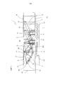
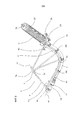
На фиг. 1 представлен схематический вид сбоку байпасной системы для воздушных линий электроснабжения в соответствии с вариантом осуществления данного изобретения в положении готовности.In FIG. 1 is a schematic side view of a bypass system for overhead power lines in accordance with an embodiment of the present invention in a standby position.
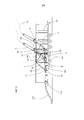
На фиг. 2 представлен схематический вид сбоку байпасной системы для воздушных линий электроснабжения согласно фиг. 1 в рабочем положении.In FIG. 2 is a schematic side view of a bypass system for overhead power lines according to FIG. 1 in working position.
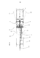
На фиг. 3 представлен вид сверху байпасной системы для воздушных линий электроснабжения согласно фиг. 2.In FIG. 3 is a plan view of a bypass system for overhead power lines of FIG. 2.
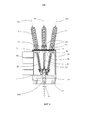
На фиг. 4 представлен вид сзади байпасной системы для воздушных линий электроснабжения согласно фиг. 2.In FIG. 4 is a rear view of a bypass system for overhead power lines according to FIG. 2.
На фиг. 5 представлена подробность несущей рамы и концевой муфты и подсоединенного к ним кабеля.In FIG. 5 shows a detail of a carrier frame and an end sleeve and a cable connected thereto.
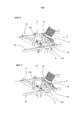
На фиг. 6 представлена подробность фазы перемещения, предназначенной для расположения концевой муфты и несущей рамы в рабочем положении.In FIG. 6 is a detail of the displacement phase for locating the end sleeve and the base frame in the operating position.
На фиг. 7 представлена подробность, иллюстрирующая концевую муфту и несущую раму, закрепленные в рабочем положении.In FIG. 7 is a detail illustrating an end sleeve and a supporting frame fixed in position.
ПОДРОБНОЕ ОПИСАНИЕDETAILED DESCRIPTION
Обращаясь к прилагаемым чертежам, отмечаем, что позиция 1 обозначает в целом байпасную систему для воздушных линий электроснабжения. Turning to the accompanying drawings, we note that
Байпасная система согласно изобретению приспособлена к использованию для обхода секции электрической линии, в которой, по меньшей мере, одна точка байпаса является точкой подвеса. Байпасную систему согласно изобретению предпочтительно используют на электрических линиях высокого и очень высокого напряжения, при этом под высоким напряжением понимается напряжение в диапазоне между 30 кВ и 150 кВ, а под очень высоким напряжением понимается напряжение выше 150 кВ.The bypass system according to the invention is adapted to be used to bypass a section of an electrical line in which at least one bypass point is a suspension point. The bypass system according to the invention is preferably used on electric lines of high and very high voltage, while high voltage means voltage between 30 kV and 150 kV, and very high voltage means voltage above 150 kV.
Байпасная система 1, показанная на чертежах, является примером и предназначена для использования на линиях напряжением 220 кВ и соответствующих подстанциях.The
Байпасная система содержит три несущие рамы 2, расположенные внутри корпуса Н, которые выполнены с возможностью перемещения между положением готовности (показанным на фиг. 1) и активным или рабочим положением (показанным на фиг. 2).The bypass system comprises three
Линия 9 электрического соединения, содержащая электрический кабель 4 и концевую муфту 3 наружной установки, поддерживается каждой несущей рамой 2.An
Как показано на фиг. 2, концевая муфта 3 наружной установки крепится своим нижним концом 3b к пластине 15 основания соответствующей несущей рамы 2, а верхний конец 3a муфты готов к электрическому соединению с воздушной линией электроснабжения посредством воздушного провода 3c, когда байпасная система находится в рабочем положении.As shown in FIG. 2, the
Электрический кабель 4 имеет первый конец 4a, электрически и механически соединяемый с концевой муфтой 3 наружной установки. Второй конец 4b электрического кабеля 4 готов к соединению с кабелем 100 (фиг. 2 и 3), например электрическим кабелем, предназначенным для электрического соединения со второй точкой байпаса (как будет подробнее пояснено ниже).The
Электрический кабель 4 подсоединен к соответствующей несущей раме 2 для перемещения как единого целого с концевой муфтой 3 наружной установки между положением готовности и рабочим положением байпасной системы 1.The
Байпасная система 1 дополнительно содержит исполнительные механизмы 5, действующие на соответствующие несущие рамы 2 для перемещения их между положением готовности и активным положением.The
Исполнительные механизмы 5 предпочтительно представляют собой линейные исполнительные механизмы, такие как гидравлические домкраты, винтовые домкраты или аналогичные средства. В альтернативном варианте можно использовать другие исполнительные механизмы, такие как исполнительные механизмы шестеренчатого типа или аналогичные механизмы.The
В качестве дополнительной альтернативы исполнительные механизмы можно исключить, в таком случае несущие рамы 2 перемещают в рабочее положение посредством внешнего устройства, такого как кран или аналогичное устройство.As an additional alternative, actuators can be omitted, in which case the supporting
Несущие рамы 2 содержат балку 6, имеющую по существу криволинейный профиль. В частности, балка 6 имеет два, по существу, прямолинейных концевых участка 6a, 6b - верхний и нижний соответственно, соединенные друг с другом с помощью криволинейного участка 6c. Как видно из фиг. 2, оба прямолинейных участка 6a, 6b имеют оси a1 и a2, которые располагаются под углом α друг к другу. Угол α находится в диапазоне между 15° и 80°, предпочтительно - между 30° и 60°, а в еще более предпочтительном варианте составляет примерно 45°, в зависимости от габаритов корпуса, чтобы несущая рама 2 и концевая муфта 3 наружной установки были полностью огорожены внутри корпуса H и чтобы концевая муфта 3 наружной установки и второй конец 4b кабеля находились в положении готовности к работе, когда несущая рама 2 поднята.Bearing frames 2 comprise a
В предпочтительном варианте осуществления изобретения балка 6 выполнена из стали имеет поперечное сечение, предназначенное для максимизации отношения между прочностью при изгибе и кручении и весом. Например, балка 6 может представлять собой трубу квадратного сечения, либо может иметь T- или U-образное поперечное сечение.In a preferred embodiment of the invention, the
Концевая муфта 3 наружной установки неподвижно прикреплена к верхнему концевому участку 6a балки 6, а второй конец 4b электрического кабеля 4 механически оперт на нижний концевой участок 6b балки 6.The end fitting 3 of the outdoor unit is fixedly attached to the
Электрический кабель 4 предпочтительно крепится к балке 6 в нескольких точках вдоль балки, а не только к верхнему и нижнему концевым участкам 6a, 6b балки 6, хомутами 6d или аналогичными средствами.The
Несущие рамы 2 содержат шарнир 7, способный поворачиваться вокруг оси X1 поворота. В данном описании и нижеследующей формуле изобретения под «шарниром» понимается любой конструктивный элемент, который создает ограничение, обеспечивающее поворот несущих рам 2 вокруг оси поворота.Bearing frames 2 comprise a
В варианте осуществления, показанном на прилагаемых чертежах, шарнир 7 представляет собой узел, включающий в себя втулку 7a, поворачивающуюся вокруг пальца 7b, поддерживаемого перекладинами 18 корпуса Н. Шарнир 7 расположен на некотором расстоянии от балки 6 за счет вогнутости балки.In the embodiment shown in the accompanying drawings, the
Шарнир 7 соединен с балкой 6 посредством множества распорок 8, имеющих первые концы 8a, соединенные с балкой 6, и вторые концы 8b, сходящиеся к оси X1 поворота и соединенные с втулкой 7a шарнира 7.The
Несущие рамы 2 выполнены с возможностью поворота вокруг осей X1, X2, X3 поворота соответственно. Прохождение несущих рам 2 из положения готовности в активное положение происходит посредством поворота рам вокруг упомянутых осей X1, X2, X3 поворота.Bearing frames 2 are rotatable around rotation axes X1, X2, X3, respectively. The passage of the supporting
Чтобы осуществить перемещение несущих рам 2, исполнительный механизм воздействует на несущие рамы 2.To carry out the movement of the supporting
Исполнительный механизм 5 настроен на приложение непосредственно действующей силы вдоль направления, по существу, по прямой, которая не пересекает ось X1, X2, X3 поворота (в зависимости от обстоятельств) несущих рам 2. В частности, исполнительный механизм 5 содержит два конца, соответственно 5a, 5b, прикрепленные шарнирно к несущей раме 2 и к платформе 10 корпуса Н. В частности, конец 5a исполнительного механизма 5, прикрепленный шарнирно к несущей раме 2, располагается около верхнего концевого участка 6a балки 6 несущей рамы 2 близко к концевой муфте 3 наружной установки.The
Таким образом, сила, прикладываемая исполнительным механизмом 5, вызывает поворот несущей рамы 2 вокруг шарнира 7.Thus, the force exerted by the
Корпус H байпасной системы 1 дополнительно содержит поддерживающие элементы 11, 12, на которые опираются несущие рамы 2, когда находятся в положении готовности. Поддерживающие элементы 11, 12 предпочтительно выполнены в виде раскосов или распорок, жестко скрепленных с платформой 10 корпуса H с тем, чтобы удерживать и жестко стопорить несущие рамы 2 и концевую муфту 3 наружной установки относительно платформы 10 во время транспортировки.The housing H of the
Поддерживающие элементы 11 предпочтительно воздействуют на верхний концевой участок 6a балки 6 несущей рамы 2.The supporting
Поддерживающие элементы 12 предпочтительно воздействуют на концевую муфту 3 наружной установки на ее верхнем конце 3a (фиг. 1).The supporting
Как видно из фиг. 2, несущие рамы 2 отсоединены от поддерживающих элементов 11, 12, когда исполнительные механизмы 5 приводятся в действие, поднимая несущие рамы в рабочее положение.As can be seen from FIG. 2, the supporting
Если это удобно, то поддерживающие элементы 11, 12 могут быть удалены во время работы байпасной системы (и снова размещены в нужном положении для транспортировки).If this is convenient, then the supporting
Когда несущая рама 2 поднята в рабочее положение, как показано на фиг. 6 и 7, на корпусе H размещены (например, вручную) поперечины 13, подсоединенные к нему винтами, крепежными деталями или аналогичными средствами.When the
Обычно, как показано на фиг. 6, несущую раму 2 поднимают выше заключительного рабочего положения, обеспечивая место для вставления и крепления поперечин 13, а потом опускают (фиг. 7), размещая опоры 13a, подсоединенные к пластине 15 основания, поверх поперечин 13.Typically, as shown in FIG. 6, the supporting
Когда несущая рама 2 находится в своем заключительном рабочем положении, опоры 13a можно жестко крепить к поперечинам 13, позволяя исполнительному механизму 5 освобождаться от нагрузки.When the
Корпус H обычно выполнен в виде жесткого каркаса, проходящего поверх платформы 10. Корпус H обычно имеет габариты грузового контейнера, так что возможна его перевозка посредством прицепа грузового автомобиля, или - в альтернативном варианте, как показано на фиг. 1-4, он сам может быть оснащен множеством колес 14, будучи выполненным в виде прицепа или полуприцепа.Housing H is usually in the form of a rigid frame extending over the
Корпус H обычно содержит платформу 10, боковые стенки 16 и верхнюю стенку 17. Такие стенки образуют удерживающий контейнер, огораживающий несущие рамы 2 и концевые муфты 3 наружной установки, когда несущие рамы 2 находятся в положении готовности.The housing H typically comprises a
Верхняя стенка 17 выполнена с возможностью, по меньшей мере, частичного перемещения для образования верхнего проема, так что концевые муфты 3 наружной установки могут выступать из корпуса Н, когда несущие рамы 2 находятся в активном положении, как показано на фиг. 2 и 4.The
В предпочтительном варианте боковые стенки 16 также выполнены с возможностью перемещения, обеспечивающего упрощенный доступ вовнутрь устройства.In a preferred embodiment, the
В предпочтительном варианте осуществления изобретения байпасная система 1 содержит три концевые муфты 3 наружной установки (по одной для каждой из трех фаз воздушной линии электроснабжения), с каждой из которых связаны соответствующие несущие рамы 2. Несущие рамы 2 и другие элементы байпасной системы 1, описанные выше и связанные с каждой концевой муфтой 3 наружной установки, по существу, идентичны друг другу за исключением следующего.In a preferred embodiment of the invention, the
Несущие рамы каждой концевой муфты 3 наружной установки опираются на перекладины 18 корпуса H и выполнены с возможностью поворота вокруг соответствующих осей X1, X2, X3 поворота (фиг. 4). Такие оси X1, X2, X3 поворота не параллельны друг другу.The bearing frames of each
В частности, центральная несущая рама 2C оперта так, что ее ось Х1 поворота проходит, по существу, горизонтально, а левая и правая несущие рамы 2L и 2R, расположенные на противоположных сторонах относительно центральной рамы, имеют оси X2, X3 поворота, наклоненные в противоположных направлениях. Оси X2, X3 поворота левой и правой несущих рам 2L и 2R предпочтительно наклонены зеркально по отношению к вертикальной плоскости P1 центральной несущей рамы 2C.In particular, the
Наклон осей X2, X3 поворота левой и правой несущих рам 2L и 2R таков, что соответствующие плоскости P2, P3 (фиг. 3 и 4), перпендикулярные им, расходятся кверху, предпочтительно - на угол β по отношению к вертикальной плоскости P1, предпочтительно находящийся в диапазоне между 2° и 45°, предпочтительнее - в диапазоне между 5° и 20°, еще предпочтительнее - составляющий примерно 10° (фактическое значение угла β зависит от размеров концевой муфты 3 наружной установки и корпуса H).The inclination of the rotation axes X2, X3 of the left and right bearing frames 2L and 2R is such that the corresponding planes P2, P3 (FIGS. 3 and 4), perpendicular to them, diverge upward, preferably by an angle β with respect to the vertical plane P1, preferably located between 2 ° and 45 °, more preferably between 5 ° and 20 °, even more preferably about 10 ° (the actual angle β depends on the dimensions of the
Центральная несущая рама 2C и соответствующая концевая муфта 3 наружной установки лежат в первой, по существу, вертикальной плоскости P1 (фиг. 3 и 4), а ось X1 поворота соответствующей несущей рамы 2 перпендикулярна первой плоскости P1.The
Левая и правая несущие рамы 2L и 2R и соответствующие концевые муфты 3 наружной установки лежат в соответствующих второй и третьей плоскостях P2, P3 (фиг. 3 и 4), перпендикулярных осям X2, X3 поворота несущих рам 2, и, соответственно, отклонены от первой плоскости P1 на угол β.The left and right bearing frames 2L and 2R and the corresponding end mounted
Таким образом, поворот несущих рам 2 - левой и правой несущих рам 2L и 2R - вызывает, в дополнение к подъему рам, постепенное взаимное разделение между соответствующими левой и правой концевыми муфтами наружной установки, а также между такими концевыми муфтами и центральной концевой муфтой, обеспечивая удержание концевых муфт 3 в близком положении, вследствие чего они имеют размер, подходящий для транспортировки по дорогам и разделение, когда они находятся в эксплуатации в течение периода, достаточного для того, чтобы избежать разрядов, при оставлении их соединенными с воздушной электрической сетью.Thus, the rotation of the bearing frames 2 — the left and right bearing frames 2L and 2R — causes, in addition to raising the frames, a gradual mutual separation between the corresponding left and right end couplings of the outdoor unit, as well as between such end couplings and the central end coupling, providing holding the
Второй конец 4b электрического кабеля 4 устроен с возможностью электрического и механического соединения с электрическим кабелем-удлинителем 100 (как показано на фиг. 2 и 3).The
Такой электрический кабель 100 имеет функцию сочленения байпасной системы 1, соединяемой с воздушной электрической линией одним концом обходимой секции, со вторым концом обходимой секции.Such an
В случае когда второй конец обходимой секции является точкой подвеса, кабель-удлинитель 100 будет обеспечивать соединение от первой байпасной системы 1 и второй, аналогичной байпасной системы 1, соединенной с такой точкой подвеса.In the case where the second end of the bypass section is the suspension point, the
В случае когда второй конец обходимой секции является точкой на грунте (или под грунтом), кабель-удлинитель 100 будет обеспечивать такой точке на грунте соединение с соответствующим сростком.In the case where the second end of the bypass section is a point on the ground (or under the ground), the
Чтобы обеспечить простое и правильное соединение электрического кабеля 4 с кабелем-удлинителем 100, байпасная система содержит сросток 19 кабеля для каждого электрического кабеля 4 (то есть для каждого из трех электрических кабелей 4).In order to ensure a simple and correct connection of the
Пример сростка кабеля, который можно использовать, описан в документе US 5316492; сростки кабелей этого типа есть в продаже под фирменным названием CLICK FIT® (например, модель CFJ-CFJX) и поставляются Заявителем.An example of a cable splice that can be used is described in US Pat. No. 5,316,492; cable splices of this type are commercially available under the brand name CLICK FIT ® (for example, model CFJ-CFJX) and are supplied by the Applicant.
Сростки 19 кабелей обычно соединяют с несущими рамами 2 посредством защелок 4d или аналогичных средств (фиг. 5).Cable splices 19 are usually connected to the carrier frames 2 by means of
Платформа 10 содержит один или несколько удерживающих элементов 10a для каждого кабеля-удлинителя 100, к которым кабель-удлинитель 100 прикреплен во время работы (фиг. 2).The
Кабель-удлинитель 100 можно с удобством транспортировать на место эксплуатации намотанным на барабан, откуда его можно разматывать во время операций прокладки байпасной системы, чтобы обеспечить достаточно длинное соединение, например - 50 метров, в ограниченном пространстве (которое определяется барабаном).
В предпочтительном варианте соответствующий кабель-удлинитель 100, намотанный на соответствующий барабан, предусматривается для каждой концевой муфты 3 наружной установки.In a preferred embodiment, a
При эксплуатации, три кабеля-удлинителя 100 предпочтительно прокладывают близко друг к другу и защелкивают, соединяя друг с другом в компоновке трилистником, формируя единую жилу.In use, the three
Один конец каждого из кабелей-удлинителей 100 снабжен соединительным разъемом, сопрягаемым с соответствующим сростком 19 кабеля, и выполнен с возможностью легкого вставления с тем, чтобы обеспечить быстрый монтаж.One end of each of the
В более предпочтительном варианте оба конца кабелей-удлинителей 100 снабжены соединительными разъемами, сопрягаемыми со сростками, относящимися к одному и тому же типу сростка 19, чтобы ускорить фазу соединения посредством обеих противоположных сторон кабелей-удлинителей 100.In a more preferred embodiment, both ends of the
При эксплуатации, байпасную систему 1 транспортируют с помощью прицепа грузового автомобиля или аналогичного средства в окрестность воздушной линии электроснабжения, где надлежит создать байпас.During operation, the
После этого корпус H закрепляют на нужном месте подходящими стойками 20 или аналогичными средствами, а несущие рамы 2 отсоединяют от поддерживающих элементов 11, 12, чтобы обеспечить перемещение несущих рам 2.After that, the housing H is fixed at the right place with
Во время этих операций, боковые и верхняя стенки 16, 17 корпуса H раскрыты, позволяя получить легкий доступ.During these operations, the side and
Потом приводят в действие исполнительные механизмы 5, чтобы повернуть несущие рамы 2, предпочтительно - по одной за раз.Then actuators 5 are actuated to rotate the supporting
Тогда концевые муфты 3 наружной установки выступают из верхнего проема корпуса H, достигая состояния, подходящего для эксплуатации.Then, the
На этой стадии поперечины 13 находятся в подходящих положениях для удержания несущих рам 2 и концевых муфт 3 наружной установки в поднятом положении.At this stage, the
После поворота несущих рам 2, второй конец 4b кабеля 4 и подсоединенный к нему сросток 19 достигают положения, подходящего для электрического соединения с кабелем-удлинителем 100.After the support frames 2 are rotated, the
Затем электрические кабели 4 и кабели-удлинители 100 механически и электрически соединяют и неподвижно прикрепляют к платформе 10.Then, the
Сразу же по окончании этих операций байпасная система готова к электрическому соединению с обходимой электрической линией.Immediately upon completion of these operations, the bypass system is ready for electrical connection with a bypassed electrical line.
Claims (15)
- корпус (Н);
- по меньшей мере, две несущие рамы (2), разнесенные в продольном направлении в упомянутом корпусе (Н), причем каждая несущая рама (2) связана с концевой муфтой (3) наружной установки,
при этом каждая несущая рама (2) выполнена с возможностью перемещения между резервным положением и рабочим положением концевой муфты (3) наружной установки;
- электрический кабель (4), электрически соединенный с каждой концевой муфтой (3) наружной установки.1. A bypass system for overhead power lines, comprising:
- case (N);
- at least two bearing frames (2), spaced in the longitudinal direction in said housing (H), with each bearing frame (2) connected to the end sleeve (3) of the outdoor unit,
wherein each carrier frame (2) is arranged to move between the standby position and the operating position of the end coupling (3) of the outdoor unit;
- an electric cable (4) electrically connected to each end sleeve (3) of the outdoor unit.
- обеспечение байпасной системы (1), включающей в себя, по меньшей мере, две несущие рамы (2), содержащиеся в корпусе и разнесенные в нем в продольном направлении, с соответствующей концевой муфтой (3) наружной установки, связанной с соответствующей несущей рамой (2), и электрический кабель (4), электрически соединенный с соответствующей концевой муфтой (3) наружной установки на его конце (4а);
- расположение упомянутой байпасной системы (1) в окрестности упомянутой секции электрической линии, при этом несущие рамы (2) находятся в резервном положении;
- перемещение упомянутой соответствующей несущей рамы (2) в рабочее положение концевой муфты (3) наружной установки;
- электрическое соединение соответствующей концевой муфты (3) наружной установки с упомянутым воздушным концом секции электрической линии.14. A method of operating a bypass of a section of an electrical line having an air end, including:
- providing a bypass system (1), comprising at least two supporting frames (2) contained in the housing and spaced in it in the longitudinal direction, with the corresponding end sleeve (3) of the outdoor unit associated with the corresponding supporting frame ( 2), and an electric cable (4) electrically connected to the corresponding end sleeve (3) of the outdoor unit at its end (4a);
- the location of the said bypass system (1) in the vicinity of the said section of the electric line, while the supporting frames (2) are in a standby position;
- the movement of the aforementioned corresponding supporting frame (2) in the working position of the end sleeve (3) of the outdoor installation;
- electrical connection of the corresponding end sleeve (3) of the outdoor installation with the aforementioned air end of the section of the electric line.
Applications Claiming Priority (1)
| Application Number | Priority Date | Filing Date | Title |
|---|---|---|---|
| PCT/EP2012/060660 WO2013182235A1 (en) | 2012-06-06 | 2012-06-06 | By-pass system for overhead power lines |
Publications (2)
| Publication Number | Publication Date |
|---|---|
| RU2014154404A RU2014154404A (en) | 2016-07-27 |
| RU2601739C2 true RU2601739C2 (en) | 2016-11-10 |
Family
ID=46420069
Family Applications (1)
| Application Number | Title | Priority Date | Filing Date |
|---|---|---|---|
| RU2014154404/07A RU2601739C2 (en) | 2012-06-06 | 2012-06-06 | Bypass system for overhead power lines |
Country Status (9)
| Country | Link |
|---|---|
| US (1) | US9997896B2 (en) |
| EP (1) | EP2859630B1 (en) |
| AU (1) | AU2012381803B2 (en) |
| BR (1) | BR112014030223B1 (en) |
| CA (1) | CA2874903C (en) |
| ES (1) | ES2646437T3 (en) |
| NO (1) | NO2859630T3 (en) |
| RU (1) | RU2601739C2 (en) |
| WO (1) | WO2013182235A1 (en) |
Families Citing this family (3)
| Publication number | Priority date | Publication date | Assignee | Title |
|---|---|---|---|---|
| CN110729095A (en) * | 2019-10-23 | 2020-01-24 | 国网浙江省电力有限公司经济技术研究院 | Vehicle-mounted movable transformer with position-adjustable wire outlet sleeve |
| DE102020112770A1 (en) | 2020-05-12 | 2021-11-18 | Südkabel GmbH | Arrangement for construction cables |
| CN112670899B (en) * | 2020-12-04 | 2022-07-22 | 国网河南省电力公司平顶山供电公司 | Power cable high altitude construction equipment |
Citations (6)
| Publication number | Priority date | Publication date | Assignee | Title |
|---|---|---|---|---|
| US2237812A (en) * | 1940-02-23 | 1941-04-08 | Gen Electric | Portable unit substation |
| SU1713010A1 (en) * | 1987-01-21 | 1992-02-15 | Московский институт инженеров сельскохозяйственного производства им.В.П.Горячкина | Method of power supply recovery under emergency conditions in insulated-neutral networks |
| FR2698737A1 (en) * | 1992-11-27 | 1994-06-03 | Scle Sa | Trailer-mounted HV by=pass circuit-breaker device for emergency use - has circuit-breaker, associated voltage and current transformers and isolator mounted on elevating and extending platform on trailer |
| RU2133079C1 (en) * | 1993-11-24 | 1999-07-10 | Ремоут Митеринг Системз Лтд. | Power supply network |
| DE10209658A1 (en) * | 2002-03-05 | 2003-10-30 | Abb Patent Gmbh | Elongated frame or baseplate for portable high-voltage switching gear, fits into rectangular protective housing with floors at ends |
| RU52276U1 (en) * | 2005-09-07 | 2006-03-10 | Общество с ограниченной ответственностью "Инициатива" | SECTION POINT FOR SWITCHING AND PROTECTION OF ELECTRIC TRANSMISSION AIRLINES |
Family Cites Families (10)
| Publication number | Priority date | Publication date | Assignee | Title |
|---|---|---|---|---|
| US2551841A (en) * | 1946-11-27 | 1951-05-08 | Westinghouse Electric Corp | Electrical apparatus |
| JPS5936091Y2 (en) * | 1978-11-24 | 1984-10-05 | 株式会社明電舎 | Mobile substation equipment |
| JPS5857216U (en) | 1981-10-13 | 1983-04-18 | 三菱電機株式会社 | mobile substation |
| US4427898A (en) * | 1981-12-22 | 1984-01-24 | Mitsubishi Denki Kabushiki Kaisha | Mobile power station apparatus |
| JPS58177915U (en) * | 1982-05-20 | 1983-11-28 | 三菱電機株式会社 | mobile electrical equipment |
| NL8901138A (en) | 1989-05-03 | 1990-12-03 | Nkf Kabel Bv | PLUG-IN CONNECTION FOR HIGH-VOLTAGE PLASTIC CABLES. |
| IT1277223B1 (en) | 1995-11-20 | 1997-11-05 | Abb Adda S P A | CONSTRUCTION GROUP TO BUILD A HIGH VOLTAGE ELECTRIC STATION |
| US6586697B1 (en) * | 2002-07-26 | 2003-07-01 | Pauwels Contracting Inc. | Transportable electrical switching assembly with high voltage circuit interrupter |
| US20090095522A1 (en) * | 2007-10-12 | 2009-04-16 | Barthold Lionel O | Robotic Bypass System and Method |
| ATE522817T1 (en) * | 2008-06-12 | 2011-09-15 | Abb Technology Ag | TEST ARRANGEMENT FOR AC VOLTAGE TESTING OF HIGH-VOLTAGE ELECTRICAL COMPONENTS |
-
2012
- 2012-06-06 EP EP12730821.1A patent/EP2859630B1/en active Active
- 2012-06-06 US US14/405,018 patent/US9997896B2/en active Active
- 2012-06-06 CA CA2874903A patent/CA2874903C/en active Active
- 2012-06-06 BR BR112014030223-5A patent/BR112014030223B1/en active IP Right Grant
- 2012-06-06 NO NO12730821A patent/NO2859630T3/no unknown
- 2012-06-06 ES ES12730821.1T patent/ES2646437T3/en active Active
- 2012-06-06 RU RU2014154404/07A patent/RU2601739C2/en active
- 2012-06-06 AU AU2012381803A patent/AU2012381803B2/en active Active
- 2012-06-06 WO PCT/EP2012/060660 patent/WO2013182235A1/en active Application Filing
Patent Citations (6)
| Publication number | Priority date | Publication date | Assignee | Title |
|---|---|---|---|---|
| US2237812A (en) * | 1940-02-23 | 1941-04-08 | Gen Electric | Portable unit substation |
| SU1713010A1 (en) * | 1987-01-21 | 1992-02-15 | Московский институт инженеров сельскохозяйственного производства им.В.П.Горячкина | Method of power supply recovery under emergency conditions in insulated-neutral networks |
| FR2698737A1 (en) * | 1992-11-27 | 1994-06-03 | Scle Sa | Trailer-mounted HV by=pass circuit-breaker device for emergency use - has circuit-breaker, associated voltage and current transformers and isolator mounted on elevating and extending platform on trailer |
| RU2133079C1 (en) * | 1993-11-24 | 1999-07-10 | Ремоут Митеринг Системз Лтд. | Power supply network |
| DE10209658A1 (en) * | 2002-03-05 | 2003-10-30 | Abb Patent Gmbh | Elongated frame or baseplate for portable high-voltage switching gear, fits into rectangular protective housing with floors at ends |
| RU52276U1 (en) * | 2005-09-07 | 2006-03-10 | Общество с ограниченной ответственностью "Инициатива" | SECTION POINT FOR SWITCHING AND PROTECTION OF ELECTRIC TRANSMISSION AIRLINES |
Also Published As
| Publication number | Publication date |
|---|---|
| AU2012381803B2 (en) | 2017-04-20 |
| CA2874903C (en) | 2019-04-30 |
| BR112014030223B1 (en) | 2021-04-06 |
| WO2013182235A1 (en) | 2013-12-12 |
| NO2859630T3 (en) | 2018-01-06 |
| ES2646437T3 (en) | 2017-12-13 |
| CA2874903A1 (en) | 2013-12-12 |
| US9997896B2 (en) | 2018-06-12 |
| EP2859630A1 (en) | 2015-04-15 |
| EP2859630B1 (en) | 2017-08-09 |
| RU2014154404A (en) | 2016-07-27 |
| AU2012381803A1 (en) | 2014-12-11 |
| BR112014030223A2 (en) | 2017-06-27 |
| US20150129274A1 (en) | 2015-05-14 |
Similar Documents
| Publication | Publication Date | Title |
|---|---|---|
| US6696925B1 (en) | Electrical revenue meter and instrument transformers mobile station | |
| AU2011201704B2 (en) | Live conductor stringing and splicing method and apparatus | |
| EP2939318B1 (en) | Container based by-pass module for electric power lines | |
| RU2601739C2 (en) | Bypass system for overhead power lines | |
| US20170338633A1 (en) | Quick connect and disconnect cable junction box | |
| US10748728B2 (en) | Boom mountable breaker and methods of using same | |
| US10770870B2 (en) | Containerized power flow control systems | |
| US20090195083A1 (en) | Live conductor stringing and splicing method and apparatus | |
| US8127436B2 (en) | Device for installing aerial electrical power lines | |
| Elizondo et al. | Ground based robots for energized transmission line work-technology description, field projects and technical-economical justification of their application | |
| Lopez-Roldan et al. | Technical considerations regarding the design and installations of mobile substations | |
| KR0138717B1 (en) | Cable establishment method | |
| KR200176364Y1 (en) | The construction work apparatus which is free of an electric power interruption | |
| Sharma et al. | Overview on Experience of EHV Cable Management in Sub-station–operation & Maintenance in Urban scenario |