RU2599592C2 - Device for embolic occlusion extraction - Google Patents
Device for embolic occlusion extraction Download PDFInfo
- Publication number
- RU2599592C2 RU2599592C2 RU2013136354/14A RU2013136354A RU2599592C2 RU 2599592 C2 RU2599592 C2 RU 2599592C2 RU 2013136354/14 A RU2013136354/14 A RU 2013136354/14A RU 2013136354 A RU2013136354 A RU 2013136354A RU 2599592 C2 RU2599592 C2 RU 2599592C2
- Authority
- RU
- Russia
- Prior art keywords
- structures
- width
- cells
- proximal
- distal
- Prior art date
Links
Images


Classifications
-
- A—HUMAN NECESSITIES
- A61—MEDICAL OR VETERINARY SCIENCE; HYGIENE
- A61F—FILTERS IMPLANTABLE INTO BLOOD VESSELS; PROSTHESES; DEVICES PROVIDING PATENCY TO, OR PREVENTING COLLAPSING OF, TUBULAR STRUCTURES OF THE BODY, e.g. STENTS; ORTHOPAEDIC, NURSING OR CONTRACEPTIVE DEVICES; FOMENTATION; TREATMENT OR PROTECTION OF EYES OR EARS; BANDAGES, DRESSINGS OR ABSORBENT PADS; FIRST-AID KITS
- A61F2/00—Filters implantable into blood vessels; Prostheses, i.e. artificial substitutes or replacements for parts of the body; Appliances for connecting them with the body; Devices providing patency to, or preventing collapsing of, tubular structures of the body, e.g. stents
- A61F2/82—Devices providing patency to, or preventing collapsing of, tubular structures of the body, e.g. stents
- A61F2/86—Stents in a form characterised by the wire-like elements; Stents in the form characterised by a net-like or mesh-like structure
- A61F2/90—Stents in a form characterised by the wire-like elements; Stents in the form characterised by a net-like or mesh-like structure characterised by a net-like or mesh-like structure
- A61F2/91—Stents in a form characterised by the wire-like elements; Stents in the form characterised by a net-like or mesh-like structure characterised by a net-like or mesh-like structure made from perforated sheet material or tubes, e.g. perforated by laser cuts or etched holes
- A61F2/915—Stents in a form characterised by the wire-like elements; Stents in the form characterised by a net-like or mesh-like structure characterised by a net-like or mesh-like structure made from perforated sheet material or tubes, e.g. perforated by laser cuts or etched holes with bands having a meander structure, adjacent bands being connected to each other
-
- A—HUMAN NECESSITIES
- A61—MEDICAL OR VETERINARY SCIENCE; HYGIENE
- A61B—DIAGNOSIS; SURGERY; IDENTIFICATION
- A61B17/00—Surgical instruments, devices or methods, e.g. tourniquets
- A61B17/22—Implements for squeezing-off ulcers or the like on the inside of inner organs of the body; Implements for scraping-out cavities of body organs, e.g. bones; Calculus removers; Calculus smashing apparatus; Apparatus for removing obstructions in blood vessels, not otherwise provided for
- A61B17/221—Gripping devices in the form of loops or baskets for gripping calculi or similar types of obstructions
-
- A—HUMAN NECESSITIES
- A61—MEDICAL OR VETERINARY SCIENCE; HYGIENE
- A61B—DIAGNOSIS; SURGERY; IDENTIFICATION
- A61B17/00—Surgical instruments, devices or methods, e.g. tourniquets
- A61B17/32—Surgical cutting instruments
- A61B17/3205—Excision instruments
- A61B17/3207—Atherectomy devices working by cutting or abrading; Similar devices specially adapted for non-vascular obstructions
- A61B17/320725—Atherectomy devices working by cutting or abrading; Similar devices specially adapted for non-vascular obstructions with radially expandable cutting or abrading elements
-
- A—HUMAN NECESSITIES
- A61—MEDICAL OR VETERINARY SCIENCE; HYGIENE
- A61B—DIAGNOSIS; SURGERY; IDENTIFICATION
- A61B17/00—Surgical instruments, devices or methods, e.g. tourniquets
- A61B17/32—Surgical cutting instruments
- A61B17/3205—Excision instruments
- A61B17/3207—Atherectomy devices working by cutting or abrading; Similar devices specially adapted for non-vascular obstructions
- A61B17/32075—Pullback cutting; combined forward and pullback cutting, e.g. with cutters at both sides of the plaque
-
- A—HUMAN NECESSITIES
- A61—MEDICAL OR VETERINARY SCIENCE; HYGIENE
- A61F—FILTERS IMPLANTABLE INTO BLOOD VESSELS; PROSTHESES; DEVICES PROVIDING PATENCY TO, OR PREVENTING COLLAPSING OF, TUBULAR STRUCTURES OF THE BODY, e.g. STENTS; ORTHOPAEDIC, NURSING OR CONTRACEPTIVE DEVICES; FOMENTATION; TREATMENT OR PROTECTION OF EYES OR EARS; BANDAGES, DRESSINGS OR ABSORBENT PADS; FIRST-AID KITS
- A61F2/00—Filters implantable into blood vessels; Prostheses, i.e. artificial substitutes or replacements for parts of the body; Appliances for connecting them with the body; Devices providing patency to, or preventing collapsing of, tubular structures of the body, e.g. stents
- A61F2/01—Filters implantable into blood vessels
-
- A—HUMAN NECESSITIES
- A61—MEDICAL OR VETERINARY SCIENCE; HYGIENE
- A61B—DIAGNOSIS; SURGERY; IDENTIFICATION
- A61B17/00—Surgical instruments, devices or methods, e.g. tourniquets
- A61B17/32—Surgical cutting instruments
- A61B17/3205—Excision instruments
- A61B17/3207—Atherectomy devices working by cutting or abrading; Similar devices specially adapted for non-vascular obstructions
-
- A—HUMAN NECESSITIES
- A61—MEDICAL OR VETERINARY SCIENCE; HYGIENE
- A61B—DIAGNOSIS; SURGERY; IDENTIFICATION
- A61B17/00—Surgical instruments, devices or methods, e.g. tourniquets
- A61B2017/00743—Type of operation; Specification of treatment sites
- A61B2017/00778—Operations on blood vessels
-
- A—HUMAN NECESSITIES
- A61—MEDICAL OR VETERINARY SCIENCE; HYGIENE
- A61B—DIAGNOSIS; SURGERY; IDENTIFICATION
- A61B17/00—Surgical instruments, devices or methods, e.g. tourniquets
- A61B17/22—Implements for squeezing-off ulcers or the like on the inside of inner organs of the body; Implements for scraping-out cavities of body organs, e.g. bones; Calculus removers; Calculus smashing apparatus; Apparatus for removing obstructions in blood vessels, not otherwise provided for
- A61B2017/22038—Implements for squeezing-off ulcers or the like on the inside of inner organs of the body; Implements for scraping-out cavities of body organs, e.g. bones; Calculus removers; Calculus smashing apparatus; Apparatus for removing obstructions in blood vessels, not otherwise provided for with a guide wire
- A61B2017/22045—Implements for squeezing-off ulcers or the like on the inside of inner organs of the body; Implements for scraping-out cavities of body organs, e.g. bones; Calculus removers; Calculus smashing apparatus; Apparatus for removing obstructions in blood vessels, not otherwise provided for with a guide wire fixed to the catheter; guiding tip
-
- A—HUMAN NECESSITIES
- A61—MEDICAL OR VETERINARY SCIENCE; HYGIENE
- A61B—DIAGNOSIS; SURGERY; IDENTIFICATION
- A61B17/00—Surgical instruments, devices or methods, e.g. tourniquets
- A61B17/22—Implements for squeezing-off ulcers or the like on the inside of inner organs of the body; Implements for scraping-out cavities of body organs, e.g. bones; Calculus removers; Calculus smashing apparatus; Apparatus for removing obstructions in blood vessels, not otherwise provided for
- A61B17/221—Gripping devices in the form of loops or baskets for gripping calculi or similar types of obstructions
- A61B2017/2215—Gripping devices in the form of loops or baskets for gripping calculi or similar types of obstructions having an open distal end
-
- A—HUMAN NECESSITIES
- A61—MEDICAL OR VETERINARY SCIENCE; HYGIENE
- A61F—FILTERS IMPLANTABLE INTO BLOOD VESSELS; PROSTHESES; DEVICES PROVIDING PATENCY TO, OR PREVENTING COLLAPSING OF, TUBULAR STRUCTURES OF THE BODY, e.g. STENTS; ORTHOPAEDIC, NURSING OR CONTRACEPTIVE DEVICES; FOMENTATION; TREATMENT OR PROTECTION OF EYES OR EARS; BANDAGES, DRESSINGS OR ABSORBENT PADS; FIRST-AID KITS
- A61F2/00—Filters implantable into blood vessels; Prostheses, i.e. artificial substitutes or replacements for parts of the body; Appliances for connecting them with the body; Devices providing patency to, or preventing collapsing of, tubular structures of the body, e.g. stents
- A61F2/01—Filters implantable into blood vessels
- A61F2002/016—Filters implantable into blood vessels made from wire-like elements
-
- A—HUMAN NECESSITIES
- A61—MEDICAL OR VETERINARY SCIENCE; HYGIENE
- A61F—FILTERS IMPLANTABLE INTO BLOOD VESSELS; PROSTHESES; DEVICES PROVIDING PATENCY TO, OR PREVENTING COLLAPSING OF, TUBULAR STRUCTURES OF THE BODY, e.g. STENTS; ORTHOPAEDIC, NURSING OR CONTRACEPTIVE DEVICES; FOMENTATION; TREATMENT OR PROTECTION OF EYES OR EARS; BANDAGES, DRESSINGS OR ABSORBENT PADS; FIRST-AID KITS
- A61F2/00—Filters implantable into blood vessels; Prostheses, i.e. artificial substitutes or replacements for parts of the body; Appliances for connecting them with the body; Devices providing patency to, or preventing collapsing of, tubular structures of the body, e.g. stents
- A61F2/01—Filters implantable into blood vessels
- A61F2002/018—Filters implantable into blood vessels made from tubes or sheets of material, e.g. by etching or laser-cutting
-
- A—HUMAN NECESSITIES
- A61—MEDICAL OR VETERINARY SCIENCE; HYGIENE
- A61F—FILTERS IMPLANTABLE INTO BLOOD VESSELS; PROSTHESES; DEVICES PROVIDING PATENCY TO, OR PREVENTING COLLAPSING OF, TUBULAR STRUCTURES OF THE BODY, e.g. STENTS; ORTHOPAEDIC, NURSING OR CONTRACEPTIVE DEVICES; FOMENTATION; TREATMENT OR PROTECTION OF EYES OR EARS; BANDAGES, DRESSINGS OR ABSORBENT PADS; FIRST-AID KITS
- A61F2/00—Filters implantable into blood vessels; Prostheses, i.e. artificial substitutes or replacements for parts of the body; Appliances for connecting them with the body; Devices providing patency to, or preventing collapsing of, tubular structures of the body, e.g. stents
- A61F2/82—Devices providing patency to, or preventing collapsing of, tubular structures of the body, e.g. stents
- A61F2002/825—Devices providing patency to, or preventing collapsing of, tubular structures of the body, e.g. stents having longitudinal struts
-
- A—HUMAN NECESSITIES
- A61—MEDICAL OR VETERINARY SCIENCE; HYGIENE
- A61F—FILTERS IMPLANTABLE INTO BLOOD VESSELS; PROSTHESES; DEVICES PROVIDING PATENCY TO, OR PREVENTING COLLAPSING OF, TUBULAR STRUCTURES OF THE BODY, e.g. STENTS; ORTHOPAEDIC, NURSING OR CONTRACEPTIVE DEVICES; FOMENTATION; TREATMENT OR PROTECTION OF EYES OR EARS; BANDAGES, DRESSINGS OR ABSORBENT PADS; FIRST-AID KITS
- A61F2230/00—Geometry of prostheses classified in groups A61F2/00 - A61F2/26 or A61F2/82 or A61F9/00 or A61F11/00 or subgroups thereof
- A61F2230/0002—Two-dimensional shapes, e.g. cross-sections
- A61F2230/0004—Rounded shapes, e.g. with rounded corners
- A61F2230/0006—Rounded shapes, e.g. with rounded corners circular
-
- A—HUMAN NECESSITIES
- A61—MEDICAL OR VETERINARY SCIENCE; HYGIENE
- A61F—FILTERS IMPLANTABLE INTO BLOOD VESSELS; PROSTHESES; DEVICES PROVIDING PATENCY TO, OR PREVENTING COLLAPSING OF, TUBULAR STRUCTURES OF THE BODY, e.g. STENTS; ORTHOPAEDIC, NURSING OR CONTRACEPTIVE DEVICES; FOMENTATION; TREATMENT OR PROTECTION OF EYES OR EARS; BANDAGES, DRESSINGS OR ABSORBENT PADS; FIRST-AID KITS
- A61F2230/00—Geometry of prostheses classified in groups A61F2/00 - A61F2/26 or A61F2/82 or A61F9/00 or A61F11/00 or subgroups thereof
- A61F2230/0063—Three-dimensional shapes
- A61F2230/0069—Three-dimensional shapes cylindrical
-
- A—HUMAN NECESSITIES
- A61—MEDICAL OR VETERINARY SCIENCE; HYGIENE
- A61F—FILTERS IMPLANTABLE INTO BLOOD VESSELS; PROSTHESES; DEVICES PROVIDING PATENCY TO, OR PREVENTING COLLAPSING OF, TUBULAR STRUCTURES OF THE BODY, e.g. STENTS; ORTHOPAEDIC, NURSING OR CONTRACEPTIVE DEVICES; FOMENTATION; TREATMENT OR PROTECTION OF EYES OR EARS; BANDAGES, DRESSINGS OR ABSORBENT PADS; FIRST-AID KITS
- A61F2230/00—Geometry of prostheses classified in groups A61F2/00 - A61F2/26 or A61F2/82 or A61F9/00 or A61F11/00 or subgroups thereof
- A61F2230/0063—Three-dimensional shapes
- A61F2230/0097—Harpoon-shaped
Landscapes
- Health & Medical Sciences (AREA)
- Life Sciences & Earth Sciences (AREA)
- Surgery (AREA)
- Biomedical Technology (AREA)
- Engineering & Computer Science (AREA)
- Public Health (AREA)
- Heart & Thoracic Surgery (AREA)
- Vascular Medicine (AREA)
- Veterinary Medicine (AREA)
- Animal Behavior & Ethology (AREA)
- General Health & Medical Sciences (AREA)
- Medical Informatics (AREA)
- Nuclear Medicine, Radiotherapy & Molecular Imaging (AREA)
- Molecular Biology (AREA)
- Orthopedic Medicine & Surgery (AREA)
- Oral & Maxillofacial Surgery (AREA)
- Cardiology (AREA)
- Transplantation (AREA)
- Physics & Mathematics (AREA)
- Optics & Photonics (AREA)
- Surgical Instruments (AREA)
- Media Introduction/Drainage Providing Device (AREA)
- Prostheses (AREA)
Abstract
Description
Ссылка на родственную заявкуLink to a related application
Согласно настоящей заявке испрашивается приоритет в соответствии с предварительной заявкой на выдачу патента США №13/303,890, поданной 23 ноября 2011 года, а также настоящая заявка является частичным продолжением указанной заявки, которая является частичным продолжением заявки на выдачу патента США №13/021,364, поданной 4 февраля 2011 года, которая является частичным продолжением заявки на выдачу патента США 12/832,857, поданной 8 июля 2010 года, которая является частичным продолжением заявки на выдачу патента США №12/643,942, поданной 21 декабря 2009 года, которая является частичным продолжением заявки на выдачу патента США №12/573,676, поданной 5 октября 2009 года, которая является частичным продолжением заявки на выдачу патента США №12/499,713, поданной 8 июля 2009 года.This application claims priority in accordance with provisional application for the grant of US patent No. 13/303,890, filed November 23, 2011, and this application is a partial continuation of this application, which is a partial continuation of the application for the grant of US patent No. 13/021,364, filed February 4, 2011, which is a partial continuation of the application for the grant of US
ОБЛАСТЬ ТЕХНИКИFIELD OF TECHNOLOGY
Настоящая заявка относится к устройствам и способам лечения сосудистой системы и других каналов в организме человека.This application relates to devices and methods for treating the vascular system and other channels in the human body.
УРОВЕНЬ ТЕХНИКИBACKGROUND
Саморасширяющиеся протезы, такие как стенты, покрытые стенты, сосудистые трансплантаты, устройства отклонения потока и т.п., были разработаны для лечения каналов в организме человека. Большое количество протезов было разработано для лечения блокад, возникающих в сосудистой системе, а также аневризмов, возникающих в мозгу. Существует необходимость в создании усовершенствованных способов и устройств для лечения каналов сосудистой системы и других каналов в организме человека, например, аневризм, стенозов, эмболических окклюзий и т.п.Self-expanding prostheses, such as stents, coated stents, vascular grafts, flow deflecting devices, etc., have been developed to treat canals in the human body. A large number of prostheses have been developed to treat blockages that occur in the vascular system, as well as aneurysms that occur in the brain. There is a need to create improved methods and devices for treating the channels of the vascular system and other channels in the human body, for example, aneurysms, stenoses, embolic occlusions, etc.
СУЩНОСТЬ ИЗОБРЕТЕНИЯSUMMARY OF THE INVENTION
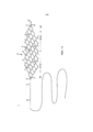
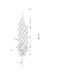
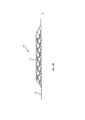
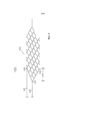
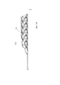
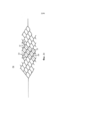
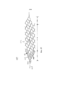
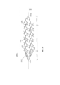
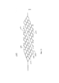
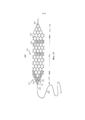
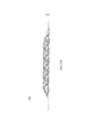
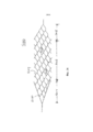
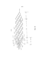
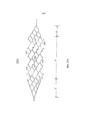
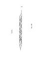
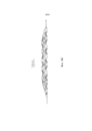
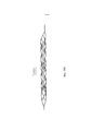
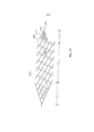
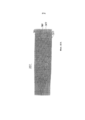
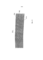
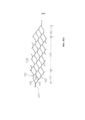
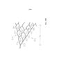
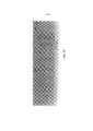
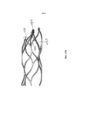
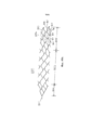
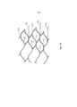
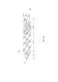
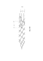
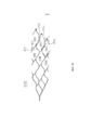
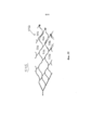
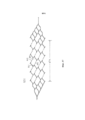
В соответствии с одним вариантом осуществления раскрыто устройство для лечения сосудов или других каналов в организме, которое содержит продолговатый саморасширяющийся элемент, выполненный с возможностью перемещения из первого положения для доставки во второе положение для размещения, причем в первом положении для доставки расширяющийся элемент находится в нерасширенном положении и характеризуется первым номинальным диаметром, а во втором положении расширяющийся элемент находится в радиально расширенном положении и характеризуется вторым номинальным диаметром, большим первого номинального диаметра для развертывания внутри сосуда или канала в организме пациента, причем расширяющийся элемент содержит несколько структур в виде ячеек, и расширяющийся элемент содержит проксимальную конечную часть с проксимальным концом, цилиндрическую часть в виде основного корпуса и дистальную конечную часть с дистальным концом, при этом структуры в виде ячеек в части в виде основного корпуса проходят по окружности вокруг продольной оси расширяющегося элемента, а структуры в виде ячеек в проксимальной и дистальной конечных частях проходят по части окружности вокруг продольной оси расширяющегося элемента, причем наиболее проксимальные структуры в виде ячеек в проксимальной конечной части содержат наиболее проксимальные линейные сегменты в виде стенок, которые, если смотреть на двухмерном изображении, образуют первый и второй по существу линейные сегменты в виде направляющих, каждый из которых проходит из положения в или рядом с наиболее проксимальным концом расширяющегося элемента к дистальному положению в или рядом с цилиндрической частью в виде основного корпуса. Согласно одному варианту осуществления саморасширяющийся элемент содержит продолговатое щелевое отверстие, проходящее вдоль, по меньшей мере, части длины саморасширяющегося элемента между проксимальным концом и дистальным концом.In accordance with one embodiment, a device for treating vessels or other channels in the body is disclosed that comprises an elongated self-expanding member configured to move from a first position for delivery to a second position for placement, wherein in the first position for delivery, the expanding member is in an unexpanded position and is characterized by a first nominal diameter, and in the second position, the expanding element is in a radially expanded position and characterizes a second nominal diameter larger than the first nominal diameter for deployment inside the vessel or channel in the patient’s body, the expanding element containing several structures in the form of cells, and the expanding element containing a proximal end part with a proximal end, a cylindrical part in the form of a main body and a distal end part with a distal end, while the structures in the form of cells in the part in the form of the main body extend around the circumference around the longitudinal axis of the expanding element, and the structures in de cells in the proximal and distal end parts extend along a part of a circle around the longitudinal axis of the expanding element, the most proximal structures in the form of cells in the proximal end part contain the most proximal linear segments in the form of walls, which, when viewed in a two-dimensional image, form the first and second essentially linear segments in the form of guides, each of which extends from a position at or near the most proximal end of the expanding element to a distal position in or next to the cylindrical part in the form of a main body. According to one embodiment, the self-expanding member comprises an elongated slotted hole extending along at least a portion of the length of the self-expanding member between the proximal end and the distal end.
Согласно другому варианту осуществления раскрывается набор, который содержит продолговатую гибкую проволоку, содержащую проксимальный конец и дистальный конец, причем продолговатый саморасширяющийся элемент присоединен к дистальному концу, и саморасширяющийся элемент выполнен с возможностью перемещения из первого положения для доставки во второе положение для размещения, причем в первом положении для доставки расширяющийся элемент находится в нерасширенном положении и характеризуется первым номинальным диаметром, а во втором положении расширяющийся элемент находится в радиально расширенном положении и характеризуется вторым номинальным диаметром, большим первого номинального диаметра для развертывания внутри сосуда или канала в организме пациента, саморасширяющийся элемент содержит несколько структур в виде ячеек, и саморасширяющийся элемент содержит проксимальную конечную часть с проксимальным концом, цилиндрическую часть в виде основного корпуса и дистальную конечную часть с дистальным концом, причем структуры в виде ячеек в части в виде основного корпуса проходят по окружности вокруг продольной оси расширяющегося элемента, а структуры в виде ячеек в проксимальной и дистальной конечных частях проходят по части окружности вокруг продольной оси расширяющегося элемента, причем наиболее проксимальные структуры в виде ячеек в проксимальной конечной части содержат наиболее проксимальные линейные сегменты в виде стенок, которые, если смотреть на двухмерном изображении, образуют первый и второй по существу линейные сегменты в виде направляющих, каждый из которых проходит из положения в или рядом с наиболее проксимальным концом расширяющегося элемента к дистальному положению в или рядом с цилиндрической частью в виде основного корпуса, причем продолговатая проволока с расширяемым элементом характеризуются первой длиной; а катетер для доставки характеризуется второй длиной и достаточной гибкостью для того, чтобы перемещаться через сосудистую систему или другие каналы в организме пациента, причем катетер для доставки содержит проксимальный конец, дистальный конец и внутреннюю полость, при этом внутренняя полость характеризуется диаметром, достаточным для размещения саморасширяющегося элемента в нерасширенном положении, а также для перемещения нерасширенного элемента от проксимального конца к дистальному концу катетера, причем вторая длина меньше первой длины для того, чтобы обеспечить дистальное перемещение саморасширяющегося элемента за пределы дистального конца катетера для обеспечения развертывания расширяющегося элемента в расширенное положение, при этом дистальный конец катетера и саморасширяющийся элемент выполнены с возможностью обеспечения проксимального втягивания саморасширяющегося элемента в полость катетера, когда саморасширяющийся элемент частично или полностью развернут снаружи дистального конца катетера. В соответствии с одним вариантом осуществления саморасширяющийся элемент содержит продолговатое щелевое отверстие, проходящее вдоль, по меньшей мере, части длины саморасширяющегося элемента между проксимальным концом и дистальным концом.According to another embodiment, a kit is disclosed which comprises an elongated flexible wire comprising a proximal end and a distal end, the elongated self-expanding member being attached to the distal end, and the self-expanding member being movable from a first position for delivery to a second position for placement, in the first In the delivery position, the expandable element is in the unexpanded position and is characterized by a first nominal diameter, and in the second floor In this case, the expanding element is in a radially expanded position and is characterized by a second nominal diameter larger than the first nominal diameter for deployment inside the vessel or channel in the patient’s body, the self-expanding element contains several structures in the form of cells, and the self-expanding element contains a proximal end part with a proximal end, a cylindrical part in the form of a main body and a distal end part with a distal end, and the structure in the form of cells in the part in the form of the main body whiskers run around a circle around the longitudinal axis of the expanding element, and structures in the form of cells in the proximal and distal end parts extend along a part of the circle around the longitudinal axis of the expanding element, the most proximal structures in the form of cells in the proximal end part contain the most proximal linear segments in the form of walls which, when viewed in a two-dimensional image, form the first and second essentially linear segments in the form of guides, each of which extends from a position to the silt and near the most proximal end of the expandable member to a distal position in or near the cylindrical part in the form of a main body, the elongated wire with the expandable member being characterized by a first length; and the delivery catheter is characterized by a second length and sufficient flexibility to travel through the vascular system or other channels in the patient’s body, the delivery catheter containing a proximal end, a distal end and an internal cavity, while the internal cavity is characterized by a diameter sufficient to accommodate a self-expanding the element in the unexpanded position, as well as to move the unexpanded element from the proximal end to the distal end of the catheter, the second length being less than length in order to allow distal movement of the self-expanding member beyond the distal end of the catheter to allow the expanding member to expand into an expanded position, the distal end of the catheter and the self-expanding member being configured to provide proximal retraction of the self-expanding member into the catheter cavity when the self-expanding member is partially or fully deployed outside the distal end of the catheter. In accordance with one embodiment, the self-expanding member comprises an elongated slotted hole extending along at least a portion of the length of the self-expanding member between the proximal end and the distal end.
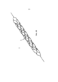
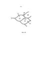
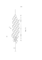
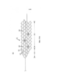
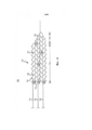
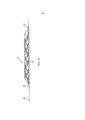
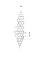
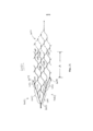
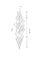
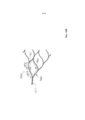
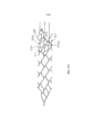
В соответствии с одним вариантом осуществления раскрыто устройство для лечения сосудов или других каналов в организме, которое содержит продолговатый саморасширяющийся элемент, выполненный с возможностью перемещения из первого положения для доставки во второе положение для размещения, причем в первом положении для доставки расширяющийся элемент находится в нерасширенном положении и характеризуется первым номинальным диаметром, а во втором положении расширяющийся элемент находится в радиально расширенном положении и характеризуется вторым номинальным диаметром, большим первого номинального диаметра для развертывания внутри сосудистой системы или канала в организме пациента, причем расширяющийся элемент содержит несколько в целом продолговатых волнообразных элементов, при этом смежные волнообразные элементы соединены друг с другом таким образом, чтобы образовать несколько диагонально расположенных структур в виде ячеек, и расширяющийся элемент содержит проксимальную конечную часть, цилиндрическую часть в виде основного корпуса и дистальную конечную часть, при этом структуры в виде ячеек в части в виде основного корпуса проходят по окружности вокруг продольной оси расширяющегося элемента, а структуры в виде ячеек в проксимальной и дистальной конечных частях проходят по части окружности вокруг продольной оси расширяющегося элемента, причем наиболее проксимальные структуры в виде ячеек в проксимальной конечной части содержат наиболее проксимальные линейные сегменты в виде стенок, которые, если смотреть на двухмерном изображении, образуют первый и второй по существу линейные сегменты в виде направляющих, каждый из которых проходит из положения в или рядом с наиболее проксимальным концом расширяющегося элемента к положению в или рядом с цилиндрической частью в виде основного корпуса. В соответствии с одним вариантом осуществления к наиболее проксимальному концу расширяющегося элемента присоединена проксимально проходящая продолговатая гибкая проволока, характеризующаяся длиной и гибкостью, достаточными для осуществления доступа к сосудистой системе или другому каналу в организме пациента и для перемещения по ним.In accordance with one embodiment, a device for treating vessels or other channels in the body is disclosed that comprises an elongated self-expanding member configured to move from a first position for delivery to a second position for placement, wherein in the first position for delivery, the expanding member is in an unexpanded position and is characterized by a first nominal diameter, and in the second position, the expanding element is in a radially expanded position and characterizes a second nominal diameter, larger than the first nominal diameter for deployment inside the vascular system or channel in the patient’s body, the expanding element containing several generally oblong wave-like elements, while adjacent wave-like elements are connected to each other so as to form several diagonally located structures in in the form of cells, and the expanding element contains a proximal end part, a cylindrical part in the form of a main body and a distal end part, while the structures in the form of cells in the part in the form of the main body extend around the circumference around the longitudinal axis of the expanding element, and the structures in the form of cells in the proximal and distal end parts extend along the circumference around the longitudinal axis of the expanding element, the most proximal structures in the form of cells in the proximal end part contains the most proximal linear segments in the form of walls, which, when viewed in a two-dimensional image, form the first and second essentially linear segments in e guides, each of which extends from a position at or near the most proximal end of the expandable member to a position at or near to the cylindrical portion of the main body. In accordance with one embodiment, a proximal extending elongated flexible wire is attached to the most proximal end of the expandable member, characterized by a length and flexibility sufficient to allow access to the vascular system or other channel in the patient's body and to move through them.
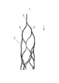
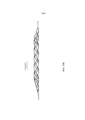
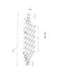
В соответствии с другим вариантом осуществления раскрыто устройство для лечения сосудов, которое содержит продолговатый саморасширяющийся элемент, выполненный с возможностью перемещения из первого положения для доставки во второе положение для размещения, причем в первом положении для доставки расширяющийся элемент находится в нерасширенном положении и характеризуется первым номинальным диаметром, а во втором положении расширяющийся элемент находится в радиально расширенном положении и характеризуется вторым номинальным диаметром, большим первого номинального диаметра для развертывания внутри сосудистой системы пациента, причем расширяющийся элемент содержит несколько в целом продолговатых волнообразных элементов, при этом смежные волнообразные элементы соединены друг с другом таким образом, чтобы образовать несколько структур в виде ячеек, которые расположены для инициирования кручения расширяющегося элемента при переходе расширяющегося элемента из нерасширенного положения в расширенное положение, и расширяющийся элемент содержит проксимальную конечную часть, цилиндрическую часть в виде основного корпуса и дистальную конечную часть, при этом структуры в виде ячеек в части в виде основного корпуса проходят по окружности вокруг продольной оси расширяющегося элемента, а структуры в виде ячеек в проксимальной и дистальной конечных частях проходят по части окружности вокруг продольной оси расширяющегося элемента, причем наиболее проксимальные структуры в виде ячеек в проксимальной конечной части содержат наиболее проксимальные линейные сегменты в виде стенок, которые образуют первый и второй по существу линейные сегменты в виде направляющих, каждый из которых проходит из положения в или рядом с наиболее проксимальным концом расширяющегося элемента к положению в или рядом с цилиндрической частью в виде основного корпуса. В соответствии с одним вариантом осуществления к наиболее проксимальному концу расширяющегося элемента присоединена проксимально проходящая продолговатая гибкая проволока, характеризующаяся длиной и гибкостью, достаточными для осуществления доступа к сосудистой системе или другому каналу в организме пациента и для перемещения по ним.In accordance with another embodiment, a vascular treatment device is disclosed that comprises an elongated self-expanding member configured to move from a first delivery position to a second position for placement, wherein in the first delivery position, the expandable member is in an unexpanded position and is characterized by a first nominal diameter and in the second position the expanding element is in a radially expanded position and is characterized by a second nominal diameter ohm, larger than the first nominal diameter for deployment inside the patient’s vascular system, the expanding element contains several generally oblong wave-like elements, while adjacent wave-like elements are connected to each other so as to form several structures in the form of cells that are arranged to initiate torsion of the expanding element upon transition of the expanding element from the unexpanded position to the expanded position, and the expanding element contains a proximal end the main part, the cylindrical part in the form of the main body and the distal end part, while the structures in the form of cells in the part in the form of the main body extend around the circumference around the longitudinal axis of the expanding element, and the structures in the form of cells in the proximal and distal end parts extend along the part of the circle around the longitudinal axis of the expanding element, and the most proximal cell-shaped structures in the proximal end part contain the most proximal linear segments in the form of walls that form the first and the second essentially linear segments in the form of guides, each of which extends from a position at or near the most proximal end of the expanding element to a position at or near the cylindrical part in the form of a main body. In accordance with one embodiment, a proximal extending elongated flexible wire is attached to the most proximal end of the expandable member, characterized by a length and flexibility sufficient to allow access to the vascular system or other channel in the patient's body and to move through them.
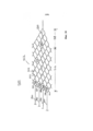
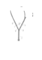
В соответствии с другим вариантом осуществления раскрыто устройство для лечения сосудов или других каналов в организме, которое содержит продолговатый саморасширяющийся элемент, выполненный с возможностью перемещения из первого положения для доставки во второе положение для размещения, причем в первом положении для доставки расширяющийся элемент находится в нерасширенном положении и характеризуется первым номинальным диаметром, а во втором положении расширяющийся элемент находится в радиально расширенном положении и характеризуется вторым номинальным диаметром, большим первого номинального диаметра для развертывания внутри канала в организме или сосудистой системы пациента, причем расширяющийся элемент содержит несколько в целом продольных волнообразных элементов, при этом смежные волнообразные элементы соединены друг с другом таким образом, чтобы образовывать несколько диагонально расположенных структур в виде ячеек, и расширяющийся элемент содержит цилиндрическую часть и дистальную конечную часть, при этом структуры в виде ячеек в цилиндрической части проходят по окружности вокруг продольной оси расширяющегося элемента, а структуры в виде ячеек в дистальной конечной части проходят по части окружности вокруг продольной оси расширяющегося элемента, причем наиболее проксимальные структуры в виде ячеек в части в виде основного корпуса содержат наиболее проксимальные конечные точки. Одна или несколько наиболее проксимальных конечных точек расширяющегося элемента содержат проксимально проходящую продолговатую гибкую проволоку, характеризующуюся длиной и гибкостью, достаточными для осуществления доступа к сосудистой системе или другому каналу в организме пациента и для перемещения по ним.In accordance with another embodiment, a device for treating vessels or other channels in the body is disclosed that comprises an elongated self-expanding member configured to move from a first position for delivery to a second position for placement, wherein in the first position for delivery, the expandable member is in an unexpanded position and is characterized by a first nominal diameter, and in the second position, the expanding element is in a radially expanded position and is characterized by a second nominal diameter larger than the first nominal diameter for deployment inside the channel in the body or vascular system of the patient, the expanding element containing several generally longitudinal wave-like elements, while adjacent wave-like elements are connected to each other so as to form several diagonally located structures in in the form of cells, and the expanding element contains a cylindrical part and a distal end part, while structures in the form of cells in the cylindrical part rohodyat circumferentially around the longitudinal axis of the expandable member, as well as the structure of cells in the distal end portion are on the circumference around the longitudinal axis of the expandable member, the most proximal cell structure in the form of a portion of the main body contain the most proximal end points. One or more of the most proximal end points of the expanding element contains a proximal extending elongated flexible wire, characterized by a length and flexibility sufficient to allow access to the vascular system or other channel in the patient's body and to move through them.
В соответствии с другим вариантом осуществления раскрывается набор, который содержит продолговатую гибкую проволоку, содержащую проксимальный конец и дистальный конец, причем продолговатый саморасширяющийся элемент прикреплен к дистальному концу, и саморасширяющийся элемент выполнен с возможностью перемещения из первого положения для доставки во второе положение для размещения, причем в первом положении для доставки расширяющийся элемент находится в нерасширенном положении и характеризуется первым номинальным диаметром, а во втором положении расширяющийся элемент находится в радиально расширенном положении и характеризуется вторым номинальным диаметром, большим первого номинального диаметра для развертывания внутри сосуда или канала в организме пациента, причем расширяющийся элемент содержит несколько в целом продольных волнообразных элементов, при этом смежные волнообразные элементы соединены друг с другом таким образом, чтобы образовывать несколько диагонально расположенных структур в виде ячеек, и расширяющийся элемент содержит проксимальную конечную часть, цилиндрическую часть в виде основного корпуса и дистальную конечную часть, причем структуры в виде ячеек в части в виде основного корпуса проходят по окружности вокруг продольной оси расширяющегося элемента, а структуры в виде ячеек в проксимальной и дистальной конечных частях проходят по части окружности вокруг продольной оси расширяющегося элемента, причем наиболее проксимальные структуры в виде ячеек в проксимальной конечной части содержат наиболее проксимальные линейные сегменты в виде стенок, которые, если смотреть на двухмерном изображении, образуют первый и второй по существу линейные сегменты в виде направляющих, каждый из которых проходит из положения в или рядом с наиболее проксимальным концом расширяющегося элемента к положению в или рядом с цилиндрической частью в виде основного корпуса, причем продолговатая проволока с расширяемым элементом характеризуются первой длиной, а катетер для доставки характеризуется второй длиной и достаточной гибкостью для того, чтобы перемещаться через сосудистую систему или другие каналы в организме пациента, причем катетер для доставки содержит проксимальный конец, дистальный конец и внутренний диаметр, при этом внутренний диаметр является достаточным для размещения расширяющегося элемента в нерасширенном положении, а также для перемещения нерасширенного элемента от проксимального конца к дистальному концу катетера, причем вторая длина меньше первой длины для того, чтобы обеспечить дистальное перемещение расширяющегося элемента за пределы дистального конца катетера для обеспечения развертывания расширяющегося элемента в расширенное положение, при этом дистальный конец катетера и расширяющийся элемент сконфигурированы для обеспечения проксимального втягивания расширяющегося элемента в катетер, когда расширяющийся элемент частично или полностью развернут снаружи дистального конца катетера.According to another embodiment, a kit is disclosed that comprises an elongated flexible wire comprising a proximal end and a distal end, the elongated self-expanding member being attached to the distal end, and the self-expanding member being movable from a first position for delivery to a second position for placement, wherein in the first position for delivery, the expandable element is in the unexpanded position and is characterized by the first nominal diameter, and in the second In the expanded position, the expanding element is in a radially expanded position and is characterized by a second nominal diameter larger than the first nominal diameter for deployment inside the vessel or channel in the patient’s body, the expanding element containing several generally longitudinal wave-like elements, while adjacent wave-shaped elements are connected to each other by in such a way as to form several diagonally arranged structures in the form of cells, and the expanding element contains a proximal finite part, the cylindrical part in the form of the main body and the distal end part, and the structures in the form of cells in the part in the form of the main body run in a circle around the longitudinal axis of the expanding element, and the structures in the form of cells in the proximal and distal end parts pass in the part of the circle around the longitudinal axis of the expanding element, the most proximal structures in the form of cells in the proximal end part contain the most proximal linear segments in the form of walls, which, when viewed at two the first and second substantially linear segments in the form of guides, each of which extends from a position at or near the most proximal end of the expanding element to a position at or near the cylindrical part in the form of a main body, the elongated wire with an expandable element being characterized the first length, and the delivery catheter is characterized by a second length and sufficient flexibility to move through the vascular system or other channels in the patient’s body, wherein the delivery catheter comprises a proximal end, a distal end and an inner diameter, wherein the inner diameter is sufficient to accommodate the expandable member in the unexpanded position, as well as to move the unexpanded member from the proximal end to the distal end of the catheter, the second length being less than the first length to allow distal movement of the expandable member beyond the distal end of the catheter to allow deployment of the expandable member in the expanded dix, wherein the distal end of the catheter and expandable element are configured to provide a proximal retraction of the catheter into the expandable member when the expandable member is partially or fully deployed outside the distal end of the catheter.
В соответствии с другим вариантом осуществления раскрыт способ удаления эмболической окклюзии из сосуда пациента, который предусматривает: (a) перемещение катетера для доставки, содержащего внутреннюю полость с проксимальным и дистальным концом, к месту расположения эмболической окклюзии в интракраниальной сосудистой системе пациента таким образом, чтобы дистальный конец внутренней полости располагался дистально по отношению к эмболической окклюзии, причем внутренняя полость характеризуется первой длиной; (b) введение устройства для извлечения эмболической окклюзии, содержащего продолговатую гибкую проволоку, содержащую проксимальный конец и дистальный конец, причем продолговатый саморасширяемым элемент прикреплен к дистальному концу, в проксимальный конец внутренней полости катетера, и перемещение саморасширяющегося элемента к дистальному концу полости, саморасширяющийся элемент выполнен с возможностью перемещения из первого положения для доставки во второе положение для размещения, причем в первом положении для доставки расширяющийся элемент находится в нерасширенном положении и характеризуется первым номинальным диаметром, а во втором положении расширяющийся элемент находится в радиально расширенном положении и характеризуется вторым номинальным диаметром, большим первого номинального диаметра для развертывания внутри эмболической окклюзии пациента, причем расширяющийся элемент содержит несколько в целом продольных волнообразных элементов, при этом смежные волнообразные элементы соединены друг с другом таким образом, чтобы образовывать несколько структур в виде ячеек, и расширяющийся элемент содержит проксимальную конечную часть, цилиндрическую часть в виде основного корпуса и дистальную конечную часть, причем структуры в виде ячеек в части в виде основного корпуса проходят по окружности вокруг продольной оси расширяющегося элемента, а структуры в виде ячеек в проксимальной и дистальной конечных частях проходят по части окружности вокруг продольной оси расширяющегося элемента, причем внешние структуры в виде ячеек в проксимальной конечной части содержат проксимальные линейные сегменты в виде стенок, которые, если смотреть на двухмерном изображении, образуют первый и второй по существу линейные сегменты в виде направляющих, каждый из которых проходит из положения в или рядом с проксимальным концом расширяющегося элемента к положению в или рядом с цилиндрической частью в виде основного корпуса, причем продолговатая проволока и расширяющийся элемент в сочетании характеризуются второй длиной, большей первой длины; (c) проксимальное извлечение катетера для доставки, достаточное для развертывания саморасширяющегося устройства таким образом, чтобы одна или несколько структур в виде ячеек захватывали, по меньшей мере, часть эмболической окклюзии; и (d) проксимальное извлечение катетера для доставки и саморасширяющегося устройства из пациента. Согласно альтернативной реализации саморасширяющийся элемент частично или полностью отводят во внутреннюю полость катетера для доставки перед проксимальным извлечением катетера для доставки и саморасширяющегося устройства из организма пациента.According to another embodiment, a method is disclosed for removing embolic occlusion from a patient’s vessel, which comprises: (a) moving a delivery catheter containing an internal cavity with a proximal and distal end to a location of embolic occlusion in the patient's intracranial vascular system so that the distal the end of the inner cavity was located distally with respect to embolic occlusion, the inner cavity being characterized by a first length; (b) introducing an embolic occlusion retrieval device comprising an elongated flexible wire comprising a proximal end and a distal end, the elongated self-expanding member being attached to the distal end, to the proximal end of the catheter inner cavity, and moving the self-expanding member to the distal end of the cavity, the self-expanding member with the possibility of moving from the first position for delivery to the second position for placement, and in the first position for delivery I expand The element is in the unexpanded position and is characterized by the first nominal diameter, and in the second position, the expanding element is in the radially expanded position and is characterized by the second nominal diameter, larger than the first nominal diameter for deployment inside the patient's embolic occlusion, the expanding element containing several generally longitudinal wave-like elements while adjacent wavy elements are connected to each other so as to form several a round in the form of cells, and the expanding element contains a proximal end part, a cylindrical part in the form of a main body and a distal end part, moreover, the structures in the form of cells in the part in the form of the main body extend in a circle around the longitudinal axis of the expanding element, and the structures in the form of cells in the proximal and distal end parts extend along a part of the circle around the longitudinal axis of the expanding element, and the external structures in the form of cells in the proximal end part contain proximal linear copies in the form of walls, which, when viewed in a two-dimensional image, form the first and second essentially linear segments in the form of guides, each of which extends from a position at or near the proximal end of the expanding element to a position in or near the cylindrical part in the form of a main cases, and the elongated wire and the expanding element in combination are characterized by a second length greater than the first length; (c) proximal retrieval of the delivery catheter sufficient to deploy a self-expanding device so that one or more cell structures capture at least a portion of the embolic occlusion; and (d) proximal removal of the delivery catheter and self-expanding device from the patient. According to an alternative implementation, the self-expanding element is partially or completely withdrawn into the internal cavity of the catheter for delivery before the proximal removal of the catheter for delivery and the self-expanding device from the patient.
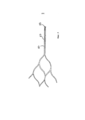
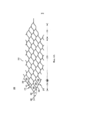
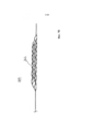
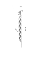
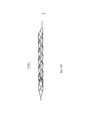
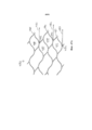
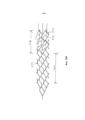
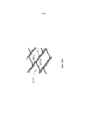
В соответствии с другим вариантом осуществления раскрыто устройство, которое содержит продолговатый саморасширяющийся элемент, выполненный с возможностью перемещения из первого положения для доставки во второе положение для размещения, причем в первом положении для доставки расширяющийся элемент находится в нерасширенном положении и характеризуется первым номинальным диаметром, а во втором положении расширяющийся элемент находится в радиально расширенном положении и характеризуется вторым номинальным диаметром, большим первого номинального диаметра для развертывания внутри сосуда или канала в организме пациента, причем расширяющийся элемент содержит несколько структур в виде ячеек, и расширяющийся элемент содержит проксимальную конечную часть с проксимальным концом и цилиндрическую часть в виде основного корпуса, при этом структуры в виде ячеек в части в виде основного корпуса содержат первое множество пересекающихся распорок и проходят по окружности вокруг продольной оси расширяющегося элемента, а структуры в виде ячеек в проксимальной конечной части содержат второе множество пересекающихся распорок и проходят по части окружности вокруг продольной оси расширяющегося элемента, причем, по меньшей мере, некоторые из первого множества пересекающихся распорок характеризуются отношением толщины к ширине, составляющим более единицы.In accordance with another embodiment, a device is disclosed that comprises an elongated self-expanding member configured to move from a first position for delivery to a second position for placement, wherein in the first position for delivery, the expanding member is in an unexpanded position and is characterized by a first nominal diameter, and in in the second position, the expandable element is in a radially expanded position and is characterized by a second nominal diameter larger than the first of nominal diameter for deployment inside the vessel or channel in the patient’s body, the expanding element containing several structures in the form of cells, and the expanding element containing the proximal end part with a proximal end and a cylindrical part in the form of the main body, while the structure in the form of cells in the part in the form the main body contain the first set of intersecting spacers and run in a circle around the longitudinal axis of the expanding element, and the structure in the form of cells in the proximal end of the soda neigh second plurality of intersecting struts and extend part circumferentially around the longitudinal axis of the expandable member, wherein at least some of the first plurality of intersecting struts characterized by a ratio of thickness to width ratio of more than unity.
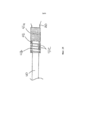
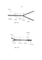
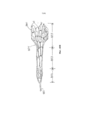
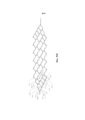
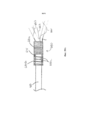
В соответствии с еще одним вариантом осуществления раскрыто устройство, которое содержит проволоку для доставки и продолговатый саморасширяющийся элемент, выполненный с возможностью перемещения из первого положения для доставки во второе положение для размещения, причем в первом положении для доставки расширяющийся элемент находится в нерасширенном положении и характеризуется первым номинальным диаметром, а во втором положении расширяющийся элемент находится в радиально расширенном положении и характеризуется вторым номинальным диаметром, большим первого номинального диаметра для развертывания внутри сосуда или канала в организме пациента, причем расширяющийся элемент содержит несколько структур в виде ячеек, и расширяющийся элемент содержит проксимальную конечную часть с проксимальным концом и цилиндрическую часть в виде основного корпуса, причем проксимальный конец содержит выполненный как одно целое с ним и проходящий из него сегмент проволоки с катушкой, расположенной поверх сегмента проволоки, причем катушка содержит первый плотно намотанный сегмент и второй неплотно намотанный сегмент, который содержит по меньшей мере один зазор, при этом структуры в виде ячеек в части в виде основного корпуса проходят по окружности вокруг продольной оси расширяющегося элемента, а структуры в виде ячеек в проксимальной конечной части проходят по части окружности вокруг продольной оси расширяющегося элемента, причем проксимальный конец сегмента проволоки прикреплен к дистальному концу проволоки для доставки при помощи связующего агента внутри второго неплотно намотанного сегмента катушки.In accordance with yet another embodiment, a device is disclosed that comprises a delivery wire and an elongated self-expanding member configured to move from a first delivery position to a second position for placement, wherein in the first delivery position, the expandable member is in an unexpanded position and is characterized by a first nominal diameter, and in the second position, the expanding element is in a radially expanded position and is characterized by a second nominal diameter larger than the first nominal diameter for deployment inside the vessel or channel in the patient’s body, the expanding element containing several structures in the form of cells, and the expanding element containing a proximal end part with a proximal end and a cylindrical part in the form of a main body, the proximal end comprising integral with it and passing from it a segment of wire with a coil located on top of the segment of the wire, and the coil contains the first tightly wound segment the second loosely wound segment, which contains at least one gap, while the structures in the form of cells in the part in the form of the main body extend around the circumference around the longitudinal axis of the expanding element, and the structures in the form of cells in the proximal end part extend along the part of the circle around the longitudinal axis an expanding element, the proximal end of the wire segment being attached to the distal end of the wire for delivery with a bonding agent inside the second loosely wound segment of the coil.
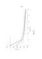
В соответствии с еще одним вариантом осуществления раскрыто устройство, которое содержит продолговатый саморасширяющийся элемент, выполненный с возможностью перемещения из первого положения для доставки во второе положение для размещения, причем в первом положении для доставки расширяющийся элемент находится в нерасширенном положении и характеризуется первым номинальным диаметром, а во втором положении расширяющийся элемент находится в радиально расширенном положении и характеризуется вторым номинальным диаметром, большим первого номинального диаметра для развертывания внутри сосуда или канала в организме пациента, причем расширяющийся элемент содержит несколько структур в виде ячеек, и расширяющийся элемент содержит проксимальную конечную часть с проксимальным концом и цилиндрическую часть в виде основного корпуса, причем структуры в виде ячеек в цилиндрической части в виде основного корпуса проходят по окружности вокруг продольной оси расширяющегося элемента, а структуры в виде ячеек в проксимальной конечной части проходят по части окружности вокруг продольной оси расширяющегося элемента, причем структуры в виде ячеек характеризуются геометрическими характеристиками и характеристиками материала, которые в результате обеспечивают общее снижение радиального усилия вдоль длины расширяющегося элемента, составляющее от приблизительно -1,5 Н до приблизительно -3,5 Н на один миллиметр расширения, при первоначальном расширении диаметра на приблизительно 0,50 мм от номинального диаметра, и которые обеспечивают общее снижение радиального усилия вдоль длины расширяющегося элемента, составляющее от приблизительно -0,10 Н до приблизительно -0,50 Н на один миллиметр расширения, при последующем расширении диаметра. Согласно одной реализации продолговатый саморасширяющийся элемент характеризуется предполагаемым максимальным вторым номинальным диаметром, причем радиальное усилие, прикладываемое продолговатым саморасширяемым элементом, составляет больше нуля при расширении до максимального второго номинального диаметра.In accordance with another embodiment, a device is disclosed that comprises an elongated self-expanding member configured to move from a first position for delivery to a second position for placement, wherein in the first position for delivery, the expanding member is in an unexpanded position and is characterized by a first nominal diameter, and in the second position, the expandable element is in a radially expanded position and is characterized by a second nominal diameter larger than the first about the nominal diameter for deployment inside the vessel or channel in the patient’s body, the expanding element containing several structures in the form of cells, and the expanding element containing the proximal end part with a proximal end and a cylindrical part in the form of the main body, and the structure in the form of cells in the cylindrical part in in the form of the main body, they circle around the longitudinal axis of the expanding element, and the structures in the form of cells in the proximal end part extend along the part of the circle around the the axis of the expanding element, wherein the cell-shaped structures are characterized by geometric and material characteristics, which as a result provide a general reduction in radial force along the length of the expanding element, from about -1.5 N to about -3.5 N per millimeter of expansion, upon initial expansion of the diameter by approximately 0.50 mm from the nominal diameter, and which provide an overall reduction in radial force along the length of the expanding member from about 0.10 N to about 0.50 N per millimeter of expansion upon subsequent expansion diameter. According to one implementation, an elongated self-expanding element is characterized by an estimated maximum second nominal diameter, the radial force exerted by the elongated self-expanding element being greater than zero when expanding to a maximum second nominal diameter.
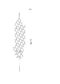
В соответствии с еще одним вариантом осуществления раскрыто устройство, которое содержит продолговатый саморасширяющийся элемент, выполненный с возможностью перемещения из первого положения для доставки во второе положение для размещения, причем в первом положении для доставки расширяющийся элемент находится в нерасширенном положении и характеризуется первым номинальным диаметром, а во втором положении расширяющийся элемент находится в радиально расширенном положении и характеризуется вторым номинальным диаметром, большим первого номинального диаметра для развертывания внутри сосудистой системы или канала в организме пациента, причем расширяющийся элемент содержит несколько в целом продолговатых волнообразных элементов, при этом смежные волнообразные элементы соединены друг с другом таким образом, чтобы образовать несколько диагонально расположенных структур в виде ячеек, и расширяющийся элемент содержит проксимальную конечную часть, цилиндрическую часть в виде основного корпуса и дистальную конечную часть, причем структуры в виде ячеек в части в виде основного корпуса проходят по окружности вокруг продольной оси расширяющегося элемента, структуры в виде ячеек в проксимальной и дистальных конечных частях проходят по части окружности вокруг продольной оси расширяющегося элемента, а структуры в виде ячеек в проксимальной конечной части проходят по части окружности вокруг продольной оси расширяющегося элемента, причем структуры в виде ячеек характеризуются геометрическими характеристиками и характеристиками материала, которые в результате обеспечивают общее снижение радиального усилия вдоль длины расширяющегося элемента, составляющее от приблизительно -1,5 Н до приблизительно -3,5 Н на один миллиметр расширения, при первоначальном расширении диаметра на приблизительно 0,50 мм от первого номинального диаметра, и которые обеспечивают общее снижение радиального усилия вдоль длины расширяющегося элемента, составляющее от приблизительно -0,10 Н до приблизительно -0,50 Н на один миллиметр расширения, при последующем расширении диаметра. Согласно одной реализации продолговатый саморасширяющийся элемент характеризуется предполагаемым максимальным вторым номинальным диаметром, причем радиальное усилие, прикладываемое продолговатым саморасширяемым элементом, составляет больше нуля при расширении до максимального второго номинального диаметра.In accordance with another embodiment, a device is disclosed that comprises an elongated self-expanding member configured to move from a first position for delivery to a second position for placement, wherein in the first position for delivery, the expanding member is in an unexpanded position and is characterized by a first nominal diameter, and in the second position, the expandable element is in a radially expanded position and is characterized by a second nominal diameter larger than the first about the nominal diameter for deployment inside the vascular system or channel in the patient’s body, the expanding element containing several generally oblong wave-like elements, while adjacent wave-like elements are connected to each other so as to form several diagonally arranged structures in the form of cells, and an expanding element contains a proximal end part, a cylindrical part in the form of a main body and a distal end part, moreover, the structures in the form of cells in the part in the form of main the oval body extend around the circumference around the longitudinal axis of the expanding element, the structures in the form of cells in the proximal and distal end parts extend along the circumference around the longitudinal axis of the expanding element, and the structures in the form of cells in the proximal end part extend along the circumference around the longitudinal axis of the expanding element, moreover, the structures in the form of cells are characterized by geometric characteristics and characteristics of the material, which as a result provide an overall decrease in the radial axis along the length of the expanding element, comprising from about −1.5 N to about −3.5 N per millimeter of expansion, with an initial expansion of the diameter of approximately 0.50 mm from the first nominal diameter, and which provide an overall reduction in radial force along the length expanding element, comprising from about -0.10 N to about -0.50 N per millimeter of expansion, with subsequent expansion of the diameter. According to one implementation, an elongated self-expanding element is characterized by an estimated maximum second nominal diameter, the radial force exerted by the elongated self-expanding element being greater than zero when expanding to a maximum second nominal diameter.
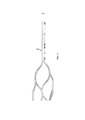
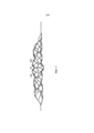
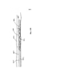
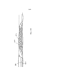
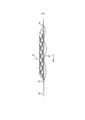
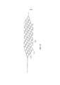
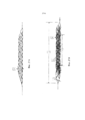
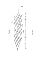
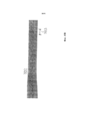
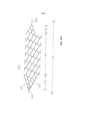
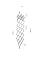
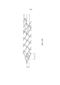
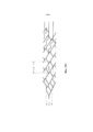
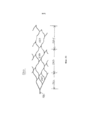
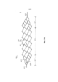
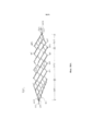
В соответствии с другим вариантом осуществления раскрыто устройство для извлечения тромбов, которое содержит продолговатый саморасширяющийся элемент, выполненный с возможностью перемещения из первого положения для доставки во второе положение для размещения, причем в первом положении для доставки расширяющийся элемент находится в нерасширенном положении и характеризуется первым номинальным диаметром, а во втором положении расширяющийся элемент находится в радиально расширенном положении и характеризуется вторым номинальным диаметром, большим первого номинального диаметра для развертывания внутри эмболической окклюзии пациента, причем расширяющийся элемент содержит несколько в целом продолговатых волнообразных элементов, при этом смежные волнообразные элементы соединены друг с другом таким образом, чтобы образовать несколько диагонально расположенных структур в виде ячеек, и расширяющийся элемент содержит проксимальную конечную часть и цилиндрическую часть в виде основного корпуса, при этом структуры в виде ячеек в части в виде основного корпуса проходят по окружности вокруг продольной оси расширяющегося элемента, а структуры в виде ячеек в проксимальной конечной части проходят по части окружности вокруг продольной оси расширяющегося элемента для образования первой и второй периферийных направляющих, содержащих проксимальный и дистальный конечные сегменты, причем структуры в виде ячеек в проксимальной конечной части содержат первый набор структур в виде ячеек, расположенный для образования первой периферийной направляющей, второй набор структур в виде ячеек, расположенный для образования второй периферийной направляющей, и третий набор структур в виде ячеек, расположенный между первым и вторым набором структур в виде ячеек, при этом первый и второй наборы структур в виде ячеек содержат общую наиболее проксимальную структуру в виде ячейки, причем структуры в виде ячеек в части в виде основного корпус содержат четвертый набор структур в виде ячеек, и наиболее проксимальная структура в виде ячейки и первый набор структур в виде ячеек содержат наиболее внешние проходящие по окружности распорные элементы, которые определяют первую периферийную направляющую, а наиболее проксимальная структура в виде ячейки и второй набор структур в виде ячеек содержат наиболее внешние проходящие по окружности распорные элементы, которые определяют вторую периферийную направляющую, причем, по меньшей мере, некоторые из наиболее внешних проходящих по окружности распорных элементов характеризуются различными размерами ширины и расположены таким образом, чтобы размер первой и второй периферийных направляющих варьировался между первым размером ширины в проксимальном конечном сегменте и вторым размером ширины в дистальном конечном сегменте, причем второй размер ширины меньше первого размера ширины. Согласно одной реализации первая и вторая периферийные направляющие не содержат волнистости и процентное изменение между первым размером ширины и вторым размером ширины составляет от приблизительно 20,0% до приблизительно 50,0%.In accordance with another embodiment, a thrombus extraction device is disclosed that comprises an elongated self-expanding member configured to move from a first position for delivery to a second position for placement, wherein in the first position for delivery, the expanding member is in an unexpanded position and is characterized by a first nominal diameter , and in the second position, the expanding element is in a radially expanded position and is characterized by a second nominal diameter a meter larger than the first nominal diameter for deployment inside the patient's embolic occlusion, the expanding element containing several generally oblong wave-like elements, while adjacent wave-like elements are connected to each other so as to form several diagonally arranged structures in the form of cells, and the expanding element contains the proximal end part and the cylindrical part in the form of the main body, while the structures in the form of cells in the part in the form of the main body pass circumferentially around the longitudinal axis of the expanding element, and structures in the form of cells in the proximal end part extend along a part of the circumference around the longitudinal axis of the expanding element to form the first and second peripheral guides containing the proximal and distal end segments, and the structures in the form of cells in the proximal end part contain the first set of structures in the form of cells located for the formation of the first peripheral guide, the second set of structures in the form of cells located for the image a second peripheral guide and a third set of structures in the form of cells located between the first and second set of structures in the form of cells, the first and second sets of structures in the form of cells contain the common most proximal structure in the form of a cell, and the structures in the form of cells in part in the form of the main body, they contain the fourth set of structures in the form of cells, and the most proximal structure in the form of a cell and the first set of structures in the form of cells contain the most external spacing elements passing around the circumference, which determine they divide the first peripheral guide, and the most proximal structure in the form of a cell and the second set of structures in the form of cells contain the outermost circumferential spacer elements that define the second peripheral guide, and at least some of the outermost circumferential spacer elements are characterized different widths and are arranged so that the size of the first and second peripheral guides varies between the first width size in the proximal the final segment and the second width dimension in the distal end segment, the second width dimension being smaller than the first width dimension. According to one implementation, the first and second peripheral guides do not contain waviness and the percentage change between the first width size and the second width size is from about 20.0% to about 50.0%.
В соответствии с другими вариантами осуществления раскрыты устройства для извлечения тромбов, которые содержат продолговатый саморасширяющийся элемент, выполненный с возможностью перемещения из первого положения для доставки во второе положение для размещения, причем в первом положении для доставки расширяющийся элемент находится в нерасширенном положении и характеризуется первым номинальным диаметром, а во втором положении расширяющийся элемент находится в радиально расширенном положении и характеризуется вторым номинальным диаметром, большим первого номинального диаметра для развертывания внутри эмболической окклюзии пациента, причем расширяющийся элемент содержит несколько в целом продолговатых волнообразных элементов, при этом смежные волнообразные элементы соединены друг с другом таким образом, чтобы образовать несколько диагонально расположенных структур в виде ячеек, и расширяющийся элемент содержит проксимальную конечную часть и цилиндрическую часть в виде основного корпуса, при этом структуры в виде ячеек в части в виде основного корпуса проходят по окружности вокруг продольной оси расширяющегося элемента, а структуры в виде ячеек в проксимальной конечной части проходят по части окружности вокруг продольной оси расширяющегося элемента для образования первой и второй периферийных направляющих, содержащих проксимальный и дистальный конечные сегменты, причем структуры в виде ячеек в проксимальной конечной части содержат первый набор структур в виде ячеек, расположенный для образования первой периферийной направляющей, второй набор структур в виде ячеек, расположенный для образования второй периферийной направляющей, и третий набор структур в виде ячеек, расположенный между первым и вторым набором структур в виде ячеек, при этом первый и второй наборы структур в виде ячеек содержат общую наиболее проксимальную структуру в виде ячейки, причем структуры в виде ячеек в части в виде основного корпус содержат четвертый набор структур в виде ячеек, и наиболее проксимальная структура в виде ячейки и первый набор структур в виде ячеек содержат наиболее внешние проходящие по окружности распорные элементы, которые определяют первую периферийную направляющую, а наиболее проксимальная структура в виде ячейки и второй набор структур в виде ячеек содержат наиболее внешние проходящие по окружности распорные элементы, которые определяют вторую периферийную направляющую, причем, по меньшей мере, некоторые из наиболее внешних проходящих по окружности распорных элементов характеризуются различными размерами ширины и расположены таким образом, чтобы размер первой и второй периферийных направляющих варьировался между первым размером ширины в проксимальном конечном сегменте и вторым размером ширины в дистальном конечном сегменте, причем второй размер ширины меньше первого размера ширины, причем процентное изменение между первым размером ширины и вторым размером ширины составляет от приблизительно 20,0% до приблизительно 50,0%, при этом третий набор структур в виде ячеек содержит распорки, характеризующиеся третьим размером ширины, который меньше второго размера ширины, и четвертый набор структур в виде ячеек содержит распорки, характеризующиеся четвертым размером ширины, который меньше второго размера ширины, причем выраженная в процентах разница между вторым размером ширины и третьим размером ширины составляет от приблизительно 10,0% до приблизительно 25,0%, а выраженная в процентах разница между вторым размером ширины и четвертым размером ширины составляет от приблизительно 10% до приблизительно 25,0%.In accordance with other embodiments, thrombus extraction devices are disclosed that comprise an elongated self-expanding member configured to move from a first position for delivery to a second position for placement, wherein in the first position for delivery, the expanding member is in an unexpanded position and is characterized by a first nominal diameter and in the second position the expanding element is in a radially expanded position and is characterized by a second nominal an ameter larger than the first nominal diameter for deployment inside the patient's embolic occlusion, the expanding element containing several generally oblong wave-like elements, while adjacent wave-like elements are connected to each other so as to form several diagonally arranged structures in the form of cells, and the expanding element contains the proximal end part and the cylindrical part in the form of the main body, while the structure in the form of cells in the part in the form of the main body passage m in a circle around the longitudinal axis of the expanding element, and structures in the form of cells in the proximal end part extend along a part of the circle around the longitudinal axis of the expanding element to form the first and second peripheral guides containing the proximal and distal end segments, and the structures in the form of cells in the proximal end the parts contain a first set of structures in the form of cells located to form the first peripheral guide, a second set of structures in the form of cells located for the second peripheral guide, and the third set of structures in the form of cells located between the first and second set of structures in the form of cells, the first and second sets of structures in the form of cells contain the common most proximal structure in the form of a cell, and the structure in the form of cells in part in the form of the main body, they contain the fourth set of structures in the form of cells, and the most proximal structure in the form of a cell and the first set of structures in the form of cells contain the most external spacing elements passing around the circumference, which determine eat the first peripheral guide, and the most proximal structure in the form of a cell and the second set of structures in the form of cells contain the outermost circumferential spacer elements that define the second peripheral guide, and at least some of the most outer circumferential spacer elements are characterized different widths and are arranged so that the size of the first and second peripheral guides varies between the first width size in the proximal m of the final segment and the second width dimension in the distal end segment, the second width dimension being smaller than the first width dimension, wherein the percentage change between the first width dimension and the second width dimension is from about 20.0% to about 50.0%, the third set cell structures contains spacers characterized by a third width dimension that is smaller than the second width dimension, and a fourth set of cell structures contains spacers characterized by a fourth width dimension that is smaller than w the width, and the percentage difference between the second width and the third width is from about 10.0% to about 25.0%, and the percentage difference between the second and the fourth width is from about 10% to approximately 25.0%.
В соответствии с другим вариантом осуществления раскрыто устройство для извлечения тромбов, которое содержит продолговатый саморасширяющийся элемент, выполненный с возможностью перемещения из первого положения для доставки во второе положение для размещения, причем в первом положении для доставки расширяющийся элемент находится в нерасширенном положении и характеризуется первым номинальным диаметром, а во втором положении расширяющийся элемент находится в радиально расширенном положении и характеризуется вторым номинальным диаметром, большим первого номинального диаметра для развертывания внутри эмболической окклюзии пациента, причем расширяющийся элемент содержит несколько в целом продолговатых волнообразных элементов, при этом смежные волнообразные элементы соединены друг с другом таким образом, чтобы образовать несколько диагонально расположенных структур в виде ячеек, и расширяющийся элемент содержит проксимальную конечную часть и цилиндрическую часть в виде основного корпуса, при этом структуры в виде ячеек в части в виде основного корпуса проходят по окружности вокруг продольной оси расширяющегося элемента, а структуры в виде ячеек в проксимальной конечной части проходят по части окружности вокруг продольной оси расширяющегося элемента для образования первой и второй периферийных направляющих, содержащих проксимальный и дистальный конечные сегменты, причем структуры в виде ячеек в проксимальной конечной части содержат первый набор структур в виде ячеек, расположенный для образования первой периферийной направляющей, второй набор структур в виде ячеек, расположенный для образования второй периферийной направляющей, и третий набор структур в виде ячеек, расположенный между первым и вторым набором структур в виде ячеек, при этом первый и второй наборы структур в виде ячеек содержат общую наиболее проксимальную структуру в виде ячейки, причем структуры в виде ячеек в части в виде основного корпус содержат четвертый набор структур в виде ячеек, и наиболее проксимальная структура в виде ячейки и первый набор структур в виде ячеек содержат наиболее внешние проходящие по окружности распорные элементы, которые определяют первую периферийную направляющую, а наиболее проксимальная структура в виде ячейки и второй набор структур в виде ячеек содержат наиболее внешние проходящие по окружности распорные элементы, которые определяют вторую периферийную направляющую, причем, по меньшей мере, некоторые из наиболее внешних проходящих по окружности распорных элементов характеризуются различными размерами ширины и расположены таким образом, чтобы размер первой и второй периферийных направляющих варьировался между первым размером ширины в проксимальном конечном сегменте и вторым размером ширины в дистальном конечном сегменте, причем второй размер ширины меньше первого размера ширины, причем процентное изменение между первым размером ширины и вторым размером ширины составляет от приблизительно 20,0% до приблизительно 50,0%, при этом третий набор структур в виде ячеек содержит распорки, характеризующиеся третьим размером ширины, который меньше второго размера ширины, и четвертый набор структур в виде ячеек содержит распорки, характеризующиеся четвертым размером ширины, который по существу равен второму размеру ширины, причем выраженная в процентах разница между вторым размером ширины и третьим размером ширины составляет от приблизительно 10,0% до приблизительно 25,0%.In accordance with another embodiment, a thrombus extraction device is disclosed that comprises an elongated self-expanding member configured to move from a first position for delivery to a second position for placement, wherein in the first position for delivery, the expanding member is in an unexpanded position and is characterized by a first nominal diameter , and in the second position, the expanding element is in a radially expanded position and is characterized by a second nominal diameter a meter larger than the first nominal diameter for deployment inside the patient's embolic occlusion, the expanding element containing several generally oblong wave-like elements, while adjacent wave-like elements are connected to each other so as to form several diagonally arranged structures in the form of cells, and the expanding element contains the proximal end part and the cylindrical part in the form of the main body, while the structures in the form of cells in the part in the form of the main body pass circumferentially around the longitudinal axis of the expanding element, and structures in the form of cells in the proximal end part extend along a part of the circumference around the longitudinal axis of the expanding element to form the first and second peripheral guides containing the proximal and distal end segments, and the structures in the form of cells in the proximal end part contain the first set of structures in the form of cells located for the formation of the first peripheral guide, the second set of structures in the form of cells located for the image a second peripheral guide and a third set of structures in the form of cells located between the first and second set of structures in the form of cells, the first and second sets of structures in the form of cells contain the common most proximal structure in the form of a cell, and the structures in the form of cells in part in the form of the main body, they contain the fourth set of structures in the form of cells, and the most proximal structure in the form of a cell and the first set of structures in the form of cells contain the most external spacing elements passing around the circumference, which determine they divide the first peripheral guide, and the most proximal structure in the form of a cell and the second set of structures in the form of cells contain the outermost circumferential spacer elements that define the second peripheral guide, and at least some of the outermost circumferential spacer elements are characterized different widths and are arranged so that the size of the first and second peripheral guides varies between the first width size in the proximal the final segment and the second width dimension in the distal end segment, the second width dimension being smaller than the first width dimension, wherein the percentage change between the first width dimension and the second width dimension is from about 20.0% to about 50.0%, with a third set of structures in the form of cells contains spacers characterized by a third width dimension that is smaller than the second width dimension, and a fourth set of cell structures contains spacers characterized by a fourth width dimension which is essentially equal to the second width dimension, wherein the percentage difference between the second width dimension and the third width dimension is from about 10.0% to about 25.0%.
В соответствии с другим вариантом осуществления раскрыто устройство для извлечения тромбов, которое содержит продолговатый саморасширяющийся элемент, выполненный с возможностью перемещения из первого положения для доставки во второе положение для размещения, причем в первом положении для доставки расширяющийся элемент находится в нерасширенном положении и характеризуется первым номинальным диаметром, а во втором положении расширяющийся элемент находится в радиально расширенном положении и характеризуется вторым номинальным диаметром, большим первого номинального диаметра для развертывания внутри эмболической окклюзии пациента, причем расширяющийся элемент содержит несколько в целом продолговатых волнообразных элементов, при этом смежные волнообразные элементы соединены друг с другом таким образом, чтобы образовать несколько диагонально расположенных структур в виде ячеек, и расширяющийся элемент содержит проксимальную конечную часть и цилиндрическую часть в виде основного корпуса, при этом структуры в виде ячеек в части в виде основного корпуса проходят по окружности вокруг продольной оси расширяющегося элемента, а структуры в виде ячеек в проксимальной конечной части проходят по части окружности вокруг продольной оси расширяющегося элемента для образования первой и второй периферийных направляющих, содержащих проксимальный и дистальный конечные сегменты, причем структуры в виде ячеек в проксимальной конечной части содержат первый набор структур в виде ячеек, расположенный для образования первой периферийной направляющей, второй набор структур в виде ячеек, расположенный для образования второй периферийной направляющей, и третий набор структур в виде ячеек, расположенный между первым и вторым набором структур в виде ячеек, при этом первый и второй наборы структур в виде ячеек содержат общую наиболее проксимальную структуру в виде ячейки, причем структуры в виде ячеек в части в виде основного корпус содержат четвертый и пятый наборы структур в виде ячеек, и наиболее проксимальная структура в виде ячейки и первый набор структур в виде ячеек содержат наиболее внешние проходящие по окружности распорные элементы, которые определяют первую периферийную направляющую, а наиболее проксимальная структура в виде ячейки и второй набор структур в виде ячеек содержат наиболее внешние проходящие по окружности распорные элементы, которые определяют вторую периферийную направляющую, причем, по меньшей мере, некоторые из наиболее внешних проходящих по окружности распорных элементов характеризуются различными размерами ширины и расположены таким образом, чтобы размер первой и второй периферийных направляющих варьировался между первым размером ширины в проксимальном конечном сегменте и вторым размером ширины в дистальном конечном сегменте, причем второй размер ширины меньше первого размера ширины, причем размер структур в виде ячеек в третьем и пятом наборе структур в виде ячеек являются по существу одинаковым, а размер структур в виде ячеек в четвертом наборе структур в виде ячеек больше размера структур в виде ячеек в третьем наборе структур в виде ячеек, причем структуры в виде ячеек в третьем, четвертом и пятом наборах структур в виде ячеек содержат третьи, четвертые и пятые распорки, соответственно, при этом, по меньшей мере, некоторые из четвертых и пятых распорок, или их сегменты, характеризуются размером ширины, который больше размера ширины третьих распорок.In accordance with another embodiment, a thrombus extraction device is disclosed that comprises an elongated self-expanding member configured to move from a first position for delivery to a second position for placement, wherein in the first position for delivery, the expanding member is in an unexpanded position and is characterized by a first nominal diameter , and in the second position, the expanding element is in a radially expanded position and is characterized by a second nominal diameter a meter larger than the first nominal diameter for deployment inside the patient's embolic occlusion, the expanding element containing several generally oblong wave-like elements, while adjacent wave-like elements are connected to each other so as to form several diagonally arranged structures in the form of cells, and the expanding element contains the proximal end part and the cylindrical part in the form of the main body, while the structures in the form of cells in the part in the form of the main body pass circumferentially around the longitudinal axis of the expanding element, and structures in the form of cells in the proximal end part extend along a part of the circumference around the longitudinal axis of the expanding element to form the first and second peripheral guides containing the proximal and distal end segments, and the structures in the form of cells in the proximal end part contain the first set of structures in the form of cells located for the formation of the first peripheral guide, the second set of structures in the form of cells located for the image a second peripheral guide and a third set of structures in the form of cells located between the first and second set of structures in the form of cells, the first and second sets of structures in the form of cells contain the common most proximal structure in the form of a cell, and the structures in the form of cells in part in the form of the main body, they contain the fourth and fifth sets of structures in the form of cells, and the most proximal structure in the form of a cell and the first set of structures in the form of cells contain the most external spacer elements passing around They define the first peripheral guide, and the most proximal structure in the form of a cell and the second set of structures in the form of cells contain the outermost circumferential spacer elements that define the second peripheral guide, and at least some of the outermost circumferential spacer elements are characterized by different widths and are arranged so that the size of the first and second peripheral guides varies between the first width size in the proxy the final size segment and the second width dimension in the distal end segment, the second width dimension being smaller than the first width dimension, the cell size structures in the third and fifth set of cell structures being essentially the same, and the size of the cell structures in the fourth set structures in the form of cells are larger than the size of structures in the form of cells in the third set of structures in the form of cells, and structures in the form of cells in the third, fourth and fifth sets of structures in the form of cells contain the third, fourth and fifth spacers, respectively etstvenno, wherein at least some of the fourth and fifth struts, or segments thereof, characterized by a width dimension that is greater than the third width dimension of spacers.
В соответствии с другим вариантом осуществления раскрыто устройство для извлечения тромбов, которое содержит продолговатый саморасширяющийся элемент, выполненный с возможностью перемещения из первого положения для доставки во второе положение для размещения, причем в первом положении для доставки расширяющийся элемент находится в нерасширенном положении и характеризуется первым номинальным диаметром, а во втором положении расширяющийся элемент находится в радиально расширенном положении и характеризуется вторым номинальным диаметром, большим первого номинального диаметра для развертывания внутри эмболической окклюзии пациента, причем расширяющийся элемент содержит несколько в целом продолговатых волнообразных элементов, при этом смежные волнообразные элементы соединены друг с другом таким образом, чтобы образовать несколько диагонально расположенных структур в виде ячеек, и расширяющийся элемент содержит проксимальную конечную часть и цилиндрическую часть в виде основного корпуса, при этом структуры в виде ячеек в части в виде основного корпуса проходят по окружности вокруг продольной оси расширяющегося элемента, а структуры в виде ячеек в проксимальной конечной части проходят по части окружности вокруг продольной оси расширяющегося элемента для образования первой и второй периферийных направляющих, содержащих проксимальный и дистальный конечные сегменты, причем структуры в виде ячеек в проксимальной конечной части содержат первый набор структур в виде ячеек, расположенный для образования первой периферийной направляющей, второй набор структур в виде ячеек, расположенный для образования второй периферийной направляющей, и третий набор структур в виде ячеек, расположенный между первым и вторым набором структур в виде ячеек, при этом первый и второй наборы структур в виде ячеек содержат общую наиболее проксимальную структуру в виде ячейки, причем структуры в виде ячеек в части в виде основного корпус содержат четвертый и пятый наборы структур в виде ячеек, и наиболее проксимальная структура в виде ячейки и первый набор структур в виде ячеек содержат наиболее внешние проходящие по окружности распорные элементы, которые определяют первую периферийную направляющую, а наиболее проксимальная структура в виде ячейки и второй набор структур в виде ячеек содержат наиболее внешние проходящие по окружности распорные элементы, которые определяют вторую периферийную направляющую, причем, по меньшей мере, некоторые из наиболее внешних проходящих по окружности распорных элементов характеризуются различными размерами ширины и расположены таким образом, чтобы размер первой и второй периферийных направляющих варьировался между первым размером ширины в проксимальном конечном сегменте и вторым размером ширины в дистальном конечном сегменте, причем второй размер ширины меньше первого размера ширины, причем размер структур в виде ячеек в третьем и пятом наборе структур в виде ячеек являются по существу одинаковым, а размер структур в виде ячеек в четвертом наборе структур в виде ячеек больше размера структур в виде ячеек в третьем наборе структур в виде ячеек, причем структуры в виде ячеек в третьем, четвертом и пятом наборах структур в виде ячеек содержат третьи, четвертые и пятые распорки, соответственно, при этом размер ширины третьих распорок меньше, чем второй размер ширины, и, по меньшей мере, некоторые из четвертых и пятых распорок, или их сегменты, характеризуются размером ширины, который по существу равен второму размеру ширины.In accordance with another embodiment, a thrombus extraction device is disclosed that comprises an elongated self-expanding member configured to move from a first position for delivery to a second position for placement, wherein in the first position for delivery, the expanding member is in an unexpanded position and is characterized by a first nominal diameter , and in the second position, the expanding element is in a radially expanded position and is characterized by a second nominal diameter a meter larger than the first nominal diameter for deployment inside the patient's embolic occlusion, the expanding element containing several generally oblong wave-like elements, while adjacent wave-like elements are connected to each other so as to form several diagonally arranged structures in the form of cells, and the expanding element contains the proximal end part and the cylindrical part in the form of the main body, while the structures in the form of cells in the part in the form of the main body pass circumferentially around the longitudinal axis of the expanding element, and structures in the form of cells in the proximal end part extend along a part of the circumference around the longitudinal axis of the expanding element to form the first and second peripheral guides containing the proximal and distal end segments, and the structures in the form of cells in the proximal end part contain the first set of structures in the form of cells located for the formation of the first peripheral guide, the second set of structures in the form of cells located for the image a second peripheral guide and a third set of structures in the form of cells located between the first and second set of structures in the form of cells, the first and second sets of structures in the form of cells contain the common most proximal structure in the form of a cell, and the structures in the form of cells in part in the form of the main body, they contain the fourth and fifth sets of structures in the form of cells, and the most proximal structure in the form of a cell and the first set of structures in the form of cells contain the most external spacer elements passing around They define the first peripheral guide, and the most proximal structure in the form of a cell and the second set of structures in the form of cells contain the outermost circumferential spacer elements that define the second peripheral guide, and at least some of the outermost circumferential spacer elements are characterized by different widths and are arranged so that the size of the first and second peripheral guides varies between the first width size in the proxy the final size segment and the second width dimension in the distal end segment, the second width dimension being smaller than the first width dimension, the cell size structures in the third and fifth set of cell structures being essentially the same, and the size of the cell structures in the fourth set structures in the form of cells are larger than the size of structures in the form of cells in the third set of structures in the form of cells, and structures in the form of cells in the third, fourth and fifth sets of structures in the form of cells contain the third, fourth and fifth spacers, respectively etstvenno, the size of the width of third spacers is less than the second width dimension, and at least some of the fourth and fifth struts, or segments thereof, characterized by the width size which is substantially equal to the second width dimension.
В соответствии с другим вариантом осуществления раскрыто устройство для извлечения тромбов, которое содержит продолговатый саморасширяющийся элемент, выполненный с возможностью перемещения из первого положения для доставки во второе положение для размещения, причем в первом положении для доставки расширяющийся элемент находится в нерасширенном положении и характеризуется первым номинальным диаметром, а во втором положении расширяющийся элемент находится в радиально расширенном положении и характеризуется вторым номинальным диаметром, большим первого номинального диаметра для развертывания внутри эмболической окклюзии пациента, причем расширяющийся элемент содержит несколько в целом продолговатых волнообразных элементов, при этом смежные волнообразные элементы соединены друг с другом таким образом, чтобы образовать несколько диагонально расположенных структур в виде ячеек, и расширяющийся элемент содержит проксимальную конечную часть, цилиндрическую часть в виде основного корпуса и дистальную конечную часть, при этом структуры в виде ячеек в части в виде основного корпуса проходят по окружности вокруг продольной оси расширяющегося элемента, а структуры в виде ячеек в проксимальной и дистальной конечных частях проходят по части окружности вокруг продольной оси расширяющегося элемента, причем структуры в виде ячеек в проксимальной конечной части образуют первую и вторую периферийные направляющие, содержащие проксимальный и дистальные конечные сегменты, причем структуры в виде ячеек в проксимальной конечной части содержат первый набор структур в виде ячеек, расположенный для образования первой периферийной направляющей, второй набор структур в виде ячеек, расположенный для образования второй периферийной направляющей, и третий набор структур в виде ячеек, расположенный между первым и вторым набором структур в виде ячеек, при этом первый и второй наборы структур в виде ячеек содержат общую наиболее проксимальную структуру в виде ячейки, причем структуры в виде ячеек в части в виде основного корпус содержат четвертый набор структур в виде ячеек, структуры в виде ячеек в дистальной конечной части содержат шестой набор структур в виде ячеек, при этом наиболее проксимальная структура в виде ячейки и первый набор структур в виде ячеек содержат наиболее внешние проходящие по окружности распорные элементы, которые определяют первую периферийную направляющую, а наиболее проксимальная структура в виде ячейки и второй набор структур в виде ячеек содержат наиболее внешние проходящие по окружности распорные элементы, которые определяют вторую периферийную направляющую, причем, по меньшей мере, некоторые из наиболее внешних проходящих по окружности распорных элементов характеризуются различными размерами ширины и расположены таким образом, чтобы размер первой и второй периферийных направляющих варьировался между первым размером ширины в проксимальном конечном сегменте и вторым размером ширины в дистальном конечном сегменте, причем второй размер ширины меньше первого размера ширины. Согласно одной реализации первая и вторая периферийные направляющие не содержат волнистости и процентное изменение между первым размером ширины и вторым размером ширины составляет от приблизительно 20,0% до приблизительно 50,0%.In accordance with another embodiment, a thrombus extraction device is disclosed that comprises an elongated self-expanding member configured to move from a first position for delivery to a second position for placement, wherein in the first position for delivery, the expanding member is in an unexpanded position and is characterized by a first nominal diameter , and in the second position, the expanding element is in a radially expanded position and is characterized by a second nominal diameter a meter larger than the first nominal diameter for deployment inside the patient's embolic occlusion, the expanding element containing several generally oblong wave-like elements, while adjacent wave-like elements are connected to each other so as to form several diagonally arranged structures in the form of cells, and the expanding element contains the proximal end part, the cylindrical part in the form of the main body and the distal end part, while the structures in the form of cells in the part in the form the main body are circumferentially around the longitudinal axis of the expanding element, and the structures in the form of cells in the proximal and distal end parts extend along the circumference around the longitudinal axis of the expanding element, and the structures in the form of cells in the proximal end part form the first and second peripheral guides containing the proximal and distal end segments, wherein the cell structures in the proximal end part comprise a first set of cell structures located to form I am the first peripheral guide, the second set of structures in the form of cells located to form the second peripheral guide, and the third set of structures in the form of cells located between the first and second set of structures in the form of cells, while the first and second sets of structures in the form of cells contain a common the most proximal structure in the form of a cell, and the structures in the form of cells in the part in the form of the main body contain the fourth set of structures in the form of cells, the structure in the form of cells in the distal end part contain the sixth set of st cell-shaped patterns, with the most proximal structure in the form of a cell and the first set of structures in the form of cells contain the outermost circumferential spacer elements that define the first peripheral guide, and the most proximal structure in the form of a cell and the second set of structures in the form of cells the most outer circumferential spacer elements that define the second peripheral guide, and at least some of the outermost circumferential spacer The elements are characterized by different widths and are arranged so that the size of the first and second peripheral guides varies between the first width size in the proximal end segment and the second width size in the distal end segment, the second width size being smaller than the first width size. According to one implementation, the first and second peripheral guides do not contain waviness and the percentage change between the first width size and the second width size is from about 20.0% to about 50.0%.
В соответствии с другим вариантом осуществления раскрыто устройство для извлечения тромбов, которое содержит продолговатый саморасширяющийся элемент, выполненный с возможностью перемещения из первого положения для доставки во второе положение для размещения, причем в первом положении для доставки расширяющийся элемент находится в нерасширенном положении и характеризуется первым номинальным диаметром, а во втором положении расширяющийся элемент находится в радиально расширенном положении и характеризуется вторым номинальным диаметром, большим первого номинального диаметра для развертывания внутри эмболической окклюзии пациента, причем расширяющийся элемент содержит несколько в целом продолговатых волнообразных элементов, при этом смежные волнообразные элементы соединены друг с другом таким образом, чтобы образовать несколько диагонально расположенных структур в виде ячеек, и расширяющийся элемент содержит проксимальную конечную часть, цилиндрическую часть в виде основного корпуса и дистальную конечную часть, при этом структуры в виде ячеек в части в виде основного корпуса проходят по окружности вокруг продольной оси расширяющегося элемента, а структуры в виде ячеек в проксимальной и дистальной конечных частях проходят по части окружности вокруг продольной оси расширяющегося элемента, причем структуры в виде ячеек в проксимальной конечной части образуют первую и вторую периферийные направляющие, содержащие проксимальный и дистальные конечные сегменты, причем структуры в виде ячеек в проксимальной конечной части содержат первый набор структур в виде ячеек, расположенный для образования первой периферийной направляющей, второй набор структур в виде ячеек, расположенный для образования второй периферийной направляющей, и третий набор структур в виде ячеек, расположенный между первым и вторым набором структур в виде ячеек, при этом первый и второй наборы структур в виде ячеек содержат общую наиболее проксимальную структуру в виде ячейки, причем структуры в виде ячеек в части в виде основного корпус содержат четвертый набор и пятый структур в виде ячеек, структуры в виде ячеек в дистальной конечной части содержат шестой набор структур в виде ячеек, при этом наиболее проксимальная структура в виде ячейки и первый набор структур в виде ячеек содержат наиболее внешние проходящие по окружности распорные элементы, которые определяют первую периферийную направляющую, а наиболее проксимальная структура в виде ячейки и второй набор структур в виде ячеек содержат наиболее внешние проходящие по окружности распорные элементы, которые определяют вторую периферийную направляющую, причем, по меньшей мере, некоторые из наиболее внешних проходящих по окружности распорных элементов характеризуются различными размерами ширины и расположены таким образом, чтобы размер первой и второй периферийных направляющих варьировался между первым размером ширины в проксимальном конечном сегменте и вторым размером ширины в дистальном конечном сегменте, причем второй размер ширины меньше первого размера ширины, причем размер структур в третьем, пятом и шестом наборах структур в виде является по существу одинаковым, при этом размер структур в виде ячеек в четвертом наборе структур в виде ячеек больше, чем размер структур в виде ячеек в третьем, пятом и шестом наборах структур в виде ячеек, и структуры в виде ячеек в третьем, четвертом, пятом и шестом наборах структур в виде ячеек содержат третьи, четвертые, пятые и шестые распорки, соответственно, причем, по меньшей мере, некоторые из четвертых и пятых распорок, или их сегментов, характеризуются размером ширины, большим, чем размер ширины третьих и шестых распорок.In accordance with another embodiment, a thrombus extraction device is disclosed that comprises an elongated self-expanding member configured to move from a first position for delivery to a second position for placement, wherein in the first position for delivery, the expanding member is in an unexpanded position and is characterized by a first nominal diameter , and in the second position, the expanding element is in a radially expanded position and is characterized by a second nominal diameter a meter larger than the first nominal diameter for deployment inside the patient's embolic occlusion, the expanding element containing several generally oblong wave-like elements, while adjacent wave-like elements are connected to each other so as to form several diagonally arranged structures in the form of cells, and the expanding element contains the proximal end part, the cylindrical part in the form of the main body and the distal end part, while the structures in the form of cells in the part in the form the main body are circumferentially around the longitudinal axis of the expanding element, and the structures in the form of cells in the proximal and distal end parts extend along the circumference around the longitudinal axis of the expanding element, and the structures in the form of cells in the proximal end part form the first and second peripheral guides containing the proximal and distal end segments, wherein the cell structures in the proximal end part comprise a first set of cell structures located to form I am the first peripheral guide, the second set of structures in the form of cells located to form the second peripheral guide, and the third set of structures in the form of cells located between the first and second set of structures in the form of cells, while the first and second sets of structures in the form of cells contain a common the most proximal structure in the form of a cell, and the structures in the form of cells in the part in the form of the main body contain the fourth set and the fifth structure in the form of cells, the structure in the form of cells in the distal end part contain the sixth the selection of structures in the form of cells, while the most proximal structure in the form of a cell and the first set of structures in the form of cells contain the outermost circumferential spacer elements that define the first peripheral guide, and the most proximal structure in the form of a cell and the second set of structures in the form of cells contain the outermost circumferential spacer elements that define the second peripheral guide, and at least some of the outermost circumferential races The aerial elements are characterized by different widths and are arranged so that the size of the first and second peripheral guides varies between the first width size in the proximal end segment and the second width size in the distal end segment, the second width size being smaller than the first width size, and the size of the structures in the third , the fifth and sixth sets of structures in the form is essentially the same, while the size of the structures in the form of cells in the fourth set of structures in the form of cells is larger than the size structures in the form of cells in the third, fifth and sixth sets of structures in the form of cells, and structures in the form of cells in the third, fourth, fifth and sixth sets of structures in the form of cells contain the third, fourth, fifth and sixth struts, respectively, and at least at least some of the fourth and fifth spacers, or their segments, are characterized by a width size greater than the width size of the third and sixth spacers.
В соответствии с другим вариантом осуществления раскрыто устройство для извлечения тромбов, которое содержит продолговатый саморасширяющийся элемент, выполненный с возможностью перемещения из первого положения для доставки во второе положение для размещения, причем в первом положении для доставки расширяющийся элемент находится в нерасширенном положении и характеризуется первым номинальным диаметром, а во втором положении расширяющийся элемент находится в радиально расширенном положении и характеризуется вторым номинальным диаметром, большим первого номинального диаметра для развертывания внутри эмболической окклюзии пациента, причем расширяющийся элемент содержит несколько в целом продолговатых волнообразных элементов, при этом смежные волнообразные элементы соединены друг с другом таким образом, чтобы образовать несколько диагонально расположенных структур в виде ячеек, и расширяющийся элемент содержит проксимальную конечную часть, цилиндрическую часть в виде основного корпуса и дистальную конечную часть, при этом структуры в виде ячеек в части в виде основного корпуса проходят по окружности вокруг продольной оси расширяющегося элемента, а структуры в виде ячеек в проксимальной и дистальной конечных частях проходят по части окружности вокруг продольной оси расширяющегося элемента, причем структуры в виде ячеек в проксимальной конечной части образуют первую и вторую периферийные направляющие, содержащие проксимальный и дистальные конечные сегменты, причем структуры в виде ячеек в проксимальной конечной части содержат первый набор структур в виде ячеек, расположенный для образования первой периферийной направляющей, второй набор структур в виде ячеек, расположенный для образования второй периферийной направляющей, и третий набор структур в виде ячеек, расположенный между первым и вторым набором структур в виде ячеек, при этом первый и второй наборы структур в виде ячеек содержат общую наиболее проксимальную структуру в виде ячейки, причем структуры в виде ячеек в части в виде основного корпус содержат четвертый набор и пятый структур в виде ячеек, структуры в виде ячеек в дистальной конечной части содержат шестой набор структур в виде ячеек, при этом наиболее проксимальная структура в виде ячейки и первый набор структур в виде ячеек содержат наиболее внешние проходящие по окружности распорные элементы, которые определяют первую периферийную направляющую, а наиболее проксимальная структура в виде ячейки и второй набор структур в виде ячеек содержат наиболее внешние проходящие по окружности распорные элементы, которые определяют вторую периферийную направляющую, причем, по меньшей мере, некоторые из наиболее внешних проходящих по окружности распорных элементов характеризуются различными размерами ширины и расположены таким образом, чтобы размер первой и второй периферийных направляющих варьировался между первым размером ширины в проксимальном конечном сегменте и вторым размером ширины в дистальном конечном сегменте, причем второй размер ширины меньше первого размера ширины, причем размер структур в третьем, пятом и шестом наборах структур в виде является по существу одинаковым, при этом размер структур в виде ячеек в четвертом наборе структур в виде ячеек больше, чем размер структур в виде ячеек в третьем, пятом и шестом наборах структур в виде ячеек, и структуры в виде ячеек в третьем, четвертом, пятом и шестом наборах структур в виде ячеек содержат третьи, четвертые, пятые и шестые распорки, соответственно, причем размер ширины третьих и шестых распорок меньше второго размера ширины, и, по меньшей мере, некоторые из четвертых и пятых распорок, или их сегментов, характеризуются размером ширины, по существу равным второму размеру ширины.In accordance with another embodiment, a thrombus extraction device is disclosed that comprises an elongated self-expanding member configured to move from a first position for delivery to a second position for placement, wherein in the first position for delivery, the expanding member is in an unexpanded position and is characterized by a first nominal diameter , and in the second position, the expanding element is in a radially expanded position and is characterized by a second nominal diameter a meter larger than the first nominal diameter for deployment inside the patient's embolic occlusion, the expanding element containing several generally oblong wave-like elements, while adjacent wave-like elements are connected to each other so as to form several diagonally arranged structures in the form of cells, and the expanding element contains the proximal end part, the cylindrical part in the form of the main body and the distal end part, while the structures in the form of cells in the part in the form the main body are circumferentially around the longitudinal axis of the expanding element, and the structures in the form of cells in the proximal and distal end parts extend along the circumference around the longitudinal axis of the expanding element, and the structures in the form of cells in the proximal end part form the first and second peripheral guides containing the proximal and distal end segments, wherein the cell structures in the proximal end part comprise a first set of cell structures located to form I am the first peripheral guide, the second set of structures in the form of cells located to form the second peripheral guide, and the third set of structures in the form of cells located between the first and second set of structures in the form of cells, while the first and second sets of structures in the form of cells contain a common the most proximal structure in the form of a cell, and the structures in the form of cells in the part in the form of the main body contain the fourth set and the fifth structure in the form of cells, the structure in the form of cells in the distal end part contain the sixth the selection of structures in the form of cells, while the most proximal structure in the form of a cell and the first set of structures in the form of cells contain the outermost circumferential spacer elements that define the first peripheral guide, and the most proximal structure in the form of a cell and the second set of structures in the form of cells contain the outermost circumferential spacer elements that define the second peripheral guide, and at least some of the outermost circumferential races The aerial elements are characterized by different widths and are arranged so that the size of the first and second peripheral guides varies between the first width size in the proximal end segment and the second width size in the distal end segment, the second width size being smaller than the first width size, and the size of the structures in the third , the fifth and sixth sets of structures in the form is essentially the same, while the size of the structures in the form of cells in the fourth set of structures in the form of cells is larger than the size structures in the form of cells in the third, fifth and sixth sets of structures in the form of cells, and structures in the form of cells in the third, fourth, fifth and sixth sets of structures in the form of cells contain the third, fourth, fifth and sixth spacers, respectively, and the size of the width of the third and sixth struts are smaller than the second width dimension, and at least some of the fourth and fifth struts, or segments thereof, are characterized by a width dimension substantially equal to the second width dimension.
В соответствии с другим вариантом осуществления раскрыты устройства для извлечения эмболической окклюзии, которые содержат продолговатый саморасширяющийся элемент, выполненный с возможностью перемещения из первого положения для доставки во второе положение для размещения, причем в первом положении для доставки расширяющийся элемент находится в нерасширенном положении и характеризуется первым номинальным диаметром, а во втором положении расширяющийся элемент находится в радиально расширенном положении и характеризуется вторым номинальным диаметром, большим первого номинального диаметра для развертывания внутри эмболической окклюзии пациента, причем расширяющийся элемент содержит несколько в целом продолговатых волнообразных элементов, при этом смежные волнообразные элементы соединены друг с другом таким образом, чтобы образовать несколько диагонально расположенных структур в виде ячеек, и расширяющийся элемент содержит проксимальную антенну, проксимальную конечную часть и цилиндрическую часть в виде основного корпуса, при этом структуры в виде ячеек в части в виде основного корпуса проходят по окружности вокруг продольной оси расширяющегося элемента, а структуры в виде ячеек в проксимальной и дистальной конечных частях проходят по части окружности вокруг продольной оси расширяющегося элемента, причем наиболее внешние структуры в виде ячеек в проксимальной конечной части содержат наиболее проксимальные сегменты в виде стенок, которые образуют первые и вторые сегменты в виде направляющих, каждый из которых проходит из положения в или рядом с наиболее проксимальным концом расширяющегося элемента к положению в или рядом с цилиндрической частью в виде основного корпуса, причем наиболее проксимальные структуры в виде ячеек проксимальной конечной части содержат первые и вторые внешние распорки, которые проходят дистально от проксимальной антенны, причем на двухмерной схеме, по меньшей мере, часть каждой из первых и вторых внешних распорок содержит прямой сегмент, и каждый прямой сегмент является одинаковым по протяженности с проксимальной антенной.According to another embodiment, embolic occlusion retrieval devices are disclosed which comprise an elongated self-expanding member configured to move from a first position for delivery to a second position for placement, wherein in the first position for delivery, the expanding member is in an unexpanded position and is characterized by a first nominal diameter, and in the second position, the expanding element is in a radially expanded position and is characterized by a second with a minimum diameter larger than the first nominal diameter for deployment inside the patient's embolic occlusion, the expanding element containing several generally oblong wave-like elements, while adjacent wave-like elements are connected to each other so as to form several diagonally arranged structures in the form of cells, and an expanding element contains a proximal antenna, a proximal end part and a cylindrical part in the form of a main body, while structures in the form of cells in a The parts in the form of the main body extend around the circumference around the longitudinal axis of the expanding element, and the structures in the form of cells in the proximal and distal end parts extend along the circumference around the longitudinal axis of the expanding element, the outermost structures in the form of cells in the proximal end part containing the most proximal segments in the form of walls that form the first and second segments in the form of guides, each of which extends from a position at or near the most proximal end of the expanding I element to the position in or near the cylindrical part in the form of the main body, and the most proximal structures in the form of cells of the proximal end part contain the first and second external spacers that extend distally from the proximal antenna, and in a two-dimensional diagram, at least part of each of the first and second external struts contains a straight segment, and each straight segment is the same in length with the proximal antenna.
В соответствии с другими вариантами осуществления раскрыты устройства для извлечения эмболической окклюзии, которые содержат продолговатый саморасширяющийся элемент, выполненный с возможностью перемещения из первого положения для доставки во второе положение для размещения, причем в первом положении для доставки расширяющийся элемент находится в нерасширенном положении и характеризуется первым номинальным диаметром, а во втором положении расширяющийся элемент находится в радиально расширенном положении и характеризуется вторым номинальным диаметром, большим первого номинального диаметра для развертывания внутри эмболической окклюзии пациента, причем расширяющийся элемент содержит несколько в целом продолговатых волнообразных элементов, при этом смежные волнообразные элементы соединены друг с другом таким образом, чтобы образовать несколько диагонально расположенных структур в виде ячеек, и расширяющийся элемент содержит проксимальную антенну, проксимальную конечную часть и цилиндрическую часть в виде основного корпуса, при этом структуры в виде ячеек в части в виде основного корпуса проходят по окружности вокруг продольной оси расширяющегося элемента, а структуры в виде ячеек в проксимальной и дистальной конечных частях проходят по части окружности вокруг продольной оси расширяющегося элемента, причем первый набор наиболее внешних структур в виде ячеек в проксимальной конечной части содержит наиболее проксимальные сегменты в виде стенок, которые образуют неволнообразный сегмент в виде направляющей, который проходит из положения в или рядом с наиболее проксимальным концом расширяющегося элемента к положению в или рядом с цилиндрической частью в виде основного корпуса, и второй набор наиболее внешних структур в виде ячеек в проксимальной конечной части содержит наиболее проксимальные сегменты в виде стенок, которые образуют неволнообразный сегмент в виде направляющей, который проходит из положения в или рядом с наиболее проксимальным концом расширяющегося элемента к положению в или рядом с цилиндрической частью в виде основного корпуса.In accordance with other embodiments, there are disclosed embolic occlusion retrieval devices which comprise an elongated self-expanding member configured to move from a first delivery position to a second placement position, wherein in the first delivery position, the expandable member is in an unexpanded position and is characterized by a first nominal diameter, and in the second position, the expanding element is in a radially expanded position and is characterized by a second nominal diameter larger than the first nominal diameter for deployment inside the patient's embolic occlusion, the expanding element containing several generally oblong wave-like elements, while adjacent wave-like elements are connected to each other so as to form several diagonally arranged structures in the form of cells, and an expanding element contains a proximal antenna, a proximal end part and a cylindrical part in the form of a main body, while the structures in the form of cells in parts in the form of the main body extend around the circumference around the longitudinal axis of the expanding element, and structures in the form of cells in the proximal and distal end parts extend along the circumference around the longitudinal axis of the expanding element, the first set of the most external structures in the form of cells in the proximal end part the proximal segments in the form of walls that form a non-wavelike segment in the form of a guide that extends from a position at or near the most proximal end, expand the element to the position in or near the cylindrical part in the form of the main body, and the second set of the most external structures in the form of cells in the proximal end part contains the most proximal segments in the form of walls that form a non-wave-like segment in the form of a guide that extends from the position to or near the most proximal end of the expanding element to a position in or near the cylindrical part in the form of a main body.
В соответствии с другими вариантами осуществления раскрыты устройства для извлечения эмболической окклюзии, содержащие продолговатый саморасширяющийся элемент, характеризующийся радиально расширенной конфигурацией и радиально нерасширенной конфигурацией, причем расширяющийся элемент содержит несколько в целом продольных волнообразных элементов, при этом смежные волнообразные элементы соединены друг с другом таким образом, чтобы образовывать несколько диагонально расположенных структур в виде ячеек, причем расширяющийся элемент содержит проксимальную антенну, проксимальную конечную часть и цилиндрическую часть в виде основного корпуса, содержащую проксимальную секцию и дистальную секцию, причем структуры в виде ячеек в цилиндрической части в виде основного корпуса проходят по окружности вокруг продольной оси расширяющегося элемента, а структуры в виде ячеек в проксимальной конечной части проходят по части окружности вокруг продольной оси расширяющегося элемента, причем в расширенной конфигурации дистальная секция цилиндрической части в виде основного корпуса характеризуется средним диаметром, превышающим средний диаметр проксимальной секции цилиндрической части в виде основного корпуса. Согласно некоторым реализациям средняя длина структур в виде ячеек в дистальной секции цилиндрической части в виде основного корпуса больше, чем средняя длина структур в виде ячеек в проксимальной секции цилиндрической части в виде основного корпуса, причем средняя длина структур в виде ячеек в проксимальной секции цилиндрической части в виде основного корпуса больше, чем средняя длина структур в виде ячеек в проксимальной конечной части, причем среднее отношение длины к ширине структур в виде ячеек в проксимально конечной части и цилиндрической части в виде основного корпуса больше единицы, когда саморасширяющийся элемент находится в ограниченной и неограниченной конфигурациях.In accordance with other embodiments, there are disclosed embolic occlusion retrieval devices comprising an elongated self-expanding element having a radially expanded configuration and a radially non-expanded configuration, wherein the expanding element contains several generally longitudinal wave-like elements, while adjacent wave-shaped elements are connected to each other in such a way to form several diagonally arranged structures in the form of cells, with the expanding element t contains a proximal antenna, a proximal end part and a cylindrical part in the form of a main body, containing a proximal section and a distal section, moreover, the structures in the form of cells in the cylindrical part in the form of the main body extend in a circle around the longitudinal axis of the expanding element, and the structures in the form of cells in the proximal end part extend along a part of the circumference around the longitudinal axis of the expanding element, and in the expanded configuration, the distal section of the cylindrical part in the form of a main the housing is characterized by an average diameter exceeding the average diameter of the proximal section of the cylindrical part in the form of a main body. According to some implementations, the average length of the structures in the form of cells in the distal section of the cylindrical part in the form of the main body is greater than the average length of the structures in the form of cells in the proximal section of the cylindrical part in the form of the main body, the average length of structures in the form of cells in the proximal section of the cylindrical part in the main body is larger than the average length of the structures in the form of cells in the proximal end part, and the average ratio of the length to the width of the structures in the form of cells in the proximal end part and The core part in the form of the main body is larger than unity when the self-expanding element is in limited and unlimited configurations.
В соответствии с другими вариантами осуществления раскрыты устройства для извлечения эмболической окклюзии, содержащие продолговатый саморасширяющийся элемент, характеризующийся радиально расширенной конфигурацией и радиально нерасширенной конфигурацией, причем расширяющийся элемент содержит несколько в целом продольных волнообразных элементов, при этом смежные волнообразные элементы соединены друг с другом таким образом, чтобы образовывать несколько диагонально расположенных структур в виде ячеек, причем расширяющийся элемент содержит проксимальную антенну, проксимальную конечную часть и цилиндрическую часть в виде основного корпуса, содержащую проксимальную секцию и дистальную секцию, причем структуры в виде ячеек в цилиндрической части в виде основного корпуса проходят по окружности вокруг продольной оси расширяющегося элемента, а структуры в виде ячеек в проксимальной конечной части проходят по части окружности вокруг продольной оси расширяющегося элемента, среднее отношение длины к ширине структур в виде ячеек в дистальной секции цилиндрической части в виде основного корпуса больше, чем среднее отношение длины к ширине структур в виде ячеек в проксимальной секции цилиндрической части в виде основного корпуса, причем среднее отношение длины к ширине структур в виде ячеек в проксимальной секции цилиндрической части в виде основного корпуса больше, чем среднее отношение длины к ширине структур в виде ячеек в проксимальной конечной части, и среднее отношение длины к ширине структур в виде ячеек в проксимально конечной части больше единицы, когда саморасширяющийся элемент находится в нерасширенной и расширенной конфигурациях.In accordance with other embodiments, there are disclosed embolic occlusion retrieval devices comprising an elongated self-expanding element having a radially expanded configuration and a radially non-expanded configuration, wherein the expanding element contains several generally longitudinal wave-like elements, while adjacent wave-shaped elements are connected to each other in such a way to form several diagonally arranged structures in the form of cells, with the expanding element t contains a proximal antenna, a proximal end part and a cylindrical part in the form of a main body, containing a proximal section and a distal section, moreover, the structures in the form of cells in the cylindrical part in the form of the main body extend in a circle around the longitudinal axis of the expanding element, and the structures in the form of cells in the proximal end part extend along a part of a circle around the longitudinal axis of the expanding element, the average ratio of length to width of structures in the form of cells in the distal section of the cylindrical hour ty in the form of the main body is larger than the average ratio of length to width of the structures in the form of cells in the proximal section of the cylindrical part in the form of the main body, the average ratio of length to width of the structures in the form of cells in the proximal section of the cylindrical part in the form of the main body is larger than the average the ratio of the length to width of the cell structures in the proximal final part, and the average ratio of the length to width of the cell structures in the proximal final part is greater than unity when the self-expanding element is in erasshirennoy and expanded configurations.
В соответствии с другими вариантами осуществления раскрыты устройства для извлечения эмболической окклюзии, содержащие продолговатый саморасширяющийся элемент, характеризующийся радиально расширенной конфигурацией и радиально нерасширенной конфигурацией, причем расширяющийся элемент содержит несколько в целом продольных волнообразных элементов, при этом смежные волнообразные элементы соединены друг с другом таким образом, чтобы образовывать несколько диагонально расположенных структур в виде ячеек, причем расширяющийся элемент содержит проксимальную антенну, проксимальную конечную часть и цилиндрическую часть в виде основного корпуса, причем структуры в виде ячеек в цилиндрической части в виде основного корпуса проходят по окружности вокруг продольной оси расширяющегося элемента, а структуры в виде ячеек в проксимальной конечной части проходят по части окружности вокруг продольной оси расширяющегося элемента, причем структуры в виде ячеек в цилиндрической части в виде основного корпуса содержат проксимально и дистально направленные V-образные структуры, которые соединены друг с другом парой диагонально проходящих и разнесенных по окружности распорок, причем проксимальные и дистальные V-образные структуры характеризуются первым средним размером ширины, а пара диагонально проходящих и разнесенных по окружности распорок характеризуется вторым средним размером ширины, который больше первого среднего размера ширины.In accordance with other embodiments, there are disclosed embolic occlusion retrieval devices comprising an elongated self-expanding element having a radially expanded configuration and a radially non-expanded configuration, wherein the expanding element contains several generally longitudinal wave-like elements, while adjacent wave-shaped elements are connected to each other in such a way to form several diagonally arranged structures in the form of cells, with the expanding element t contains a proximal antenna, a proximal end part and a cylindrical part in the form of a main body, moreover, the structures in the form of cells in the cylindrical part in the form of the main body extend in a circle around the longitudinal axis of the expanding element, and the structures in the form of cells in the proximal end part extend in a part of the circle around the longitudinal axis of the expanding element, and the structures in the form of cells in the cylindrical part in the form of the main body contain proximal and distally directed V-shaped structures, which are connected to each other by a pair of diagonally extending and circumferentially spaced struts, wherein the proximal and distal V-shaped structures are characterized by a first average width dimension, and a pair of diagonally extending and circumferentially spaced struts is characterized by a second average width dimension that is larger than the first average width dimension.
В соответствии с другими вариантами осуществления раскрыты устройства для извлечения эмболической окклюзии, содержащие продолговатый саморасширяющийся элемент, характеризующийся радиально расширенной конфигурацией и радиально нерасширенной конфигурацией, причем расширяющийся элемент содержит несколько в целом продольных волнообразных элементов, при этом смежные волнообразные элементы соединены друг с другом таким образом, чтобы образовывать несколько диагонально расположенных структур в виде ячеек, причем расширяющийся элемент содержит проксимальную антенну, проксимальную конечную часть и цилиндрическую часть в виде основного корпуса, содержащую проксимальную секцию и дистальную секцию, причем структуры в виде ячеек в цилиндрической части в виде основного корпуса проходят по окружности вокруг продольной оси расширяющегося элемента, а структуры в виде ячеек в проксимальной конечной части проходят по части окружности вокруг продольной оси расширяющегося элемента, причем структуры в виде ячеек в цилиндрической части в виде основного корпуса содержат проксимально и дистально направленные V-образные структуры, которые соединены друг с другом парой диагонально проходящих и разнесенных по окружности распорок, причем диагонально проходящие и разнесенные по окружности распорки содержат первые конечные сегменты, вторые конечные сегменты и средний сегмент, расположенный между первыми и вторыми конечными сегментами, при этом первые конечные сегменты присоединены к проксимальной V-образной структуре, а вторые конечные сегменты присоединены к дистальной V-образной структуре, причем проксимальные и дистальные V-образные структуры характеризуются первым средним размером ширины, а средние сегменты диагонально проходящих и разнесенных по окружности распорок характеризуется вторым средним размером ширины, который больше первого среднего размера ширины, причем первые и вторые конечные сегменты диагонально проходящих и разнесенных по окружности распорок характеризуются третьим средним размером ширины, который больше первого среднего размера ширины и меньше второго среднего размера ширины.In accordance with other embodiments, there are disclosed embolic occlusion retrieval devices comprising an elongated self-expanding element having a radially expanded configuration and a radially non-expanded configuration, wherein the expanding element contains several generally longitudinal wave-like elements, while adjacent wave-shaped elements are connected to each other in such a way to form several diagonally arranged structures in the form of cells, with the expanding element t contains a proximal antenna, a proximal end part and a cylindrical part in the form of a main body, containing a proximal section and a distal section, moreover, the structures in the form of cells in the cylindrical part in the form of the main body extend in a circle around the longitudinal axis of the expanding element, and the structures in the form of cells in the proximal end part extend along a part of the circle around the longitudinal axis of the expanding element, and the structures in the form of cells in the cylindrical part in the form of the main body contain proxies mally and distally directed V-shaped structures, which are connected to each other by a pair of diagonally extending and spaced apart circumference spacers, and diagonally extending and spaced apart from the circumference of the spacers contain the first end segments, the second end segments and the middle segment located between the first and second end segments wherein the first end segments are attached to the proximal V-shaped structure, and the second end segments are attached to the distal V-shaped structure, and proximal and the distal V-shaped structures are characterized by a first average width dimension, and the middle segments of the diagonally extending and spaced apart struts are characterized by a second average width dimension that is larger than the first average width, the first and second end segments of the diagonally extending and circumferentially spaced struts an average width that is larger than the first average width and smaller than the second average width.
В соответствии с другими вариантами осуществления раскрыты устройства для извлечения эмболической окклюзии, содержащие продолговатый саморасширяющийся элемент, характеризующийся радиально расширенной конфигурацией и радиально нерасширенной конфигурацией, причем расширяющийся элемент содержит несколько в целом продольных волнообразных элементов, при этом смежные волнообразные элементы соединены друг с другом таким образом, чтобы образовывать несколько диагонально расположенных структур в виде ячеек, причем расширяющийся элемент содержит проксимальную антенну, проксимальную конечную часть и цилиндрическую часть в виде основного корпуса, содержащую проксимальную секцию и дистальную секцию, причем структуры в виде ячеек в цилиндрической части в виде основного корпуса проходят по окружности вокруг продольной оси расширяющегося элемента, а структуры в виде ячеек в проксимальной конечной части проходят по части окружности вокруг продольной оси расширяющегося элемента, причем структуры в виде ячеек в цилиндрической части в виде основного корпуса содержат проксимальные и дистальные V-образные структуры, которые соединены друг с другом парой диагонально проходящих и разнесенных по окружности распорок, причем, по меньшей мере, некоторые диагонально проходящие и разнесенные по окружности распорки содержат одну или несколько проволок или лент, намотанных на них, для того, чтобы увеличить среднее значение жесткости на изгиб всей или части цилиндрической части в виде основного корпуса, когда саморасширяющийся элемент находится в расширенной конфигурации.In accordance with other embodiments, there are disclosed embolic occlusion retrieval devices comprising an elongated self-expanding element having a radially expanded configuration and a radially non-expanded configuration, wherein the expanding element contains several generally longitudinal wave-like elements, while adjacent wave-shaped elements are connected to each other in such a way to form several diagonally arranged structures in the form of cells, with the expanding element t contains a proximal antenna, a proximal end part and a cylindrical part in the form of a main body, containing a proximal section and a distal section, moreover, the structures in the form of cells in the cylindrical part in the form of the main body extend in a circle around the longitudinal axis of the expanding element, and the structures in the form of cells in the proximal end part extend along a part of the circle around the longitudinal axis of the expanding element, and the structures in the form of cells in the cylindrical part in the form of the main body contain proxies malal and distal V-shaped structures that are connected to each other by a pair of spacers diagonally passing and spaced around the circumference, at least some diagonally extending and spaced apart spacers contain one or more wires or tapes wound around them in order to increase the average value of the bending stiffness of the whole or part of the cylindrical part in the form of a main body when the self-expanding element is in an expanded configuration.
КРАТКОЕ ОПИСАНИЕ ЧЕРТЕЖЕЙBRIEF DESCRIPTION OF THE DRAWINGS
Далее в настоящем документе описаны альтернативные варианты осуществления настоящего изобретения со ссылками на фигуры, где:Hereinafter, alternative embodiments of the present invention are described with reference to the figures, wherein:
на Фиг.1A представлен двухмерный вид сверху расширяющегося элемента устройства для лечения согласно одному варианту осуществления;on figa presents a two-dimensional top view of the expanding element of the device for treatment according to one variant of implementation;
на Фиг.1B представлен вид в изометрии расширяющегося элемента, представленного на Фиг.1A;FIG. 1B is an isometric view of the expandable member of FIG. 1A;
на Фиг.2 представлен дистальный сегмент проволоки, который проходит дистально от расширяющегося элемента согласно одному варианту осуществления;figure 2 presents the distal segment of the wire, which extends distally from the expanding element according to one variant of implementation;
на Фиг.3 представлен дистальный конец расширяющегося элемента с атравматическим наконечником;figure 3 presents the distal end of the expanding element with an atraumatic tip;
на Фиг.4A представлен двухмерный вид сверху расширяющегося элемента устройства для лечения согласно другому варианту осуществления;on figa presents a two-dimensional top view of the expanding element of the device for treatment according to another variant implementation;
на Фиг.4B представлен увеличенный вид наиболее проксимального сегмента расширяющегося элемента, представленного на Фиг.4A;on figv presents an enlarged view of the most proximal segment of the expanding element shown in figa;
на Фиг.5 представлен дистальный конец расширяющегося элемента согласно одному варианту осуществления;5 shows the distal end of an expandable member according to one embodiment;
на Фиг.6A представлен двухмерный вид сверху расширяющегося элемента устройства для лечения согласно другому варианту осуществления;on figa presents a two-dimensional top view of the expanding element of the device for treatment according to another variant implementation;
на Фиг.6B представлен вид в изометрии расширяющегося элемента, представленного на Фиг.6A;FIG. 6B is an isometric view of the expandable member of FIG. 6A;
на Фиг.7A представлен двухмерный вид сверху расширяющегося элемента устройства для лечения согласно другому варианту осуществления;on figa presents a two-dimensional top view of the expanding element of the device for treatment according to another variant implementation;
на Фиг.7B представлен вид в изометрии расширяющегося элемента, представленного на Фиг.7A;Fig. 7B is a perspective view of the expandable member shown in Fig. 7A;
на Фиг.7C представлен двухмерный вид сверху расширяющегося элемента устройства для лечения согласно другому варианту осуществления;on figs presents a two-dimensional top view of the expanding element of the device for treatment according to another variant implementation;
на Фиг.8 представлен двухмерный вид сверху расширяющегося элемента устройства для лечения согласно другому варианту осуществления;on Fig presents a two-dimensional top view of the expanding element of the device for treatment according to another variant implementation;
на Фиг.9 представлен расширяющийся элемент, который при расширении содержит утолщение или часть с увеличенным диаметром;figure 9 presents the expanding element, which when expanding contains a thickening or part with an enlarged diameter;
на Фиг.10 представлен двухмерный вид сверху расширяющегося элемента устройства для лечения согласно другому варианту осуществления;figure 10 presents a two-dimensional top view of an expanding element of a device for treatment according to another variant implementation;
на Фиг.11A представлен двухмерный вид сверху расширяющегося элемента устройства для лечения согласно одной реализации;on figa presents a two-dimensional top view of the expanding element of the device for treatment according to one implementation;
на Фиг.11B представлен вид в изометрии расширяющегося элемента, представленного на Фиг.11A;11B is a perspective view of the expandable member of FIG. 11A;
на Фиг.12 представлен двухмерный вид сверху расширяющегося элемента устройства для лечения согласно другой реализации;on Fig presents a two-dimensional top view of an expanding element of a device for treatment according to another implementation;
на Фиг.13A-13C представлен способ устранения эмболической окклюзии в соответствии с одной реализацией;on figa-13C presents a method of eliminating embolic occlusion in accordance with one implementation;
на Фиг.14 представлен двухмерный вид сверху расширяющегося элемента устройства для лечения согласно другому варианту осуществления;on Fig presents a two-dimensional top view of the expanding element of the device for treatment according to another variant implementation;
на Фиг.15 представлен двухмерный вид сверху расширяющегося элемента устройства для лечения согласно еще одному варианту осуществления;on Fig presents a two-dimensional top view of the expanding element of the device for treatment according to another variant implementation;
на Фиг.16 представлен вид в изометрии расширяющегося элемента согласно другому варианту осуществления с внутренним сегментом проволоки;FIG. 16 is an isometric view of an expandable member according to another embodiment with an inner wire segment; FIG.
на Фиг.17 представлен вид в изометрии расширяющегося элемента согласно другому варианту осуществления с внешним сегментом проволоки;17 is a perspective view of an expandable member according to another embodiment with an outer wire segment;
на Фиг.18 представлен вид в изометрии расширяющегося элемента согласно еще одному варианту осуществления с дистальным устройством захвата эмбол;Fig. 18 is an isometric view of an expandable member according to yet another embodiment with a distal embolus capture device;
на Фиг.19 представлен двухмерный вид сверху расширяющегося элемента устройства для лечения согласно другому варианту осуществления;on Fig presents a two-dimensional top view of the expanding element of the device for treatment according to another variant implementation;
на Фиг.20 представлен расширяющийся элемент, представленный на Фиг.19, с продольным щелевым отверстием;on Fig presents an expanding element shown in Fig, with a longitudinal slotted hole;
на Фиг.21 представлен расширяющийся элемент, представленный на Фиг.19, со спиральным щелевым отверстием;on Fig presents the expanding element shown in Fig, with a spiral slotted hole;
на Фиг.22 представлен расширяющийся элемент, представленный на Фиг.19, с частичным спиральным щелевым отверстием;on Fig presents the expanding element shown in Fig, with a partial spiral slotted hole;
на Фиг.23 представлен двухмерный вид сверху расширяющегося элемента устройства для лечения согласно другому варианту осуществления;on Fig presents a two-dimensional top view of the expanding element of the device for treatment according to another variant implementation;
на Фиг.24A представлен двухмерный вид сверху расширяющегося элемента устройства для лечения согласно еще одному варианту осуществления;on figa presents a two-dimensional top view of the expanding element of the device for treatment according to another variant implementation;
на Фиг.24B представлен вид в изометрии расширяющегося элемента, представленного на Фиг.24A;Fig. 24B is an isometric view of the expandable member shown in Fig. 24A;
на Фиг.25 представлен способ крепления проксимально проходящего сегмента проволоки расширяющегося устройства к проволоке для доставки согласно одному варианту осуществления;25 shows a method for attaching a proximal extending wire segment of an expandable device to a delivery wire according to one embodiment;
на Фиг.26 представлен двухмерный вид сверху расширяющегося элемента устройства для лечения согласно еще одному варианту осуществления;on Fig presents a two-dimensional top view of the expanding element of the device for treatment according to another variant implementation;
на Фиг.27A и 27B представлены виды сбоку и сверху в изометрии, соответственно, расширяющегося элемента, представленного на Фиг.26;on Figa and 27B are side views and top views in isometric, respectively, of the expanding element shown in Fig;
на Фиг.28A и 28B представлен проксимальный сегмент проволоки и дистальный сегмент проволоки, соответственно, расширяющегося элемента согласно одной реализации;on figa and 28B presents the proximal segment of the wire and the distal segment of the wire, respectively, of the expanding element according to one implementation;
на Фиг.29 представлен график, на котором изображена кривая радиального усилия расширяющегося элемента согласно одной реализации;on Fig presents a graph showing a curve of the radial force of the expanding element according to one implementation;
на Фиг.30 представлен двухмерный вид сверху устройств для извлечения тромбов согласно некоторым реализациям;on Fig presents a two-dimensional top view of the device for extracting blood clots according to some implementations;
на Фиг.31 представлен двухмерный вид сверху устройств для извлечения тромбов согласно некоторым реализациям;on Fig presents a two-dimensional top view of the device for extracting blood clots according to some implementations;
на Фиг.32A-32C представлены структуры в виде ячеек согласно некоторым реализациям, представленным на Фиг.31;on Figa-32C presents the structure in the form of cells according to some implementations presented on Fig;
на Фиг.33A представлен двухмерный вид сверху устройств для извлечения тромбов согласно некоторым реализациям;on figa presents a two-dimensional top view of the device for extracting blood clots according to some implementations;
на Фиг.33B и 33C представлены виды сверху и сбоку в изометрии устройства, представленного на Фиг.33A;on figv and 33C presents top and side views in isometric view of the device shown in figa;
на Фиг.34А представлен двухмерный вид сверху устройств для извлечения тромбов согласно некоторым реализациям;on Figa presents a two-dimensional top view of the device for extracting blood clots according to some implementations;
на Фиг.34B и 34C представлены виды сверху и сбоку в изометрии устройства, представленного на Фиг.34A;on figv and 34C presents top and side views in isometric of the device shown in figa;
на Фиг.35A представлен двухмерный вид сверху устройств для извлечения тромбов согласно некоторым реализациям;on figa presents a two-dimensional top view of the device for extracting blood clots according to some implementations;
на Фиг.35B и 35C представлены виды сверху и сбоку в изометрии устройства, представленного на Фиг.35A;on figv and 35C presents top and side views in isometric of the device shown in figa;
на Фиг.36 представлен двухмерный вид сверху устройств для извлечения тромбов согласно некоторым реализациям;on Fig presents a two-dimensional top view of the device for extracting blood clots according to some implementations;
на Фиг.37 представлен двухмерный вид сверху устройств для извлечения тромбов согласно некоторым реализациям;on Fig presents a two-dimensional top view of the device for extracting blood clots according to some implementations;
на Фиг.38 представлен двухмерный вид сверху устройств для извлечения тромбов согласно некоторым реализациям;on Fig presents a two-dimensional top view of the device for extracting blood clots according to some implementations;
на Фиг.39 представлен двухмерный вид сверху устройств для извлечения тромбов согласно некоторым реализациям;on Fig presents a two-dimensional top view of the device for extracting blood clots according to some implementations;
на Фиг.40A представлен двухмерный вид сверху устройства для извлечения тромбов согласно одной реализации;on Figa presents a two-dimensional top view of the device for extracting blood clots according to one implementation;
на Фиг.40B представлен трехмерный вид устройства для извлечения тромбов, представленного на Фиг.40A;Fig. 40B is a three-dimensional view of the blood clot extraction device shown in Fig. 40A;
на Фиг.41 представлен двухмерный вид сверху устройств для извлечения тромбов согласно некоторым реализациям;on Fig presents a two-dimensional top view of the device for extracting blood clots according to some implementations;
на Фиг.42A представлен двухмерный вид сверху устройств для извлечения тромбов согласно некоторым реализациям;on Figa presents a two-dimensional top view of the device for extracting blood clots according to some implementations;
на Фиг.42B представлен увеличенный двухмерный вид сверху проксимальной сужающейся конечной части устройства для извлечения, представленного на Фиг.45A;Fig. 42B is an enlarged two-dimensional top view of the proximal tapering end portion of the extraction device shown in Fig. 45A;
на Фиг.43 представлен двухмерный вид сверху наиболее проксимальной структуры в виде ячейки согласно некоторым реализациям;on Fig presents a two-dimensional top view of the most proximal structure in the form of a cell according to some implementations;
на Фиг.44 представлен двухмерный вид сверху наиболее проксимальной структуры в виде ячейки согласно некоторым реализациям;on Fig presents a two-dimensional top view of the most proximal structure in the form of cells according to some implementations;
на Фиг.45A-45C представлены двухмерные виды сверху устройств для извлечения тромбов согласно некоторым реализациям;on Figa-45C presents two-dimensional top view of the device for extracting blood clots according to some implementations;
на Фиг.46 представлен двухмерный вид сверху устройств для извлечения тромбов согласно некоторым реализациям;on Fig presents a two-dimensional top view of the device for extracting blood clots according to some implementations;
на Фиг.47A представлен двухмерный вид сверху дистального конца устройств для извлечения тромбов согласно некоторым реализациям;on figa presents a two-dimensional top view of the distal end of the device for extracting blood clots according to some implementations;
на Фиг.47B представлен трехмерный вид дистального конца, представленного на Фиг.47A;Fig. 47B is a three-dimensional view of the distal end of Fig. 47A;
на Фиг.48A представлен двухмерный вид сверху устройств для извлечения тромбов согласно некоторым реализациям;on figa presents a two-dimensional top view of the device for extracting blood clots according to some implementations;
на Фиг.48B представлен трехмерный вид устройства для извлечения тромбов, представленного на Фиг.48A;Fig. 48B is a three-dimensional view of the blood clot extraction device shown in Fig. 48A;
на Фиг.49 представлен двухмерный вид сверху устройств для извлечения тромбов согласно некоторым реализациям;on Fig presents a two-dimensional top view of the device for extracting blood clots according to some implementations;
на Фиг.50 представлен двухмерный вид сверху дистального сегмента устройства для извлечения согласно некоторым реализациям;on Fig presents a two-dimensional top view of the distal segment of the device for extraction according to some implementations;
на Фиг.51A-51D представлены двухмерные виды сверху устройств для извлечения согласно некоторым реализациям;on Figa-51D presents two-dimensional top views of devices for extraction according to some implementations;
на Фиг.52A и 52B представлены двухмерные виды сверху устройств для извлечения согласно некоторым реализациям;on Figa and 52B presents two-dimensional top views of the devices for extraction according to some implementations;
на Фиг.53 представлен двухмерный вид сверху устройства для извлечения согласно некоторым реализациям;on Fig presents a two-dimensional top view of the device for extraction according to some implementations;
на Фиг.54 представлен двухмерный вид сверху устройства для извлечения согласно некоторым реализациям;on Fig presents a two-dimensional top view of the device for extraction according to some implementations;
на Фиг.55 представлен двухмерный вид сверху устройства для извлечения согласно некоторым реализациям;on Fig presents a two-dimensional top view of the device for extraction according to some implementations;
на Фиг.56A и 56B представлены двухмерные виды сверху устройств для извлечения согласно некоторым реализациям;56A and 56B show two-dimensional top views of extraction devices according to some implementations;
на Фиг.57 представлен двухмерный вид сверху устройства для извлечения согласно некоторым реализациям;on Fig presents a two-dimensional top view of the device for extraction according to some implementations;
на Фиг.58A представлен двухмерный вид сверху устройства для извлечения согласно некоторым реализациям;on figa presents a two-dimensional top view of the device for extraction according to some implementations;
на Фиг.58B представлен увеличенный вид структур в виде ячеек, представленных на Фиг.58A;Fig. 58B is an enlarged view of the cell structures shown in Fig. 58A;
на Фиг.59A представлен вид сбоку соединительного элемента согласно одной реализации;on Figa presents a side view of the connecting element according to one implementation;
на Фиг.59B представлен вид в поперечном разрезе соединительного элемента, представленного на Фиг.59A;Fig. 59B is a cross-sectional view of the connecting member shown in Fig. 59A;
на Фиг.60A и 60B представлены конфигурации крепления проволоки согласно некоторым реализациям.on Figa and 60B presents the configuration of the fastening wire according to some implementations.
ПОДРОБНОЕ ОПИСАНИЕ ИЗОБРЕТЕНИЯDETAILED DESCRIPTION OF THE INVENTION
На Фиг.1A и 1B представлено устройство 10 для лечения сосудов или других каналов в организме в соответствии с одним вариантом осуществления настоящего изобретения. Устройство 10 отлично подходит для доступа и лечения интракраниальных сосудов пациента, например, лечения аневризмов или захвата и удаления эмболических окклюзии. Тем не менее, следует учитывать, что устройство 10 может быть использовано для обеспечения доступа к другим местам и обеспечения их лечения внутри сосудистой системы, а также других каналов в организме. Другие применения включают в себя, например, лечения стенозов и других типов сосудистых болезней и патологий. На Фиг.1A представлен двухмерный вид сверху устройства 10, как если бы устройство разрезали и развернули на плоской поверхности. На Фиг.1B представлено устройство в конфигурации при его изготовлении и/или расширенной трубчатой конфигурации. Устройство 10 содержит саморасширяющийся элемент 12, который прикреплен к продолговатой гибкой проволоке 40 или другим образом присоединен к ней, причем проволока проходит проксимально от расширяющегося элемента 12. Согласно одному варианту осуществления расширяющийся элемент 12 выполнен из материала с эффектом запоминания формы, такого как Нитинол, и предпочтительно вырезан при помощи лазера из трубки. Согласно одному варианту осуществления расширяющийся элемент 12 содержит выполненный как одно целое проксимально проходящий сегмент 42 проволоки, который используют для соединения продолговатой гибкой проволоки 40 с расширяемым элементом 12. Согласно этому варианту осуществления гибкая проволока 40 может быть соединена с сегментом 42 проволоки с использованием припоя, сварки, клея или другого известного способа скрепления. Согласно альтернативному варианту осуществления дистальный конец гибкой проволоки 40 прикреплен прямо к проксимальному концу 20 расширяющегося элемента 12. Согласно одному варианту осуществления дистальный конец проволоки 40 характеризуется плоским профилем шириной приблизительно 0,005 дюйма, причем ширина и толщина сегмента 42 проволоки составляют приблизительно 0,0063 дюйма и приблизительно 0,0035 дюйма, соответственно.On figa and 1B presents a
Согласно одному варианту осуществления дистальный конец проволоки 40 прикреплен к проксимально проходящему сегменту 42 проволоки упомянутым ниже способом с получением в результате соединения, представленного на Фиг.25. Согласно одной реализации катушка 41 намотана на сегмент 42 проволоки, причем катушка содержит плотно намотанный сегмент 41a, смежный с проксимальным концом расширяющегося элемента 12, и неплотно намотанный сегмент 41b, который содержит один или несколько зазоров 41c. Размер одного или нескольких зазоров 41c является достаточным для введения связующего агента, по меньшей мере, во внутреннюю полость сегмента 41b катушки. Согласно одному варианту осуществления длина сегмента 42 проволоки равна длине катушки 41. Согласно одному варианту осуществления длина сегмента 42 проволоки составляет 4,0 миллиметра, причем катушка 41 характеризуется равной длиной. После намотки катушки 41 на сегмент 42 проволоки, дистальный конец проволоки 40 помещают в сегмент 41b катушки таким образом, что он взаимодействует с проксимальной конечной частью сегмента 42 проволоки и перекрывает его. Затем связующий агент наносят через зазоры 41c катушки 41 для связывания проволоки 40 с сегментом 41 проволоки. Связующий агент может быть клеем, припоем или любым другим подходящим связующим агентом. Если связующий агент является припоем, то предыдущая стадия процесса предусматривает покрытие дистальной конечной части проволоки 40 и проксимальной конечной части сегмента 42 проволоки оловом или любым другим подходящим поверхностно-активным веществом. Согласно одной реализации припой является золотом, и его используют для увеличения рентгеноконтрастности соединения для того, чтобы соединение могло служить в качестве проксимальной рентгеноконтрастной метки. Совместно с использованием золота, вся или части катушки могут быть выполнены из рентгеноконтрастного материала для дополнительного увеличения рентгеноконтрастности соединения. Согласно одному варианту осуществления длина перекрытия между проволокой 40 и сегментом 42 проволоки составляет от 0,75 до 1,0 миллиметра. Согласно этой же реализации или согласно другим реализациям длина сегмента 41b катушки равна или по существу равна длине перекрытия проволоки 40 и сегмента 42 проволоки. Согласно альтернативному варианту осуществления вместо использования одной катушки 41, используют две или более катушек, характеризующихся смежным взаимным расположением, причем, например, первая плотно намотанная катушка является смежной с проксимальным концом 20 расширяющегося элемента 12, а вторая неплотно намотанная катушка с зазорами расположена поблизости от плотно намотанной катушки. Хотя это не представлено на фигурах, но согласно одному варианту осуществления участок дистального конца проволоки 40 сужается в дистальном направлении от номинального диаметра с образованием профиля меньшего диаметра. На протяжении этого участка выполнена дистальная катушка из проволоки, характеризующаяся постоянным внешним диаметром без сужения. В соответствии с одной реализацией диаметр катушки 41 характеризуется внешним диаметром, совпадающим с диаметром дистальной катушки из проволоки.According to one embodiment, the distal end of the
Одно преимущество конструкции соединения заключается в том, что она устойчива к перекашиванию при проталкивании устройства через катетер для доставки, а также, одновременно, является достаточно гибкой для обеспечения доставки устройства через извилистую структуру в организме пациента. Дополнительно, соединение способно выдержать воздействия высоких значений растягивающего и скручивающего усилий без разрыва. Испытание нагрузкой показало, что соединение описанного выше варианта осуществления может выдержать воздействие растягивающего усилия, значение которого превышает два фунта. Согласно одному варианту осуществления катушка 41 выполнена из рентгеноконтрастного материала для того, чтобы функционировать также в качестве проксимальной рентгеноконтрастной метки.One advantage of the design of the connection is that it is resistant to distortion when the device is pushed through the delivery catheter and, at the same time, is flexible enough to allow the device to be delivered through a tortuous structure in the patient. Additionally, the joint is able to withstand high tensile and torsional forces without breaking. The load test showed that the compound of the embodiment described above can withstand tensile forces exceeding two pounds. According to one embodiment, the coil 41 is made of radiopaque material in order to function also as a proximal radiopaque mark.
На Фиг.28A представлена альтернативная конструкция проксимального сегмента проволоки. Согласно представленному на фигуре, проксимальный сегмент 4002 проволоки содержит первую секцию 4002a и вторую секцию 4002b, причем вторая секция 4002b характеризуется шириной W, превышающей ширину первой секции. Согласно одной реализации сужающаяся переходная секция 4003 соединяет первую и вторую секции 4002a и 4002b. Согласно одной реализации ширина первой секции 4002a составляет приблизительно 0,0063 дюйма, а ширина W второй секции составляет от приблизительно 0,0085 дюйма до приблизительно 0,0105 дюйма. Согласно одной реализации участок L между проксимальным концом 4005 расширяющегося элемента 4004 и второй секцией 4002b сегмента 4002 проволоки составляет от приблизительно 0,017 дюйма до приблизительно 0,022 дюйма. Преимущество от включения в состав второй секции 4002b заключается в том, что большая ширина обеспечивает большую площадь поверхности для связывания сегмента 4002 проволоки с продолговатой проволокой 40, используемой для доставки продолговатого элемента в канал в организме пациента и извлечения продолговатого элемента из него. Согласно одной реализации первая секция 4002a характеризуется круглой или по существу круглой конструкцией, а вторая секция 4002b характеризуется плоским профилем, образованным при помощи операции прессования/калибровки.On figa presents an alternative design of the proximal segment of the wire. According to the figure, the proximal wire segment 4002 comprises a
Согласно одному варианту осуществления, представленному на Фиг.1A и 1B, расширяющийся элемент 12 содержит несколько по существу продольных волнообразных элементов 24, причем соседние волнообразные элементы являются несинхронными друг с другом и соединены таким образом, чтобы образовывать несколько диагонально расположенных структур 26 в виде ячеек. Расширяющийся элемент 12 содержит проксимальную конечную часть 14, цилиндрическую часть 16 в виде основного корпуса и дистальную конечную часть 18, причем структуры 26 в виде ячеек в части 16 в виде основного корпуса проходят непрерывно и по окружности вокруг продольной оси 30 расширяющегося элемента 12. Структуры 26 в виде ячеек проксимальной конечной части 14 и дистальной конечной части 18 проходят по части окружности вокруг продольной оси 30 расширяющегося элемента 12.According to one embodiment shown in FIGS. 1A and 1B, the
Согласно одному варианту осуществления расширяющийся элемент 12 характеризуется общей длиной, составляющей приблизительно 33,0 миллиметра, причем часть 16 в виде основного корпуса характеризуется длиной, составляющей приблизительно 16,0 миллиметров, а каждая из проксимальной и дистальной конечных частей 14 и 18 характеризуется длиной, составляющей 7,0 миллиметров. Согласно альтернативным вариантам осуществления длина части 16 в виде основного корпуса по существу в приблизительно 2,5-3,5 раза превышает длину проксимальной и дистальной конечных частей 14 и 18.In one embodiment, the
Во время использования расширяющийся элемент 12 перемещают через извилистую структуру сосуда или другого канала в организме пациента к месту терапии в нерасширенном или сжатом состоянии (не показано) с первым номинальным диаметром, причем он выполнен с возможностью перемещения из нерасширенного состояния в расширенное в радиальном направлении состояние со вторым номинальным диаметром, который превышает первый номинальный диаметр, для развертывания в месте терапии. Согласно альтернативным примерным вариантам осуществления первый номинальный диаметр (например, средний диаметр части 16 в виде основного корпуса) находится в диапазоне от приблизительно 0,017 до приблизительно 0,030 дюйма, а второй номинальный диаметр (например, средний диаметр части 16 в виде основного корпуса) составляет от приблизительно 2,5 до приблизительно 5,0 миллиметров. Согласно одной реализации геометрические характеристики и характеристики материала структур 26 в виде ячеек, входящих в состав части 16 в виде основного корпуса расширяющегося элемента 12, выбирают для обеспечения достаточного радиального усилия и контактного взаимодействия с тем, чтобы вызвать взаимодействие структур 26 в виде ячеек с находящейся в сосуде эмболической окклюзией таким образом, чтобы осуществить частичное или полное устранение эмболической окклюзии у пациента. Согласно альтернативным вариантам осуществления геометрические характеристики и характеристики материала структур 26 в виде ячеек, входящих в состав части 16 в виде основного корпуса, выбирают для обеспечения радиального усилия на единицу длины от приблизительно 0,005 Н/мм до приблизительно 0,050 Н/мм, предпочтительно от приблизительно 0,010 Н/мм до приблизительно 0,050 Н/мм, и более предпочтительно от приблизительно 0,030 Н/мм до приблизительно 0,050 Н/мм. Согласно одному варианту осуществления диаметр части 16 в виде основного корпуса в полностью расширенном положении составляет приблизительно 4,0 миллиметра, причем конфигурация ячеек, размеры распорок и материал выбирают для обеспечения радиального усилия от приблизительно 0,040 Н/мм до приблизительно 0,050 Н/мм при уменьшении диаметра части в виде основного корпуса до приблизительно 1,0-1,5 миллиметра. Согласно этому же или альтернативному варианту осуществления конфигурация ячеек, размеры распорок и материал (материалы) выбирают для обеспечения радиального усилия от приблизительно 0,010 Н/мм до приблизительно 0,020 Н/мм при уменьшении диаметра части в виде основного корпуса до 3,0 миллиметров.During use, the
Согласно вариантам осуществления, представленным на Фиг.1A и 1B, каждая из структур 26 в виде ячеек представлена с одинаковыми размерами, причем каждая структура в виде ячейки содержит пару коротких распорок 32 и пару длинных распорок 34. Согласно примерному варианту осуществления распорки 32 характеризуются длиной от приблизительно 0,080 до приблизительно 0,100 дюйма, а распорки 34 характеризуются длиной от приблизительно 0,130 до приблизительно 0,140 дюйма, причем каждая из распорок 32 и 34 характеризуется шириной и толщиной после вырезания, составляющими приблизительно 0,003 дюйма и приблизительно 0,0045 дюйма, соответственно, и шириной и толщиной после полировки, составляющими от приблизительно 0,0022 дюйма до приблизительно 0,0039 дюйма, соответственно. Преимущество наличия отношения толщины к ширине распорки, составляющего более единицы, заключается в том, что оно способствует интегрированию распорки в эмболическую окклюзию. Согласно альтернативным вариантам осуществления размеры ширины и толщины после полировки варьируют от приблизительно 0,0020 дюйма до приблизительно 0,0035 дюйма и от приблизительно 0,0030 дюйма до приблизительно 0,0040 дюйма, соответственно, причем отношение толщины к ширине варьируют от приблизительно 1,0 до приблизительно 2,0, и предпочтительно от приблизительно 1,25 до приблизительно 1,75.1A and 1B, each of the
Согласно одному варианту осуществления только распорные элементы части 16 в виде основного корпуса характеризуются отношением размеров толщины к ширине, которое составляет более единицы. Согласно другому варианту осуществления только распорные элементы части 16 в виде основного корпуса и дистальной конечной части 18 характеризуются отношением размеров толщины к ширине, которое составляет более единицы. Согласно другому варианту осуществления только часть распорных элементов характеризуется отношением размеров толщины к ширине, которое составляет более единицы. Согласно еще одному варианту осуществления распорные элементы в различных частях расширяющегося элемента характеризуются различными отношениями размеров толщины к ширине, причем отношения в каждой из частей составляют более единицы. В качестве примера, поскольку радиальное усилие, прикладываемое проксимальной конечной частью 14 и дистальной конечной частью 18 расширяющегося элемента 12, может, как правило, быть меньше радиального усилия, прикладываемого частью 16 в виде основного корпуса, распорные элементы дистальной и/или проксимальной конечных частей могут характеризоваться отношением толщины к ширине, которое больше отношения толщины к ширине распорок части 16 в виде основного тела. Преимущество этой конструкции заключается в том, что возможность интегрирования расширяющегося элемента 12 в эмболическую окклюзию стала более равномерной на протяжении длины расширяющегося элемента.According to one embodiment, only the spacer elements of
Согласно другим вариантам осуществления некоторые или все распорные элементы характеризуются сужающейся формой, причем ширина внешней поверхности распорки меньше ширины внутренней стороны распорки. Согласно другим вариантам осуществления расширяющийся элемент 12 может содержать распорные элементы, характеризующиеся по существу прямоугольным поперечным сечением, а также распорные элементы, характеризующиеся сужающейся формой.In other embodiments, some or all of the spacer elements have a tapering shape, the width of the outer surface of the spacer being less than the width of the inner side of the spacer. According to other embodiments, the
Важно отметить, что настоящее изобретение не ограничено ни расширяемым элементом 12, содержащим равномерные структуры в виде ячеек, ни какими-либо конкретными геометрическими характеристиками. В качестве примера, согласно альтернативным вариантам осуществления структуры 26 в виде ячеек проксимальной и/или дистальной конечных частей 14 и 18, характеризуются либо большим, либо меньшим размером, чем размер структур 26 в виде ячеек части 16 в виде основного корпуса. Согласно одному варианту осуществления структуры 26 в виде ячеек проксимальных и дистальных конечных частей 14 и 18, характеризуются размерами, превышающими размеры структур в виде ячеек части 16 в виде основного корпуса так, что радиальные усилия, прикладываемые в конечных частях 14 и 18, меньше радиальных усилий, прикладываемых в части 16 в виде основного корпуса.It is important to note that the present invention is not limited to either an
Радиальная сила вдоль длины расширяющегося элемента 12 может быть изменена различными путями. Один способ заключается в изменении массы (например, ширины и/или толщины) распорок вдоль длины расширяющегося элемента 12. Другой способ заключается в изменении размера структур 26 в виде ячейки вдоль длины расширяющегося элемента 12. Применение меньших структур в виде ячеек будет, как правило, обеспечивать большие радиальные усилия, чем радиальные усилия, обеспечиваемые большими структурами в виде ячеек. Изменение радиального усилия, прикладываемого вдоль длины расширяющегося элемента, может быть чрезвычайно предпочтительным для применения при захватывании и извлечении эмболических окклюзии. Например, согласно одному варианту осуществления радиальное усилие в дистальной секции части 16 в виде основного корпуса расширяющегося элемента 12 в его расширенном состоянии выполнено большим, чем радиальное усилие в проксимальной секции части 16 в виде основного корпуса. Такая конфигурация способствует большему радиальному прохождению дистальной секции части 16 в виде основного корпуса в эмболическую окклюзию по сравнению с проксимальной секцией. Поскольку расширяющийся элемент 12 вытягивают проксимально во время удаления эмболической окклюзии из пациента, упомянутая выше конфигурация будет снижать вероятность отделение частиц от эмболической окклюзии во время ее удаления. Согласно альтернативному варианту осуществления радиальное усилие в проксимальной секции части 16 в виде основного корпуса расширяющегося элемента 12 в его расширенном состоянии выполнено большим, чем радиальное усилие в дистальной секции части 16 в виде основного корпуса. Согласно еще одному варианту осуществления часть 16 в виде основного корпуса расширяющегося элемента 12 содержит проксимальную секцию, среднюю секцию и дистальную секцию, причем радиальное усилие в проксимальной и дистальной секциях превышает радиальное усилие в средней секции, когда расширяющийся элемент 12 находится в расширенном состоянии.The radial force along the length of the expanding
Согласно альтернативным вариантам осуществления, как представлено в качестве примера на Фиг.9, часть 16 в виде основного корпуса может содержать часть с увеличенным диаметром или утолщение 70 для увеличения способности расширяющегося элемента захватывать эмболическую окклюзию или другим способом взаимодействовать с ней. На Фиг.9 представлена часть 70 с увеличенным диаметром, находящаяся внутри средней секции части 16 в виде основного корпуса. Согласно альтернативным вариантам осуществления часть 70 с увеличенным диаметром может быть расположена проксимально или дистально в отношении средней секции. Согласно еще одному варианту осуществления две или более части 70 с увеличенным диаметром могут быть выполнены вдоль длины части 16 в виде основного корпуса. Согласно одной реализации две или более части 70 с увеличенным диаметром характеризуются по существу одинаковым номинальным диаметром при изготовлении. Согласно другой реализации наиболее дистальная часть 70 с увеличенным диаметром характеризуется большим номинальным диаметром при изготовлении, чем номинальный диаметр проксимально расположенных частей с увеличенным диаметром. Согласно альтернативным примерным вариантам осуществления номинальный диаметр части 70 с увеличенным диаметром превышает номинальный диаметр части в виде основного корпуса на от приблизительно 25,0 до приблизительно 45,0 процентов. Например, согласно одному варианту осуществления номинальный расширенный диаметр части 16 в виде основного корпуса составляет приблизительно 3,0 миллиметра, а номинальный диаметр части 70 с увеличенным диаметром составляет приблизительно 4,0 миллиметра. Согласно другому варианту осуществления номинальный расширенный диаметр части 16 в виде основного корпуса составляет приблизительно 3,50 миллиметра, а номинальный диаметр части 70 с увеличенным диаметром составляет приблизительно 5,00 миллиметров. Согласно одному варианту осуществления одна или несколько частей 70 с увеличенным диаметром выполнены при помощи расположения расширяющегося сердечника во внутренней полости части 16 в виде основного корпуса, и расширения сердечника с тем, чтобы создать необходимый диаметр для части 70 с увеличенным диаметром. Согласно другому варианту осуществления одна или несколько частей 70 с увеличенным диаметром выполнены при помощи расположения сердечника, характеризующегося заданной шириной и диаметром, внутри части 16 в виде основного корпуса, а затем обжатия расширяющегося элемента 12 таким образом, чтобы прижать, по меньшей мере, участок части 16 в виде основного корпуса к сердечнику.According to alternative embodiments, as shown by way of example in FIG. 9, the
Согласно одному варианту осуществления распорные элементы части или частей 70 с увеличенным диаметром, характеризуются отношением размера толщины к размеру ширины, которое больше отношения толщины к ширине других распорок части 16 в виде основного корпуса. Согласно еще одному варианту осуществления распорные элементы части или частей 70 с увеличенным диаметром, характеризуются отношением размера толщины к размеру ширины, которое меньше отношения толщины к ширине других распорок части 16 в виде основного корпуса.According to one embodiment, the spacer elements of the enlarged diameter part or
Согласно одной реализации дистальный сегмент 50 проволоки, который прикреплен к расширяемому элементу 12 или выполнен с ним как одно целое, проходит дистально от дистального конца 22 расширяющегося элемента 12, а также сконфигурирован для помощи в направлении доставки расширяющегося элемента к месту терапии в организме пациента. На Фиг.2 представлен дистальный сегмент 50 проволоки согласно одному варианту осуществления, содержащий первую секцию 52, характеризующуюся равномерным поперечным сечением, и вторую секцию 54, характеризующуюся дистально сужающимся поперечным сечением. Согласно примерному варианту осуществления первая секция 52 характеризуется длиной приблизительно 3,0 миллиметра и размером поперечного сечения после вырезания, составляющим приблизительно 0,0045 дюйма на приблизительно 0,003 дюйма, причем вторая секция 54 характеризуется длиной приблизительно 4,0 миллиметра и сужается до наиболее дистального размера поперечного сечения после вырезания, составляющего приблизительно 0,002 дюйма на приблизительно 0,003 дюйма. Последующее полирование устройства, в целом, предусматривает травление кислотой, что, как правило, приводит к уменьшению размеров поперечного сечения после вырезания на 40-50%. Согласно другому варианту осуществления, представленному на Фиг.3, дистальный сегмент 50 проволоки связан при помощи пружинного элемента 57, характеризующегося равномерным диаметром, и оборудован атравматическим дистальным наконечником 58. Согласно альтернативным вариантам осуществления пружинный элемент 57 и/или атравматический наконечник 58 выполнены из рентгеноконтрастного материала, такого как, например, платина, или покрыты им.According to one implementation, the distal segment of the
На Фиг.28B представлена альтернативная конструкция дистального сегмента проволоки. Согласно представленному на фигуре, дистальный сегмент 4010 проволоки содержит первую секцию 4011a и вторую секцию 4011b, причем вторая секция 4011b характеризуется шириной W, превышающей ширину первой секции 4011a. Согласно одной реализации сужающаяся переходная секция 4012 соединяет первую и вторую секции 4011a и 4011b. Согласно одной реализации ширина W второй секции составляет от приблизительно 0,003 дюйма до приблизительно 0,004 дюйма, причем длина L между дистальным концом 4013 расширяющегося элемента 4014 и второй секцией 4011b сегмента 4010 проволоки составляет от приблизительно 0,015 дюйма до приблизительно 0,020 дюйма. Преимущество включения второй секции 4011b заключается в том, что большая ширина обеспечивает большую площадь поверхности для связывания катушки/пружинного сегмента 57 с сегментом 4010 проволоки. Согласно одной реализации первая секция 4011a характеризуется круглой или по существу круглой конструкцией, а вторая секция 4011b характеризуется плоским профилем, образованным при помощи операции прессования/калибровки.On figv presents an alternative design of the distal segment of the wire. According to the figure, the
Согласно одному варианту осуществления, который более подробно будет описан ниже, расширяющийся элемент 12 доставляют к месту терапии в организме пациента через полость катетера для доставки, который заранее был расположен в месте терапии. Согласно альтернативному варианту осуществления устройство 10 для лечения сосудов содержит кожух, который удерживает расширяющийся элемент 12 в сжатом состоянии во время доставки к месту терапии, и который выполнен с возможностью проксимального отведения с тем, чтобы расширяющийся элемент 12 принял свое расширенное состояние.According to one embodiment, which will be described in more detail below, the
Согласно одной реализации расширяющийся элемент 12 в расширенном состоянии способен войти в зацепление с эмболической окклюзией, присутствующей в месте терапии, например, путем внедрения своих частей в окклюзию, а также выполнен с возможностью извлечения из пациента путем вытягивания части продолговатой гибкой проволоки 40, остающейся снаружи пациента, до тех пор, пока расширяющийся элемент 12 и, по меньшей мере, часть эмболической окклюзии не будут извлечены из пациента.According to one implementation, the
Использование взаимосвязанных и несинхронных волнообразных элементов 24 для создания, по меньшей мере, некоторых структур 26 в виде ячеек согласно альтернативным вариантам осуществления обеспечивает несколько преимуществ. Во-первых, криволинейный характер структур 26 в виде ячеек улучшает гибкость расширяющегося элемента 12 во время его доставки через извилистую структуру в организме пациента к месту терапии. Дополнительно, несинхронное взаимное расположение между волнообразными элементами способствует более компактному размещению компонентов расширяющегося элемента, что позволяет сжать диаметр расширяющегося элемента 12 до очень малой величины. Конкретное преимущество конфигурации распорок расширяющегося элемента, представленной на Фиг.1A, а также различных других вариантов осуществления, описанных в настоящем документе, заключается в том, что она позволяет выполнить последовательное компактное размещение компонентов расширяющегося элемента, что позволяет частично или полностью развертывать расширяемые элементы, а затем втягивать их в полость катетера для доставки. Несинхронное взаимное расположение также обеспечивает диагональное ориентирование структур 26 в виде ячеек, что может вызвать вращательное движение при переходе расширяющегося элемента 12 между сжатым положением и расширенным положением, которое способствует лучшему взаимному зацеплению расширяющегося элемента и эмболической окклюзии. Согласно альтернативным вариантам осуществления структуры 26 в виде ячеек расширяющегося элемента 12 расположены особым образом для того, чтобы создать необходимое вращательное движение во время расширения расширяющегося элемента 12. Таким образом, различные расширяемые элементы, каждый из которых характеризуется различной величиной вращательного движения, могут быть предусмотрены для лечения, например, различных типов эмболических окклюзии.Using interconnected and non-synchronous wave-
Для улучшения видимости устройства при помощи рентгеноскопии, расширяющийся элемент может быть полностью или частично покрыт рентгеноконтрастным материалом, таким как вольфрам, платина, платина/иридий, тантал и золото. Альтернативно, или совместно с применением рентгеноконтрастного материала, рентгеноконтрастные метки 60 могут быть расположены на или возле проксимального и дистального концов 20 и 22 расширяющегося устройства и/или вдоль проксимального и дистального сегментов 42 и 50 проволоки, и/или на выбранных распорных сегментах расширяющегося элемента. Согласно одному варианту осуществления рентгеноконтрастные метки 60 представляют собой рентгеноконтрастные катушки, такие как катушки из платины.To improve the visibility of the device using fluoroscopy, the expandable element can be fully or partially coated with a radiopaque material such as tungsten, platinum, platinum / iridium, tantalum and gold. Alternatively, or in conjunction with the use of a radiopaque material, the
На Фиг.4A представлен двухмерный вид сверху устройства 100 для лечения сосудов согласно другому варианту осуществления настоящего изобретения. В своей конфигурации при изготовлении и/или расширенной трубчатой конфигурации устройство 100 характеризуется конструкцией, аналогичной конструкции устройства 10, представленного на Фиг.1B. Аналогично устройству 10, описанному выше в отношении Фиг.1A и 1B, устройство 100 содержит саморасширяющийся элемент 112, который соединен с продолговатой гибкой проволокой 140. Расширяющийся элемент 112 содержит проксимальную конечную часть 114, цилиндрическую часть 116 в виде основного корпуса и дистальную конечную часть 118. Как отмечено выше, доставку расширяющегося элемента 112 в нерасширенном состоянии к месту терапии в организме пациента осуществляют одним путем, предусматривающим расположение расширяющегося элемента 112 в проксимальном конце катетера для доставки, а также проталкивание расширяющегося элемента 112 через полость катетера для доставки до тех пор, пока он не достигнет дистального конца катетера, который был заранее расположен в месте терапии или проходит через него. Проксимально проходящая продолговатая гибкая проволока 140, которая прикреплена или присоединена к проксимальному концу 120 расширяющегося элемента 112, сконструирована для передачи толкающего усилия, прикладываемого к ней, к месту своего соединения с продолговатым гибким элементом 112. Как представлено на Фиг.4A, и более подробно на Фиг.4B, устройство 100 является отличимым от различных вариантов осуществления устройства 10, описанных выше, в том, что наиболее проксимальные структуры в виде ячеек 128 и 130 проксимальной конечной части 114 содержат распорные элементы, характеризующиеся шириной W1, превышающей ширину W2 других распорных элементов, входящих в состав расширяющегося элемента 112. Как представлено на фигурах, наиболее проксимальные секции 160, 162 и 164 в виде стенки структур 128 в виде ячеек образованы распорками, характеризующимися шириной W1. Более того, все распорки наиболее проксимальной структуры 130 в виде ячейки характеризуются увеличенной шириной W1. Включение и размещение распорок, характеризующихся шириной W1, обеспечивают несколько преимуществ. Одно преимущество заключается в том, что это позволяет обеспечить более равномерное распределение толкающего усилия, прикладываемого дистальным концом продолговатой проволоки 140 к проксимальному концу 120 продолговатого элемента 112, по окружности расширяющегося элемента 112 при его перемещении через извилистую структуру в организме пациента. Более равномерно распределенное толкающее усилие минимизирует образование локальных составляющих силы, характеризующихся высоким значением, которые в противном случае действуют на индивидуальные распорные элементы или группу распорных элементов, входящих в состав расширяющегося элемента 112, вызывая их перекашивание. Кроме того, благодаря включению распорок шириной W1 в периферийные области проксимальной конечной части 114 происходит значительное снижение тенденции к перекашиванию проксимальной конечной части 114 под действием толкающего усилия, прикладываемого к нему посредством продолговатой проволоки 140. Согласно одному примерному варианту осуществления ширина W1 после вырезания составляет приблизительно 0,0045 дюйма, и ширина W2 после вырезания составляет приблизительно 0,003 дюйма. Как рассмотрено выше, последующее полирование устройства, в целом, предусматривает травление кислотой, что, как правило, приводит к уменьшению размеров поперечного сечения после вырезания на 40-50%.4A is a two-dimensional top view of a
Важно отметить, что хотя значение ширины W1 представлено одинаковым для всех распорок, характеризующихся увеличенной шириной, это не является обязательным. Например, согласно одному варианту осуществления сегменты 158 в виде стенки могут характеризоваться увеличенным размером ширины, превышающим увеличенный размер ширины сегментов 160 в виде стенки, причем сегменты 160 в виде стенки могут характеризоваться увеличенным размером ширины, превышающим увеличенный размер ширины сегментов 162 в виде стенки и т.д. Более того, внутренние распорные элементы 166 наиболее проксимальной структуры 130 в виде ячейки могут характеризоваться увеличенным размером ширины, который меньше увеличенных размеров ширины распорок 158. Кроме того, согласно альтернативным вариантам осуществления радиальная толщина распорок 158, 160, 162, 164 и т.п. может быть увеличена вместо ширины или в сочетании с ней.It is important to note that although the value of the width W1 is represented the same for all struts characterized by increased width, this is not mandatory. For example, according to one embodiment, the wall-shaped
Согласно еще одному варианту осуществления, как представлено на Фиг.5, некоторые распорные элементы 180 дистальной конечной части 118 расширяющегося элемента 112 характеризуются массой, превышающей массу других распорок, для предотвращения перекашивания и вероятной поломки распорок при перемещении устройства 100 к месту терапии в организме пациента. Согласно представленному варианту осуществления распорки 180 выполнены с таким размерами, чтобы характеризоваться шириной, аналогичной ширине дистального сегмента 150 проволоки. Согласно альтернативным вариантам осуществления толщина распорок 180 может быть увеличена вместо увеличения ширины или в сочетании с ней.According to another embodiment, as shown in FIG. 5, some
На Фиг.6A и 6B представлено устройство 200 для лечения сосудов в соответствии с другим вариантом осуществления настоящего изобретения. На Фиг.6A представлен двухмерный вид сверху устройства 200, как если бы устройство разрезали и развернули на плоской поверхности. На Фиг.6B представлено устройство в конфигурации при его изготовлении и/или расширенной трубчатой конфигурации. Устройство 200 содержит расширяющийся элемент 212, содержащий проксимальную конечную часть 214, цилиндрическую часть 216 в виде основного корпуса и дистальную конечную часть 218, причем продолговатая гибка проволока 240 прикреплена или другим способом присоединена к проксимальному концу 220 расширяющегося элемента. Конструкция устройства 200 является аналогичной устройству 100, описанному выше в отношении Фиг.4A, за исключением того, что проксимальные сегменты 260 в виде стенки структур 228 и 230 в виде ячеек содержат линейные или по существу линейные распорные элементы согласно двухмерном виде сверху, представленному на Фиг.6A. Согласно одному варианту осуществления линейные распорные элементы 260 выровнены так, чтобы образовывать непрерывные и по существу линейные сегменты 270 в виде направляющих, которые проходят от проксимального конца 220 проксимальной конечной части 214 к наиболее проксимальному концу части 216 в виде основного корпуса (опять-таки согласно двухмерному виду сверху, представленному на Фиг.6A) и которые предпочтительно характеризуются одинаковой длиной, но могут характеризоваться различными значениями длины. Если схему, представленную на Фиг.6A, применяют при лазерной резке трубчатой структуры, то полученная конфигурация расширяющегося элемента будет аналогична конфигурации, представленной на Фиг.6B. Как представлено на Фиг.6B, сегменты 270 в виде направляющих, фактически, не являются линейными, а характеризуются криволинейной и неволнообразной формой. Эта конфигурация предпочтительно обеспечивает сегменты 270 в виде направляющих без волнистости, тем самым, увеличивая способность сегментов в виде направляющих распределять усилия и противостоять перекашиванию при прикладывании толкающего усилия к ним. Согласно альтернативным предпочтительным вариантам осуществления угол θ между сегментом 240 проволоки и сегментами 270 в виде направляющих находится в диапазоне от приблизительно 140 градусов до приблизительно 150 градусов. Согласно одному варианту осуществления один или оба линейных сегмента 270 в виде направляющих характеризуются шириной W1, которая превышает ширину смежных распорных сегментов структур 228 и 230 в виде ячеек. Увеличенная ширина W1 одного или обоих линейных сегментов 270 в виде направляющих дополнительно увеличивает способность сегментов в виде направляющих распределять усилия и противостоять перекашиванию при прикладывании толкающего усилия к ним. Согласно другой реализации один или оба линейных сегмента 270 в виде направляющих выполнены с увеличенной толщиной, а не с увеличенной шириной для достижения того же или подобного результата. Согласно еще одной альтернативной реализации как ширина, так и толщина одного или обоих линейных сегментов 270 в виде направляющих являются увеличенными для достижения того же или подобного результата. Согласно еще одной реализации значения ширины и/или толщины каждого из сегментов 270 в виде направляющих отличаются таким образом, чтобы обеспечить более равномерное сжатие проксимальной конечной части 214 расширяющегося элемента 212 при его загрузке или втягивании обратно в катетер для доставки или кожух (не показан).6A and 6B illustrate a
На Фиг.7A и 7B представлено устройство 300 для лечения сосудов в соответствии с другим вариантом осуществления настоящего изобретения. На Фиг.7A представлен двухмерный вид сверху устройства 300, как если бы устройство разрезали и развернули на плоской поверхности. На Фиг.7B представлено устройство в конфигурации при его изготовлении и/или расширенной трубчатой конфигурации. Устройство 300 содержит расширяющийся элемент 312, содержащий проксимальную конечную часть 314, цилиндрическую часть 316 в виде основного корпуса и дистальную конечную часть 318, причем продолговатая гибка проволока 340 прикреплена или другим способом присоединена к проксимальному концу 320 расширяющегося элемента. Конструкция устройства 300 является аналогичной устройству 200, описанному выше в отношении Фиг.6A и 6B, за исключением того, что наиболее проксимальные структуры 330 в виде ячеек характеризуются по существу ромбовидной формой, как представлено на двухмерном виде сверху, представленном на Фиг.7A. Структура в виде ячейки, характеризующаяся по существу ромбовидной формой, содержит пару внешних распорных элементов 358 и пару внутренних распорных элементов 360, каждый из которых характеризуется увеличенной шириной и/или увеличенной толщиной, как было рассмотрено ранее в отношении вариантов осуществления, представленных на Фиг.4 и 6. Согласно альтернативным предпочтительным вариантам осуществления внутренние распорные элементы 360 пересекают внешние распорные элементы 358 под углом β, составляющим от приблизительно 25,0 градусов до приблизительно 45,0 градусов, согласно двухмерному виду сверху, представленному на Фиг.7A. Поддержание угловой ориентации между внутренними и внешними распорками в пределах этого диапазона увеличивает способность к проталкиванию расширяющегося элемента 312 без возникновения перекашивания и без существенного воздействия на способность расширяющегося элемента характеризоваться очень малым значением диаметра при сжатии во время доставки.7A and 7B show a
Согласно одному варианту осуществления внутренние распорные элементы 360 могут характеризоваться массой, меньшей массы внешних распорных элементов 358, что позволит им более легко сгибаться при переходе расширяющегося элемента 312 из расширенного состояния в сжатое состояние. Это способствует достижению очень малого значения диаметра при сжатии. Согласно другому варианту осуществления, как представлено на Фиг.7C, внутренние распорные элементы 360 присоединены к внешним распорным элементам 358 посредством криволинейных элементов 361, что позволяет внутренним распорным элементам 360 более легко изгибаться при сжатии расширяющегося элемента 312 в его положение для доставки.According to one embodiment, the
На Фиг.8 представлен альтернативный вариант устройства 400 для лечения сосудов. Устройство 400 характеризуется конструкцией, аналогичной конструкции устройства 200, представленного на Фиг.6A и 6B, за исключением того, что расширяющийся элемент 412 устройства 400 соединен своей проксимальной конечной частью 414 с двумя дистально проходящими продолговатыми гибкими проволоками 440 и 441. Как представлено на фигуре, проволока 440 прикреплена или другим способом присоединена к наиболее проксимальному концу 420 проксимальной конечной части 414, а проволока 441 прикреплена или другим способом присоединена к наиболее дистальному концу 422 проксимальной конечной части 414 в месте соединения с сегментом 470 в виде направляющей. Согласно еще одному варианту осуществления дополнительная продолговатая гибкая проволока (не показана) может быть прикреплена к наиболее дистальному концу 424. Применение двух или более продолговатых гибких проволок 440 и 441 для обеспечения передачи толкающих усилий к проксимальной конечной части 414 продолговатого элемента 412 преимущественно распределяет толкающее усилие, приложенное к проксимальной конечной части 414, среди нескольких точек крепления.On Fig presents an alternative embodiment of a
На Фиг.10 представлен двухмерный вид сверху устройства 500 для лечения сосудов согласно другому варианту осуществления настоящего изобретения. Согласно одному варианту осуществления, представленному на Фиг.10, расширяющийся элемент 512 содержит несколько по существу продольных волнообразных элементов 524, причем соседние волнообразные элементы являются несинхронными друг с другом и соединены таким образом, чтобы образовывать несколько диагонально расположенных структур 526 в виде ячеек. Расширяющийся элемент 512 содержит цилиндрическую часть 516 и дистальную конечную часть 518, причем структуры 526 в виде ячеек в части 516 в виде основного корпуса проходят непрерывно и по окружности вокруг продольной оси 530 расширяющегося элемента 512. Структуры 526 в виде ячеек дистальной конечной части 518 проходят по части окружности вокруг продольной оси 530 расширяющегося элемента 512. Проксимально проходящие гибкие проволоки 540 прикреплены или другом образом присоединены к каждой из наиболее проксимальных структур 528 в виде ячеек. Применение нескольких продолговатых гибких проволок 540 позволяет обеспечить более равномерное распределение толкающего усилия, прикладываемого к проксимальному концу расширяющегося элемента 512, по его проксимальной окружности. Согласно другому варианту осуществления, который не представлен на Фиг.10, наиболее проксимальные распорные элементы 528 характеризуются шириной и/или толщиной, которые превышают ширину и/или толщину распорок в других частях расширяющегося элемента 512. Такой признак дополнительно способствует равномерному распределению толкающего усилия по окружности расширяющегося элемента 512, а также препятствует возникновению перекашивания распорных элементов, на которые непосредственно воздействует толкающее усилие.10 is a two-dimensional top view of a
На Фиг.11A и 11B представлено устройство 600 для лечения сосудов в соответствии с другим вариантом осуществления настоящего изобретения. На Фиг.11A представлен двухмерный вид сверху устройства 600, как если бы устройство разрезали и развернули на плоской поверхности. На Фиг.11B представлено устройство в конфигурации при его изготовлении и/или расширенной трубчатой конфигурации. Согласно варианту осуществления, представленному на Фиг.11A и 11B, расширяющийся элемент 612 содержит несколько по существу продольных волнообразных элементов 624, причем соседние волнообразные элементы соединены друг с другом посредством нескольких криволинейных соединительных элементов 628 для образования нескольких закрытых структур 626 в виде ячеек, расположенных вдоль длины расширяющегося элемента 612. Согласно представленному варианту осуществления расширяющийся элемент 612 содержит проксимальную конечную часть 614 и цилиндрическую часть 616, причем структуры 626 в виде ячеек в цилиндрической части 616 проходят непрерывно и по окружности вокруг продольной оси 630 расширяющегося элемента 612. Структуры 626 в виде ячеек проксимальной конечной части 614 проходят по части окружности вокруг продольной оси 630 расширяющегося элемента 612. Согласно альтернативному варианту осуществления расширяющийся элемент 612 содержит проксимальную конечную часть, цилиндрическую часть в виде основного корпуса и дистальную конечную часть, подобно расширяемому элементу 12, представленному на Фиг.1A и 1B. Согласно такому варианту осуществления структуры 626 в виде ячеек дистальной конечной части расширяющегося элемента будут проходить по части окружности вокруг продольной оси 630 расширяющегося элемента 612, аналогично проксимальной конечной части 614, представленной на Фиг.11A. Более того, следует понимать, что расширяемые элементы, представленные на Фиг.1A, 4A, 6A, 7A, 7C, 10, 14, 15 и 19-24, могут быть подвергнуты модификации, состоящей в удалении дистальной конечной части (например, дистальной конечной части 18, представленной на Фиг.1A) таким образом, чтобы остались только проксимальная конечная часть и часть в виде основного корпуса, подобно представленному на Фиг.11A.11A and 11B illustrate a
На Фиг.12 представлено устройство 700 для лечения сосудов в соответствии с другим вариантом осуществления настоящего изобретения. На Фиг.12 представлен двухмерный вид сверху устройства 700, как если бы устройство разрезали и развернули на плоской поверхности. Согласно варианту осуществления, представленному на Фиг.12, расширяющийся элемент 712 содержит несколько по существу продольных волнообразных элементов 724, причем соседние волнообразные элементы соединены друг с другом посредством нескольких криволинейных соединительных элементов 728 для образования нескольких закрытых структур 726 в виде ячеек, расположенных вдоль длины расширяющегося элемента 712. Согласно представленному варианту осуществления расширяющийся элемент 712 содержит цилиндрическую часть 716 и дистальную конечную часть 718, причем структуры 726 в виде ячеек в цилиндрической части 716 проходят непрерывно и по окружности вокруг продольной оси 730 расширяющегося элемента 712. Структуры 726 в виде ячеек дистальной конечной части 718 проходят по части окружности вокруг продольной оси 730 расширяющегося элемента 712. Согласно методике, аналогичной той, которая описана в отношении варианта осуществления, представленного на Фиг.10, проксимально проходящие продолговатые гибкие проволоки 740 прикреплены или другим образом присоединены к каждой из наиболее проксимальных структуры 728 в виде ячеек. Эта компоновка позволяет обеспечить более равномерное распределение толкающего усилия, прикладываемого к проксимальному концу расширяющегося элемента 712, по его проксимальной окружности. Согласно другому варианту осуществления, который не представлен на Фиг.12, наиболее проксимальные распорные элементы 730 характеризуются шириной и/или толщиной, которые превышают ширину и/или толщину распорок в других частях расширяющегося элемента 712. Такой признак дополнительно способствует равномерному распределению толкающего усилия по окружности расширяющегося элемента 712, а также препятствует возникновению перекашивания распорных элементов, на которые непосредственно воздействует толкающее усилие.12 illustrates a
Как рассмотрено выше, во время использования расширяемые элементы согласно настоящему изобретению перемещают через извилистую структуру сосуда или другого канала в организме пациента к месту терапии, такому как эмболическая окклюзия, в нерасширенном или сжатом состоянии с первым номинальным диаметром, причем они выполнены с возможностью перемещения из нерасширенного состояния в расширенное в радиальном направлении состояние со вторым номинальным диаметром, который превышает первый номинальный диаметр, для развертывания в месте терапии. Одна методика доставки расширяющегося элемента 912 к месту расположения эмболической окклюзии 950 и его размещения в нем представлена на Фиг.13A-13C. Как представлено на Фиг.13A, катетер 960 для доставки, содержащий внутреннюю полость 962, перемещают к месту расположения эмболической окклюзии 950 таким образом, чтобы его дистальный конец 964 был расположен дистально по отношению к окклюзии. После размещения катетера 960 для доставки в области эмболической окклюзии 950, устройство 900 для извлечения помещают в катетер для доставки при помощи введения расширяющегося элемента 912 в проксимальный конец катетера для доставки (не показан), и последующего перемещения расширяющегося элемента 912 через полость 962 катетера для доставки, прикладывая толкающее усилие к продолговатой гибкой проволоке 940. Благодаря использованию рентгеноконтрастных меток и/или покрытий, нанесенных на катетер 960 для доставки и устройство 900, расширяющийся элемент 912 располагают в дистальном конце катетера 960 для доставки, как представлено на Фиг.13B, таким образом, чтобы часть 916 в виде основного корпуса была выровнена в продольном направлении относительно окклюзии 950. Развертывание расширяющегося элемента 912 осуществляют при помощи втягивания в проксимальном направлении катетера 960 для доставки при одновременном удержании расширяющегося элемента 912 в фиксированном положении, как представлено на Фиг.13C. После развертывания расширяющегося элемента 912 в расширенное положение внутри окклюзии 950, расширенный элемент 912 извлекают совместно с катетером для доставки 960 из пациента. Согласно одному варианту осуществления расширяющийся элемент 912 вначале частично извлекают для зацепления с дистальным концом 964 катетера 960 для доставки перед тем, как полностью извлечь устройства из пациента.As discussed above, during use, the expandable elements according to the present invention are moved through the tortuous structure of the vessel or other channel in the patient’s body to the treatment site, such as embolic occlusion, in an unexpanded or compressed state with a first nominal diameter, and they are configured to move from unexpanded state in a radially expanded state with a second nominal diameter that exceeds the first nominal diameter for deployment in the ter apii. One technique for delivering an
Согласно одному варианту осуществления, после расширения расширяющегося элемента 912 в области окклюзии 950, его оставляют там в течении некоторого периода времени для того, чтобы создать канал кровотока через окклюзию, что вызывает лизис окклюзии возникающим в результате потоком крови, проходящим через окклюзию. Согласно этому варианту осуществления не обязательно, чтобы расширяющийся элемент 912 захватывал часть окклюзии 950 для извлечения ее из пациента. Когда достаточная часть окклюзии 950 подвергнется лизису для создания желаемого канала потока через окклюзию или прямое удаление окклюзии будет достигнуто посредством возникающего в результате потока крови, расширяющийся элемент 912 может быть втянут обратно в катетер 960 для доставки и затем удален из пациента.According to one embodiment, after the expansion of the expanding
Согласно другому варианту осуществления, после расширения расширяющегося элемента 912 в области окклюзии 950, его оставляют там, в течении некоторого периода времени для того, чтобы создать канал кровотока через окклюзию, в результате чего на окклюзию будет воздействовать возникший в результате поток способом, который облегчает захват расширяемым элементом эмболической окклюзии и/или делает ее более легко отделимой от стенки сосуда пациента. Например, поток крови, созданный через эмболическую окклюзию, может быть выполнен для того, чтобы протекать через окклюзию в течение периода времени, достаточного для изменения морфологии окклюзии, что облегчает ее захватывание при помощи расширяющегося элемента и/или делает ее более легко отделимой от стенки сосуда. Как и в предыдущем способе, создание потока крови через окклюзию 950 также направлено на сохранение ткани. Согласно одному варианту осуществления поток крови через окклюзию может быть использованы для лизиса окклюзии. Тем не менее, согласно этому модифицированному способу лизис окклюзии осуществляют для того, чтобы подготовить более легкий захват окклюзии при помощи расширяющегося элемента 912. Когда окклюзия 950 будет надлежащим образом подготовлена, например, путем создания окклюзии 950, характеризующейся необходимым номинальным внутренним диаметром, расширяющийся элемент 912 развертывают из дистального конца 964 катетера 940 для доставки с тем, чтобы он вошел в зацепление с окклюзией. Затем осуществляют удаление всей или части окклюзии 950 из пациента способом, аналогичным описанному выше.According to another embodiment, after expanding the expanding
Согласно еще одному варианту осуществления, после доставки и расширения расширяющегося элемента 912 внутри окклюзии 950, он может быть отсоединен от продолговатой проволоки 940 для постоянного размещения внутри пациента. Согласно такому варианту осуществления способ, согласно которому продолговатую проволоку 940 прикрепляют к расширяемому элементу 912, предусматривает разъединение двух компонентов. Это может быть осуществлено, например, при помощи использования механического замка или эродируемого электролитического соединения между расширяемым элементом 912 и продолговатой проволокой 940.According to another embodiment, after delivery and expansion of the
Как описано в настоящем документе, расширяемые элементы различных вариантов осуществления могут, необязательно, содержать дистальные сегменты проволоки, которые прикреплены к их дистальным концам. Согласно альтернативным предпочтительным вариантам осуществления устройства для лечения сосудов, которые сконфигурированы для постоянного размещения расширяющегося элемента в районе эмболической окклюзии, не содержат дистальных сегментов проволоки, прикрепленных к дистальным концам расширяемых элементов.As described herein, expandable elements of various embodiments may optionally comprise distal wire segments that are attached to their distal ends. According to alternative preferred embodiments of the device for the treatment of blood vessels, which are configured to permanently accommodate the expanding element in the area of embolic occlusion, do not contain distal segments of the wire attached to the distal ends of the expandable elements.
Одно преимущество, связанное с конфигурациями ячеек расширяемых элементов согласно настоящему изобретению, заключается в том, что извлечение расширяемых элементов при помощи прикладывания усилия вытягивания к проксимальной продолговатой гибкой проволоке заставляет расширяемые элементы перейти в расширенное состояние с наименьшим диаметром во время извлечения из пациента, тем самым, снижая вероятность нанесения повреждения стенке сосуда. Кроме того, во время извлечения тромбов, поскольку профиль расширяющегося элемента уменьшится, структуры в виде ячеек сожмутся и обхватят сгусток с тем, чтобы повысить эффективность извлечения тромбов. Другое преимущество заключается в том, что конфигурации ячеек позволяют осуществить втягивание расширяемых элементов обратно в полость катетера для доставки после того, как они были частично или полностью развернуты. Таким образом, если в любой момент времени будет установлено, что расширяющийся элемент был частично или полностью развернут в неподходящем месте, он может быть втянут обратно в дистальный конец катетера для доставки, и повторно развернут в надлежащем месте.One advantage associated with the configurations of the cells of the expandable elements according to the present invention is that the extraction of the expandable elements by applying a pulling force to the proximal elongated flexible wire causes the expandable elements to transition to the expanded state with the smallest diameter during extraction from the patient, thereby reducing the likelihood of causing damage to the vessel wall. In addition, during the extraction of blood clots, as the profile of the expanding element decreases, the cell-shaped structures will shrink and wrap around the clot in order to increase the efficiency of blood clot extraction. Another advantage is that the configuration of the cells allows retracting the expandable elements back into the cavity of the catheter for delivery after they have been partially or fully deployed. Thus, if at any time it is determined that the expandable member was partially or fully deployed in the wrong place, it can be pulled back to the distal end of the catheter for delivery, and re-deployed in the right place.
Рассмотрим Фиг.14, на которой представлена модифицированная версия устройства 200 для лечения сосудов, представленного на Фиг.6A, которая содержит тонкие распорные элементы 280, пересекающие, по меньшей мере, некоторые структуры 226 в виде ячеек, расположенные в цилиндрической части 216 в виде центрального корпуса расширяющегося элемента 212. Тонкие распорные элементы 280 выполнены с такими размерами, чтобы характеризоваться шириной, которая меньше ширины распорных элементов 282, которые образуют структуры 226 в виде ячеек. Согласно альтернативным примерным вариантам осуществления распорные элементы 280 характеризуются шириной после вырезания или полировки, которая приблизительно на 25-50% меньше соответствующей толщины после вырезания или полировки распорок 262. При использовании для извлечения тромбов, задача тонких распорок 280 заключается в увеличении способности расширяющегося элемента входить в зацепление с эмболической окклюзией и осуществлять ее захватывание. Это осуществляют посредством нескольких факторов. Во-первых, более тонкие значения ширины распорок 280 облегчают проникновение распорок в окклюзию. Во-вторых, они осуществляют прижатие частей захваченной окклюзии к внешним и более широким распорным элементам 282 при развертывании расширяющегося элемента внутри окклюзии. В-третьих, они могут быть использованы для локального увеличения радиальных усилий, действующих на окклюзию. Важно отметить, что применение тонких распорных элементов 280 не ограничивается использованием внутри структур 226 в виде ячеек, которые находятся внутри цилиндрической части 216 в виде основного корпуса расширяющегося элемента 212. Они могут быть стратегически расположены в любой или во всех структурах в виде ячеек расширяющегося элемента. Более того, важно отметить, что применение тонких распорных элементов 280 не ограничено вариантом осуществления, представленным на Фиг.6, и может быть применимо ко всем раскрытым в настоящем документе различным вариантам осуществления. Наконец, согласно альтернативным примерным вариантам осуществления, как представлено на Фиг.15, несколько тонких распорных элементов 280 выполнены внутри одной или нескольких структур 226 в виде ячеек, и могут также быть использованы совместно со структурами в виде ячеек, которые содержат один тонкий распорный элемент, и/или структурами в виде ячеек, которые вообще не содержат тонких распорных элементов.Consider Fig. 14, which shows a modified version of the
При лечении аневризмов, когда устройство для лечения используют для того, чтобы отклонить поток, плотность структур 226 в виде ячеек является достаточной для эффективного отклонения потока от мешка аневризмы. Согласно альтернативным вариантам осуществления вместо регулировки плотности структур 226 в виде ячеек или в сочетании с ней, промежуточные распорные элементы, аналогичные распорным элементам 280, представленным на Фиг.14 и 15, используют для увеличения эффективной рабочей поверхности расширяющегося элемента. Согласно этим вариантам осуществления промежуточным распорным элементам могут быть присущи геометрические характеристики, которые аналогичны, меньше и/или больше характеристик распорок структур в виде ячеек. Напротив, согласно альтернативным вариантам осуществления для применения при лечении аневризмов в целях расположения катушек или других подобных структур внутри мешка аневризма, размер структур 226 в виде ячеек является достаточным для облегчения прохождения катушек через структуры в виде ячеек.In the treatment of aneurysms, when the treatment device is used to deflect the flow, the density of the
На Фиг.16 представлено устройство для лечения согласно варианту осуществления, представленному на Фиг.6A и 6B, причем способность к проталкиванию расширяющегося элемента 212 во время его перемещения к месту терапии в организме пациента увеличена посредством включения внутреннего сегмента 241 проволоки, который проходит между проксимальным концом 220 и дистальным концом 222 расширяющегося элемента 212. Таким образом, толкающее усилие, прикладываемое продолговатой проволокой 240, передается как к проксимальному концу, так и к дистальному концу расширяющегося устройства. Внутренний сегмент проволоки может быть дискретным элементом, который прикреплен к проксимальному и дистальному концам расширяющегося элемента, или может предпочтительно быть продолжением продолговатой гибкой проволоки 240. Во время доставки расширяющегося элемента 212 к месту терапии в сжатом состоянии, внутренний сегмент 241 проволоки принимает по существу прямую или линейную конфигурацию для того, чтобы надлежащим образом распределять, по меньшей мере, часть толкающего усилия к дистальному концу 222 расширяющегося элемента. При расширении расширяющегося элемента 212, он стремиться стать более коротким, вызывая провисание внутреннего сегмента 241 проволоки, что создает спираль с широким шагом внутри расширяющегося элемента, как представлено на Фиг.16. Дополнительное преимущество, связанное с применением внутреннего сегмента 241 проволоки, заключается в том, что образование внутренней спирали при расширении расширяющегося элемента 212 способствует захвату эмболической окклюзии.FIG. 16 shows a treatment device according to the embodiment of FIGS. 6A and 6B, the ability to push the expanding
Согласно альтернативному варианту осуществления, представленному Фиг.17, способность к проталкиванию расширяющегося элемента 212 во время его перемещения к месту терапии в организме пациента увеличена посредством включения внешнего сегмента 243 проволоки, который проходит между проксимальным концом 220 и дистальным концом 222 расширяющегося элемента 212. Таким образом, толкающее усилие, прикладываемое продолговатой проволокой 240, передается как к проксимальному концу, так и к дистальному концу расширяющегося устройства. Внешний сегмент проволоки может быть дискретным элементом, который прикреплен к проксимальному и дистальному концам расширяющегося элемента, или может предпочтительно быть продолжением продолговатой гибкой проволоки 240. Во время доставки расширяющегося элемента 212 к месту терапии в сжатом состоянии, внешний сегмент 243 проволоки принимает по существу прямую или линейную конфигурацию для того, чтобы надлежащим образом распределять, по меньшей мере, часть толкающего усилия к дистальному концу 222 расширяющегося элемента. При расширении расширяющегося элемента 212, он стремиться стать более коротким, вызывая провисание внешнего сегмента 243 проволоки, как представлено на Фиг.17. Дополнительное преимущество, связанное с применением внешнего сегмента 243 проволоки, заключается в том, что он непосредственно действует на окклюзию при расширении расширяющегося элемента 212 с тем, чтобы способствовать зацеплению и захвату эмболической окклюзии.According to the alternative embodiment of FIG. 17, the ability to push the
Согласно еще одному варианту осуществления дистальное устройство 251 захвата эмбол выполнено на дистальном сегменте 250 проволоки, или другим образом прикреплено к дистальному концу 222, расширяющегося элемента 212, как представлено на Фиг.18. Функция дистального устройства 251 захвата эмбол заключается в захвате эмбол, которые могут быть отделены от эмболической окклюзии во время расширения расширяющегося устройства 212 или во время его удаления из организма пациента, для предотвращения дистальной эмболизации. На Фиг.18 дистальное устройство захвата эмбол представлено в качестве катушки. Согласно альтернативным вариантам осуществления корзины, эмболические фильтры или другие известные устройства захвата эмбол могут быть прикреплены к дистальному концу 222 или дистальному сегменту 250 проволоки расширяющегося элемента 12.According to yet another embodiment, the distal
Опять, как и в случае вариантов осуществления, представленных на Фиг.14 и Фиг.15, важно отметить, что признаки, описанные в отношении Фиг.16, 17 и 18, не ограничены вариантом осуществления, представленным на Фиг.6, и применимы ко всем раскрытым в настоящем документе различным вариантам осуществления.Again, as in the case of the embodiments of FIGS. 14 and 15, it is important to note that the features described with respect to FIGS. 16, 17 and 18 are not limited to the embodiment shown in FIG. 6, and are applicable to all of the various embodiments disclosed herein.
На Фиг.19 представлено устройство 1000 для лечения сосудов или других каналов в организме в соответствии с другим вариантом осуществления настоящего изобретения. На Фиг.19 представлен двухмерный вид сверху устройства 1000, как если бы устройство разрезали и развернули на плоской поверхности. Устройство 1000 содержит расширяющийся элемент 1012, содержащий проксимальную конечную часть 1024, цилиндрическую часть 1026 в виде основного корпуса и дистальную конечную часть 1028, причем продолговатая гибкая проволока 1014 прикреплена или другим способом присоединена к проксимальному концу 1020 расширяющегося элемента. Конструкция устройства 1000 аналогична конструкции устройства 200, описанного выше в отношении Фиг.6A, за исключением того, что структуры 1018 и 1019 в виде ячеек проксимальной конечной части 1024 более плотно симметрично расположены, чем структуры в виде ячеек проксимальной конечной части 214 устройства 200. Более плотное симметричное расположение структур в виде ячеек проксимальной конечной части 1024 устройства 1000 способствует загрузке расширяющегося элемента 1012 в полость катетера для доставки или оболочки (не показана), или втягиванию обратно элемента в нее посредством обеспечения более плавной деформации проксимальной конечной части 1024 при сжатии. Проксимальные сегменты 1016 в виде стенки структур 1018 и 1019 в виде ячеек содержат линейные или по существу линейные распорные элементы согласно двухмерному виду сверху, представленному на Фиг.19. Согласно одному варианту осуществления линейные распорные элементы 1016 выровнены так, чтобы образовывать непрерывные и по существу линейные сегменты 1017 в виде направляющих, которые проходят от проксимального конца 1020 проксимальной конечной части 1024 к наиболее проксимальному концу части 1026 в виде основного корпуса (опять-таки согласно двухмерному виду сверху, представленному на Фиг.19) и которые предпочтительно характеризуются одинаковой длиной. Согласно альтернативным вариантам осуществления угол θ между сегментом 1014 проволоки и сегментами 1017 в виде направляющих находится в диапазоне от приблизительно 140 градусов до приблизительно 150 градусов. Согласно одному варианту осуществления один или оба линейных сегмента 1017 в виде направляющих характеризуются шириной W1, которая превышает ширину смежных распорных сегментов структур 1018 и/или 1019 и/или 1030 в виде ячеек. Увеличенная ширина W1 одного или обоих линейных сегментов 1017 в виде направляющих дополнительно увеличивает способность сегментов в виде направляющих распределять усилия и противостоять перекашиванию при прикладывании толкающего усилия к ним. Согласно другой реализации один или оба линейных сегмента 1017 в виде направляющих выполнены с увеличенной толщиной, а не с увеличенной шириной для достижения того же или подобного результата. Согласно еще одной альтернативной реализации как ширина, так и толщина одного или обоих линейных сегментов 1017 в виде направляющих являются увеличенными для достижения того же или подобного результата. Согласно еще одной реализации значения ширины и/или толщины каждого из сегментов 1017 в виде направляющих отличаются таким образом, чтобы обеспечить более равномерное сжатие проксимальной конечной части 1024 расширяющегося элемента 1012, когда он сжат при его загрузке или втягивании обратно в катетер для доставки или кожух.On Fig presents a
Несмотря на то, что следующее ниже описание относится к варианту осуществления, представленному на Фиг.19, важно отметить, что выполнение щелевого отверстия, как предусмотрено согласно вариантам осуществления, представленным на Фиг.20-22, применимо ко всем описанным в настоящем документе устройствам для лечения сосудов и их многочисленным вариантам осуществления и модификациям.Although the following description refers to the embodiment shown in FIG. 19, it is important to note that the implementation of the slotted hole, as provided for in the embodiments presented in FIGS. 20-22, is applicable to all devices described herein vascular treatment and their numerous options for implementation and modifications.
Рассмотрим теперь Фиг.20, на которой представлено устройство 1000 для лечения согласно Фиг.19 с продольным щелевым отверстием 1040, которое проходит от проксимального конца 1020 к дистальному концу 1022 расширяющегося элемента 1012. Щелевое отверстие 1040 позволяет структурам 1018, 1019 и 1030 в виде ячеек перемещаться относительно друг друга таким образом, чтобы предотвратить перекашивание отдельных распорных элементов 1032 расширяющегося элемента 1012 во время сжатия расширяющегося элемента 1012 при его загрузке или втягивании обратно в катетер для доставки или кожух. Согласно альтернативным вариантам осуществления щелевое отверстие 1040 выполнено вдоль части длины расширяющегося элемента 1012 и расположено для предотвращения перекашивания стратегически важных распорных элементов, которые больше всего влияют на способность осуществить эффективную загрузку или втягивание расширяющегося элемента обратно в контейнер для загрузки или кожух. Например, согласно одному варианту осуществления щелевое отверстие 1040 выполнено только в проксимальной конечной части 1024 расширяющегося элемента 1012, в которой существует высокая вероятность возникновения перекашивания или изгиба распорок 1032. Согласно другому варианту осуществления щелевое отверстие 1040 выполнено как в проксимальной конечной части 1024, так и в цилиндрической части 1026 в виде основного корпуса расширяющегося элемента 1012.We now consider FIG. 20, which shows the
На Фиг.21 представлено устройство 1000 для лечения согласно Фиг.19 с диагонально проходящим/спиральным щелевым отверстием 1050, которое проходит по всей окружности расширяющегося элемента 1012. Согласно одному варианту осуществления, как представлено на Фиг.21, спиральное щелевое отверстие 1050 берет начало в дистальной точке, или в месте, смежном с дистальной точкой, проксимальной конечной части 1024 расширяющегося элемента 1012. В отношении вариантов осуществления с линейными сегментами в виде направляющих, таких как линейные сегменты 1017 в виде направляющих согласно Фиг.19, щелевое отверстие 1050 берет начало в дистальной точке 1021 одного из линейных сегментов 1017 в виде направляющих, или в месте, дистально смежном с дистальной точкой 1021, как представлено на Фиг.21. Испытание различных устройств для лечения сосудов, описанных в настоящем документе, показало, что перекашивание имеет тенденцию происходить с распорными элементами, расположенными по близости от дистальных точек проксимальных конечных частей расширяемых элементов. Это явление усиливается в расширяемых элементах, содержащих проксимальные конечные части с линейными сегментами в виде направляющих. По этой причине, а также со ссылкой на Фиг.21, место начала спирального щелевого отверстия 1050 расположено в дистальной точке 1021 одного из линейных сегментов 1017 в виде направляющей или рядом с ней. Преимущество конфигурации диагонально расположенного и/или спирального щелевого отверстия, представленной на Фиг.21, заключается в том, что отверстие берет начало там, где начинается перекашивание, и дополнительно препятствует перекашиванию распорных элементов 1032 вдоль длины расширяющегося элемента 1012. Как представлено на Фиг.22, согласно альтернативным вариантам осуществления щелевое отверстие 1050 проходит по диагонали только вдоль части окружности цилиндрической части 1026 в виде основного корпуса расширяющегося элемента 1012. Согласно варианту осуществления, представленному на Фиг.22, щелевое отверстие 1050 берет начало в дистальной точке 1021 линейного сегмента 1017 в виде направляющей. FIG. 21 illustrates the
Согласно альтернативным вариантам осуществления, когда перекашивание отдельных распорных элементов 1032 начинается в точке, отличной от дистальной точки проксимальной конечной части 1024 расширяющегося элемента 1012, точка начала щелевого отверстия 1050 расположена в точке начала перекашивания (при отсутствии щелевого отверстия 1050), причем щелевое отверстие проходит в продольном направлении дистально от нее.According to alternative embodiments, when the warping of the
На Фиг.23 представлено устройство 2000 для лечения сосудов или других каналов в организме в соответствии с одним вариантом осуществления настоящего изобретения. На Фиг.23 представлен двухмерный вид сверху устройства 2000, как если бы устройство разрезали и развернули на плоской поверхности. Устройство 2000 содержит саморасширяющийся элемент 2012, который прикреплен к продолговатой гибкой проволоке 2040 или другим образом присоединен к ней, причем проволока проходит проксимально от расширяющегося элемента 2012. Согласно одному варианту осуществления расширяющийся элемент 2012 выполнен из материала с эффектом запоминания формы, такого как Нитинол, и предпочтительно вырезан при помощи лазера из трубки. Согласно одному варианту осуществления расширяющийся элемент 2012 содержит выполненный как одно целое проксимально проходящий сегмент 2042 проволоки, который используют для соединения продолговатой гибкой проволоки 2040 с расширяемым элементом 2012. Согласно этому варианту осуществления гибкая проволока 2040 может быть соединена с сегментом 2042 проволоки с использованием припоя, сварки, клея или другого известного способа скрепления. Согласно альтернативному варианту осуществления дистальный конец гибкой проволоки 2040 прикреплен прямо к проксимальному концу 2020 расширяющегося элемента 2012.On Fig presents a
Согласно одному варианту осуществления, представленному на Фиг.23, расширяющийся элемент 2012 содержит несколько по существу продольных волнообразных элементов 2024, причем соседние волнообразные элементы соединены друг с другом таким образом, чтобы образовывать несколько выровненных по окружности структур 2026 в виде ячеек. Расширяющийся элемент 2012 содержит проксимальную конечную часть 2013, цилиндрическую часть 2014 в виде основного корпуса и дистальную конечную часть 2015, причем структуры 2026 в виде ячеек в части 2014 в виде основного корпуса проходят непрерывно и по окружности вокруг продольной оси 2032 расширяющегося элемента 2012.According to one embodiment shown in FIG. 23, the
Структуры в виде ячеек проксимальной конечной части 2013 и дистальной конечной части 2015 проходят по части окружности вокруг продольной оси 2032 расширяющегося элемента 2012. Проксимальные сегменты 2016 в виде стенки структур 2027, 2028, 2029 и 2030 в виде ячеек содержат линейные или по существу линейные распорные элементы согласно двухмерному виду сверху, представленному на Фиг.23. Согласно одному варианту осуществления линейные распорные элементы 2016 выровнены так, чтобы образовывать непрерывные и по существу линейные сегменты 2017 в виде направляющих, которые проходят от проксимального конца 2020 проксимальной конечной части 2013 к наиболее проксимальному концу части 2014 в виде основного корпуса (опять-таки согласно двухмерному виду сверху, представленному на Фиг.23) и которые предпочтительно характеризуются одинаковой длиной. Как описано выше в отношении Фиг.6A и Фиг.6B, сегменты 2017 в виде направляющих, фактически, не являются линейными, но характеризуются криволинейной и неволнообразной формой. Эта конфигурация предпочтительно обеспечивает сегменты 2017 в виде направляющих без волнистости, тем самым, увеличивая способность сегментов в виде направляющих распределять усилия и противостоять перекашиванию при прикладывании толкающего усилия к ним. Согласно альтернативным предпочтительным вариантам осуществления угол 9 между сегментом 2042 или 2040 проволоки, который в любом случае присутствует, и сегментами 2017 в виде направляющих находится в диапазоне от приблизительно 140 градусов до приблизительно 150 градусов. Согласно одному варианту осуществления линейные сегменты 2017 в виде направляющих характеризуются шириной, которая превышает ширину смежных распорных сегментов структур 2027 и/или 2028, и/или 2029, и/или 2030, и/или 2026 в виде ячеек. Увеличенная ширина линейных сегментов 2017 в виде направляющих дополнительно увеличивает способность сегментов в виде направляющих распределять усилия и противостоять перекашиванию при прикладывании толкающего усилия к расширяемому элементу. Согласно другой реализации линейные сегменты 2017 в виде направляющих выполнены с увеличенной толщиной, а не с увеличенной шириной для достижения того же или подобного результата. Согласно еще одной альтернативной реализации как ширина, так и толщина линейных сегментов 2017 в виде направляющих являются увеличенными для достижения того же или подобного результата.Structures in the form of cells of the
Согласно одному варианту осуществления значение ширины и/или толщины внутренних распорных элементов 2080 наиболее проксимальной структуры 2027 в виде ячейки также увеличено таким образом, чтобы препятствовать перекашиванию этих элементов при проталкивании расширяющегося элемента через кожух или катетер для доставки. Согласно одному примерному варианту осуществления значения номинальной ширины «после вырезания» усиленных распорных элементов 2016 и 2080 составляют приблизительно 0,0045 дюйма, а значение номинальной ширины «после вырезания» других распорных элементов составляет приблизительно 0,003 дюйма.According to one embodiment, the width and / or thickness of the
На Фиг.24A и 24B представлено устройство 3000 для лечения сосудов в соответствии с другим вариантом осуществления настоящего изобретения. На Фиг.24A представлен двухмерный вид сверху устройства 3000, как если бы устройство разрезали и развернули на плоской поверхности. На Фиг.24B представлено устройство в конфигурации при его изготовлении и/или расширенной трубчатой конфигурации. Общая конструкция устройства 3000 аналогична конструкции устройства 2000, представленного и описанного выше со ссылкой на Фиг.23. Основное отличие между двумя конструкциями заключается в отношении длины «L» к ширине «W» структур 2026, 2027, 2028, 2029 и 2030 в виде ячеек. Отношения длины к ширине структур в виде ячеек, представленных на Фиг.24A, по существу больше отношений длины к ширине соответствующих структур в виде ячеек, представленных на Фиг.23. Как представлено, размеры длины «L» структур в виде ячеек устройства, представленного на Фиг.24A, в конфигурации «после вырезания» больше размеров длины соответствующих структур в виде ячеек, представленных на Фиг.23, а размеры ширины «W» структур в виде ячеек устройства, представленного на Фиг.24A, по существу меньше ширины соответствующих структур в виде ячеек, представленных на Фиг.23. В результате уклон отдельных распорных элементов 2040 в структурах в виде ячеек, представленных на Фиг.24A, по существу меньше уклонов соответствующих распорных элементов в структурах в виде ячеек, представленных на Фиг.23. При помощи уменьшения уклона распорных элементов 2040 при постоянных других геометрических характеристиках и характеристиках материала, снижают эффективное радиальное усилие вдоль длины распорок 2040. Эффект от такого снижения заключается в том, что совокупность составляющих аксиального усилия вдоль линий A-A устройства, представленного на Фиг.24, более близко совпадает с совокупностью составляющих радиального усилия вдоль линий B-B, по сравнению с устройством, представленным на Фиг.23. Экспериментальным путем авторы настоящего изобретения нашли, что отношении длины к ширине структуры в виде ячейки «после вырезания», составляющее более приблизительно 2,0, и отношение длины к ширине «расширенной» структуры в виде ячейки, составляющее приблизительно 1,25, предпочтительно приводят в результате к продольному распределению радиального усилия вдоль длины расширяющегося элемента 2012, что улучшает проталкивание расширяющегося элемента через полость катетера для доставки и втягивание элемента обратно в нее.On figa and 24B presents a
На Фиг.26, 27A и 27B представлен расширяющийся элемент 5000 согласно другой реализации. Расширяющийся элемент 5000 содержит несколько по существу продольных волнообразных элементов 5024, причем соседние волнообразные элементы являются несинхронными друг с другом и соединены таким образом, чтобы образовывать несколько диагонально расположенных структур 5026 в виде ячеек, расположенных относительно друг друга под углом, составляющим от приблизительно 40,0 до приблизительно 50,0 градусов. Согласно одной реализации структуры в виде ячеек смещены по диагонали вдоль линии приблизительно 45,0 градусов. Расширяющийся элемент 5000 содержит проксимальную конечную часть 5014, цилиндрическую часть 5016 в виде основного корпуса и дистальную конечную часть 5018, причем структуры 5026 в виде ячеек в части 5016 в виде основного корпуса проходят непрерывно и по окружности вокруг продольной оси расширяющегося элемента 5000. Структуры 5026 в виде ячеек проксимальной конечной части 5014 и дистальной конечной части 5018 проходят по части окружности вокруг продольной оси расширяющегося элемента 5000. Согласно одной реализации расширяющийся элемент характеризуется нерасширенным или сжатым номинальным диаметром, составляющим приблизительно 1,0 миллиметр, и желательным максимальным имплантируемым диаметром, составляющим приблизительно 4,0 миллиметра.On Fig, 27A and 27B presents an expanding
Согласно одному варианту осуществления расширяющийся элемент 5000 характеризуется общей длиной A, составляющей приблизительно 36,0±2,0 миллиметра, причем часть 5016 в виде основного корпуса характеризуется длиной P, составляющей приблизительно 19,0±2,0 миллиметра. Согласно одной реализации ширина N и толщина O распорок, входящих в состав части 5016 в виде основного корпуса, составляют приблизительно 0,0021±0,0004 дюйма и приблизительно 0,0032±0,0005 дюйма, соответственно, причем ширина L распорок проксимальных направляющих 5030 составляет приблизительно 0,0039±0,004 дюйма.In one embodiment, the
Во время использования расширяющийся элемент 5000 перемещают через извилистую структуру сосуда или другого канала в организме пациента к месту терапии в нерасширенном или сжатом состоянии (не показано) с первым номинальным диаметром, причем он выполнен с возможностью перемещения из нерасширенного состояния в расширенное в радиальном направлении состояние со вторым номинальным диаметром, который превышает первый номинальный диаметр, для развертывания в месте терапии. During use, the
Согласно альтернативным примерным вариантам осуществления первый номинальный диаметр (например, средний диаметр части 5016 в виде основного корпуса) находится в диапазоне от приблизительно 0,017 до приблизительно 0,030 дюйма, а второй номинальный диаметр (например, средний диаметр части 5016 в виде основного корпуса) составляет от приблизительно 2,5 до приблизительно 5,0 миллиметров. Согласно одной реализации геометрические характеристики и характеристики материала структур 5026 в виде ячеек, входящих в состав части 5016 в виде основного корпуса расширяющегося элемента 5000, выбирают для обеспечения достаточного радиального усилия и контактного взаимодействия с тем, чтобы вызвать взаимодействие структур 5026 в виде ячеек с находящейся в сосуде эмболической окклюзией таким образом, чтобы осуществить частичное или полное устранение эмболической окклюзии у пациента. Согласно другим вариантам осуществления геометрические характеристики и характеристики материала структур 5026 в виде ячеек, входящих в состав части 5016 в виде основного корпуса, выбирают для обеспечения радиального усилия на единицу длины от приблизительно 0,005 Н/мм до приблизительно 0,050 Н/мм, предпочтительно от приблизительно 0,010 Н/мм до приблизительно 0,050 Н/мм, и более предпочтительно от приблизительно 0,030 Н/мм до приблизительно 0,050 Н/мм. Согласно одному варианту осуществления диаметр части 5016 в виде основного корпуса в предполагаемом полностью расширенном имплантированном положении составляет приблизительно 4,0 миллиметра, причем конфигурация ячеек, размеры распорок и материал выбирают для обеспечения радиального усилия от приблизительно 0,030 Н/мм до приблизительно 0,050 Н/мм при уменьшении диаметра части в виде основного корпуса до приблизительно 1,5 миллиметра. Согласно этому же или альтернативному варианту осуществления конфигурация ячеек, размеры распорок и материал (материалы) выбирают для обеспечения радиального усилия от приблизительно 0,010 Н/мм до приблизительно 0,020 Н/мм при уменьшении диаметра части в виде основного корпуса до 3,0 миллиметров.According to alternative exemplary embodiments, the first nominal diameter (for example, the average diameter of the main body part 5016) is in the range of from about 0.017 to about 0.030 inches, and the second nominal diameter (for example, the average diameter of the main body part 5016) is from about 2.5 to about 5.0 millimeters. According to one implementation, the geometric and material characteristics of the structures 5026 in the form of cells included in part 5016 in the form of the main body of the expanding
Согласно одной реализации, как показано на графике, представленном на Фиг.29, структуры в виде ячеек выполнены таким образом, чтобы обладать геометрическими характеристиками и характеристиками материала для создания общего радиального усилия, прикладываемого вдоль длины расширяющегося элемента 5000, от приблизительно 1,50 Н до приблизительно 2,50 Н, когда расширяющийся элемент 5000 находится в сжатом или спрессованном состоянии. Общее снижение радиального усилия вдоль длины расширяющегося элемента, составляющее от приблизительно -1,5 Н до приблизительно -3,5 Н на один миллиметр расширения, происходит при первоначальном расширении диаметра на приблизительно 0,50 мм из сжатого или спрессованного состояния. При последующем расширении диаметра на приблизительно 0,5 мм происходит общее снижение радиального усилия вдоль длины расширяющегося элемента на один миллиметр расширения, составляющее от приблизительно -0,01 Н до приблизительно -0,50 Н, до тех пор, пока не будет достигнуто отличное от нуля значение радиального усилия, если и когда требуемый диаметр при имплантации будет достигнут.Предпочтительно, расширяющийся элемент 5000 прикладывает относительно высокое значение радиального усилия во время своего первоначального расширения для увеличения вероятности того, что распорки расширяющегося элемента войдут в зацепление с окклюзией внутри канала в организме пациента при первоначальном развертывании устройства. Дополнительно, интенсивность, с которой снижается радиальное усилие, при первоначальном расширении устройства намного превышает интенсивность во время последующего расширения. Согласно примерному варианту осуществления, представленному на Фиг.29, первоначальная интенсивность снижения радиального усилия во время расширения приблизительно на первые 0,5 мм в приблизительно 20-30 раз больше интенсивности снижения во время последующего расширения. Преимущество указанной характеристики радиального усилия заключается в том, что высокие значения радиального усилия могут быть достигнуты во время первоначального разворачивания расширяющегося элемента для увеличения интегрирования распорок расширяющегося элемента в окклюзию канала с последующим значительным снижением радиального усилия после первоначального расширения, причем значительное снижение способствует или благоприятствует удалению окклюзии из канала в организме пациента без осложнений и с ограниченными нежелательными взаимодействиями со стенками канала (например, меньшим повреждением стенок канала и т.п.). Другое преимущество характеристик радиального усилия, представленных на Фиг.29, заключается в том, что во время последующих расширений интенсивность снижения радиального усилия вдоль длины расширяющегося элемента уменьшается линейно с большим снижением интенсивности, обеспечивая прогнозируемость уровня радиального усилия, прикладываемого при различных диаметрах расширяющегося элемента. Кроме того, преимущественно, радиальное усилие, прикладываемое расширяемым элементом, рассчитано таким образом, чтобы характеризоваться отличным от нуля значением, когда расширяющийся элемент достигает желаемого максимального диаметра при имплантации.According to one implementation, as shown in the graph of FIG. 29, the cell structures are configured to have geometric and material characteristics to create a total radial force applied along the length of the expanding
На Фиг.30 представлены устройства 6000 для извлечения тромбов согласно другим реализациям, в которых, среди прочих признаков, распорные элементы сегментов 6001 и 6002 в виде направляющих характеризуются различными размерами ширины. На Фиг.30 представлен двухмерный вид сверху устройства для извлечения тромбов, как если бы устройство разрезали и развернули на плоской поверхности. На Фиг.30 представлено устройство в конфигурации при его изготовлении (после вырезания). Согласно одной реализации сегмент 6001 в виде направляющей переходит от максимального размера ширины в или рядом с его проксимальным концом 6014 к минимальному размеру ширины в или рядом с его дистальным концом 6015. Аналогичным образом сегмент 6002 в виде направляющей переходит от максимального размера ширины в или рядом с его проксимальным концом 6014 к минимальному размеру ширины в или рядом с его дистальным концом 6016. Как было рассмотрено ранее, размеры ширины сегментов в виде направляющих выбирают так, чтобы усилить их способность распределять силы и противостоять перекашиванию при прикладывании толкающего усилия к проксимальному концу 6014 устройства для лечения сосудов. Согласно некоторым реализациям процентное изменение между максимальным размером ширины направляющей и минимальным размером ширины направляющей составляет от приблизительно 20,0% и до приблизительно 50,0%. Согласно другим реализациям процентное изменение между максимальным размером ширины направляющей и минимальным размером ширины направляющей составляет от приблизительно 25,0% и до приблизительно 45,0%. Согласно другим реализациям процентное изменение между максимальным размером ширины направляющей и минимальным размером ширины направляющей составляет от приблизительно 35,0% и до приблизительно 45,0%. Согласно примерной реализации размер ширины сегментов в виде направляющих переходит от максимального размера ширины, составляющего приблизительно 0,0047±0,0004 дюйма, к минимальному размеру ширины, составляющему приблизительно 0,0027±0,0004 дюйма. Согласно другой примерной реализации размер ширины сегментов в виде направляющих переходит от максимального размера ширины, составляющего приблизительно 0,0047±0,0004 дюйма, к минимальному размеру ширины, составляющему приблизительно 0,0035±0,0004 дюйма. Согласно другой примерной реализации размер ширины сегментов в виде направляющих переходит от максимального размера ширины, составляющего приблизительно 0,0047±0,0004 дюйма, к минимальному размеру ширины, составляющему приблизительно 0,0037±0,0004 дюйма. Как рассмотрено выше, последующее полирование устройств, в целом, предусматривает травление кислотой, что, как правило, приводит к уменьшению размеров поперечного сечения после вырезания на 40-50%.On Fig presents a
Хотя на Фиг.30 представлены сегменты в виде направляющих без волнистости, как ранее описано в настоящем описании, следует понимать, что сегменты в виде направляющих, такие как сегменты, представленные на Фиг.1A и 4A, также имеются в виду. Более того, следует понимать, что кроме характеристик ширины направляющих, раскрытых выше, любое количество признаков и/или характеристик устройств для лечения сосудов, ранее раскрытых в настоящем описании в отношении Фиг.1-29 (например, геометрических, пространственных, относительных и т.п.), может быть включено в устройство 6000 для извлечения тромбов, представленное на Фиг.30.Although FIG. 30 shows guided segments without undulations, as previously described herein, it should be understood that guide segments, such as those shown in FIGS. 1A and 4A, are also intended. Moreover, it should be understood that in addition to the characteristics of the width of the guides disclosed above, any number of signs and / or characteristics of the devices for the treatment of blood vessels previously disclosed in the present description in relation to Figs. item), can be included in the
Согласно некоторым реализациям ширина направляющих 6001 и 6002 по существу равномерно уменьшается вдоль их длины (или вдоль части их длины). Согласно некоторым реализациям дискретные части направляющих характеризуются по существу равномерной шириной, причем переходные сужения применяют для соединения частей направляющей с различными значениями ширины. Согласно некоторым реализациям дискретные части направляющих характеризуются по существу равномерной шириной со ступенчатыми переходами между частями направляющей с различными значениями ширины. Согласно другим реализациям применяют два или более описанных выше способов осуществления перехода между различными значениями ширины. Хотя это и не является обязательным, предпочтительно, чтобы переходы между различными значениями ширины происходили в частях вдоль распорок направляющих, отличных от места присоединения распорок (например, места 6030 соединения).According to some implementations, the width of the
Согласно некоторым реализациям, как описано выше, распорки 6012 и 6013 наиболее проксимальной структуры 6018 в виде ячейки также характеризуются увеличенным размером ширины, который может быть равным или меньшим максимального размера ширины направляющей с тем, чтобы увеличить способность к проталкиванию устройства для извлечения тромбов при его перемещении через извилистую структуру в организме пациента. Согласно некоторым реализациям только часть длины распорок 6012 и 6013 характеризуется увеличенной шириной. Например, согласно некоторым реализациям часть с увеличенной шириной проходит от наиболее проксимального конца распорок 6012 и 6013 и оканчивается на некотором расстоянии перед местом соединения 6026. Конфигурация распорок 6012 и 6013 может также быть изменена согласно описанным выше способам.According to some implementations, as described above, the
Продолжаем рассматривать Фиг.30, согласно примерным реализациям все или части распорок 6003 и 6004 (и необязательно все или проксимальные части распорок 6005 и 6006) характеризуются значениями ширины, составляющими от приблизительно 0,0045 дюйма до приблизительно 0,0050 дюйма, все или части распорок 6007 и 6008 (и необязательно все или дистальные части распорок 6005 и 6006) характеризуются значениями ширины, составляющими от приблизительно от 0,0035 дюйма до приблизительно 0,0036 дюйма, все или части распорок 6009 и 6010 (и необязательно все или дистальные части распорок 6007 и 6008) характеризуются значениями ширины, составляющими от приблизительно от 0,0027 дюйма до приблизительно 0,0035 дюйма, причем основная часть распорных элементов в оставшихся частях устройства (частях A, B и C) характеризуется значениями ширины, составляющими от приблизительно 0,0027 дюйма до приблизительно 0,0034 дюйма. Согласно одной или нескольким непосредственно предшествующим реализациям значение ширины распорок 6012 и 6013 составляет от приблизительно 0,0033 дюйма до приблизительно 0,0047 дюйма, и предпочтительно от приблизительно 0,0033 дюйма до приблизительно 0,0040 дюйма. Следует понимать, что размеры, представленные в настоящем раскрытии, относятся к примерным реализациям, причем они подвержены влиянию обычных производственных допусков. Изменения размеров возможны и предусмотрены.Continuing to consider FIG. 30, according to exemplary implementations, all or parts of the spacers 6003 and 6004 (and optionally all or proximal parts of the spacers 6005 and 6006) are characterized by widths ranging from about 0.0045 inches to about 0.0050 inches, all or parts of the
Хотя это и не является обязательным, предпочтительно, чтобы переходы между различными значениями ширины происходили в частях вдоль самих распорок, отличных от места присоединения распорок (например, мест 6030 и 6032 соединения).Although not required, it is preferable that transitions between different widths occur in parts along the struts themselves, other than where the struts are connected (for example,
Согласно одной примерной реализации распорки 6003-6006 характеризуются шириной, составляющей приблизительно 0,0047 дюйма, распорки 6007, 6008 и проксимальная часть распорки 6010 характеризуются шириной, составляющей приблизительно 0,0036 дюйма, распорки 6009, 6011 и дистальная часть распорки 6010 характеризуются шириной, составляющей приблизительно 0,0035 дюйма, распорки 6012-6013 характеризуются шириной приблизительно 0,0036 дюйма, причем все или основная часть оставшихся распорных элементов устройства для лечения характеризуются шириной приблизительно 0,0027 дюйма.According to one exemplary implementation, the spacers 6003-6006 are characterized by a width of approximately 0.0047 inches, the
Испытания показали, что проксимальная сужающаяся область устройств для лечения согласно Фиг.30 обладает хорошими характеристиками передачи усилия, а также хорошими характеристиками радиального усилия, что обеспечивает хорошее втягивание и хорошее повторное втягивание проксимальной сужающейся части в кожух интродуктора и/или катетер для доставки.Tests have shown that the proximal tapering region of the treatment devices according to FIG. 30 has good force transfer characteristics as well as good radial force characteristics, which provides good retraction and good re-retraction of the proximal tapering portion into the introducer casing and / or delivery catheter.
Согласно другой примерной реализации распорки 6003-6006 характеризуются шириной, составляющей приблизительно 0,0047 дюйма, распорки 6007, 6008 и проксимальная часть распорки 6010 характеризуются шириной, составляющей приблизительно 0,0036 дюйма, распорки 6009, 6011 и дистальная часть распорки 6010 характеризуются шириной, составляющей приблизительно 0,0035 дюйма, распорки 6012-6013 характеризуются шириной приблизительно 0,0036 дюйма, причем остающиеся распорные элементы в секции A устройства для извлечения тромбов характеризуются шириной, составляющей приблизительно 0,0033 дюйма, и остающиеся распорные элементы, расположенные в секциях B и C устройства для извлечения тромбов, характеризуются шириной, составляющей приблизительно 0,0027 дюйма. Увеличение ширины распорок секции A предпочтительно снижает вероятность перекашивания распорок внутри проксимальной сужающейся области устройства для извлечения тромбов, а также увеличивает радиальную силу проксимальной сужающейся области.According to another exemplary implementation, the spacers 6003-6006 are characterized by a width of approximately 0.0047 inches, the
Согласно другой примерной реализации распорки 6003-6006 характеризуются шириной, составляющей приблизительно 0,0047 дюйма, распорки 6007, 6008 и проксимальная часть распорки 6010 характеризуются шириной, составляющей приблизительно 0,0036 дюйма, распорки 6009, 6011 и дистальная часть распорки 6010 характеризуются шириной, составляющей приблизительно 0,0035 дюйма, причем остающиеся распорные элементы в секции D устройства для лечения характеризуются шириной, составляющей приблизительно 0,0033 дюйма, и остающиеся распорные элементы, расположенные в секциях B и C устройства для лечения, характеризуются шириной, составляющей приблизительно 0,0027 дюйма. Увеличение ширины распорок секции A предпочтительно снижает вероятность перекашивания распорок внутри проксимальной сужающейся области устройства для извлечения тромбов во время его доставки к месту терапии в организме пациента, а также увеличивает радиальную силу проксимальной сужающейся области.According to another exemplary implementation, the spacers 6003-6006 are characterized by a width of approximately 0.0047 inches, the
Согласно другой примерной реализации распорки 6003-6006 характеризуются шириной, составляющей приблизительно 0,0047 дюйма, распорки 6007, 6008 и проксимальная часть распорки 6010 характеризуются шириной, составляющей приблизительно 0,0036 дюйма, распорки 6009, 6011 и дистальная часть распорки 6010 характеризуются шириной, составляющей приблизительно 0,0035 дюйма, распорки 6012-6013 характеризуются шириной приблизительно 0,0036 дюйма, причем распорные элементы, как правило, расположенные в секции С устройства для извлечения тромбов, характеризуются шириной, составляющей приблизительно 0,0033 дюйма, и остающиеся распорные элементы, расположенные в секциях A и B устройства для извлечения тромбов, характеризуются шириной, составляющей приблизительно 0,0027 дюйма. Увеличение ширины распорок секции C предпочтительно снижает вероятность перекашивания распорок внутри дистальной сужающейся области устройства для извлечения тромбов во время его доставки к месту терапии в организме пациента. Увеличенное значение ширины также увеличивает радиальную силу проксимальной сужающейся области, что увеличивает способность дистальной сужающейся области оставаться открытой при извлечении из организма пациента устройства для извлечения тромбов. Этот признак является чрезвычайно предпочтительным при использовании устройства для извлечения тромбов в целях удаления тромбов, поскольку он позволяет дистальной сужающейся секции оставаться открытой и уносить остающиеся части тромба при извлечении устройства для извлечения тромбов из организма пациента.According to another exemplary implementation, the spacers 6003-6006 are characterized by a width of approximately 0.0047 inches, the
Согласно некоторым реализациям устройства 6000 для извлечения тромбов согласно Фиг.30 вырезаны лазером из трубки, характеризующейся внутренним диаметром приблизительно 2,667 миллиметра, и толщиной стенки от приблизительно 0,102 миллиметра до приблизительно 0,126 миллиметра. Во время использования устройство 6000 для извлечения тромбов согласно реализации, представленной на Фиг.30, перемещают через извилистую структуру сосуда или другого канала в организме пациента к месту терапии в нерасширенном или сжатом состоянии с первым номинальным диаметром, причем оно выполнено с возможностью перемещения из нерасширенного состояния в расширенное в радиальном направлении состояние со вторым номинальным диаметром, который превышает первый номинальный диаметр, для развертывания в месте терапии. Согласно альтернативным примерным вариантам осуществления второй номинальный диаметр (например, средний диаметр части в виде основного корпуса) составляет приблизительно 4,0±0,5 миллиметра. Согласно некоторой реализации геометрические характеристики и характеристики материала структур 6020 в виде ячеек, как правило, входящих в состав части (секции B) в виде основного корпуса расширяющегося элемента, выбирают для обеспечения достаточного радиального усилия и контактного взаимодействия с тем, чтобы вызвать взаимодействие структур 6020 в виде ячеек с находящейся в сосуде эмболической окклюзией/тромбом таким образом, чтобы осуществить частичное или полное устранение эмболической окклюзии у пациента.According to some implementations, the blood
Согласно некоторым реализациям геометрические характеристики и характеристики материала элементов на протяжении расширяющегося участка устройства для извлечения выбирают таким образом, чтобы создать радиальное усилие на единицу длины от приблизительно 0,030 Н/мм до приблизительно 0,055 Н/мм, когда внешний диаметр устройства для извлечения ограничен размером 1,5 миллиметра. Согласно некоторым реализациям геометрические характеристики и характеристики материала элементов на протяжении расширяющегося участка выбирают таким образом, чтобы создать радиальное усилие на единицу длины от приблизительно 0,035 Н/мм до приблизительно 0,050 Н/мм, когда внешний диаметр устройства для извлечения ограничен размером 1,5 миллиметра. Согласно некоторым реализациям геометрические характеристики и характеристики материала элементов на протяжении расширяющегося участка выбирают таким образом, чтобы создать радиальное усилие на единицу длины от приблизительно 0,037 Н/мм до приблизительно 0,049 Н/мм, когда внешний диаметр устройства для извлечения ограничен размером 1,5 миллиметра. Согласно этим же или альтернативным реализациям геометрические характеристики и характеристики материала элементов на протяжении расширяющегося участка устройства для извлечения выбирают таким образом, чтобы создать радиальное усилие от приблизительно 0,010 Н/мм до приблизительно 0,020 Н/мм, когда номинальный диаметр части в виде основного корпуса составляет приблизительно 3,0±0,5 миллиметра.According to some implementations, the geometric and material characteristics of the elements over the expanding portion of the extraction device are selected so as to create a radial force per unit length of from about 0.030 N / mm to about 0.055 N / mm, when the outer diameter of the extraction device is limited to size 1, 5 millimeters. According to some implementations, the geometric and material characteristics of the elements over the expanding portion are selected so as to create a radial force per unit length of from about 0.035 N / mm to about 0.050 N / mm when the outer diameter of the extraction device is limited to 1.5 millimeters. According to some implementations, the geometric and material characteristics of the elements over the expanding portion are selected so as to create a radial force per unit length of from about 0.037 N / mm to about 0.049 N / mm when the outer diameter of the extraction device is limited to 1.5 millimeters. According to the same or alternative embodiments, the geometric and material characteristics of the elements over the expanding portion of the extraction device are selected so as to create a radial force of from about 0.010 N / mm to about 0.020 N / mm when the nominal diameter of the main body part is approximately 3.0 ± 0.5 mm.
Согласно реализациям, представленным на Фиг.30, многие структуры в виде ячеек (за исключением тех, которые образованы, по меньшей мере, частично при помощи сегментов 6001 и 6002 в виде направляющих) показаны характеризующимися аналогичными формами, причем большая часть структур в виде ячеек включает в себя пару коротких распорок 6022 и пару длинных распорок 6023. Согласно некоторым реализациям площадь ячеек составляет приблизительно 4,00±0,5 мм2. Согласно примерной реализации площади ячеек составляют приблизительно 4,2 мм2. Согласно примерным реализациям короткие распорки 6022 характеризуются длиной от приблизительно 0,80 до приблизительно 0,100 дюйма, длинные распорки 6023 характеризуются длиной от приблизительно 0,130 и до приблизительно 0,140 дюйма для получения конструкции из расположенных в шахматном порядке ячеек по окружности устройства для лечения. Согласно некоторым реализациям общая длина расширяемой части устройства для извлечения тромбов составляет от приблизительно 35,0 до приблизительно 45,0 миллиметров, причем часть в виде основного корпуса (секция B) характеризуется длиной от приблизительно 20,0 до приблизительно 25,0 миллиметров. Согласно одному примерному варианту осуществления общая длина расширяемой части устройства для извлечения тромбов составляет приблизительно 42,7 миллиметра, причем часть в виде основного корпуса (секция В) характеризуется длиной приблизительно 21,7 миллиметра, а проксимальная и дистальная сужающиеся области характеризуются длиной приблизительно 12,4 миллиметра и приблизительно 8,6 миллиметра, соответственно.According to the implementations shown in FIG. 30, many cell structures (with the exception of those which are formed at least partially by
На Фиг.31 представлены устройства 6050 для извлечения тромбов согласно другим реализациям, в которых, среди прочих признаков, распорные элементы сегментов 6051 и 6052 в виде направляющих характеризуются различными размерами ширины. Устройство 6050 для извлечения тромбов в особенности подходит для лечения сосудов/каналов малого диаметра. Согласно одной реализации, как представлено на Фиг.31, окружность части (секции A) в виде основного корпуса содержит три структуры в виде ячеек 6080, но она не ограничена такой конструкцией. На Фиг.31 представлен двухмерный вид сверху устройства 6050 для извлечения тромбов, как если бы устройство разрезали и развернули на плоской поверхности. На Фиг.31 представлено устройство в конфигурации при его изготовлении (после вырезания). Согласно одной реализации сегмент 6051 в виде направляющей переходит от максимального размера ширины в или рядом с его проксимальным концом 6053 к минимальному размеру ширины в или рядом с его дистальным концом 6054. Аналогичным образом сегмент 6052 в виде направляющей переходит от максимального размера ширины в или рядом с его проксимальным концом 6053 к минимальному размеру ширины в или рядом с его дистальным концом 6055. Как было рассмотрено ранее, размеры ширины сегментов в виде направляющих выбирают так, чтобы усилить их способность распределять силы и противостоять перекашиванию при прикладывании толкающего усилия к проксимальному концу 6053 устройства для лечения сосудов. Согласно некоторым реализациям процентное изменение между максимальным размером ширины направляющей и минимальным размером ширины направляющей составляет от приблизительно 20,0% и до приблизительно 30,0%, и предпочтительно от приблизительно 20% до приблизительно 25%. Согласно примерной реализации размер ширины сегментов в виде направляющих переходит от максимального размера ширины, составляющего приблизительно 0,0047±0,0004 дюйма, к минимальному размеру ширины, составляющему приблизительно 0,0036±0,0004 дюйма.On Fig presents a
Хотя на Фиг.31 представлены сегменты 6051 и 6052 в виде направляющих без волнистости, как ранее описано в настоящем описании, следует понимать, что сегменты в виде направляющих, такие как сегменты, представленные на Фиг.1A и 4A, также имеются в виду. Более того, следует понимать, что кроме характеристик ширины направляющих, раскрытых выше, любое количество признаков и/или характеристик устройств для лечения, ранее описанных в настоящем описании в отношении Фиг.1-29 (например, геометрических, пространственных, относительных и т.п.), может быть включено в устройство 6050 для извлечения тромбов, представленное на Фиг.31.Although FIG. 31 shows
Согласно некоторым реализациям ширина направляющих 6051 и 6052 по существу равномерно уменьшается вдоль их длины (или вдоль части их длины). Согласно некоторым реализациям дискретные части направляющих характеризуются по существу равномерной шириной, причем только переходные сужения применяют для соединения частей направляющей с различными значениями ширины. Согласно некоторым реализациям дискретные части направляющих характеризуются по существу равномерной шириной со ступенчатыми переходами между частями направляющей с различными значениями ширины. Согласно другим реализациям применяют два или более описанных выше способов осуществления перехода между различными значениями ширины. Хотя это и не является обязательным, предпочтительно, чтобы переходы между различными значениями ширины происходили в частях вдоль распорок направляющих, отличных от мест присоединения распорок (например, мест 6064 соединения).According to some implementations, the width of the
Согласно некоторым реализациям распорки 6056 и 6057 наиболее проксимальной структуры в виде ячейки также характеризуются увеличенными размерами ширины, которые могут быть равными или меньшими максимального размера ширины направляющей с тем, чтобы увеличить способность к проталкиванию устройства для извлечения тромбов при его перемещении через извилистую структуру в организме пациента. Согласно некоторым реализациям только часть длины распорок 6056 и 6057 характеризуется увеличенной шириной. Например, согласно некоторым реализациям часть с увеличенной шириной проходит от наиболее проксимального конца распорок 6056 и 6057 и оканчивается на некотором расстоянии перед местом 6058 соединения. Более того, конфигурация распорок 6056 и 6057 может также быть изменена согласно описанным выше способам.According to some implementations, the
Продолжаем рассматривать Фиг.31, согласно примерным реализациям части 6060 и 6061 направляющих характеризуются значениями ширины приблизительно 0,0047 дюйма, а части 6062 и 6063 направляющих характеризуются значениями ширины приблизительно 0,0036 дюйма, причем значительная часть распорных элементов в остающихся частях устройства 6050 характеризуются шириной приблизительно 0,0027 дюйма. Согласно примерным реализациям части 6060 и 6061 направляющих характеризуются значениями ширины приблизительно 0,0047 дюйма, а части 6062 и 6063 направляющих характеризуются значениями ширины приблизительно 0,0036 дюйма, причем распорки дистальной части 6070 устройства (представленные пунктирными линиями) характеризуются шириной приблизительно 0,0023 дюйма, и большая часть остающихся распорных элементов характеризуется шириной приблизительно 0,0027 дюйма. Сниженное значение ширины дистальной части 6070 обеспечивает область с более низкой радиальной силой, которая в меньших сосудах и каналах минимизирует поверхностные взаимодействия между дистальной частью 6070 и сосудом/каналом для предотвращения или минимизации повреждения стенки сосуда/канала при проксимальном извлечении устройства для удаления тромбов из пациента.Continuing to consider FIG. 31, according to exemplary implementations,
Испытания показали, что проксимальная сужающаяся область устройств 6050 для извлечения тромбов обладает хорошими характеристиками передачи усилия, а также хорошими характеристиками радиального усилия, что обеспечивает хорошее втягивание и хорошее повторное втягивание проксимальной сужающейся части в кожух интродуктора и/или катетер для доставки.Tests have shown that the proximal tapering region of the
Согласно некоторым реализациям устройства 6050 для извлечения тромбов согласно Фиг.31 вырезаны лазером из трубки, характеризующейся внутренним диаметром приблизительно 2,130 миллиметра, и толщиной стенки от приблизительно 0,104 миллиметра до приблизительно 0,128 миллиметра. Во время использования устройство 6050 для извлечения тромбов согласно реализации, представленной на Фиг.31, перемещают через извилистую структуру сосуда или другого канала в организме пациента к месту терапии в нерасширенном или сжатом состоянии с первым номинальным диаметром, причем оно выполнено с возможностью перемещения из нерасширенного состояния в расширенное в радиальном направлении состояние со вторым номинальным диаметром, который превышает первый номинальный диаметр, для развертывания в месте терапии. Согласно альтернативным примерным вариантам осуществления второй номинальный диаметр (например, средний диаметр части в виде основного корпуса) составляет приблизительно 3,0±0,5 миллиметра. Согласно одной реализации геометрические характеристики и характеристики материала структур 6080 в виде ячеек, входящих в состав части (секции A) в виде основного корпуса, выбирают для обеспечения достаточного радиального усилия и контактного взаимодействия с тем, чтобы вызвать взаимодействие структур 6080 в виде ячеек с находящейся в сосуде эмболической окклюзией таким образом, чтобы осуществить частичное или полное устранение эмболической окклюзии у пациента.In some implementations, the
Согласно некоторым реализациям геометрические характеристики и характеристики материала элементов на протяжении расширяющегося участка устройства для извлечения выбирают таким образом, чтобы создать радиальное усилие на единицу длины от приблизительно 0,015 Н/мм до приблизительно 0,035 Н/мм, когда внешний диаметр устройства для извлечения ограничен размером 1,5 миллиметра. Согласно некоторым реализациям геометрические характеристики и характеристики материала элементов на протяжении расширяющегося участка выбирают таким образом, чтобы создать радиальное усилие на единицу длины от приблизительно 0,017 Н/мм до приблизительно 0,033 Н/мм, когда внешний диаметр устройства для извлечения ограничен размером 1,5 миллиметра. Согласно этим же или альтернативным реализациям геометрические характеристики и характеристики материала элементов на протяжении расширяющегося участка устройства для извлечения выбирают таким образом, чтобы создать радиальное усилие от приблизительно 0,010 Н/мм до приблизительно 0,020 Н/мм, когда номинальный диаметр части в виде основного корпуса составляет приблизительно 2,0±0,5 миллиметра.According to some implementations, the geometric and material characteristics of the elements over the expanding portion of the extraction device are selected so as to create a radial force per unit length of from about 0.015 N / mm to about 0.035 N / mm, when the outer diameter of the extraction device is limited to size 1, 5 millimeters. According to some implementations, the geometric and material characteristics of the elements over the expanding section are selected so as to create a radial force per unit length of from about 0.017 N / mm to about 0.033 N / mm when the outer diameter of the extraction device is limited to 1.5 millimeters. According to the same or alternative embodiments, the geometric and material characteristics of the elements over the expanding portion of the extraction device are selected so as to create a radial force of from about 0.010 N / mm to about 0.020 N / mm when the nominal diameter of the main body part is approximately 2.0 ± 0.5 mm.
Согласно реализациям, представленным на Фиг.31, многие структуры в виде ячеек (за исключением тех, которые образованы, по меньшей мере, частично при помощи сегментов 6051 и 6052 в виде направляющих) показаны характеризующимися аналогичными формами, причем большая часть структур в виде ячеек включает в себя пару коротких распорок 6081 и пару длинных распорок 6082, которые соединены посредством соединительных областей 6083. Согласно примерным реализациям (см. Фиг.32A-C) короткие распорки 6081 характеризуются линейной длиной L1, составляющей приблизительно 0,055±0,010 дюйма, длинные распорки 6082 характеризуются линейной длиной L2, составляющей приблизительно 0,128±0,010 дюйма, и соединительные области 6083 характеризуются линейной длиной L3, составляющей приблизительно 0,0371±0,010 дюйма. Согласно одной или нескольким реализациям структуры 6080 в виде ячеек характеризуются площадью от приблизительно 4,5 мм2 до приблизительно 5,5 мм2. Согласно одной примерной реализации структуры 6080 в виде ячеек характеризуются площадью, составляющей приблизительно 5,0 мм2. Согласно примерным реализациям общая длина расширяемой части устройства для извлечения тромбов составляет от приблизительно 25,0 до приблизительно 35,0 миллиметров, причем часть в виде основного корпуса (секция A) характеризуется длиной от приблизительно 10,0 миллиметров до приблизительно 15,0 миллиметров. Согласно одной примерной реализации общая длина расширяемой части устройства для извлечения тромбов составляет приблизительно 30,7 миллиметра, причем часть в виде основного корпуса (секция A) характеризуется длиной приблизительно 13,1 миллиметра, а проксимальная и дистальная сужающиеся области характеризуются длиной приблизительно 10,9 миллиметра и приблизительно 6,7 миллиметра, соответственно.According to the implementations shown in FIG. 31, many cell structures (except those which are formed at least in part by
Рассмотрим теперь Фиг.33A, на которой представлена альтернативная реализация устройств для извлечения тромбов, описанных выше в отношении Фиг.30. На Фиг.33B и 33C представлены примерные трехмерные виды сверху и сбоку устройств 7000 для извлечения тромбов, представленных на Фиг.33A. Секции устройства 7000 для лечения, которые в целом обозначены в качестве областей Е и G, во многих аспектах аналогичны таким же общим областям описанных выше устройств 6000 для удаления тромбов, а в некоторых случаях такие же как они. Например, ширина распорок, расположенных в целом в области G, может согласно различным реализациям принимать различные значения для обеспечения любой из множества желаемых характеристик дистального сужения, как описано выше. Дополнительно, область E может допускать любую из множества реализаций, как было описано выше в отношении устройств для извлечения, представленных на Фиг.30. Как представлено на Фиг.33A, размеры структур 7002 в виде ячеек, расположенных, как правило, в центральной области F устройства 7000, больше размеров структур в виде ячеек согласно реализациям описанных выше устройств 6000. Преимущество снижения плотности распорок в центральной области F устройства 7000 заключается в том, что оно увеличивает интегрирование эмболической окклюзии/тромба в область F устройства. В устройствах 7000 для лечения, представленных на Фиг.33, большие структуры в виде ячеек создают посредством удаления выбранных длинных распорок 6022 в устройстве 6000, представленном на Фиг.30, для того, чтобы создать структуры 7002 в виде ячеек, характеризующиеся площадями, которые приблизительно в два раза превышают размер ячеек 7024. Согласно одной реализации структуры 7020 в виде ячеек характеризуются площадью от приблизительно 8,0 мм2 до приблизительно 8,5 мм2. Согласно одной примерной реализации структуры 7020 в виде ячеек характеризуются площадью, составляющей приблизительно 8,3 мм2. Важно отметить, что любой из ряда других способов может быть использован для создания больших структур в виде ячеек. Конкретное преимущество реализаций, представленных на Фиг.33, заключается в том, что сохранены хорошие характеристики компактного размещения распорок для обеспечения того, что в состоянии для доставки устройство 7000 будет характеризоваться низким профилем.Let us now consider Figa, which presents an alternative implementation of the devices for extracting blood clots described above in relation to Fig.30. FIGS. 33B and 33C are exemplary three-dimensional top and side views of the blood
Снижение плотности распорок в некоторой области, как правило, приводит к более низкой радиальной силе в пределах этой области. В устройстве для извлечения тромба такое снижение может отрицательно повлиять на способность устройства осуществлять интегрирование в эмболическую окклюзию/тромб. С целью компенсации указанного снижения радиальной силы, согласно некоторым реализациям выборочные распорные части 7006 (обозначенные пунктирными линиями), как правило, расположенные в области F устройств для излечения, характеризуются значением ширины, большим значения ширины распорных частей 7004 (обозначенных сплошными линиями). Согласно некоторым реализациям размеры ширины распорных частей 7006 выбирают таким образом, чтобы общая радиальная сила на единицу длины расширяемой части устройства для извлечения была аналогична силе, которая была до удаления распорок для создания структур в виде ячеек с большим размером. Например, согласно описанным выше реализациям, в которых обеспечена сниженная плотность распорок посредством удаления некоторых длинных распорок 6022 в устройстве, представленном на Фиг.30, ширину распорок 7006 выбирают так, чтобы общая радиальная сила на единицу длины расширяемой части устройства для извлечения была аналогична радиальной силе описанных выше устройств 6000. Например, согласно некоторым реализациям распорные части 7004 характеризуются шириной, составляющей приблизительно 0,0027 дюйма, а распорные части 7006 характеризуются шириной приблизительно 0,0035 дюйма так, что общая радиальная сила на единицу длины расширяемой части аналогична силе для такой же области устройств 6000 для извлечения, характеризующихся более равномерными размерами ячеек и размерами ширины распорок, составляющими приблизительно 0,0027 дюйма.A decrease in the density of the spacers in a certain region, as a rule, leads to a lower radial force within this region. In a thrombus extraction device, such a decrease may adversely affect the ability of the device to integrate into embolic occlusion / thrombus. In order to compensate for the indicated decrease in radial force, according to some implementations, selective spacers 7006 (indicated by dashed lines), typically located in the region F of the healing devices, are characterized by a width value greater than the width of the spacers 7004 (indicated by solid lines). According to some implementations, the width dimensions of the
Хотя это и не является обязательным, как представлено на Фиг.33A, переход между значениями ширины распорок предпочтительно происходит в местах (обозначенных «x»), отличных от мест 7008 соединения. Хотя это и не является обязательным, переходы между значениями ширины предпочтительно содержат сужения, которые обеспечивают относительно плавный переход между различными размерами ширины.Although not required, as shown in FIG. 33A, the transition between the spacer widths preferably occurs at locations (indicated by “x”) other than joints 7008. Although not required, transitions between widths preferably contain constrictions that provide a relatively smooth transition between different widths.
Распорные части 7006 с увеличенной шириной представляют собой один способ создания желаемой общей радиальной силы на единицу длины. Доступны также другие способы. Например, распорные части 7006 могут альтернативно характеризоваться увеличенной толщиной по сравнению с толщиной распорных частей 7004, или могут характеризоваться сочетанием увеличенных значений толщины и ширины. Согласно другим реализациям размеры ширины большей части, по существу всех или всех распорок, как правило, расположенных в секции F, увеличены с тем, чтобы компенсировать снижение плотности распорок.The
Рассмотрим Фиг.34A, на которой представлены альтернативные реализации устройств для извлечения тромбов, описанных выше в отношении Фиг.30. На Фиг.34B и 34C представлены примерные трехмерные виды сверху и сбоку устройств 7020 для извлечения тромбов, представленных на Фиг.34A. Секции устройства 7020 для лечения, которые в целом обозначены в качестве областей E и G, во многих аспектах аналогичны таким же общим областям описанных выше устройств 6000 для удаления тромбов, а во многих такие же как они. Например, ширина распорок, расположенных в области G, может согласно различным реализациям принимать различные значения для обеспечения любой из множества желаемых характеристик дистальной сужающейся области, как описано выше. Дополнительно, область Е может допускать любую из множества реализаций, как было описано выше в отношении устройств для извлечения, представленных на Фиг.30. Как представлено на Фиг.34A, размеры некоторых структур 7022 в виде ячеек в центральной области J устройства 7020 больше размеров структур в виде ячеек согласно описанным выше реализациям устройств 6000 с тем, чтобы обеспечить проходящие по окружности зоны с уменьшенной плотностью распорок, которые, как правило, разделены проходящими по окружности рядами структур 7024 в виде ячеек без увеличения размера. В устройствах 7020 для лечения, представленных на Фиг.34, большие структуры в виде ячеек создают посредством удаления выбранных длинных распорок 6022 в устройстве 6000, представленном на Фиг.30, для того, чтобы создать структуры 7022 в виде ячеек, характеризующиеся площадями, которые приблизительно в два раза больше. Согласно одной реализации структуры 7022 в виде ячеек характеризуются площадью, составляющей приблизительно 8,3 мм2. Важно отметить, что любой из ряда других способов может быть использован для создания больших структур в виде ячеек. Конкретное преимущество реализаций, представленных на Фиг.34, заключается в том, что сохранены хорошие характеристики компактного размещения распорок для обеспечения того, что в состоянии для доставки устройство 7020 будет характеризоваться низким профилем.Consider Fig. 34A, which shows alternative implementations of the blood clot extraction devices described above with respect to Fig. 30. FIGS. 34B and 34C show exemplary three-dimensional top and side views of the blood
Как рассмотрено выше, снижение плотности распорок в некоторой области, как правило, приводит к более низкой радиальной силе в пределах этой области. В устройстве для извлечения тромба такое снижение может отрицательно повлиять на способность устройства осуществлять интегрирование в эмболическую окклюзию/тромб. С целью компенсации указанного снижения радиальной силы, выборочные распорные части 7026 (обозначенные пунктирными линиями), как правило, расположенные в области J устройств для излечения, характеризуются значением ширины, большим значения ширины распорных частей 7025 (обозначенных сплошными линиями). Согласно некоторым реализациям размеры ширины распорных частей 7026 выбирают таким образом, чтобы общая радиальная сила на единицу длины расширяемой части устройства для извлечения была аналогична силе, которая была до удаления распорок для создания структур в виде ячеек с большим размером. Например, согласно описанным выше реализациям, в которых обеспечена сниженная плотность распорок посредством удаления некоторых длинных распорок 6022 в устройстве, представленном на Фиг.30, ширину распорок 7026 выбирают так, чтобы общая радиальная сила на единицу длины расширяемой части устройства для извлечения была аналогична радиальной силе описанных выше устройств 6000. Например, согласно некоторым реализациям распорные части 7025 характеризуются шириной, составляющей приблизительно 0,0027 дюйма, а распорные части 7026 характеризуются шириной приблизительно 0,0035 дюйма так, что общая радиальная сила на единицу длины расширяемой части устройства для извлечения аналогична силе для такой же области устройств 6000 для извлечения, характеризующихся более равномерными размерами ячеек и размерами ширины распорок, составляющими приблизительно 0,0027 дюйма. Согласно некоторой реализации ширина распорок 7029 характеризуется значением от 0,0031 дюйма до приблизительно 0,0033 дюйма, аналогичным значениям, которые были рассмотрены ранее в отношении некоторых реализаций устройства 6000.As discussed above, a decrease in the density of the spacers in a certain region, as a rule, leads to a lower radial force within this region. In a thrombus extraction device, such a decrease may adversely affect the ability of the device to integrate into embolic occlusion / thrombus. In order to compensate for the indicated decrease in radial force, selective spacers 7026 (indicated by dashed lines), typically located in the area J of the curing device, are characterized by a width value greater than the width of the spacers 7025 (indicated by solid lines). According to some implementations, the width dimensions of the
Согласно некоторым реализациям, как представлено на Фиг.34А, переход между некоторыми или всеми значениями ширины распорок происходит в местах, отличных от места 7028 соединения, причем согласно другим реализациям переход межу некоторыми или всеми значениями ширины распорок происходит в местах, отличных от мест 7028 соединения. Хотя это и не является обязательным, переходы между значениями ширины предпочтительно содержат сужения, которые обеспечивают относительно плавный переход между различными размерами ширины.According to some implementations, as shown in FIG. 34A, the transition between some or all of the spacer widths occurs at locations other than
Распорные части 7026 с увеличенной шириной представляют собой один способ создания в области J желаемой общей радиальной силы на единицу длины. Доступны также другие способы. Например, распорные части 7026 могут альтернативно характеризоваться увеличенной толщиной по сравнению с толщиной распорных частей 7025, или могут характеризоваться сочетанием увеличенных значений толщины и ширины.The
Рассмотрим теперь Фиг.35A, на которой представлена альтернативная реализация устройств для извлечения тромбов, описанных выше в отношении Фиг.30. На Фиг.35B и 35C представлены примерные трехмерные виды сверху и сбоку устройств 7050 для извлечения тромбов, представленных на Фиг.35A. Секции устройства 7050 для лечения, которые в целом обозначены в качестве областей E и G, во многих аспектах аналогичны таким же общим областям описанных выше устройств 6000 для удаления тромбов, а в некоторых случаях такие же, как они. Например, ширина распорок, расположенных в целом в области G, может согласно различным реализациям принимать различные значения для обеспечения любой из множества желаемых характеристик дистального сужения, как описано выше. Дополнительно, область Е может допускать любую из множества реализаций, как было описано выше в отношении устройств для извлечения, представленных на Фиг.30. Как представлено на Фиг.35A, размеры некоторых структур 7052 в виде ячеек в центральной области К устройства 7050 больше размеров структур в виде ячеек согласно описанным выше реализациям устройств 6000 с тем, чтобы обеспечить зоны с уменьшенной плотностью распорок, которые распределены среди структур 7054 в виде ячеек без увеличения размера. В устройствах 7050 для лечения, представленных на Фиг.35, большие структуры в виде ячеек создают посредством удаления выбранных длинных распорок 6022 в устройстве 6000, представленном на Фиг.30, для того, чтобы создать структуры 7052 в виде ячеек, характеризующиеся площадями, которые приблизительно в два раза превышают размер ячеек 7054. Согласно одной реализации структуры в виде ячеек 7052 характеризуются площадью, составляющей приблизительно 8,3 мм2. Важно отметить, что любой из ряда других способов может быть использован для создания больших структур в виде ячеек. Конкретное преимущество реализаций, представленных на Фиг.35, заключается в том, что сохранены хорошие характеристики компактного размещения распорок для обеспечения того, что в состоянии для доставки устройство 7050 будет характеризоваться низким профилем.Let us now consider Figa, which presents an alternative implementation of the devices for extracting blood clots described above in relation to Fig.30. FIGS. 35B and 35C are exemplary three-dimensional top and side views of the blood
Как рассмотрено выше, снижение плотности распорок в некоторой области, как правило, приводит к более низкой радиальной силе в пределах этой области. В устройстве для извлечения тромба такое снижение может отрицательно повлиять на способность устройства осуществлять интегрирование в эмболическую окклюзию/тромб. С целью компенсации указанного снижения радиальной силы, выборочные распорные части 7056 (обозначенные пунктирными линиями), как правило, расположенные в области К устройств для излечения, характеризуются значением ширины, большим значения ширины распорных частей 7055 (обозначенных сплошными линиями). Согласно некоторым реализациям размеры ширины распорных частей 7056 выбирают таким образом, чтобы общая радиальная сила на единицу длины расширяемой части устройства для извлечения была аналогична силе, которая была до удаления распорок для создания структур в виде ячеек с большим размером. Например, согласно описанным выше реализациям, в которых обеспечена сниженная плотность распорок посредством удаления некоторых длинных распорок 6022 в устройстве, представленном на Фиг.30, ширину распорок 7056 выбирают так, чтобы общая радиальная сила на единицу длины расширяемой части устройства для извлечения была аналогична радиальной силе описанных выше устройств 6000. Например, согласно некоторым реализациям распорные части 7055 характеризуются шириной, составляющей приблизительно 0,0027 дюйма, а распорные части 7056 характеризуются шириной приблизительно 0,0035 дюйма так, что общая радиальная сила на единицу длины расширяемой части устройства для извлечения аналогична силе для такой же области устройств 6000 для извлечения, характеризующихся более равномерными размерами ячеек и размерами ширины распорок, составляющими приблизительно 0,0027 дюйма. Согласно некоторым реализациям ширина распорок 7059 характеризуется значением от 0,0031 дюйма до приблизительно 0,0033 дюйма, которое аналогично значениям, которые были рассмотрены ранее в отношении некоторых реализаций устройства 6000.As discussed above, a decrease in the density of the spacers in a certain region, as a rule, leads to a lower radial force within this region. In a thrombus extraction device, such a decrease may adversely affect the ability of the device to integrate into embolic occlusion / thrombus. In order to compensate for the indicated decrease in radial force, selective spacers 7056 (indicated by dashed lines), usually located in the area K of the curing devices, are characterized by a width value greater than the width of the spacers 7055 (indicated by solid lines). According to some implementations, the width dimensions of the
Хотя это и не является обязательным, как представлено на Фиг.35A, переход между значениями ширины распорок предпочтительно происходит в местах, отличных от мест 7058 соединения. Хотя это и не является обязательным, переходы между значениями ширины предпочтительно содержат сужения, которые обеспечивают относительно плавный переход между различными размерами ширины.Although not required, as shown in FIG. 35A, the transition between the spacer widths preferably occurs at locations other than joints 7058. Although not required, transitions between widths preferably contain constrictions that provide a relatively smooth transition between different widths.
Распорные части 7056 с увеличенной шириной представляют собой один способ создания желаемой общей радиальной силы на единицу длины. Доступны также другие способы. Например, распорные части 7056 могут альтернативно характеризоваться увеличенной толщиной по сравнению с толщиной распорных частей 7055, или могут характеризоваться сочетанием увеличенных значений толщины и ширины.The
На Фиг.36 представлены устройства 6090 для извлечения тромбов, аналогичные устройствам, представленным на Фиг.30, с отличным размером структур 6091 в виде ячеек, расположенных в целом в области В устройства. Как представлено на Фиг.36, структуры 6091 в виде ячеек характеризуются большим размером, чем размер структур 6020 в виде ячеек устройства, представленного на Фиг.30. Как рассмотрено ранее, преимущество структур в виде ячеек с большим размером в части в виде основного корпуса устройства для извлечения заключается в том, что они увеличивают интегрирование тромба в часть в виде основного корпуса при надлежащем обеспечении радиальной силы части в виде основного корпуса. С целью обеспечения достаточной радиальной силы в области В устройства 6090, распорки 6092 (обозначенные пунктирными линиями), в целом расположенные в области B, характеризуются увеличенным значением ширины, которое согласно одной реализации составляет приблизительно 0,0035 дюйма. Согласно одной реализации ширина распорок 6092, в целом расположенных в области B, аналогична или равна ширине дистальных секций сегментов 6001 и/или 6002 в виде направляющих (например, характеризующихся такой же или аналогичной шириной, как и одна или несколько распорок 6009, 6010 и 6011). Хотя это и не является обязательным, переход между значениями ширины предпочтительно происходит в местах, отличных от мест 6045 соединения, как представлено на Фиг.36.On Fig presents a
На Фиг.37 представлены устройства 8000 для извлечения тромбов согласно другим реализациям, в которых, среди прочих признаков, распорные элементы сегментов 8001 и 8002 в виде направляющих характеризуются различными размерами ширины. На Фиг.37 представлен двухмерный вид сверху устройства для извлечения тромбов, как если бы устройство разрезали и развернули на плоской поверхности. На Фиг.37 представлено устройство в конфигурации при его изготовлении (после вырезания). Согласно одной реализации сегмент 8001 в виде направляющей переходит от максимального размера ширины в или рядом с его проксимальным концом 8014 к минимальному размеру ширины в или рядом с его дистальным концом 8015. Аналогичным образом сегмент 8002 в виде направляющей переходит от максимального размера ширины в или рядом с его проксимальным концом 8014 к минимальному размеру ширины в или рядом с его дистальным концом 8016. Как было рассмотрено ранее, размеры ширины сегментов в виде направляющих выбирают так, чтобы усилить их способность распределять силы и противостоять перекашиванию при прикладывании толкающего усилия к проксимальному концу 8014 устройства для извлечения тромбов. Согласно некоторым реализациям процентное изменение между максимальным размером ширины направляющей и минимальным размером ширины направляющей составляет от приблизительно 20,0% и до приблизительно 35,0%. Согласно другим реализациям процентное изменение между максимальным размером ширины направляющей и минимальным размером ширины направляющей составляет от приблизительно 25,0% и до приблизительно 30,0%. Согласно примерной реализации размер ширины сегментов в виде направляющих переходит от максимального размера ширины, составляющего приблизительно 0,0047±0,0004 дюйма, к минимальному размеру ширины, составляющему приблизительно 0,0027±0,0004 дюйма. Согласно другой примерной реализации размер ширины сегментов в виде направляющих переходит от максимального размера ширины, составляющего приблизительно 0,0047±0,0004 дюйма, к минимальному размеру ширины, составляющему приблизительно 0,0034±0,0004 дюйма.On Fig presents a
Хотя на Фиг.37 представлены сегменты в виде направляющих без волнистости, как ранее описано в настоящем описании, следует понимать, что сегменты в виде направляющих, такие как сегменты, представленные на Фиг.1A и 4A, также имеются в виду. Как и в случае с описанными выше устройствами, представленными на Фиг.30, следует понимать, что кроме характеристик ширины направляющих, раскрытых в приведенных выше параграфах, любое количество признаков и/или характеристик устройств для лечения сосудов, раскрытых в отношении устройств, представленных на Фиг.1-29 (например, геометрических, пространственных, относительных и т.п.), может быть включено в устройство 8000 для извлечения тромбов, представленное на Фиг.37.Although FIG. 37 shows guide segments without undulation, as previously described herein, it should be understood that guide segments, such as those shown in FIGS. 1A and 4A, are also meant. As with the devices described above in FIG. 30, it should be understood that, in addition to the width characteristics of the rails disclosed in the above paragraphs, any number of signs and / or characteristics of vascular treatment devices disclosed in relation to the devices shown in FIG. .1-29 (e.g., geometric, spatial, relative, etc.) may be included in the blood
Согласно некоторым реализациям ширина направляющих 8001 и 8002 по существу равномерно уменьшается вдоль их длины (или вдоль части их длины). Согласно некоторым реализациям дискретные части направляющих характеризуются по существу равномерной шириной, причем только переходные сужения применяют для соединения частей направляющей с различными значениями ширины. Согласно некоторым реализациям дискретные части направляющих характеризуются по существу равномерной шириной со ступенчатыми переходами между частями направляющей с различными значениями ширины. Согласно другим реализациям применяют два или более описанных выше способов осуществления перехода между различными значениями ширины. Хотя это и не является обязательным, предпочтительно, чтобы переходы между различными значениями ширины происходили в частях вдоль распорок направляющих, отличных от места присоединения распорок (например, места 8030 соединения).According to some implementations, the width of the
Согласно некоторым реализациям, как описано выше, распорки 8012 и 8013 наиболее проксимальной структуры 8018 в виде ячейки также характеризуются увеличенным размером ширины, который может быть равным или меньшим максимального размера ширины направляющей с тем, чтобы увеличить способность к проталкиванию устройства для извлечения тромбов при его перемещении через извилистую структуру в организме пациента. Согласно некоторым реализациям только часть длины распорок 8012 и 8013 характеризуется увеличенной шириной. Например, согласно некоторым реализациям часть с увеличенной шириной проходит от наиболее проксимального конца распорок 8012 и 8013 и оканчивается на некотором расстоянии перед их местом присоединения. Конфигурация распорок 8012 и 8013 может также быть изменена согласно описанным выше способам.According to some implementations, as described above, the struts 8012 and 8013 of the most proximal cell structure 8018 also have an enlarged width that can be equal to or smaller than the maximum width of the rail so as to increase the pushing ability of the thrombus extraction device when moving it through a tortuous structure in the patient’s body. According to some implementations, only part of the length of the struts 8012 and 8013 is characterized by an increased width. For example, according to some implementations, the part with the increased width extends from the most proximal end of the struts 8012 and 8013 and ends at a certain distance in front of their point of attachment. The configuration of the spacers 8012 and 8013 can also be modified according to the methods described above.
Продолжаем рассматривать Фиг.37, согласно примерным реализациям все или части распорок 8003 и 8004 (и необязательно все или части распорок 8005 и 8006) характеризуются шириной от приблизительно 0,0045 дюйма до приблизительно 0,0050 дюйма, все или части распорок 8007 и 8008 (и необязательно все или части распорок 8005 и 8006) характеризуются шириной от приблизительно 0,0036 дюйма до приблизительно 0,0040 дюйма, все или части распорок 8009 и 8010 (и необязательно все или части распорок 8007 и 8008) характеризуются шириной от приблизительно 0,0034 дюйма до приблизительно 0,0036 дюйма. Согласно некоторым реализациям оставшиеся распорки, в целом расположенные в области M устройства, характеризуются шириной приблизительно 0,0027 дюйма, причем распорки в области N характеризуются шириной от приблизительно 0,0034 дюйма до приблизительно 0,0036 дюйма, и распорки, в целом расположенные в области O, характеризуются шириной от приблизительно 0,0031 дюйма до приблизительно 0,033 дюйма. Согласно одной или нескольким непосредственно предшествующим реализациям значение ширины распорок 8012 и 8013 составляет от приблизительно 0,0036 дюйма до приблизительно 0,0047 дюйма. Следует понимать, что раскрытые размеры относятся к примерным реализациям, причем они подвержены влиянию обычных производственных допусков. Кроме того, изменения размеров возможны и предусмотрены.Continuing to consider FIG. 37, according to exemplary implementations, all or parts of the
Хотя это и не является обязательным, предпочтительно, чтобы переходы между различными значениями ширины происходили в частях вдоль самих распорок, отличных от места присоединения распорок (например, мест 8030 и 8032 соединения).Although not required, it is preferable that transitions between different widths occur in parts along the struts themselves, other than where the struts are connected (for example,
Как представлено на Фиг.37, значение плотности распорок в области, в целом обозначенной «N», значительно ниже значений плотности распорок в областях, в целом обозначенных «M» и «O». Вследствие этого структуры 8020 в виде ячеек, в целом расположенные в области N, характеризуются большим размером, чем размер структур 8021 в виде ячеек, в целом расположенных в областях N и O. Как рассмотрено ранее, преимущество структур в виде ячеек с большим размером в части в виде основного корпуса устройства для извлечения заключается в том, что они увеличивают интегрирование тромба в часть (область N) в виде основного корпуса при надлежащем обеспечении радиальной силы части в виде основного корпуса. С целью обеспечения достаточной радиальной силы в области N устройства, распорки в области характеризуются увеличенной шириной по сравнению с распорками ячеек, как правило, расположенных в области M (отличных от распорок 8003-8013), и распорками ячеек, как правило, расположенных в области O. Согласно одной реализации размер ширины распорок в области N аналогичен или равен размеру ширины дистальных распорок 8009, 8010 и/или 8011 сегментов 8001 и/или 8002 в виде направляющих.As shown in FIG. 37, the density value of the spacers in the area generally designated “N” is significantly lower than the density values of the spacers in the areas generally designated “M” and “O”. As a result of this,
Согласно примерной реализации распорки 8003-8006 характеризуются размером ширины приблизительно 0,0047 дюйма, распорки 8007, 8008 и проксимальная часть распорок 8010 характеризуются размером ширины приблизительно 0,0040 дюйма, распорки 8009, 8011 и дистальная часть распорки 8010 характеризуются размером ширины приблизительно 0,0034 дюйма, распорки 8012-8013 характеризуются размером ширины приблизительно 0,0040 дюйма. Согласно некоторым реализациям оставшиеся распорки в области M устройства характеризуются шириной приблизительно 0,0027 дюйма, распорки в области N характеризуются шириной приблизительно 0,0034 дюйма, и распорки в области O характеризуются шириной приблизительно 0,0031 дюйма. Увеличение ширины распорок секции O предпочтительно снижает вероятность перекашивания распорок внутри дистальной сужающейся области устройства для извлечения тромбов во время его доставки к месту терапии в организме пациента. Увеличенная ширина также увеличивает радиальную силу дистальной сужающейся области, что увеличивает способность дистальной сужающейся части оставаться открытой при удалении устройства для извлечения тромбов из организма пациента так, чтобы она могла уносить остающиеся части тромба во время удаления устройства для извлечения тромбов из организма пациента.According to an exemplary implementation, the spacers 8003-8006 are characterized by a width of approximately 0.0047 inches, the
Согласно некоторым реализациям устройства 8000 для извлечения тромбов согласно Фиг.37 вырезаны лазером из трубки, характеризующейся внутренним диаметром приблизительно 3,77 миллиметра, и толщиной стенки от приблизительно 0,097 миллиметра до приблизительно 0,131 миллиметра. Во время использования устройство 8000 для извлечения тромбов согласно реализации, представленной на Фиг.37, перемещают через извилистую структуру сосуда или другого канала в организме пациента к месту терапии в нерасширенном или сжатом состоянии с первым номинальным диаметром, причем оно выполнено с возможностью перемещения из нерасширенного состояния в расширенное в радиальном направлении состояние со вторым номинальным диаметром, который превышает первый номинальный диаметр, для развертывания в месте терапии. Согласно альтернативным примерным вариантам осуществления второй номинальный диаметр (например, средний диаметр части в виде основного корпуса) составляет приблизительно 5,5±0,5 миллиметра. Согласно одной реализации геометрические характеристики и характеристики материала структур 8020 в виде ячеек, входящих в состав основного корпуса (секции N), выбирают для обеспечения достаточного радиального усилия и контактного взаимодействия с тем, чтобы вызвать взаимодействие структур 8020 в виде ячеек с находящейся в сосуде эмболической окклюзией/тромбом таким образом, чтобы осуществить частичное или полное устранение эмболической окклюзии у пациента.In some implementations, the blood
Согласно некоторым реализациям геометрические характеристики и характеристики материала элементов на протяжении расширяющегося участка устройства для извлечения выбирают таким образом, чтобы создать радиальное усилие на единицу длины от приблизительно 0,040 Н/мм до приблизительно 0,065 Н/мм, когда внешний диаметр устройства для извлечения ограничен размером 1,5 миллиметра. Согласно некоторым реализациям геометрические характеристики и характеристики материала элементов на протяжении расширяющегося участка выбирают таким образом, чтобы создать радиальное усилие на единицу длины от приблизительно 0,045 Н/мм до приблизительно 0,060 Н/мм, когда внешний диаметр устройства для извлечения ограничен размером 1,5 миллиметра. Согласно некоторым реализациям геометрические характеристики и характеристики материала элементов на протяжении расширяющегося участка выбирают таким образом, чтобы создать радиальное усилие на единицу длины от приблизительно 0,050 Н/мм до приблизительно 0,060 Н/мм, когда внешний диаметр устройства для извлечения ограничен размером 1,5 миллиметра. Согласно некоторым реализациям геометрические характеристики и характеристики материала элементов на протяжении расширяющегося участка выбирают таким образом, чтобы создать радиальное усилие на единицу длины от приблизительно 0,049 Н/мм до приблизительно 0,057 Н/мм, когда внешний диаметр устройства для извлечения ограничен размером 1,5 миллиметра. Согласно этим же или альтернативным реализациям геометрические характеристики и характеристики материала элементов на протяжении расширяющегося участка устройства для извлечения выбирают таким образом, чтобы создать радиальное усилие от приблизительно 0,010 Н/мм до приблизительно 0,020 Н/мм, когда номинальный диаметр части в виде основного корпуса составляет приблизительно 4,5±0,5 миллиметра.According to some implementations, the geometric and material characteristics of the elements over the expanding portion of the extraction device are selected so as to create a radial force per unit length of from about 0.040 N / mm to about 0.065 N / mm, when the outer diameter of the extraction device is limited to size 1, 5 millimeters. According to some implementations, the geometric and material characteristics of the elements over the expanding portion are selected so as to create a radial force per unit length of from about 0.045 N / mm to about 0.060 N / mm when the outer diameter of the extraction device is limited to 1.5 millimeters. According to some implementations, the geometric and material characteristics of the elements over the expanding section are selected so as to create a radial force per unit length of from about 0.050 N / mm to about 0.060 N / mm when the outer diameter of the extraction device is limited to 1.5 millimeters. According to some implementations, the geometric and material characteristics of the elements over the expanding portion are selected so as to create a radial force per unit length of from about 0.049 N / mm to about 0.057 N / mm when the outer diameter of the extraction device is limited to 1.5 millimeters. According to the same or alternative embodiments, the geometric and material characteristics of the elements over the expanding portion of the extraction device are selected so as to create a radial force of from about 0.010 N / mm to about 0.020 N / mm when the nominal diameter of the main body part is approximately 4.5 ± 0.5 mm.
Согласно реализациям, представленным на Фиг.37, структуры в виде ячеек в областях M и O (за исключением тех, которые образованы, по меньшей мере, частично при помощи сегментов 8001 и 8002 в виде направляющих) показаны характеризующимися аналогичными формами, причем структуры 8021 в виде ячеек включают в себя пару коротких распорок 8022 и пару длинных распорок 8024. Согласно примерным реализациям площадь структур 8021 в виде ячеек составляет от приблизительно 4,5 мм2 до приблизительно 5,5 мм2. Согласно одной примерной реализации структуры 8021 в виде ячеек характеризуются площадью, составляющей от приблизительно 5,0 мм2 до приблизительно 5,2 мм2. Согласно одной реализации структуры 8020 в виде ячеек, в целом расположенные в области N, характеризуются формой, состоящей из двух соседних структур 8021 в виде ячеек, причем находящиеся между ними длинные распорки 8024 удалены. Хотя предусмотрены другие типы структур в виде ячеек с большим размером, преимущество сетчатой конструкции, представленной на Фиг.37, заключается в том, что ей присуща хорошая способность компактного размещения, что позволяет устройству для извлечения характеризоваться небольшим профилем во время доставки.According to the implementations shown in FIG. 37, cell structures in regions M and O (with the exception of those formed at least in part by
Согласно некоторым реализациям общая длина расширяемой части устройства для извлечения тромбов составляет от приблизительно 55,0 миллиметров до приблизительно 65,0 миллиметров, причем часть в виде основного корпуса (секция N) характеризуется длиной от приблизительно 25 миллиметров до приблизительно 35,0 миллиметров, а проксимальная и дистальная сужающиеся области характеризуются длиной от приблизительно 10,0 миллиметров и приблизительно 20,0 миллиметров. Согласно одному примерному варианту осуществления общая длина расширяемой части устройства для извлечения тромбов составляет приблизительно 58,4 миллиметра, причем часть в виде основного корпуса (секция N) характеризуется длиной приблизительно 29,3 миллиметра, а проксимальная и дистальная сужающиеся области характеризуются длиной приблизительно 16,6 миллиметра и 12,5 миллиметра, соответственно.According to some implementations, the total length of the expandable part of the thrombus extraction device is from about 55.0 millimeters to about 65.0 millimeters, the main body part (section N) being from about 25 millimeters to about 35.0 millimeters long, and the proximal and distal tapering regions are characterized by a length of from about 10.0 millimeters and about 20.0 millimeters. According to one exemplary embodiment, the total length of the expandable portion of the thrombus extraction device is approximately 58.4 millimeters, the main body portion (section N) having a length of approximately 29.3 millimeters, and the proximal and distal tapering regions with a length of approximately 16.6 millimeters and 12.5 millimeters, respectively.
На Фиг.38 представлены устройства 8500 для извлечения тромбов согласно другим реализациям, в которых, среди прочих признаков, распорные элементы сегментов 8051 и 8052 в виде направляющих характеризуются различными размерами ширины. На Фиг.38 представлен двухмерный вид сверху устройства для извлечения тромбов, как если бы устройство разрезали и развернули на плоской поверхности. На Фиг.38 представлено устройство в конфигурации при его изготовлении (после вырезания). Согласно одной реализации сегмент 8051 в виде направляющей переходит от максимального размера ширины в или рядом с его проксимальным концом 8066 к минимальному размеру ширины в или рядом с его дистальным концом 8067. Аналогичным образом сегмент 8052 в виде направляющей переходит от максимального размера ширины в или рядом с его проксимальным концом 8066 к минимальному размеру ширины в или рядом с его дистальным концом 8068. Как было рассмотрено ранее, размеры ширины сегментов в виде направляющих выбирают так, чтобы усилить их способность распределять силы и противостоять перекашиванию при прикладывании толкающего усилия к проксимальному концу 8064 устройства для извлечения тромбов. Согласно некоторым реализациям процентное изменение между максимальным размером ширины направляющей и минимальным размером ширины направляющей составляет от приблизительно 20,0% и до приблизительно 35,0%. Согласно другим реализациям процентное изменение между максимальным размером ширины направляющей и минимальным размером ширины направляющей составляет от приблизительно 22,0% и до приблизительно 27,0%. Согласно примерной реализации размер ширины сегментов в виде направляющих переходит от максимального размера ширины, составляющего приблизительно 0,0047±0,0004 дюйма, к минимальному размеру ширины, составляющему приблизительно 0,0035±0,0004 дюйма.On Fig presents a device 8500 for the extraction of blood clots according to other implementations, in which, among other features, the spacer elements of the
Хотя на Фиг.38 представлены сегменты в виде направляющих без волнистости, как ранее описано в настоящем описании, следует понимать, что сегменты в виде направляющих, такие как сегменты, представленные на Фиг.1A и 4A, также имеются в виду. Как и в случае с описанными выше устройствами, представленными на Фиг.30, следует понимать, что кроме характеристик ширины направляющих, раскрытых в приведенных выше параграфах, любое количество признаков и/или характеристик устройств для лечения сосудов, раскрытых в отношении устройств, представленных на Фиг.1-29 (например, геометрических, пространственных, относительных и т.п.), может быть включено в устройство 8050 для извлечения тромбов, представленное на Фиг.38.Although FIG. 38 shows guided segments without undulation, as previously described herein, it should be understood that guide segments, such as those shown in FIGS. 1A and 4A, are also meant. As with the devices described above in FIG. 30, it should be understood that, in addition to the width characteristics of the rails disclosed in the above paragraphs, any number of signs and / or characteristics of vascular treatment devices disclosed in relation to the devices shown in FIG. .1-29 (e.g. geometric, spatial, relative, etc.) may be included in the
Согласно некоторым реализациям ширина направляющих 8051 и/или 8052 по существу равномерно уменьшается вдоль их длины (или вдоль части их длины). Согласно некоторым реализациям дискретные части направляющих характеризуются по существу равномерной шириной, причем только переходные сужения применяют для соединения частей направляющей с различными значениями ширины. Согласно некоторым реализациям дискретные части направляющих характеризуются по существу равномерной шириной со ступенчатыми переходами между частями направляющей с различными значениями ширины. Согласно другим реализациям применяют два или более описанных выше способов осуществления перехода между различными значениями ширины. Хотя это и не является обязательным, предпочтительно, чтобы переходы между различными значениями ширины происходили в частях вдоль распорок направляющих, отличных от места присоединения распорок (например, места 8070 соединения).According to some implementations, the width of the
Согласно некоторым реализациям, как описано выше, распорки 8064 и 8065 наиболее проксимальной структуры в виде ячейки также характеризуются увеличенным размером ширины, который может быть равным или меньшим максимального размера ширины направляющей с тем, чтобы увеличить способность к проталкиванию устройства для извлечения тромбов при его перемещении через извилистую структуру в организме пациента. Согласно некоторым реализациям только часть длины распорок 8064 и 8065 характеризуется увеличенной шириной. Например, согласно некоторым реализациям часть с увеличенной шириной проходит от наиболее проксимального конца распорок 8064 и 8065 и оканчивается на некотором расстоянии перед их местом присоединения. Конфигурация распорок 8064 и 8065 может также быть изменена согласно описанным выше способам.According to some implementations, as described above, the struts 8064 and 8065 of the most proximal cell structure also have an enlarged width that can be equal to or smaller than the maximum width of the rail in order to increase the ability to push the device to remove blood clots when moving through sinuous structure in the patient’s body. According to some implementations, only part of the length of the struts 8064 and 8065 is characterized by an increased width. For example, according to some implementations, the part with the increased width extends from the most proximal end of the struts 8064 and 8065 and ends at some distance in front of their point of attachment. The configuration of the struts 8064 and 8065 may also be modified according to the methods described above.
Продолжаем рассматривать Фиг.38, согласно примерным реализациям все или части распорок 8053 и 8054 (и необязательно все или части распорок 8055 и 8056) характеризуются шириной от приблизительно 0,0045 дюйма до приблизительно 0,0050 дюйма, все или части распорок 8057 и 8058 (и необязательно все или части распорок 8055, 8056, 8059 и 8060) характеризуются шириной от приблизительно 0,0036 дюйма до приблизительно 0,0040 дюйма, все или части распорок 8059 и 8060 (и необязательно все или части распорок 8061, 8062 и 8063) характеризуются шириной от приблизительно 0,0034 дюйма до приблизительно 0,0036 дюйма. Согласно некоторым реализациям оставшиеся распорки, в целом расположенные в области P устройства, характеризуются шириной приблизительно 0,0027 дюйма, причем распорки в области Q характеризуются шириной от приблизительно 0,0034 дюйма до приблизительно 0,0036 дюйма, и распорки, в целом расположенные в области R, характеризуются шириной от приблизительно 0,0031 дюйма до приблизительно 0,033 дюйма. Согласно одной или нескольким непосредственно предшествующим реализациям значение ширины распорок 8064 и 8065 составляет от приблизительно 0,0036 дюйма до приблизительно 0,0047 дюйма. Следует понимать, что раскрытые размеры относятся к примерным реализациям, причем они подвержены влиянию обычных производственных допусков. Изменения размеров возможны и предусмотрены.We continue to consider Fig. 38, according to exemplary implementations, all or parts of the
Хотя это и не является обязательным, предпочтительно, чтобы переходы между различными значениями ширины происходили в частях вдоль самих распорок, отличных от места присоединения распорок (например, мест 8070 и 8071 соединения).Although not required, it is preferable that transitions between different widths occur in parts along the struts themselves, other than where the struts are connected (for example,
Как представлено на Фиг.38, значение плотности распорок в области, в целом обозначенной «Q», значительно ниже значений плотности распорок в областях, в целом обозначенных «P» и «R». Вследствие этого структуры 8080 в виде ячеек, в целом расположенные в области Q, характеризуются большим размером, чем размер структур 8081 в виде ячеек, в целом расположенных в областях P и R. Как рассмотрено ранее, преимущество структур в виде ячеек с большим размером в части в виде основного корпуса устройства для извлечения заключается в том, что они увеличивают интегрирование тромба в часть (область Q) в виде основного корпуса при надлежащем обеспечении радиальной силы части в виде основного корпуса. С целью обеспечения достаточной радиальной силы в области Q устройства, распорки, как правило, расположенные в области Q, характеризуются увеличенной шириной по сравнению с распорками ячеек, как правило, расположенных в области P (отличных от распорок 8053-8065), и распорками ячеек, как правило, расположенных в области R. Согласно одной реализации размер ширины распорок в области Q аналогичен или равен размеру ширины дистальных секций направляющих 8051 и 8052 (например, распорок 8061, 8062 и/или 8063).As shown in FIG. 38, the density value of the spacers in the region generally designated “Q” is significantly lower than the density values of the spacers in the regions generally designated “P” and “R”. As a result of this, the 8080 cell structures generally located in the Q region are larger than the size of the 8081 cell structures generally located in the P and R. As previously discussed, the advantage of the cell structures with a large part size in the form of the main body of the extraction device is that they increase the integration of the thrombus into the part (region Q) in the form of the main body with proper provision of the radial force of the part in the form of the main body. In order to provide sufficient radial force in the Q region of the device, the spacers, usually located in the Q region, are characterized by an increased width compared to the spacers of the cells, usually located in the P region (other than the spacers 8053-8065), and the cell spacers, typically located in the region R. According to one implementation, the width of the spacers in the Q region is similar to or equal to the size of the width of the distal sections of the
Согласно примерной реализации распорки 8003-8006 и проксимальная часть распорок 8055 и 8056 характеризуются шириной, составляющей приблизительно 0,0047 дюйма, распорки 8057, 8058, а также дистальная и проксимальная части распорок 8055, 8056 и 8059, 8060, соответственно, характеризуются шириной, составляющей приблизительно 0,0040 дюйма, распорки 8009, 8011 и дистальна часть распорки 8010 характеризуются шириной, составляющей 0,0034 дюйма, распорки 8012-8013 характеризуются шириной, составляющей приблизительно 0,0040 дюйма, распорки 8061, 8062, 8063 и дистальные части распорок 8059 и 8060 характеризуются шириной, составляющей приблизительно 0,0035 дюйма. Согласно некоторым реализациям оставшиеся распорки, в целом расположенные в области Р устройства, характеризуются шириной приблизительно 0,0027 дюйма, причем распорки, в целом расположенные в области Q, характеризуются шириной приблизительно 0,0035 дюйма, и распорки, в целом расположенные в области R, характеризуются шириной приблизительно 0,0031 дюйма. Увеличение ширины распорок секции R предпочтительно снижает вероятность перекашивания распорок внутри дистальной сужающейся области устройства для извлечения тромбов во время его доставки к месту терапии в организме пациента. Увеличенная ширина также увеличивает радиальную силу дистальной сужающейся области, что увеличивает способность дистальной сужающейся части оставаться открытой при удалении устройства для извлечения тромбов из организма пациента так, чтобы она могла уносить остающиеся части тромба во время удаления устройства для извлечения тромбов из организма пациента.According to an exemplary embodiment, the spacers 8003-8006 and the proximal portion of the
Согласно некоторым реализациям устройства 8050 для извлечения тромбов согласно Фиг.38 вырезаны лазером из трубки, характеризующейся внутренним диаметром приблизительно 3,77 миллиметра, и толщиной стенки от приблизительно 0,097 миллиметра до приблизительно 0,131 миллиметра. Во время использования устройство 8050 для извлечения тромбов согласно реализации, представленной на Фиг.38, перемещают через извилистую структуру сосуда или другого канала в организме пациента к месту терапии в нерасширенном или сжатом состоянии с первым номинальным диаметром, причем оно выполнено с возможностью перемещения из нерасширенного состояния в расширенное в радиальном направлении состояние со вторым номинальным диаметром, который превышает первый номинальный диаметр, для развертывания в месте терапии. Согласно альтернативным примерным вариантам осуществления второй номинальный диаметр (например, средний диаметр части в виде основного корпуса) составляет приблизительно 6,0±0,5 миллиметра. Согласно одной реализации геометрические характеристики и характеристики материала структур 8080 в виде ячеек, входящих в состав основного корпуса (секции Q), выбирают для обеспечения достаточного радиального усилия и контактного взаимодействия с тем, чтобы вызвать взаимодействие структур 8080 в виде ячеек с находящейся в сосуде эмболической окклюзией/тромбом таким образом, чтобы осуществить частичное или полное устранение эмболической окклюзии у пациента. Согласно некоторой реализации геометрические характеристики и характеристики материала выбирают таким образом, чтобы создать в расширяемой части устройства для извлечения радиальное усилие на единицу длины, составляющее от приблизительно 0,010 Н/мм до приблизительно 0,020 Н/мм, когда внешний диаметр части в виде основного корпуса снижен до приблизительно 5,0±0,5 миллиметра.According to some implementations, the
Согласно реализациям, представленным на Фиг.38, структуры в виде ячеек, как правило, расположенные в областях P и R (за исключением тех, которые образованы, по меньшей мере, частично при помощи сегментов 8051 и 8052 в виде направляющих), показаны характеризующимися аналогичными формами, причем структуры 8081 в виде ячеек включают в себя пару коротких распорок 8082 и пару длинных распорок 8084. Согласно примерной реализации площадь структур 8081 в виде ячеек составляет приблизительно 9,2 мм2. Согласно одной реализации структуры 8080 в виде ячеек, в целом расположенные в области Q, характеризуются формой, состоящей из двух соседних структур 8081 в виде ячеек, причем находящиеся между ними длинные распорки 8084 удалены. Хотя предусмотрены другие типы структур в виде ячеек с большим размером, преимущество сетчатой конструкции, представленной на Фиг.38, заключается в том, что ей присуща хорошая способность компактного размещения, что позволяет устройству для извлечения характеризоваться небольшим профилем во время доставки.According to the implementations presented in FIG. 38, cell structures, typically located in regions P and R (with the exception of those that are formed at least partially by
Согласно некоторым примерным реализациям общая длина расширяемой части устройства для извлечения тромбов составляет от приблизительно 65,0 до приблизительно 75,0 миллиметров, причем часть в виде основного корпуса (секция Q) характеризуется длиной от приблизительно 25,0 миллиметров до приблизительно 35,0 миллиметров. Согласно одной примерной реализации общая длина расширяемой части устройства для извлечения тромбов составляет приблизительно 71,9 миллиметра, причем часть в виде основного корпуса (секция Q) характеризуется длиной приблизительно 32,3 миллиметра, а проксимальная и дистальная сужающиеся области характеризуются длиной приблизительно 22,5 миллиметра и 17,1 миллиметра, соответственно.According to some exemplary implementations, the total length of the expandable portion of the thrombus extraction device is from about 65.0 to about 75.0 millimeters, the main body part (section Q) having a length of from about 25.0 millimeters to about 35.0 millimeters. According to one exemplary implementation, the total length of the expandable part of the thrombus extraction device is about 71.9 millimeters, the main body part (section Q) is about 32.3 millimeters long, and the proximal and distal tapering regions are about 22.5 millimeters long and 17.1 mm, respectively.
На Фиг.39 представлен двухмерный вид устройства 370 для извлечения окклюзии канала согласно другой реализации. Как и в случае некоторых других описанных выше реализаций, устройство 370 для извлечения содержит проксимальную сужающуюся конечную часть 371, цилиндрическую часть 372 в виде основного корпуса и дистальную сужающуюся конечную часть 373. Отличие дистальной сужающейся конечной части 373 от дистальных сужающихся конечных частей, описанных ранее, заключается в том, что дистальная сужающаяся конечная часть 373 содержит менее трех полных рядов структур в виде ячеек для того, чтобы снизить длину дистального сужения. Согласно примеру, представленному на Фиг.39, дистальная сужающаяся конечная часть содержит два полных ряда структур 374 и 375 в виде ячеек и неполный ряд структур 376 в виде ячеек (для ясности, хотя ряд 375 согласно реализации, представленной на Фиг.39, содержит одну структуру в виде ячейки, в любом случае предполагается ряд структур в виде ячеек). Включение дистальной сужающейся конечной части в состав устройства для извлечения, на конце которой находится дистальная антенна, обеспечивает несколько преимуществ над устройствами для извлечения, которые в других случаях оканчиваются тупым концом. Одно преимущество заключается в том, что после размещения и расширения устройства для извлечения в сосуде в организме пациента, сужающийся конец обеспечивают более высокую степень регулировки размещения по сравнению с устройством для извлечения с тупым концом. Другое преимущество заключается в том, что дистальный сужающийся конец является более атравматическим, чем тупой конец. Было обнаружено, что уменьшенная длина сужения, обеспеченная путем ограничения конструкции дистальной сужающейся конечной части 373 до менее трех полных рядов структур в виде ячеек, преимущественно приводит к дистальному сужению, которое является более стабильным и более атравматическим, чем сужения с большим числом полных рядов структур в виде ячеек. В устройствах для извлечения, содержащих структуры в виде ячеек различных форм, например, структуры в виде ячеек 376 и 377, предпочтительно, чтобы все ряды ячеек в дистальной сужающейся конечной части 373 содержали структуры в виде ячеек 377, по существу все характеризующиеся небольшим размером, например, структуры, представленные на Фиг.39.On Fig presents a two-dimensional view of a
Согласно некоторым реализациям длина дистальной сужающейся конечной части 373 в состоянии после изготовления посредством вырезания составляет менее приблизительно 30% длины части 372 в виде основного корпуса, и предпочтительно менее 25% длины части 372 в виде основного корпуса. Согласно одной реализации значения длины части 372 в виде основного корпуса и дистальной сужающейся конечной части 373 составляют приблизительно 26 мм и 6 мм, соответственно. Согласно другой реализации дистальная сужающаяся конечная часть 373 характеризуется длиной, составляющей от приблизительно 4,5 мм до приблизительно 5,0 мм. Согласно некоторым реализациям объединенная длина дистальной сужающейся конечной части 373 и дистальной антенны 379 составляет менее приблизительно 10 мм.According to some implementations, the length of the distal
На Фиг.40A представлен двухмерный вид устройства 380 для извлечения окклюзии канала согласно другой реализации. Аналогично устройству 370 для извлечения, представленному на Фиг.39, устройство 380 для извлечения содержит дистальную сужающуюся конечную часть, содержащую менее трех полных рядов структур в виде ячеек. Устройство 380 для извлечения отличается от устройства 370 для извлечения тем, что дистальная сужающаяся конечная часть содержит структуры в виде ячеек, которые разделены на первый набор структур 386 в виде ячеек и на второй набор структур 387 в виде ячеек, причем первая ячейка структур 386 в виде ячеек оканчивается первой дистальной антенной 388, и второй набор структур 387 в виде ячеек оканчивается второй дистальной антенной 389. На Фиг.40B представлен трехмерный вид устройства 380 для извлечения, причем позиция 383 обозначает дистальную сужающуюся конечную часть устройства. Как представлено на Фиг.40B, дистальная антенна 388 и дистальная антенна 389 соединены для образования устройства для извлечения, которое содержит дистальную сужающуюся конечную часть с закрытым концом.On Figa presents a two-dimensional view of a
Важно отметить, что хотя устройства 370 и 380 для извлечения были описаны как содержащие дистальные антенны, согласно другим реализациям подобные устройства для извлечения выполнены без дистальных антенн. Это же применимо к каждой из реализаций, раскрытых и предусмотренных в настоящем документе. Дополнительно, со ссылкой на устройство 380 для извлечения, представленное на Фиг.40, согласно другой реализации устройство содержит только одну дистальную антенну, которую выбирают из дистальной антенны 388 и дистальной антенны 389. Согласно этой реализации устройство для извлечения будет содержать открытый дистальный конец, причем второй набор структур 387 в виде ячеек доступен для перемещения вдоль сосуда, в котором осуществляю лечение, с тем, чтобы захватывать отделенный материал.It is important to note that although the
На Фиг.41 представлен двухмерный вид устройства 390 для извлечения окклюзии канала согласно другой реализации, которое содержит дистальную сужающуюся конечную часть, содержащую менее трех полных рядов структур в виде ячеек. Аналогично устройству 380 для извлечения, устройство для извлечения 390 содержит дистальную сужающуюся конечную часть, содержащую структуры в виде ячеек, которые разделены на первый набор структур 396 в виде ячеек и второй набор структур 397 в виде ячеек, причем первая ячейка структур 396 в виде ячеек оканчивается первой дистальной антенной 398, и второй набор структур 397 в виде ячеек оканчивается второй дистальной антенной 399. Как представлено на Фиг.41, первая и вторая дистальные антенны 398 и 399 продольно смещены относительно друг друга. Согласно одной реализации рентгеноконтрастный материал, элемент (например, развальцованная распорка) или компонент (например, катушка), расположен на каждой из первой и второй антенн. Благодаря использованию указанной конструкции со смещением рентгеноконтрастный компонент, например, на каждой антенне, позволяет визуально очертить во время процедуры лечения дистальный конец устройства для извлечения и дистальную сужающуюся конечную часть устройства для извлечения.FIG. 41 is a two-dimensional view of a channel
На Фиг.42A представлен двухмерный вид устройства 450 для извлечения окклюзии канала согласно другой реализации. Устройство 450 для извлечения содержит расширяющийся элемент, который содержит проксимальную сужающуюся конечную часть 451, цилиндрическую часть 452 в виде основного корпуса и дистальную сужающуюся конечную часть 453. Наиболее внешние структуры в виде ячеек проксимальной сужающейся конечной части содержат внешние сегменты в виде стенки, которые образуют первый и второй сегменты 454 и 455 в виде направляющих, соответственно. Каждый из сегментов 454 и 455 в виде направляющих проходит от наиболее проксимального конца расширяющегося элемента в положение в или рядом с проксимальным концом цилиндрической части 452 в виде основного корпуса. Согласно реализации, представленной на Фиг.42, каждый из сегментов 454 и 455 в виде направляющих является волнообразным. Проксимальная антенна 457 проходит проксимально от наиболее проксимальной структуры 456 в виде ячейки.42A is a two-dimensional view of an
Наиболее проксимальная структура 456 в виде ячейки, как более подробно представлено на Фиг.42B, содержит первую и вторую внешние распорки 460 и 461, соответственно, и первую и вторую внутренние распорки 462 и 463, соответственно. Как представлено на схеме согласно Фиг.42B, первая внешняя распорка 460 и первая часть 461а второй внешней распорки 461 характеризуются прямой формой на двухмерной схеме, а первая внутренняя распорка 462, вторая внутренняя распорка 463 и вторая часть 461b распорки 461 характеризуются криволинейной формой на двухмерной схеме. Согласно трехмерной конфигурации после изготовления первая внешняя распорка 460 и первая часть 461a второй внешней распорки 461 выполнены изогнутыми и без волнистости. В результате ориентирования на проксимальный конец расширяющегося элемента и выполнения одинаковым по протяженности с проксимальной антенной, прямые распорные сегменты наиболее проксимальных структур 456 в виде ячеек увеличивают способность к проталкиванию устройства 450 для извлечения при его доставке через структуру в организме пациента по сравнению с устройствами для извлечения, содержащими наиболее проксимальную структуру в виде ячейки, содержащую только изогнутые распорки на двухмерной схеме.The most proximal cell structure 456, as shown in more detail in FIG. 42B, comprises the first and second
Согласно некоторым реализациям общая длина распорок 460 и 462 (L1) и общая длина распорок 461 и 463 (L2) являются по существу одинаковыми для того, чтобы способствовать компактному размещению распорок при переходе расширяющегося элемента из расширенного состояния в нерасширенное состояние. Согласно некоторым реализациям разница в длине между L1 и L2 составляет менее 5,0%, а согласно другим реализациям разница в длине между L1 и L2 составляет менее 1,0%.According to some implementations, the total length of the
На Фиг.43 представлен вариант наиболее проксимальной структуры 456 в виде ячейки. Как представлено на фигуре, каждая из распорок 460 и 461 содержит участок 464 и 465 с уменьшенной шириной, соответственно, который расположен рядом с их местом 466 соединения с проксимальной антенной 457. Включение участков 464 и 465 с уменьшенной шириной локально увеличивает способность наиболее проксимальной структуры в виде ячейки сжиматься благодаря снижению величины усилия, необходимого для инициации и осуществления сжатия. Таким образом, например, когда устройство 450 для извлечения впервые вводят в кожух интродуктора для размещения внутри катетера для доставки или втягивают обратно в катетер для доставки после развертывания расширяющегося элемента в организме пациента, участки 464 и 465 с уменьшенной шириной распорок 460 и 461 более легко складываются в области места 466 соединения, причем для этого требуется меньшее усилие по сравнению с усилием, необходимым без участков с уменьшенной шириной. Это повышает управляемость устройства 450 для извлечения при его использовании работниками здравоохранения во время первоначального введения устройства 450 для извлечения в катетер для доставки, что, тем самым, снижает вероятность повреждения устройства для извлечения во время процесса введения. Как было ранее рассмотрено, после того как устройство 450 для извлечения было введено в канал в организме пациента и расширено в нем, могут иметь место случаи проксимального втягивания устройства для извлечения обратно в катетер для доставки. Это может произойти, например, при ошибочном размещении устройства для извлечения в канале или при завершении процедуры извлечения. В каждом из этих случаев, поскольку меньшее усилие необходимо для сжатия расширяющегося элемента устройства для извлечения, имеют место быть несколько преимуществ. Одно преимущество заключается в том, что снижается вероятность воздействия устройства 450 для извлечения на катетер для доставки, в результате которого произойдет нежелательное перемещение катетера для доставки внутри канала в организме пациента. Другое преимущество заключается в том, что снижена вероятность прикладывания чрезмерного усилия в месте соединения проксимальной антенны 457 и продолговатой проволоки (например, продолговатая проволока 40, представленная на Фиг.1A), которое может вызвать разрыв в указанном месте соединения.On Fig presents a variant of the most proximal structure 456 in the form of a cell. As shown in the figure, each of the
Согласно реализации, представленной на Фиг.43, участки 464 и 465 с уменьшенной шириной содержат сужения. Согласно другим реализациям участи с уменьшенной шириной обозначены ступенчатым снижением ширины распорок. Величина, на которую уменьшают ширину на участках 464 и 465, будет изменяться в соответствии с номинальными значениями ширины распорок 460 и 461. В любом случае важно, чтобы величина уменьшения ширины была сопоставима с радиальным усилием и требованиями к прочности конструкции расширяющегося элемента. Было обнаружено, что уменьшение ширины в состоянии после изготовления посредством вырезания на приблизительно 5,0-20,0% является подходящим для распорок с номинальной шириной, составляющей от приблизительно 0,0057 дюйма до приблизительно 0,0027 дюйма, причем предпочтительный диапазон уменьшения ширины составляет от приблизительно 10,0% до приблизительно 20,0%. Согласно одной реализации значение ширины W1 распорок 460 и 461 составляет приблизительно 0,0053 дюйма, причем минимальный размер ширины участков с уменьшенной шириной составляет 0,0047 дюйма. Согласно одной реализации значение ширины W1 распорок 460 и 461 составляет приблизительно 0,0057 дюйма, причем минимальный размер ширины участков с уменьшенной шириной составляет 0,0046 дюйма.According to the implementation shown in FIG. 43, reduced
Согласно некоторым реализациям размеры ширины после вырезания распорок 460 и 461 являются различными, причем размер ширины их участков 464 и 465 с уменьшенной шириной также являются различными. Например, согласно одной реализации распорка 460 характеризуется шириной, составляющей приблизительно 0,0050 дюйма, распорка 461 характеризуется шириной, составляющей приблизительно 0,0057 дюйма, и участки 464 и 465 с уменьшенной шириной характеризуются размерами ширины, составляющими приблизительно 0,0042 дюйма и приблизительно 0,0046 дюйма, соответственно.In some implementations, the widths after cutting the
На Фиг.44 представлен другой вариант наиболее проксимальной структуры 457 в виде ячейки, где внешние распорки 460 и 461 содержат проксимальную секцию 467, среднюю секцию 468 и дистальную секцию 469. Поскольку размеры ширины внешних распорок 460 и 461 наиболее проксимальной структуры 456 в виде ячейки, как правило, превышают размеры ширины основной части распорок в остающейся части устройства 450 для извлечения с тем, чтобы увеличить способность к проталкиванию расширяющегося элемента, объем материала в местах 471 и 472 соединения, расположенных в дистальном конце распорок, может препятствовать сжатию расширяющегося элемента. Исходя из этого, согласно реализации, представленной на Фиг.44, дистальные секции 469 характеризуются уменьшенной шириной для того, чтобы снизить количество материала, присутствующего в областях 471 и 472 соединения. Хотя на Фиг.44 также представлены проксимальные секции 467 с уменьшенной шириной (аналогично описанному выше), согласно некоторым реализациям это не так. Аналогично описанному выше, секции с уменьшенной шириной могут содержать сужения и/или ступеньки.On Fig presents another variant of the most
Другое преимущество реализации, представленной на Фиг.44, заключается в том, что средняя секция 468 распорок 460 и 461 может быть выполнена с шириной, достаточной для увеличения видимости устройства при помощи рентгеноскопии без существенного воздействия на способность проксимального конца проксимальной сужающейся области 451 сжиматься или другим образом принимать свое нерасширенное состояние. Согласно одной реализации ширина средних секций 468 распорок составляет приблизительно 0,0053 дюйма, а минимальная ширина проксимальных и дистальных секций 467 и 469 составляет 0,0047 дюйма и 0,0041 дюйма, соответственно. Как и в некоторых реализациях, представленных на Фиг.43, согласно некоторым реализациям на Фиг.44 размеры ширины распорок 460 и 461 являются различными, причем значения ширины одной или нескольких их проксимальных секций, средних секций и дистальных секций являются различными.Another advantage of the implementation of FIG. 44 is that the
На Фиг.45A представлен двухмерный вид устройства 800 для извлечения окклюзии канала согласно другой реализации. Устройство 800 для извлечения содержит расширяющийся элемент, который содержит проксимальную сужающуюся конечную часть 801, цилиндрическую часть 802 в виде основного корпуса и дистальную сужающуюся конечную часть 803. Наиболее внешние структуры в виде ячеек проксимальной сужающейся конечной части содержат внешние сегменты в виде стенки, которые образуют с одной стороны неволнообразный сегмент 804 в виде направляющей, и с другой стороны волнообразный сегмент 805 в виде направляющей. Каждый из сегментов 804 и 805 в виде направляющих проходит от наиболее проксимального конца расширяющегося элемента в положение в или рядом с проксимальным концом цилиндрической части 802 в виде основного корпуса. Проксимальная антенна 806 проходит проксимально от наиболее проксимальной структуры 807 в виде ячейки, а дистальная антенна 808 проходит дистально от дистального конца дистальной сужающейся секции 803. Дистальная сужающаяся секция 803 является аналогичной секции, описанной выше в отношении Фиг.39. Согласно некоторым реализациям наиболее проксимальной структуре 807 в виде ячейки присущи такие же признаки и характеристики, как и наиболее проксимальной структуре 456 в виде ячейки согласно реализациям, представленным выше на фиг 42-44.On Figa presents a two-dimensional view of a
В результате диагонального размещения структур в виде ячеек в устройстве для извлечения значения длины прямых линий, вдоль которых проходят направляющие 804 и 805, являются различными в состоянии после изготовления посредством вырезания, причем длина прямой линии, которая проходит вдоль направляющей 804, больше длины прямой линии, которая проходит вдоль направляющей 805. Линейная конфигурация направляющей 804 в сочетании с волнообразной конфигурацией направляющей 805 преимущественно обеспечивает направляющие 804 и 805, характеризующиеся значениями длины, которые более близко соответствуют друг другу, когда устройство для извлечения принимает свое нерасширенное состояние/состояние для доставки. Согласно одной реализации направляющие 804 и 805 сконфигурированы для достижения по существу одинаковой длины, когда устройство 800 для извлечения находится в нерасширенном состоянии/состоянии для доставки. Согласно некоторым реализациям разница длины направляющих 804 и 805 составляет от приблизительно 0% до приблизительно 5%, когда устройство 800 для извлечения находится в нерасширенном состоянии/состоянии для доставки.As a result of the diagonal arrangement of the structures in the form of cells in the device for extracting the lengths of the straight lines along which the
Как рассмотрено выше, устройства для извлечения, раскрытые и предусмотренные в настоящем документе, как правило, вырезаны лазером из трубки и в своей фактической трехмерной конфигурации, как правило, содержат трубкообразные структуры. На Фиг.45, как и на многих других фигурах, представлена двухмерная схема устройства для извлечения, то есть, как если бы устройство разрезали по длине и развернули на плоской поверхности. С учетом вышесказанного и со ссылкой на Фиг.45B, двухмерная схема содержит структуры в виде ячеек, которые представлены многоугольниками, содержащими несколько распорок. Как представлено на фигуре, сегменты 804 и 805 в виде направляющих сконструированы из внешних стенок наиболее внешних структур 807, 810 и 811 в виде ячеек проксимальной сужающейся секции 810. Волнообразный сегмент 805 в виде направляющей сформирован при помощи первой внешней стенки 812 наиболее проксимальной структуры в виде ячейки и внешних стенок 814 внешних структур 810 в виде ячеек, а неволнообразный сегмент 804 в виде направляющей сформирован при помощи второй внешней стенки 813 наиболее проксимальной структуры в виде ячейки и внешних стенок 815 внешних структур 811 в виде ячеек. Как представлено на Фиг.45B, на двухмерной схеме внешние стенки 814 изображены криволинейными, а внешние стенки 815 изображены прямыми. Как будет понятно, когда расширяющийся элемент находится в трубчатой форме, направляющая 804 будет изогнута при переходе расширяющегося элемента в расширенное состояние, но, тем не менее, будет лишена волнистости. Направляющая 805 будет также характеризоваться дополнительной степенью изгиба в своем трехмерном состоянии, но в отличие от направляющей 804 будет содержать волнистость.As discussed above, the extraction devices disclosed and provided herein are typically laser cut from a tube and, in their actual three-dimensional configuration, typically comprise tube-like structures. On Fig, as in many other figures, presents a two-dimensional diagram of the device for extraction, that is, as if the device was cut in length and deployed on a flat surface. In view of the foregoing and with reference to FIG. 45B, a two-dimensional circuit contains cell structures that are represented by polygons containing several spacers. As shown in the figure, the
Преимущество конструкции проксимальной сужающейся секции 801 заключается в том, что неволнообразный сегмент 804 в виде направляющей обеспечивает указанные выше преимущества, касающееся способности к проталкиванию и сопротивления перекручиванию, а волнообразный сегмент 805 в виде направляющей обеспечивает включение большого количества симметричных многоугольников и/или почти симметричных многоугольников в секцию 801. Включение увеличенного количества симметричных и/или почти симметричных многоугольников в дистальную сужающуюся конечную часть 801 улучшает ее способность принимать нерасширненное или сжатое положение, а также обеспечивает более равномерную и компактную конфигурацию. Поскольку симметричные структуры в виде ячеек характеризуются лучшими свойствами компактного размещения, чем их несимметричные аналоги, указанные выше преимущества обеспечивают, по меньшей мере, частично, путем увеличенного количества симметричных структур в виде ячеек, расположенных в проксимальной сужающейся конечной части 801.An advantage of the design of the
Другое преимущество проксимальной сужающейся конечной части, содержащей один неволнообразный сегмент 804 в виде направляющей и один волнообразный сегмент 805 в виде направляющей, заключается в том, что включение волнообразного сегмента в виде направляющей обеспечивает большую свободу при проектировании структур в виде ячеек внутри проксимальной сужающейся конечной части, по сравнению с конструкцией с двумя неволнообразными направляющими. Как представлено на Фиг.45B, внешние структуры 811 в виде ячеек, вдоль которых выполнен неволнообразный сегмент 804 в виде направляющей, содержат структуры, которые являются существенно более симметричными, чем структуры, например, представленные на Фиг.30.Another advantage of the proximal tapering end portion containing one
Рассмотрим Фиг.45C, согласно одной реализации устройству 800 для извлечения присущи следующие геометрические характеристики после вырезания: L1=56,44 мм ±0,50 мм; L2=26,85 мм ± 0,50 мм; L3=2,0 мм ± 0,1 мм; L4=4,0 мм ± 0,3 мм; W1=0,0054 дюйма ± 0,0004 дюйма; W2=0,0056 дюйма ± 0,0004 дюйма; W3=0,0047 дюйма ± 0,0004 дюйма; W4=0,0047 дюйма ± 0,0004 дюйма; W5=0,0040 дюйма ± 0,0004 дюйма; W6=0,0027 дюйма ± 0,0004 дюйма; W7=0,0034 дюйма ± 0,0004 дюйма; W8=0,0031 дюйма ± 0,0004 дюйма; W9=0,010 дюйма ± 0,007 дюйма; W10=0,0035 дюйма ± 0,0004 дюйма; W11=0,0025 дюйма ± 0,0004 дюйма. Согласно одной реализации значения длины проксимальной сужающейся конечной части и дистальной сужающейся конечной части составляют приблизительно 13 мм и 7 мм, соответственно.Consider FIG. 45C, according to one implementation, the
На Фиг.46 представлено устройство 830 для удаления окклюзии согласно другой реализации, в котором части 833 некоторых распорок 832 в дистальной сужающейся конечной части 831 устройства для извлечения развальцованы для увеличения рентгеноконтрастности дистальной области устройства. Согласно некоторым реализациям во время изготовления каждую из частей 833 вырезают лазером таким образом, чтобы обеспечить увеличенную ширину по отношению к остальной части распорки 832. Помимо того, что они сами увеличивают рентгеноконтрастность, развальцованные части (или части с увеличенной шириной) предоставляют хорошую платформу для нанесения рентгеноконтрастного покрытия, такого как, например, покрытие золотом. Согласно реализации, представленной на Фиг.46, развальцованные части 88 расположены на достаточном расстоянии от мест 834 присоединения распорок для того, чтобы не влиять на способность сжиматься устройства для извлечения. Согласно реализации, представленной на Фиг.46, развальцованные части 833 продольно смещены в шахматном порядке для того, чтобы не более одной развальцованной части 833 находилось в продольном положении, когда устройство 830 для извлечения находится в сжатом состоянии. Согласно этой конфигурации развальцованные части 833 могут оказывать влияние на наименьший достигаемый размер диаметра устройства для извлечения вдоль дистальной сужающейся конечной части 831. Согласно варианту осуществления, представленному на Фиг.46, развальцованные части содержат узлы, которые согласно одной реализации характеризуются диаметром приблизительно 0,015 дюйма. Согласно некоторым вариантам осуществления развальцованные части 833 по сути являются продольными и занимают значительный участок распорок 832. Согласно этим реализациям развальцованные части 833 могут характеризоваться шириной от приблизительно 0,0035 дюйма до приблизительно 0,0045 дюйма.On Fig presents a
На Фиг.47A и 47B представлен дистальный сегмент устройства 480 для извлечения окклюзии согласно одной реализации. На Фиг.47A представлена двухмерная схема устройства 480, как если бы устройство разрезали по длине и развернули на плоской поверхности. В то время как на Фиг.47A представлено устройство 480 в конфигурации после вырезания, на Фиг.47B представлен трехмерный вид устройства 480 в собранном состоянии после изготовления посредством вырезания.47A and 47B show a distal segment of an
Рассмотрим Фиг.47A, дистальный сегмент устройства 480 содержит несколько дистальных структур 488-491 в виде ячеек с набором антенн 481, 482 и 483, проходящих дистально от областей 492-494 соединения структур 488-491 в виде ячеек. Согласно некоторым реализациям лепестки 485-487 или другие элементы с увеличенными размерами выполнены на одном или нескольких концах наиболее дистальных структур в виде ячеек для того, чтобы идентифицировать дистальный конец устройства при помощи рентгеноскопии благодаря их увеличенным геометрическим характеристикам и/или в результате покрытия рентгеноконтрастным материалом. Как представлено на Фиг.47A, согласно некоторым реализациям наиболее дистальные структуры в виде ячеек меньше соседних структур в виде ячеек, входящих в состав части в виде основного корпуса устройства 480.Consider Fig. 47A, the distal segment of the
Как представлено на Фиг.47В, после того, как устройство 480 было сформировано, например, вырезано лазером, дистальные концы антенн 481, 482 и 483 соединяют друг с другом в месте 484 соединения для того, чтобы выполнить закрытый конец внутренней полости устройства 480. Фактически, закрытый конец образует корзину, которая способствует сбору частичек, таких как частички эмболического материала, которые могут быть отделены во время процедуры извлечения. Согласно некоторым реализациям место 484 соединения образовано посредством соединения друг с другом при помощи пайки дистальных концов антенн 481-483. Согласно некоторым реализациям дистальные концы антенн 481-483 расположены внутри оболочки, такой как цилиндрическая пружина или другая перфорированная структура, причем припой или другой связывающий агент нанесен вовнутрь и/или поверх оболочки для обеспечения связывания друг с другом дистальных концов антенн 481-483. Согласно некоторым реализациям оболочка содержит закругленный атравматический дистальный наконечник. Согласно некоторым реализациям оболочка содержит рентгеноконтрастный материал.As shown in FIG. 47B, after the
На Фиг.48A и 48B представлен устройство 850 для извлечения окклюзии согласно одной реализации. На Фиг.48A представлена двухмерная схема устройства 850, как если бы устройство разрезали по длине и развернули на плоской поверхности. В то время как на Фиг.48A представлено устройство 850 в конфигурации после вырезания, на Фиг.48B представлен трехмерный вид устройства 480 в собранном состоянии после изготовления посредством вырезания. Устройство содержит проксимальную антенну 851, проксимальную сужающуюся часть 852, часть 853 в виде основного корпуса и дистальную часть 855. В состоянии после изготовления посредством вырезания часть 853 в виде основного корпуса и дистальная часть 855 характеризуются одинаковым или по существу одинаковым диаметром. После того как устройство 850 было вырезано, например, при помощи лазерной резки, устройство 850 сформировано таким образом, что неограниченная конфигурация дистальной части 855 характеризуется диаметром, который больше диаметра неограниченной части 853 в виде основного корпуса. Готовая форма после вырезания устройства 850 может быть получена посредством использования сердечников или других инструментов, а также способов, известных из уровня техники. Согласно некоторой реализации отношение неограниченных диаметров дистальной части 855 (без переходной части 854) и части 853 в виде основного корпуса составляет от приблизительно 1,2/1,0 до приблизительно 2,0/1,0. Например, согласно одной реализации средний неограниченный диаметр части 853 в виде основного корпуса составляет приблизительно 2,0 миллиметра, а средний неограниченный диаметр дистальной части 855 при отсутствии переходной части 864 составляет приблизительно 4,0 миллиметра. Согласно некоторым реализациям отношение неограниченной длины дистальной части 855 (без переходной части 854) к неограниченной длине части в виде основного корпуса составляет от приблизительно 0,2 до приблизительно 0,7. Например, согласно одной реализации неограниченная длина части 855 в виде основного корпуса составляет от приблизительно 15 до приблизительно 25 миллиметров, а неограниченная длина дистальной части (при отсутствии переходной части 854) составляет от приблизительно 5 до приблизительно 10 миллиметров.On figa and 48B presents a
Согласно некоторым реализациям, как представлено на Фиг.48A, структуры в виде ячеек части 853 в виде основного корпуса характеризуются большим размером, чем структуры дистальной части 855. Более низкая плотность распорок в части 853 в виде основного корпуса способствует интегрированию устройства 850 для извлечения в окклюзию. Более высокая плотность распорок в дистальной части 855 способствует захвату отделенных частиц, что описано более подробно ниже. Дополнительно, согласно некоторым реализациям устройство для извлечения выполнено таким образом, чтобы радиальное усилие, прикладываемое частью 853 в виде основного корпуса, было больше радиально усилия, прикладываемого дистальной частью 855, при развертывании устройства 850 для извлечения внутри канала в организме пациента. Согласно этой реализации часть 853 в виде основного корпуса расположена для захвата окклюзии, а дистальная часть 855 слабее воздействует на стенку канала, дистальную по отношению к окклюзии, для того, чтобы задержать части окклюзии, которые отделились во время или после ее захвата. Таким образом, согласно одному способу устройство 850 для извлечения размещают в месте терапии в организме пациента при помощи катетера для доставки, что ранее было изложено в настоящем документе. Устройство 850 для извлечения расположено в дистальном конце катетера для доставки таким образом, чтобы часть 853 в виде основного корпуса располагалась в месте расположения извлекаемой окклюзии. При размещении внутри катетера для доставки часть 853 в виде основного корпуса и дистальная часть 855 характеризуются одинаковым или по существу одинаковым диаметром. Затем катетер для доставки отводят проксимально для того, чтобы вызвать расширение ограниченного катетером устройства для извлечения в месте терапии так, чтобы часть 853 в виде основного корпуса, по меньшей мере, частично была вдавлена в окклюзию, и чтобы, по меньшей мере, часть дистальной части 855 более слабо воздействовала на стенку канала, дистальную в отношении окклюзии. После захвата окклюзии внутри части 853 в виде основного корпуса устройства 850, устройство могут удалить из организма пациента методом, согласующимся с одним или несколькими ранее описанными в настоящем документе способами. Во время такого удаления, когда устройство для извлечения вытягивают в проксимальном направлении, дистальная часть 855 перемещается вдоль стенки канала с тем, чтобы осуществить захват частей окклюзии, отделение которых может произойти. Благодаря увеличенному размеру диаметра дистальная часть 855 сохраняет взаимодействие со стенкой сосуда на протяжении всей или части процедуры удаления.According to some implementations, as shown in FIG. 48A, the cell-shaped structures of
Как было рассмотрено выше, более низкая плотность распорок в части 853 в виде основного корпуса способствует интегрированию устройства 850 для извлечения в окклюзию. Тем не менее, согласно некоторым реализациям устройство для извлечения выполнено таким образом, чтобы радиальное усилие, прикладываемое частью 853 в виде основного корпуса, было больше радиально усилия, прикладываемого дистальной частью 855, при развертывании устройства 850 для извлечения внутри канала в организме пациента. С целью достижения указанного изменения радиального усилия, согласно некоторым реализациям ширину распорок в части 853 в виде основного корпуса устройства для удаления вырезают таким образом, чтобы обеспечить большее значение ширины, по меньшей мере, для некоторых или всех распорок в дистальной части 855.As discussed above, the lower density of the spacers in
Как представлено на Фиг.48A и 48B, согласно некоторым реализациям плотность распорок в дистальном сегменте 855 дополнительно увеличивают посредством включения нелинейных распорок 860, по меньшей мере, в некоторые структуры в виде ячеек. Согласно некоторым реализациям нелинейные распорки проходят между проксимальным концом 864 и дистальным концом 866 структур в виде ячеек. Согласно некоторым реализациям нелинейные распорки 860 проходят между проксимальным концом 864 и дистальным концом 866 структур в виде ячеек, причем нелинейная распорка 861 характеризуются по существу такой же длиной, как и верхняя распорка 861 и/или нижняя распорка 862 в конфигурации после вырезания. Указанная конструкция увеличивает способность распорок структур в виде ячеек компактно размещаться, что обеспечивает меньший достижимый ограниченный диаметр устройства для извлечения. Согласно некоторым реализациям нелинейные распорки 861 проходят между проксимальным концом 864 и дистальным концом 866 структур в виде ячеек, причем верхняя, нижняя и нелинейная распорки 860, 862 и 861, соответственно, характеризуются по существу одинаковой длиной в конфигурации после вырезания. С целью снижения влияния на радиальное усилие, создаваемое дистальным сегментом 855, согласно некоторым реализациям нелинейные распорки 860 характеризуются шириной, которая меньше ширины верхней и нижней распорок 861 и 862. Согласно некоторым реализациям отношение ширины распорок 860 к ширине каждой из верхней и нижней распорок 861 и 862, соответственно, составляет от приблизительно 0,70 до 0,80. Например, согласно одной реализации каждая из верхней и нижней распорок 361 и 362 характеризуются шириной приблизительно 0,0035 дюйма, а распорка 360 характеризуется шириной, составляющей приблизительно 0,0025 дюйма.As shown in FIGS. 48A and 48B, according to some implementations, the density of the spacers in the distal segment 855 is further increased by incorporating
На Фиг.49 представлен один вариант для конфигурации после вырезания, представленной на Фиг.48A. Как представлено на Фиг.49, устройство 870 для извлечения содержит проксимальную дистальную часть 871, часть 872 в виде корпуса и дистальную часть 873, причем дистальная часть является более короткой, чем дистальная часть, представленная на Фиг.48A.On Fig presents one option for the configuration after cutting, presented on Figa. As shown in FIG. 49, the
На Фиг.50 представлен дистальный сегмент устройства для извлечения, аналогичный сегменту, представленному на Фиг.47A и 47B, с одной или несколькими рентгеноконтрастными проволоками или лентами 495, которые обмотаны вокруг распорок, которые образуют структуры 488-492 в виде ячеек. До конца описания термин «проволока» используется в широком смысле и включает в себя проволоки, ленты или подобные структуры. Хотя распорки ячеек, которые образуют структуры 488-492 в виде ячеек, могут быть полностью обмотаны одной или несколькими рентгеноконтрастными проволоками 495, как представлено на Фиг.50, согласно другим реализациям только несколько выбранных распорок могут нести на себе рентгеноконтрастные проволочные обмотки. Преимущество включения рентгеноконтрастных проволочных обмоток в состав дистального сегмента устройства для извлечения заключается в том, что указанное включение увеличивает видимость дистального конца устройства при помощи рентгеноскопии. Дополнительно, когда на достаточное количество распорок дистального элемента намотают проволочные обмотки, например, как показано на Фиг.50, проволочные обмотки увеличивают жесткость дистального сегмента. Преимущество увеличения жесткости дистального элемента заключается в том, что увеличение жесткости предотвращает деформирование дистального сегмента при перемещении устройства для извлечения через катетер для доставки или подвергаемый лечению канал в организме пациента. Согласно одной реализации одна или несколько проволок содержит платину. Тем не менее, следует понимать, что любой из множества других рентгеноконтрастных материалов может быть использован. Одна или несколько проволок может содержать центральную структуру, например, из нержавеющей стали, которая плакирована или другим образом покрыта рентгеноконтрастным материалом. Одна или несколько проволок могут также содержать полимерную структуру, пропитанную, допированную или другим образом покрытую рентгеноконтрастным материалом. Согласно некоторым реализациям площадь поперечного сечения одной или нескольких проволок изменяют для того, чтобы обеспечить изменение в рентгеноконтрастности и/или жесткости дистального сегмента. Согласно некоторым реализациям размер диаметра или ширины одной или нескольких проволок 495 на приблизительно 20%-50% меньше размера ширины распорок, которые образуют дистальный сегмент.On Fig presents a distal segment of the device for extraction, similar to the segment shown on Figa and 47B, with one or more radiopaque wires or
Хотя это не представлено на Фиг.50, согласно некоторым реализациям небольшие канавки выполнены, по меньшей мере, в некоторых распорках структур 488-492 в виде ячеек для того, чтобы направить проволочные обмотки для расположения в обозначенных местах. Предпочтительно, канавки характеризуются размером для размещения только части проволоки таким образом, чтобы лишь часть проволоки находилась в канавке и часть проволоки находилась за пределами канавки.Although not shown in FIG. 50, according to some implementations, small grooves are made in at least some of the struts of structures 488-492 in the form of cells in order to guide the wire windings to be located in designated places. Preferably, the grooves are characterized by a size for accommodating only part of the wire so that only part of the wire is in the groove and part of the wire is outside the groove.
На Фиг.51A-51D представлены другие аспекты устройства 550 для извлечения тромбов, которые некоторым образом подобны аспектам устройства 850 для извлечения, представленного на Фиг.48A-48B. На Фиг.51A-51D представлена двухмерная схема устройства 550, как если бы устройство разрезали по длине и развернули на плоской поверхности. Устройство содержит проксимальную антенну 561, проксимальную сужающуюся часть 551, часть 552a в виде основного корпуса и дистальную часть 552b. В состоянии после изготовления посредством вырезания часть 552a в виде основного корпуса и дистальная часть 552b характеризуются одинаковым или по существу одинаковым диаметром. После того как устройство 550 было вырезано, например, при помощи лазерной резки, устройство 550 сформировано таким образом, что неограниченная конфигурация дистальной части 552b характеризуется диаметром, который больше диаметра неограниченной части 552a в виде основного корпуса. Готовая форма после вырезания устройства 550 может быть достигнута посредством использования сердечников или других инструментов, а также способов, известных из уровня техники. Согласно некоторой реализации отношение неограниченных диаметров дистальной части 552b и части 552a в виде основного корпуса составляет от приблизительно 1,2/1,0 до приблизительно 2,0/1,0. Например, согласно одной реализации средний неограниченный диаметр части 552a в виде основного корпуса составляет приблизительно 2,0 миллиметра, а средний неограниченный диаметр дистальной части 522b составляет приблизительно 4,0 миллиметра. Согласно некоторым реализациям отношение неограниченной длины дистальной части 552b к неограниченной длине части 552а в виде основного корпуса составляет от приблизительно 0,2 до приблизительно 0,7. Например, согласно одной реализации неограниченная длина части 552a в виде основного корпуса составляет от приблизительно 15 до приблизительно 25 миллиметров, а неограниченная длина дистальной части составляет от приблизительно 5 до приблизительно 10 миллиметров.On Figa-51D presents other aspects of the
Согласно некоторым реализациям структуры в виде ячеек в проксимально сужающейся части 551, части 552 в виде основного корпуса и дистальной части 552b характеризуются различными размерами. Согласно примеру, представленному на Фиг.51A, размеры ячеек кратны друг другу, причем структура 554 в виде ячейки характеризуется площадью, приблизительно равной площади двух структур 553 в виде ячеек, а структура 555 в виде ячейки характеризуется площадью, приблизительно равной площади трех структур 553 в виде ячеек. Важно отметить, что размеры ячеек, которые кратны друг другу, не являются обязательными. На Фиг.51B представлен размер длины L1 и размер ширины W1 структуры 553 в виде ячейки. На Фиг.51C представлен размер длины L2 и размер ширины W2 структуры 554 в виде ячейки. На Фиг.51D представлен размер длины L3 и размер ширины W3 структуры 555 в виде ячейки.According to some implementations of the cell structure in the proximal tapering portion 551, the main body portion 552 and the distal portion 552b are characterized by different sizes. According to the example of FIG. 51A, the cell sizes are multiples of each other, with the
Согласно некоторым реализациям каждая из структур 553, 554 и 555 в виде ячеек характеризуется средним отношением длины к ширине, которое составляет больше единицы, когда устройство для извлечения находится в нерасширенном состоянии, а также когда устройство для извлечения находится в расширенном состоянии. Способность структур 553, 554 и 555 в виде ячеек сохранять среднее отношение длины к ширине, составляющее больше единицы, препятствует продольному сжатию ячеек при перемещении устройства 550 через катетер для доставки или канал в организме пациента. Иначе говоря, структуры в виде ячеек устройства 550 сами по себе защищены от продольного сжатия подобно гармошке благодаря тому, что их значения отношения длины к ширине составляют более единицы.In some implementations, each of the
Другой аспект отражен в длине L3 структур 555 в виде ячеек в дистальной части 552b устройства. Поскольку дистальная часть 552b характеризуется расширенным диаметром, который больше, чем расширенный диаметр остальных частей устройства, значение длины L3 выбирают таким образом, чтобы оно было достаточно большим по сравнению с ее значением ширины W3 для того, чтобы обеспечить сохранение значения длины структуры 555 в виде ячейки большим значения ширины, когда устройство 550 для извлечения переходит из нерасширенного в расширенное состояние.Another aspect is reflected in the length L3 of the cell structures 555 in the distal portion 552b of the device. Since the distal portion 552b is characterized by an expanded diameter that is larger than the expanded diameter of the remaining parts of the device, the length value L3 is chosen so that it is sufficiently large compared to its width value W3 in order to ensure that the value of the length of the structure 555 in the form of a cell large widths when the
Согласно некоторым реализациям среднее отношение длины к ширине структур в виде ячеек в дистальной части 552b цилиндрической части в виде основного корпуса больше, чем среднее отношение длины к ширине структур в виде ячеек в проксимальной части 552a цилиндрической части в виде основного корпуса, причем среднее отношение длины к ширине структур в виде ячеек в проксимальной части 552a цилиндрической части в виде основного корпуса больше, чем среднее отношение длины к ширине структур в виде ячеек в проксимальной конечной части 551, и среднее отношение длины к ширине структур в виде ячеек в проксимально конечной части больше единицы, когда саморасширяющийся элемент находится в нерасширенной и расширенной конфигурациях.According to some implementations, the average length-to-width ratio of cell structures in the distal portion 552b of the cylindrical portion in the form of the main body is larger than the average length-to-width ratio of cell structures in the
Согласно некоторым реализациям устройство 550 для извлечения выполнено таким образом, чтобы радиальное усилие, прикладываемое частью 552a в виде основного корпуса, было больше радиально усилия, прикладываемого дистальной частью 552b, при развертывании устройства 550 для извлечения внутри канала в организме пациента. Согласно этой реализации часть 552a в виде основного корпуса расположена для захвата окклюзии, а дистальная часть 552b слабее воздействует на стенку канала, дистальную по отношению к окклюзии, для того, чтобы задержать части окклюзии, которые отделились во время или после ее захвата. Таким образом, согласно одному способу устройство 550 для извлечения размещают в месте терапии в организме пациента при помощи катетера для доставки, что ранее было изложено в настоящем документе. Устройство 550 для извлечения расположено в дистальном конце катетера для доставки таким образом, чтобы часть 552a в виде основного корпуса располагалась в месте расположения извлекаемой окклюзии. При размещении внутри катетера для доставки часть 552a в виде основного корпуса и дистальная часть 552b характеризуются одинаковым или по существу одинаковым диаметром. Затем катетер для доставки отводят проксимально для того, чтобы вызвать расширение ограниченного катетером устройства для извлечения в месте терапии так, чтобы часть 552a в виде основного корпуса, по меньшей мере, частично была вдавлена в окклюзию, и чтобы, по меньшей мере, часть дистальной части 552b более слабо воздействовала на стенку канала, дистальную в отношении окклюзии. После захвата окклюзии внутри части 552a в виде основного корпуса устройства 550, устройство могут удалить из организма пациента методом, согласующимся с одним или несколькими ранее описанными в настоящем документе способами. Во время такого удаления, когда устройство для извлечения вытягивают в проксимальном направлении, дистальная часть 552b может перемещаться вдоль стенки канала с тем, чтобы осуществить захват частей окклюзии, отделение которых может произойти. Благодаря увеличенному размеру диаметра дистальная часть 552b сохраняет взаимодействие со стенкой сосуда на протяжении всей или части процедуры удаления.According to some implementations, the
Как было рассмотрено выше, более низкая плотность распорок в части 551a в виде основного корпуса (по сравнению с плотностью распорок в проксимальной сужающейся части 551) способствует интегрированию устройства 550 для извлечения в окклюзию. Тем не менее, согласно некоторым реализациям устройство для извлечения выполнено таким образом, чтобы радиальное усилие, прикладываемое частью 552a в виде основного корпуса, было больше радиально усилия, прикладываемого дистальной частью 552b, при развертывании устройства 550 для извлечения внутри канала в организме пациента. С целью достижения указанного изменения радиального усилия, согласно некоторым реализациям ширину распорок в части 552a в виде основного корпуса устройства для извлечения вырезают таким образом, чтобы обеспечить большее значение ширины, по меньшей мере, для некоторых или всех распорок в дистальной части 552b.As discussed above, the lower density of the spacers in the main body portion 551a (as compared to the density of the spacers in the proximal tapering portion 551) facilitates the integration of the
Как представлено на Фиг.51A, согласно некоторым реализациям плотность распорок в дистальном сегменте 552b дополнительно увеличивают посредством включения нелинейных распорок 562, по меньшей мере, в некоторые структуры в виде ячеек. Согласно некоторым реализациям нелинейные распорки 562 проходят между проксимальным концом 556 и дистальным концом 557 структур в виде ячеек. Согласно некоторым реализациям нелинейные распорки 562 (или промежуточные распорки) проходят между проксимальным концом 556 и дистальным концом 557 структур в виде ячеек, причем нелинейная распорка 562 характеризуются по существу такой же длиной, как и верхняя распорка 558 и/или нижняя распорка 559 в конфигурации после вырезания. Указанная конструкция увеличивает способность распорок структур в виде ячеек компактно размещаться, что обеспечивает меньший достижимый ограниченный диаметр устройства для извлечения. С целью снижения влияния на радиальное усилие, создаваемое дистальным сегментом 552b, согласно некоторым реализациям нелинейные распорки 562 характеризуются шириной, которая меньше ширины верхней и нижней распорок 558 и 559. Согласно некоторым реализациям отношение ширины распорок 562 к ширине каждой из верхней и нижней распорок 558 и 559, соответственно, составляет от приблизительно 0,70 до 0,90. Например, согласно одной реализации каждая из верхней и нижней распорок 558 и 559 характеризуются шириной после вырезания, составляющей приблизительно 0,0035 дюйма, а распорка 562 характеризуется шириной после вырезания, составляющей приблизительно 0,0025 дюйма.As shown in FIG. 51A, according to some implementations, the density of the spacers in the distal segment 552b is further increased by incorporating
Несмотря на то, что это не представлено на Фиг.51A-51D, согласно некоторым реализациям структуры в виде ячеек в дистальном сегменте 552b содержат проволочные обмотки, выборочно намотанные на их распорки для того, чтобы обеспечить дистальный сегмент необходимой рентгеноконтрастностью и/или жесткостью, как описано выше касательно Фиг.50.Although not shown in FIGS. 51A-51D, according to some implementations, the cell structures in the distal segment 552b comprise wire windings selectively wound on their spacers in order to provide the distal segment with the necessary radiopacity and / or stiffness, such as described above with respect to Fig. 50.
Согласно некоторой реализации несколько антенн 560a, 560b и 560c проходят дистально от наиболее дистального проходящего по окружности ряда структур в виде ячеек в дистальном сегменте 552b. Дистальные концы антенн 560a, 560b и 560c соединены друг с другом при помощи способа, аналогичного раскрытому выше в отношении устройства, представленного на Фиг.47A и 47B, для того, чтобы обеспечить внутреннюю полость устройства 550 с частично закрытым концом. Фактически, закрытый конец образует корзину, которая способствует сбору частичек, таких как частички эмболического материала, которые могут быть отделены во время процедуры извлечения. Согласно некоторым реализациям место присоединения антенн 560a, 560b и 560c образовано посредством соединения друг с другом при помощи пайки дистальных концов антенн. Согласно некоторым реализациям дистальные концы антенн расположены внутри оболочки, такой как цилиндрическая пружина или другая перфорированная структура, причем припой или другой связывающий агент нанесен вовнутрь и/или поверх оболочки для обеспечения связывания друг с другом дистальных концов антенн. Согласно некоторым реализациям оболочка содержит закругленный атравматический дистальный наконечник. Согласно некоторым реализациям оболочка содержит рентгеноконтрастный материал.According to some implementation, several antennas 560a, 560b and 560c extend distally from the most distal circumferential row of structures in the form of cells in the distal segment 552b. The distal ends of the antennas 560a, 560b and 560c are connected to each other using a method similar to that described above with respect to the device shown in FIGS. 47A and 47B in order to provide an internal cavity of the
На Фиг.52A представлено устройство для извлечения, аналогичное устройству, раскрытому на Фиг.51A-51D. Различие заключается в конструкции нелинейных/промежуточных распорок 570, которые расположены в структурах 555 в виде ячеек дистального сегмента. Как представлено на Фиг.52A, промежуточная распорка 570 содержит первый и второй криволинейные элементы 571 и 572, соответственно, между которым выполнены бурификационные распорки 573a и 573b. Преимущество указанной конфигурации распорки 570 заключается в том, что она обеспечивает дополнительное покрытие по сравнению с распоркой 562 с тем, чтобы помочь при захвате эмболических частиц. Согласно некоторым реализациям нелинейные распорки проходят между проксимальным концом 556 и дистальным концом 557 структур 555 в виде ячеек. Согласно некоторым реализациям нелинейная распорка 570 проходит между проксимальным концом 556 и дистальным концом 557 структур в виде ячеек, причем суммарная длина элементов 571, 572 и 573a приблизительно равна длине верхней распорки 558 и/или суммарная длина элементов 571, 572 и 573a по существу равна длине нижней распорки 559 в конфигурации после вырезания. С целью снижения влияния на радиальное усилие, создаваемое дистальным сегментом 552b, согласно некоторым реализациям нелинейные распорки 570 характеризуются шириной, которая меньше ширины верхней и нижней распорок 558 и 559. Согласно некоторым реализациям отношение ширины распорок 570 к ширине каждой из верхней и нижней распорок 558 и 559, соответственно, составляет от приблизительно 0,70 до 0,90. Например, согласно одной реализации каждая из верхней и нижней распорок 558 и 559 характеризуются шириной после вырезания, составляющей приблизительно 0,0035 дюйма, а распорка 360 характеризуется шириной после вырезания, составляющей приблизительно 0,0025 дюйма.On Figa presents a device for extraction, similar to the device disclosed on Figa-51D. The difference lies in the design of the nonlinear /
На Фиг.52B представлен вариант устройства для извлечения, представленного на Фиг.52A, причем различия заключаются в размере структур 579 в виде ячеек в проксимальной секции 575 цилиндрической части в виде корпуса, а также во включении структуры 557 в виде ячейки в дистальную секцию 576 цилиндрической части в виде корпуса. Как представлено на Фиг.52B, структуры 579 в виде ячеек характеризуются меньшим размером, чем аналогичным образом расположенные структуры в виде ячеек, входящие в состав устройства для извлечения, представленного на Фиг.52A, в результате добавления дополнительных распорок (которые представлены пунктирными линиями), что по существу уменьшает размер структур в виде ячеек в два раза. Как отмечено выше, другое преимущество заключается во включении структуры 577 в виде ячейки на дистальном конце устройства для извлечения с тем, чтобы обеспечить устройство по существу с равномерным периферийным концом. Согласно одной реализации промежуточные распорки 578 проходят между противоположными концами структуры 577 в виде ячейки аналогично описанным выше промежуточным распоркам 562.Fig. 52B shows a variant of the extraction device shown in Fig. 52A, the differences being the size of the cell structures 579 in the proximal section 575 of the cylindrical portion in the form of a housing, and also the inclusion of the cell structure 557 in the distal section 576 of the cylindrical parts in the form of a housing. As shown in FIG. 52B, the cell structures 579 are smaller than the similarly arranged cell structures included in the extraction apparatus shown in FIG. 52A by adding additional spacers (which are represented by dashed lines), which essentially reduces the size of cell structures in half. As noted above, another advantage is the inclusion of a cell structure 577 at the distal end of the extraction device so as to provide the device with a substantially uniform peripheral end. According to one implementation, the
На Фиг.53 представлено устройство 580 для извлечения, которое содержит характеризующиеся различными размерами структуры в виде ячеек, проходящие вдоль его длины и аналогичные, структурам, которые раскрыты выше касательно устройства 550, представленного на Фиг.51A-51D. На Фиг.53 представлена двухмерная схема устройства 580, как если бы устройство разрезали по длине и развернули на плоской поверхности. Устройство содержит проксимальную антенну 581, проксимальную сужающуюся часть 582, часть 583 в виде основного корпуса и дистальную часть 584. В состоянии после изготовления посредством вырезания часть 583 в виде основного корпуса и дистальная часть 584 характеризуются одинаковым или по существу одинаковым диаметром. После того как устройство 580 было вырезано, например, при помощи лазерной резки, устройство 580 сформировано таким образом, что неограниченная конфигурация дистальной части 584 характеризуется диаметром, который больше диаметра неограниченной части 583 в виде основного корпуса. Готовая форма после вырезания устройства 580 может быть достигнута посредством использования сердечников или других инструментов, а также способов, известных из уровня техники. Согласно некоторой реализации отношение неограниченных диаметров дистальной части 584 и части 583 в виде основного корпуса составляет от приблизительно 1,2/1,0 до приблизительно 2,0/1,0. Например, согласно одной реализации средний неограниченный диаметр части 583 в виде основного корпуса составляет приблизительно 2,0 миллиметра, а средний неограниченный диаметр дистальной части 584 составляет приблизительно 4,0 миллиметра.On Fig presents a
Как представлено на Фиг.53, структуры в виде ячеек в проксимально сужающейся части 582, части 583 в виде основного корпуса и дистальной части 584 характеризуются различными размерами. Согласно примеру, представленному на Фиг.53, размеры ячеек кратны друг другу, причем структуры 586 в виде ячеек характеризуются площадью, приблизительно равной площади двух структур 585 в виде ячеек, а структура 587 в виде ячейки характеризуется площадью, приблизительно равной площади трех структур 585 в виде ячеек. Важно отметить, что размеры ячеек, которые кратны друг другу, не являются обязательными. Как и в случае структур 553, 554 и 555 в виде ячеек в устройстве 550, описанном выше, каждая из структур 585, 586 и 587 в виде ячеек характеризуется средним отношением длины к ширине, которое составляет больше единицы, когда устройство 580 для извлечения находится в нерасширенном состоянии, а также когда устройство 580 для извлечения находится в расширенном состоянии. Как описано выше, способность структур в виде ячеек сохранять среднее отношение длины к ширине, составляющее больше единицы, препятствует продольному сжатию ячеек при перемещении устройства для извлечения через катетер для доставки или канал в организме пациента. Иначе говоря, структуры в виде ячеек устройства 580 сами по себе защищены от продольного сжатия подобно гармошке благодаря тому, что их значения отношения длины к ширине составляют более единицы.As shown in FIG. 53, the cell structures in the proximal tapering part 582, the
Другой аспект отражен в длине структур 587 в виде ячеек в дистальной части 584 устройства. Поскольку дистальная часть 584 характеризуется расширенным диаметром, который больше, чем расширенный диаметр остальных частей устройства, значение длины структуры 587 в виде ячейки выбирают таким образом, чтобы оно было достаточно большим по сравнению с ее значением ширины для того, чтобы обеспечить сохранение значения длины структуры в виде ячейки больше значения ширины, когда устройство 580 для извлечения переходит из нерасширенного в расширенное состояние.Another aspect is reflected in the length of the
Согласно некоторым реализациям устройство 580 для извлечения выполнено таким образом, чтобы радиальное усилие, прикладываемое частью 583 в виде основного корпуса, было больше радиально усилия, прикладываемого дистальной частью 584, при развертывании устройства 580 для извлечения внутри канала в организме пациента. Согласно этой реализации часть 583 в виде основного корпуса расположена для захвата окклюзии, а дистальная часть 584 слабее воздействует на стенку канала, дистальную по отношению к окклюзии, для того, чтобы задержать части окклюзии, которые отделились во время или после ее захвата. Таким образом, согласно одному способу устройство 580 для извлечения размещают в месте терапии в организме пациента при помощи катетера для доставки, что ранее было изложено в настоящем документе. Устройство 580 для извлечения расположено в дистальном конце катетера для доставки таким образом, чтобы часть 583 в виде основного корпуса располагалась в месте расположения извлекаемой окклюзии. При размещении внутри катетера для доставки часть 583 в виде основного корпуса и дистальная часть 584 характеризуются одинаковым или по существу одинаковым диаметром. Затем катетер для доставки отводят проксимально для того, чтобы вызвать расширение ограниченного катетером устройства для извлечения в месте терапии так, чтобы часть 583 в виде основного корпуса, по меньшей мере, частично была вдавлена в окклюзию, и чтобы, по меньшей мере, часть дистальной части 584 более слабо воздействовала на стенку канала, дистальную в отношении окклюзии. После захвата окклюзии внутри части 583 в виде основного корпуса устройства 580, устройство могут удалить из организма пациента методом, согласующимся с одним или несколькими ранее описанными в настоящем документе способами. Во время такого удаления, когда устройство для извлечения вытягивают в проксимальном направлении, дистальная часть 584 может перемещаться вдоль стенки канала с тем, чтобы осуществить захват частей окклюзии, отделение которых может произойти. Благодаря увеличенному размеру диаметра дистальная часть 584 сохраняет взаимодействие со стенкой сосуда на протяжении всей или части процедуры удаления.According to some implementations, the
Несмотря на то, что это не представлено на Фиг.53, согласно некоторым реализациям структуры в виде ячеек в дистальном сегменте 584 содержат проволочные обмотки, выборочно намотанные на их распорки для того, чтобы обеспечить дистальный сегмент необходимой рентгеноконтрастностью и/или жесткостью, как описано выше касательно Фиг.50.Despite the fact that this is not shown in FIG. 53, according to some implementations, the cell structures in the
Устройство 590 для излечения, представленное Фиг.54, аналогично устройству 580 с разницей в том, каким способом соединены структуры 587 в виде ячеек. Структуры 587 в виде ячеек содержат проксимальную сторону 591, дистальную сторону 592, верхнюю сторону 593 и нижнюю сторону 594. Как представлено на Фиг.54, структуры 587 в виде ячеек соединены с примыкающими структурами 586 в виде ячеек вдоль, по меньшей мере, части проксимальной стороны 591. Тем не менее, верхняя и нижняя стороны 593 и 594 структур 587 в виде ячеек не прикреплены друг к другу. Как указано выше, желательно, чтобы отношение длины к ширине структур 587 в виде ячеек оставалось больше единицы, когда устройство 590 для извлечения перемещают через катетер для доставки или канал в организме пациента. Посредством разъединения верхней и нижней сторон структур в виде ячеек в значительно степени устраняют усилия, которые обычно будут воздействовать на структуры в виде ячеек во время расширения для того, чтобы вызвать их существенное увеличение в ширину. Это содействует обеспечению того, что отношение длины к ширине структур 587 в виде ячеек сохраняется большим единицы, когда устройство 590 находится в расширенном состоянии. Как представлено на Фиг. 55, в результате разъединения наиболее дистального проходящего по окружности ряда структур в виде ячеек, обеспечивают выбор структур в виде ячеек меньшего размера. Например, как представлено на Фиг. 55, наиболее дистальный проходящий по окружности ряд структур 596 в виде ячеек может содержать структуры в виде ячеек, которые такие же или подобны проксимально расположенным структурам 586 в виде ячеек. Тем не менее, следует понимать, что размер и форма наиболее дистального проходящего по окружности ряда структур в виде ячеек не должны имитировать размер и форму проксимально расположенных структур в виде ячеек.The
Рассмотрим теперь Фиг. 56А, на которой представлено устройство 630 для извлечения, характеризующееся конструкцией, аналогичной конструкции устройства 800, представленного на Фиг. 45А, за исключением того, что оно содержит меньшее количество структур в виде ячеек и предназначено для использования в сосудах/каналах меньшего диаметра. На Фиг. 56А представлен двухмерный вид устройства 630 для извлечения согласно другой реализации. Устройство 630 для извлечения содержит расширяющийся элемент, который содержит проксимальную сужающуюся конечную часть 631, цилиндрическую часть 632 в виде основного корпуса и дистальную сужающуюся конечную часть 633. Наиболее внешние структуры в виде ячеек проксимальной сужающейся конечной части содержат внешние сегменты в виде стенки, которые образуют с одной стороны неволнообразный сегмент 636 в виде направляющей, и с другой стороны волнообразный сегмент 637 в виде направляющей. Каждый из сегментов 636 и 637 в виде направляющих проходит от наиболее проксимального конца расширяющегося элемента в положение в или рядом с проксимальным концом цилиндрической части 632 в виде основного корпуса. Проксимальная антенна 634 проходит проксимально от наиболее проксимальной структуры 638 в виде ячейки, а дистальная антенна 635 проходит дистально от дистального конца дистальной сужающейся секции 633. Структуры 640 в виде ячеек, расположенные в цилиндрической части 632 в виде основного корпуса, содержат направленные проксимально и дистально гибкие элементы 641 и 642, соответственно, которые, как правило, содержат выпуклые и/или вогнутые структуры, такие как, например, V-образные или U-образные структуры. Проксимальные и дистальные гибкие элементы 641 и 642 соединены друг с другом парой диагонально проходящих и разнесенных по окружности распорок 634 и 644.Now consider FIG. 56A, in which an
На Фиг. 56В представлены размеры ширины после вырезания в дюймах различных распорок в проксимальной сужающейся конечной части 631 согласно одной реализации, причем каждый из размеров характеризуется допуском 0,0045±0,0004 дюйма. Согласно одной реализации распорки в проксимальной сужающейся конечной части 631 характеризуются значением толщины после вырезания, составляющим приблизительно 0,0045±0,0004 дюйма.In FIG. 56B shows the width dimensions after cutting in inches of various spacers in the proximal
Как рассмотрено выше, желательно, чтобы цилиндрическая часть 632 в виде основного корпуса обладала радиальной силой, достаточной для того, чтобы обеспечить, по меньшей мере, частичное интегрирование распорок в окклюзию, которая предназначена для полного или частичного удаления. Тем не менее, радиальная сила цилиндрической части 632 в виде основного корпуса должна быть достаточно низкой для предотвращения повреждения сосуда или канала во время лечения. С целью обеспечения желаемой радиальной силы площадь поперечного сечения и/или ширина, и/или толщина распорок, которые образуют цилиндрическую часть 632 в виде основного корпуса, должны характеризоваться надлежащим размером.As discussed above, it is desirable that the
Другим рассматриваемым признаком является гибкость. Цилиндрическая часть 632 в виде основного корпуса должна обладать достаточной гибкостью для того, чтобы обеспечить введение устройства 630 для извлечения через извилистую структуру в организме пациента, а также его извлечение из организма пациента. Тем не менее, цилиндрическая часть 632 в виде основного корпуса должна также обладать достаточной жесткостью для того, чтобы ее можно было протолкнуть через катетер для доставки и канал в организме пациента без ее смятия. Было обнаружено, что жесткость также является важным параметром, влияющим на способность устройства для извлечения быть втянутым обратно в катетер для извлечения, после того как оно было развернуто. Как рассмотрено выше, при неправильном расположении устройства для извлечения внутри канала в организме пациента, а иногда при удалении устройства для излечения из организма пациента, устройство для извлечения полностью или частично втягивают обратно в катетер для доставки. Было обнаружено, что при отсутствии требуемого значения жесткости в цилиндрической части в виде основного корпуса, втягивание развернутого устройства для удаления обратно в катетер для доставки затруднено. Испытания показали, что в некоторых ситуациях, когда все распорки в цилиндрической части в виде основного корпуса характеризуются равномерным поперечным сечением, недостаточная жесткость возникает в случае, если распорки характеризуются размером, необходимым для обеспечения надлежащей величины радиального усилия.Another feature under consideration is flexibility. The
Было обнаружено, что поперечное сечение гибких элементов 641 и 642 наиболее значительно влияет на радиальное усилие в цилиндрической части 632 в виде основного корпуса, а поперечное сечении диагонально расположенных распорок 643 и 644 оказывает незначительное влияние или вообще не оказывает влияния на радиальное усилие, создаваемое в цилиндрической части 632 в виде основного корпуса. Согласно некоторым реализациям для того, чтобы обеспечить правильное сочетание радиальной силы и жесткости в цилиндрической части 632 в виде основного корпуса, поперечное сечение гибких элементов 641 и 642 отличается от поперечного сечения распорок 643 и 644. Поскольку во многих примерах устройство для извлечения вырезают из трубки, характеризующейся равномерной толщиной, размеры ширины гибких элементов 641, 642 и диагонально расположенных распорок 643, 644 изменяют для обеспечения желаемых характеристик радиального усилия и жесткости. Тем не менее, следует понимать, что размеры, отличные от размеров ширины, могут быть изменены для достижения таких же или аналогичных результатов.It was found that the cross section of the
Согласно некоторым реализациям все или по существу все распорки в цилиндрической части 632 в виде основного корпуса характеризуются одинаковой толщиной, причем гибкие элементы 641 и 642 характеризуются первым средним размером ширины, а диагонально расположенные распорки 643 и 644 характеризуются вторым средним размером ширины, который больше первого среднего размера ширины. Второй средний размер ширины является достаточно большим для того, чтобы компенсировать недостаток жесткости, который иначе будет существовать, если второй средний размер ширины равен первому среднему размеру ширины. Согласно некоторым реализациям второй средний размер ширины после вырезания превышает приблизительно в 1,1-2,0 раза первый средний размер ширины после вырезания. Согласно другим реализациям второй средний размер ширины после вырезания превышает приблизительно в 1,2-1,5 раза первый средний размер ширины после вырезания. Согласно одному эксперименту первый средний размер ширины после вырезания составлял приблизительно 0,0032 дюйма, а второй средний размер ширины после вырезания составлял приблизительно 0,0040 дюйма. Результаты показали, что средняя жесткость на изгиб цилиндрической части 632 в виде корпуса повысилась на приблизительно 40% - 50% в результате увеличения размера ширины диагонально расположенных распорок 643 и 644 от 0,0032 дюйма до 0,0040 дюйма. Это происходит без заметного увеличения радиального усилия.According to some implementations, all or substantially all of the spacers in the
На Фиг. 57 представлено устройство 650 для извлечения, подобное устройству 630 для извлечения, причем отличие заключается в конструкции диагонально расположенных распорок 643 и 644. Как представлено на фигурах, распорки 643 и 644 в устройстве 630 для извлечения являются криволинейными, а распорки 643 и 644 в устройстве 650 для извлечения являются прямыми.In FIG. 57, an
Согласно некоторым реализациям размеры ширины диагонально расположенных распорок 643 и 644 являются равномерными вдоль длины распорок. Таким образом, принимая во внимание приведенные выше примерные размеры, распорки 643 и 644 вдоль всей своей длины будут характеризоваться средней шириной, составляющей 0,0040 дюйма. Согласно другим реализациям распорки 643 и 644 содержат средние сегменты, которые расположены между противоположными проксимальными и дистальными конечными сегментами, причем проксимальные конечные сегменты соединены с проксимальным упругим элементом, а дистальные конечные сегменты соединены с дистальным упругим элементом. С использованием примерных размеров таких же, как приведенные выше размеры, гибкие элементы 641 и 642 вместе с проксимальными и дистальными сегментами распорок 643 и 644 могут характеризоваться средней шириной 0,0032 дюйма, а средний сегмент распорок 643 и 644 может характеризоваться средней шириной 0,0040 дюйма. Согласно другим реализациям распорки 643 и 644 содержат средние сегменты, которые расположены между противоположными проксимальными и дистальными сужающимися конечными сегментами, причем проксимальные сужающиеся конечные сегменты соединены с проксимальным гибким элементом 641, а дистальные сужающиеся конечные сегменты соединены с дистальным гибким элементом 642. С использованием примерных размеров, равных приведенным выше размерам, гибкие элементы 641 и 642 могут характеризоваться средней шириной 0,0032 дюйма, причем средний сегмент распорок 643 и 644 характеризуется средней шириной 0,0040 дюйма, а средняя ширина проксимальных и дистальных сужающихся конечных сегментов переходит от 0,0032 дюйма к 0,0040 дюйма.According to some implementations, the width dimensions of the diagonally spaced
Согласно раскрытому выше в описании устройства, представленного на Фиг. 50, процесс намотки/обмотки проволоки или ленты вокруг распорок устройства для извлечения может быть использован с целью увеличения рентгеноконтрастности устройства, а также для влияния на жесткость устройства. Согласно раскрытым выше реализациям обсуждение было ограничено включением такого признака в дистальный сегмент устройств для извлечения.As described above in the description of the device of FIG. 50, the process of winding / wrapping a wire or tape around the spacers of the extraction device can be used to increase the radiopacity of the device, as well as to affect the stiffness of the device. According to the implementations disclosed above, the discussion was limited to including such a feature in the distal segment of the extraction devices.
Далее следует описание, которое включает применение таких проволочных обмоток в других частях устройства.The following is a description that includes the use of such wire windings in other parts of the device.
На Фиг. 58А представлено устройство 630 для извлечения, которое характеризуется конструкцией, аналогичной конструкции устройства 650 для извлечения, представленного на Фиг. 56. Устройство 660 для извлечения содержит проволоки, которые намотаны на выбранные распорки для того, чтобы увеличить рентгеноконтрастность устройства 660 и/или оказать влияние на жесткость одной или нескольких частей устройства. Согласно примерной реализации, представленной на Фиг. 58А, три рентгеноконтрастные проволоки (или ленты) 661, 662 и 663 намотаны вдоль длины устройства для извлечения с целью увеличения рентгеноконтрастности устройства вдоль по существу всей его длины, а также с целью увеличения жесткости, по меньшей мере, цилиндрической части 666 в виде основного корпуса. Согласно реализации, представленной на Фиг. 8А, проволоки 661-663 намотаны вокруг ориентированных по диагонали вниз распорок (если смотреть слева направо) в цилиндрической части 666 в виде основного корпуса таким образом, что только короткие стойки 670а гибких элементов 670 несут проволочные обмотки. Как более подробно представлено на Фиг. 58B, длинные стойки 670b гибких элементов 670 не содержат или по существу не содержат проволочных обмоток. Преимущество этой конфигурации обмотки заключается в том, что она позволяет намотать проволоки на устройство для извлечения, в частности, на цилиндрическую часть 666 в виде основного корпуса, так, чтобы непропорционально оказывать влияние на жесткость и радиальное усилие. Например, средняя жесткость на изгиб цилиндрической части 666 в виде основного корпуса может быть увеличена от среднего значения до более высокого значения без соответствующего увеличения радиального усилия, прикладываемого цилиндрической частью в виде основного корпуса, когда она находится в нерасширенном состоянии. Образцы продемонстрировали, что средняя жесткость на изгиб цилиндрической части 666 в виде основного корпуса может быть увеличена на 50% с относительно небольшим увеличением радиального усилия или без него.In FIG. 58A shows an
Согласно одной примерной реализации распорки в цилиндрической части 666 в виде основного корпуса характеризуются толщиной после вырезания, составляющей приблизительно 0,0045 дюйма, причем каждая из распорок 670а, 670b и 671 характеризуется размерами ширины, составляющими приблизительно 0,0032, 0,0032 и 0,0040 дюйма, соответственно. Согласно одной реализации проволоки выполнены из платины и характеризуются шириной и/или диаметром от приблизительно 0,0020 дюйма до 0,0025 дюйма, причем в среднем от одного до десяти витков намотаны на одну распорку, и более в общем случае от одного до пяти витков намотаны на одну распорку. Следует отметить, что одна проволока или любое их количество может быть использовано вместо конфигураций из трех проволок, представленных на Фиг.58A. Более того, важно отметить, что в случае повышения рентгеноконтрастности проволока или проволоки могут содержать любой рентгеноконтрастный материал или сочетание материалов, как описано выше в сочетании с Фиг.50. В случае, когда проволочные обмотки нанесены только с целью воздействия на жесткость, проволока или проволоки могут содержать любой материал, подходящий для этой цели, такой как, например, металлический, полимерный и композитный материалы. Согласно некоторым реализациям площадь поперечного сечения одной или нескольких проволок изменяется для того, чтобы обеспечить изменение в рентгеноконтрастности и/или жесткости вдоль длины устройства.According to one exemplary embodiment, the struts in the
Согласно некоторым реализациям цилиндрическая часть 666 в виде основного корпуса характеризуется первой средней жесткостью на изгиб без одной или нескольких проволок или лент 661-663 и второй средней жесткостью на изгиб с одной или несколькими проволоками или лентами 661-663, причем геометрически характеристики и характеристики материалов одной или нескольких проволок или лент 661-663, а также количество витков на единицу длины диагонально проходящих и разнесенных по окружности распорок в цилиндрической части в виде основного корпуса выбирают так, чтобы вторая средняя жесткость на изгиб была больше первой средней жесткости на изгиб приблизительно в 1,2-1,8 раза с непропорционально низким повышением радиального усилия, приложенного цилиндрической частью в виде основного корпуса, когда она находится в нерасширенном состоянии.According to some implementations, the
Согласно некоторым реализациям проксимальный и дистальный конечные сегменты проволок 661-663 соединены с устройством 600 для извлечения, как представлено на Фиг.59 и Фиг.60, соответственно. Важно отметить, что также возможно использование других конфигураций крепления/соединения. На Фиг.59A представлено проксимальное крепление проволок 661-663 в месте, в котором дистальный конец продолговатой проволоки 40 (см., например, Фиг.1A) прикреплен к проксимальной антенне 675. Согласно одному варианту осуществления дистальный конец проволоки 40 характеризуется плоским профилем шириной приблизительно 0,005 дюйма, причем ширина и толщина проксимальной антенны 675 составляют приблизительно 0,0063 дюйма и приблизительно 0,0035 дюйма, соответственно. На Фиг.59B представлен вид в поперечном разрезе полученного в результате соединения, причем согласно одной реализации проксимальные концы проволок 661-663 расположены снизу проксимальной антенны 675, а дистальный конец продолговатой проволоки 40 расположен сверху проксимальной антенны 675.In some implementations, the proximal and distal end segments of the wires 661-663 are connected to an
Согласно одной реализации дистальный конец продолговатой проволоки 40, проксимальные концы проволок 661-663 и проксимальная антенна 675 соединены вместе внутри структуры 680 в виде катушки. Согласно одной реализации структура 680 в виде катушки содержит плотно намотанный дистальный сегмент 680a, и неплотно намотанный проксимальный сегмент 680b, который содержит один или несколько зазоров 680c. Согласно одной реализации длина проксимальной антенны 675 по существу равна длине катушки 680. Во время расположения катушки 680 поверх перекрывающихся компонентов связующий агент вводят во внутреннюю полость катушки 680 для того, чтобы связать продолговатый провод 40, проксимальную антенну 675 и проволоки 661-663, по меньшей мере, с частью катушки. Согласно одной реализации конечные сегменты проволок 661-663 находятся полностью внутри дистального сегмента 680a катушки. Связующий агент может быть клеем, припоем или любым другим подходящим связующим агентом. Если связующий агент является припоем, то предыдущая стадия процесса может предусматривать покрытие различных компонентов оловом или другим подходящим поверхностно-активным веществом. Согласно одной реализации припой является золотом, и его используют для увеличения рентгеноконтрастности соединения для того, чтобы соединение могло служить в качестве проксимальной рентгеноконтрастной метки. Эта реализация является чрезвычайно подходящей в ситуациях, когда проволоки 661-663 являются нерентгеноконтрастными. Совместно с использованием золота, вся или части катушки могут быть выполнены из рентгеноконтрастного материала для дополнительного увеличения рентгеноконтрастности соединения. Согласно другим реализациям вместо использования одной катушки 680, используют две или более катушек, характеризующихся смежным взаимным расположением, например, дистально плотно намотанную катушку и проксимально неплотно намотанную катушку с зазорами, расположенную поблизости от плотно намотанной катушки.According to one implementation, the distal end of the
На Фиг.60A и 60B представлены несколько способов, при помощи которых дистальные конечные сегменты проволок 661-663 могут быть присоединены к дистальной антенне 676. Согласно реализации, представленной на Фиг.60A, дистальные концы проволок 661-663 связаны непосредственно с дистальной антенной посредством использования связующего агента, такого как припой или клей. На Фиг.60B представлена другая реализация, согласно которой дистальные концы проволок 661-663 расположены между дистальной антенной 676 и катушкой 685, которая ее окружает. Согласно этой реализации связующий агент может быть введен во внутреннее пространство катушки 685 для обеспечения связывания друг с другом катушки 685, дистальной антенны 676 и проволок 661-663.60A and 60B present several methods by which the distal end segments of wires 661-663 can be connected to the
Хотя представленное выше описание содержит множество деталей, эти детали не должны рассматриваться в качестве ограничений объема настоящего раскрытия, а должны рассматриваться скорее в качестве примеров его предпочтительных вариантов осуществления. Например, предусмотрены размеры, отличающиеся от представленных выше размеров. Например, предусмотрены устройства для извлечения, характеризующиеся значениями расширенного диаметра любыми от 1,0 до 100,0 миллиметров, и значениями длины от 5,0 до 10,0 сантиметров. Более того, следует понимать, что любые признаки, раскрытые в настоящем документе, являются взаимозаменяемыми среди различных реализаций. Специалисты в данной области техники смогут предвидеть много других возможных вариантов, которые находятся в пределах объема и сути настоящего раскрытия. Кроме того, следует понимать, что доставка устройства для лечения сосудов согласно реализациям, раскрытым в настоящем документе, может быть осуществлена при помощи катетера, кожуха или любого другого устройства, которое способно нести устройство, характеризующееся расширяемым диаметром в сжатом состоянии, к месту терапии, и которое обеспечивает последующее развертывание расширяющегося элемента в месте терапии сосуда. Место терапии сосуда может быть (1) в шейке аневризма для отклонения потока и/или для помощи в размещении катушек или других подобных структур внутри мешка аневризмы, (2) в месте эмболической окклюзии для удаления эмболической окклюзии, (3) в месте стеноза для расширения стеноза с тем, чтобы увеличить поток крови через сосуд, и т.п.Although the above description contains many details, these details should not be construed as limiting the scope of the present disclosure, but should rather be considered as examples of its preferred embodiments. For example, sizes other than the above sizes are provided. For example, extraction devices are provided that are characterized by extended diameter values of any from 1.0 to 100.0 millimeters, and length values from 5.0 to 10.0 centimeters. Moreover, it should be understood that any features disclosed herein are interchangeable among various implementations. Specialists in the art will be able to anticipate many other possible options that are within the scope and essence of the present disclosure. In addition, it should be understood that the delivery of the device for the treatment of blood vessels according to the implementations disclosed herein can be carried out using a catheter, casing, or any other device that is capable of carrying a device characterized by an expandable diameter in a compressed state to the treatment site, and which provides the subsequent deployment of the expanding element at the site of vascular therapy. The site of vessel therapy may be (1) in the neck of the aneurysm to divert flow and / or to help place coils or other similar structures inside the bag of the aneurysm, (2) at the site of embolic occlusion to remove embolic occlusion, (3) at the site of stenosis to expand stenosis in order to increase blood flow through the vessel, etc.
Claims (7)
Applications Claiming Priority (7)
| Application Number | Priority Date | Filing Date | Title |
|---|---|---|---|
| US13/021,364 US8357179B2 (en) | 2009-07-08 | 2011-02-04 | Vascular and bodily duct treatment devices and methods |
| US13/021,364 | 2011-02-04 | ||
| US13/303,890 | 2011-11-23 | ||
| US13/303,890 US8529596B2 (en) | 2009-07-08 | 2011-11-23 | Vascular and bodily duct treatment devices and methods |
| US13/365,884 | 2012-02-03 | ||
| PCT/US2012/023858 WO2012106657A2 (en) | 2011-02-04 | 2012-02-03 | Vascular and bodily duct treatment devices and methods |
| US13/365,884 US9072537B2 (en) | 2009-07-08 | 2012-02-03 | Vascular and bodily duct treatment devices and methods |
Publications (2)
| Publication Number | Publication Date |
|---|---|
| RU2013136354A RU2013136354A (en) | 2015-03-10 |
| RU2599592C2 true RU2599592C2 (en) | 2016-10-10 |
Family
ID=46603332
Family Applications (1)
| Application Number | Title | Priority Date | Filing Date |
|---|---|---|---|
| RU2013136354/14A RU2599592C2 (en) | 2011-02-04 | 2012-02-03 | Device for embolic occlusion extraction |
Country Status (10)
| Country | Link |
|---|---|
| US (3) | US9072537B2 (en) |
| JP (1) | JP6016813B2 (en) |
| KR (1) | KR101680420B1 (en) |
| CN (1) | CN103547235B (en) |
| AU (2) | AU2012211992C1 (en) |
| BR (1) | BR112013019925A2 (en) |
| CA (1) | CA2826615A1 (en) |
| IL (1) | IL227762A0 (en) |
| RU (1) | RU2599592C2 (en) |
| WO (1) | WO2012106657A2 (en) |
Cited By (1)
| Publication number | Priority date | Publication date | Assignee | Title |
|---|---|---|---|---|
| RU2742690C2 (en) * | 2016-10-28 | 2021-02-09 | Протембис Гмбх | Antiembolic protection device, method for its folding and forming device |
Families Citing this family (80)
| Publication number | Priority date | Publication date | Assignee | Title |
|---|---|---|---|---|
| US10716573B2 (en) | 2008-05-01 | 2020-07-21 | Aneuclose | Janjua aneurysm net with a resilient neck-bridging portion for occluding a cerebral aneurysm |
| US10028747B2 (en) | 2008-05-01 | 2018-07-24 | Aneuclose Llc | Coils with a series of proximally-and-distally-connected loops for occluding a cerebral aneurysm |
| US9402707B2 (en) | 2008-07-22 | 2016-08-02 | Neuravi Limited | Clot capture systems and associated methods |
| US8529596B2 (en) | 2009-07-08 | 2013-09-10 | Concentric Medical, Inc. | Vascular and bodily duct treatment devices and methods |
| US9358140B1 (en) | 2009-11-18 | 2016-06-07 | Aneuclose Llc | Stent with outer member to embolize an aneurysm |
| WO2012052982A1 (en) | 2010-10-22 | 2012-04-26 | Neuravi Limited | Clot engagement and removal system |
| US9301769B2 (en) | 2011-03-09 | 2016-04-05 | Neuravi Limited | Clot retrieval device for removing clot from a blood vessel |
| US11259824B2 (en) | 2011-03-09 | 2022-03-01 | Neuravi Limited | Clot retrieval device for removing occlusive clot from a blood vessel |
| CN104000635B (en) * | 2013-02-21 | 2018-02-16 | 微创神通医疗科技(上海)有限公司 | Take bolt device and take pin device |
| US9642635B2 (en) | 2013-03-13 | 2017-05-09 | Neuravi Limited | Clot removal device |
| JP2016513505A (en) | 2013-03-14 | 2016-05-16 | ニューラヴィ・リミテッド | Clot collection device for removing obstructed clots from blood vessels |
| PL2967611T3 (en) | 2013-03-14 | 2019-08-30 | Neuravi Limited | Devices for removal of acute blockages from blood vessels |
| US9433429B2 (en) | 2013-03-14 | 2016-09-06 | Neuravi Limited | Clot retrieval devices |
| US9393035B2 (en) | 2013-04-12 | 2016-07-19 | Yongyi Alan Yu | Systems and methods for restoring blood flow to a vessel |
| US10076399B2 (en) * | 2013-09-13 | 2018-09-18 | Covidien Lp | Endovascular device engagement |
| WO2015116690A1 (en) * | 2014-01-29 | 2015-08-06 | Concentric Medical, Inc. | Vascular and bodily duct treatment devices and methods |
| US10285720B2 (en) | 2014-03-11 | 2019-05-14 | Neuravi Limited | Clot retrieval system for removing occlusive clot from a blood vessel |
| US10792056B2 (en) | 2014-06-13 | 2020-10-06 | Neuravi Limited | Devices and methods for removal of acute blockages from blood vessels |
| EP3154452A1 (en) | 2014-06-13 | 2017-04-19 | Neuravi Limited | Devices for removal of acute blockages from blood vessels |
| US10265086B2 (en) | 2014-06-30 | 2019-04-23 | Neuravi Limited | System for removing a clot from a blood vessel |
| DE102014115533B4 (en) | 2014-10-24 | 2017-11-02 | Acandis Gmbh & Co. Kg | Medical device for intravascular treatment, thrombectomy device with such a device and manufacturing method |
| CN111743601A (en) | 2014-11-26 | 2020-10-09 | 尼尔拉维有限公司 | Thrombus retrieval device for removing obstructive thrombus from blood vessel |
| US11253278B2 (en) | 2014-11-26 | 2022-02-22 | Neuravi Limited | Clot retrieval system for removing occlusive clot from a blood vessel |
| US10617435B2 (en) | 2014-11-26 | 2020-04-14 | Neuravi Limited | Clot retrieval device for removing clot from a blood vessel |
| EP3639768A1 (en) | 2018-10-16 | 2020-04-22 | Anaconda Biomed, S.L. | A device for extraction of thrombus from a blood vessel and a thrombectomy apparatus |
| CN107708620B (en) | 2015-06-11 | 2020-09-11 | 北京阿迈特医疗器械有限公司 | Support with closed-loop structure, preparation method and application thereof |
| MX2018006446A (en) * | 2015-11-25 | 2019-06-06 | Neuravi Ltd | A clot retrieval device for removing occlusive clot from a blood vessel. |
| US10052185B2 (en) | 2016-02-12 | 2018-08-21 | Covidien Lp | Vascular device marker attachment |
| US10265089B2 (en) | 2016-02-12 | 2019-04-23 | Covidien Lp | Vascular device visibility |
| WO2017165833A1 (en) * | 2016-03-24 | 2017-09-28 | Covidien Lp | Thin wall constructions for vascular flow diversion |
| CA3034121A1 (en) | 2016-08-17 | 2018-02-22 | Neuravi Limited | A clot retrieval system for removing occlusive clot from a blood vessel |
| CN109906058B (en) * | 2016-09-06 | 2022-06-07 | 尼尔拉维有限公司 | Clot retrieval device for removing an occluded clot from a blood vessel |
| US9993257B2 (en) | 2016-09-07 | 2018-06-12 | NeuroVarc Technologies Inc. | Clot retrieval device for ischemic stroke treatment |
| CN107049421B (en) * | 2017-05-09 | 2023-11-17 | 心凯诺医疗科技(上海)有限公司 | Full-development thrombus taking support and thrombus taking device |
| CN106955140B (en) * | 2017-05-09 | 2023-07-25 | 心凯诺医疗科技(上海)有限公司 | Thrombus taking support and thrombus taking device |
| CN107137125B (en) * | 2017-06-20 | 2023-08-04 | 微创神通医疗科技(上海)有限公司 | Bolt taking support and bolt taking device |
| AU2018204059A1 (en) * | 2017-06-28 | 2019-01-17 | Neuravi Limited | Clot retrieval system for removing occlusive clot from a blood vessel |
| CA3158845A1 (en) * | 2017-09-12 | 2019-03-21 | W. L. Gore & Associates, Inc. | Substrate with rotatable struts for medical device |
| JP2019129915A (en) * | 2018-01-29 | 2019-08-08 | 株式会社東海メディカルプロダクツ | Device for embolic substance capture |
| US10092309B1 (en) * | 2018-02-02 | 2018-10-09 | Highway 1 Medical, Inc. | Devices for retrieving an obstruction in a bodily duct of a patient |
| DE102018105671A1 (en) * | 2018-03-12 | 2019-09-12 | Phenox Gmbh | thrombectomy |
| DE102018107594B4 (en) | 2018-03-29 | 2022-09-15 | Acandis Gmbh | Medical device for intravascular treatment and manufacturing method |
| US10842498B2 (en) | 2018-09-13 | 2020-11-24 | Neuravi Limited | Systems and methods of restoring perfusion to a vessel |
| US11406416B2 (en) | 2018-10-02 | 2022-08-09 | Neuravi Limited | Joint assembly for vasculature obstruction capture device |
| CA3113699C (en) * | 2018-10-05 | 2023-10-03 | W. L. Gore & Associates, Inc. | Constraining mechanisms for selective deployment and associated methods |
| US11272945B2 (en) | 2018-10-10 | 2022-03-15 | Innova Vascular, Inc. | Device for removing an embolus |
| CN109350180B (en) * | 2018-11-12 | 2021-06-15 | 中国人民解放军总医院 | Support-shaped embolectomy device |
| CN111345869B (en) * | 2018-12-20 | 2021-07-30 | 先健科技(深圳)有限公司 | Thrombus taking device |
| JP7483409B2 (en) | 2019-03-04 | 2024-05-15 | ニューラヴィ・リミテッド | Actuated Clot Retrieval Catheter |
| DE102019108174B3 (en) * | 2019-03-29 | 2020-09-03 | Acandis Gmbh | Medical intravascular treatment device and manufacturing process |
| EP3791815A1 (en) | 2019-09-11 | 2021-03-17 | Neuravi Limited | Expandable mouth catheter |
| US11712231B2 (en) | 2019-10-29 | 2023-08-01 | Neuravi Limited | Proximal locking assembly design for dual stent mechanical thrombectomy device |
| US11779364B2 (en) | 2019-11-27 | 2023-10-10 | Neuravi Limited | Actuated expandable mouth thrombectomy catheter |
| US11839725B2 (en) | 2019-11-27 | 2023-12-12 | Neuravi Limited | Clot retrieval device with outer sheath and inner catheter |
| US11517340B2 (en) | 2019-12-03 | 2022-12-06 | Neuravi Limited | Stentriever devices for removing an occlusive clot from a vessel and methods thereof |
| US11633198B2 (en) | 2020-03-05 | 2023-04-25 | Neuravi Limited | Catheter proximal joint |
| US11944327B2 (en) | 2020-03-05 | 2024-04-02 | Neuravi Limited | Expandable mouth aspirating clot retrieval catheter |
| US11883043B2 (en) | 2020-03-31 | 2024-01-30 | DePuy Synthes Products, Inc. | Catheter funnel extension |
| US11759217B2 (en) | 2020-04-07 | 2023-09-19 | Neuravi Limited | Catheter tubular support |
| US11871946B2 (en) | 2020-04-17 | 2024-01-16 | Neuravi Limited | Clot retrieval device for removing clot from a blood vessel |
| US11717308B2 (en) | 2020-04-17 | 2023-08-08 | Neuravi Limited | Clot retrieval device for removing heterogeneous clots from a blood vessel |
| US11730501B2 (en) | 2020-04-17 | 2023-08-22 | Neuravi Limited | Floating clot retrieval device for removing clots from a blood vessel |
| CN111513811B (en) * | 2020-04-28 | 2021-05-11 | 上海心玮医疗科技股份有限公司 | Asymmetric three-dimensional spiral embolectomy support |
| US11737771B2 (en) | 2020-06-18 | 2023-08-29 | Neuravi Limited | Dual channel thrombectomy device |
| US11937836B2 (en) | 2020-06-22 | 2024-03-26 | Neuravi Limited | Clot retrieval system with expandable clot engaging framework |
| US11439418B2 (en) | 2020-06-23 | 2022-09-13 | Neuravi Limited | Clot retrieval device for removing clot from a blood vessel |
| US11395669B2 (en) | 2020-06-23 | 2022-07-26 | Neuravi Limited | Clot retrieval device with flexible collapsible frame |
| CN113855353B (en) * | 2020-06-30 | 2023-01-03 | 微创神通医疗科技(上海)有限公司 | Developing structure, bracket and bolt taking system |
| CN113855352B (en) * | 2020-06-30 | 2023-01-03 | 微创神通医疗科技(上海)有限公司 | Developing structure, bracket and bolt taking system |
| EP4188247A1 (en) * | 2020-08-03 | 2023-06-07 | Anaconda BioMed, SL | A clot mobilizer device for extraction of an occlusion from a blood vessel |
| US11864781B2 (en) | 2020-09-23 | 2024-01-09 | Neuravi Limited | Rotating frame thrombectomy device |
| CN112155658B (en) * | 2020-10-29 | 2022-03-18 | 上海加奇生物科技苏州有限公司 | Thrombus taking bracket and thrombus catcher |
| US11707290B2 (en) * | 2020-12-23 | 2023-07-25 | Accumedical Beijing Ltd. | Stent retriever with radiopaque members |
| US11937837B2 (en) | 2020-12-29 | 2024-03-26 | Neuravi Limited | Fibrin rich / soft clot mechanical thrombectomy device |
| US11872354B2 (en) | 2021-02-24 | 2024-01-16 | Neuravi Limited | Flexible catheter shaft frame with seam |
| WO2022180084A1 (en) | 2021-02-26 | 2022-09-01 | Anaconda Biomed, Sl | An expandable clot mobilizer device for extraction of an occlusion from a blood vessel |
| EP4115822A1 (en) | 2021-05-20 | 2023-01-11 | Neuravi Limited | Systems to restore perfusion to a vessel |
| US11974764B2 (en) | 2021-06-04 | 2024-05-07 | Neuravi Limited | Self-orienting rotating stentriever pinching cells |
| US11937839B2 (en) | 2021-09-28 | 2024-03-26 | Neuravi Limited | Catheter with electrically actuated expandable mouth |
| WO2023087455A1 (en) * | 2021-11-17 | 2023-05-25 | 上海腾复医疗科技有限公司 | Vascular recanalization device |
Citations (5)
| Publication number | Priority date | Publication date | Assignee | Title |
|---|---|---|---|---|
| US5800519A (en) * | 1994-04-29 | 1998-09-01 | Kopin Corporation | Tubular medical prosthesis for use in a body lumen |
| RU2127567C1 (en) * | 1996-03-29 | 1999-03-20 | Московский государственный институт стали и сплавов (технологический университет) | Superelastic nitinol cava-filter "kaleidoskop" |
| US20060287701A1 (en) * | 2005-06-20 | 2006-12-21 | Cook Incorporated | Retrievable device having a reticulation portion with staggered struts |
| US20080208244A1 (en) * | 2001-06-29 | 2008-08-28 | Advanced Cardiovascular Systems, Inc. | Variable thickness embolic filtering devices and methods of manufacturing the same |
| US20110009950A1 (en) * | 2009-07-08 | 2011-01-13 | Concentric Medical, Inc. | Vascular and bodily duct treatment devices and methods |
Family Cites Families (127)
| Publication number | Priority date | Publication date | Assignee | Title |
|---|---|---|---|---|
| US105104A (en) * | 1870-07-05 | Improvement in spring-catch bolt | ||
| DE2910749C2 (en) | 1979-03-19 | 1982-11-25 | Dr. Eduard Fresenius, Chemisch-pharmazeutische Industrie KG, 6380 Bad Homburg | Catheter with contrast stripes |
| IT1126526B (en) | 1979-12-07 | 1986-05-21 | Enrico Dormia | SURGICAL EXTRACTOR TO REMOVE FOREIGN BODIES THAT ARE FOUND IN THE NATURAL ROUTES OF THE HUMAN BODY, AS CALCULATIONS AND SIMILAR |
| US4706671A (en) | 1985-05-02 | 1987-11-17 | Weinrib Harry P | Catheter with coiled tip |
| JPS6249841A (en) | 1985-08-30 | 1987-03-04 | オリンパス光学工業株式会社 | Thrombosis removing jig |
| US4733665C2 (en) | 1985-11-07 | 2002-01-29 | Expandable Grafts Partnership | Expandable intraluminal graft and method and apparatus for implanting an expandable intraluminal graft |
| US4886062A (en) | 1987-10-19 | 1989-12-12 | Medtronic, Inc. | Intravascular radially expandable stent and method of implant |
| US5011488A (en) | 1988-12-07 | 1991-04-30 | Robert Ginsburg | Thrombus extraction system |
| DE4032759A1 (en) | 1990-10-16 | 1992-04-23 | Sachse Hans | Urethra prosthesis device - holds open duct after operative widening |
| US5192286A (en) | 1991-07-26 | 1993-03-09 | Regents Of The University Of California | Method and device for retrieving materials from body lumens |
| US5370683A (en) | 1992-03-25 | 1994-12-06 | Cook Incorporated | Vascular stent |
| US5354308A (en) | 1992-05-01 | 1994-10-11 | Beth Israel Hospital Association | Metal wire stent |
| US5496365A (en) | 1992-07-02 | 1996-03-05 | Sgro; Jean-Claude | Autoexpandable vascular endoprosthesis |
| US5423849A (en) | 1993-01-15 | 1995-06-13 | Target Therapeutics, Inc. | Vasoocclusion device containing radiopaque fibers |
| SE505436C2 (en) | 1993-04-27 | 1997-08-25 | Ams Medinvent Sa | prostatic stent |
| US5456667A (en) | 1993-05-20 | 1995-10-10 | Advanced Cardiovascular Systems, Inc. | Temporary stenting catheter with one-piece expandable segment |
| US5370653A (en) | 1993-07-22 | 1994-12-06 | Micro Therapeutics, Inc. | Thrombectomy method and apparatus |
| US5795331A (en) | 1994-01-24 | 1998-08-18 | Micro Therapeutics, Inc. | Balloon catheter for occluding aneurysms of branch vessels |
| ATE188863T1 (en) | 1994-02-25 | 2000-02-15 | Fischell Robert | STENT |
| US5643312A (en) | 1994-02-25 | 1997-07-01 | Fischell Robert | Stent having a multiplicity of closed circular structures |
| US5843120A (en) | 1994-03-17 | 1998-12-01 | Medinol Ltd. | Flexible-expandable stent |
| EP0813397A4 (en) | 1995-03-10 | 1999-10-06 | Cardiovascular Concepts Inc | Tubular endoluminar prosthesis having oblique ends |
| EP0734698B9 (en) | 1995-04-01 | 2006-07-05 | Variomed AG | Stent for transluminal implantation into hollow organs |
| US5681335A (en) | 1995-07-31 | 1997-10-28 | Micro Therapeutics, Inc. | Miniaturized brush with hollow lumen brush body |
| CA2241547A1 (en) | 1996-01-04 | 1997-07-17 | Endovascular Technologies, Inc. | Flat wire stent |
| US5895406A (en) | 1996-01-26 | 1999-04-20 | Cordis Corporation | Axially flexible stent |
| US5895398A (en) | 1996-02-02 | 1999-04-20 | The Regents Of The University Of California | Method of using a clot capture coil |
| US5843117A (en) | 1996-02-14 | 1998-12-01 | Inflow Dynamics Inc. | Implantable vascular and endoluminal stents and process of fabricating the same |
| US5885258A (en) | 1996-02-23 | 1999-03-23 | Memory Medical Systems, Inc. | Medical instrument with slotted memory metal tube |
| CA2192520A1 (en) | 1996-03-05 | 1997-09-05 | Ian M. Penn | Expandable stent and method for delivery of same |
| AU734392B2 (en) | 1996-03-07 | 2001-06-14 | Med Institute, Inc. | An expandable stent |
| NZ331269A (en) | 1996-04-10 | 2000-01-28 | Advanced Cardiovascular System | Expandable stent, its structural strength varying along its length |
| US6241760B1 (en) | 1996-04-26 | 2001-06-05 | G. David Jang | Intravascular stent |
| US6066158A (en) | 1996-07-25 | 2000-05-23 | Target Therapeutics, Inc. | Mechanical clot encasing and removal wire |
| US5972019A (en) | 1996-07-25 | 1999-10-26 | Target Therapeutics, Inc. | Mechanical clot treatment device |
| US6206911B1 (en) | 1996-12-19 | 2001-03-27 | Simcha Milo | Stent combination |
| KR100573504B1 (en) | 1997-01-24 | 2006-04-26 | 파라곤 인텔렉츄얼 프라퍼티즈 엘엘씨. | Bistable spring construction for a expandable device |
| US5827321A (en) * | 1997-02-07 | 1998-10-27 | Cornerstone Devices, Inc. | Non-Foreshortening intraluminal prosthesis |
| US5810872A (en) | 1997-03-14 | 1998-09-22 | Kanesaka; Nozomu | Flexible stent |
| CA2256323C (en) | 1997-03-31 | 2007-05-22 | Kabushikikaisha Igaki Iryo Sekkei | Stent for vessel |
| US5836966A (en) | 1997-05-22 | 1998-11-17 | Scimed Life Systems, Inc. | Variable expansion force stent |
| US5913895A (en) | 1997-06-02 | 1999-06-22 | Isostent, Inc. | Intravascular stent with enhanced rigidity strut members |
| US5800525A (en) | 1997-06-04 | 1998-09-01 | Vascular Science, Inc. | Blood filter |
| EP0884029B1 (en) | 1997-06-13 | 2004-12-22 | Gary J. Becker | Expandable intraluminal endoprosthesis |
| DE19834956B9 (en) | 1997-08-01 | 2005-10-20 | Eckhard Alt | Supporting prosthesis (stent) |
| US5855600A (en) | 1997-08-01 | 1999-01-05 | Inflow Dynamics Inc. | Flexible implantable stent with composite design |
| US6340367B1 (en) | 1997-08-01 | 2002-01-22 | Boston Scientific Scimed, Inc. | Radiopaque markers and methods of using the same |
| US6174330B1 (en) * | 1997-08-01 | 2001-01-16 | Schneider (Usa) Inc | Bioabsorbable marker having radiopaque constituents |
| US6059822A (en) | 1997-08-22 | 2000-05-09 | Uni-Cath Inc. | Stent with different mesh patterns |
| US5984929A (en) * | 1997-08-29 | 1999-11-16 | Target Therapeutics, Inc. | Fast detaching electronically isolated implant |
| US6066149A (en) | 1997-09-30 | 2000-05-23 | Target Therapeutics, Inc. | Mechanical clot treatment device with distal filter |
| US6309414B1 (en) | 1997-11-04 | 2001-10-30 | Sorin Biomedica Cardio S.P.A. | Angioplasty stents |
| US6482217B1 (en) | 1998-04-10 | 2002-11-19 | Endicor Medical, Inc. | Neuro thrombectomy catheter |
| US6232407B1 (en) | 1998-06-10 | 2001-05-15 | Teijin Limited | Process for producing hydrogenated α-olefin-dicyclopentadiene copolymer, method for molding the same and optical material |
| US6261319B1 (en) | 1998-07-08 | 2001-07-17 | Scimed Life Systems, Inc. | Stent |
| US5911754A (en) | 1998-07-24 | 1999-06-15 | Uni-Cath Inc. | Flexible stent with effective strut and connector patterns |
| US6042597A (en) | 1998-10-23 | 2000-03-28 | Scimed Life Systems, Inc. | Helical stent design |
| US8092514B1 (en) | 1998-11-16 | 2012-01-10 | Boston Scientific Scimed, Inc. | Stretchable anti-buckling coiled-sheet stent |
| CA2256131A1 (en) | 1998-12-16 | 2000-06-16 | Micro Therapeutics, Inc. | Miniaturized medical brush |
| US6273910B1 (en) | 1999-03-11 | 2001-08-14 | Advanced Cardiovascular Systems, Inc. | Stent with varying strut geometry |
| US6231589B1 (en) | 1999-03-22 | 2001-05-15 | Microvena Corporation | Body vessel filter |
| US6273911B1 (en) * | 1999-04-22 | 2001-08-14 | Advanced Cardiovascular Systems, Inc. | Variable strength stent |
| US6350271B1 (en) | 1999-05-17 | 2002-02-26 | Micrus Corporation | Clot retrieval device |
| US6458139B1 (en) | 1999-06-21 | 2002-10-01 | Endovascular Technologies, Inc. | Filter/emboli extractor for use in variable sized blood vessels |
| US6409754B1 (en) | 1999-07-02 | 2002-06-25 | Scimed Life Systems, Inc. | Flexible segmented stent |
| US20010047200A1 (en) | 1999-10-13 | 2001-11-29 | Raymond Sun | Non-foreshortening intraluminal prosthesis |
| US6660021B1 (en) | 1999-12-23 | 2003-12-09 | Advanced Cardiovascular Systems, Inc. | Intravascular device and system |
| WO2001045592A1 (en) | 1999-12-23 | 2001-06-28 | Percusurge, Inc. | Vascular filters with radiopaque markings |
| US6402771B1 (en) | 1999-12-23 | 2002-06-11 | Guidant Endovascular Solutions | Snare |
| US6514273B1 (en) | 2000-03-22 | 2003-02-04 | Endovascular Technologies, Inc. | Device for removal of thrombus through physiological adhesion |
| US6468301B1 (en) | 2000-03-27 | 2002-10-22 | Aga Medical Corporation | Repositionable and recapturable vascular stent/graft |
| US6423091B1 (en) | 2000-05-16 | 2002-07-23 | Cordis Corporation | Helical stent having flat ends |
| US6939362B2 (en) | 2001-11-27 | 2005-09-06 | Advanced Cardiovascular Systems, Inc. | Offset proximal cage for embolic filtering devices |
| US7309262B2 (en) | 2000-06-20 | 2007-12-18 | Medtronic, Inc. | Connector assembly for an implantable medical device and process for making |
| US6575995B1 (en) | 2000-07-14 | 2003-06-10 | Advanced Cardiovascular Systems, Inc. | Expandable cage embolic material filter system and method |
| US6402431B1 (en) | 2000-07-21 | 2002-06-11 | Edo Corporation, Fiber Science Division | Composite buoyancy module with foam core |
| US6582447B1 (en) * | 2000-10-20 | 2003-06-24 | Angiodynamics, Inc. | Convertible blood clot filter |
| AU2002233936A1 (en) | 2000-11-07 | 2002-05-21 | Advanced Bio Prosthetic Surfaces, Ltd. | Endoluminal stent, self-fupporting endoluminal graft and methods of making same |
| US6679893B1 (en) | 2000-11-16 | 2004-01-20 | Chestnut Medical Technologies, Inc. | Grasping device and method of use |
| ATE387168T1 (en) | 2001-01-16 | 2008-03-15 | Cordis Neurovascular Inc | REMOVABLE SELF-EXPANDING ANEURYSM COVER DEVICE |
| US6673106B2 (en) | 2001-06-14 | 2004-01-06 | Cordis Neurovascular, Inc. | Intravascular stent device |
| US6818013B2 (en) | 2001-06-14 | 2004-11-16 | Cordis Corporation | Intravascular stent device |
| US6551342B1 (en) | 2001-08-24 | 2003-04-22 | Endovascular Technologies, Inc. | Embolic filter |
| US6818613B2 (en) | 2001-11-07 | 2004-11-16 | Ortho-Mcneil Pharmaceutical, Inc. | Aqueous sustained-release formulations of proteins |
| US20030176914A1 (en) * | 2003-01-21 | 2003-09-18 | Rabkin Dmitry J. | Multi-segment modular stent and methods for manufacturing stents |
| US6641873B2 (en) | 2001-12-21 | 2003-11-04 | Eastman Kodak Company | Method of forming a display using cholesteric material |
| US20040068314A1 (en) | 2002-01-16 | 2004-04-08 | Jones Donald K. | Detachable self -expanding aneurysm cover device |
| US7195648B2 (en) | 2002-05-16 | 2007-03-27 | Cordis Neurovascular, Inc. | Intravascular stent device |
| US7232452B2 (en) | 2002-07-12 | 2007-06-19 | Ev3 Inc. | Device to create proximal stasis |
| US7166120B2 (en) | 2002-07-12 | 2007-01-23 | Ev3 Inc. | Catheter with occluding cuff |
| DE10233085B4 (en) | 2002-07-19 | 2014-02-20 | Dendron Gmbh | Stent with guide wire |
| US7001422B2 (en) * | 2002-09-23 | 2006-02-21 | Cordis Neurovascular, Inc | Expandable stent and delivery system |
| US7678119B2 (en) | 2003-01-15 | 2010-03-16 | Scimed Life Systems, Inc. | Medical retrieval device with frangible basket |
| DE10301850B4 (en) | 2003-01-16 | 2017-05-04 | Dendron Gmbh | stent |
| US7220271B2 (en) * | 2003-01-30 | 2007-05-22 | Ev3 Inc. | Embolic filters having multiple layers and controlled pore size |
| US20040199201A1 (en) * | 2003-04-02 | 2004-10-07 | Scimed Life Systems, Inc. | Embolectomy devices |
| US7651513B2 (en) | 2003-04-03 | 2010-01-26 | Boston Scientific Scimed, Inc. | Flexible embolic device delivery system |
| US7331976B2 (en) * | 2003-04-29 | 2008-02-19 | Rex Medical, L.P. | Distal protection device |
| EP2286771B1 (en) | 2003-05-23 | 2016-05-11 | Boston Scientific Limited | Stents with attached looped ends |
| US7316692B2 (en) | 2003-08-12 | 2008-01-08 | Boston Scientific Scimed, Inc. | Laser-cut clot puller |
| US8961583B2 (en) | 2004-09-08 | 2015-02-24 | Cordis Corporation | Optimized flex link for expandable stent |
| WO2006034140A2 (en) | 2004-09-17 | 2006-03-30 | Cordis Neurovascular, Inc. | Thin film devices for temporary or permanent occlusion of a vessel |
| US7914570B2 (en) * | 2004-10-07 | 2011-03-29 | Boston Scientific Scimed, Inc. | Non-shortening helical stent |
| WO2006044632A2 (en) | 2004-10-15 | 2006-04-27 | Cordis Neurovascular, Inc. | Remodeling device for aneurysms |
| EP1833417B1 (en) | 2004-11-10 | 2012-02-01 | Boston Scientific Scimed, Inc. | Atraumatic stent with reduced deployment force and method for making the same |
| AU2005313947B2 (en) | 2004-12-09 | 2010-09-23 | Cook Medical Technologies Llc | Variable curvature stent |
| US7291166B2 (en) | 2005-05-18 | 2007-11-06 | Advanced Cardiovascular Systems, Inc. | Polymeric stent patterns |
| JP4836186B2 (en) | 2006-05-31 | 2011-12-14 | 三洋電機株式会社 | Transmitter |
| US20070288054A1 (en) | 2006-06-13 | 2007-12-13 | Tanaka Don A | Vascular thrombectomby apparatus and method of use |
| WO2008022325A2 (en) * | 2006-08-17 | 2008-02-21 | Nfocus Neuromedical, Inc. | Aneurysm covering devices and delivery devices |
| CN101578070A (en) | 2006-10-26 | 2009-11-11 | 切斯纳特医学技术公司 | Intracorporeal grasping device |
| US20080269774A1 (en) | 2006-10-26 | 2008-10-30 | Chestnut Medical Technologies, Inc. | Intracorporeal Grasping Device |
| US8062347B2 (en) * | 2007-03-23 | 2011-11-22 | Codman & Shurtleff, Inc. | Implantable stents having a plurality of varying parallelogrammic cells and methods for manufacturing the same |
| US9144508B2 (en) * | 2007-07-19 | 2015-09-29 | Back Bay Medical Inc. | Radially expandable stent |
| US9198687B2 (en) | 2007-10-17 | 2015-12-01 | Covidien Lp | Acute stroke revascularization/recanalization systems processes and products thereby |
| US20100174309A1 (en) | 2008-05-19 | 2010-07-08 | Mindframe, Inc. | Recanalization/revascularization and embolus addressing systems including expandable tip neuro-microcatheter |
| US9220522B2 (en) | 2007-10-17 | 2015-12-29 | Covidien Lp | Embolus removal systems with baskets |
| AU2009234268A1 (en) | 2008-04-11 | 2009-10-15 | Covidien Lp | Monorail neuro-microcatheter for delivery of medical devices to treat stroke, processes and products thereby |
| WO2010010545A1 (en) | 2008-07-22 | 2010-01-28 | Neuravi Limited | Clot capture systems and associated methods |
| US20100114135A1 (en) | 2008-10-31 | 2010-05-06 | Scott Wilson | Devices and methods for temporarily opening a blood vessel |
| US8795317B2 (en) | 2009-07-08 | 2014-08-05 | Concentric Medical, Inc. | Embolic obstruction retrieval devices and methods |
| US8357179B2 (en) | 2009-07-08 | 2013-01-22 | Concentric Medical, Inc. | Vascular and bodily duct treatment devices and methods |
| US20110009941A1 (en) | 2009-07-08 | 2011-01-13 | Concentric Medical, Inc. | Vascular and bodily duct treatment devices and methods |
| US8529596B2 (en) | 2009-07-08 | 2013-09-10 | Concentric Medical, Inc. | Vascular and bodily duct treatment devices and methods |
| US8795345B2 (en) | 2009-07-08 | 2014-08-05 | Concentric Medical, Inc. | Vascular and bodily duct treatment devices and methods |
| CN102821704A (en) | 2010-02-05 | 2012-12-12 | 斯瑞克运营有限公司 | Multimode occlusion and stenosis treatment apparatus and method of use |
| US20120123466A1 (en) | 2010-11-12 | 2012-05-17 | Stryker Nv Operations, Ltd. | Axially variable radial pressure cages for clot capture |
-
2012
- 2012-02-03 BR BR112013019925A patent/BR112013019925A2/en not_active IP Right Cessation
- 2012-02-03 WO PCT/US2012/023858 patent/WO2012106657A2/en active Application Filing
- 2012-02-03 CA CA2826615A patent/CA2826615A1/en not_active Abandoned
- 2012-02-03 CN CN201280017502.4A patent/CN103547235B/en active Active
- 2012-02-03 RU RU2013136354/14A patent/RU2599592C2/en not_active IP Right Cessation
- 2012-02-03 AU AU2012211992A patent/AU2012211992C1/en not_active Ceased
- 2012-02-03 JP JP2013552695A patent/JP6016813B2/en active Active
- 2012-02-03 US US13/365,884 patent/US9072537B2/en active Active
- 2012-02-03 KR KR1020137023284A patent/KR101680420B1/en active IP Right Grant
-
2013
- 2013-08-01 IL IL227762A patent/IL227762A0/en unknown
-
2015
- 2015-07-06 US US14/792,367 patent/US9700331B2/en active Active
-
2016
- 2016-03-31 AU AU2016202009A patent/AU2016202009A1/en not_active Abandoned
-
2017
- 2017-07-10 US US15/645,752 patent/US20170303944A1/en not_active Abandoned
Patent Citations (5)
| Publication number | Priority date | Publication date | Assignee | Title |
|---|---|---|---|---|
| US5800519A (en) * | 1994-04-29 | 1998-09-01 | Kopin Corporation | Tubular medical prosthesis for use in a body lumen |
| RU2127567C1 (en) * | 1996-03-29 | 1999-03-20 | Московский государственный институт стали и сплавов (технологический университет) | Superelastic nitinol cava-filter "kaleidoskop" |
| US20080208244A1 (en) * | 2001-06-29 | 2008-08-28 | Advanced Cardiovascular Systems, Inc. | Variable thickness embolic filtering devices and methods of manufacturing the same |
| US20060287701A1 (en) * | 2005-06-20 | 2006-12-21 | Cook Incorporated | Retrievable device having a reticulation portion with staggered struts |
| US20110009950A1 (en) * | 2009-07-08 | 2011-01-13 | Concentric Medical, Inc. | Vascular and bodily duct treatment devices and methods |
Cited By (2)
| Publication number | Priority date | Publication date | Assignee | Title |
|---|---|---|---|---|
| RU2742690C2 (en) * | 2016-10-28 | 2021-02-09 | Протембис Гмбх | Antiembolic protection device, method for its folding and forming device |
| US11534284B2 (en) | 2016-10-28 | 2022-12-27 | Protembis Gmbh | Embolic protection device, folding method and forming device |
Also Published As
| Publication number | Publication date |
|---|---|
| US20150313617A1 (en) | 2015-11-05 |
| RU2013136354A (en) | 2015-03-10 |
| AU2016202009A1 (en) | 2016-04-21 |
| CN103547235A (en) | 2014-01-29 |
| JP6016813B2 (en) | 2016-10-26 |
| AU2012211992C1 (en) | 2016-07-21 |
| KR101680420B1 (en) | 2016-11-28 |
| JP2014511223A (en) | 2014-05-15 |
| AU2012211992B2 (en) | 2016-03-17 |
| IL227762A0 (en) | 2013-09-30 |
| US9700331B2 (en) | 2017-07-11 |
| AU2012211992A1 (en) | 2013-08-15 |
| KR20130120539A (en) | 2013-11-04 |
| WO2012106657A2 (en) | 2012-08-09 |
| US9072537B2 (en) | 2015-07-07 |
| WO2012106657A3 (en) | 2013-11-07 |
| US20170303944A1 (en) | 2017-10-26 |
| CA2826615A1 (en) | 2012-08-09 |
| BR112013019925A2 (en) | 2016-12-13 |
| US20120209311A1 (en) | 2012-08-16 |
| CN103547235B (en) | 2016-04-27 |
Similar Documents
| Publication | Publication Date | Title |
|---|---|---|
| RU2599592C2 (en) | Device for embolic occlusion extraction | |
| EP3156004B1 (en) | Vascular and bodily duct treatment devices | |
| US9044263B2 (en) | Vascular and bodily duct treatment devices and methods | |
| JP7374933B2 (en) | Embolus removal device with multiple embolus removal structures | |
| JP6231175B2 (en) | Devices and methods for treating vascular and body conduits | |
| US8357178B2 (en) | Vascular and bodily duct treatment devices and methods | |
| US8795345B2 (en) | Vascular and bodily duct treatment devices and methods | |
| US8357179B2 (en) | Vascular and bodily duct treatment devices and methods | |
| JP2014511223A5 (en) | ||
| KR20190042582A (en) | Decongestion device for treatment of cerebral infarction |
Legal Events
| Date | Code | Title | Description |
|---|---|---|---|
| MM4A | The patent is invalid due to non-payment of fees |
Effective date: 20180204 |