RU2595796C2 - Apparatus for detecting containing two scintillators for detecting x-ray radiation - Google Patents
Apparatus for detecting containing two scintillators for detecting x-ray radiation Download PDFInfo
- Publication number
- RU2595796C2 RU2595796C2 RU2014126858/28A RU2014126858A RU2595796C2 RU 2595796 C2 RU2595796 C2 RU 2595796C2 RU 2014126858/28 A RU2014126858/28 A RU 2014126858/28A RU 2014126858 A RU2014126858 A RU 2014126858A RU 2595796 C2 RU2595796 C2 RU 2595796C2
- Authority
- RU
- Russia
- Prior art keywords
- scintillation light
- detection signal
- radiation
- light detection
- scintillator
- Prior art date
Links
Images

Classifications
-
- G—PHYSICS
- G01—MEASURING; TESTING
- G01T—MEASUREMENT OF NUCLEAR OR X-RADIATION
- G01T1/00—Measuring X-radiation, gamma radiation, corpuscular radiation, or cosmic radiation
- G01T1/16—Measuring radiation intensity
- G01T1/20—Measuring radiation intensity with scintillation detectors
-
- G—PHYSICS
- G01—MEASURING; TESTING
- G01T—MEASUREMENT OF NUCLEAR OR X-RADIATION
- G01T1/00—Measuring X-radiation, gamma radiation, corpuscular radiation, or cosmic radiation
- G01T1/16—Measuring radiation intensity
- G01T1/20—Measuring radiation intensity with scintillation detectors
- G01T1/2008—Measuring radiation intensity with scintillation detectors using a combination of different types of scintillation detectors, e.g. phoswich
Landscapes
- Physics & Mathematics (AREA)
- Health & Medical Sciences (AREA)
- Life Sciences & Earth Sciences (AREA)
- General Physics & Mathematics (AREA)
- High Energy & Nuclear Physics (AREA)
- Molecular Biology (AREA)
- Spectroscopy & Molecular Physics (AREA)
- Measurement Of Radiation (AREA)
- Apparatus For Radiation Diagnosis (AREA)
- Analysing Materials By The Use Of Radiation (AREA)
Abstract
Description
ОБЛАСТЬ ИЗОБРЕТЕНИЯFIELD OF THE INVENTION
Изобретение относится к аппарату для обнаружения, способу обнаружения и компьютерной программе для обнаружения, чтобы обнаруживать излучение. Изобретение дополнительно относится к системе визуализации, способу визуализации и компьютерной программе визуализации для визуализации объекта.The invention relates to an apparatus for detection, a detection method and a computer program for detection in order to detect radiation. The invention further relates to a visualization system, a visualization method and a computer visualization program for visualizing an object.
ПРЕДШЕСТВУЮЩИЙ УРОВЕНЬ ТЕХНИКИBACKGROUND OF THE INVENTION
В публикации «Comparison of dual-kVp and dual-layer CT in simulations and real CT system measurements» S. Kappler et al, IEEE Nuclear Science Symposium Conference Record (NSS/MIC), страницы с 4828 до 4831 (2008), раскрыта двухэнергетическая система компьютерной томографии, которая содержит полихроматический рентгеновский источник и двухслойный детектор. Систему компьютерной томографии адаптируют для того, чтобы генерировать рентгеновские лучи, которые проходят через объект, подлежащий визуализации, в то время как рентгеновский источник вращают относительно объекта. Излучение, после прохождения через объект, обнаруживают посредством двухслойного детектора, где в первом слое, на который сначала падает излучение, первый сцинтиллятор генерирует первый свет сцинтилляции в зависимости от обнаруживаемого излучения, и где во втором слое, на который во-вторых падает излучение, второй сцинтиллятор генерирует второй свет сцинтилляции в зависимости от излучения. Первый свет сцинтилляции и второй свет сцинтилляции, которые соответствуют различным энергиям обнаруживаемого излучения, обнаруживают посредством фотодиодов, где фотодиод для обнаружения первого света сцинтилляции располагают смежно с боковой поверхностью первого сцинтиллятора, т.е., например, не на нижней поверхности первого сцинтиллятора. Это расположение на боковой поверхности ведет к технически относительно сложной конструкции детектора.In the publication “Comparison of dual-kVp and dual-layer CT in simulations and real CT system measurements” S. Kappler et al, IEEE Nuclear Science Symposium Conference Record (NSS / MIC), pages 4828 to 4831 (2008), disclosed dual energy computed tomography system that contains a polychromatic x-ray source and a two-layer detector. The computed tomography system is adapted in order to generate x-rays that pass through the object to be imaged, while the x-ray source is rotated relative to the object. The radiation, after passing through the object, is detected by a two-layer detector, where in the first layer, on which the radiation first falls, the first scintillator generates the first scintillation light depending on the detected radiation, and where in the second layer, on which the radiation secondly falls, the second the scintillator generates a second scintillation light depending on the radiation. The first scintillation light and the second scintillation light, which correspond to different energies of the detected radiation, are detected by photodiodes, where the photodiode for detecting the first scintillation light is adjacent to the side surface of the first scintillator, i.e., for example, not on the bottom surface of the first scintillator. This arrangement on the side surface leads to a technically relatively complex detector design.
КРАТКОЕ ИЗЛОЖЕНИЕ СУЩЕСТВА ИЗОБРЕТЕНИЯSUMMARY OF THE INVENTION
Задача настоящего изобретения состоит в том, чтобы предоставить аппарат для обнаружения, способ обнаружения и компьютерную программу для обнаружения, чтобы обнаруживать излучение, которые позволяют обнаруживать излучение посредством использования технически менее сложной конструкции детектора. Дополнительная задача настоящего изобретения состоит в том, чтобы предоставить систему визуализации, способ визуализации и компьютерную программу визуализации для визуализации объекта, которые могут использовать технически менее сложную конструкцию детектора.An object of the present invention is to provide a detection apparatus, a detection method, and a computer program for detection to detect radiation, which makes it possible to detect radiation by using a technically less complex detector design. An additional objective of the present invention is to provide a visualization system, a visualization method and a computer visualization program for visualizing an object that can use the technically less complex detector design.
В первом аспекте настоящего изобретения представлен аппарат для обнаружения излучения, причем аппарат для обнаружения содержит:In a first aspect of the present invention, there is provided an apparatus for detecting radiation, wherein the apparatus for detecting comprises:
принимающий излучение блок, который содержит:a radiation receiving unit that contains:
первый сцинтиллятор для генерации первого света сцинтилляции в зависимости от излучения, где первый свет сцинтилляции имеет первый характер поведения во времени,a first scintillator for generating a first scintillation light depending on the radiation, where the first scintillation light has a first behavior in time,
второй сцинтиллятор для генерации второго света сцинтилляции в зависимости от излучения, где второй свет сцинтилляции имеет второй характер поведения во времени, который отличается от первого характера поведения во времени,a second scintillator for generating a second scintillation light depending on the radiation, where the second scintillation light has a second behavior in time, which differs from the first behavior in time,
блок обнаружения света сцинтилляции для обнаружения первого света сцинтилляции и второго свет сцинтилляции и для генерации общего сигнала обнаружения света, который указывает первый свет сцинтилляции и второй свет сцинтилляции,a scintillation light detection unit for detecting a first scintillation light and a second scintillation light and for generating a common light detection signal that indicates a first scintillation light and a second scintillation light,
блок определения обнаруживаемых значений для определения первого обнаруживаемого значения и второго обнаруживаемого значения, где блок определения обнаруживаемых значений выполнен с возможностью:a detectable value determination unit for determining a first detectable value and a second detectable value, where a detectable value determination unit is configured to:
определять первое обнаруживаемое значение посредством применения первого процесса определения к общему сигналу обнаружения света, где первый процесс определения включает в себя частотную фильтрацию общего сигнала обнаружения света посредством использования первого частотного фильтра, тем самым генерируя первый фильтрованный общий сигнал обнаружения света, и определения первого обнаруживаемого значения в зависимости от первого фильтрованного общего сигнала обнаружения света,determine the first detectable value by applying the first determination process to the common light detection signal, where the first determination process includes frequency filtering the common light detection signal by using the first frequency filter, thereby generating a first filtered common light detection signal, and determine the first detected value in depending on the first filtered common light detection signal,
определять второе обнаруживаемое значение посредством применения второго процесса определения к общему сигналу обнаружения света, где второй процесс определения отличается от первого процесса определения.determine the second detectable value by applying the second determination process to the overall light detection signal, where the second determination process is different from the first determination process.
Поскольку блок обнаружения света сцинтилляции, который предпочтительно представляет собой фотодиод, обнаруживает первый свет сцинтилляции и второй свет сцинтилляции и генерирует общий сигнал обнаружения света, который описывает первый свет сцинтилляции и второй свет сцинтилляции, где блок определения обнаруживаемых значений определяет первое и второе обнаруживаемые значения посредством применения различных процессов определения к общему сигналу обнаружения света, где по меньшей мере один из процессов определения включает в себя частотную фильтрацию, первый свет сцинтилляции и второй свет сцинтилляции можно совместно обнаруживать посредством одного и того же блока обнаружения света сцинтилляции, без необходимости других блоков обнаружения света сцинтилляции, расположенных на боковых поверхностях сцинтилляторов для отдельного обнаружения первого света сцинтилляции и второго света сцинтилляции, где все еще можно генерировать спектрально различные обнаруживаемые сигналы, которые можно использовать, например, в целях разрешения по энергии. Поскольку первый свет сцинтилляции и второй свет сцинтилляции можно обнаруживать посредством одного и того же блока обнаружения света сцинтилляции, первый сцинтиллятор и второй сцинтиллятор можно укладывать пакетом, например, поверх друг друга, где получаемый пакет можно располагать на блоке обнаружения света сцинтилляции. Следовательно, излучение можно обнаруживать с использованием технически менее сложной конструкции детектора.Since the scintillation light detection unit, which is preferably a photodiode, detects the first scintillation light and the second scintillation light and generates a common light detection signal that describes the first scintillation light and the second scintillation light, where the detected value determination unit determines the first and second detected values by applying various determination processes to a common light detection signal, where at least one of the determination processes includes h Frequency filtering, the first scintillation light and the second scintillation light can be jointly detected by the same scintillation light detection unit, without the need for other scintillation light detection units located on the side surfaces of the scintillators to separately detect the first scintillation light and the second scintillation light, where still spectrally different detectable signals can be generated, which can be used, for example, for energy resolution purposes. Since the first scintillation light and the second scintillation light can be detected by the same scintillation light detection unit, the first scintillator and the second scintillator can be stacked, for example, on top of each other, where the resulting packet can be placed on the scintillation light detection unit. Therefore, radiation can be detected using a technically less complex detector design.
Блок обнаружения света сцинтилляции предпочтительно выполнен с возможностью обнаруживать комбинированную интенсивность первого света сцинтилляции и второго света сцинтилляции и для того, чтобы генерировать общий сигнал обнаружения света, который описывает обнаруживаемую комбинированную интенсивность.The scintillation light detection unit is preferably configured to detect the combined intensity of the first scintillation light and the second scintillation light and in order to generate a common light detection signal that describes the detected combined intensity.
Первый и второй процессы определения предпочтительно адаптируют так, что применение первого процесса определения к общему обнаруживаемому сигналу приводит к первому сигналу, который спектрально отличен от второго сигнала, который генерируют посредством применения второго процесса определения к общему сигналу обнаружения света. Первое и второе обнаруживаемые значения предпочтительно определяют на основе этих спектрально различных первого и второго сигналов.The first and second determination processes are preferably adapted such that applying the first determination process to a common detectable signal results in a first signal that is spectrally different from the second signal that is generated by applying the second determination process to a common light detection signal. The first and second detectable values are preferably determined based on these spectrally different first and second signals.
В сцинтилляторе взаимодействующие фотоны увеличивают число электронов в возбужденном состоянии с заданным сроком жизни. Свет сцинтилляции генерируют, если электроны релаксируют в основное состояние. Этот процесс релаксации имеет постоянную времени спада, которая представляет собой постоянную времени спада, которой отвечает соответствующий свет сцинтилляции. Возможен один переход в основное состояние, которому соответствует одна постоянная времени спада, или несколько переходов в основное состояние, которым соответствуют несколько постоянных времени спада. Следовательно, характер изменения света сцинтилляции во времени можно соответствующим образом определять посредством одной или нескольких постоянных времени спада.In a scintillator, interacting photons increase the number of electrons in an excited state with a given lifetime. Scintillation light is generated if the electrons relax to the ground state. This relaxation process has a decay time constant, which is a decay time constant, which corresponds to the corresponding scintillation light. One transition to the ground state, which corresponds to one decay time constant, or several transitions to the ground state, which correspond to several decay time constants, is possible. Therefore, the nature of the change in scintillation light over time can be appropriately determined by one or more decay time constants.
Первый и второй процессы определения предпочтительно зависят от первого и второго характера поведения во времени. В частности, первый и второй процессы определения могут включать первую и вторую процедуры частотной фильтрации, которые адаптируют к первому и второму характеру поведения во времени.The first and second determination processes preferably depend on the first and second nature of the behavior over time. In particular, the first and second determination processes may include the first and second frequency filtering procedures, which are adapted to the first and second nature of the behavior over time.
Например, первый частотный фильтр может представлять собой фильтр высоких частот для подавления относительно низких частот, которые могут соответствовать одной или нескольким постоянным времени спада более медленного из первого и второго света сцинтилляции, т.е. света сцинтилляции, который имеет более высокую одну или несколько постоянных времени спада. Это позволяет генерировать первый фильтрованный общий сигнал обнаружения света, который имеет больший вклад от более быстрого света сцинтилляции, т.е. более крупный вклад света сцинтилляции, который имеет более быстрый характер поведения во времени, в частности, меньшую постоянную времени спада. Кроме того, также более высокие частоты можно подавлять так, что первый частотный фильтр представляет собой полосовой фильтр. Это может снижать шум в первом фильтрованном общем сигнале обнаружения света. Предпочтительно, полосовой фильтр подавляет частоты, которые соответствуют более медленному свету сцинтилляции, который имеет более медленный характер поведения во времени, в частности, имеет более высокую постоянную времени спада, и для того, чтобы подавлять частоты, которые больше, чем частоты, которые соответствуют более быстрому свету сцинтилляции, т.е. которые соответствуют более быстрому характеру поведения во времени, в частности, меньшей временной постоянной более быстрого света сцинтилляции.For example, the first frequency filter can be a high-pass filter to suppress relatively low frequencies, which can correspond to one or more decay time constants of the slower of the first and second scintillation light, i.e. light scintillation, which has a higher one or more decay time constants. This allows you to generate the first filtered common light detection signal, which has a greater contribution from faster scintillation light, i.e. a larger contribution of scintillation light, which has a faster behavior in time, in particular, a shorter decay time constant. In addition, also higher frequencies can be suppressed so that the first frequency filter is a band-pass filter. This can reduce noise in the first filtered common light detection signal. Preferably, the bandpass filter suppresses frequencies that correspond to a slower scintillation light, which has a slower behavior in time, in particular, has a higher decay time constant, and in order to suppress frequencies that are greater than frequencies that correspond to more fast light scintillation, i.e. which correspond to the faster nature of behavior over time, in particular, the smaller time constant of faster scintillation light.
В одном из вариантов осуществления используют фильтр высоких частот, который подавляет частоты меньше среднего значения обратного значения постоянных времени спада первого и второго света сцинтилляции. В частности, фильтр высоких частот можно адаптировать для того, чтобы подавлять частоты, которые меньше геометрического среднего обратного значения первой постоянной времени спада первого света сцинтилляции и обратного значения второй постоянной времени спада второго света сцинтилляции.In one embodiment, a high-pass filter is used that suppresses frequencies less than the average of the inverse of the decay time constants of the first and second scintillation light. In particular, the high-pass filter can be adapted to suppress frequencies that are less than the geometric mean inverse of the first decay time constant of the first scintillation light and the inverse of the second decay time constant of the second scintillation light.
Полосовой фильтр можно адаптировать для того, чтобы также подавлять частоты меньше среднего значения обратного значения первой постоянной времени спада и обратного значения второй постоянной времени спада, и полосовой фильтр можно адаптировать для того, чтобы подавлять частоты, которые более чем в десять раз превышают обратную вторую постоянную времени спада, где допускают, что вторая постоянная времени спада меньше первой постоянной времени спада.The band-pass filter can be adapted to also suppress frequencies less than the average of the inverse of the first decay time constant and the inverse of the second decay time constant, and the band-pass filter can be adapted to suppress frequencies that are more than ten times the inverse second constant recession time, where it is assumed that the second recession time constant is less than the first recession time constant.
В одном из вариантов осуществления первый процесс определения включает в себя a) возведение в квадрат или выпрямление первого фильтрованного по частоте общего сигнала обнаружения света, b) интегрирование возведенного в квадрат или выпрямленного первого фильтрованного по частоте общего сигнала обнаружения света, тем самым генерируя первое интегрированное значение, и c) определение первого обнаруживаемого значения в зависимости от первого интегрированного значения. Это позволяет определять первое обнаруживаемое значение относительно простым путем так, что вероятно, что более быстрый свет сцинтилляции вносит больший вклад в первое обнаруживаемое значение, чем более медленный свет сцинтилляции.In one embodiment, the first determination process includes a) squaring or rectifying the first frequency-filtered common light detection signal, b) integrating the squared or rectified first frequency-filtered common light detection signal, thereby generating a first integrated value , and c) determining the first detectable value as a function of the first integrated value. This makes it possible to determine the first detectable value in a relatively simple way so that it is likely that a faster scintillation light contributes more to the first detectable value than a slower scintillation light.
Второй процесс определения предпочтительно включает a) частотную фильтрацию общего сигнала обнаружения света посредством использования второго частотного фильтра, тем самым генерируя второй фильтрованный общий сигнал обнаружения света, и b) определение второго обнаруживаемого значения в зависимости от второго фильтрованного общего сигнала обнаружения света. Второй частотный фильтр предпочтительно представляет собой фильтр низких частот, и второй процесс определения предпочтительно дополнительно включает интегрирование второго фильтрованного общего сигнала обнаружения света, тем самым генерируя второе интегрированное значение, где второе обнаруживаемое значение определяют в зависимости от второго интегрированного значения. Фильтр низких частот предпочтительно адаптируют для того, чтобы подавлять частоты больше среднего значения обратного значения первой постоянной времени спада первого света сцинтилляции и обратного значения второй постоянной времени спада второго света сцинтилляции. Среднее значение предпочтительно представляет собой геометрическое среднее значение. Это позволяет определять второе обнаруживаемое значение, которое содержит увеличенный вклад более медленного света сцинтилляции, т.е. содержит вклад более медленного света сцинтилляции во второе обнаруживаемое значение, который больше, чем вклад более медленного света сцинтилляции в первое обнаруживаемое значение, относительно простым путем.The second determination process preferably includes a) frequency filtering the common light detection signal by using a second frequency filter, thereby generating a second filtered common light detection signal, and b) determining a second detected value depending on the second filtered common light detection signal. The second frequency filter is preferably a low pass filter, and the second determination process preferably further includes integrating a second filtered common light detection signal, thereby generating a second integrated value, where the second detected value is determined depending on the second integrated value. The low-pass filter is preferably adapted to suppress frequencies greater than the average of the inverse of the first decay time constant of the first scintillation light and the inverse of the second decay time constant of the second scintillation light. The average value is preferably a geometric mean value. This makes it possible to determine a second detectable value that contains an increased contribution of a slower scintillation light, i.e. contains the contribution of the slower scintillation light to the second detectable value, which is larger than the contribution of the slower scintillation light to the first detectable value, in a relatively simple way.
В другом варианте осуществления второй процесс определения включает в себя интегрирование общего сигнала обнаружения света, тем самым генерируя второе интегрированное значение, и определение второго обнаруживаемого значения в зависимости от второго интегрированного значения, без применения второго частотного фильтра. Это снижает вычислительные издержки для определения второго обнаруживаемого значения.In another embodiment, the second determination process includes integrating a common light detection signal, thereby generating a second integrated value, and determining a second detected value depending on the second integrated value, without applying a second frequency filter. This reduces the computational overhead for determining the second detectable value.
В одном из вариантов осуществления постоянная времени спада более быстрого света сцинтилляции составляет приблизительно 50 нс и постоянная времени спада более медленного света сцинтилляции составляет приблизительно 3 мкс.In one embodiment, the decay time constant of the faster scintillation light is about 50 ns and the decay time constant of the slower scintillation light is about 3 μs.
Аппарат для обнаружения предпочтительно адаптируют для использования с системой компьютерной томографии, где система компьютерной томографии содержит источник излучения и аппарат для обнаружения. Источник излучения и аппарат для обнаружения можно вращать относительно объекта, подлежащего визуализации, для того, чтобы позволять аппарату компьютерной томографии получать первое и второе обнаруживаемые значения при различных положениях источника излучения относительно объекта. Интегрирование предпочтительно осуществляют по временному интервалу, который соответствует временному интервалу, в течение которого источник излучения находится в определенном угловом интервале, который соответствует проекции. Таким образом, интегрирование предпочтительно осуществляют в течение времени проецирования, которое определяют с помощью временного интервала, в течение которого источник излучения находится в определенном угловом интервале, для того, чтобы определять соответствующие проекционные первое и второе обнаруживаемые значения. Время проецирования и, таким образом, время интегрирования могут находиться в диапазоне от 50 до 500 мкс.The detection apparatus is preferably adapted for use with a computed tomography system, wherein the computed tomography system comprises a radiation source and an apparatus for detection. The radiation source and the detection apparatus can be rotated relative to the object to be imaged, in order to allow the computed tomography apparatus to obtain the first and second detectable values at different positions of the radiation source relative to the object. The integration is preferably carried out over a time interval that corresponds to a time interval during which the radiation source is in a certain angular interval that corresponds to the projection. Thus, the integration is preferably carried out during the projection time, which is determined using the time interval during which the radiation source is in a certain angular interval, in order to determine the corresponding projection first and second detectable values. The projection time and, thus, the integration time can be in the range from 50 to 500 μs.
В одном из вариантов осуществления первый процесс определения адаптируют для частотной фильтрации общего сигнала обнаружения света так, что первый фильтрованный общий сигнал обнаружения света представляет собой меняющийся уровень общего сигнала обнаружения света, тогда как второй процесс определения адаптируют так, что применение второго процесса определения к общему сигналу обнаружения света дает постоянный уровень общего сигнала обнаружения света. Первый процесс определения можно адаптировать для возведения квадрат или выпрямления меняющегося уровня, который также можно рассматривать в качестве уровня переменного тока общего сигнала обнаружения света, и для интегрирования возведенного в квадрат или выпрямленного меняющегося уровня для определения первого обнаруживаемого значения.In one embodiment, the first determination process is adapted for frequency filtering the common light detection signal so that the first filtered common light detection signal is a varying level of the general light detection signal, while the second determination process is adapted so that applying the second determination process to the common signal light detection gives a constant level of the overall light detection signal. The first determination process can be adapted to square or rectify a varying level, which can also be considered as an alternating current level of a common light detection signal, and to integrate a squared or rectified varying level to determine the first detectable value.
Кроме того, второй процесс определения можно адаптировать для интегрирования постоянного уровня, который также можно рассматривать в качестве уровня постоянного тока общего сигнала обнаружения света, для определения второго обнаруживаемого значения.In addition, the second determination process can be adapted to integrate a constant level, which can also be considered as a constant current level of a common light detection signal, to determine a second detected value.
Предпочтительно, первый сцинтиллятор, второй сцинтиллятор и блок обнаружения света сцинтилляции оптически связаны так, что оба, первый свет сцинтилляции и второй свет сцинтилляции, можно совместно обнаруживать посредством блока обнаружения света сцинтилляции. В частности, первый сцинтиллятор, второй сцинтиллятор и блок обнаружения света сцинтилляции формируют пакет так, что один из первого сцинтиллятора и второго сцинтиллятора располагают на блоке обнаружения света сцинтилляции и другой из первого сцинтиллятора и второго сцинтиллятор располагают на одном из первого сцинтиллятора и второго сцинтиллятора. Пакет предпочтительно располагают так, что излучение, подлежащее обнаружению, сначала проходит через один из первого сцинтиллятора и второго сцинтиллятора и затем входит в другой из первого сцинтиллятора и второго сцинтиллятора. Низкоэнергетическое излучение преимущественно будет поглощать тот сцинтиллятор, через который оно сначала проходит, так что соответствующий свет сцинтилляции описывает низкоэнергетическое излучение. Через дополнительный сцинтиллятор, который проходят во-вторых, в большей степени проходит высокоэнергетическое излучение, чем низкоэнергетическое излучение, поскольку большое количество низкоэнергетического излучения поглощено сцинтиллятором, через который оно проходило сначала. Соответствующий свет сцинтилляции, следовательно, описывает высокоэнергетическое излучение. Первое и второе обнаруживаемые значения, в которые первый свет сцинтилляции и второй свет сцинтилляции вносят различные вклады, следовательно, могут соответствовать различным энергиям. Первое и второе обнаруживаемые значения, следовательно, можно использовать для получения информации об энергии излучения, обнаруживаемого посредством аппарата для обнаружения.Preferably, the first scintillator, the second scintillator and the scintillation light detection unit are optically coupled so that both the first scintillation light and the second scintillation light can be jointly detected by the scintillation light detection unit. In particular, the first scintillator, the second scintillator and the scintillation light detection unit form a packet so that one of the first scintillator and the second scintillator are placed on the scintillation light detection unit and the other of the first scintillator and the second scintillator are placed on one of the first scintillator and the second scintillator. The bag is preferably positioned so that the radiation to be detected first passes through one of the first scintillator and the second scintillator and then enters the other from the first scintillator and the second scintillator. Low-energy radiation will predominantly absorb the scintillator through which it first passes, so that the corresponding scintillation light describes low-energy radiation. High-energy radiation passes through an additional scintillator, which passes in the second place, to a greater extent than low-energy radiation, since a large amount of low-energy radiation is absorbed by the scintillator through which it passed first. The corresponding scintillation light, therefore, describes high-energy radiation. The first and second detectable values, in which the first scintillation light and the second scintillation light make different contributions, therefore, can correspond to different energies. The first and second detectable values, therefore, can be used to obtain information about the radiation energy detected by the detection apparatus.
Предпочтительно, характер изменения первого сцинтиллятора во времени характеризуется первой постоянной времени спада, а характер изменения второго сцинтиллятора во времени характеризуется второй постоянной времени спада, которая меньше первой постоянной времени спада, где первый сцинтиллятор, второй сцинтиллятор и блок обнаружения света сцинтилляции формируют пакет так, что второй сцинтиллятор располагают на блоке обнаружения света сцинтилляции, а первый сцинтиллятор располагают на втором сцинтилляторе. Поскольку верхний первый сцинтиллятор преимущественно обнаруживает низкоэнергетическое излучение, которое дает множество относительно маленьких импульсов первого света сцинтилляции, получаемый первый свет сцинтилляции соответствует относительно плавному сигналу обнаружения света. Кроме того, поскольку нижний второй сцинтиллятор обнаруживает более высокоэнергетическое излучение, нижний второй сцинтиллятор генерирует второй свет сцинтилляции, который более изменчив, чем первый свет сцинтилляции. Этот эффект относительно плавного первого света сцинтилляции и относительно изменчивого второго света сцинтилляции увеличивает эффект, обусловленный различными постоянными времени спада, поскольку также различные постоянные времени спада ведут к тому, что первый свет сцинтилляции является более плавным, чем более изменчивый второй свет сцинтилляции.Preferably, the nature of the change in the first scintillator in time is characterized by a first decay time constant, and the nature of the change in the second scintillator in time is characterized by a second decay time constant, which is less than the first decay time constant, where the first scintillator, second scintillator and scintillation light detection unit form a packet so that the second scintillator is located on the scintillation light detection unit, and the first scintillator is located on the second scintillator. Since the upper first scintillator predominantly detects low-energy radiation, which gives many relatively small pulses of the first scintillation light, the obtained first scintillation light corresponds to a relatively smooth light detection signal. In addition, since the lower second scintillator detects higher energy radiation, the lower second scintillator generates a second scintillation light, which is more variable than the first scintillation light. This effect with respect to a smooth first scintillation light and a relatively variable second scintillation light increases the effect due to different decay time constants, since also different decay time constants lead to the fact that the first scintillation light is smoother than the more variable second scintillation light.
Первый сцинтиллятор, второй сцинтиллятор и блок обнаружения света сцинтилляции могут быть оптически связаны с использованием оптического соединительного материала. Оптический соединительный материал предпочтительно представляет собой оптически прозрачный клей, причем клей по меньшей мере прозрачен для первого света сцинтилляции и второго света сцинтилляции.The first scintillator, the second scintillator, and the scintillation light detection unit may be optically coupled using optical connecting material. The optical connecting material is preferably an optically transparent adhesive, the adhesive being at least transparent to the first scintillation light and the second scintillation light.
В дополнительном аспекте настоящего изобретения представлена система визуализации для визуализации объекта, причем система визуализации содержит:In an additional aspect of the present invention, there is provided a visualization system for visualizing an object, the visualization system comprising:
аппарат для обнаружения, чтобы обнаруживать излучение, на которое влияет объект, как определено в пункте 1,an apparatus for detecting to detect radiation affected by the object, as defined in paragraph 1,
реконструирующий блок для реконструкции изображения объекта по первому и второму обнаруживаемым значениям.reconstructing unit for reconstructing the image of an object from the first and second detectable values.
Система визуализации предпочтительно дополнительно содержит источник излучения для генерации излучения, причем систему визуализации адаптируют для того, чтобы предоставлять излучение так, что оно проходит через объект до обнаружения посредством аппарата для обнаружения. Источник излучения предпочтительно представляет собой полихроматический рентгеновский источник для генерации полихроматических рентгеновских лучей, причем аппарат для обнаружения можно адаптировать для того, чтобы обнаруживать полихроматические рентгеновские лучи после того, как они прошли через объект, и для того, чтобы генерировать первое и второе обнаруживаемые значения в зависимости от обнаруживаемых полихроматических рентгеновских лучей.The imaging system preferably further comprises a radiation source for generating radiation, wherein the imaging system is adapted to provide radiation so that it passes through the object prior to detection by the detection apparatus. The radiation source is preferably a polychromatic x-ray source for generating polychromatic x-rays, the detection apparatus can be adapted to detect polychromatic x-rays after they have passed through the object, and in order to generate the first and second detectable values depending from detectable polychromatic x-rays.
Реконструирующий блок можно адаптировать для того, чтобы раскладывать первое и второе обнаруживаемые значения на составляющие обнаруживаемые значения, которые соответствуют различным компонентам, представляющим собой, например, различные физические эффекты и/или различные материалы. Например, различные компоненты могут соответствовать эффекту Комптона и фотоэлектрическому эффекту, или различные компоненты могут соответствовать мягким тканям и кости. Реконструирующий блок можно адаптировать для того, чтобы реконструировать составляющие изображения, которые соответствуют различным компонентам, посредством применения алгоритма компьютерной томографии к соответствующим составляющим обнаруживаемым значениям. В другом варианте осуществления перед разложением обнаруживаемых значений на составляющие обнаруживаемые значения, реконструирующий блок может преобразовывать первое и второе обнаруживаемые значения в первое и второе промежуточные обнаруживаемые значения, которые соответствуют интенсивностям первого и второго света сцинтилляции, соответственно. Таким образом, преобразование для количественного определения интенсивностей первого и второго света сцинтилляции можно предусматривать и применять к первому и второму обнаруживаемым значениям. Это преобразование можно определять посредством калибровочных измерений, и предпочтительно оно представляет собой линейное преобразование. Реконструирующий блок затем можно адаптировать для того, чтобы осуществлять процедуру разложения для генерации составляющих обнаруживаемых значений на основе генерируемых промежуточных обнаруживаемых значений.The reconstructing unit can be adapted in order to decompose the first and second detectable values into constituent detectable values that correspond to different components representing, for example, various physical effects and / or different materials. For example, various components may correspond to the Compton effect and the photoelectric effect, or various components may correspond to soft tissues and bones. The reconstructing unit can be adapted in order to reconstruct image components that correspond to various components by applying a computed tomography algorithm to the corresponding component detectable values. In another embodiment, before decomposing the detected values into component detectable values, the reconstructing unit may convert the first and second detectable values into first and second intermediate detectable values that correspond to the intensities of the first and second scintillation light, respectively. Thus, a conversion to quantify the intensities of the first and second light scintillation can be envisaged and applied to the first and second detectable values. This transformation can be determined by calibration measurements, and preferably it is a linear transformation. The reconstructing unit can then be adapted in order to carry out a decomposition procedure to generate components of the detected values based on the generated intermediate detected values.
В одном из вариантов осуществления преобразование для того, чтобы преобразовывать первое и второе обнаруживаемые значения в обнаруживаемые значения, которые соответствуют интенсивностям первого и второго света сцинтилляции, также можно осуществлять, после последующей реконструкции на основе этих обнаруживаемых значений. В этом случае, преобразование можно осуществлять, например, посредством блока определения обнаруживаемых значений, а аппарат для обнаружения можно адаптировать для того, чтобы предоставлять эти обнаруживаемые значения.In one embodiment, the conversion in order to convert the first and second detectable values to detectable values that correspond to the intensities of the first and second scintillation light can also be carried out after a subsequent reconstruction based on these detectable values. In this case, the conversion can be performed, for example, by a detecting value determination unit, and the detection apparatus can be adapted to provide these detected values.
В одном из вариантов осуществления источник излучения и первый и второй сцинтилляторы аппарата для обнаружения адаптируют так, что интенсивности первого света сцинтилляции и второго света сцинтилляции схожи или различаются не более чем в десять раз. Этого можно достичь, например, посредством выбора сцинтилляционных материалов, их допирования, их толщины и так далее, соответственно. Это может гарантировать, что оба сцинтиллятора значительно вносят вклад в оба обнаруживаемых значения и что, например, в обнаруживаемом значении не преобладает только один сцинтиллятор и что вклад другого сцинтиллятора не ниже уровня шума, тем самым повышая качество первого и второго обнаруживаемых значений.In one embodiment, the radiation source and the first and second scintillators of the detection apparatus are adapted so that the intensities of the first scintillation light and the second scintillation light are similar or no more than ten times different. This can be achieved, for example, by selecting scintillation materials, doping them, their thickness, and so on, respectively. This can ensure that both scintillators contribute significantly to both detected values and that, for example, only one scintillator does not prevail in the detected value and that the contribution of the other scintillator is not lower than the noise level, thereby improving the quality of the first and second detected values.
В дополнительном аспекте настоящего изобретения представлен способ обнаружения для обнаружения излучения, причем способ обнаружения включает в себя:In a further aspect of the present invention, there is provided a detection method for detecting radiation, wherein the detection method includes:
генерацию первого света сцинтилляции в зависимости от излучения посредством первого сцинтиллятора, причем первый свет сцинтилляции имеет первый характер поведения во времени,the generation of the first scintillation light depending on the radiation by the first scintillator, wherein the first scintillation light has a first behavior in time,
генерацию второго света сцинтилляции в зависимости от излучения посредством второго сцинтиллятора, причем второй свет сцинтилляции имеет второй характер поведения во времени, отличающийся от первого характера поведения во времени,generating a second scintillation light depending on the radiation by the second scintillator, wherein the second scintillation light has a second behavior in time, different from the first behavior in time,
обнаружение первого света сцинтилляции и второго света сцинтилляции и генерацию общего сигнала обнаружения света, который описывает первый свет сцинтилляции и второй свет сцинтилляции, посредством блока обнаружения света сцинтилляции,detecting the first scintillation light and the second scintillation light and generating a common light detection signal that describes the first scintillation light and the second scintillation light, by the scintillation light detection unit,
определение первого обнаруживаемого значения и второго обнаруживаемого значения посредством блока определения обнаруживаемых значений, причем блок определения обнаруживаемых значений:determining a first detectable value and a second detectable value by a detectable value determination unit, wherein the detectable value determination unit:
определяет первое обнаруживаемое значение посредством применения первого процесса определения к общему сигналу обнаружения света, причем первый процесс определения включает частотную фильтрацию общего сигнала обнаружения света посредством использования первого частотного фильтра, тем самым генерируя первый фильтрованный общий сигнал обнаружения света, и определения первого обнаруживаемого значения в зависимости от первого фильтрованного общего сигнала обнаружения света,determines the first detectable value by applying the first determination process to the common light detection signal, wherein the first determination process includes frequency filtering the common light detection signal by using the first frequency filter, thereby generating a first filtered common light detection signal, and determining the first detectable value depending on first filtered common light detection signal,
определяет второе обнаруживаемое значение посредством применения второго процесса определения к общему сигналу обнаружения света, где второй процесс определения отличается от первого процесса определения.determines the second detectable value by applying the second determination process to the general light detection signal, where the second determination process is different from the first determination process.
В дополнительном аспекте настоящего изобретения представлен способ визуализации для визуализации объекта, причем способ визуализации включает в себя:In an additional aspect of the present invention, there is provided a visualization method for visualizing an object, the visualization method including:
обнаружение излучения, на которое влияет объект, как определено в пункте 12,detecting radiation affected by the object, as defined in
реконструкцию изображения объекта по первому и второму обнаруживаемым значениям посредством реконструирующего блока.reconstruction of the image of the object according to the first and second detectable values by means of a reconstruction block.
В дополнительном аспекте настоящего изобретения представлена компьютерная программа для обнаружения излучения, причем компьютерная программа для обнаружения содержит средство программного кода для побуждения аппарата для обнаружения, как определено в пункте 1, выполнять этапы способа обнаружения, как определено в пункте 12, когда компьютерную программу запускают на компьютере, управляющем аппаратом для обнаружения.In an additional aspect of the present invention, there is provided a computer program for detecting radiation, wherein the computer program for detecting comprises program code means for causing the apparatus for detecting, as defined in clause 1, to perform the steps of the detection method as defined in
В дополнительном аспекте настоящего изобретения представлена компьютерная программа визуализации для визуализации объекта, причем компьютерная программа визуализации содержит средство программного кода для побуждения системы визуализации, как определено в пункте 11, выполнять этапы способа визуализации, как определено в пункте 13, когда компьютерную программу запускают на компьютере, управляющем системой визуализации.In an additional aspect of the present invention, there is provided a computer visualization program for visualizing an object, the computer visualization program comprising program code means for causing the visualization system, as defined in
Следует понимать, что аппарат для обнаружения по п. 1, система визуализации по п. 10, способ обнаружения по п. 12, способ визуализации по п. 13, компьютерная программа для обнаружения по п. 14 и компьютерная программа визуализации по п. 15 имеют схожие и/или идентичные предпочтительные варианты осуществления, в частности, как определено в зависимых пунктах формулы изобретения.It should be understood that the detection apparatus according to claim 1, the visualization system according to
Следует понимать, что предпочтительный вариант осуществления изобретения также может представлять собой какую-либо комбинацию зависимых пунктов формулы изобретения с соответствующим независимым пунктом формулы изобретения.It should be understood that a preferred embodiment of the invention may also be any combination of the dependent claims with the corresponding independent claim.
Эти и другие аспекты изобретения видны из и разъяснены со ссылкой на варианты осуществления, описанные далее в настоящем документе.These and other aspects of the invention are apparent from and explained with reference to the embodiments described later in this document.
КРАТКОЕ ОПИСАНИЕ ЧЕРТЕЖЕЙBRIEF DESCRIPTION OF THE DRAWINGS
На фиг. 1 представлен схематически и в качестве примера вариант осуществления системы визуализации для визуализации объекта,In FIG. 1 shows a schematic and as an example, an embodiment of a visualization system for visualizing an object,
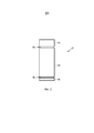
на фиг. 2 представлен схематически и в качестве примера вариант осуществления принимающего излучение пикселя принимающего излучение блока системы визуализации, иin FIG. 2 is a schematic and as an example embodiment of an radiation receiving pixel of a radiation receiving unit of a visualization system, and
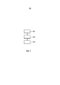
на фиг. 3 представлена блок-схема, в качестве примера иллюстрирующая вариант осуществления способа визуализации для визуализации объекта.in FIG. 3 is a flowchart illustrating an example embodiment of a visualization method for visualizing an object.
ОПИСАНИЕ ПРЕДПОЧТИТЕЛЬНЫХ ВАРИАНТОВ ОСУЩЕСТВЛЕНИЯDESCRIPTION OF PREFERRED EMBODIMENTS
На фиг. 1 схематически и в качестве примера представлена система визуализации области, представляющей интерес, которая представляет собой систему 19 компьютерной томографии. Система компьютерной томографии содержит портал 1, который может вращаться вокруг оси вращения R, которая идет параллельно направлению z. Источник 2 излучения, который в этом варианте осуществления представляет собой рентгеновскую трубку, устанавливают на портале 1. В источнике 2 излучения, который генерирует полихроматическое излучение, предусмотрен коллиматор 3, который формирует в этом варианте осуществления конический пучок 4 излучения из излучения, генерируемого посредством источника 2 излучения. Излучение проходит через объект, такой как пациент, в исследуемой зоне 5, которая в этом варианте осуществления является цилиндрической. После прохождения через исследуемую зону 5, пучок 4 излучения падает на принимающий излучение блок 6, который содержит двухмерную поверхность обнаружения. Принимающий излучение блок 6 установлен на портале 1.In FIG. 1 schematically and as an example, a visualization system of an area of interest is presented, which is a computed
Система 19 компьютерной томографии содержит два двигателя 7, 8. Портал 1 приводят в движение с предпочтительно постоянной, но корректируемой угловой скоростью посредством двигателя 7. Двигатель 8 предусмотрен для смещения объекта, например, пациента, который расположен на столе пациента в исследуемой зоне 5, параллельно направлению оси вращения R или оси z. Этими двигателями 7, 8 управляет блок 9 управления, например, так, что источник 2 излучения и исследуемая зона 5, в частности, объект внутри исследуемой зоны 5, перемещают друг относительно друга вдоль спиральной траектории. Однако также возможно, что объект не перемещают, а только вращают источник 2 излучения, т.е. что источник 2 излучения двигается по круговой траектории относительной исследуемой зоны 5, в частности, относительно объекта. Кроме того, в другом варианте осуществления коллиматор 3 можно адаптировать для формирования другой геометрической формы пучка, в частности, веерного пучка, и принимающий излучение блок 6 может содержать поверхность обнаружения, которой придают геометрическую форму, соответствующую другой геометрической форме пучка, в частности, соответствующую веерному пучку.The computed
Принимающий излучение блок 6 содержит несколько принимающих излучение пикселей 17, из которых один схематически и в качестве примера представлен на фиг. 2. Принимающий излучение пиксель 17 содержит первый сцинтиллятор 14 для генерации первого света сцинтилляции в зависимости от обнаруживаемого излучения и второй сцинтиллятор 15 для генерации второго света сцинтилляции в зависимости от обнаруживаемого излучения, где первый свет сцинтилляции соответствует первому времени спада, которое больше чем второе время спада, которому соответствует второй свет сцинтилляции, т.е. первый свет сцинтилляции и второй свет сцинтилляции имеют различные характеры поведения во времени, которые отличаются различными постоянными времени спада. Принимающий излучение пиксель 17 дополнительно содержит блок 16 обнаружения света сцинтилляции для обнаружения первого света сцинтилляции и второго света сцинтилляции и для генерации общего сигнала обнаружения света, который описывает первый свет сцинтилляции и второй свет сцинтилляции. Первый сцинтиллятор 14, второй сцинтиллятор 15 и блок 16 обнаружения света сцинтилляции оптически связаны так, что оба, первый свет сцинтилляции и второй свет сцинтилляции, можно совместно обнаруживать посредством блока 16 обнаружения света сцинтилляции. Блок 16 обнаружения света сцинтилляции предпочтительно представляет собой фотодиод, который адаптирован для обнаружения первого света сцинтилляции и второго света сцинтилляции. Фотодиод достаточно быстр для разрешения импульсов относительно короткого второго света сцинтилляции по времени.The
Первый сцинтиллятор 14, второй сцинтиллятор 15 и второй блок 16 обнаружения света формируют пакет так, что второй сцинтиллятор 15 располагают на блоке 16 обнаружения света сцинтилляции, а первый сцинтиллятор 14 располагают на втором сцинтилляторе 15, где первый сцинтиллятор 14, второй сцинтиллятор 15 и блок 16 обнаружения света сцинтилляции оптически связаны посредством использования оптического соединительного материала 18, который в этом варианте осуществления представляет собой оптически прозрачный клей, который прозрачен для первого света сцинтилляции и второго света сцинтилляции.The
Первый и второй сцинтилляторы 14, 15 адаптируют так, что интенсивности первого света сцинтилляции и второго света сцинтилляции схожи или различаются не более чем в десять раз. В частности, сцинтилляционные материалы, их допирование и их толщины адаптируют так, что выполняют это условие сходства в отношении интенсивностей первого света сцинтилляции и второго света сцинтилляции, в частности, в пределах типичного энергетического диапазона рентгеновских лучей, например, от 40 до 140 кэВ.The first and
Во время относительного движения источника 2 излучения и объекта в пределах исследуемой зоны 5, принимающий излучение блок 6 совместно обнаруживает первый свет сцинтилляции и второй свет сцинтилляции и генерирует общий сигнал обнаружения света, который описывает первый свет сцинтилляции и второй свет сцинтилляции.During the relative movement of the
Генерируемый общий сигнал обнаружения света предоставляют блоку 12 определения обнаруживаемых значений для определения первого обнаруживаемого значения и второго обнаруживаемого значения. Блок 12 определения обнаруживаемых значений адаптируют для того, чтобы определять первое обнаруживаемое значение посредством применения первого процесса определения к общему сигналу обнаружения света, где первый процесс определения включает в себя частотную фильтрацию общего сигнала обнаружения света посредством использования первого частотного фильтра, тем самым генерируя первый фильтрованный общий сигнал обнаружения света, и определения первого обнаруживаемого значения в зависимости от первого фильтрованного общего сигнала обнаружения света. Блок определения обнаруживаемых значений дополнительно адаптируют для того, чтобы определять второе обнаруживаемое значение посредством применения второго процесса определения к общему сигналу обнаружения света, причем второй процесс определения отличается от первого процесса определения. В этом варианте осуществления первый частотный фильтр представляет собой фильтр высоких частот или полосовой фильтр, и первый процесс определения включает a) возведение в квадрат или выпрямление первого фильтрованного по частоте общего сигнала обнаружения света, b) интегрирование возведенного в квадрат или выпрямленного первого фильтрованного по частоте общего сигнала обнаружения света, тем самым генерируя первое интегрированное значение, и c) определение первого обнаруживаемого значения в зависимости от первого интегрированного значения. Второй процесс определения включает a) частотную фильтрацию общего сигнала обнаружения света посредством использования второго частотного фильтра, тем самым генерируя второй фильтрованный общий сигнал обнаружения света, и b) определение второго обнаруживаемого значения в зависимости от второго фильтрованного общего сигнала обнаружения света, где второй частотный фильтр представляет собой фильтр низких частот.The generated common light detection signal is provided to the detectable
Предпочтительно, используют фильтр высоких частот, который подавляет частоты меньше среднего значения обратного значения постоянных времени спада первого и второго света сцинтилляции. В частности, фильтр высоких частот можно адаптировать для того, чтобы подавлять частоты меньше геометрического среднего обратного значения первой постоянной времени спада первого света сцинтилляции и обратного значения второй постоянной времени спада второго света сцинтилляции. Полосовой фильтр можно адаптировать для того, чтобы также подавлять частоты меньше среднего значения обратного значения первой постоянной времени спада и обратного значения второй постоянной времени спада, и полосовой фильтр можно адаптировать для того, чтобы подавлять частоты, которые больше чем десять раз превышают обратную вторую постоянную времени спада, где допустимо, что вторая постоянная времени спада меньше первой постоянной времени спада. Фильтр низких частот предпочтительно адаптируют для того, чтобы подавлять частоты больше среднего значения обратного значения первой постоянной времени спада первого света сцинтилляции и обратного значения второй постоянной времени спада второго света сцинтилляции. Среднее значение предпочтительно представляет собой геометрическое среднее значение.Preferably, a high-pass filter is used that suppresses frequencies less than the average of the inverse of the decay time constants of the first and second scintillation light. In particular, the high-pass filter can be adapted in order to suppress frequencies less than the geometric mean inverse of the first decay time constant of the first scintillation light and the inverse of the second decay time constant of the second scintillation light. The band-pass filter can be adapted to also suppress frequencies less than the average of the inverse of the first decay time constant and the inverse of the second decay time constant, and the band-pass filter can be adapted to suppress frequencies that are more than ten times the inverse second time constant recession, where it is permissible that the second recession time constant is less than the first recession time constant. The low-pass filter is preferably adapted to suppress frequencies greater than the average of the inverse of the first decay time constant of the first scintillation light and the inverse of the second decay time constant of the second scintillation light. The average value is preferably a geometric mean value.
Предпочтительно для каждого положения источника 2 излучения относительно объекта внутри исследуемой зоны 5 и для каждого принимающего излучение пикселя 17 блок определения обнаруживаемых значений определяет первое обнаруживаемое значение и второе обнаруживаемое значение, соответственно.Preferably, for each position of the
Первое и второе обнаруживаемые значения, которые определены для каждого положения источника 2 излучения относительно объекта внутри исследуемой зоны 5 и для каждого принимающего излучение пикселя 17, представляют в реконструирующий блок 10 для реконструкции изображения объекта на основе первого и второго обнаруживаемых значений. Изображение, реконструируемое посредством реконструирующего блока 10, предоставляют блоку 11 отображения для отображения реконструированного изображения.The first and second detectable values, which are determined for each position of the
Блок 9 управления предпочтительно также адаптируют для того, чтобы управлять источником 2 излучения, принимающим излучение блоком 6, блоком 12 определения обнаруживаемых значений и реконструирующим блоком 10. Поскольку принимающий излучение блок 6 и блок 12 определения обнаруживаемых значений генерируют первые и вторые обнаруживаемые значения на основе излучения, падающего на поверхность обнаружения принимающего излучение блока, принимающий излучение блок и блок определения обнаруживаемых значений можно рассматривать в качестве аппарата для обнаружения, чтобы обнаруживать излучение.The
Реконструирующий блок 10 предпочтительно адаптируют для того, чтобы раскладывать первое и второе обнаруживаемые значения на различные составляющие обнаруживаемые значения, которые соответствуют различным компонентам объекта. Эти различные компоненты, например, связаны с различными физическими эффектами, такими как эффект Комптона и фотоэлектрический эффект, и/или различные компоненты можно связывать с различными материалами, такими как кость, мягкие ткани человека и так далее. В этом варианте осуществления первое и второе обнаруживаемые значения трансформируют в промежуточные обнаруживаемые значения, которые соответствуют интенсивностям первого и второго света сцинтилляции. Преобразование предпочтительно представляет собой линейное преобразование, которое можно определять посредством калибровочных измерений. Например, излучение, создающее известные интенсивности света сцинтилляции, можно обнаруживать посредством аппарата для обнаружения, где преобразование можно определять на основе известных интенсивностей света сцинтилляции и первого и второго обнаруживаемых значений, генерируемых посредством аппарата для обнаружения. Реконструирующий блок 10 можно адаптировать для того, чтобы применять способ разложения, раскрытый в публикации «Energy-selective reconstructions in X-ray computerized tomography» R.E. Alvarez et al., Physics in Medicine and Biology, том 21, номер 5, страницы с 733 до 744 (1976), к промежуточным обнаруживаемым значениям.The reconstructing
В одном из вариантов осуществления разложение промежуточных обнаруживаемых значений осуществляют в соответствии со следующим уравнением, которое основано на инверсии физической модели, описывающей процесс измерения:In one embodiment, the decomposition of the intermediate detectable values is carried out in accordance with the following equation, which is based on the inversion of the physical model that describes the measurement process:

где Ci при i=1, 2 обозначает первое и второе промежуточные обнаруживаемые значения, Bi(E) обозначает спектральную чувствительность i-го измерения, которая соответствует первому или второму промежуточному обнаруживаемому значению, соответственно, F(E) обозначает спектр источника излучения, j=1…M типично при M=2 представляет собой индекс для M различных компонентов, Aj обозначает линейный интеграл значений концентраций до j-го компонента и µj(Ε) обозначает спектральный коэффициент поглощения j-го компонента.where C i with i = 1, 2 denotes the first and second intermediate detectable values, B i (E) denotes the spectral sensitivity of the ith measurement, which corresponds to the first or second intermediate detectable value, respectively, F (E) denotes the spectrum of the radiation source, j = 1 ... M typically at M = 2 is an index for M different components, A j denotes the linear integral of the concentration values to the jth component, and μ j (Ε) denotes the spectral absorption coefficient of the jth component.
Если число спектрально отдельных измерений по меньшей мере равно числу компонентов, систему уравнений можно решать с использованием известных численных методов, где величины Bi(E), F(E) и µj(Ε) известны, и результаты решения системы уравнений представляют собой линейные интегралы Aj. Спектр излучения F(E) и спектральная чувствительность Bi(E) представляют собой характеристики системы визуализации и свойства считывания и известны, например, из соответствующих измерений. Спектральное поглощение µj(Ε) компонентов, например, спектральное поглощение кости и мягких тканей, также известно из измерений и/или из литературы.If the number of spectrally separate measurements is at least equal to the number of components, the system of equations can be solved using known numerical methods, where the quantities B i (E), F (E) and µ j (Ε) are known, and the results of solving the system of equations are linear integrals A j . The emission spectrum F (E) and spectral sensitivity B i (E) are the characteristics of the imaging system and the reading properties and are known, for example, from the corresponding measurements. The spectral absorption of μ j (Ε) components, for example, the spectral absorption of bone and soft tissue, is also known from measurements and / or from the literature.
Разложенные обнаруживаемые значения в этом варианте осуществления представляют собой разложенные проекционные данные, т.е. линейные интегралы Aj, каждый из которых можно использовать для реконструкции компьютерно-томографического изображения объекта так, что, например, для каждого компонента можно реконструировать составляющее изображение объекта. Например, можно реконструировать комптоновское составляющее изображение и фотоэлектрическое составляющее изображение. Для реконструкции изображения на основе проекционных данных можно использовать известные способы реконструкции, такие как обратное проецирование с фильтрацией, обратное преобразование Радона и так далее.The decomposed detected values in this embodiment are decomposed projection data, i.e. linear integrals A j , each of which can be used to reconstruct a computer-tomographic image of the object so that, for example, for each component, the component image of the object can be reconstructed. For example, it is possible to reconstruct the Compton component image and the photoelectric component image. To reconstruct an image based on projection data, known reconstruction methods can be used, such as reverse projection with filtering, inverse Radon transform, and so on.
В другом варианте осуществления реконструирующий блок можно адаптировать для того, чтобы непосредственно раскладывать первые и вторые обнаруживаемые значения, без осуществления преобразования для определения промежуточных обнаруживаемых значений. В этом случае, разложение можно осуществлять в соответствии со следующим уравнением:In another embodiment, the reconstructing unit may be adapted to directly decompose the first and second detected values, without performing a conversion to determine intermediate detected values. In this case, the decomposition can be carried out in accordance with the following equation:

где k=1, 2 обозначает первое или второе обнаруживаемое значение, соответственно, Sl(E) обозначает спектральную чувствительность l-го сцинтиллятора, а Pkl(E) можно определять с помощью следующих уравнений:where k = 1, 2 denotes the first or second detectable value, respectively, S l (E) denotes the spectral sensitivity of the l-th scintillator, and P kl (E) can be determined using the following equations:

Различные характеры поведения во времени первого и второго сцинтилляторов влияют на коэффициенты ckl. Эти коэффициенты можно определять посредством калибровочных измерений, посредством моделирования или аналитически.Different characters of the time behavior of the first and second scintillators affect the coefficients c kl . These coefficients can be determined through calibration measurements, through simulation, or analytically.
Поскольку величины Pkl(E), Sl(E), F(E) и µj(Ε) известны, систему уравнений можно решать известными численными способами, если число спектрально отдельных измерений по меньшей мере равно числу компонентов. Результаты решения системы уравнений представляют собой линейные интегралы Aj, которые можно использовать для реконструкции компьютерно-томографического изображения для каждого компонента объекта, как описано выше.Since the quantities P kl (E), S l (E), F (E), and μ j (Ε) are known, the system of equations can be solved by known numerical methods if the number of spectrally separate measurements is at least equal to the number of components. The results of solving the system of equations are linear integrals A j that can be used to reconstruct a CT scan for each component of the object, as described above.
В следующем варианте осуществления способ визуализации для визуализации объекта в качестве примера описан со ссылкой на блок-схему, представленную на фиг. 3.In a further embodiment, the visualization method for visualizing an object is described as an example with reference to the flowchart of FIG. 3.
На этапе 101 источник 2 излучения генерирует фотоны, которые имеют различные энергии, в то время как источник 2 излучения и объект перемещают относительно друг друга для того, чтобы позволить излучению проходить через объект в различных направлениях. В частности, источник 2 излучения перемещают вдоль круговой или спиральной траектории вокруг объекта, в то время как первый сцинтиллятор генерирует первый свет сцинтилляции в зависимости от излучения и второй сцинтиллятор генерирует второй свет сцинтилляции в зависимости от излучения. Первый свет сцинтилляции и второй свет сцинтилляции обнаруживают и общий сигнал обнаружения света, который описывает первый свет сцинтилляции и второй свет сцинтилляции, генерируют посредством блока обнаружения света сцинтилляции. Кроме того, первое обнаруживаемое значение определяют посредством применения первого процесса определения к общему сигналу обнаружения света, где первый процесс определения включает в себя частотную фильтрацию общего сигнала обнаружения света посредством использования первого частотного фильтра, тем самым генерируя первый фильтрованный общий сигнал обнаружения света, и определения первого обнаруживаемого значения в зависимости от первого фильтрованного общего сигнала обнаружения света. Второе обнаруживаемое значение определяют посредством применения второго процесса определения к общему сигналу обнаружения света, где второй процесс определения отличается от первого процесса определения.At
На этапе 102 первое и второе обнаруживаемые значения, которые определены для каждого пространственного положения источника излучения относительно объекта и для каждого принимающего излучение пикселя, предоставляют реконструирующему блоку, и изображение объекта реконструируют на основе первого и второго обнаруживаемых значений посредством использования, например, алгоритма компьютерно-томографической реконструкции, такого как алгоритм обратного проецирования с фильтрацией. На этапе 103 реконструированное изображение показывают на блоке отображения.At
Генерацию первого и второго света сцинтилляции, обнаружение первого света сцинтилляции и второго света сцинтилляции, генерацию общего сигнала обнаружения света и определение первого обнаруживаемого значения и второго обнаруживаемого значения на основе общего сигнала обнаружения света, осуществляемые на этапе 101, можно рассматривать в качестве этапов способа обнаружения для обнаружения излучения.The generation of the first and second scintillation light, the detection of the first scintillation light and the second scintillation light, the generation of the common light detection signal and the determination of the first detectable value and the second detectable value based on the common light detection signal carried out in
Описанный выше аппарат для обнаружения представляет собой систему двухслойных детекторов, которая работает с использованием одного стандартного фотодиода и которую можно адаптировать для того, чтобы сделать возможным разделение сигналов, поступающих от переднего и заднего сцинтилляторов.The detection apparatus described above is a system of two-layer detectors that operates using one standard photodiode and which can be adapted in order to make it possible to separate signals from the front and rear scintillators.
Первый сцинтиллятор представляет собой относительно медленный сцинтиллятор, который имеет первое время спада, например, приблизительно 3 мкс, и второй сцинтиллятор представляет собой относительно быстрый сцинтиллятор, который имеет время спада, например, приблизительно 50 нс или меньше. Первый сцинтиллятор, например, представляет собой сцинтиллятор на оксисульфиде гадолиния (GOS), а второй сцинтиллятор, например, представляет собой сцинтиллятор на основе граната. Первый сцинтиллятор и второй сцинтиллятор можно рассматривать в качестве образующих верхний и нижний слои сцинтилляторов, которые оптически связаны, где оптические сигналы, генерируемые посредством верхнего и нижнего слоев сцинтилляторов, можно совместно считывать посредством блока обнаружения света сцинтилляции, который предпочтительно представляет собой быстрый фотодиод. Постоянная времени спада медленного сцинтиллятора может быть в диапазоне от 200 нс 3 мкс, а постоянная времени спада быстрого сцинтиллятора может быть в диапазоне от 5 до 100 нс.The first scintillator is a relatively slow scintillator that has a first decay time, for example, about 3 μs, and the second scintillator is a relatively fast scintillator that has a decay time, for example, about 50 ns or less. The first scintillator, for example, is a gadolinium oxysulfide scintillator (GOS), and the second scintillator, for example, is a garnet based scintillator. The first scintillator and the second scintillator can be considered as forming the upper and lower layers of scintillators, which are optically coupled, where the optical signals generated by the upper and lower layers of the scintillators can be read together by the scintillation light detection unit, which is preferably a fast photodiode. The decay time constant of the slow scintillator can be in the range from 200 ns to 3 μs, and the decay time constant of the fast scintillator can be in the range from 5 to 100 ns.
Аппарат для обнаружения, описанный выше со ссылкой на фиг. 1 и 2, преодолевают проблему обязательного оптического разделения переднего и заднего сцинтилляторов и необходимость фотодиодов бокового наблюдения. Оба аспекта могут снижать стоимость детекторов за счет значительного упрощения процесса изготовления детекторов.The detection apparatus described above with reference to FIG. 1 and 2 overcome the problem of the obligatory optical separation of the front and rear scintillators and the need for lateral observation photodiodes. Both aspects can reduce the cost of detectors by greatly simplifying the manufacturing process of detectors.
Фототок в фотодиоде предпочтительно идет короткими импульсами от быстрого сцинтиллятора и более длинными импульсами от более медленного сцинтиллятора. Аппарат для обнаружения предпочтительно адаптируют так, что мощности, вкладываемые двумя сигналами, находятся в достаточно разделенных частотных режимах, так что различные полосовые фильтры, адаптированные к постоянным времени спада, делают возможным количественное определение количества света сцинтилляции, берущего начало из двух слоев детектора. Блок определения обнаруживаемых значений предпочтительно адаптируют для того, чтобы выполнять разделение сигнала посредством фильтров, в частности, в частотно-временной области, которая выбирает быстрые или медленные компоненты в сигнале, т.е. в общем сигнале обнаружения света, после дублирования и, таким образом, делает возможным количественное определение общей мощности света, выходящего из верхнего и нижнего слоев отдельно, несмотря на обнаружение в одном фотодиоде. Блок обнаружения света сцинтилляции предпочтительно дополнительно содержит интеграторы для интегрирования сигнала после фильтра низких частот и сигнала после фильтра высоких частот, соответственно.The photocurrent in the photodiode preferably comes in short pulses from a fast scintillator and longer pulses from a slower scintillator. The detection apparatus is preferably adapted so that the powers input by the two signals are in sufficiently separated frequency modes, so that various bandpass filters adapted to the decay time constants make it possible to quantify the amount of scintillation light originating from two layers of the detector. The detecting value determination unit is preferably adapted to perform signal separation by filters, in particular in the time-frequency domain, which selects fast or slow components in the signal, i.e. in the general light detection signal, after duplication, and thus makes it possible to quantify the total power of the light coming from the upper and lower layers separately, despite detection in a single photodiode. The scintillation light detection unit preferably further comprises integrators for integrating the signal after the low-pass filter and the signal after the high-pass filter, respectively.
Блок обнаружения света сцинтилляции, в частности, фотодиод, должен обеспечивать флуктуацию обоих сцинтилляторов и, таким образом, должен быть достаточно быстрым. Фотодиод представляет собой, например, кремниевый PIN фотодиод. Фотодиод предпочтительно адаптируют для работы в полосе частот, например, до 1 ГГц.The scintillation light detection unit, in particular, the photodiode, must ensure the fluctuation of both scintillators and, thus, should be sufficiently fast. A photodiode is, for example, a silicon PIN photodiode. The photodiode is preferably adapted to operate in a frequency band, for example, up to 1 GHz.
В одном из вариантов осуществления первый процесс определения адаптируют для частотной фильтрации общего сигнала обнаружения света так, что первый фильтрованный общий сигнал обнаружения света представляет собой меняющийся уровень общего сигнала обнаружения света, тогда как второй процесс определения адаптируют так, что применение второго процесса определения к общему сигналу обнаружения света дает постоянный уровень общего сигнала обнаружения света. Первый процесс определения можно адаптировать для возведения квадрат или выпрямления меняющегося уровня, который также можно рассматривать в качестве уровня переменного тока общего сигнала обнаружения света, и для того, чтобы интегрировать возведенный в квадрат или выпрямленный меняющийся уровень для определения первого обнаруживаемого значения. Кроме того, второй процесс определения можно адаптировать для того, чтобы интегрировать постоянный уровень, который также можно рассматривать в качестве уровня постоянного тока общего сигнала обнаружения света, для определения второго обнаруживаемого значения.In one embodiment, the first determination process is adapted for frequency filtering the common light detection signal so that the first filtered common light detection signal is a varying level of the general light detection signal, while the second determination process is adapted so that applying the second determination process to the common signal light detection gives a constant level of the overall light detection signal. The first determination process can be adapted to square or rectify a varying level, which can also be considered as the AC level of a common light detection signal, and to integrate a squared or rectified varying level to determine the first detectable value. In addition, the second determination process can be adapted in order to integrate a constant level, which can also be considered as a constant current level of a common light detection signal, to determine a second detectable value.
Блок определения обнаруживаемых значений можно адаптировать для того, чтобы обрабатывать исходно аналоговый общий сигнал обнаружения света, или для того, чтобы оцифровывать общий сигнал обнаружения света, и для того, чтобы обрабатывать оцифрованный общий сигнал обнаружения света.The detecting value determination unit may be adapted to process an initially analogue common light detection signal, or to digitize a common light detection signal, and to process a digitized common light detection signal.
Несмотря на то что в описанных выше вариантах осуществления блок определения обнаруживаемых значений, который содержит, например, фильтры низких и высоких частот и интеграторы, не расположен на портале 1, в других вариантах осуществления блок определения обнаруживаемых значений, в частности, фильтры и интеграторы, также можно располагать на портале 1 близко, в частности, смежно с принимающим излучение блоком.Despite the fact that in the embodiments described above, the detected value determination unit, which contains, for example, low and high frequency filters and integrators, is not located on the portal 1, in other embodiments, the detected value determination unit, in particular filters and integrators, also can be located on the portal 1 close, in particular, adjacent to the radiation receiving unit.
Несмотря на то что в описанных выше вариантах осуществления аппарат для обнаружения описан как адаптированный для использования в системе компьютерной томографии, в других вариантах осуществления аппарат для обнаружения также можно адаптировать для использования в других системах визуализации, таких как системы радионуклидной визуализации, например, однофотонных эмиссионных компьютерных томографических или позитронно-эмиссионных томографических системах визуализации, или системах рентгеновской визуализации с C-образной рамой.Although in the above embodiments, the detection apparatus is described as adapted for use in a computed tomography system, in other embodiments, the detection apparatus can also be adapted for use in other imaging systems, such as radionuclide imaging systems, for example, single-photon emission computer tomographic or positron emission tomographic imaging systems, or X-ray imaging systems with a C-shaped frame.
Несмотря на то что в описанных выше вариантах осуществления принимающий излучение блок содержит два сцинтиллятора, которые имеют различные постоянные времени спада, в других вариантах осуществления принимающий излучение блок также может содержать больше чем два сцинтиллятора, которые имеют различные постоянные времени спада, где блок определения обнаруживаемых значений можно адаптировать для того, чтобы определять несколько обнаруживаемых значений посредством применения больше чем двух различных процессов определения к общему сигналу обнаружения света. Например, для каждого сцинтиллятора можно использовать полосовой фильтр, который соответствует соответствующей постоянной времени спада, для фильтрации общего сигнала обнаружения света, где для каждого сцинтиллятора генерируют фильтрованный сигнал, необязательно возведенный в квадрат или выпрямленный и предпочтительно интегрированный для генерации обнаруживаемых значений, соответствующих сцинтилляторам. Несколько обнаруживаемых значений, соответствующих нескольким сцинтилляторам, затем можно использовать для определения составляющих обнаруживаемых значений, которые соответствуют больше чем двум компонентам. Например, компоненты могут соответствовать больше чем двум физическим эффектам, таким как эффект Комптона, фотоэлектрический эффект и эффект K-края.Although in the above embodiments, the radiation receiving unit comprises two scintillators that have different decay time constants, in other embodiments, the radiation receiving unit may also contain more than two scintillators that have different decay time constants, where the detectable value determination unit can be adapted to determine several detectable values by applying more than two different determination processes to the total Nalu light detection. For example, for each scintillator, you can use a band-pass filter that corresponds to the corresponding decay time constant to filter the overall light detection signal, where a filtered signal is generated for each scintillator, optionally squared or rectified and preferably integrated to generate detectable values corresponding to the scintillators. Several detectable values corresponding to several scintillators can then be used to determine the components of the detectable values that correspond to more than two components. For example, components can correspond to more than two physical effects, such as the Compton effect, the photoelectric effect, and the K-edge effect.
Другие вариации раскрытых вариантов осуществления могут понять и реализовать специалисты в данной области при практическом осуществлении описываемого в заявке изобретения, изучив рисунки, раскрытие и приложенную формулу изобретения.Other variations of the disclosed embodiments may be understood and realized by those skilled in the art in practicing the invention described in the application, having studied the drawings, disclosure and appended claims.
В формуле изобретения слово «содержит» не исключает другие элементы или этапы, а формы единственного числа не исключают множество.In the claims, the word “contains” does not exclude other elements or steps, and the singular does not exclude a plurality.
Один блок или устройство может выполнять функции нескольких элементов, перечисленных в формуле изобретения. Сам факт того, что определенные средства перечислены во взаимно различных зависимых пунктах формулы изобретения, не указывает на то, что комбинация этих мер не может быть использована с пользой.A single unit or device can fulfill the functions of several elements listed in the claims. The mere fact that certain agents are listed in mutually different dependent claims does not indicate that a combination of these measures cannot be used to advantage.
Операции, такие как операции фильтрования и операции интегрирования, осуществляемые посредством одного или нескольких блоков или устройств, можно осуществлять посредством какого-либо другого числа блоков или устройств. Эти операции и/или управление системой визуализации в соответствии со способом визуализации и/или управление аппаратом для обнаружения в соответствии со способом обнаружения можно реализовать в качестве средства программного кода компьютерной программы и/или в качестве специализированного аппаратного обеспечения.Operations, such as filtering operations and integration operations carried out by one or more blocks or devices, can be performed by any other number of blocks or devices. These operations and / or control of the visualization system in accordance with the visualization method and / or control of the detection apparatus in accordance with the detection method can be implemented as a means of program code of a computer program and / or as specialized hardware.
Компьютерную программу можно хранить/распространять в подходящем носителе, таком как оптический запоминающий носитель или твердотельный носитель, поставляемый вместе с или в качестве части другого аппаратного обеспечения, но также можно распространять в других формах, например, через Интернет или другие проводные или беспроводные телекоммуникационные системы.The computer program can be stored / distributed in a suitable medium, such as optical storage medium or solid state media, supplied with or as part of other hardware, but can also be distributed in other forms, for example, via the Internet or other wired or wireless telecommunication systems.
Любые ссылочные позиции в формуле изобретения не следует толковать в качестве ограничения объема.Any reference position in the claims should not be construed as limiting the scope.
Изобретение относится к аппарату для обнаружения, чтобы обнаруживать излучение. Аппарат для обнаружения содержит по меньшей мере два сцинтиллятора, которые имеют различные характеры поведения во времени, каждый генерирует свет сцинтилляции после приема излучения, где генерируемый свет сцинтилляции обыкновенно обнаруживают посредством блока обнаружения света сцинтилляции, тем самым генерируя общий сигнал обнаружения света. Блок определения обнаруживаемых значений определяет первые обнаруживаемые значения посредством применения первого процесса определения и вторые обнаруживаемые значения посредством применения второго процесса определения, который отличается от первого процесса определения, к обнаруживаемому сигналу. Первый процесс определения включает в себя частотную фильтрацию обнаруживаемого сигнала. Поскольку свет сцинтилляции различных сцинтилляторов совместно обнаруживают посредством одного и того же блока обнаружения света сцинтилляции, установки для обнаружения с использованием, например, фотодиодов бокового наблюдения для отдельного обнаружения различного света сцинтилляции различных сцинтилляторов, более не требуются, тем самым снижая техническую сложность аппарата для обнаружения.The invention relates to an apparatus for detecting to detect radiation. The detection apparatus comprises at least two scintillators that have different patterns of behavior over time, each generating scintillation light after receiving radiation, where the generated scintillation light is usually detected by the scintillation light detection unit, thereby generating a common light detection signal. The detectable value determination unit determines the first detectable values by applying the first determination process and the second detectable values by applying the second determination process, which is different from the first determination process, to the detected signal. The first determination process includes frequency filtering of the detected signal. Since the scintillation light of different scintillators is jointly detected by the same scintillation light detection unit, installations for detecting using, for example, lateral observation photodiodes to separately detect different scintillation light of different scintillators, are no longer required, thereby reducing the technical complexity of the detection apparatus.
Claims (15)
принимающий излучение блок (6), включающий в себя:
первый сцинтиллятор (14) для генерации первого света сцинтилляции в зависимости от излучения, где первый свет сцинтилляции имеет первый характер поведения во времени,
второй сцинтиллятор (15) для генерации второго света сцинтилляции в зависимости от излучения, где второй свет сцинтилляции имеет второй характер поведения во времени, который отличается от первого характера поведения во времени,
блок (16) обнаружения света сцинтилляции для обнаружения первого света сцинтилляции и второго света сцинтилляции и для генерации общего сигнала обнаружения света, который указывает первый свет сцинтилляции и второй свет сцинтилляции,
блок (12) определения обнаруживаемых значений для определения первого обнаруживаемого значения и второго обнаруживаемого значения, причем блок (12) определения обнаруживаемых значений выполнен с возможностью:
определения первого обнаруживаемого значения посредством применения первого процесса определения к общему сигналу обнаружения света, причем первый процесс определения включает в себя частотную фильтрацию общего сигнала обнаружения света посредством использования первого частотного фильтра, тем самым генерируя первый фильтрованный общий сигнал обнаружения света, и определения первого обнаруживаемого значения в зависимости от первого фильтрованного общего сигнала обнаружения света,
определения второго обнаруживаемого значения посредством применения второго процесса определения к общему сигналу обнаружения света, причем второй процесс определения отличается от первого процесса определения.1. An apparatus for detecting radiation, the apparatus (6, 12) for detecting, comprising:
a radiation receiving unit (6), including:
the first scintillator (14) for generating the first scintillation light depending on the radiation, where the first scintillation light has a first behavior in time,
a second scintillator (15) for generating a second scintillation light depending on the radiation, where the second scintillation light has a second behavior in time, which differs from the first behavior in time,
a scintillation light detection unit (16) for detecting a first scintillation light and a second scintillation light and for generating a common light detection signal that indicates a first scintillation light and a second scintillation light,
a detecting value determination unit (12) for determining a first detectable value and a second detectable value, wherein the detectable value determination unit (12) is configured to:
determining the first detectable value by applying the first determination process to the common light detection signal, wherein the first determination process includes frequency filtering the common light detection signal by using the first frequency filter, thereby generating a first filtered common light detection signal, and determining the first detectable value in depending on the first filtered common light detection signal,
determining a second detectable value by applying the second determination process to a common light detection signal, the second determination process being different from the first determination process.
возведение в квадрат или выпрямление первого фильтрованного по частоте общего сигнала обнаружения света,
интегрирование возведенного в квадрат или выпрямленного первого фильтрованного по частоте общего сигнала обнаружения света, тем самым генерируя первое интегрированное значение, и
определение первого обнаруживаемого значения в зависимости от первого интегрированного значения.4. The apparatus for detection according to claim 1, in which the first determination process includes:
squaring or rectifying the first frequency-filtered common light detection signal,
integrating a squared or rectified first frequency-filtered common light detection signal, thereby generating a first integrated value, and
determining the first detectable value depending on the first integrated value.
частотную фильтрацию общего сигнала обнаружения света посредством использования второго частотного фильтра, тем самым генерируя второй фильтрованный общий сигнал обнаружения света, и
определение второго обнаруживаемого значения в зависимости от второго фильтрованного общего сигнала обнаружения света.5. The apparatus for detection according to claim 1, in which the second determination process includes:
frequency filtering the common light detection signal by using a second frequency filter, thereby generating a second filtered common light detection signal, and
determining a second detectable value depending on the second filtered total light detection signal.
интегрирование второго фильтрованного общего сигнала обнаружения света, тем самым генерируя второе интегрированное значение, и
определение второго обнаруживаемого значения в зависимости от второго интегрированного значения.7. The apparatus for detection according to claim 5, in which the second determination process further includes:
integrating a second filtered common light detection signal, thereby generating a second integrated value, and
determining a second detectable value depending on the second integrated value.
интегрирование общего сигнала обнаружения света, тем самым генерируя второе интегрированное значение, и
определение второго обнаруживаемого значения в зависимости от второго интегрированного значения.8. The apparatus for detection according to claim 1, in which the second determination process includes:
integrating a common light detection signal, thereby generating a second integrated value, and
determining a second detectable value depending on the second integrated value.
аппарат (6, 12) для обнаружения излучения, на которое влияет объект, по п. 1,
реконструирующий блок (10) для реконструкции изображения объекта по первому и второму обнаруживаемым значениям.10. A visualization system for visualizing an object, the visualization system (19) comprising:
an apparatus (6, 12) for detecting radiation affected by an object according to claim 1,
reconstructing unit (10) for reconstructing an image of an object from the first and second detectable values.
генерируют первый свет сцинтилляции в зависимости от излучения посредством первого сцинтиллятора (14), причем первый свет сцинтилляции имеет первый характер поведения во времени,
генерируют второй свет сцинтилляции в зависимости от излучения посредством второго сцинтиллятора (15), причем второй свет сцинтилляции имеет второй характер поведения во времени, который отличается от первого характера поведения во времени,
обнаруживают первый свет сцинтилляции и второй свет сцинтилляции и генерируют общий сигнал обнаружения света, который указывает первый свет сцинтилляции и второй свет сцинтилляции посредством блока (16) обнаружения света сцинтилляции,
определяют первое обнаруживаемое значение и второе обнаруживаемое значение посредством блока (12) определения обнаруживаемых значений, причем блок (12) определения обнаруживаемых значений:
определяет первое обнаруживаемое значение посредством применения первого процесса определения к общему сигналу обнаружения света, причем первый процесс определения включает в себя частотную фильтрацию общего сигнала обнаружения света посредством использования первого частотного фильтра, тем самым генерируя первый фильтрованный общий сигнал обнаружения света, и определения первого обнаруживаемого значения в зависимости от первого фильтрованного общего сигнала обнаружения света,
определяет второе обнаруживаемое значение посредством применения второго процесса определения к общему сигналу обнаружения света, причем второй процесс определения отличается от первого процесса определения.12. A detection method for detecting radiation, wherein the detection method includes the steps of:
generating the first scintillation light depending on the radiation by the first scintillator (14), the first scintillation light having a first behavior in time,
generating a second scintillation light depending on the radiation by the second scintillator (15), the second scintillation light having a second behavior in time, which differs from the first behavior in time,
detecting the first scintillation light and the second scintillation light and generate a common light detection signal that indicates the first scintillation light and the second scintillation light by the scintillation light detection unit (16),
determining a first detectable value and a second detectable value by a detectable value determination unit (12), the detectable value determination unit (12):
determines the first detectable value by applying the first determination process to the common light detection signal, the first determination process including frequency filtering the common light detection signal by using the first frequency filter, thereby generating a first filtered common light detection signal, and determining the first detected value in depending on the first filtered common light detection signal,
determines the second detectable value by applying the second determination process to the overall light detection signal, the second determination process being different from the first determination process.
обнаруживают излучения, на которое влияет объект, по п. 12, реконструируют изображение объекта по первому и второму
обнаруживаемым значениям посредством реконструирующего блока (10).13. A visualization method for visualizing an object, wherein the visualization method includes the steps of:
detect the radiation affected by the object, according to claim 12, reconstruct the image of the object according to the first and second
detectable values by means of a reconstructing block (10).
Applications Claiming Priority (3)
| Application Number | Priority Date | Filing Date | Title |
|---|---|---|---|
| US201161566185P | 2011-12-02 | 2011-12-02 | |
| US61/566,185 | 2011-12-02 | ||
| PCT/IB2012/056663 WO2013080104A2 (en) | 2011-12-02 | 2012-11-23 | Detection apparatus for detecting radiation |
Publications (2)
| Publication Number | Publication Date |
|---|---|
| RU2014126858A RU2014126858A (en) | 2016-02-10 |
| RU2595796C2 true RU2595796C2 (en) | 2016-08-27 |
Family
ID=47594940
Family Applications (1)
| Application Number | Title | Priority Date | Filing Date |
|---|---|---|---|
| RU2014126858/28A RU2595796C2 (en) | 2011-12-02 | 2012-11-23 | Apparatus for detecting containing two scintillators for detecting x-ray radiation |
Country Status (8)
| Country | Link |
|---|---|
| US (1) | US9423514B2 (en) |
| EP (1) | EP2748636B1 (en) |
| JP (1) | JP6254947B2 (en) |
| CN (1) | CN103959097B (en) |
| BR (1) | BR112014012832A2 (en) |
| IN (1) | IN2014CN04519A (en) |
| RU (1) | RU2595796C2 (en) |
| WO (1) | WO2013080104A2 (en) |
Families Citing this family (11)
| Publication number | Priority date | Publication date | Assignee | Title |
|---|---|---|---|---|
| US9291724B2 (en) * | 2012-12-12 | 2016-03-22 | Koninklijke Philips N.V. | Adaptive persistent current compensation for photon counting detectors |
| DE102013112573A1 (en) * | 2013-11-14 | 2015-06-03 | Technische Universität Dresden | Scintillation detector with intrinsic suppression of escaping secondary particles |
| US10101471B2 (en) * | 2014-07-23 | 2018-10-16 | Koninklijke Philips N.V. | Characterization apparatus for characterizing scintillator material |
| US10899672B2 (en) * | 2014-09-25 | 2021-01-26 | Koninklijke Philips N.V. | Ceramic material for generating light |
| JP2016180625A (en) * | 2015-03-23 | 2016-10-13 | 株式会社東芝 | Radiation detection device, input-output calibration method and input-output calibration program |
| KR101831627B1 (en) * | 2016-04-05 | 2018-04-04 | 한국원자력연구원 | Plastic scintillator, method of menufacturing thereof, and detector for measurement of beta contamination level comprising the same |
| US11000701B2 (en) * | 2017-08-01 | 2021-05-11 | Varex Imaging Corporation | Dual-layer detector for soft tissue motion tracking |
| US11181488B2 (en) | 2017-08-31 | 2021-11-23 | Koninklijke Philips N.V. | Multi-layer detector with a monolithic scintillator |
| WO2019098629A1 (en) * | 2017-11-17 | 2019-05-23 | 고려대학교 산학협력단 | Radiation detector for detecting radiation and identifying type thereof |
| CN110187356B (en) * | 2019-06-14 | 2021-07-09 | 中国科学技术大学 | Remote super-resolution single photon imaging reconstruction method |
| US11726217B2 (en) | 2020-09-23 | 2023-08-15 | Luca Medical Systems, Inc. | Systems and methods for measuring and tracking energy emitted by a radiation source |
Citations (2)
| Publication number | Priority date | Publication date | Assignee | Title |
|---|---|---|---|---|
| US4870667A (en) * | 1985-08-29 | 1989-09-26 | Picker International, Inc. | Radiation detector |
| RU2384866C2 (en) * | 2005-04-22 | 2010-03-20 | Конинклейке Филипс Электроникс Н.В. | Positron emission tomography and magnetic resonance imaging scanner capable of determining time of flight |
Family Cites Families (20)
| Publication number | Priority date | Publication date | Assignee | Title |
|---|---|---|---|---|
| FR2621705B1 (en) | 1987-10-09 | 1990-03-30 | Thomson Csf | MULTI-RADIATION DETECTOR, IN PARTICULAR DOUBLE ENERGY X-RAY DETECTOR |
| JPH0587935A (en) * | 1991-09-27 | 1993-04-09 | Fuji Electric Co Ltd | Radiation measuring apparatus |
| US5317158A (en) * | 1991-10-22 | 1994-05-31 | Martin Marietta Energy Systems, Inc. | Unitary scintillation detector and system |
| JP2000056023A (en) * | 1998-08-06 | 2000-02-25 | Japan Science & Technology Corp | Pet detector capable of providing depth directional information |
| JP2000193749A (en) * | 1998-12-28 | 2000-07-14 | Toshiba Corp | alphabeta DETECTOR AND alphabeta DETECTING DEVICE USING IT |
| US6297506B1 (en) * | 2000-03-23 | 2001-10-02 | John W. Young | System and method for reducing pile-up errors in multi-crystal gamma ray detector applications |
| JP4480865B2 (en) * | 2000-08-07 | 2010-06-16 | 財団法人先端医療振興財団 | Scintillation detector and method for detecting beta plus line |
| US20020195565A1 (en) * | 2001-06-26 | 2002-12-26 | European Organization For Nuclear Research | PET scanner |
| DE10201995B4 (en) | 2002-01-21 | 2004-03-25 | Forschungszentrum Jülich GmbH | Method for assigning a pulse run to one of a plurality of pulse types with different decay times and device for carrying it out |
| US20060067472A1 (en) * | 2004-09-30 | 2006-03-30 | Possin George E | Method and apparatus for measuring X-ray energy |
| EP1899747A4 (en) * | 2005-07-01 | 2016-12-07 | Warburton William K | Detection of coincident radiations in a single transducer by pulse shape analysis |
| US7388208B2 (en) * | 2006-01-11 | 2008-06-17 | Ruvin Deych | Dual energy x-ray detector |
| DE102006017291B4 (en) * | 2006-02-01 | 2017-05-24 | Paul Scherer Institut | Focus / detector system of an X-ray apparatus for producing phase contrast recordings, X-ray system with such a focus / detector system and associated storage medium and method |
| EP2097771A2 (en) * | 2006-12-22 | 2009-09-09 | Koninklijke Philips Electronics N.V. | Energy-resolving detection system and imaging system |
| EP2115490A1 (en) * | 2007-02-09 | 2009-11-11 | University Of Wollongong | Dual radiation detector |
| US7683334B2 (en) * | 2007-08-07 | 2010-03-23 | The State Of Oregon Acting By And Through The State Board Of Higher Education On Behalf Of Oregon State University | Simultaneous beta and gamma spectroscopy |
| JP5320818B2 (en) * | 2007-09-25 | 2013-10-23 | 株式会社島津製作所 | Imaging apparatus and light source position calculation method |
| EP2296551B1 (en) * | 2008-06-30 | 2016-04-20 | Koninklijke Philips N.V. | Spectral ct |
| WO2010018475A2 (en) * | 2008-08-13 | 2010-02-18 | Koninklijke Philips Electronics, N.V. | Method and apparatus for detecting low and high x-ray flux |
| JP5423433B2 (en) * | 2010-01-28 | 2014-02-19 | 株式会社島津製作所 | Nuclear medicine diagnostic equipment |
-
2012
- 2012-11-23 BR BR112014012832A patent/BR112014012832A2/en not_active IP Right Cessation
- 2012-11-23 WO PCT/IB2012/056663 patent/WO2013080104A2/en active Application Filing
- 2012-11-23 IN IN4519CHN2014 patent/IN2014CN04519A/en unknown
- 2012-11-23 EP EP12816507.3A patent/EP2748636B1/en active Active
- 2012-11-23 US US14/359,311 patent/US9423514B2/en active Active
- 2012-11-23 RU RU2014126858/28A patent/RU2595796C2/en active
- 2012-11-23 JP JP2014544006A patent/JP6254947B2/en active Active
- 2012-11-23 CN CN201280058860.XA patent/CN103959097B/en active Active
Patent Citations (2)
| Publication number | Priority date | Publication date | Assignee | Title |
|---|---|---|---|---|
| US4870667A (en) * | 1985-08-29 | 1989-09-26 | Picker International, Inc. | Radiation detector |
| RU2384866C2 (en) * | 2005-04-22 | 2010-03-20 | Конинклейке Филипс Электроникс Н.В. | Positron emission tomography and magnetic resonance imaging scanner capable of determining time of flight |
Also Published As
| Publication number | Publication date |
|---|---|
| IN2014CN04519A (en) | 2015-09-11 |
| JP2015504521A (en) | 2015-02-12 |
| RU2014126858A (en) | 2016-02-10 |
| WO2013080104A2 (en) | 2013-06-06 |
| CN103959097A (en) | 2014-07-30 |
| EP2748636B1 (en) | 2020-09-02 |
| WO2013080104A3 (en) | 2013-08-08 |
| US20140306116A1 (en) | 2014-10-16 |
| US9423514B2 (en) | 2016-08-23 |
| CN103959097B (en) | 2017-05-10 |
| JP6254947B2 (en) | 2017-12-27 |
| EP2748636A2 (en) | 2014-07-02 |
| BR112014012832A2 (en) | 2017-06-13 |
Similar Documents
| Publication | Publication Date | Title |
|---|---|---|
| RU2595796C2 (en) | Apparatus for detecting containing two scintillators for detecting x-ray radiation | |
| RU2505268C2 (en) | Spectral computed tomography | |
| JP2015504521A5 (en) | ||
| RU2596715C2 (en) | Detection device | |
| CN102224435B (en) | Light spectrum image-forming | |
| RU2444764C2 (en) | Imaging system for object imaging | |
| CN103339497B (en) | Probe value treatment facility | |
| JP2016536032A (en) | Concatenated reconstruction of electron density images | |
| JP2006346460A (en) | Method for calculating weight coefficient to improve contrast noise ratio in x-ray image and method for improving contrast noise ratio | |
| JP6793469B2 (en) | Data processing equipment, X-ray CT equipment and data processing method | |
| CN109917445A (en) | The scattering of x-ray imaging estimates and/or correction | |
| JP2018057867A (en) | Medical image processing device, x-ray computer tomographic imaging device and medical image processing method | |
| US9924917B2 (en) | X-ray CT device and processing method | |
| JP2009201885A (en) | X-ray ct system | |
| US20170090039A1 (en) | Layered radiation detector | |
| Meng et al. | Energy window optimization for X-ray K-edge tomographic imaging | |
| US20160106386A1 (en) | Methods and systems for task-based data generation and weighting for ct spectral imaging | |
| CN107106109A (en) | Computed tomograph scanner system | |
| US9177397B2 (en) | Imaging apparatus | |
| US20100104161A1 (en) | Projection system for producing attenuation components | |
| Taguchi et al. | Image-domain material decomposition using photon-counting CT | |
| EP3326154B1 (en) | Method and apparatus for performing multi-energy (including dual energy) computed tomography (ct) imaging | |
| Kong et al. | Evaluation of an analytic reconstruction method as a platform for spectral cone-beam CT | |
| Szczykutowicz et al. | The dependence of image quality on the number of high and low kVp projections in dual energy CT using the prior image constrained compressed sensing (PICCS) algorithm | |
| JP2024515595A (en) | Determining confidence indicators for deep learning image reconstruction in computed tomography |