RU2585309C2 - System and method for radio relay communication with electronic control of beam - Google Patents
System and method for radio relay communication with electronic control of beam Download PDFInfo
- Publication number
- RU2585309C2 RU2585309C2 RU2014120000/28A RU2014120000A RU2585309C2 RU 2585309 C2 RU2585309 C2 RU 2585309C2 RU 2014120000/28 A RU2014120000/28 A RU 2014120000/28A RU 2014120000 A RU2014120000 A RU 2014120000A RU 2585309 C2 RU2585309 C2 RU 2585309C2
- Authority
- RU
- Russia
- Prior art keywords
- antenna
- transceiver
- transceiver system
- antennas
- directions
- Prior art date
Links
Images
Classifications
-
- H—ELECTRICITY
- H01—ELECTRIC ELEMENTS
- H01Q—ANTENNAS, i.e. RADIO AERIALS
- H01Q1/00—Details of, or arrangements associated with, antennas
- H01Q1/12—Supports; Mounting means
-
- H—ELECTRICITY
- H04—ELECTRIC COMMUNICATION TECHNIQUE
- H04B—TRANSMISSION
- H04B7/00—Radio transmission systems, i.e. using radiation field
- H04B7/14—Relay systems
- H04B7/15—Active relay systems
- H04B7/155—Ground-based stations
-
- H—ELECTRICITY
- H01—ELECTRIC ELEMENTS
- H01Q—ANTENNAS, i.e. RADIO AERIALS
- H01Q1/00—Details of, or arrangements associated with, antennas
- H01Q1/12—Supports; Mounting means
- H01Q1/125—Means for positioning
- H01Q1/1257—Means for positioning using the received signal strength
-
- H—ELECTRICITY
- H01—ELECTRIC ELEMENTS
- H01Q—ANTENNAS, i.e. RADIO AERIALS
- H01Q25/00—Antennas or antenna systems providing at least two radiating patterns
- H01Q25/007—Antennas or antenna systems providing at least two radiating patterns using two or more primary active elements in the focal region of a focusing device
-
- H—ELECTRICITY
- H01—ELECTRIC ELEMENTS
- H01Q—ANTENNAS, i.e. RADIO AERIALS
- H01Q3/00—Arrangements for changing or varying the orientation or the shape of the directional pattern of the waves radiated from an antenna or antenna system
- H01Q3/24—Arrangements for changing or varying the orientation or the shape of the directional pattern of the waves radiated from an antenna or antenna system varying the orientation by switching energy from one active radiating element to another, e.g. for beam switching
- H01Q3/245—Arrangements for changing or varying the orientation or the shape of the directional pattern of the waves radiated from an antenna or antenna system varying the orientation by switching energy from one active radiating element to another, e.g. for beam switching in the focal plane of a focussing device
Abstract
Description
Область техникиTechnical field
Изобретение в целом относится к области радиосвязи и, в частности, к системам связи типа "точка-точка" миллиметрового диапазона длин волн, обеспечивающим высокоскоростное соединение (системам радиорелейных станций - РРС). Изобретение представляет собой систему и способ радиорелейной связи с электронной подстройкой луча. Изобретение обеспечивает возможность как автоматической настройки лучей антенн двух РРС друг на друга при первичной юстировке, так и дальнейшей подстройки направлений лучей для компенсации небольших изменений ориентации антенн вследствие воздействия различных факторов (таких как ветер, вибрации, различный коэффициент расширения несущих конструкций вследствие изменения температуры, и т.д.).The invention as a whole relates to the field of radio communications and, in particular, to point-to-point communication systems of the millimeter wavelength range, providing high-speed connection (radio relay station systems - RRS). The invention is a system and method for microwave communication with electronic beam adjustment. The invention provides the possibility of both automatically adjusting the rays of the antennas of two RRS to each other during initial alignment, and further adjusting the directions of the rays to compensate for small changes in the orientation of the antennas due to various factors (such as wind, vibration, different expansion coefficient of the supporting structures due to temperature changes, and etc.).
Уровень техникиState of the art
Радиорелейные станции (РРС) типа "точка-точка" широко используются в различных транспортных сетях для множества приложений, одним из наиболее перспективных из которых являются транспортные сети между базовыми станциями сетей мобильной связи. Наблюдаемое в настоящее время увеличение объема передаваемых данных в сетях мобильной связи приводит к еще большим требованиям к пропускной способности радиоинтерфейсов таких сетей и, как следствие, к пропускной способности эксплуатируемых транспортных сетей. Ожидается, что требования по пропускной способности транспортных сетей для каждой базовой станции вырастут за ближайшие несколько лет с текущих нескольких Мб/с (или даже сотен Кб/с) до сотен или даже тысяч Мб/с.Point-to-point radio relay stations (RRS) are widely used in various transport networks for many applications, one of the most promising of which are transport networks between base stations of mobile communication networks. The currently observed increase in the volume of transmitted data in mobile communication networks leads to even greater demands on the bandwidth of the radio interfaces of such networks and, as a result, on the bandwidth of operating transport networks. It is expected that the bandwidth requirements for transport networks for each base station will increase over the next few years from the current several Mb / s (or even hundreds of Kb / s) to hundreds or even thousands of Mb / s.
Для того чтобы удовлетворить таким растущим требованиям к пропускной способности радиорелейных станций, необходимо увеличение ширины частотной полосы передаваемого сигнала, что позволит увеличить скорость передачи данных. Но, так как имеющийся частотный диапазон практически полностью используется различными радиоэлектронными системами, необходимо увеличение несущей частоты РРС и использование новых диапазонов. В частности, в спектре миллиметровых длин волн от 30 ГГц до 300 ГГц, имеющем значительный потенциал для разработки высокоскоростных транспортных радиорелейных сетей, обеспечивающих связь типа точка-точка, во многих странах мира были выделены полосы частот 71-76 ГГц и 81-86 ГГц с отсутствующей или упрощенной процедурой лицензирования.In order to satisfy such growing requirements for the capacity of radio relay stations, it is necessary to increase the frequency bandwidth of the transmitted signal, which will increase the data transfer rate. But, since the available frequency range is almost completely used by various electronic systems, it is necessary to increase the carrier frequency of the RRS and the use of new ranges. In particular, in the millimeter wavelength spectrum from 30 GHz to 300 GHz, which has significant potential for the development of high-speed transport radio relay networks providing point-to-point communication, in many countries of the world, frequency bands 71-76 GHz and 81-86 GHz with an absent or simplified licensing procedure.
Увеличение несущей частоты и ширины полосы пропускания сигнала оказывает сильное влияние на практическую разработку РРС. Принимаемая мощность сигнала на 1 Гц полосы частот должна оставаться такой же, как и в низкочастотных системах, для сохранения спектральной эффективности. Это приводит к требованию большей принимаемой мощности, что может быть достигнуто за счет увеличения передаваемой мощности или увеличения коэффициентов усиления антенн на передающей и/или приемной станциях. Мощность передатчика обычно лимитирована регуляторными ограничениями, что оставляет только возможность использования антенн с большим коэффициентом усиления. В то же самое время известная формула Фрииса (Н.Т. Friis, Proceedings of IRE, vol. 34, p. 254. 1946):An increase in the carrier frequency and signal bandwidth has a strong influence on the practical development of RRS. The received signal power at 1 Hz of the frequency band must remain the same as in low-frequency systems to maintain spectral efficiency. This leads to the requirement of a higher received power, which can be achieved by increasing the transmitted power or increasing the gain of the antennas at the transmitting and / or receiving stations. Transmitter power is usually limited by regulatory restrictions, which leaves only the possibility of using antennas with a large gain. At the same time, the famous Friis formula (N.T. Friis, Proceedings of IRE, vol. 34, p. 254. 1946):
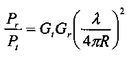
показывает, что принимаемая мощность Pr в свободном пространстве (что справедливо для РРС) пропорциональна коэффициентам усиления приемной Gr и передающей Gt антенн, переданной мощности Pt и квадрату длины волны λ на несущей частоте и обратно пропорциональна квадрату расстояния между антеннами R. Таким образом, переход к более высоким несущим частотам даже при сохранении частотной полосы пропускания также требует увеличения коэффициентов усиления антенн на приемнике и передатчике для обеспечения той же пропускной способности.shows that the received power P r in free space (which is true for RRS) is proportional to the gain of the receiving G r and transmitting G t antennas, the transmitted power P t and the square of the wavelength λ at the carrier frequency and inversely proportional to the square of the distance between the antennas R. Thus thus, moving to higher carrier frequencies even while maintaining the frequency bandwidth also requires increasing the antenna gains at the receiver and transmitter to ensure the same throughput.
Связанным с коэффициентом усиления антенны параметром является ширина основного луча диаграммы направленности (ДН) антенны по уровню половинной мощности, которая уменьшается с увеличением коэффициента усиления антенны. В соответствии с замечаниями, данными выше, коэффициент усиления антенн РРС миллиметрового диапазона длин волн обычно составляет 35-45 дБи, что эквивалентно ширине луча ДН антенны порядка 1-2° или меньше.A parameter related to the antenna gain is the width of the main beam of the antenna pattern at the half power level, which decreases with increasing antenna gain. In accordance with the comments above, the gain of the PPC antennas of the millimeter wavelength range is usually 35-45 dBi, which is equivalent to the beam width of the antenna beam of the order of 1-2 ° or less.
Использование в РРС антенн с таким узким основным лучом ДН приводит к дополнительным трудностям при их эксплуатации, которые не возникают в системах, работающих на меньших несущих частотах и использующих меньшую полосу пропускания. Устройства РРС с антеннами обычно устанавливаются вблизи базовых станций сетей передачи данных на различных высоких конструкциях, таких как вышки, башни, крыши высотных зданий. Обычно такие вышки являются жесткими металлическими конструкциями, которые, тем не менее, подвержены небольшим скручиваниям и отклонениям (особенно в их верхней части), вызванными ветром, различными коэффициентами расширения несущих конструкций вследствие нагрева/охлаждения в разное время суток и другими причинами. Высотные здания испытывают те же проблемы (хотя и в меньшей степени) вследствие небольших длительных смещений их фундаментов, что приводит к небольшим изменениям ориентации РРС, особенно установленных на вершине зданий.The use of antennas in RRS with such a narrow main beam of radiation leads to additional difficulties in their operation, which do not arise in systems operating at lower carrier frequencies and using a smaller bandwidth. RRS devices with antennas are usually installed near the base stations of data transmission networks on various tall structures, such as towers, towers, roofs of tall buildings. Typically, such towers are rigid metal structures, which, however, are subject to small twists and deviations (especially in their upper part) caused by wind, various expansion coefficients of the supporting structures due to heating / cooling at different times of the day, and other reasons. Tall buildings experience the same problems (albeit to a lesser extent) due to small long-term displacements of their foundations, which leads to small changes in the orientation of the RRS, especially those installed on top of the buildings.
Рассмотренные изменения ориентации конструкций, на которые установлены РРС, могут приводить к потере взаимной ориентации приемной и передающей антенн друг на друга и разрыву соединения. Данная проблема становится сейчас актуальной для миллиметровых РРС, в которых используются антенны с шириной луча менее 1-2° вследствие причин, рассмотренных выше.The considered changes in the orientation of the structures on which the RRS are installed can lead to a loss of the mutual orientation of the receiving and transmitting antennas to each other and to a disconnection. This problem is now becoming relevant for millimeter-wave RRSs that use antennas with a beam width of less than 1-2 ° due to the reasons discussed above.
Частотные и временные интервалы изменения ориентации РРС, установленных на различных конструкциях, сильно зависят от причины таких изменений. Вариации могут составлять от долей Гц (или даже нескольких Гц) для колебаний, вызванных ветром, до часов для отклонений вследствие нагрева солнцем различных частей конструкций и даже годов для небольших смещений фундаментов зданий.Frequency and time intervals of changes in the orientation of the RRS installed on various designs, strongly depend on the cause of such changes. Variations can range from fractions of a Hz (or even a few Hz) for vibrations caused by wind, to hours for deviations due to heating of various parts of structures by the sun and even years for small displacements of building foundations.
Используемые в настоящее время способы решения рассмотренной проблемы включают в себя установку РРС на более низких частях вышек и башен (а не на их верхней части), невысоких крышах зданий, а также механическую перенастройку антенн в случае медленных изменений их ориентаций.Currently used methods for solving the considered problem include installing RRS on the lower parts of towers and towers (and not on their upper parts), low roofs of buildings, as well as mechanical resetting of antennas in case of slow changes in their orientations.
Системы РРС для транспортных каналов сотовых систем связиPPC systems for transport channels of cellular communication systems
Системы радиорелейной связи широко используются для организации транспортных каналов в сотовых системах связи. В сравнении с традиционными оптоволоконными линиям связи, РРС обеспечивают значительно меньшие затраты на введение в эксплуатацию при достижении в последнее время сравнимой пропускной способности. Указанные преимущества стимулируют развитие технологий и техник для создания эффективных приемопередатчиков миллиметрового диапазона длин волн.Radio relay communication systems are widely used to organize transport channels in cellular communication systems. Compared to traditional fiber-optic communication lines, PPCs provide significantly lower commissioning costs when recently achieving comparable throughput. These advantages stimulate the development of technologies and techniques for creating efficient millimeter-wave transceivers.
В соответствии с вышесказанным в настоящее время предлагается множество вариантов и модернизаций систем связи типа точка-точка и точка-многоточка для транспортных каналов систем сотовой связи. Так, в патенте США №7,769,347 "Wireless communication system" рассматривается беспроводная система связи, обеспечивающая передачу данных между мобильными пользователями посредством множества сотовых базовых станций. При этом между базовыми станциями напрямую или с помощью дополнительных точек соединения устанавливаются линии связи в миллиметровом диапазоне длин волн выше 60 ГГц. Стоит отметить, что авторы изобретения особо выделяют диапазоны 71-76 ГГц и 81-86 ГГц, преимущества которых ранее были рассмотрены в настоящем описании. Также оговаривается, что антенна для такой радиорелейной связи должна обеспечивать узкий луч и высокий коэффициент усиления.In accordance with the foregoing, many options and upgrades of point-to-point and point-to-multipoint communication systems for transport channels of cellular communication systems are currently offered. So, in US patent No. 7,769,347 "Wireless communication system" describes a wireless communication system that provides data transfer between mobile users through multiple cellular base stations. In this case, communication lines in the millimeter wavelength range above 60 GHz are established directly between the base stations or with the help of additional connection points. It is worth noting that the inventors particularly highlight the ranges 71-76 GHz and 81-86 GHz, the advantages of which were previously discussed in the present description. It is also stipulated that the antenna for such radio relay communication should provide a narrow beam and a high gain.
В описании к рассматриваемому патенту США №7,769,347 особо подчеркивается важность точности настройки луча и приведены некоторые известные способы такой настройки.U.S. Pat. No. 7,769,347 describes the importance of beam alignment accuracy and provides some known methods for such alignment.
Способы настройки луча, рассмотренные в указанном патенте, включают в основном методы механического сканирования для больших зеркальных антенн и электронные методы сканирования с помощью фазированных антенных решеток. Однако реализация таких антенных решеток для миллиметровых РРС представляется непрактичной на сегодняшний день в силу требования большого количества синхронизованных антенных элементов. Рассмотренные современные способы механического сканирования включают как поворот всей антенны с помощью прецизионных механизмов, так и перемещение или вращение первичных облучателей больших зеркал, перемещение вторичного небольшого зеркала, например, в антенне Кассегрена, использование многоапертурных антенн совместно с решеткой переключаемых антенных элементов. Недостатками всех указанных методов механического сканирования являются длительность настройки и необходимость привлечения квалифицированного персонала для осуществления такой настройки.The beam tuning methods described in this patent mainly include mechanical scanning methods for large specular antennas and electronic scanning methods using phased array antennas. However, the implementation of such antenna arrays for millimeter-wave PPCs seems impractical today due to the requirement of a large number of synchronized antenna elements. The considered modern methods of mechanical scanning include both turning the entire antenna using precision mechanisms, and moving or rotating the primary irradiators of large mirrors, moving a secondary small mirror, for example, in a Cassegrain antenna, using multi-aperture antennas in conjunction with a array of switched antenna elements. The disadvantages of all these methods of mechanical scanning are the duration of the setup and the need to attract qualified personnel to implement such a setup.
Вариант реализации системы РРС представлен, например, в заявке на патент США №20080153549 "Wireless millimeter wave communication system". В частности в данной патентной заявке описан полнодуплексный приемопередатчик для РРС рассматриваемых частотных диапазонов 71-76 ГГц и 81-86 ГГц, в котором в качестве антенны используется линзовая антенна с вынесенным облучателем в виде рупорной антенны. Применение линзовой антенны в данном случае обеспечивает меньший уровень боковых лепестков по сравнению с традиционными для данного приложения зеркальными антеннами. Также в описании отдельно уделяется внимание грубой и точной настройкам антенн друг на друга, однако никаких решений для реализации такой настройки не предлагается.An embodiment of a PPC system is presented, for example, in US Patent Application No. 20080153549 "Wireless millimeter wave communication system". In particular, this patent application describes a full-duplex transceiver for RRS of the considered frequency ranges 71-76 GHz and 81-86 GHz, in which a lens antenna with a remote irradiator in the form of a horn antenna is used as an antenna. The use of a lens antenna in this case provides a lower level of side lobes compared to traditional for this application mirror antennas. Also in the description, special attention is paid to the rough and precise settings of the antennas for each other, however, no solutions are proposed for implementing such a configuration.
Достаточно большое число способов грубой и точной настройки положения луча известно из других источников в уровне техники. Грубая настройка осуществляется с помощью некоторых простых, но точных оптических приборов, например оптического или лазерного прицела. Точная же настройка может осуществляться большим разнообразием предложенных способов. Некоторые из них предусматривают использование дополнительного оборудования, например детектора мощности для оценки уровня принимаемого сигнала, а некоторые используют для этого обычный режим работы приемопередатчика. К последним, например, относится способ, предложенный в патенте США №7,501,982 "Antenna alignment method", который заключается в максимизации бюджета мощности в зависимости от направления антенн. При этом в описании данного патента также указано, что поворот антенны осуществляется либо обслуживающим персоналом, либо специализированным мотором.A sufficiently large number of methods for coarse and fine adjustment of the position of the beam is known from other sources in the prior art. Rough tuning is done using some simple but accurate optical instruments, such as an optical or laser sight. Fine tuning can be carried out by a wide variety of proposed methods. Some of them involve the use of additional equipment, such as a power detector to assess the level of the received signal, and some use the usual mode of operation of the transceiver. The latter, for example, refers to the method proposed in US patent No. 7,501,982 "Antenna alignment method", which consists in maximizing the power budget depending on the direction of the antennas. Moreover, the description of this patent also indicates that the antenna is rotated either by maintenance personnel or by a specialized motor.
Системы и способы удаленной настройки антеннSystems and methods for remote tuning of antennas
Одним из предложенных решений является система удаленной настройки и/или слежения направления луча, обладающая некоторыми преимуществами. Такие системы позволяют проводить настройку и/или слежение за направлением луча антенны в автоматическом режиме без длительного разрыва соединения.One of the proposed solutions is a system for remote configuration and / or tracking of the beam direction, which has some advantages. Such systems allow tuning and / or tracking the direction of the antenna beam in automatic mode without a long connection break.
Пример удаленной системы позиционирования антенны представлен в патенте США №7,642,961 "Remote control antenna positioning system". Указанное изобретение основано на использовании электрического точного мотора для поворота антенны в трехмерном пространстве, управляемого удаленно. Однако такая система требует применения дорогостоящего мотора и наличия некоторой компьютерной системы обработки сигналов, управляемой квалифицированным оператором.An example of a remote antenna positioning system is presented in US patent No. 7,642,961 "Remote control antenna positioning system". The specified invention is based on the use of an electric precision motor to rotate the antenna in three-dimensional space, remotely controlled. However, such a system requires the use of an expensive motor and the availability of some computer signal processing system controlled by a qualified operator.
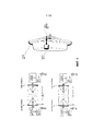
Наиболее близким аналогом к предложенной в настоящей заявке системе и способу радиорелейной связи с электронной подстройкой луча является система, раскрытая в патенте США №6,587,699 "Narrow beamwidth communication link with alignment camera". Данный патент описывает систему связи типа точка-точка, включающую 2 удаленных друг от друга высокоскоростных приемопередатчика с высоконаправленными антеннами, на каждом из которых установлены телескопические камеры, а также процессор для обработки получаемого камерами изображения (фиг. 1). Указанная система обеспечивает не только точную настройку антенн друг на друга, но и автоматическую подстройку лучей при смещениях и отклонениях несущей конструкции. Принцип действия системы подстройки лучей заключается в получении некоторых опорных изображений с камер, при которых обеспечивается наилучшее качество передачи сигнала. При отклонении луча изображение, получаемое с камеры, также изменяется. Таким образом, отклонение луча можно отследить и скорректировать по изменению изображения по сравнению с опорным. Также в указанном изобретении раскрыт способ подстройки луча с помощью описанной системы.The closest analogue to the system and method for radio relay communication with electronic beam adjustment proposed in this application is the system disclosed in US Pat. No. 6,587,699, "Narrow beamwidth communication link with alignment camera". This patent describes a point-to-point communication system, including 2 remote-controlled high-speed transceivers with highly directional antennas, each of which has telescopic cameras, as well as a processor for processing the image received by the cameras (Fig. 1). The specified system provides not only precise tuning of the antennas to each other, but also automatic adjustment of the rays with displacements and deviations of the supporting structure. The principle of the beam adjustment system is to obtain some reference images from cameras, which ensure the best quality of signal transmission. When the beam is deflected, the image received from the camera also changes. Thus, the deviation of the beam can be tracked and corrected for changes in the image compared to the reference. Also in the specified invention disclosed a method of adjusting the beam using the described system.
Однако для системы, раскрытой в патенте США №6,587,699, требуется использование дополнительного дорогостоящего оборудование, интегрированного в структуру РРС, а также вовлечение специального квалифицированного персонала при начальной юстировке антенн, что также увеличивает расходы.However, the system disclosed in US Pat. No. 6,587,699 requires the use of additional expensive equipment integrated into the PPC structure, as well as the involvement of specialized qualified personnel in the initial alignment of the antennas, which also increases costs.
Таким образом, анализ рассмотренных систем, известных из уровня техники, показывает, что существует необходимость в обеспечении полностью электронной точной подстройки направления луча и слежения за этим направлением в дальнейшем. Это значительно ускорит процессы установления радиосоединения и его восстановления, а также избавит от необходимости выполнения работ на месте установки РРС квалифицированным персоналом.Thus, the analysis of the considered systems known from the prior art shows that there is a need to provide fully electronic accurate adjustment of the beam direction and tracking this direction in the future. This will significantly speed up the processes of establishing a radio connection and its restoration, as well as eliminate the need for qualified personnel to perform work at the RRS installation site.
Сущность изобретенияSUMMARY OF THE INVENTION
Задачей изобретения является преодоление или устранение как минимум одного из недостатков вышерассмотренных систем.The objective of the invention is to overcome or eliminate at least one of the disadvantages of the above systems.
Другой задачей изобретения является обеспечение в системе радиорелейной связи возможности полностью электронной подстройки направлений луча для поддержки высокой скорости передачи данных с встроенной коррекцией и восстановлением соединения при необходимости.Another objective of the invention is the provision in the radio relay communication system of the possibility of fully electronic adjustment of the beam directions to support high data rates with built-in correction and reconnection if necessary.
Указанные задачи решены за счет применения электронного сканирования для настройки направлений антенн, что позволяет исключить необходимость использования дорогостоящего оборудования в радиорелейной станции (например, камер, детекторов мощности, и т.п.), а также и устройств для точной механической юстировки (моторов). Дополнительно электронное сканирование луча обеспечивает намного более простую процедуру начального позиционирования антенн и автоматического слежения и подстройки направлений лучей антенн без длительного разрыва соединения.These tasks are solved by using electronic scanning to adjust the directions of the antennas, which eliminates the need for expensive equipment in a radio relay station (for example, cameras, power detectors, etc.), as well as devices for precise mechanical alignment (motors). In addition, electronic beam scanning provides a much simpler procedure for initial positioning of antennas and automatic tracking and adjusting the directions of the antenna beams without a long connection break.
Соответственно изобретение раскрывает радиорелейную станцию с антеннами с электронным сканированием, выполненную с возможностью автоматической подстройки направлений антенн.Accordingly, the invention discloses a radio relay station with antennas with electronic scanning, configured to automatically adjust the directions of the antennas.
Более того, в соответствии с изобретением использование антенн с электронной подстройкой луча в некотором диапазоне углов позволяет значительно облегчить точную взаимную настройку антенн двух радиорелейных станций.Moreover, in accordance with the invention, the use of antennas with electronic beam adjustment in a certain range of angles can significantly facilitate the accurate mutual tuning of the antennas of two radio relay stations.
Необходимо также отметить, что несмотря на то, что в изобретении раскрыты система и способ радиорелейного соединения с электронной подстройкой направлений лучей, начальное позиционирование и автоматическая подстройка направлений луча при необходимости могут быть выполнены любым известным из уровня техники способом.It should also be noted that despite the fact that the invention discloses a system and method of radio relay connection with electronic adjustment of the directions of the rays, the initial positioning and automatic adjustment of the directions of the beam, if necessary, can be performed by any method known from the prior art.
В соответствии с изобретением начальная юстировка антенн и последующее автоматическое слежение и подстройка направлений луча осуществляется за счет введения в состав РРС модуля управления, выполняющего алгоритмы контроля и изменения диаграммы направленности антенны на основе информации, получаемой от РРС. Указанный модуль управления выполняет также генерацию управляющих сигналов для антенны на основе полученных параметров производительности системы связи. Реализация модуля управления и интегрирование его в состав РРС является понятной для специалиста в области техники из технического описания, представленного в настоящей заявке. Модуль управления содержит блок мониторинга, выполненный с возможностью измерения параметров производительности системы связи.In accordance with the invention, the initial alignment of the antennas and the subsequent automatic tracking and adjustment of the beam directions is carried out by introducing into the PPC a control module that performs algorithms for monitoring and changing the antenna pattern based on the information received from the PPC. The specified control module also generates control signals for the antenna based on the received communication system performance parameters. The implementation of the control module and its integration into the RRS is understandable for a specialist in the field of technology from the technical description presented in this application. The control module comprises a monitoring unit configured to measure communication system performance parameters.
Таким образом, в одном примере реализации разработанного нового технического решения радиорелейная система содержит два разнесенных в пространстве приемопередатчика (станции) миллиметрового диапазона длин волн, которые обеспечивают прием и передачу данных с высокой пропускной способностью в режиме частотного дуплексирования. Каждый приемопередатчик содержит антенну с высоким коэффициентом усиления, способную осуществлять электронное сканирование в некотором непрерывном угловом пространстве.Thus, in one example of the implementation of the developed new technical solution, the radio-relay system contains two spaced apart transceivers (stations) of the millimeter wavelength range, which provide reception and transmission of data with high throughput in frequency duplexing mode. Each transceiver comprises a high gain antenna capable of electronically scanning in some continuous angular space.
Контроль антенны осуществляется модулем управления с использованием контрольных алгоритмов с целью подстройки направления основного луча диаграммы направленности. Каждый модуль управления дополнительно выполнен с возможностью генерирования инструкций по выбору оптимального направления луча антенны на противоположной стороне системы связи, а каждый приемопередатчик выполнен с возможностью передачи инструкций по выбору оптимального направления луча антенны на противоположной стороне системы связи.Antenna control is carried out by the control module using control algorithms in order to adjust the direction of the main beam. Each control module is further configured to generate instructions for selecting the optimal direction of the antenna beam on the opposite side of the communication system, and each transceiver is configured to transmit instructions for choosing the optimal direction of the antenna beam on the opposite side of the communication system.
Различные варианты реализации предложенных системы и способа для подстройки луча антенны, адаптированные для конкретных типов антенн и радиорелейных систем, также рассматриваются в рамках настоящего описания.Various embodiments of the proposed system and method for adjusting the antenna beam, adapted for specific types of antennas and microwave systems, are also considered in the framework of the present description.
Еще один аспект изобретения относится к способу точной начальной настройки направлений лучей и последующего слежения и подстройки направлений лучей при возникновении необходимости.Another aspect of the invention relates to a method for fine-tuning the initial directions of the rays and then tracking and adjusting the directions of the rays when necessary.
Соответственно в одном из вариантов реализации изобретения представлена миллиметровая система радиосвязи типа точка-точка с электронной подстройкой антенн, которая содержит первый приемопередатчик, установленный в первом месте расположения, и второй приемопередатчик, установленный во втором месте расположении, причем первый приемопередатчик выполнен с возможностью передачи и приема данных от второго приемопередатчика, а второй приемопередатчик выполнен с возможностью передачи и приема данных от первого приемопередатчика. Каждый приемопередатчик содержит антенну с узким основным лучом диаграммы направленности, способную переключать направление основного луча электронным образом между по меньшей мере двумя направлениями, и модуль управления, который управляет диаграммой направленности антенны на основе контрольной информации, получаемой от приемопередатчика, и генерирует выходные управляющие сигналы для антенны.Accordingly, in one embodiment of the invention, there is provided a point-to-point millimeter-wave radio communication system with electronic antenna tuning, which comprises a first transceiver installed in a first location and a second transceiver installed in a second location, the first transceiver being configured to transmit and receive data from the second transceiver, and the second transceiver is configured to transmit and receive data from the first transceiver. Each transceiver comprises an antenna with a narrow main beam of the radiation pattern, capable of switching the main beam direction electronically between at least two directions, and a control module that controls the antenna radiation pattern based on the control information received from the transceiver and generates output control signals for the antenna .
Рассмотренная выше двунаправленная система передачи данных в соответствии с одним из вариантов реализации изобретения обеспечивает радиосоединение с большой пропускной способностью и автоматической подстройкой направлений лучей, когда это необходимо в процессе передачи данных с помощью антенн с электронным сканированием, управляемых модулем управления, анализирующим контрольную информацию. Также новое использование таких антенн с электронным сканированием и модуля управления в радиорелейной системе позволяет осуществлять полностью автономную подстройку антенн без необходимости привлечения квалифицированного персонала.The above-described bi-directional data transmission system in accordance with one embodiment of the invention provides a high-bandwidth radio connection and automatic adjustment of the beam directions when necessary in the process of data transmission using electronic scanning antennas controlled by a control module that analyzes control information. Also, the new use of such antennas with electronic scanning and the control module in the radio relay system allows for fully autonomous tuning of the antennas without the need for qualified personnel.
Согласно одному из вариантов реализации блоки мониторинга параметров производительности системы связи реализованы в виде блоков цифрового модема.According to one embodiment, the blocks for monitoring the performance parameters of a communication system are implemented as blocks of a digital modem.
Предпочтительно указанная система используется для организации транспортных каналов сотовых систем связи и указанные антенны имеют коэффициент усиления более 30 дБи.Preferably, said system is used to organize transport channels of cellular communication systems, and said antennas have a gain of more than 30 dBi.
В соответствии с другим вариантом реализации изобретения каждый приемопередатчик работает в режиме частотного дуплексирования для разделения принимаемых и передаваемых сигналов. Это обеспечивает увеличение скорости передачи данных и уменьшение ошибок при передаче информации.In accordance with another embodiment of the invention, each transceiver operates in frequency duplexing mode to separate received and transmitted signals. This provides an increase in data transfer rate and reduction of errors in the transmission of information.
Предпочтительно первый приемопередатчик передает сигналы в полосе частот 71-76 ГГц и принимает сигналы в полосе 81-86 ГГц, а второй приемопередатчик, наоборот, передает сигналы в полосе 81-86 ГГц и принимает сигналы в полосе 71-76 ГГц. Таким образом, в соответствии с изобретением могут быть использованы наиболее перспективные полосы частот для передачи данных, которые выделены в различных странах мира для радиорелейных систем связи.Preferably, the first transceiver transmits signals in the frequency band 71-76 GHz and receives signals in the band 81-86 GHz, and the second transceiver transmits signals in the band 81-86 GHz and receives signals in the band 71-76 GHz. Thus, in accordance with the invention, the most promising frequency bands for data transmission, which are allocated in various countries of the world for radio relay communication systems, can be used.
В соответствии с еще одним вариантом реализации изобретения угловое расстояние между двумя соседними направлениями луча равно или меньше, чем ширина луча антенны по уровню половинной мощности. Такая конфигурация позволяет выполнять точную настройку приемопередатчиков при сканировании в непрерывной угловой области.According to another embodiment of the invention, the angular distance between two adjacent beam directions is equal to or less than the beam width of the antenna at half power. This configuration allows you to fine tune the transceivers when scanning in a continuous corner region.
В соответствии с еще одним вариантом реализации по меньшей мере одна из антенн является параболической антенной с решеткой переключаемых облучателей, расположенных в фокальной плоскости основного зеркала и необходимых для электронного управления лучом, или антенной Кассегрена с решеткой переключаемых облучателей, расположенных в фокальной плоскости, или линзовой антенной с фокальной решеткой переключаемых облучателей, или интегрированной линзовой антенной с фокальной решеткой переключаемых облучателей для электронного управления лучом.According to yet another embodiment, at least one of the antennas is a parabolic antenna with an array of switched irradiators located in the focal plane of the main mirror and necessary for electron beam control, or a Cassegrain antenna with an array of switched irradiators located in the focal plane, or a lens antenna with focal array of switched irradiators, or integrated lens antenna with focal array of switched irradiators for electronic control beam.
В соответствии с еще одним вариантом реализации изобретения модуль управления каждого из приемопередатчиков содержит блок начальной юстировки антенны, выполненный с возможностью осуществления начальной юстировки антенны первого приемопередатчика и антенны второго приемопередатчика в направлении друг друга, блок мониторинга для генерации сигнала для инициации подстройки и блок подстройки, выполненный с возможностью подстройки антенны первого приемопередатчика и/или антенны второго приемопередатчика в соответствии с сигналами от блока мониторинга. Такое устройство модуля управления обеспечивает качественную и быструю начальную настройку антенн приемопередатчиков и дальнейшую подстройку по меньшей мере одного приемопередатчика системы когда это необходимо.According to another embodiment of the invention, the control module of each of the transceivers comprises an initial antenna alignment unit configured to perform initial alignment of the antenna of the first transceiver and the antenna of the second transceiver in the direction of each other, a monitoring unit for generating a signal for initiating adjustment, and an adjustment unit with the ability to adjust the antenna of the first transceiver and / or antenna of the second transceiver in accordance with the signals from monitoring unit. Such a control module device provides high-quality and quick initial tuning of the transceiver antennas and further tuning of at least one system transceiver when necessary.
В соответствии с еще одним вариантом реализации изобретения указанный модуль управления каждого приемопередатчика выполнен в виде программируемого микроконтроллера.In accordance with another embodiment of the invention, said control module of each transceiver is designed as a programmable microcontroller.
В соответствии с еще одним вариантом реализации изобретения логическая схема модуля управления реализована в блоке цифрового модема каждого приемопередатчика.In accordance with another embodiment of the invention, the control module logic is implemented in a digital modem unit of each transceiver.
Также разработан способ для взаимной настройки антенн первого и второго приемопередатчика радиорелейной системы типа точка-точка миллиметрового диапазона длин волн с антеннами с электронным сканированием луча. Такой способ в наиболее общей реализации содержит следующие этапы: А) передача антенной первого приемопередатчика сигнала по меньшей мере в одном из возможных направлений луча; Б) прием сигнала антенной второго приемопередатчика по меньшей мере с одного из возможных направлений луча, причем в это время положение луча антенны первого приемопередатчика остается неизменным; В) определение такой комбинации направлений лучей антенн двух приемопередатчиков, которые позволяют обеспечить предварительно заданный критерий, причем каждый модуль управления генерирует инструкции по выбору оптимального направления луча антенны на противоположной стороне системы связи, а каждый приемопередатчик передает инструкции по выбору оптимального направления луча антенны на противоположной стороне системы; и затем Г) применение найденных положений лучей антенн на одном или двух приемопередатчиках.A method has also been developed for the mutual tuning of the antennas of the first and second transceiver of a point-to-point millimeter-wave radio-relay system with antennas with electron beam scanning. Such a method in the most general implementation comprises the following steps: A) transmitting by the antenna the first transceiver of the signal in at least one of the possible beam directions; B) receiving the signal of the antenna of the second transceiver from at least one of the possible directions of the beam, and at this time the position of the beam of the antenna of the first transceiver remains unchanged; C) the definition of such a combination of the directions of the antenna beams of two transceivers that allow you to provide a predetermined criterion, and each control module generates instructions for choosing the optimal direction of the antenna beam on the opposite side of the communication system, and each transceiver transmits instructions for choosing the optimal direction of the antenna beam on the opposite side systems; and then D) application of the found positions of the antenna beams on one or two transceivers.
Раскрытый способ обеспечивает точную настройку направлений лучей антенн, которые могут быть в автоматическом режиме восстановлены, используя любой соответствующий критерий при наступлении любого события, связанного с изменением ориентации антенн.The disclosed method provides precise adjustment of the directions of the antenna beams, which can be automatically restored using any appropriate criterion upon the occurrence of any event associated with a change in the orientation of the antennas.
В предпочтительном варианте реализации раскрытого способа тестируются все возможные комбинации направлений лучей двух приемопередатчиков. Это обеспечивает более точную настройку, что сводит к минимуму возможные ошибки при передаче данных.In a preferred embodiment of the disclosed method, all possible combinations of the beam directions of two transceivers are tested. This provides a more accurate setting, which minimizes possible errors in data transfer.
В одном из вариантов реализации способа по изобретению тестируются только соседние положения луча к некоторому направлению, на которое была настроена антенна приемопередатчика до начала процедуры подстройки луча.In one embodiment of the method according to the invention, only adjacent beam positions are tested to a certain direction in which the transceiver antenna was tuned before the beam adjustment procedure was started.
В соответствии с другим вариантом реализации изобретения первым приемопередатчиком передается по меньшей мере одна тестовая последовательность, известная на стороне второго приемопередатчика. Эта тестовая последовательность принимается вторым приемопередатчиком и служит для определения комбинации наиболее эффективных направлений лучей двух антенн, при которой достигается некоторый заранее заданный критерий.In accordance with another embodiment of the invention, at least one test sequence known on the side of the second transceiver is transmitted by the first transceiver. This test sequence is received by the second transceiver and is used to determine the combination of the most effective beam directions of the two antennas, at which some predetermined criterion is achieved.
Согласно еще одному варианту реализации по меньшей мере одна тестовая последовательность передается первым приемопередатчиком, причем различные тестовые последовательности передаются антенной в различных направлениях, и второй приемопередатчик способен таким образом определить наиболее эффективное направление луча первого приемопередатчика на основе типа тестовой последовательности, принятой наилучшим образом.According to another embodiment, at least one test sequence is transmitted by the first transceiver, wherein different test sequences are transmitted by the antenna in different directions, and the second transceiver is thus able to determine the most efficient beam direction of the first transceiver based on the type of test sequence that is best received.
В соответствии с еще одним вариантом реализации изобретения второй приемопередатчик информирует первый приемопередатчик о направлении луча антенны для последнего, которое позволяет обеспечить необходимый критерий. Такое информирование производится путем передачи индекса, ассоциированного с тестовой последовательностью, переданной в данном направлении. При этом информация об индексе луча встраивается в поток данных, передаваемых от второго приемопередатчика к первому приемопередатчику.In accordance with another embodiment of the invention, the second transceiver informs the first transceiver of the direction of the antenna beam for the latter, which allows you to provide the necessary criterion. Such information is produced by transmitting the index associated with the test sequence transmitted in this direction. In this case, information about the beam index is embedded in the data stream transmitted from the second transceiver to the first transceiver.
В соответствии с еще одним вариантом реализации изобретения сигналы, используемые для передачи данных от первого ко второму приемопередатчику, также используются и для измерения принимаемой мощности на стороне второго приемопередатчика. Это позволяет определить комбинацию направлений лучей антенн двух приемопередатчиков так, чтобы удовлетворялся необходимый критерий.According to another embodiment of the invention, the signals used to transmit data from the first to the second transceiver are also used to measure received power on the side of the second transceiver. This allows you to determine the combination of the directions of the rays of the antennas of the two transceivers so that the necessary criterion is satisfied.
Предпочтительно требуемый критерий состоит в максимизации принимаемой мощности на стороне второго приемопередатчика. Это обеспечивает наилучшее качество передачи данных и минимальную вероятность ошибок, возникающих в системе при передаче данных.Preferably, the desired criterion is to maximize the received power on the side of the second transceiver. This ensures the best quality of data transfer and the minimum probability of errors that occur in the system during data transfer.
В соответствии с еще одним вариантом реализации изобретения требуемый критерий заключается в максимизации скорости передачи данных от первого приемопередатчика ко второму приемопередатчику.In accordance with yet another embodiment of the invention, the required criterion is to maximize the data rate from the first transceiver to the second transceiver.
В соответствии с еще одним вариантом реализации изобретения требуемый критерий заключается в обеспечении надежной передачи данных между первым и вторым приемопередатчиками.In accordance with another embodiment of the invention, the required criterion is to ensure reliable data transmission between the first and second transceivers.
В соответствии с еще одним вариантом реализации изобретения предложенный способ дополнительно содержит этап непрерывного мониторинга уровня принимаемой мощности и периодического выполнения этапов А) - Г) в случае разрыва радиосоединения и прекращения обмена данными между первым и вторым приемопередатчиками.In accordance with another embodiment of the invention, the proposed method further comprises the step of continuously monitoring the level of received power and periodically performing steps A) to D) in the event of a disconnected radio connection and termination of data exchange between the first and second transceivers.
Согласно еще одному варианту реализации способ предполагает дополнительное выполнение этапов А) - Г) каждый раз после передачи одного или более пакетов данных.According to another embodiment, the method involves additionally performing steps A) to D) each time after the transmission of one or more data packets.
Согласно еще одному варианту реализации способ предполагает дополнительное выполнение этапов А) - Г) с регулярной периодичностью после истечения некоторого предустановленного временного интервала.According to yet another embodiment, the method involves the additional execution of steps A) to D) with regular periodicity after a predetermined time interval has elapsed.
В соответствии с еще одним вариантом реализации изобретения второй приемопередатчик выполнен с возможностью определения успешной передачи данных от первого приемопередатчика, а раскрытый способ включает выполнение этапов А) - Г) в случае или последовательного приема одного или более ошибочных пакетов данных или потери синхронизации между первым и вторым приемопередатчиками.In accordance with yet another embodiment of the invention, the second transceiver is configured to determine successful data transmission from the first transceiver, and the disclosed method includes performing steps A) to D) in the case of either receiving one or more erroneous data packets sequentially or losing synchronization between the first and second transceivers.
Согласно еще одному варианту реализации второй приемопередатчик выполнен с возможностью определения уровня принимаемой мощности, а предлагаемый способ включает выполнение этапов А) - Г) в случае уменьшения уровня принимаемой вторым приемопередатчиком мощности ниже некоторого заранее определенного порогового значения.According to another embodiment, the second transceiver is configured to determine the level of received power, and the proposed method includes performing steps A) to D) in the event that the level of power received by the second transceiver decreases below a certain predetermined threshold value.
Предпочтительно измеренная принимаемая мощность вначале усредняется в течение 10 мин или более, и затем усредненное значение сравнивается с установленным порогом.Preferably, the measured received power is first averaged for 10 minutes or more, and then the averaged value is compared with a set threshold.
Другие аспекты и особенности реализации изобретения могут быть более детально поняты из приложенных чертежей и подробного описания.Other aspects and features of the invention may be more fully understood from the attached drawings and detailed description.
Краткое описание чертежейBrief Description of the Drawings
На фиг. 1 проиллюстрирована подстройка направлений лучей антенны Кассегрейна в радиорелейной системе, известной из уровня техники.In FIG. 1 illustrates the adjustment of the directions of the rays of the Cassegrain antenna in a radio relay system known in the art.
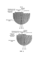
На фиг. 2 показана структура интегрированной линзовой антенны с электронным управлением лучом.In FIG. 2 shows the structure of an integrated electron beam control lens antenna.
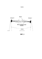
На фиг. 3 схематически показана радиорелейная система с антеннами с электронным сканированием.In FIG. 3 schematically shows a radio-relay system with antennas with electronic scanning.
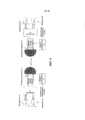
На фиг. 4 проиллюстрирована структура радиорелейной системы, работающей в полнодуплексном режиме с частотным разделением приема и передачи, с интегрированными линзовыми антеннами с управляемым лучом.In FIG. 4 illustrates the structure of a full-duplex radio-relay system with frequency division of reception and transmission, with integrated lens antennas with a controlled beam.
На фиг. 5 показана блок-схема способа настройки направлений лучей для антенн радиорелейной системы в соответствии с изобретением.In FIG. 5 shows a flowchart of a method for adjusting beam directions for antennas of a radio relay system in accordance with the invention.
Детальное описание изобретенияDETAILED DESCRIPTION OF THE INVENTION
В соответствии с одним из вариантов реализации раскрываемого изобретения на каждом приемопередатчике РРС используются высоконаправленные антенны с возможностью электронного переключения направления луча в некотором непрерывном диапазоне углов, превышающем ширину луча антенны. При этом такое электронное сканирование может быть обеспечено в различных антеннах, как то зеркальные антенны, линзовые антенны с вынесенным облучателем, интегрированные линзовые антенны и другие. Такие антенны должны быть разработаны так, чтобы обеспечивать переключение между первичными облучателями в решетке, расположенной в фокальной плоскости основного зеркала или линзы, что тем самым формирует луч диаграммы направленности в различных направлениях.In accordance with one embodiment of the disclosed invention, high-directional antennas are used on each PPC transceiver with the possibility of electronically switching the beam direction in a certain continuous range of angles exceeding the antenna beam width. Moreover, such electronic scanning can be provided in various antennas, such as mirror antennas, lens antennas with remote irradiator, integrated lens antennas and others. Such antennas should be designed to allow switching between the primary irradiators in a grating located in the focal plane of the main mirror or lens, thereby forming a beam in different directions.
Наиболее перспективным является применение в предложенной системе РРС сканирующих интегрированных линзовых антенн, представляющих собой диэлектрическую линзу эллиптической или квазиэллиптической формы с интегрированной на ее заднюю (плоскую) фокальную поверхность решеткой переключаемых первичных облучателей. Примеры структур интегрированной линзовой антенны показаны на фиг. 2. Такая конфигурация антенны наиболее совместима с массовыми технологиями реализации пленарных облучателей на печатных платах и технологиями полупроводниковых микросхем, которые используются для создания приемопередатчиков и переключающих схем вплоть до миллиметрового диапазона длин волн. Это обеспечивает минимальную стоимость и максимальную эффективность РРС при массовом производстве.The most promising is the use of scanning integrated lens antennas in the proposed RRS system, which are an elliptical or quasi-elliptic dielectric lens with an array of switched primary irradiators integrated on its rear (flat) focal surface. Examples of structures of an integrated lens antenna are shown in FIG. 2. Such an antenna configuration is most compatible with mass technologies for the implementation of plenary irradiators on printed circuit boards and semiconductor chip technologies that are used to create transceivers and switching circuits up to the millimeter wavelength range. This ensures minimum cost and maximum efficiency of PPC in mass production.
Основной принцип выбора направлений лучей антенн двух РРС проиллюстрирован на фиг. 3. На данном чертеже схематически показаны две антенны 1, установленные на вышках 4 сотовых сетей связи, и набор возможных пересекающихся по некоторому заданному уровню лучей 2. Также красными линиями показаны лучи 3, которые выбираются по некоторому критерию для обеспечения наиболее эффективных приема и передачи сигнала. В одном из вариантов реализации угловое расстояние между соседними направлениями лучей в каждой антенне равны или меньше, чем ширина луча антенны по уровню половинной мощности.The basic principle of selecting the beam directions of the antennas of two PPCs is illustrated in FIG. 3. This drawing schematically shows two
Предлагаемая система РРС в наиболее предпочтительном варианте реализации обеспечивает полнодуплексную связь с частотным разнесением приема и передачи в перспективных диапазонах частот 71-76 ГГц и 81-86 ГГц, для которых во многих странах мира упразднена или установлена упрощенная процедура лицензирования. Структура предлагаемой системы РРС, работающей в режиме частотного дуплексирования, со сканирующими интегрированными линзовыми антеннами показана на фиг. 4. Основными функциональными блоками каждой радиорелейной станции в рассматриваемой системе являются линзовая антенна 10, решетка переключаемых облучателей 11, интегрированных на линзу, переключающая схема 12, модуль 13 управления, диплексер 14, передатчик 15 и приемник 16. Одна станция передает сигнал в полосе частот 71-76 ГГц, а принимает в полосе 81-86 ГГц, тогда как другая передает сигнал в полосе частот 81-86 ГГц, а принимает в полосе 71-76 ГГц. В данном случае диплексер 14 предназначен для обеспечения изоляции между приемником и передатчиком в каждой РРС. Необходимо отметить, что антенна 10 может быть представлена и другими типами сканирующих антенн, например параболической антенной, антенной Кассегрена или классической линзовой антенной с решеткой переключаемых облучателей, расположенной в фокальной плоскости фокусирующего элемента.The proposed RRS system in the most preferred embodiment provides full-duplex communication with frequency diversity of reception and transmission in the prospective frequency ranges 71-76 GHz and 81-86 GHz, for which a simplified licensing procedure has been eliminated or established in many countries of the world. The structure of the proposed RRS system operating in the frequency duplex mode with scanning integrated lens antennas is shown in FIG. 4. The main functional blocks of each radio relay station in the system under consideration are the lens antenna 10, the array of switchable irradiators 11 integrated into the lens, the switching circuit 12, the
В рассмотренном варианте реализации системы РРС модули 13 управления выполняют алгоритмы для управления основным лучом диаграммы направленности антенны. Причем для выполнения алгоритмов модули управления используют контрольную информацию от блока цифрового модема РРС (например, уровень мощности сигнала или максимальную скорость передачи данных по радиосоединению) и/или сетевого устройства, расположенного в сетевой топологии после РРС и выполненного с возможностью измерения скорости передачи данных и других показателей эффективности радиосоединения. На выходе модуль управления генерирует управляющие сигналы, определяющие выбор соответствующего положения луча антенны РРС. Также модуль управления одной РРС может генерировать инструкции для нахождения оптимального направления луча антенны на ответной РРС радиосоединения. Для такого сигнализирования может передаваться, например, индекс оптимального направления луча антенны на ответную сторону. Для этого модуль управления может иметь подключение к блоку цифрового модема РРС (если последний поддерживает возможность передачи индекса) или к сетевому устройству.In the considered embodiment of the PPC system, the
Дополнительно модуль управления может иметь сетевое подключение для удаленного управления и слежения за характеристиками производительности РРС.Additionally, the control module may have a network connection for remote control and monitoring the performance characteristics of the PPC.
С точки зрения аппаратной реализации, требуемый модуль управления может быть создан с использованием различных аппаратных платформ. Так как вычислительные затраты на реализацию алгоритмов электронного сканирования лучом не являются высокими, то наиболее предпочтительным вариантом является использование какого-либо программируемого микроконтроллера. Модуль управления при этом может иметь блоки для выполнения операций начальной юстировки антенн, слежения за заранее определенными параметрами РРС и подстройки антенн при необходимости. В другом варианте логическая схема модуля управления может быть реализована в блоке цифрового модема каждой РРС без использования дополнительных электронных компонентов.From the point of view of hardware implementation, the required control module can be created using various hardware platforms. Since the computational cost of implementing electron beam scanning algorithms is not high, the most preferred option is to use some kind of programmable microcontroller. The control module may have blocks for performing the initial alignment of the antennas, tracking the predefined parameters of the RRS and adjusting the antennas if necessary. In another embodiment, the logic circuit of the control module can be implemented in the digital modem unit of each PPC without the use of additional electronic components.
Рассматриваемая система радиорелейной связи с электронной подстройкой луча позволяет значительно упростить и ускорить процедуру первичной юстировки антенн приемопередатчиков РРС, а также обеспечивает автоматическое восстановление соединения при небольших изменениях ориентации РРС вследствие воздействия различных внешних факторов (ветер, вибрации, различная интенсивность нагревания несущих конструкций в различное время суток и другие причины). С другой стороны, система РРС с электронной подстройкой луча позволяет устанавливать приемопередатчики в наиболее эффективных для передачи местах (вершины вышек, башен, высотных зданий), невзирая на более значительные и частые отклонения несущих конструкций.The considered radio relay communication system with electronic beam adjustment makes it possible to significantly simplify and speed up the initial alignment of the RRS transceiver antennas, and also provides automatic reconnection with small changes in the RRS orientation due to various external factors (wind, vibration, different heating intensities of the load-bearing structures at different times of the day and other reasons). On the other hand, the RRS system with electronic beam adjustment allows you to install transceivers in the most efficient places for transmission (the tops of towers, towers, high-rise buildings), despite the more significant and frequent deviations of the supporting structures.
В некоторых вариантах реализации представленная радиорелейная система содержит антенны с коэффициентом усиления более 30 дБи и может быть использована без ограничений для построения транспортных каналов сотовых систем связи, систем передачи данных типа точка-точка и других систем радиосвязи миллиметрового диапазона длин волн.In some embodiments, the presented radio-relay system contains antennas with a gain of more than 30 dBi and can be used without limitation for constructing transport channels of cellular communication systems, point-to-point data transmission systems, and other millimeter-wave radio communication systems.
Для того чтобы реализовать рассмотренное выше преимущество, заключающееся в возможности автоматической компенсации отклонения ориентаций лучей, система РРС должна также реализовывать способ выполнения процедуры формирования луча и выбора оптимальной комбинации направлений антенн двух радиорелейных станций. Возможность электронной подстройки луча позволяет применить различные способы такой подстройки, которые также раскрываются в изобретении.In order to realize the above advantage, which consists in the possibility of automatically compensating for deviations in the orientations of the beams, the PPC system must also implement a method for performing the beam formation procedure and choosing the optimal combination of antenna directions of two radio relay stations. The possibility of electron beam adjustment allows you to apply various methods of such adjustment, which are also disclosed in the invention.
Критерии для оптимизации (выбора) направлений лучей могут быть различными. Наиболее обоснованный критерий это уровень принимаемой радиорелейной станцией мощности. Однако уровень мощности принимаемого сигнала может быть не всегда оценен для использования в алгоритме управления антенны. Например, такая ситуация может возникнуть в случае, когда линзовая антенна используется как внешняя антенна к РРС (и может использоваться попеременно с фиксированной неуправляемой антенной) и когда алгоритм управления не имеет доступа к внутренним параметрам РРС, таким как уровень принимаемой мощности сигнала. В таких случаях вместо уровня мощности принимаемого сигнала могут использоваться другие критерии, например скорость передачи данных, обеспечиваемая радиорелейной линией или возможность передачи данных через линию (т.е. критерием может являться существование или обрыв радиосоединения).The criteria for optimizing (choosing) the directions of the rays can be different. The most reasonable criterion is the level of power received by the radio relay station. However, the power level of the received signal may not always be estimated for use in the antenna control algorithm. For example, this situation may occur when the lens antenna is used as an external antenna to the RRS (and can be used interchangeably with a fixed uncontrolled antenna) and when the control algorithm does not have access to the internal parameters of the RRS, such as the level of received signal power. In such cases, instead of the power level of the received signal, other criteria can be used, for example, the data rate provided by the radio link or the ability to transmit data through the line (i.e., the criterion may be the existence or interruption of the radio connection).
Поиск оптимальной комбинации направлений лучей антенн должен выполняться посредством тестирования уровня мощности принимаемого сигнала (или другой целевой характеристики как рассмотрено выше) и выбора той комбинации, которая соответствует максимуму целевой характеристики. Одним из подходов к такому поиску может быть выполнение исчерпывающего поиска по всем возможным комбинациям направлений лучей двух антенн. В другом варианте реализации тестирование выполняется только для соседних направлений лучей к тем, которые были использованы системой РРС для передачи данных до начала процесса поиска новой комбинации. Общая блок-схема предлагаемого способа настройки направлений лучей антенн РРС представлена на фиг. 5.The search for the optimal combination of the directions of the antenna rays should be performed by testing the power level of the received signal (or another target characteristic as discussed above) and choosing the combination that corresponds to the maximum of the target characteristic. One approach to such a search may be to perform an exhaustive search on all possible combinations of the directions of the rays of two antennas. In another embodiment, testing is performed only for adjacent ray directions to those that were used by the PPC system to transmit data prior to the process of searching for a new combination. The general block diagram of the proposed method for adjusting the beam directions of the RRS antennas is shown in FIG. 5.
Представленный на фиг. 5 способ взаимной настройки направлений лучей антенн двух РРС, включает следующие этапы: А) передача первой РРС сигнала по некоторым направлениям основного луча антенны; Б) при неизменном направлении основного луча антенны первой РРС прием сигнала второй РРС с некоторых направлений основного луча антенны; В) выбор комбинации направлений основных лучей антенн обеих РРС, соответствующей максимуму заданного критерия (например, максимуму принимаемой мощности на второй РРС), и затем Г) применение выбранных направлений основных лучей антенн к одной или двум радиорелейным станциям. Все указанные этапы в рассмотренном способе могут выполняться всякий раз после передачи одного или более пакетов данных или после истечения некоторого заранее определенного временного интервала.Presented in FIG. 5, a method for mutually adjusting the directions of the antenna beams of two RRSs, includes the following steps: A) transmitting the first RRS signal in some directions of the main antenna beam; B) with the direction of the main beam of the antenna of the first RRS unchanged, receiving the signal of the second RRS from some directions of the main beam of the antenna; B) selecting a combination of the directions of the main rays of the antennas of both RRSs corresponding to the maximum of the given criterion (for example, the maximum of the received power at the second RRS), and then D) applying the selected directions of the main rays of the antennas to one or two radio relay stations. All these steps in the considered method can be performed each time after the transmission of one or more data packets or after a certain predetermined time interval has elapsed.
Для выполнения процедуры поиска направлений и формирования лучей за счет измерения уровня принимаемой мощности одна из РРС в системе может посылать специальные тестовые сигналы, известные на второй РРС, и, таким образом, облегчить измерение уровня принимаемой мощности второй станцией и обеспечить более точные и быстрые результаты измерений. Это облегчает также и определение комбинации направлений основных лучей антенн двух РРС, при которых обеспечивается выполнение некоторого критерия. Например, критерий может состоять в максимизации принимаемой второй РРС мощности, максимизации скорости передачи данных между первой и второй РРС. Тестовые сигналы могут быть различными для различных направлений лучей антенны передатчика, что обеспечит определение текущего направления передачи на приемной станции для последующей передачи индекса этого направления луча обратно на передающую станцию. Такая обратная связь может осуществляться в том же канале связи, который использовался для передачи данных, за счет встраивания этой информации в поток данных.To carry out the procedure of searching for directions and generating rays by measuring the level of received power, one of the RRS in the system can send special test signals known to the second RRS, and thus facilitate the measurement of the level of received power by the second station and provide more accurate and faster measurement results . This also facilitates the determination of the combination of the directions of the main rays of the antennas of two RRSs, at which some criterion is satisfied. For example, a criterion may consist in maximizing the received second PPC power, maximizing the data rate between the first and second PPC. Test signals can be different for different directions of the transmitter antenna beams, which will determine the current transmission direction at the receiving station for subsequent transmission of the index of this beam direction back to the transmitting station. Such feedback can be carried out in the same communication channel that was used for data transmission, by embedding this information in the data stream.
Индексы оптимальной комбинации направлений лучей антенн передатчика и приемника, определенные в ходе процедуры поиска, должны быть использованы станциями РРС для установки соответствующих направлений лучей антенн. Выбранные направления применяются как для режима передачи, так и для режима приема на каждой станции (т.е. используются для дуплексной приемопередачи) несмотря на то, что поиск оптимальных направлений, рассмотренный выше, проводился только для односторонней передачи. Оптимальность выбранной комбинации направлений опирается либо на обратимость канала распространения сигнала, либо, в противном случае, устанавливается только направление луча приемной во время процедуры тестирования станции, в то время как направление луча второй станции должно быть выбрано за счет проведения аналогичной операции в обратном направлении.The indices of the optimal combination of the directions of the rays of the antennas of the transmitter and receiver, determined during the search procedure, should be used by PPC stations to set the corresponding directions of the antenna rays. The selected directions are used both for the transmission mode and for the reception mode at each station (i.e., used for duplex transceiver) despite the fact that the search for the optimal directions discussed above was carried out only for one-way transmission. The optimality of the selected combination of directions is based either on the reversibility of the signal propagation channel, or, otherwise, only the direction of the receiving beam during the station testing procedure is established, while the beam direction of the second station should be selected by performing a similar operation in the opposite direction.
Начало процедуры поиска оптимальных направлений лучей может инициироваться на регулярной основе, например, перед передачей каждого пакета данных, после передачи некоторого определенного числа пакетов данных или по истечении заранее определенного временного интервала.The beginning of the procedure for searching for optimal ray directions can be initiated on a regular basis, for example, before transmitting each data packet, after transmitting a certain number of data packets or after a predetermined time interval.
В другом варианте реализации для относительно небольших смещений направлений лучей антенн начало процедуры поиска и формирования лучей выполняется предпочтительно только при необходимости, вызванной некоторым событием. Двумя наиболее важными такими событиями являются разрыв связи (либо последовательный неудачный прием на РРС нескольких пакетов данных, либо потеря синхронизации в канале связи) и уменьшение уровня принимаемой мощности ниже некоторого заданного уровня. Таким образом, в одном из вариантов реализации способ радиорелейной связи, раскрытый в изобретении, также включает этап мониторинга уровня принимаемой мощности на второй РРС и периодического повторения этапов А) - Г) всякий раз после разрыва соединения между первой и второй РРС. В случае слежения за уровнем принимаемой мощности способ включает выполнение этапов А) - Г) всякий раз при уменьшении принимаемой мощности на второй РРС до уровня, ниже чем некоторое заранее заданное пороговое значение.In another embodiment, for relatively small displacements of the directions of the antenna beams, the start of the search and beam formation procedure is preferably performed only if necessary, caused by some event. The two most important events are communication failure (either successive unsuccessful reception of several data packets on the PPC or loss of synchronization in the communication channel) and a decrease in the level of received power below a certain predetermined level. Thus, in one embodiment, the radio relay communication method disclosed in the invention also includes the step of monitoring the level of received power at the second PPC and periodically repeating steps A) to D) each time after disconnecting the connection between the first and second PPC. In the case of monitoring the level of received power, the method includes performing steps A) to D) each time the received power in the second RRS is reduced to a level lower than a certain predetermined threshold value.
В еще одном варианте реализации вторая РРС выполнена с возможностью детектирования случаев неудачной передачи пакетов данных от первой РРС. В этом случае при либо последовательном приеме одного или более некорректных пакетов данных, либо потере синхронизации между первой и второй РРС, способ радиорелейной связи включает выполнение всех указанных этапов А) - Г).In yet another embodiment, the second PPC is configured to detect cases of failed transmission of data packets from the first PPC. In this case, with either the sequential reception of one or more incorrect data packets, or the loss of synchronization between the first and second RRS, the radio relay communication method involves performing all of the indicated steps A) to D).
В последнем случае колебание (уменьшение) уровня принимаемой мощности или разрыв связи могут быть вызваны различными причинами, связанными не только с потерей взаимной ориентации антенн. В качестве таких причин могут выступать наличие дождя или снега, которые приводят к потере принимаемой мощности. Поэтому желательно, чтобы приемопередатчик РРС имел возможность разделять причины ухудшения связи для проведения процедуры подстройки направлений лучей антенн только в случае потери их взаимной ориентации. Один из вариантов реализации функции определения причин ухудшения качества связи заключается в выполнении усреднения уровня принимаемой мощности по времени. Такое усреднение имеет смысл также и для определения медленных отклонений направлений лучей, вызванных, например, смещением фундамента зданий. В этом случае усреднение уровня принимаемой мощности должно проводиться по временному интервалу длительностью больше, чем типичная длительность выпадения дождя или снега. Достаточным временным интервалом в данном случае является день или несколько дней. В другом варианте реализации измеряемый уровень принимаемой мощности вначале усредняется на временном отрезке в 10 мин или более, а затем усредненное значение сравнивается с заранее установленным пороговым значением.In the latter case, the fluctuation (decrease) in the level of received power or a communication break can be caused by various reasons associated not only with the loss of relative orientation of the antennas. Such reasons may be the presence of rain or snow, which lead to a loss of received power. Therefore, it is desirable that the RRS transceiver be able to share the reasons for the deterioration of communication for the procedure of adjusting the directions of the antenna beams only in case of loss of their relative orientation. One of the options for implementing the function of determining the causes of deterioration in communication quality is to average the level of received power over time. Such averaging also makes sense for determining slow deviations of the ray directions caused, for example, by a displacement of the building foundation. In this case, the average level of received power should be averaged over a time interval of longer than the typical duration of rain or snow. A sufficient time interval in this case is a day or several days. In another embodiment, the measured level of received power is first averaged over a time span of 10 minutes or more, and then the averaged value is compared with a predetermined threshold value.
Изобретение не ограничено конкретными вариантами реализации, раскрытыми в данном описании лишь в иллюстративных целях, и охватывает все модификации и варианты, не выходящие за рамки объема и сущности изобретения, которые определены последующей формулой изобретения.The invention is not limited to the specific embodiments disclosed herein for illustrative purposes only, and encompasses all modifications and variations without departing from the scope and spirit of the invention as defined by the following claims.
Claims (29)
первую приемопередающую систему, расположенную в первом месте расположения и
вторую приемопередающую систему, расположенную во втором месте расположения,
причем первая приемопередающая система выполнена с возможностью передачи данных на вторую приемопередающую систему и приема данных от нее, а вторая приемопередающая система выполнена с возможностью передачи данных на первую приемопередающую систему и приема данных от нее,
отличающаяся тем, что каждая приемопередающая система содержит
антенну с узким лучом диаграммы направленности, выполненную с возможностью электронного переключения основного луча между по меньшей мере двумя направлениями,
модуль управления, содержащий блок мониторинга, выполненный с возможностью измерения параметров производительности системы связи, причем
каждый модуль управления выполнен с возможностью генерирования управляющих сигналов для управления положением луча антенны на основе полученных параметров производительности системы связи, причем
каждый модуль управления дополнительно выполнен с возможностью генерирования инструкций по выбору оптимального направления луча антенны на противоположной стороне системы связи,
а каждая приемопередающая система выполнена с возможностью передачи инструкций по выбору оптимального направления луча антенны на противоположной стороне системы связи.1. A point-to-point communication system of the millimeter wavelength range with electronic antenna tuning, comprising:
a first transceiver system located in a first location and
a second transceiver system located in a second location,
moreover, the first transceiver system is configured to transmit data to the second transceiver system and receive data from it, and the second transceiver system is configured to transmit data to the first transceiver system and receive data from it,
characterized in that each transceiver system contains
a narrow beam antenna configured to electronically switch the main beam between at least two directions,
a control module comprising a monitoring unit configured to measure communication system performance parameters, wherein
each control module is configured to generate control signals for controlling the position of the antenna beam based on the obtained communication system performance parameters, wherein
each control module is further configured to generate instructions for selecting the optimal direction of the antenna beam on the opposite side of the communication system,
and each transceiver system is configured to transmit instructions for selecting the optimal direction of the antenna beam on the opposite side of the communication system.
блок начальной юстировки антенны, выполненный с возможностью осуществления начальной юстировки антенн первой и второй приемопередающих систем относительно друг друга, и
блок подстройки,
причем блок мониторинга дополнительно выполнен с возможностью генерации сигнала для инициации подстройки, а
блок подстройки выполнен с возможностью подстройки антенны первой приемопередающей системы и/или антенны второй приемопередающей системы в соответствии с указанным сигналом.11. The system of claim 1, wherein the control module of each of the transceiver systems comprises
a unit for initial alignment of the antenna, configured to perform initial alignment of the antennas of the first and second transceiver systems relative to each other, and
adjustment block
moreover, the monitoring unit is additionally configured to generate a signal to initiate tuning, and
the adjustment unit is configured to adjust the antenna of the first transceiver system and / or the antenna of the second transceiver system in accordance with the specified signal.
A) передачи сигнала антенной первой приемопередающей системы по меньшей мере в одном направлении основного луча антенны первой приемопередающей системы;
Б) приема сигнала антенной второй приемопередающей системы по меньшей мере с одного направления основного луча антенны второй приемопередающей системы при неизменном направлении основного луча антенны первой приемопередающей системы;
B) определения комбинации направлений основных лучей антенн обеих приемопередающих систем таким образом, что достигается заданный критерий, причем каждый модуль управления генерирует инструкции по выбору оптимального направления луча антенны на противоположной стороне системы связи, а каждая приемопередающая система передает инструкции по выбору оптимального направления луча антенны на противоположной стороне системы, и
Г) применения определенных направлений основных лучей антенн к одной или двум приемопередающим системам.14. A method for mutually adjusting the direction of the antennas of the first and second transceiver systems of the millimeter wavelength range in a point-to-point communication system of the millimeter wavelength range with electronic antenna tuning in accordance with any one of paragraphs. 1-13, containing the steps:
A) transmitting a signal of an antenna of a first transceiver system in at least one direction of a main beam of an antenna of a first transceiver system;
B) receiving a signal of the antenna of the second transceiver system from at least one direction of the main beam of the antenna of the second transceiver system with the same direction of the main beam of the antenna of the first transceiver system;
B) determining a combination of the directions of the main antenna beams of both transceiver systems in such a way that a predetermined criterion is achieved, each control module generating instructions for choosing the optimal direction of the antenna beam on the opposite side of the communication system, and each transceiving system will transmit instructions for choosing the optimal direction of the antenna beam to the opposite side of the system, and
D) the application of certain directions of the main rays of the antennas to one or two transceiver systems.
Applications Claiming Priority (1)
| Application Number | Priority Date | Filing Date | Title |
|---|---|---|---|
| PCT/RU2011/000814 WO2013058673A1 (en) | 2011-10-20 | 2011-10-20 | System and method of relay communication with electronic beam adjustment |
Publications (2)
| Publication Number | Publication Date |
|---|---|
| RU2014120000A RU2014120000A (en) | 2015-11-27 |
| RU2585309C2 true RU2585309C2 (en) | 2016-05-27 |
Family
ID=46172851
Family Applications (1)
| Application Number | Title | Priority Date | Filing Date |
|---|---|---|---|
| RU2014120000/28A RU2585309C2 (en) | 2011-10-20 | 2011-10-20 | System and method for radio relay communication with electronic control of beam |
Country Status (3)
| Country | Link |
|---|---|
| US (1) | US9391688B2 (en) |
| RU (1) | RU2585309C2 (en) |
| WO (1) | WO2013058673A1 (en) |
Cited By (3)
| Publication number | Priority date | Publication date | Assignee | Title |
|---|---|---|---|---|
| RU196432U1 (en) * | 2019-11-28 | 2020-02-28 | Федеральное государственное бюджетное образовательное учреждение высшего образования "Сибирский государственный университет геосистем и технологий" (СГУГиТ) | Millimeter Wave Integrated Flat Dielectric Lens Antenna |
| US10804940B2 (en) | 2016-07-29 | 2020-10-13 | Limited Liability Company “Radio Gigabit” | Multi-channel radio frequency module with frequency division of data reception and transmission |
| RU2768848C2 (en) * | 2017-12-27 | 2022-03-25 | Хуавей Текнолоджиз Ко., Лтд. | Method for adjusting the beam and corresponding apparatus |
Families Citing this family (198)
| Publication number | Priority date | Publication date | Assignee | Title |
|---|---|---|---|---|
| WO2012161612A1 (en) | 2011-05-23 | 2012-11-29 | Autonomous Non-Commercial Organization "Research Institute "Sitronics Labs"" | Electronically beam steerable antenna device |
| WO2013058673A1 (en) | 2011-10-20 | 2013-04-25 | Limited Liability Company "Radio Gigabit" | System and method of relay communication with electronic beam adjustment |
| RU2494506C1 (en) * | 2012-07-10 | 2013-09-27 | Общество с ограниченной ответственностью "Радио Гигабит" | Electronic beam scanning lens antenna |
| US9113347B2 (en) | 2012-12-05 | 2015-08-18 | At&T Intellectual Property I, Lp | Backhaul link for distributed antenna system |
| US10009065B2 (en) | 2012-12-05 | 2018-06-26 | At&T Intellectual Property I, L.P. | Backhaul link for distributed antenna system |
| RU2530330C1 (en) | 2013-03-22 | 2014-10-10 | Общество с ограниченной ответственностью "Радио Гигабит" | Radio relay communication station with scanning antenna |
| US9642020B2 (en) * | 2013-04-09 | 2017-05-02 | Maxlinear, Inc. | Steerable microwave backhaul transceiver |
| EP3512120A1 (en) * | 2013-05-07 | 2019-07-17 | Andrew Wireless Systems GmbH | Repeater for a wireless communication network |
| US9999038B2 (en) | 2013-05-31 | 2018-06-12 | At&T Intellectual Property I, L.P. | Remote distributed antenna system |
| US9525524B2 (en) | 2013-05-31 | 2016-12-20 | At&T Intellectual Property I, L.P. | Remote distributed antenna system |
| WO2014197926A1 (en) | 2013-06-11 | 2014-12-18 | E M Solutions Pty Ltd | A stabilized platform for a wireless communication link |
| US9413078B2 (en) | 2013-06-16 | 2016-08-09 | Siklu Communication ltd. | Millimeter-wave system with beam direction by switching sources |
| US9806428B2 (en) | 2013-06-16 | 2017-10-31 | Siklu Communication ltd. | Systems and methods for forming, directing, and narrowing communication beams |
| DE102013218862A1 (en) * | 2013-09-19 | 2015-03-19 | Ihp Gmbh - Innovations For High Performance Microelectronics / Leibniz-Institut Für Innovative Mikroelektronik | Method for automatic antenna alignment and transmission power regulation and radio relay system |
| US8897697B1 (en) | 2013-11-06 | 2014-11-25 | At&T Intellectual Property I, Lp | Millimeter-wave surface-wave communications |
| US9209902B2 (en) | 2013-12-10 | 2015-12-08 | At&T Intellectual Property I, L.P. | Quasi-optical coupler |
| RU2595941C2 (en) * | 2014-05-06 | 2016-08-27 | Общество с ограниченной ответственностью "Радио Гигабит" | Radio relay communication system with beam control |
| EP3171456B1 (en) * | 2014-08-14 | 2021-10-06 | Huawei Technologies Co., Ltd. | Beam scanning antenna, microwave system and beam alignment method |
| US9692101B2 (en) | 2014-08-26 | 2017-06-27 | At&T Intellectual Property I, L.P. | Guided wave couplers for coupling electromagnetic waves between a waveguide surface and a surface of a wire |
| US9768833B2 (en) | 2014-09-15 | 2017-09-19 | At&T Intellectual Property I, L.P. | Method and apparatus for sensing a condition in a transmission medium of electromagnetic waves |
| US10063280B2 (en) | 2014-09-17 | 2018-08-28 | At&T Intellectual Property I, L.P. | Monitoring and mitigating conditions in a communication network |
| US9628854B2 (en) | 2014-09-29 | 2017-04-18 | At&T Intellectual Property I, L.P. | Method and apparatus for distributing content in a communication network |
| US9615269B2 (en) | 2014-10-02 | 2017-04-04 | At&T Intellectual Property I, L.P. | Method and apparatus that provides fault tolerance in a communication network |
| US9685992B2 (en) | 2014-10-03 | 2017-06-20 | At&T Intellectual Property I, L.P. | Circuit panel network and methods thereof |
| US9503189B2 (en) | 2014-10-10 | 2016-11-22 | At&T Intellectual Property I, L.P. | Method and apparatus for arranging communication sessions in a communication system |
| US9973299B2 (en) | 2014-10-14 | 2018-05-15 | At&T Intellectual Property I, L.P. | Method and apparatus for adjusting a mode of communication in a communication network |
| US9762289B2 (en) | 2014-10-14 | 2017-09-12 | At&T Intellectual Property I, L.P. | Method and apparatus for transmitting or receiving signals in a transportation system |
| US9312919B1 (en) | 2014-10-21 | 2016-04-12 | At&T Intellectual Property I, Lp | Transmission device with impairment compensation and methods for use therewith |
| US9577306B2 (en) | 2014-10-21 | 2017-02-21 | At&T Intellectual Property I, L.P. | Guided-wave transmission device and methods for use therewith |
| US9564947B2 (en) | 2014-10-21 | 2017-02-07 | At&T Intellectual Property I, L.P. | Guided-wave transmission device with diversity and methods for use therewith |
| US9627768B2 (en) | 2014-10-21 | 2017-04-18 | At&T Intellectual Property I, L.P. | Guided-wave transmission device with non-fundamental mode propagation and methods for use therewith |
| US9520945B2 (en) | 2014-10-21 | 2016-12-13 | At&T Intellectual Property I, L.P. | Apparatus for providing communication services and methods thereof |
| US9780834B2 (en) | 2014-10-21 | 2017-10-03 | At&T Intellectual Property I, L.P. | Method and apparatus for transmitting electromagnetic waves |
| US9769020B2 (en) | 2014-10-21 | 2017-09-19 | At&T Intellectual Property I, L.P. | Method and apparatus for responding to events affecting communications in a communication network |
| US9653770B2 (en) | 2014-10-21 | 2017-05-16 | At&T Intellectual Property I, L.P. | Guided wave coupler, coupling module and methods for use therewith |
| US9800327B2 (en) | 2014-11-20 | 2017-10-24 | At&T Intellectual Property I, L.P. | Apparatus for controlling operations of a communication device and methods thereof |
| US9544006B2 (en) | 2014-11-20 | 2017-01-10 | At&T Intellectual Property I, L.P. | Transmission device with mode division multiplexing and methods for use therewith |
| US9997819B2 (en) | 2015-06-09 | 2018-06-12 | At&T Intellectual Property I, L.P. | Transmission medium and method for facilitating propagation of electromagnetic waves via a core |
| US9654173B2 (en) | 2014-11-20 | 2017-05-16 | At&T Intellectual Property I, L.P. | Apparatus for powering a communication device and methods thereof |
| US9680670B2 (en) | 2014-11-20 | 2017-06-13 | At&T Intellectual Property I, L.P. | Transmission device with channel equalization and control and methods for use therewith |
| US10243784B2 (en) | 2014-11-20 | 2019-03-26 | At&T Intellectual Property I, L.P. | System for generating topology information and methods thereof |
| US9742462B2 (en) | 2014-12-04 | 2017-08-22 | At&T Intellectual Property I, L.P. | Transmission medium and communication interfaces and methods for use therewith |
| US9461706B1 (en) | 2015-07-31 | 2016-10-04 | At&T Intellectual Property I, Lp | Method and apparatus for exchanging communication signals |
| US10340573B2 (en) | 2016-10-26 | 2019-07-02 | At&T Intellectual Property I, L.P. | Launcher with cylindrical coupling device and methods for use therewith |
| US10009067B2 (en) | 2014-12-04 | 2018-06-26 | At&T Intellectual Property I, L.P. | Method and apparatus for configuring a communication interface |
| US9954287B2 (en) | 2014-11-20 | 2018-04-24 | At&T Intellectual Property I, L.P. | Apparatus for converting wireless signals and electromagnetic waves and methods thereof |
| GB2534555A (en) | 2015-01-20 | 2016-08-03 | Kathrein Werke Kg | Method and system for the automated alignment of antennas |
| US10144036B2 (en) | 2015-01-30 | 2018-12-04 | At&T Intellectual Property I, L.P. | Method and apparatus for mitigating interference affecting a propagation of electromagnetic waves guided by a transmission medium |
| US9876570B2 (en) | 2015-02-20 | 2018-01-23 | At&T Intellectual Property I, Lp | Guided-wave transmission device with non-fundamental mode propagation and methods for use therewith |
| US9749013B2 (en) | 2015-03-17 | 2017-08-29 | At&T Intellectual Property I, L.P. | Method and apparatus for reducing attenuation of electromagnetic waves guided by a transmission medium |
| US9705561B2 (en) | 2015-04-24 | 2017-07-11 | At&T Intellectual Property I, L.P. | Directional coupling device and methods for use therewith |
| US10224981B2 (en) | 2015-04-24 | 2019-03-05 | At&T Intellectual Property I, Lp | Passive electrical coupling device and methods for use therewith |
| US9793954B2 (en) | 2015-04-28 | 2017-10-17 | At&T Intellectual Property I, L.P. | Magnetic coupling device and methods for use therewith |
| US9948354B2 (en) | 2015-04-28 | 2018-04-17 | At&T Intellectual Property I, L.P. | Magnetic coupling device with reflective plate and methods for use therewith |
| US9871282B2 (en) | 2015-05-14 | 2018-01-16 | At&T Intellectual Property I, L.P. | At least one transmission medium having a dielectric surface that is covered at least in part by a second dielectric |
| US9748626B2 (en) | 2015-05-14 | 2017-08-29 | At&T Intellectual Property I, L.P. | Plurality of cables having different cross-sectional shapes which are bundled together to form a transmission medium |
| US9490869B1 (en) | 2015-05-14 | 2016-11-08 | At&T Intellectual Property I, L.P. | Transmission medium having multiple cores and methods for use therewith |
| US10650940B2 (en) | 2015-05-15 | 2020-05-12 | At&T Intellectual Property I, L.P. | Transmission medium having a conductive material and methods for use therewith |
| US10679767B2 (en) | 2015-05-15 | 2020-06-09 | At&T Intellectual Property I, L.P. | Transmission medium having a conductive material and methods for use therewith |
| US9917341B2 (en) | 2015-05-27 | 2018-03-13 | At&T Intellectual Property I, L.P. | Apparatus and method for launching electromagnetic waves and for modifying radial dimensions of the propagating electromagnetic waves |
| US9912381B2 (en) | 2015-06-03 | 2018-03-06 | At&T Intellectual Property I, Lp | Network termination and methods for use therewith |
| US9866309B2 (en) | 2015-06-03 | 2018-01-09 | At&T Intellectual Property I, Lp | Host node device and methods for use therewith |
| US10812174B2 (en) | 2015-06-03 | 2020-10-20 | At&T Intellectual Property I, L.P. | Client node device and methods for use therewith |
| US10154493B2 (en) | 2015-06-03 | 2018-12-11 | At&T Intellectual Property I, L.P. | Network termination and methods for use therewith |
| US10348391B2 (en) | 2015-06-03 | 2019-07-09 | At&T Intellectual Property I, L.P. | Client node device with frequency conversion and methods for use therewith |
| US9913139B2 (en) | 2015-06-09 | 2018-03-06 | At&T Intellectual Property I, L.P. | Signal fingerprinting for authentication of communicating devices |
| US10142086B2 (en) | 2015-06-11 | 2018-11-27 | At&T Intellectual Property I, L.P. | Repeater and methods for use therewith |
| US9608692B2 (en) | 2015-06-11 | 2017-03-28 | At&T Intellectual Property I, L.P. | Repeater and methods for use therewith |
| US9820146B2 (en) | 2015-06-12 | 2017-11-14 | At&T Intellectual Property I, L.P. | Method and apparatus for authentication and identity management of communicating devices |
| US9667317B2 (en) | 2015-06-15 | 2017-05-30 | At&T Intellectual Property I, L.P. | Method and apparatus for providing security using network traffic adjustments |
| US9640850B2 (en) | 2015-06-25 | 2017-05-02 | At&T Intellectual Property I, L.P. | Methods and apparatus for inducing a non-fundamental wave mode on a transmission medium |
| US9509415B1 (en) | 2015-06-25 | 2016-11-29 | At&T Intellectual Property I, L.P. | Methods and apparatus for inducing a fundamental wave mode on a transmission medium |
| US9865911B2 (en) | 2015-06-25 | 2018-01-09 | At&T Intellectual Property I, L.P. | Waveguide system for slot radiating first electromagnetic waves that are combined into a non-fundamental wave mode second electromagnetic wave on a transmission medium |
| US10033107B2 (en) | 2015-07-14 | 2018-07-24 | At&T Intellectual Property I, L.P. | Method and apparatus for coupling an antenna to a device |
| US9847566B2 (en) | 2015-07-14 | 2017-12-19 | At&T Intellectual Property I, L.P. | Method and apparatus for adjusting a field of a signal to mitigate interference |
| US10170840B2 (en) | 2015-07-14 | 2019-01-01 | At&T Intellectual Property I, L.P. | Apparatus and methods for sending or receiving electromagnetic signals |
| US9882257B2 (en) | 2015-07-14 | 2018-01-30 | At&T Intellectual Property I, L.P. | Method and apparatus for launching a wave mode that mitigates interference |
| US9853342B2 (en) | 2015-07-14 | 2017-12-26 | At&T Intellectual Property I, L.P. | Dielectric transmission medium connector and methods for use therewith |
| US9836957B2 (en) | 2015-07-14 | 2017-12-05 | At&T Intellectual Property I, L.P. | Method and apparatus for communicating with premises equipment |
| US10148016B2 (en) | 2015-07-14 | 2018-12-04 | At&T Intellectual Property I, L.P. | Apparatus and methods for communicating utilizing an antenna array |
| US10033108B2 (en) | 2015-07-14 | 2018-07-24 | At&T Intellectual Property I, L.P. | Apparatus and methods for generating an electromagnetic wave having a wave mode that mitigates interference |
| US10044409B2 (en) | 2015-07-14 | 2018-08-07 | At&T Intellectual Property I, L.P. | Transmission medium and methods for use therewith |
| US10320586B2 (en) | 2015-07-14 | 2019-06-11 | At&T Intellectual Property I, L.P. | Apparatus and methods for generating non-interfering electromagnetic waves on an insulated transmission medium |
| US9628116B2 (en) | 2015-07-14 | 2017-04-18 | At&T Intellectual Property I, L.P. | Apparatus and methods for transmitting wireless signals |
| US10205655B2 (en) | 2015-07-14 | 2019-02-12 | At&T Intellectual Property I, L.P. | Apparatus and methods for communicating utilizing an antenna array and multiple communication paths |
| US9722318B2 (en) | 2015-07-14 | 2017-08-01 | At&T Intellectual Property I, L.P. | Method and apparatus for coupling an antenna to a device |
| US10341142B2 (en) | 2015-07-14 | 2019-07-02 | At&T Intellectual Property I, L.P. | Apparatus and methods for generating non-interfering electromagnetic waves on an uninsulated conductor |
| US9608740B2 (en) | 2015-07-15 | 2017-03-28 | At&T Intellectual Property I, L.P. | Method and apparatus for launching a wave mode that mitigates interference |
| US9793951B2 (en) | 2015-07-15 | 2017-10-17 | At&T Intellectual Property I, L.P. | Method and apparatus for launching a wave mode that mitigates interference |
| US10090606B2 (en) | 2015-07-15 | 2018-10-02 | At&T Intellectual Property I, L.P. | Antenna system with dielectric array and methods for use therewith |
| US9871283B2 (en) | 2015-07-23 | 2018-01-16 | At&T Intellectual Property I, Lp | Transmission medium having a dielectric core comprised of plural members connected by a ball and socket configuration |
| US9749053B2 (en) | 2015-07-23 | 2017-08-29 | At&T Intellectual Property I, L.P. | Node device, repeater and methods for use therewith |
| US9912027B2 (en) | 2015-07-23 | 2018-03-06 | At&T Intellectual Property I, L.P. | Method and apparatus for exchanging communication signals |
| US9948333B2 (en) | 2015-07-23 | 2018-04-17 | At&T Intellectual Property I, L.P. | Method and apparatus for wireless communications to mitigate interference |
| US10784670B2 (en) | 2015-07-23 | 2020-09-22 | At&T Intellectual Property I, L.P. | Antenna support for aligning an antenna |
| US9967173B2 (en) | 2015-07-31 | 2018-05-08 | At&T Intellectual Property I, L.P. | Method and apparatus for authentication and identity management of communicating devices |
| US9735833B2 (en) | 2015-07-31 | 2017-08-15 | At&T Intellectual Property I, L.P. | Method and apparatus for communications management in a neighborhood network |
| US10020587B2 (en) | 2015-07-31 | 2018-07-10 | At&T Intellectual Property I, L.P. | Radial antenna and methods for use therewith |
| US11050157B2 (en) | 2015-08-05 | 2021-06-29 | Matsing, Inc. | Antenna lens array for tracking multiple devices |
| US11509056B2 (en) | 2015-08-05 | 2022-11-22 | Matsing, Inc. | RF lens antenna array with reduced grating lobes |
| US10559886B2 (en) | 2015-08-05 | 2020-02-11 | Matsing, Inc. | Antenna lens array for tracking multiple devices |
| US11431099B2 (en) | 2015-08-05 | 2022-08-30 | Matsing, Inc. | Antenna lens array for azimuth side lobe level reduction |
| US9728860B2 (en) | 2015-08-05 | 2017-08-08 | Matsing Inc. | Spherical lens array based multi-beam antennae |
| US11909113B2 (en) | 2015-08-05 | 2024-02-20 | Matsing, Inc. | Squinted feeds in lens-based array antennas |
| US11509057B2 (en) | 2015-08-05 | 2022-11-22 | Matsing, Inc. | RF lens antenna array with reduced grating lobes |
| US11394124B2 (en) | 2015-08-05 | 2022-07-19 | Matsing, Inc. | Antenna lens switched beam array for tracking satellites |
| US9904535B2 (en) | 2015-09-14 | 2018-02-27 | At&T Intellectual Property I, L.P. | Method and apparatus for distributing software |
| US10009063B2 (en) | 2015-09-16 | 2018-06-26 | At&T Intellectual Property I, L.P. | Method and apparatus for use with a radio distributed antenna system having an out-of-band reference signal |
| US10136434B2 (en) | 2015-09-16 | 2018-11-20 | At&T Intellectual Property I, L.P. | Method and apparatus for use with a radio distributed antenna system having an ultra-wideband control channel |
| US10079661B2 (en) | 2015-09-16 | 2018-09-18 | At&T Intellectual Property I, L.P. | Method and apparatus for use with a radio distributed antenna system having a clock reference |
| US10051629B2 (en) | 2015-09-16 | 2018-08-14 | At&T Intellectual Property I, L.P. | Method and apparatus for use with a radio distributed antenna system having an in-band reference signal |
| US9705571B2 (en) | 2015-09-16 | 2017-07-11 | At&T Intellectual Property I, L.P. | Method and apparatus for use with a radio distributed antenna system |
| US10009901B2 (en) | 2015-09-16 | 2018-06-26 | At&T Intellectual Property I, L.P. | Method, apparatus, and computer-readable storage medium for managing utilization of wireless resources between base stations |
| US9769128B2 (en) | 2015-09-28 | 2017-09-19 | At&T Intellectual Property I, L.P. | Method and apparatus for encryption of communications over a network |
| US9729197B2 (en) | 2015-10-01 | 2017-08-08 | At&T Intellectual Property I, L.P. | Method and apparatus for communicating network management traffic over a network |
| US9876264B2 (en) | 2015-10-02 | 2018-01-23 | At&T Intellectual Property I, Lp | Communication system, guided wave switch and methods for use therewith |
| US10074890B2 (en) | 2015-10-02 | 2018-09-11 | At&T Intellectual Property I, L.P. | Communication device and antenna with integrated light assembly |
| US9882277B2 (en) | 2015-10-02 | 2018-01-30 | At&T Intellectual Property I, Lp | Communication device and antenna assembly with actuated gimbal mount |
| US10355367B2 (en) | 2015-10-16 | 2019-07-16 | At&T Intellectual Property I, L.P. | Antenna structure for exchanging wireless signals |
| US10051483B2 (en) | 2015-10-16 | 2018-08-14 | At&T Intellectual Property I, L.P. | Method and apparatus for directing wireless signals |
| US10665942B2 (en) | 2015-10-16 | 2020-05-26 | At&T Intellectual Property I, L.P. | Method and apparatus for adjusting wireless communications |
| JP2017092522A (en) * | 2015-11-02 | 2017-05-25 | キヤノン株式会社 | Communication device, communication method, and computer program |
| US10547339B2 (en) | 2016-01-29 | 2020-01-28 | Apple Inc. | Electronic devices having millimeter wave wireless data transfer capabilities |
| CN107454645B (en) | 2016-05-31 | 2020-05-26 | 上海诺基亚贝尔股份有限公司 | Method, base station and user equipment in millimeter wave communication system based on wave beams |
| CN107623174B (en) * | 2016-07-14 | 2021-02-12 | 华为技术有限公司 | Dielectric lens and split antenna |
| US9912419B1 (en) | 2016-08-24 | 2018-03-06 | At&T Intellectual Property I, L.P. | Method and apparatus for managing a fault in a distributed antenna system |
| US9860075B1 (en) | 2016-08-26 | 2018-01-02 | At&T Intellectual Property I, L.P. | Method and communication node for broadband distribution |
| US10291311B2 (en) | 2016-09-09 | 2019-05-14 | At&T Intellectual Property I, L.P. | Method and apparatus for mitigating a fault in a distributed antenna system |
| US11032819B2 (en) | 2016-09-15 | 2021-06-08 | At&T Intellectual Property I, L.P. | Method and apparatus for use with a radio distributed antenna system having a control channel reference signal |
| US10135147B2 (en) | 2016-10-18 | 2018-11-20 | At&T Intellectual Property I, L.P. | Apparatus and methods for launching guided waves via an antenna |
| US10135146B2 (en) | 2016-10-18 | 2018-11-20 | At&T Intellectual Property I, L.P. | Apparatus and methods for launching guided waves via circuits |
| US10340600B2 (en) | 2016-10-18 | 2019-07-02 | At&T Intellectual Property I, L.P. | Apparatus and methods for launching guided waves via plural waveguide systems |
| US9991580B2 (en) | 2016-10-21 | 2018-06-05 | At&T Intellectual Property I, L.P. | Launcher and coupling system for guided wave mode cancellation |
| US9876605B1 (en) | 2016-10-21 | 2018-01-23 | At&T Intellectual Property I, L.P. | Launcher and coupling system to support desired guided wave mode |
| US10374316B2 (en) | 2016-10-21 | 2019-08-06 | At&T Intellectual Property I, L.P. | System and dielectric antenna with non-uniform dielectric |
| US10811767B2 (en) | 2016-10-21 | 2020-10-20 | At&T Intellectual Property I, L.P. | System and dielectric antenna with convex dielectric radome |
| US10312567B2 (en) | 2016-10-26 | 2019-06-04 | At&T Intellectual Property I, L.P. | Launcher with planar strip antenna and methods for use therewith |
| US10291334B2 (en) | 2016-11-03 | 2019-05-14 | At&T Intellectual Property I, L.P. | System for detecting a fault in a communication system |
| US10225025B2 (en) | 2016-11-03 | 2019-03-05 | At&T Intellectual Property I, L.P. | Method and apparatus for detecting a fault in a communication system |
| US10498044B2 (en) | 2016-11-03 | 2019-12-03 | At&T Intellectual Property I, L.P. | Apparatus for configuring a surface of an antenna |
| US10224634B2 (en) | 2016-11-03 | 2019-03-05 | At&T Intellectual Property I, L.P. | Methods and apparatus for adjusting an operational characteristic of an antenna |
| US10527714B2 (en) * | 2016-11-17 | 2020-01-07 | Rohde & Schwarz Gmbh & Co. Kg | Calibration device and calibration method for calibrating antenna arrays |
| US10340603B2 (en) | 2016-11-23 | 2019-07-02 | At&T Intellectual Property I, L.P. | Antenna system having shielded structural configurations for assembly |
| US10340601B2 (en) | 2016-11-23 | 2019-07-02 | At&T Intellectual Property I, L.P. | Multi-antenna system and methods for use therewith |
| US10535928B2 (en) | 2016-11-23 | 2020-01-14 | At&T Intellectual Property I, L.P. | Antenna system and methods for use therewith |
| US10090594B2 (en) | 2016-11-23 | 2018-10-02 | At&T Intellectual Property I, L.P. | Antenna system having structural configurations for assembly |
| US10178445B2 (en) | 2016-11-23 | 2019-01-08 | At&T Intellectual Property I, L.P. | Methods, devices, and systems for load balancing between a plurality of waveguides |
| US10361489B2 (en) | 2016-12-01 | 2019-07-23 | At&T Intellectual Property I, L.P. | Dielectric dish antenna system and methods for use therewith |
| US10305190B2 (en) | 2016-12-01 | 2019-05-28 | At&T Intellectual Property I, L.P. | Reflecting dielectric antenna system and methods for use therewith |
| US10819035B2 (en) | 2016-12-06 | 2020-10-27 | At&T Intellectual Property I, L.P. | Launcher with helical antenna and methods for use therewith |
| US10637149B2 (en) | 2016-12-06 | 2020-04-28 | At&T Intellectual Property I, L.P. | Injection molded dielectric antenna and methods for use therewith |
| US10439675B2 (en) | 2016-12-06 | 2019-10-08 | At&T Intellectual Property I, L.P. | Method and apparatus for repeating guided wave communication signals |
| US10326494B2 (en) | 2016-12-06 | 2019-06-18 | At&T Intellectual Property I, L.P. | Apparatus for measurement de-embedding and methods for use therewith |
| US10382976B2 (en) | 2016-12-06 | 2019-08-13 | At&T Intellectual Property I, L.P. | Method and apparatus for managing wireless communications based on communication paths and network device positions |
| US10020844B2 (en) | 2016-12-06 | 2018-07-10 | T&T Intellectual Property I, L.P. | Method and apparatus for broadcast communication via guided waves |
| US10755542B2 (en) | 2016-12-06 | 2020-08-25 | At&T Intellectual Property I, L.P. | Method and apparatus for surveillance via guided wave communication |
| US9927517B1 (en) | 2016-12-06 | 2018-03-27 | At&T Intellectual Property I, L.P. | Apparatus and methods for sensing rainfall |
| US10694379B2 (en) | 2016-12-06 | 2020-06-23 | At&T Intellectual Property I, L.P. | Waveguide system with device-based authentication and methods for use therewith |
| US10135145B2 (en) | 2016-12-06 | 2018-11-20 | At&T Intellectual Property I, L.P. | Apparatus and methods for generating an electromagnetic wave along a transmission medium |
| CN109479016A (en) * | 2016-12-06 | 2019-03-15 | 华为技术有限公司 | Beam selection system, trunking method and equipment |
| US10727599B2 (en) | 2016-12-06 | 2020-07-28 | At&T Intellectual Property I, L.P. | Launcher with slot antenna and methods for use therewith |
| US10547348B2 (en) | 2016-12-07 | 2020-01-28 | At&T Intellectual Property I, L.P. | Method and apparatus for switching transmission mediums in a communication system |
| US9893795B1 (en) | 2016-12-07 | 2018-02-13 | At&T Intellectual Property I, Lp | Method and repeater for broadband distribution |
| US10027397B2 (en) | 2016-12-07 | 2018-07-17 | At&T Intellectual Property I, L.P. | Distributed antenna system and methods for use therewith |
| US10359749B2 (en) | 2016-12-07 | 2019-07-23 | At&T Intellectual Property I, L.P. | Method and apparatus for utilities management via guided wave communication |
| US10389029B2 (en) | 2016-12-07 | 2019-08-20 | At&T Intellectual Property I, L.P. | Multi-feed dielectric antenna system with core selection and methods for use therewith |
| US10243270B2 (en) | 2016-12-07 | 2019-03-26 | At&T Intellectual Property I, L.P. | Beam adaptive multi-feed dielectric antenna system and methods for use therewith |
| US10168695B2 (en) | 2016-12-07 | 2019-01-01 | At&T Intellectual Property I, L.P. | Method and apparatus for controlling an unmanned aircraft |
| US10139820B2 (en) | 2016-12-07 | 2018-11-27 | At&T Intellectual Property I, L.P. | Method and apparatus for deploying equipment of a communication system |
| US10446936B2 (en) | 2016-12-07 | 2019-10-15 | At&T Intellectual Property I, L.P. | Multi-feed dielectric antenna system and methods for use therewith |
| US10938108B2 (en) | 2016-12-08 | 2021-03-02 | At&T Intellectual Property I, L.P. | Frequency selective multi-feed dielectric antenna system and methods for use therewith |
| US10530505B2 (en) | 2016-12-08 | 2020-01-07 | At&T Intellectual Property I, L.P. | Apparatus and methods for launching electromagnetic waves along a transmission medium |
| US10916969B2 (en) | 2016-12-08 | 2021-02-09 | At&T Intellectual Property I, L.P. | Method and apparatus for providing power using an inductive coupling |
| US10069535B2 (en) | 2016-12-08 | 2018-09-04 | At&T Intellectual Property I, L.P. | Apparatus and methods for launching electromagnetic waves having a certain electric field structure |
| US9911020B1 (en) | 2016-12-08 | 2018-03-06 | At&T Intellectual Property I, L.P. | Method and apparatus for tracking via a radio frequency identification device |
| US10411356B2 (en) | 2016-12-08 | 2019-09-10 | At&T Intellectual Property I, L.P. | Apparatus and methods for selectively targeting communication devices with an antenna array |
| US10326689B2 (en) | 2016-12-08 | 2019-06-18 | At&T Intellectual Property I, L.P. | Method and system for providing alternative communication paths |
| US10103422B2 (en) | 2016-12-08 | 2018-10-16 | At&T Intellectual Property I, L.P. | Method and apparatus for mounting network devices |
| US10777873B2 (en) | 2016-12-08 | 2020-09-15 | At&T Intellectual Property I, L.P. | Method and apparatus for mounting network devices |
| US10601494B2 (en) | 2016-12-08 | 2020-03-24 | At&T Intellectual Property I, L.P. | Dual-band communication device and method for use therewith |
| US9998870B1 (en) | 2016-12-08 | 2018-06-12 | At&T Intellectual Property I, L.P. | Method and apparatus for proximity sensing |
| US10389037B2 (en) | 2016-12-08 | 2019-08-20 | At&T Intellectual Property I, L.P. | Apparatus and methods for selecting sections of an antenna array and use therewith |
| US10340983B2 (en) | 2016-12-09 | 2019-07-02 | At&T Intellectual Property I, L.P. | Method and apparatus for surveying remote sites via guided wave communications |
| US10264586B2 (en) | 2016-12-09 | 2019-04-16 | At&T Mobility Ii Llc | Cloud-based packet controller and methods for use therewith |
| US9838896B1 (en) | 2016-12-09 | 2017-12-05 | At&T Intellectual Property I, L.P. | Method and apparatus for assessing network coverage |
| US9973940B1 (en) | 2017-02-27 | 2018-05-15 | At&T Intellectual Property I, L.P. | Apparatus and methods for dynamic impedance matching of a guided wave launcher |
| US10298293B2 (en) | 2017-03-13 | 2019-05-21 | At&T Intellectual Property I, L.P. | Apparatus of communication utilizing wireless network devices |
| WO2018201457A1 (en) * | 2017-05-05 | 2018-11-08 | Mediatek Singapore Pte. Ltd. | Handling of intermittent disconnection in a millimeter wave (mmw) system |
| US10734700B2 (en) * | 2017-10-27 | 2020-08-04 | Facebook, Inc. | Apparatus, system, and method for pointing wireless communication antennas |
| CN109818657A (en) * | 2017-11-20 | 2019-05-28 | 中国电信股份有限公司 | Wave beam tracking, wave beam tracking communication equipment and wave beam track communication system |
| RU2665808C1 (en) * | 2017-12-26 | 2018-09-04 | Общество с ограниченной ответственностью "Радио Гигабит" | Method for elimination of antenna angular orientation error in point-point communication system |
| US10432798B1 (en) | 2018-05-25 | 2019-10-01 | At&T Intellectual Property I, L.P. | System, method, and apparatus for service grouping of users to different speed tiers for wireless communication |
| US10419943B1 (en) | 2018-06-15 | 2019-09-17 | At&T Intellectual Property I, L.P. | Overlay of millimeter wave (mmWave) on citizens broadband radio service (CBRS) for next generation fixed wireless (NGFW) deployment |
| US10798537B2 (en) | 2018-07-09 | 2020-10-06 | At&T Intellectual Property I, L.P. | Next generation fixed wireless qualification tool for speed-tier based subscription |
| US11297567B2 (en) | 2019-08-01 | 2022-04-05 | Qualcomm Incorporated | Modem control using millimeter wave energy measurement |
| US10923812B1 (en) | 2019-08-14 | 2021-02-16 | CCS Technologies LLC | Wireless telecommunications network |
| WO2021152931A1 (en) * | 2020-01-30 | 2021-08-05 | 住友電気工業株式会社 | Mobile relay station, mobile communication system, and method for controlling mobile relay station |
| US11881628B2 (en) | 2020-06-26 | 2024-01-23 | Intel Corporation | Adding virtual receive antennas using switching devices |
Citations (2)
| Publication number | Priority date | Publication date | Assignee | Title |
|---|---|---|---|---|
| US6556836B2 (en) * | 2001-05-02 | 2003-04-29 | Trex Enterprises Corporation | Point-to-point, millimeter wave, dual band free space gigabit per second communication link |
| RU68191U1 (en) * | 2007-06-22 | 2007-11-10 | Федеральное государственное унитарное предприятие "Российский научно-исследовательский институт космического приборостроения" | ANTENNA DEVICE FOR BASIC STATION OF WIRELESS MOBILE COMMUNICATION |
Family Cites Families (44)
| Publication number | Priority date | Publication date | Assignee | Title |
|---|---|---|---|---|
| US4574287A (en) | 1983-03-04 | 1986-03-04 | The United States Of America As Represented By The Secretary Of The Navy | Fixed aperture, rotating feed, beam scanning antenna system |
| FR2581798B1 (en) * | 1985-05-10 | 1988-02-26 | Alcatel Thomson Faisceaux | AZIMUTAL POINTING METHOD FOR ANTENNAS OF A TROPOSPHERIC LINK |
| GB2252452B (en) | 1985-09-05 | 1992-12-16 | Plessey Co Plc | Improvements in or relating to hybrid structures |
| FR2705169A1 (en) | 1986-03-14 | 1994-11-18 | Thomson Csf | Two-dimensional array antenna, with transmitter-receiver modules distributed over the surface of the antenna, and with electronic scanning |
| US5706017A (en) | 1993-04-21 | 1998-01-06 | California Institute Of Technology | Hybrid antenna including a dielectric lens and planar feed |
| US5486832A (en) | 1994-07-01 | 1996-01-23 | Hughes Missile Systems Company | RF sensor and radar for automotive speed and collision avoidance applications |
| US5481268A (en) | 1994-07-20 | 1996-01-02 | Rockwell International Corporation | Doppler radar system for automotive vehicles |
| FR2739974B1 (en) | 1995-10-17 | 1998-01-09 | Dassault Electronique | ELECTROMAGNETIC PRINTED CIRCUIT TYPE LENS WITH SUSPENDED SUBSTRATE |
| JPH1093321A (en) | 1996-09-18 | 1998-04-10 | Honda Motor Co Ltd | Antenna system |
| DE19834577B4 (en) | 1998-07-31 | 2011-12-29 | Delphi Technologies, Inc. | antenna system |
| US6590544B1 (en) | 1998-09-01 | 2003-07-08 | Qualcomm, Inc. | Dielectric lens assembly for a feed antenna |
| RU2177662C1 (en) | 2000-11-17 | 2001-12-27 | Общество ограниченной ответственности НПФ "АЭРОФАР" | Dual-band electronic-beam-control antenna system |
| FI20010079A (en) | 2001-01-12 | 2002-07-13 | Nokia Corp | Location procedure and a radio system |
| US6587699B2 (en) * | 2001-05-02 | 2003-07-01 | Trex Enterprises Corporation | Narrow beamwidth communication link with alignment camera |
| US20030022694A1 (en) | 2001-05-02 | 2003-01-30 | Randall Olsen | Communication system with multi-beam communication antenna |
| US8090411B2 (en) | 2001-05-02 | 2012-01-03 | Trex Enterprises Corp | Wireless millimeter wave communication system |
| US7769347B2 (en) | 2001-05-02 | 2010-08-03 | Trex Enterprises Corp. | Wireless communication system |
| RU2291527C2 (en) | 2001-09-28 | 2007-01-10 | ДжСАТ КОРПОРЕЙШН | Lens antenna assembly (alternatives) and coordinate map for lens antenna assembly |
| SE0200792D0 (en) | 2002-03-18 | 2002-03-18 | Saab Marine Electronics | Horn Antenna |
| RU2236073C2 (en) | 2002-09-11 | 2004-09-10 | 16 Центральный научно-исследовательский испытательный институт Министерства обороны Российской Федерации | Toroidal two-plane scanning lens antenna |
| JP3858873B2 (en) | 2002-12-02 | 2006-12-20 | 株式会社村田製作所 | Antenna device, radio device and radar |
| US6822615B2 (en) | 2003-02-25 | 2004-11-23 | Raytheon Company | Wideband 2-D electronically scanned array with compact CTS feed and MEMS phase shifters |
| TW200541358A (en) * | 2003-05-16 | 2005-12-16 | Interdigital Tech Corp | Coordination of backhaul beam forming in wireless communication systems |
| US7197337B2 (en) * | 2003-05-16 | 2007-03-27 | Interdigital Technology Corporation | Coordination of beam forming in wireless communication systems |
| GB2415863A (en) | 2004-07-01 | 2006-01-04 | British Sky Broadcasting Ltd | Wireless network system and devices with redundancy between orthogonally polarised beams |
| ATE509391T1 (en) * | 2006-05-23 | 2011-05-15 | Intel Corp | CHIP LENS ARRAY ANTENNA SYSTEM |
| US7501982B2 (en) | 2006-10-16 | 2009-03-10 | Provigent Ltd. | Antenna alignment method |
| US7667665B1 (en) | 2006-11-01 | 2010-02-23 | Hrl Laboratories, Llc | Dual frequency aperture antenna |
| US7642961B1 (en) | 2006-12-19 | 2010-01-05 | Sprint Communications Company L.P. | Remote control antenna positioning system |
| US7683844B2 (en) | 2007-05-16 | 2010-03-23 | Intel Corporation | Mm-wave scanning antenna |
| RU2349007C1 (en) | 2007-06-04 | 2009-03-10 | Открытое акционерное общество "Научно-исследовательский институт приборостроения им. В.В. Тихомирова" | Double-range antenna system with electronic control by beam |
| US7844217B2 (en) | 2007-10-01 | 2010-11-30 | Provigent Ltd. | Point-to-multipoint communication terminal having a single RF chain |
| GB2459131A (en) * | 2008-04-11 | 2009-10-14 | Vodafone Group Services Ltd | Locating nodes of a telecommunications system |
| US9036599B2 (en) | 2008-05-11 | 2015-05-19 | Qualcomm Incorporated | Systems and methods for multimode wireless communication handoff |
| US8411638B2 (en) | 2008-06-23 | 2013-04-02 | Qualcomm Incorporated | Methods and systems for background scanning in OFDMA mobile stations |
| US7834803B2 (en) | 2008-09-03 | 2010-11-16 | Lockheed Martin Corporation | Electronically steered, dual-polarized, dual-plane, monopulse antenna feed |
| US7688263B1 (en) | 2008-12-07 | 2010-03-30 | Roger Dale Oxley | Volumetric direction-finding system using a Luneberg Lens |
| US8264978B1 (en) * | 2009-10-02 | 2012-09-11 | Sprint Communications Company L.P. | System and method for operating a wireless communication system to process packet payloads to determine RF signal adjustments |
| US8576132B2 (en) | 2009-10-22 | 2013-11-05 | Lockheed Martin Corporation | Metamaterial lens feed for multiple beam antennas |
| US8660598B2 (en) * | 2009-11-06 | 2014-02-25 | Nec Laboratories America, Inc. | Systems and methods for prioritizing beams to enable efficient determination of suitable communication links |
| JP5654785B2 (en) | 2010-06-28 | 2015-01-14 | 日鉄住金ファインテック株式会社 | Rotation drive device and radio wave lens antenna device |
| WO2012161612A1 (en) | 2011-05-23 | 2012-11-29 | Autonomous Non-Commercial Organization "Research Institute "Sitronics Labs"" | Electronically beam steerable antenna device |
| US8467363B2 (en) * | 2011-08-17 | 2013-06-18 | CBF Networks, Inc. | Intelligent backhaul radio and antenna system |
| WO2013058673A1 (en) | 2011-10-20 | 2013-04-25 | Limited Liability Company "Radio Gigabit" | System and method of relay communication with electronic beam adjustment |
-
2011
- 2011-10-20 WO PCT/RU2011/000814 patent/WO2013058673A1/en active Application Filing
- 2011-10-20 RU RU2014120000/28A patent/RU2585309C2/en active
-
2014
- 2014-04-21 US US14/257,687 patent/US9391688B2/en active Active
Patent Citations (2)
| Publication number | Priority date | Publication date | Assignee | Title |
|---|---|---|---|---|
| US6556836B2 (en) * | 2001-05-02 | 2003-04-29 | Trex Enterprises Corporation | Point-to-point, millimeter wave, dual band free space gigabit per second communication link |
| RU68191U1 (en) * | 2007-06-22 | 2007-11-10 | Федеральное государственное унитарное предприятие "Российский научно-исследовательский институт космического приборостроения" | ANTENNA DEVICE FOR BASIC STATION OF WIRELESS MOBILE COMMUNICATION |
Cited By (5)
| Publication number | Priority date | Publication date | Assignee | Title |
|---|---|---|---|---|
| US10804940B2 (en) | 2016-07-29 | 2020-10-13 | Limited Liability Company “Radio Gigabit” | Multi-channel radio frequency module with frequency division of data reception and transmission |
| RU2768848C2 (en) * | 2017-12-27 | 2022-03-25 | Хуавей Текнолоджиз Ко., Лтд. | Method for adjusting the beam and corresponding apparatus |
| US11394449B2 (en) | 2017-12-27 | 2022-07-19 | Huawei Technologies Co., Ltd. | Beam training based on sidelink control information and channel state information reference signal in device-to-device communications |
| US11611384B2 (en) | 2017-12-27 | 2023-03-21 | Huawei Technologies Co., Ltd. | Beam training based on sidelink control information and channel state information reference signal in device-to-device communications |
| RU196432U1 (en) * | 2019-11-28 | 2020-02-28 | Федеральное государственное бюджетное образовательное учреждение высшего образования "Сибирский государственный университет геосистем и технологий" (СГУГиТ) | Millimeter Wave Integrated Flat Dielectric Lens Antenna |
Also Published As
| Publication number | Publication date |
|---|---|
| WO2013058673A1 (en) | 2013-04-25 |
| US9391688B2 (en) | 2016-07-12 |
| RU2014120000A (en) | 2015-11-27 |
| US20140227966A1 (en) | 2014-08-14 |
Similar Documents
| Publication | Publication Date | Title |
|---|---|---|
| RU2585309C2 (en) | System and method for radio relay communication with electronic control of beam | |
| US11476573B2 (en) | Method and apparatus for beam-steerable antenna with single-drive mechanism | |
| US11088460B2 (en) | Reflector antenna arrangement | |
| US10283861B2 (en) | Device and a method for antenna alignment | |
| WO2021211189A1 (en) | Millimeter wave repeater systems and methods | |
| RU2665808C1 (en) | Method for elimination of antenna angular orientation error in point-point communication system | |
| US20190149251A1 (en) | Radio communication system, receiving apparatus, correction apparatus, antenna correction method and program | |
| WO2012036896A1 (en) | System and method for dual-band antenna pointing, acquisition, and tracking | |
| WO2002089357A1 (en) | Millimeter wave communication link | |
| EP2951605B1 (en) | A method for alignment of multi-beam antennas in a non line-of-sight scenario | |
| JP7204934B2 (en) | APT subsystem and spacecraft communication system | |
| WO2023115058A2 (en) | Adaptive phase-changing devices for active coordination sets | |
| EP4073953A1 (en) | Multi-adaptive phase-changing device communications | |
| WO2022187801A1 (en) | Phase vector training for adaptive phase-changing device-enabled communication | |
| US9847573B2 (en) | Method for antenna alignment in a non line-of-sight scenario | |
| KR20160114978A (en) | Apparatus and System for beam forming of array antenna | |
| US20240039608A1 (en) | Integrated Access Backhaul with an Adaptive Phase-Changing Device | |
| EP1391058A1 (en) | Millimeter wave communication link |