RU2576440C2 - Combination of ablation and ultrasonic image arrangement - Google Patents
Combination of ablation and ultrasonic image arrangement Download PDFInfo
- Publication number
- RU2576440C2 RU2576440C2 RU2012137787/14A RU2012137787A RU2576440C2 RU 2576440 C2 RU2576440 C2 RU 2576440C2 RU 2012137787/14 A RU2012137787/14 A RU 2012137787/14A RU 2012137787 A RU2012137787 A RU 2012137787A RU 2576440 C2 RU2576440 C2 RU 2576440C2
- Authority
- RU
- Russia
- Prior art keywords
- ablation
- tissue
- signal
- corresponding tissue
- ultrasound
- Prior art date
Links
Images

Classifications
-
- A—HUMAN NECESSITIES
- A61—MEDICAL OR VETERINARY SCIENCE; HYGIENE
- A61B—DIAGNOSIS; SURGERY; IDENTIFICATION
- A61B18/00—Surgical instruments, devices or methods for transferring non-mechanical forms of energy to or from the body
- A61B18/18—Surgical instruments, devices or methods for transferring non-mechanical forms of energy to or from the body by applying electromagnetic radiation, e.g. microwaves
-
- A—HUMAN NECESSITIES
- A61—MEDICAL OR VETERINARY SCIENCE; HYGIENE
- A61B—DIAGNOSIS; SURGERY; IDENTIFICATION
- A61B18/00—Surgical instruments, devices or methods for transferring non-mechanical forms of energy to or from the body
- A61B18/04—Surgical instruments, devices or methods for transferring non-mechanical forms of energy to or from the body by heating
- A61B18/12—Surgical instruments, devices or methods for transferring non-mechanical forms of energy to or from the body by heating by passing a current through the tissue to be heated, e.g. high-frequency current
- A61B18/14—Probes or electrodes therefor
- A61B18/1492—Probes or electrodes therefor having a flexible, catheter-like structure, e.g. for heart ablation
-
- A—HUMAN NECESSITIES
- A61—MEDICAL OR VETERINARY SCIENCE; HYGIENE
- A61B—DIAGNOSIS; SURGERY; IDENTIFICATION
- A61B17/00—Surgical instruments, devices or methods, e.g. tourniquets
- A61B17/34—Trocars; Puncturing needles
- A61B17/3478—Endoscopic needles, e.g. for infusion
-
- A—HUMAN NECESSITIES
- A61—MEDICAL OR VETERINARY SCIENCE; HYGIENE
- A61B—DIAGNOSIS; SURGERY; IDENTIFICATION
- A61B18/00—Surgical instruments, devices or methods for transferring non-mechanical forms of energy to or from the body
- A61B18/04—Surgical instruments, devices or methods for transferring non-mechanical forms of energy to or from the body by heating
- A61B18/12—Surgical instruments, devices or methods for transferring non-mechanical forms of energy to or from the body by heating by passing a current through the tissue to be heated, e.g. high-frequency current
- A61B18/1206—Generators therefor
-
- A—HUMAN NECESSITIES
- A61—MEDICAL OR VETERINARY SCIENCE; HYGIENE
- A61B—DIAGNOSIS; SURGERY; IDENTIFICATION
- A61B18/00—Surgical instruments, devices or methods for transferring non-mechanical forms of energy to or from the body
- A61B18/04—Surgical instruments, devices or methods for transferring non-mechanical forms of energy to or from the body by heating
- A61B18/12—Surgical instruments, devices or methods for transferring non-mechanical forms of energy to or from the body by heating by passing a current through the tissue to be heated, e.g. high-frequency current
- A61B18/14—Probes or electrodes therefor
- A61B18/1477—Needle-like probes
-
- A—HUMAN NECESSITIES
- A61—MEDICAL OR VETERINARY SCIENCE; HYGIENE
- A61B—DIAGNOSIS; SURGERY; IDENTIFICATION
- A61B18/00—Surgical instruments, devices or methods for transferring non-mechanical forms of energy to or from the body
- A61B18/18—Surgical instruments, devices or methods for transferring non-mechanical forms of energy to or from the body by applying electromagnetic radiation, e.g. microwaves
- A61B18/1815—Surgical instruments, devices or methods for transferring non-mechanical forms of energy to or from the body by applying electromagnetic radiation, e.g. microwaves using microwaves
-
- A—HUMAN NECESSITIES
- A61—MEDICAL OR VETERINARY SCIENCE; HYGIENE
- A61B—DIAGNOSIS; SURGERY; IDENTIFICATION
- A61B18/00—Surgical instruments, devices or methods for transferring non-mechanical forms of energy to or from the body
- A61B18/18—Surgical instruments, devices or methods for transferring non-mechanical forms of energy to or from the body by applying electromagnetic radiation, e.g. microwaves
- A61B18/20—Surgical instruments, devices or methods for transferring non-mechanical forms of energy to or from the body by applying electromagnetic radiation, e.g. microwaves using laser
- A61B18/22—Surgical instruments, devices or methods for transferring non-mechanical forms of energy to or from the body by applying electromagnetic radiation, e.g. microwaves using laser the beam being directed along or through a flexible conduit, e.g. an optical fibre; Couplings or hand-pieces therefor
- A61B18/24—Surgical instruments, devices or methods for transferring non-mechanical forms of energy to or from the body by applying electromagnetic radiation, e.g. microwaves using laser the beam being directed along or through a flexible conduit, e.g. an optical fibre; Couplings or hand-pieces therefor with a catheter
-
- A—HUMAN NECESSITIES
- A61—MEDICAL OR VETERINARY SCIENCE; HYGIENE
- A61B—DIAGNOSIS; SURGERY; IDENTIFICATION
- A61B17/00—Surgical instruments, devices or methods, e.g. tourniquets
- A61B2017/00017—Electrical control of surgical instruments
- A61B2017/00022—Sensing or detecting at the treatment site
- A61B2017/00106—Sensing or detecting at the treatment site ultrasonic
-
- A—HUMAN NECESSITIES
- A61—MEDICAL OR VETERINARY SCIENCE; HYGIENE
- A61B—DIAGNOSIS; SURGERY; IDENTIFICATION
- A61B18/00—Surgical instruments, devices or methods for transferring non-mechanical forms of energy to or from the body
- A61B2018/00005—Cooling or heating of the probe or tissue immediately surrounding the probe
- A61B2018/00011—Cooling or heating of the probe or tissue immediately surrounding the probe with fluids
- A61B2018/00029—Cooling or heating of the probe or tissue immediately surrounding the probe with fluids open
-
- A—HUMAN NECESSITIES
- A61—MEDICAL OR VETERINARY SCIENCE; HYGIENE
- A61B—DIAGNOSIS; SURGERY; IDENTIFICATION
- A61B18/00—Surgical instruments, devices or methods for transferring non-mechanical forms of energy to or from the body
- A61B2018/00315—Surgical instruments, devices or methods for transferring non-mechanical forms of energy to or from the body for treatment of particular body parts
- A61B2018/00345—Vascular system
- A61B2018/00351—Heart
-
- A—HUMAN NECESSITIES
- A61—MEDICAL OR VETERINARY SCIENCE; HYGIENE
- A61B—DIAGNOSIS; SURGERY; IDENTIFICATION
- A61B18/00—Surgical instruments, devices or methods for transferring non-mechanical forms of energy to or from the body
- A61B2018/00636—Sensing and controlling the application of energy
- A61B2018/00642—Sensing and controlling the application of energy with feedback, i.e. closed loop control
-
- A—HUMAN NECESSITIES
- A61—MEDICAL OR VETERINARY SCIENCE; HYGIENE
- A61B—DIAGNOSIS; SURGERY; IDENTIFICATION
- A61B18/00—Surgical instruments, devices or methods for transferring non-mechanical forms of energy to or from the body
- A61B2018/00636—Sensing and controlling the application of energy
- A61B2018/00666—Sensing and controlling the application of energy using a threshold value
-
- A—HUMAN NECESSITIES
- A61—MEDICAL OR VETERINARY SCIENCE; HYGIENE
- A61B—DIAGNOSIS; SURGERY; IDENTIFICATION
- A61B18/00—Surgical instruments, devices or methods for transferring non-mechanical forms of energy to or from the body
- A61B2018/00636—Sensing and controlling the application of energy
- A61B2018/00773—Sensed parameters
- A61B2018/00875—Resistance or impedance
-
- A—HUMAN NECESSITIES
- A61—MEDICAL OR VETERINARY SCIENCE; HYGIENE
- A61B—DIAGNOSIS; SURGERY; IDENTIFICATION
- A61B18/00—Surgical instruments, devices or methods for transferring non-mechanical forms of energy to or from the body
- A61B18/04—Surgical instruments, devices or methods for transferring non-mechanical forms of energy to or from the body by heating
- A61B18/12—Surgical instruments, devices or methods for transferring non-mechanical forms of energy to or from the body by heating by passing a current through the tissue to be heated, e.g. high-frequency current
- A61B18/14—Probes or electrodes therefor
- A61B2018/1405—Electrodes having a specific shape
- A61B2018/1425—Needle
-
- A—HUMAN NECESSITIES
- A61—MEDICAL OR VETERINARY SCIENCE; HYGIENE
- A61B—DIAGNOSIS; SURGERY; IDENTIFICATION
- A61B18/00—Surgical instruments, devices or methods for transferring non-mechanical forms of energy to or from the body
- A61B18/18—Surgical instruments, devices or methods for transferring non-mechanical forms of energy to or from the body by applying electromagnetic radiation, e.g. microwaves
- A61B18/1815—Surgical instruments, devices or methods for transferring non-mechanical forms of energy to or from the body by applying electromagnetic radiation, e.g. microwaves using microwaves
- A61B2018/1861—Surgical instruments, devices or methods for transferring non-mechanical forms of energy to or from the body by applying electromagnetic radiation, e.g. microwaves using microwaves with an instrument inserted into a body lumen or cavity, e.g. a catheter
-
- A—HUMAN NECESSITIES
- A61—MEDICAL OR VETERINARY SCIENCE; HYGIENE
- A61B—DIAGNOSIS; SURGERY; IDENTIFICATION
- A61B18/00—Surgical instruments, devices or methods for transferring non-mechanical forms of energy to or from the body
- A61B18/18—Surgical instruments, devices or methods for transferring non-mechanical forms of energy to or from the body by applying electromagnetic radiation, e.g. microwaves
- A61B18/1815—Surgical instruments, devices or methods for transferring non-mechanical forms of energy to or from the body by applying electromagnetic radiation, e.g. microwaves using microwaves
- A61B2018/1869—Surgical instruments, devices or methods for transferring non-mechanical forms of energy to or from the body by applying electromagnetic radiation, e.g. microwaves using microwaves with an instrument interstitially inserted into the body, e.g. needles
-
- A—HUMAN NECESSITIES
- A61—MEDICAL OR VETERINARY SCIENCE; HYGIENE
- A61B—DIAGNOSIS; SURGERY; IDENTIFICATION
- A61B90/00—Instruments, implements or accessories specially adapted for surgery or diagnosis and not covered by any of the groups A61B1/00 - A61B50/00, e.g. for luxation treatment or for protecting wound edges
- A61B90/06—Measuring instruments not otherwise provided for
- A61B2090/064—Measuring instruments not otherwise provided for for measuring force, pressure or mechanical tension
-
- A—HUMAN NECESSITIES
- A61—MEDICAL OR VETERINARY SCIENCE; HYGIENE
- A61B—DIAGNOSIS; SURGERY; IDENTIFICATION
- A61B90/00—Instruments, implements or accessories specially adapted for surgery or diagnosis and not covered by any of the groups A61B1/00 - A61B50/00, e.g. for luxation treatment or for protecting wound edges
- A61B90/36—Image-producing devices or illumination devices not otherwise provided for
- A61B90/37—Surgical systems with images on a monitor during operation
- A61B2090/378—Surgical systems with images on a monitor during operation using ultrasound
- A61B2090/3782—Surgical systems with images on a monitor during operation using ultrasound transmitter or receiver in catheter or minimal invasive instrument
- A61B2090/3784—Surgical systems with images on a monitor during operation using ultrasound transmitter or receiver in catheter or minimal invasive instrument both receiver and transmitter being in the instrument or receiver being also transmitter
-
- A—HUMAN NECESSITIES
- A61—MEDICAL OR VETERINARY SCIENCE; HYGIENE
- A61B—DIAGNOSIS; SURGERY; IDENTIFICATION
- A61B2218/00—Details of surgical instruments, devices or methods for transferring non-mechanical forms of energy to or from the body
- A61B2218/001—Details of surgical instruments, devices or methods for transferring non-mechanical forms of energy to or from the body having means for irrigation and/or aspiration of substances to and/or from the surgical site
- A61B2218/002—Irrigation
Landscapes
- Health & Medical Sciences (AREA)
- Surgery (AREA)
- Life Sciences & Earth Sciences (AREA)
- Engineering & Computer Science (AREA)
- Medical Informatics (AREA)
- Molecular Biology (AREA)
- Nuclear Medicine, Radiotherapy & Molecular Imaging (AREA)
- Veterinary Medicine (AREA)
- Biomedical Technology (AREA)
- Heart & Thoracic Surgery (AREA)
- Physics & Mathematics (AREA)
- Otolaryngology (AREA)
- Animal Behavior & Ethology (AREA)
- General Health & Medical Sciences (AREA)
- Public Health (AREA)
- Plasma & Fusion (AREA)
- Cardiology (AREA)
- Electromagnetism (AREA)
- Surgical Instruments (AREA)
- Ultra Sonic Daignosis Equipment (AREA)
Abstract
Description
ОБЛАСТЬ ТЕХНИКИ, К КОТОРОЙ ОТНОСИТСЯ ИЗОБРЕТЕНИЕFIELD OF THE INVENTION
Данное изобретение относится к области хирургических устройств и блоков управления и, более конкретно, к системе и способу комбинированного осуществления абляции и формирования ультразвуковых изображений.This invention relates to the field of surgical devices and control units and, more specifically, to a system and method for the combined implementation of ablation and ultrasound imaging.
УРОВЕНЬ ТЕХНИКИBACKGROUND
Абляция, такая как абляция с использованием катетера, является минимально инвазивной процедурой. В этой процедуре локально воздействуют на сердечную ткань для блокировки нежелательных проводящих путей. Это может быть достигнуто посредством гипертермии с использованием, например, радиочастоты (РЧ) в качестве источника энергии. После подачи энергии повреждение начинает расти сквозь глубину тканевой стенки, которая становится непроводящей рубцовой тканью. Электрофизиологи стремятся создать повреждения, которые полностью проходят через эту тканевую стенку (т.е. являются трансмуральными) и являются постоянными (т.е. коагулированная ткань с невозможностью восстановления).Ablation, such as catheter ablation, is a minimally invasive procedure. In this procedure, locally affect the heart tissue to block unwanted pathways. This can be achieved through hyperthermia using, for example, radio frequencies (RF) as an energy source. After energizing, damage begins to grow through the depth of the tissue wall, which becomes a non-conductive scar tissue. Electrophysiologists strive to create lesions that completely pass through this tissue wall (i.e. are transmural) and are permanent (i.e., coagulated tissue with the inability to repair).
Тканевая абляция не лишена риска. Один или более пузырьков могут образоваться в ткани во время абляции, и может быть индуцировано резкое высвобождение энергии пузырьков.Tissue ablation is not without risk. One or more bubbles can form in the tissue during ablation, and a sharp release of bubble energy can be induced.
Если температура ткани резко возрастает, то может произойти интрамуральное испарение, и может образоваться газовый пузырек в пределах ткани под электродом. Непрерывное приложение РЧ энергии вызовет расширение пузырька и увеличение его давления, что может привести к прорыванию газового пузырька через наиболее слабый путь, с оставлением позади отверстия разрыва. Это высвобождение газового пузырька связано со звуком хлопка и, вероятно, с разрывом сердечной ткани.If tissue temperature rises sharply, intramural evaporation may occur, and a gas bubble may form within the tissue under the electrode. Continuous application of RF energy will cause the bubble to expand and increase in pressure, which can lead to a gas bubble breaking through the weakest path, leaving a gap behind the hole. This release of a gas bubble is associated with the sound of popping and probably with a rupture of heart tissue.
Далее такое резкое высвобождение энергии пузырька называется «хлопком» или «тканевым хлопком». Это связано с сильными усложнениями, такими как тампонада в случае сердечной абляции, и практикующие врачи стараются избегать образования таких хлопков.Further, such a sharp release of bubble energy is called “cotton” or “fabric cotton”. This is due to severe complications, such as tamponade in case of cardiac ablation, and practitioners try to avoid the formation of such pops.
Ссылка 'Detection of microbubble formation during radiofrequency ablation using phonocardiography', опубликованная в Europace (2006), 8, 333-335, раскрывает, что характерные акустические сигнатуры присутствуют перед хлопками и соответствуют образованию микропузырьков (МВ). Однако возможность записи акустических звуков образования МВ in vivo не известна и может быть усложнена посредством респираторных, сердечных и мышечных артефактов.The reference 'Detection of microbubble formation during radiofrequency ablation using phonocardiography', published in Europace (2006), 8, 333-335, reveals that characteristic acoustic signatures are present before popping and correspond to the formation of microbubbles (MB). However, the ability to record the acoustic sounds of MV formation in vivo is not known and may be complicated by respiratory, cardiac and muscle artifacts.
Ссылка US 2005/0283074 описывает, что идентифицируется или детектируется генерация пузырьков во время процедуры абляции ткани. Формирование ультразвуковых изображений оптимизируется для лучшего детектирования генерации пузырьков для более усовершенствованной визуализации и управления абляционной процедурой. Генерация пузырьков может быть альтернативно или дополнительно оценена количественно для поддержки в управлении и/или диагнозе во время абляционной процедуры. Сигналы генерируются на основе детектирования изменения в характеристиках пузырьков. Например, детектирование генерации пузырьков типа 2 или типа 1 используется для генерации звуковых или визуальных предупреждающих сигналов. В качестве другого примера, детектирование пузырьков типа 1 или типа 2 запускает генерацию управляющего сигнала для увеличения, уменьшения или прекращения доставки энергии абляции. Генерация управляющего сигнала выполняется автоматически, а не полагается на визуализацию и реакцию пользователя.Reference US 2005/0283074 describes that the generation of bubbles during tissue ablation is identified or detected. Ultrasound imaging is optimized for better detection of bubble generation for more advanced imaging and control of the ablation procedure. Bubble generation can be alternatively or additionally quantified to support management and / or diagnosis during the ablation procedure. Signals are generated based on detecting changes in bubble characteristics. For example,
Ссылка US 2009/0287205 описывает систему для управляемой доставки энергии абляции к ткани, которая включает в себя устройство для осуществления абляции, выполненное с возможностью подачи энергии абляции к ткани тела, вызывая образование пузырьков в этой ткани, ультразвуковой преобразователь, выполненный с возможностью детектирования энергии, спонтанно излученной разрушающимися или сокращающимися пузырьками, которые резонируют в этой ткани, и элемент управления, функционально связанный с устройством для осуществления абляции и элементом ультразвукового преобразователя, причем этот элемент управления выполнен с возможностью настройки энергии абляции, поданной в эту ткань, в ответ на энергию, детектированную посредством ультразвукового преобразователя, чтобы предотвращать тканевый хлопок, вызванный расширением пузырьков.Reference US 2009/0287205 describes a system for the controlled delivery of ablation energy to tissue, which includes an ablation device configured to supply ablation energy to body tissue, causing the formation of bubbles in this tissue, an ultrasound transducer configured to detect energy, spontaneously emitted by the collapsing or contracting bubbles that resonate in this tissue, and a control element operably connected to the ablation device and the ul element an ultrasonic transducer, wherein this control is configured to adjust the ablation energy supplied to this tissue in response to the energy detected by the ultrasonic transducer to prevent tissue clapping caused by expansion of the bubbles.
Следовательно, существует необходимость в решении, которое преодолевает вышеупомянутые недостатки и обеспечивает более безопасный процесс абляции, - это предотвратило бы повреждение во время абляционных процедур.Therefore, there is a need for a solution that overcomes the aforementioned disadvantages and provides a safer ablation process - this would prevent damage during ablation procedures.
РАСКРЫТИЕ ИЗОБРЕТЕНИЯSUMMARY OF THE INVENTION
Данное изобретение предпочтительно направлено на смягчение или устранение вышеупомянутых недостатков во время процесса абляции. В частности, задача изобретения может состоять в обеспечении системы для осуществления абляции и формирования ультразвуковых изображений, которая способна вычислять значение прогнозирующего параметра, причем значение прогнозирующего параметра относится к риску появления повреждения ткани из-за резкого высвобождения энергии пузырьков.The present invention is preferably directed to mitigating or eliminating the aforementioned disadvantages during the ablation process. In particular, an object of the invention may be to provide a system for performing ablation and ultrasound imaging that is capable of calculating a value of a predictive parameter, the value of the predictive parameter being related to the risk of tissue damage due to a sharp release of bubble energy.
Дополнительной задачей данного изобретения является обеспечение альтернативы для предыдущего уровня техники.An additional object of the present invention is to provide an alternative to the prior art.
Таким образом, вышеописанная задача и несколько других задач разрешаются в первом аспекте изобретения посредством обеспечения комбинированной системы для осуществления абляции и формирования ультразвуковых изображений соответствующей ткани, охарактеризованной в независимом пункте 1 формулы изобретения.Thus, the above-described problem and several other problems are solved in the first aspect of the invention by providing a combined system for ablation and ultrasound imaging of the corresponding tissue, described in independent claim 1.
Данное изобретение является особенно, но не исключительно, выгодным для получения более безопасного процесса абляции. Электрофизиологи указали, что является исключительно ценным прогнозирование так называемых «хлопков» или «тканевых хлопков». Абляция может индуцировать образование одного или более пузырьков в ткани во время абляции, и это может привести к потенциально вредному и резкому высвобождению энергии пузырьков. Далее такое резкое высвобождение энергии пузырьков называется «хлопком» или «тканевым хлопком». Прогнозирование приближающегося хлопка или знание риска появления повреждения ткани из-за резкого высвобождения энергии пузырьков может дать возможность правильно регулировать соответствующие параметры для предотвращения этого хлопка. Ожидается, что это значительно увеличило бы безопасность абляционных процедур. Другим преимуществом могло бы быть то, что данное изобретение разрабатывает интегрированное и миниатюризованное устройство, которое дает возможность осуществить безопасную абляцию.This invention is particularly, but not exclusively, advantageous for a safer ablation process. Electrophysiologists have indicated that forecasting so-called “claps” or “cloth claps” is extremely valuable. Ablation can induce the formation of one or more bubbles in the tissue during ablation, and this can lead to a potentially harmful and abrupt release of energy from the bubbles. Further, such a sharp release of bubble energy is called “cotton” or “fabric cotton”. Predicting an approaching cotton or knowing the risk of tissue damage due to a sharp release of bubble energy can make it possible to properly adjust the appropriate parameters to prevent this cotton. It is expected that this would significantly increase the safety of ablation procedures. Another advantage would be that the invention provides an integrated and miniaturized device that enables safe ablation.
Ранее, измерялись акустические сигнатуры, относящиеся к пузырькам, однако, эти акустические сигнатуры относились к пузырькам, которые образовались на границе раздела между электродом и тканью, которая отображается посредством внутрисердечной ультразвуковой эхографии (ICE). Образование газа на этой границе раздела может быть вызвано посредством локального нагревания жидкости вокруг электрода-наконечника и необязательно связано с образованием газа в пределах этой ткани. Кроме того, возможность записи акустических звуков образования микропузырьков на этой границе раздела может быть усложнена в закрытой процедуре и может потребовать интеграции объемного микрофона в катетере.Earlier, acoustic signatures related to vesicles were measured, however, these acoustic signatures related to vesicles that formed at the interface between the electrode and tissue, which is displayed by intracardiac ultrasound imaging (ICE). The formation of gas at this interface can be caused by local heating of the fluid around the tip electrode and is not necessarily associated with the formation of gas within this tissue. In addition, the ability to record acoustic sounds of microbubble formation at this interface can be complicated in a closed procedure and may require the integration of a volume microphone in the catheter.
Ультразвуковой преобразователь в хирургическом устройстве данного изобретения предпочтительно применяется для контроля или отображения локальной сердечной ткани, процесса абляции в упомянутой сердечной ткани или параметров, связанных, непосредственно или косвенно, с этим процессом абляции. Например, могло бы контролироваться образование микропузырьков в пределах соответствующей ткани.The ultrasound transducer in the surgical device of the present invention is preferably used to monitor or display local cardiac tissue, the ablation process in said cardiac tissue, or parameters related, directly or indirectly, to this ablation process. For example, the formation of microbubbles within the corresponding tissue could be controlled.
Предполагается, что данное изобретение согласно первому аспекту может быть альтернативно реализовано без использования указания одного или более пузырьков в пределах соответствующей ткани, но с указанием других характеристик в ткани. Такие другие параметры могли бы включать в себя локальное расширение соответствующей ткани.It is contemplated that the present invention according to the first aspect can alternatively be implemented without using the indication of one or more bubbles within the corresponding tissue, but indicating other characteristics in the tissue. Such other parameters could include local expansion of the corresponding tissue.
В контексте данного изобретения контроль должен толковаться широко. Он включает в себя как 1D контроль, т.е. детектирование отраженных интенсивностей вдоль линии взгляда, так и 2D отображение, где массив преобразователей применяется для генерации 2D изображения, а также разрешенное относительно времени формирование изображений (так называемое формирование ультразвуковых изображений «М-режима»). В принципе также может быть достигнуто формирование 3D изображений. При контроле, основанном на хирургическом устройстве, таком как контроль, основанный на катетере, в настоящее время является нормальным использование (разрешенного относительно времени) 1D или 2D контроля из-за пространственных ограничений в области периферического конца, т.е. в области наконечника.In the context of this invention, control should be construed broadly. It includes both 1D control, i.e. detection of reflected intensities along the line of sight, as well as 2D display, where the array of transducers is used to generate 2D images, as well as time-resolved image formation (the so-called “M-mode” ultrasound imaging). In principle, 3D imaging can also be achieved. In a control based on a surgical device, such as a catheter-based control, it is now normal to use (time-allowed) 1D or 2D control due to spatial limitations in the peripheral end region, i.e. in the area of the tip.
Как используется здесь, термин «абляция» относится к любому виду соответствующей абляции в пределах раскрытия и общего принципа данного изобретения. Таким образом, она могла бы быть основана на радиочастоте (РЧ) (включая микроволну), основана на оптических свойствах (например, на оптическом излучателе, таком как лазер, такой как лазер, излучающий длины волн в инфракрасном, видимом или ультрафиолетовом диапазоне), на нагревательном элементе, таком как баллон горячей воды, или на ультразвуковой абляции, такой как сфокусированный ультразвук высокой интенсивности (HIFU).As used herein, the term “ablation” refers to any kind of corresponding ablation within the scope of the disclosure and general principle of the present invention. Thus, it could be based on radio frequency (RF) (including microwaves), based on optical properties (for example, an optical emitter, such as a laser, such as a laser that emits wavelengths in the infrared, visible or ultraviolet range), on a heating element, such as a hot water tank, or ultrasound ablation, such as high intensity focused ultrasound (HIFU).
В контексте данной заявки термин «блок абляции» относится к оптическому излучателю, такому как лазер в случае абляции, основанной на оптических свойствах, электрод (или другие соответствующие РЧ излучающие устройства) в случае основанной на РЧ или микроволне абляции, и к ультразвуковому преобразователю, такому как преобразователь сфокусированного ультразвука высокой интенсивности (HIFO), в случае абляции, основанной на ультразвуке.In the context of this application, the term “ablation unit” refers to an optical emitter, such as a laser in the case of ablation based on optical properties, an electrode (or other appropriate RF emitting devices) in the case of based on RF or microwave ablation, and to an ultrasound transducer, such as a High Intensity Focused Ultrasound (HIFO) transducer, in the case of ultrasound based ablation.
Ясно, что хирургическим устройством мог бы быть блок, в котором интегрированы блок абляции и ультразвуковой преобразователь, однако, оно могло бы быть воплощено как хирургическое устройство, где блок абляции и ультразвуковой преобразователь являются отдельными блоками. Это хирургическое устройство могло бы содержать катетер, иглу, биопсийную иглу, направляющий проводник, оболочку или эндоскоп.It is clear that the surgical device could be a unit in which the ablation unit and the ultrasound transducer are integrated, however, it could be embodied as a surgical device where the ablation unit and the ultrasound transducer are separate units. This surgical device could comprise a catheter, a needle, a biopsy needle, a guidewire, sheath, or endoscope.
Ультразвуковым сигналом мог бы быть импульсный эхо-сигнал. Этот способ импульсных эхо-сигналов определяется как отправка короткого ультразвукового импульса посредством преобразователя с низким Q в некоторую среду и прием обратно в этот преобразователь отражений от неоднородностей в этой среде (из-за изменения полного акустического сопротивления). Время прохождения от передачи начального импульса до приема эхо пропорционально глубине, на которой обнаружены эти неоднородности.The ultrasonic signal could be a pulsed echo. This method of pulsed echo signals is defined as sending a short ultrasonic pulse through a low Q transducer to some medium and receiving reflections from inhomogeneities in this medium back to this transducer (due to a change in the total acoustic impedance). The transit time from the transmission of the initial pulse to the reception of the echo is proportional to the depth at which these inhomogeneities are detected.
Блоком управления может быть любой блок, способный отправлять выходной сигнал, такой как управляющий сигнал, к ультразвуковому преобразователю и способный принимать входной сигнал, такой как ответный сигнал от ультразвукового преобразователя, и дополнительно способный вычислять некоторое значение, такое как значение прогнозирующего параметра. Этот блок управления может быть реализован посредством аппаратного обеспечения, такого как электронные компоненты, такие как транзисторы, операционные усилители и подобные компоненты. Он может быть, однако, также имплантирован как программное обеспечение, программно-аппаратные средства или любая их комбинация, выполняемая на некотором процессоре.The control unit may be any unit capable of sending an output signal, such as a control signal, to an ultrasonic transducer and capable of receiving an input signal, such as a response signal from an ultrasonic transducer, and further capable of calculating a certain value, such as a value of a predictor parameter. This control unit may be implemented by hardware such as electronic components such as transistors, operational amplifiers and similar components. It can, however, also be implanted as software, firmware, or any combination of them running on some processor.
Значение прогнозирующего параметра понимается как значение, представляющее риск появления повреждения ткани из-за резкого высвобождения энергии пузырьков. Значение прогнозирующего параметра может быть вероятностью появления повреждения ткани из-за резкого высвобождения энергии пузырьков, но оно может также быть некоторым параметром, таким как измеряемый параметр, такой как число пузырьков, такой как объем пузырьков, такой как скорость изменения числа пузырьков, который может быть уместен для вычисления риска появления повреждения ткани из-за резкого высвобождения энергии пузырьков.The value of the predictor parameter is understood as the value representing the risk of tissue damage due to a sharp release of energy from the bubbles. The value of the predictor parameter may be the probability of tissue damage due to a sharp release of bubble energy, but it may also be some parameter, such as a measured parameter, such as the number of bubbles, such as the volume of bubbles, such as the rate of change in the number of bubbles, which can be appropriate for calculating the risk of tissue damage due to a sharp release of bubble energy.
В другом варианте осуществления блок управления дополнительно выполнен с возможностью отправки первичного сигнала (RS), если значение прогнозирующего параметра превышает некоторое пороговое значение (TV).In another embodiment, the control unit is further configured to send a primary signal (RS) if the value of the predictor parameter exceeds a certain threshold value (TV).
Этим пороговым значением может быть число, установленное пользователем или автоматически устанавливаемое устройством, для использования в сравнении со значением прогнозирующего параметра. Это пороговое значение может варьироваться или может быть постоянным. В некоторых вариантах осуществления данного изобретения оно может всегда удерживаться на значении, которое всегда превышает значение прогнозирующего параметра.This threshold value may be a number set by the user or automatically set by the device for use in comparison with the value of the predictor parameter. This threshold value may vary or may be constant. In some embodiments of the invention, it can always be held at a value that always exceeds the value of the predictor.
Первичным сигналом может быть сигнал, который отправляется от блока управления, и может быть аналоговым сигналом, таким как напряжение, или цифровым сигналом. Он может также быть другими формами сигналов, такими как акустический сигнал, такой как сигнал звуковой частоты. Он может также быть оптическим сигналом, таким как видимый сигнал. Этот первичный сигнал может иметь постоянное значение, или он может варьироваться.The primary signal may be a signal that is sent from the control unit, and may be an analog signal, such as a voltage, or a digital signal. It may also be other forms of signals, such as an acoustic signal, such as an audio signal. It may also be an optical signal, such as a visible signal. This primary signal may have a constant value, or it may vary.
Преимуществом отправки первичного сигнала, если значение прогнозирующего параметра превышает пороговое значение (TV), могло бы быть то, что этот первичный сигнал может быть принят другим блоком, таким как блок тревожной сигнализации, такой как громкоговоритель или лампа, такая как лампа-вспышка. Альтернативно, первичный сигнал может быть считан персоналом, проводящим или контролирующим абляцию, который может быть способен настраивать параметры, связанные с абляцией, правильным образом.An advantage of sending a primary signal if the value of the predictor parameter exceeds a threshold value (TV) could be that this primary signal can be received by another unit, such as an alarm unit, such as a speaker or a lamp, such as a flash lamp. Alternatively, the primary signal may be read by personnel conducting or monitoring ablation, which may be able to adjust the ablation related parameters in the correct manner.
Согласно еще одному варианту осуществления данного изобретения, первичный сигнал (RS) выполнен с возможностью регулировки параметра, связанного с абляцией.According to another embodiment of the present invention, the primary signal (RS) is configured to adjust a parameter related to ablation.
Преимуществом этого варианта осуществления могло бы быть то, что первичный сигнал может быть принят другим блоком, таким как любой другой блок, управляющий параметрами, уместными для абляции, который может быть любым другим блоком, управляющим любым из блока абляции, потока промывки, усилия контакта, приложенного между хирургическим устройством и соответствующей тканью, и положения блока абляции, и что этот другой блок может быть настроен правильным образом.An advantage of this embodiment could be that the primary signal can be received by another unit, such as any other unit that controls parameters suitable for ablation, which can be any other unit that controls any of the ablation unit, flushing flow, contact force, applied between the surgical device and the corresponding tissue, and the position of the ablation unit, and that this other unit can be configured correctly.
Согласно дополнительному варианту осуществления данного изобретения, пороговое значение является функцией любого из: энергии абляции (которая понимается как энергия, излучаемая из блока абляции для рассеивания энергии в соответствующей ткани), предыдущей истории ответного сигнала, измеренного усилия контакта между хирургическим устройством и связанной тканью, полного электрического сопротивления соответствующей ткани, структуры соответствующей ткани, длительности абляции, способности соответствующей ткани обмениваться теплом с окружающей средой, температуры соответствующей ткани, температуры электрода абляции и скорости потока промывки в наконечнике электрода.According to a further embodiment of the invention, the threshold value is a function of any of: ablation energy (which is understood as energy emitted from the ablation unit to dissipate energy in the corresponding tissue), a previous history of the response signal, measured contact force between the surgical device and the associated tissue, complete the electrical resistance of the corresponding tissue, the structure of the corresponding tissue, the duration of ablation, the ability of the corresponding tissue to exchange heat with environment, the temperature of the respective tissue, the temperature of the ablation electrode and the rinsing flow rate at the tip of the electrode.
Преимуществом того, что пороговое значение является функцией других параметров, является то, что это пороговое значение может быть затем настроено на оптимальное значение. В примерном варианте осуществления пороговое значение настраивается в качестве реакции на предыдущее развитие образования пузырьков в этой ткани таким образом, что резкое изменение в образовании пузырьков в пределах этой ткани могло бы вызвать относительно низкое пороговое значение, тогда как медленное развитие образования пузырьков могло бы вызвать более высокое пороговое значение. На способность соответствующей ткани обмениваться теплом с окружающей средой могли бы повлиять различные факторы, например, эта ткань могла бы иметь большую или меньшую площадь поверхности, через которую тепло могло бы обмениваться с окружающей средой, и эта окружающая среда может быть более или менее теплопроводящей.The advantage that the threshold value is a function of other parameters is that this threshold value can then be adjusted to the optimal value. In an exemplary embodiment, the threshold value is adjusted in response to a previous development of bubble formation in this tissue such that a sharp change in bubble formation within the tissue could cause a relatively low threshold value, while a slow development of bubble formation could cause a higher threshold value. Various factors could affect the ability of the respective fabric to exchange heat with the environment, for example, this fabric could have a larger or smaller surface area through which heat could exchange with the environment, and this environment could be more or less heat-conducting.
В другом варианте осуществления блок управления выполнен с возможностью изменения первичного сигнала в зависимости от значения прогнозирующего параметра.In another embodiment, the control unit is configured to change the primary signal depending on the value of the predictor parameter.
В простом примере блок абляции, такой как РЧ генератор, который используется во многих абляционных процедурах, может быть установлен таким образом, что он автоматически выключается в случае, если он принимает первичный сигнал. В этом случае, этот первичный сигнал может быть постоянным или изменяющимся в зависимости от значения прогнозирующего параметра. Однако в других примерах является выгодным вместо этого варьировать другие соответствующие параметры, такие как энергия, рассеиваемая в ткани во время абляции, таким образом, чтобы поддерживать процесс абляции. Преимуществом этого могло бы быть то, что это позволяет осуществить более управляемый и оптимизированный процесс абляции. Другим преимуществом могло бы быть то, что процесс абляции может быть настроен таким образом, чтобы приложить достаточную энергию для создания трансмуральных повреждений при поддержании управляемого, низкого риска тканевых хлопков. Существует тонкий баланс для параметров настройки абляции, подлежащих использованию, на основании энергии абляции, длительности, потока промывки таким образом, что трансмуральное повреждение создается без образования хлопков. Эти параметры настройки могут различаться для различных анатомических положений (например, связанных с кровотоком и толщиной стенок) и могут зависеть от усилия контакта.In a simple example, an ablation unit, such as an RF generator, which is used in many ablation procedures, can be set so that it automatically turns off if it receives the primary signal. In this case, this primary signal may be constant or varying depending on the value of the predictor parameter. However, in other examples, it is advantageous instead to vary other relevant parameters, such as the energy dissipated in the tissue during ablation, so as to support the ablation process. An advantage of this would be that it allows for a more manageable and optimized ablation process. Another advantage would be that the ablation process can be configured to apply enough energy to create transmural lesions while maintaining a manageable, low risk of tissue clap. There is a delicate balance for the ablation settings to be used based on the ablation energy, duration, flushing flow so that transmural damage is created without clapping. These settings may vary for different anatomical positions (for example, related to blood flow and wall thickness) and may depend on contact force.
В еще одном варианте осуществления блок управления выполнен с возможностью образования части схемы с обратной связью. Это является выгодным для реализации процесса абляции, который может быть автоматизированным, легко управляемым и/или оптимизированным.In yet another embodiment, the control unit is configured to form part of a feedback circuit. This is beneficial for the implementation of the ablation process, which can be automated, easily manageable and / or optimized.
В дополнительном варианте осуществления, ультразвуковой преобразователь расположен позади или в отверстии для промывания хирургического устройства таким образом, чтобы позволить жидкости для промывания вытекать из отверстия для промывания, и чтобы позволить осуществить передачу и/или прием ультразвукового сигнала через отверстие для промывания.In a further embodiment, the ultrasound transducer is located behind or in the washing hole of the surgical device so as to allow the washing liquid to flow out of the washing hole, and to allow transmission and / or reception of the ultrasonic signal through the washing hole.
Может видеться как преимущество то, что посредством помещения ультразвукового преобразователя позади или в отверстии для промывания нет необходимости в акустически прозрачном окне. Выгодой является лучшее отношение «сигнал-шум» и увеличенный динамический диапазон из-за устранения отражения и затухания, вызванного из-за акустического окна. Конкретно, полностью исключаются отражения второго порядка и более высокого порядка от акустического окна (так называемые «ультразвуковые реверберации»). Это является основным улучшением, которое позволяет избежать существенной постобработки из-за того факта, что эти реверберации обычно показывают перекрытие соответствующих сердечных структур в ультразвуковых данных.It may be seen as an advantage that by placing the ultrasonic transducer behind or in the washing hole there is no need for an acoustically transparent window. The advantage is better signal-to-noise ratio and increased dynamic range due to elimination of reflection and attenuation caused by the acoustic window. Specifically, second-order and higher-order reflections from the acoustic window (so-called "ultrasonic reverbs") are completely excluded. This is a major improvement that avoids significant post-processing due to the fact that these reverbs usually show overlapping corresponding cardiac structures in the ultrasound data.
В контексте данной заявки термин «в» относится к перемещению ультразвукового преобразователя в пределах самого отверстия для промывания, тогда как термин «позади» относится к любому положению внутри периферического наконечника, который не находится в пределах отверстия для промывания, и который позволяет ультразвуковым сигналам, генерируемым от ультразвукового преобразователя, протекать через отверстие для промывания невозмущенными или с минимальной помехой от периферического наконечника. В частности, это может также означать, что ультразвуковой преобразователь может быть способен направлять свои ультразвуковые сигналы по направлению к отверстию для промывания от любого перемещения.In the context of this application, the term “c” refers to the movement of the ultrasound transducer within the rinsing hole itself, while the term “behind” refers to any position inside the peripheral tip that is not within the rinsing hole and which allows ultrasonic signals generated from the ultrasonic transducer, flow through the washing hole unperturbed or with minimal interference from the peripheral tip. In particular, this may also mean that the ultrasonic transducer may be able to direct its ultrasonic signals towards the washing hole from any movement.
Согласно независимому пункту 1 формулы изобретения, по меньшей мере один ультразвуковой преобразователь выполнен с возможностью излучения ультразвуковых сигналов, имеющих частоту, достаточно высокую для детектирования одного или более пузырьков в соответствующей ткани. Осевое разрешение соответствует способности разрешать отражающие границы, тесно расположенные в осевом направлении преобразователя. Осевым разрешением является ~Qc/4f, где Q - фактор качества, с - скорость звука в среде, а f - частота резонанса. Поскольку низкое Q связано с уменьшением акустической выходной энергии, оно не может быть снижено слишком сильно. Во всяком случае, для формирования эхо-импульсных изображений Q преобразователей удерживается низким. Другим параметром для улучшения осевого разрешения является частота. Выигрыш посредством увеличения частоты является гораздо более важным для улучшения осевого разрешения, чем дополнительное уменьшение фактора Q. Существует компромиссное решение между глубиной проникновения, осевым разрешением и фактором качества преобразователя. Согласно независимому пункту 1 формулы изобретения, частота превышает 10 МГц. Преимуществом выбора частоты согласно этому варианту осуществления могло бы быть то, что для осуществления возможности отклика лучше обладать способностью указывать на создание одного или более пузырьков, таких как один или более малых пузырьков. В другом варианте осуществления частота превышает 20 МГц, как, например, в пределах 20-25 МГц. Это как раз покрывает толщину сердечной стенки независимо от положения и дает достаточно хорошее осевое разрешение.According to independent claim 1, at least one ultrasonic transducer is configured to emit ultrasonic signals having a frequency high enough to detect one or more bubbles in the corresponding tissue. Axial resolution corresponds to the ability to resolve reflective boundaries closely spaced in the axial direction of the transducer. The axial resolution is ~ Qc / 4f, where Q is the quality factor, c is the speed of sound in the medium, and f is the resonance frequency. Since low Q is associated with a decrease in acoustic output energy, it cannot be reduced too much. In any case, for the formation of echo-pulse images, Q transducers are kept low. Another parameter to improve axial resolution is frequency. Gain by increasing the frequency is much more important for improving axial resolution than further reducing the Q factor. There is a tradeoff between penetration depth, axial resolution and transducer quality factor. According to independent claim 1, the frequency exceeds 10 MHz. An advantage of selecting a frequency according to this embodiment would be that, in order to be able to respond, it is better to be able to indicate the creation of one or more bubbles, such as one or more small bubbles. In another embodiment, the frequency exceeds 20 MHz, such as, for example, within 20-25 MHz. This just covers the thickness of the heart wall, regardless of position and gives a fairly good axial resolution.
В другом варианте осуществления блок абляции содержит любое из: нагревательного элемента, радиочастотного электрода, ультразвукового преобразователя и лазера.In another embodiment, the ablation unit comprises any of: a heating element, a radio frequency electrode, an ultrasound transducer, and a laser.
В еще одном варианте осуществления, система содержит любое из следующих устройств: электрода, способного служить в качестве электрода для измерения полного электрического сопротивления, датчика усилия, способного измерять усилие контакта, приложенное между хирургическим устройством и соответствующей тканью, датчика температуры и датчика местонахождения.In yet another embodiment, the system comprises any of the following devices: an electrode capable of serving as an electrode for measuring the electrical impedance, a force sensor capable of measuring the contact force applied between the surgical device and the corresponding tissue, a temperature sensor and a location sensor.
Возможным преимуществом такого устройства, содержащегося в этой системе, является то, что оно позволяет осуществить измерение параметров, которые может быть выгодно контролировать и/или управлять, как, например, параметров, служащих в качестве входного параметра или выходного параметра в схеме с обратной связью, согласно некоторому варианту осуществления данного изобретения. Датчиком температуры может быть любой тип термометра, включая контактные термометры или бесконтактные термометры, такие как термометры, основанные на детектировании инфракрасного излучения.A possible advantage of such a device contained in this system is that it allows the measurement of parameters that can be advantageously monitored and / or controlled, such as, for example, parameters serving as an input parameter or output parameter in a feedback circuit, according to an embodiment of the present invention. The temperature sensor can be any type of thermometer, including contact thermometers or non-contact thermometers, such as thermometers based on the detection of infrared radiation.
В другом варианте осуществления первичный сигнал является управляющим или по меньшей мере имеющим влияние на любой из следующих объектов: блок абляции, поток промывки, усилие контакта, приложенное между хирургическим устройством и соответствующей тканью, и положение блока абляции.In another embodiment, the primary signal is controlling or at least influencing any of the following: an ablation unit, a flushing flow, a contact force applied between the surgical device and the corresponding tissue, and the position of the ablation unit.
Возможным преимуществом таких объектов, управляемых блоком управления, является то, что он позволяет осуществить измерение параметров, которые могут быть выгодными для управления или регулировки, как, например, объекты, которые являются соответствующими параметрами в управлении процессом абляции.A possible advantage of such objects controlled by the control unit is that it allows the measurement of parameters that may be beneficial for control or adjustment, such as, for example, objects that are relevant parameters in controlling the ablation process.
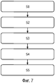
Согласно второму аспекту изобретения, представлен способ оценки риска появления повреждения ткани из-за резкого высвобождения энергии пузырьков, охарактеризованный в независимом пункте 11 формулы изобретения.According to a second aspect of the invention, there is provided a method for assessing the risk of tissue damage due to a sharp release of bubble energy, as described in independent claim 11.
Этот аспект изобретения является особенно, но не исключительно, выгодным в том, что этот способ согласно данному изобретению может быть реализован в доступном оборудовании. Кроме того, этот способ может быть реализован в автоматизированный процесс. Кроме того, так как этот способ выдает значение прогнозирующего параметра, он обеспечивает базис для решений, касающихся процесса абляции.This aspect of the invention is particularly, but not exclusively, advantageous in that this method according to this invention can be implemented in available equipment. In addition, this method can be implemented in an automated process. In addition, since this method provides the value of the predictor parameter, it provides a basis for decisions regarding the ablation process.
Ясно, что этап излучения первичного ультразвукового сигнала, такого как ультразвуковая волна, в ткань может быть проведен с использованием ультразвукового преобразователя, и, аналогично, этап приема вторичного ультразвукового сигнала, такого как ультразвуковая волна, от этой ткани, как, например, отраженного посредством этой ткани, может быть проведен с использованием ультразвукового преобразователя.It is clear that the step of emitting a primary ultrasonic signal, such as an ultrasonic wave, into a tissue can be carried out using an ultrasonic transducer, and, similarly, the step of receiving a secondary ultrasonic signal, such as an ultrasonic wave, from this tissue, such as, for example, reflected by this tissue can be carried out using an ultrasonic transducer.
В другом варианте осуществления согласно изобретению, этот способ дополнительно содержит этап, на котором выводят первичный сигнал на основе значения прогнозирующего параметра.In another embodiment according to the invention, this method further comprises the step of outputting a primary signal based on the value of the predictor parameter.
Это дает возможность количественно использовать значение прогнозирующего параметра, как, например, в системе с обратной связью.This makes it possible to quantitatively use the value of the predictor parameter, as, for example, in a feedback system.
Согласно третьему аспекту изобретения, данное изобретение относится к применению системы для комбинированного осуществления абляции и формирования ультразвуковых изображений соответствующей ткани согласно первому аспекту изобретения для управления процессом абляции.According to a third aspect of the invention, the present invention relates to the use of a system for combined ablation and ultrasound imaging of an appropriate tissue according to a first aspect of the invention for controlling an ablation process.
Согласно четвертому аспекту изобретения, представлен компьютерный программный продукт, выполненный с возможностью реализации компьютерной системы, содержащей по меньшей мере один компьютер, имеющий средство хранения данных, связанное с ним, для управления процессором, выполненным с возможностьюAccording to a fourth aspect of the invention, there is provided a computer program product configured to implement a computer system comprising at least one computer having data storage means associated therewith for controlling a processor configured to
- приема информации, извлеченной из вторичного ультразвукового сигнала, и- receiving information extracted from the secondary ultrasonic signal, and
- вычисления значения прогнозирующего параметра на основе информации, извлеченной из вторичного ультразвукового сигнала, причем значение прогнозирующего параметра относится к риску появления повреждения ткани из-за резкого высвобождения энергии пузырьков.- calculating the value of the predictive parameter based on information extracted from the secondary ultrasonic signal, and the value of the predictive parameter refers to the risk of tissue damage due to a sharp release of bubble energy.
Такой компьютерный программный продукт мог бы, например, содержать процессор, выполняющий алгоритм, при этом входные параметры могли бы содержать параметры, связанные с образованием пузырьков, а также другие параметры, такие как энергия абляции, предыдущая история ответного сигнала, измеренное усилие контакта между хирургическим устройством и соответствующей тканью, полное электрическое сопротивление соответствующей ткани, структура соответствующей ткани, длительность абляции, способность соответствующей ткани обмениваться теплом с окружающей средой, температура соответствующей ткани, при этом выходные параметры могли бы включать в себя первичный сигнал, такой как первичный сигнал, управляющий любым из: блока абляции, такого как источник энергии для абляции, потока промывки, усилия контакта, приложенного между хирургическим устройством и соответствующей тканью, положения блока абляции.Such a computer program product could, for example, comprise a processor executing an algorithm, while the input parameters could contain parameters related to the formation of bubbles, as well as other parameters such as ablation energy, previous history of the response signal, measured contact force between the surgical device and the corresponding tissue, the total electrical resistance of the corresponding tissue, the structure of the corresponding tissue, the duration of ablation, the ability of the corresponding tissue to exchange heat with the environment, the temperature of the respective tissue, while the output parameters could include a primary signal, such as a primary signal, controlling any of: an ablation unit, such as an energy source for ablation, flushing flow, contact force applied between the surgical device and appropriate tissue, the position of the ablation unit.
В одном варианте осуществления вторичным ультразвуковым сигналом является ультразвуковой импульсный эхо-сигнал.In one embodiment, the secondary ultrasonic signal is an ultrasonic pulse echo.
Каждый из первого, второго, третьего и четвертого аспектов данного изобретения может быть скомбинирован с любым из других аспектов. Эти и другие аспекты данного изобретения явствуют из вариантов осуществления, описываемых далее, и объясняются со ссылкой на них.Each of the first, second, third, and fourth aspects of the present invention may be combined with any of the other aspects. These and other aspects of the present invention are apparent from the embodiments described below, and are explained with reference to them.
КРАТКОЕ ОПИСАНИЕ ЧЕРТЕЖЕЙBRIEF DESCRIPTION OF THE DRAWINGS
Система и способ осуществления абляции и формирования ультразвуковых изображений согласно данному изобретению будут теперь описаны более подробно со ссылкой на прилагаемые чертежи. Эти чертежи показывают один способ реализации данного изобретения и не должны толковаться как ограничивающие другие возможные варианты осуществления, попадающие в пределы объема прилагаемой формулы изобретения.The system and method for performing ablation and ultrasound imaging according to this invention will now be described in more detail with reference to the accompanying drawings. These drawings show one embodiment of the present invention and should not be construed as limiting other possible embodiments falling within the scope of the attached claims.
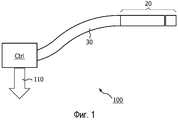
Фиг. 1 показывает систему для осуществления абляции и формирования ультразвуковых изображений согласно варианту осуществления данного изобретения;FIG. 1 shows a system for performing ablation and ultrasound imaging according to an embodiment of the present invention;
Фиг. 2 показывает хирургическое устройство согласно варианту осуществления данного изобретения;FIG. 2 shows a surgical device according to an embodiment of the present invention;
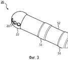
Фиг. 3 показывает перспективное изображение катетера согласно варианту осуществления данного изобретения;FIG. 3 shows a perspective view of a catheter according to an embodiment of the present invention;
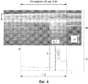
Фиг. 4 показывает экспериментальные данные, полученные от модели овцы со вскрытой грудью, согласно варианту осуществления данного изобретения;FIG. 4 shows experimental data obtained from a model of an open breast sheep according to an embodiment of the present invention;
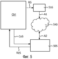
Фиг. 5 показывает схематичный чертеж системы согласно варианту осуществления данного изобретения;FIG. 5 shows a schematic drawing of a system according to an embodiment of the present invention;
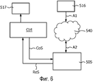
Фиг. 6 показывает другой схематичный чертеж системы согласно варианту осуществления данного изобретения;FIG. 6 shows another schematic drawing of a system according to an embodiment of the present invention;
Фиг. 7 является блок-схемой способа согласно аспекту данного изобретения; иFIG. 7 is a flowchart of a method according to an aspect of the present invention; and
Фиг. 8 показывает схематичное изображение блока управления согласно варианту осуществления данного изобретения.FIG. 8 shows a schematic illustration of a control unit according to an embodiment of the present invention.
ОСУЩЕСТВЛЕНИЕ ИЗОБРЕТЕНИЯDETAILED DESCRIPTION OF THE INVENTION
Варианты осуществления данного изобретения раскрыты в нижеследующем.Embodiments of the present invention are disclosed in the following.
Фиг. 1 показывает общую систему 100 для выполнения абляции, причем эта система содержит управляемый источник энергии для обеспечения энергии для блока абляции и/или ультразвукового преобразователя (ни один из них не показан на этом чертеже). Кроме того, примерная рукоятка 30 связана с этим источником энергии, причем эта примерная рукоятка имеет на своем периферическом конце хирургическое устройство 20 согласно варианту осуществления данного изобретения. Это хирургическое устройство может включать в себя любое из неисчерпывающегося списка, содержащего катетер, иглу, биопсийную иглу или эндоскоп. Также предполагается, что множество ультразвуковых преобразователей могло бы содержаться в пределах хирургического устройства, и некоторые ультразвуковые преобразователи могли бы быть только излучающими, тогда как другие преобразователи могли бы быть только принимающими. Система 100 дополнительно содержит блок управления (CTRL), который в некоторых вариантах осуществления выполнен с возможностью отправки первичного сигнала 110, если значение прогнозирующего параметра превышает некоторое пороговое значение.FIG. 1 shows a
Данное изобретение могло бы использоваться при формировании изображений ткани во время использования, например, в связи с аритмиями сердца или в онкологии, где является выгодным оценивание риска появления повреждения ткани из-за резкого высвобождения энергии пузырьков и, таким образом, формирование основы для решения, как управлять блоком абляции. В частности, данное изобретение может помочь в оптимизации процесса абляции, например, посредством образования части схемы с обратной связью, гарантирующей оптимальные условия во время абляции. Этим условием во время абляции может быть функция некоторого количества параметров, включая энергию абляции, температуру, поток промывки, усилие контакта между хирургическим устройством и соответствующей тканью, и положение блока абляции относительно ткани, которая подвергается абляции.This invention could be used in imaging tissue during use, for example, in connection with cardiac arrhythmias or in oncology, where it is advantageous to assess the risk of tissue damage due to a sharp release of energy from the vesicles and, thus, forming the basis for solving how manage the ablation unit. In particular, this invention can help optimize the ablation process, for example, by forming a part of a feedback circuit that guarantees optimal conditions during ablation. This condition during ablation can be a function of a number of parameters, including ablation energy, temperature, flushing flow, contact force between the surgical device and the corresponding tissue, and the position of the ablation unit relative to the tissue that is being ablated.
Фиг. 2 показывает схематичный чертеж в поперечном разрезе хирургического устройства 20; на этом конкретном чертеже хирургическим устройством является катетер, приспособленный для абляции с промыванием незамкнутого контура ткани 40. Однако следует понимать, что этим хирургическим устройством также могли бы быть другие типы хирургических устройств, такие как игла и т.п. Катетер 20 приспособлен для абляции с промыванием незамкнутого контура, например, РЧ абляции, ткани 40, причем катетер 20 имеет периферический наконечник 22, т.е. правая часть показанного катетера охвачена скобкой, где этот периферический наконечник содержит объект 15 абляции, приспособленный для выполнения абляции ткани 40. Отметим, что хотя на Фиг. 2 объект абляции изображен как покрывающий только правую часть катетера, он может также покрывать другую из сторон катетера. Излучение для выполнения абляции схематично показано пунктирной стрелкой А1. Требуемая электропроводка для снабжения энергией и/или управления объектом абляции не показана на этом чертеже для ясности. Кроме того, обеспечено отверстие 21 для промывания. Жидкость для промывания вытекает из специализированного проводника 10 жидкости для промывания, например, гибкой трубки, схематично показанной сплошной стрелкой А3. Жидкость для промывания функционирует как акустическая связывающая среда, которая может быть определена как среда, по существу прозрачная для ультразвуковых сигналов, такая как солевой раствор или вода или другие подобные жидкости, доступные для специалиста, реализующего этот вариант осуществления данного изобретения.FIG. 2 shows a schematic cross-sectional drawing of a
Далее, ультразвуковой преобразователь 5 помещен в периферическом наконечнике, причем этот преобразователь приспособлен для передачи и/или приема ультразвуковых сигналов, как схематично указано двусторонней стрелкой А2 на Фиг. 2. Согласно варианту осуществления данного изобретения, ультразвуковой преобразователь расположен позади (как на этом чертеже) или в отверстии 21 для промывания катетера 20 таким образом, чтобы дать возможность жидкости А3 для промывания вытекать из отверстия для промывания, и чтобы дать возможность осуществления передачи и/или приема ультразвуковых сигналов через то же самое отверстие 21 для промывания.Further, the
Выгодно, что катетер 20 может использоваться для радиочастотной (РЧ) абляции с промыванием незамкнутого контура.Advantageously, the
В конкретных вариантах осуществления этим катетером может быть катетер с платиновым кольцевым электродом или катетер с акустически прозрачной фольгой, такой как фольга из полиметилпентена (TPX), такой как фольга из полиметилпентена (TPX), покрытая металлическим слоем для абляции. Акустически прозрачное окно должно опосредовать контакт между катетером и тканью, и снаружи оно должно быть покрыто очень тонким (например, 150 нм) проводящим слоем, для осуществления РЧ абляции. Акустически прозрачное окно, следовательно, должно иметь существенно подобное полное акустическое сопротивление по сравнению с жидкостью для промывания (которая опосредует контакт между ультразвуковым преобразователем и внутренней стороной акустического окна), и подобное полное акустическое сопротивление по сравнению с кровью или тканью, которая встречается снаружи от акустического окна для избегания потери акустической энергии из-за отражения от этих границ раздела. Мы идентифицировали материалы, которые были бы подходящими для этой цели, включая полиметилпентен (TPX) Z=1,73 [мегарейл] и Pebax 4033 Z=1,67 [мегарейл] или 5533 Z=1,75 [мегарейл]. Кровь имеет Z=1,68 [мегарейл].In particular embodiments, the catheter may be a platinum ring electrode catheter or an acoustically transparent foil catheter, such as polymethylpentene (TPX) foil, such as polymethylpentene (TPX) foil coated with a metal layer for ablation. The acoustically transparent window should mediate the contact between the catheter and the tissue, and on the outside it should be coated with a very thin (e.g. 150 nm) conductive layer to effect RF ablation. The acoustically transparent window, therefore, must have substantially similar acoustic impedance compared to the flushing fluid (which mediates contact between the ultrasound transducer and the inside of the acoustic window), and similar acoustic impedance compared to blood or tissue that occurs outside the acoustic windows to avoid loss of acoustic energy due to reflection from these interfaces. We have identified materials that would be suitable for this purpose, including polymethylpentene (TPX) Z = 1.73 [megareil] and Pebax 4033 Z = 1.67 [megareil] or 5533 Z = 1.75 [megareil]. Blood has a Z = 1.68 [megareil].
Фиг. 3 показывает перспективное изображение катетера 20, подходящего для использования в качестве хирургического устройства согласно варианту осуществления данного изобретения. Наконечник 22 катетера смонтирован на гибкой трубке 52 для легкой манипуляции сквозь человеческое тело. Дополнительные электроды 51 в форме колец на этой трубке могут измерять свойства, подобные сопротивлению и температуре. Трубка 52 будет содержать необходимые провода для адресации преобразователей и будет подавать жидкость для промывания.FIG. 3 shows a perspective view of a
Фиг. 4 показывает экспериментальные данные от модели овцы со вскрытой грудной клеткой. Радиочастотная энергия была доставлена относительно эпикарда для создания повреждений, которые одновременно контролировались при помощи изменения ультразвука и полного электрического сопротивления. Тканевые хлопки были преднамеренно индуцированы, и данные УЗ сравнивались с данными полного сопротивления. Присутствие хлопков независимо сигнализировалось врачом, который выполнял абляцию, и который не имел доступа к данным УЗ или данным полного сопротивления. В клинической практике громкие хлопки являются слышимыми даже через грудную клетку пациента, такую как грудная клетка овцы. Этот чертеж показывает данные, полученные при помощи множества ультразвуковых измерений и соответствующих измерений полного сопротивления относящейся к эпикарду абляции при помощи интегрированного кольцевого катетера. Ультразвуковые измерения повторно визуализировались в так называемом изображении М М-режима. Показанный график G показывает временное развитие электрического полного сопротивления во время процесса абляции. Время t показано на нижней оси, и график G и изображение М М-режима совместно используют эту ось времени. РЧ энергия, рассеиваемая на временном интервале, составляет 9 ватт во время 20-секундного периода, обозначенного через t_a. Глубина ткани в изображении М М-режима обозначена через d_t. Абсолютный масштаб изображения М-режима указан посредством масштабной шкалы, обозначенной через d1, причем эта масштабная шкала соответствует 1 миллиметру. Вертикальная ось R на графике G соответствует полному электрическому сопротивлению, измеряемому в Ом. Полное электрическое сопротивление измеряется между электродом абляции и электродом заземления, который находится на спине исследуемого субъекта, как, например, на спине человека или животного, так что полное электрическое сопротивление измеряется через ткань. Обычно, полное электрическое сопротивление, измеряемое в наконечнике катетера, увеличивается в случае хлопков. Сплошная линия, обозначенная через p_i, указывает распространение тканевого хлопка; пунктирная линия, обозначенная через d_o, указывает появление изменений в ультразвуке, которые предшествуют этим хлопкам. Этот чертеж показывает, что изменения в ультразвуковых измерениях перед тканевыми хлопками предшествовали изменениям в полном сопротивлении на несколько секунд. Исходя из ультразвукового изображения М-режима, записанного во время абляционной процедуры, изменение ультразвукового сигнала могло бы быть связано с образованием пузырьков, перед тем, как врач сигнализирует это хлопок.FIG. 4 shows experimental data from an open chest model of a sheep. Radio frequency energy was delivered relative to the epicardium to create lesions that were simultaneously controlled by changes in ultrasound and total electrical resistance. Fabric claps were deliberately induced, and ultrasound data were compared with impedance data. The presence of pops was independently signaled by a doctor who performed ablation and who did not have access to ultrasound data or impedance data. In clinical practice, loud pops are audible even through the patient’s chest, such as the sheep’s chest. This drawing shows data obtained by a plurality of ultrasound measurements and corresponding measurements of the impedance of the epicardial ablation using an integrated ring catheter. Ultrasonic measurements were re-visualized in the so-called M-mode image. The graph G shown shows the temporary development of electrical impedance during the ablation process. The time t is shown on the lower axis, and the graph G and the image M of the M-mode share this time axis. The RF energy dissipated in the time interval is 9 watts during the 20 second period indicated by t_a. The tissue depth in the image of the M M-mode is indicated by d_t. The absolute scale of the M-mode image is indicated by a scale scale, denoted by d1, and this scale scale corresponds to 1 millimeter. The vertical axis R on the graph G corresponds to the total electrical resistance, measured in ohms. The total electrical resistance is measured between the ablation electrode and the ground electrode, which is located on the back of the test subject, such as on the back of a person or animal, so that the total electrical resistance is measured through the tissue. Typically, the total electrical resistance, measured at the tip of the catheter, increases in the case of pops. The solid line indicated by p_i indicates the spread of fabric cotton; the dashed line indicated by d_o indicates the appearance of changes in ultrasound that precede these pops. This drawing shows that changes in ultrasonic measurements before fabric claps preceded changes in impedance by several seconds. Based on the ultrasound image of the M-mode recorded during the ablation procedure, a change in the ultrasound signal could be associated with the formation of bubbles, before the doctor signals this clap.
Фиг. 5 показывает схематический чертеж системы согласно варианту осуществления данного изобретения, содержащей ультразвуковой преобразователь 505, блок 516 абляции, блок управления (CTRL). Кроме того, показана соответствующая ткань 540. На этом чертеже блок управления отправляет и принимает, соответственно, управляющий сигнал (CoS) и ответный сигнал (ReS) к ультразвуковому преобразователю 505 и от него, причем этот ответный сигнал указывает присутствие одного или более пузырьков в пределах упомянутой соответствующей ткани. Блок управления вычисляет значение прогнозирующего параметра, причем значение прогнозирующего параметра относится к риску появления повреждения ткани из-за резкого высвобождения энергии пузырьков, и отправляет первичный сигнал (RS), если значение прогнозирующего параметра превышает некоторое пороговое значение. В показанном варианте осуществления первичный сигнал (RS) отправляется к блоку 516 абляции. В этом варианте осуществления первичный сигнал (RS) мог бы, таким образом, служить для уменьшения энергии абляции, чтобы снизить риск появления повреждения ткани из-за резкого высвобождения энергии пузырьков.FIG. 5 shows a schematic drawing of a system according to an embodiment of the present invention, comprising an
Фиг. 6 показывает схематический чертеж системы согласно варианту осуществления данного изобретения, подобный варианту осуществления, показанному на Фиг. 5, за исключением того, что первичный сигнал отправляется к другому объекту, а не к блоку абляции. Этим другим объектом может быть любой объект, в частности, им может быть любой объект, управляющий потоком промывки, усилием контакта, приложенным между хирургическим устройством и соответствующей тканью, положением блока абляции.FIG. 6 shows a schematic drawing of a system according to an embodiment of the present invention, similar to the embodiment shown in FIG. 5, except that the primary signal is sent to another entity, and not to the ablation unit. This other object can be any object, in particular, it can be any object that controls the flushing flow, the contact force applied between the surgical device and the corresponding tissue, the position of the ablation unit.
Фиг. 7 является блок-схемой способа для выполнения абляции согласно аспекту данного изобретения. Такой способ содержит этапы, на которых:FIG. 7 is a flowchart of a method for performing ablation in accordance with an aspect of the present invention. This method contains the steps in which:
- излучают S1 первичный ультразвуковой сигнал в некоторую ткань,- emit S1 primary ultrasonic signal into some tissue,
- принимают S2 вторичный ультразвуковой сигнал от этой ткани,- take S2 a secondary ultrasonic signal from this tissue,
- определяют S3, образуется ли один или более пузырьков в пределах этой ткани, на основе информации, извлеченной из вторичного ультразвукового сигнала,- determine S3 whether one or more bubbles form within this tissue, based on information extracted from the secondary ultrasonic signal,
- отправляют S4 информацию, извлеченную из вторичного ультразвукового сигнала, процессору, и- send S4 information extracted from the secondary ultrasonic signal to the processor, and
- вычисляют S5 значение прогнозирующего параметра на основе информации, извлеченной из вторичного ультразвукового сигнала, причем значение прогнозирующего параметра относится к риску появления повреждения ткани из-за резкого высвобождения энергии пузырьков.- calculate the S5 value of the predictive parameter based on information extracted from the secondary ultrasonic signal, and the value of the predictive parameter refers to the risk of tissue damage due to a sharp release of energy from the bubbles.
Этапы S2 и S5 проводятся с использованием того представления, что обычно тканевому хлопку предшествует внезапное увеличение интенсивности от ультразвукового изображения. В конкретных вариантах осуществления анализ изображений, основанный на различных свойствах, мог бы быть применен к одному или более изображениям, основанным на ультразвуковых измерениях, для идентификации соответствующего увеличения интенсивности, включая:Steps S2 and S5 are carried out using the idea that usually tissue cotton is preceded by a sudden increase in intensity from an ultrasound image. In specific embodiments, image analysis based on various properties could be applied to one or more images based on ultrasonic measurements to identify a corresponding increase in intensity, including:
- проверку того, существует ли внезапный значительный градиент в корреляционной карте. Это изменение должно быть состоятельным в пределах определенного диапазона глубин (следовательно, отличаться от шумов); или- checking whether there is a sudden significant gradient in the correlation map. This change must be consistent within a certain range of depths (therefore, be different from noise); or
- контроль гистограммы одной или более текущих линий в изображении М-режима (так же известных, как А-линии), проверку того, имеется ли значительное изменение в полутоновом распределении по сравнению с предыдущей А-линией (линиями). Для сравнения этих гистограмм могут применяться различные метрики расстояния, такие как корреляция, хи-квадрат, расстояние Bhattacharyya и т.д. Этот подход мог бы варьироваться таким образом, чтобы включать то, что:- checking the histogram of one or more current lines in the image of the M-mode (also known as A-lines), checking whether there is a significant change in the grayscale distribution compared to the previous A-line (s). Various distance metrics such as correlation, chi-square, Bhattacharyya distance, etc., can be used to compare these histograms. This approach could be varied to include what:
эта гистограмма (распределение) не должна быть выполнена на всей А-линии. А-линия может быть сегментирована на малые сегменты, и гистограммы этих малых сегментов могут быть проверены;this histogram (distribution) should not be performed on the entire A-line. A line can be segmented into small segments, and histograms of these small segments can be checked;
в качестве альтернативы прямому сравнению распределений, среднее значение, дисперсия или моменты более высокого порядка могут использоваться для проверки различия в гистограммах; илиas an alternative to directly comparing distributions, the mean, variance, or higher order moments can be used to check for differences in histograms; or
- статистические свойства для характеризации текстуры, такие как энтропия или параметр текстуры, вычисленный из авторегрессионных моделей. Эти свойства могут использоваться как альтернативы для детектирования изменения текстуры, когда происходит тканевый хлопок.- statistical properties to characterize the texture, such as entropy or texture parameter calculated from autoregressive models. These properties can be used as alternatives to detect texture changes when fabric cotton occurs.
Вдоль единственной А-линии имеется малая вариация в интенсивности (или распределении интенсивности) вдоль глубины.Along a single A line, there is a small variation in intensity (or intensity distribution) along the depth.
Фиг. 8 показывает схематическое изображение блока управления (CTRL) согласно некоторому варианту осуществления данного изобретения, причем блок управления (CTRL) отправляет управляющий сигнал (CoS), такой как управляющий сигнал для управления ультразвуковым преобразователем (не показан), и принимает ответный сигнал (ReS), такой как сигнал, принятый от ультразвукового преобразователя, такой как сигнал, представляющий собой измеренный ультразвуковой сигнал, падающий на ультразвуковой преобразователь. В показанном варианте осуществления блок управления (CTRL) также принимает дополнительный сигнал (XS), который может быть любым из некоторого количества сигналов, таких как сигнал, характеризующий температуру, поток промывки или усилие контакта между хирургическим устройством и тканью. Блок управления (CTRL) в этом варианте осуществления использует первый вычислительный блок (С1) и второй вычислительный блок (С2), которые оба принимают как ответный сигнал (ReS), так и дополнительный сигнал (XS) для вычисления, соответственно, значения прогнозирующего параметра (PV) и порогового значения (TV). В некоторых вариантах осуществления первый вычислительный блок (С1) и второй вычислительный блок (С2) также принимают управляющий сигнал (CoS). Третий вычислительный блок (С3) сравнивает это значение прогнозирующего параметра (PV) с пороговым значением (TV) и может выдать первичный сигнал (RS), который может быть также выведен блоком управления, если значение прогнозирующего параметра (PV) превышает пороговое значение (TV).FIG. 8 shows a schematic representation of a control unit (CTRL) according to an embodiment of the present invention, wherein the control unit (CTRL) sends a control signal (CoS), such as a control signal for controlling an ultrasonic transducer (not shown), and receives a response signal (ReS), such as a signal received from an ultrasonic transducer, such as a signal representing a measured ultrasonic signal incident on an ultrasonic transducer. In the shown embodiment, the control unit (CTRL) also receives an additional signal (XS), which may be any of a number of signals, such as a signal indicative of temperature, flushing flow, or contact force between the surgical device and tissue. The control unit (CTRL) in this embodiment uses a first computing unit (C1) and a second computing unit (C2), which both receive both a response signal (ReS) and an additional signal (XS) to calculate, respectively, the value of the predictor parameter ( PV) and threshold value (TV). In some embodiments, the first computing unit (C1) and the second computing unit (C2) also receive a control signal (CoS). The third computing unit (C3) compares this value of the predictive parameter (PV) with a threshold value (TV) and can provide a primary signal (RS), which can also be output by the control unit if the value of the predictive parameter (PV) exceeds the threshold value (TV) .
В итоге, данное изобретение относится к системе (100) для комбинированного осуществления абляции и формирования ультразвуковых изображений соответствующей ткани (40), которая особенно полезна для использования в процессе абляции. Эта система содержит хирургическое устройство (20) с ультразвуковым преобразователем и блоком абляции. Во время процесса абляции это хирургическое устройство (20) может быть применено как для абляции, так и для формирования изображений ткани (40), подвергнутой абляции. Блок управления (CTRL) дополнительно содержится в пределах этой системы и выполнен с возможностью вычисления значения прогнозирующего параметра на основе одного или более сигналов от ультразвукового преобразователя, причем значение прогнозирующего параметра относится к риску появления повреждения ткани из-за резкого высвобождения энергии пузырьков. Согласно определенному варианту осуществления, первичный сигнал отправляется, если значение прогнозирующего параметра превышает некоторое пороговое значение, так что могут быть предприняты правильные меры.As a result, this invention relates to a system (100) for the combined implementation of ablation and the formation of ultrasound images of the corresponding tissue (40), which is especially useful for use in the ablation process. This system comprises a surgical device (20) with an ultrasound transducer and an ablation unit. During the ablation process, this surgical device (20) can be used both for ablation and for imaging tissue (40) subjected to ablation. A control unit (CTRL) is additionally contained within this system and is configured to calculate a predictive parameter value based on one or more signals from an ultrasonic transducer, the predictive parameter value relating to the risk of tissue damage due to a sharp release of bubble energy. According to a particular embodiment, a primary signal is sent if the value of the predictor parameter exceeds a certain threshold value, so that the right measures can be taken.
Хотя данное изобретение было описано в связи с определенными вариантами осуществления, оно не должно толковаться как каким-либо образом ограниченное представленными примерами. Объем данного изобретения устанавливается прилагаемой формулой изобретения. В контексте этой формулы изобретения термин «содержащий» или «содержит» не исключает других возможных элементов или этапов. Также, использование элементов в единственном числе не исключает наличия множества таких элементов. Использование знаков ссылки в формуле изобретения в отношении элементов, указанных на чертежах, также не должно толковаться как ограничивающее объем данного изобретения. Кроме того, индивидуальные особенности, упомянутые в различных пунктах формулы изобретения, возможно, могут быть выгодно скомбинированы, и упоминание этих особенностей в различных пунктах формулы изобретения не исключает того, что некоторая комбинация особенностей не является возможной и выгодной.Although the invention has been described in connection with certain embodiments, it should not be construed as in any way limited by the examples presented. The scope of this invention is established by the attached claims. In the context of this claims, the term “comprising” or “comprises” does not exclude other possible elements or steps. Also, the use of elements in the singular does not exclude the presence of many such elements. The use of reference marks in the claims in relation to the elements indicated in the drawings is also not to be construed as limiting the scope of the invention. In addition, the individual features mentioned in the various claims may possibly be advantageously combined, and the mention of these features in the various claims does not exclude the possibility that some combination of features is not possible and advantageous.
Claims (12)
хирургическое устройство (20), содержащее:
ультразвуковой преобразователь (5, 505) и
блок (15, 516) абляции, и
блок управления (CTRL), функционально связанный с хирургическим устройством (20), причем блок управления (CTRL) выполнен с возможностью
отправки управляющего сигнала (CoS) к ультразвуковому преобразователю (5, 505),
приема ответного сигнала (ReS) от ультразвукового преобразователя, причем ответный сигнал (ReS) указывает присутствие одного или более пузырьков в пределах упомянутой соответствующей ткани (40, 540), и
вычисления значения прогнозирующего параметра (PV), относящегося к риску появления повреждения ткани из-за резкого высвобождения энергии пузырьков,
при этом блок управления (CTRL) дополнительно выполнен с возможностью отправки первичного сигнала (RS), если значение прогнозирующего параметра (PV) превышает пороговое значение,
при этом первичный сигнал (RS) выполнен с возможностью управления положением блока абляции.1. System (100) for the combined implementation of ablation and the formation of ultrasound images of the corresponding tissue (40, 540), the system comprising:
a surgical device (20), comprising:
ultrasonic transducer (5, 505) and
an ablation unit (15, 516), and
a control unit (CTRL) operably connected to the surgical device (20), the control unit (CTRL) being configured to
sending a control signal (CoS) to the ultrasonic transducer (5, 505),
receiving a response signal (ReS) from the ultrasound transducer, the response signal (ReS) indicating the presence of one or more bubbles within the corresponding tissue (40, 540), and
calculating a value of a predictor parameter (PV) related to the risk of tissue damage due to a sharp release of bubble energy,
wherein the control unit (CTRL) is further configured to send a primary signal (RS) if the value of the predictor parameter (PV) exceeds a threshold value,
wherein the primary signal (RS) is configured to control the position of the ablation unit.
испускают (S1) первичный ультразвуковой сигнал в ткань,
принимают (S2) вторичный ультразвуковой сигнал от этой ткани,
определяют (S3), образуется ли один или более пузырьков в пределах этой ткани, на основе информации, извлеченной из вторичного ультразвукового сигнала,
отправляют (S4) информацию, извлеченную из вторичного ультразвукового сигнала, процессору,
вычисляют (S5) значение прогнозирующего параметра (PV) на основе информации, извлеченной из вторичного ультразвукового сигнала, причем значение прогнозирующего параметра (PV) относится к риску появления повреждения ткани из-за резкого высвобождения энергии пузырьков,
выводят первичный сигнал (RS) на основе значения прогнозирующего параметра (PV),
управляют положением блока абляции с помощью первичного сигнала (RS).11. A method for assessing the risk of tissue damage due to a sharp release of energy from the bubbles, the method comprising the steps of:
emit (S1) a primary ultrasonic signal into the tissue,
receive (S2) a secondary ultrasound signal from this tissue,
determining (S3) whether one or more bubbles are formed within the tissue based on information extracted from the secondary ultrasound signal,
send (S4) information extracted from the secondary ultrasonic signal to the processor,
calculating (S5) the value of the predictive parameter (PV) based on information extracted from the secondary ultrasonic signal, the value of the predictive parameter (PV) refers to the risk of tissue damage due to a sharp release of energy from the bubbles,
outputting the primary signal (RS) based on the value of the predictor parameter (PV),
control the position of the ablation unit using a primary signal (RS).
Applications Claiming Priority (3)
| Application Number | Priority Date | Filing Date | Title |
|---|---|---|---|
| EP10152815.6 | 2010-02-05 | ||
| EP10152815 | 2010-02-05 | ||
| PCT/IB2011/050462 WO2011095937A1 (en) | 2010-02-05 | 2011-02-03 | Combined ablation and ultrasound imaging |
Publications (2)
| Publication Number | Publication Date |
|---|---|
| RU2012137787A RU2012137787A (en) | 2014-03-10 |
| RU2576440C2 true RU2576440C2 (en) | 2016-03-10 |
Family
ID=44170498
Family Applications (1)
| Application Number | Title | Priority Date | Filing Date |
|---|---|---|---|
| RU2012137787/14A RU2576440C2 (en) | 2010-02-05 | 2011-02-03 | Combination of ablation and ultrasonic image arrangement |
Country Status (7)
| Country | Link |
|---|---|
| US (1) | US10383687B2 (en) |
| EP (1) | EP2531133B1 (en) |
| JP (1) | JP6472940B2 (en) |
| CN (1) | CN102781358B (en) |
| BR (1) | BR112012019262A2 (en) |
| RU (1) | RU2576440C2 (en) |
| WO (1) | WO2011095937A1 (en) |
Cited By (1)
| Publication number | Priority date | Publication date | Assignee | Title |
|---|---|---|---|---|
| RU2654764C2 (en) * | 2016-08-17 | 2018-05-22 | Федеральное государственное бюджетное образовательное учреждение высшего образования "Саратовский национальный исследовательский государственный университет имени Н.Г. Чернышевского" | Method of laser ablation of the pathological area of heart |
Families Citing this family (45)
| Publication number | Priority date | Publication date | Assignee | Title |
|---|---|---|---|---|
| US9795442B2 (en) | 2008-11-11 | 2017-10-24 | Shifamed Holdings, Llc | Ablation catheters |
| JP5693471B2 (en) | 2009-02-11 | 2015-04-01 | ボストン サイエンティフィック サイムド,インコーポレイテッドBoston Scientific Scimed,Inc. | Insulated ablation catheter device and use thereof |
| US9277961B2 (en) | 2009-06-12 | 2016-03-08 | Advanced Cardiac Therapeutics, Inc. | Systems and methods of radiometrically determining a hot-spot temperature of tissue being treated |
| US8926605B2 (en) | 2012-02-07 | 2015-01-06 | Advanced Cardiac Therapeutics, Inc. | Systems and methods for radiometrically measuring temperature during tissue ablation |
| US8954161B2 (en) | 2012-06-01 | 2015-02-10 | Advanced Cardiac Therapeutics, Inc. | Systems and methods for radiometrically measuring temperature and detecting tissue contact prior to and during tissue ablation |
| US9226791B2 (en) | 2012-03-12 | 2016-01-05 | Advanced Cardiac Therapeutics, Inc. | Systems for temperature-controlled ablation using radiometric feedback |
| EP3106116B1 (en) | 2009-06-30 | 2018-08-01 | Boston Scientific Scimed, Inc. | Map and ablate open irrigated hybrid catheter |
| US9655677B2 (en) | 2010-05-12 | 2017-05-23 | Shifamed Holdings, Llc | Ablation catheters including a balloon and electrodes |
| JP5792802B2 (en) | 2010-05-12 | 2015-10-14 | シファメド・ホールディングス・エルエルシー | Low profile electrode assembly |
| US9089340B2 (en) | 2010-12-30 | 2015-07-28 | Boston Scientific Scimed, Inc. | Ultrasound guided tissue ablation |
| US9241687B2 (en) | 2011-06-01 | 2016-01-26 | Boston Scientific Scimed Inc. | Ablation probe with ultrasonic imaging capabilities |
| CA2848053A1 (en) | 2011-09-14 | 2013-03-21 | Boston Scientific Scimed, Inc. | Ablation device with ionically conductive balloon |
| CN103987336A (en) | 2011-09-14 | 2014-08-13 | 波士顿科学西美德公司 | Ablation device with multiple ablation modes |
| US9241761B2 (en) | 2011-12-28 | 2016-01-26 | Koninklijke Philips N.V. | Ablation probe with ultrasonic imaging capability |
| CA2860636A1 (en) | 2012-01-10 | 2013-07-18 | Boston Scientific Scimed, Inc. | Electrophysiology system |
| US8945015B2 (en) | 2012-01-31 | 2015-02-03 | Koninklijke Philips N.V. | Ablation probe with fluid-based acoustic coupling for ultrasonic tissue imaging and treatment |
| EP2866669A4 (en) | 2012-06-30 | 2016-04-20 | Cibiem Inc | Carotid body ablation via directed energy |
| US9955946B2 (en) | 2014-03-12 | 2018-05-01 | Cibiem, Inc. | Carotid body ablation with a transvenous ultrasound imaging and ablation catheter |
| JP6042023B2 (en) | 2013-03-15 | 2016-12-14 | セント・ジュード・メディカル・エイトリアル・フィブリレーション・ディヴィジョン・インコーポレーテッド | Force sensing ablation catheter |
| JP6463731B2 (en) | 2013-04-08 | 2019-02-06 | アパマ・メディカル・インコーポレーテッド | Imaging system |
| US10349824B2 (en) | 2013-04-08 | 2019-07-16 | Apama Medical, Inc. | Tissue mapping and visualization systems |
| US10098694B2 (en) | 2013-04-08 | 2018-10-16 | Apama Medical, Inc. | Tissue ablation and monitoring thereof |
| US10945660B2 (en) | 2014-03-27 | 2021-03-16 | Koninklijke Philips N.V. | Normalized-displacement-difference-based approach for thermal lesion size control |
| EP3206612B1 (en) | 2014-10-13 | 2022-06-29 | Boston Scientific Scimed Inc. | Tissue diagnosis and treatment using mini-electrodes |
| CN106604675B (en) | 2014-10-24 | 2020-01-10 | 波士顿科学医学有限公司 | Medical device having a flexible electrode assembly coupled to an ablation tip |
| WO2016081606A1 (en) | 2014-11-19 | 2016-05-26 | Advanced Cardiac Therapeutics, Inc. | Systems and methods for high-resolution mapping of tissue |
| CA2967824A1 (en) | 2014-11-19 | 2016-05-26 | Advanced Cardiac Therapeutics, Inc. | Ablation devices, systems and methods of using a high-resolution electrode assembly |
| WO2016081611A1 (en) | 2014-11-19 | 2016-05-26 | Advanced Cardiac Therapeutics, Inc. | High-resolution mapping of tissue with pacing |
| WO2016100917A1 (en) | 2014-12-18 | 2016-06-23 | Boston Scientific Scimed Inc. | Real-time morphology analysis for lesion assessment |
| WO2016131636A1 (en) * | 2015-02-17 | 2016-08-25 | Koninklijke Philips N.V. | Device and method for assisting in tissue ablation |
| US9636164B2 (en) | 2015-03-25 | 2017-05-02 | Advanced Cardiac Therapeutics, Inc. | Contact sensing systems and methods |
| EP3376936B1 (en) | 2015-11-16 | 2024-01-03 | Boston Scientific Scimed, Inc. | Energy delivery devices |
| US11160607B2 (en) | 2015-11-20 | 2021-11-02 | Biosense Webster (Israel) Ltd. | Hyper-apertured ablation electrode |
| JP6923549B2 (en) | 2016-03-15 | 2021-08-18 | エピックス セラピューティクス,インコーポレイテッド | Improved system for irrigation cauterization |
| US10939956B2 (en) | 2016-05-02 | 2021-03-09 | Affera, Inc. | Pulsed radiofrequency ablation |
| US20180235576A1 (en) * | 2017-02-22 | 2018-08-23 | Covidien Lp | Ultrasound doppler and elastography for ablation prediction and monitoring |
| EP3614946B1 (en) | 2017-04-27 | 2024-03-20 | EPiX Therapeutics, Inc. | Determining nature of contact between catheter tip and tissue |
| US11819360B2 (en) * | 2017-08-15 | 2023-11-21 | Koninklijke Philips N.V. | Intraluminal rotational ultrasound for diagnostic imaging and therapy |
| US10828020B2 (en) | 2018-08-22 | 2020-11-10 | Covidien Lp | Surgical retractor including three-dimensional (3D) imaging capability |
| US11298106B2 (en) | 2018-08-31 | 2022-04-12 | Covidien Lp | Minimally-invasive surgical instrument including three-dimensional (3D) ultrasound imaging and focused ultrasound treatment capabilities |
| CN110755148B (en) * | 2019-09-20 | 2020-09-08 | 姚陈果 | Pulsed electric field tumor ablation parameter optimization system |
| EP4171419A1 (en) * | 2020-06-30 | 2023-05-03 | Koninklijke Philips N.V. | Systems for laser catheter treatment in a vessel lumen |
| US11051883B1 (en) * | 2020-11-18 | 2021-07-06 | Endra Life Sciences Inc. | Thermal ablation system and method with integrated thermoacoustic temperature measurement |
| USD1014762S1 (en) | 2021-06-16 | 2024-02-13 | Affera, Inc. | Catheter tip with electrode panel(s) |
| CN114587565B (en) * | 2022-03-01 | 2023-09-29 | 河南中医药大学 | Temperature control method and system in radio frequency ablation |
Citations (2)
| Publication number | Priority date | Publication date | Assignee | Title |
|---|---|---|---|---|
| RU2002107969A (en) * | 2002-03-29 | 2003-12-20 | Общество с ограниченной ответственностью "АММ-2000" | METHOD AND DEVICE FOR OBTAINING ULTRASONIC IMAGES OF THE BRAIN STRUCTURES AND VESSELS |
| WO2008017990A1 (en) * | 2006-08-11 | 2008-02-14 | Koninklijke Philips Electronics, N.V. | Image-based power feedback for optimal ultrasound imaging of radio frequency tissue ablation |
Family Cites Families (14)
| Publication number | Priority date | Publication date | Assignee | Title |
|---|---|---|---|---|
| GB9106686D0 (en) | 1991-03-28 | 1991-05-15 | Hafslund Nycomed As | Improvements in or relating to contrast agents |
| US5246436A (en) * | 1991-12-18 | 1993-09-21 | Alcon Surgical, Inc. | Midinfrared laser tissue ablater |
| US20080154257A1 (en) | 2006-12-22 | 2008-06-26 | Shiva Sharareh | Real-time optoacoustic monitoring with electophysiologic catheters |
| AU2001251134B2 (en) * | 2000-03-31 | 2006-02-02 | Angiodynamics, Inc. | Tissue biopsy and treatment apparatus and method |
| RU2232547C2 (en) * | 2002-03-29 | 2004-07-20 | Общество с ограниченной ответственностью "АММ - 2000" | Method and device for making ultrasonic images of cerebral structures and blood vessels |
| US6709432B2 (en) | 2002-04-26 | 2004-03-23 | Medtronic, Inc. | Ablation methods and medical apparatus using same |
| CN1901837B (en) * | 2003-12-30 | 2010-05-12 | 利普索尼克斯股份有限公司 | Component ultrasound transducer |
| US20050283074A1 (en) | 2004-06-22 | 2005-12-22 | Siemens Medical Solutions Usa, Inc. | Ultrasound feedback for tissue ablation procedures |
| US7918850B2 (en) * | 2006-02-17 | 2011-04-05 | Biosense Wabster, Inc. | Lesion assessment by pacing |
| CA2652126C (en) * | 2006-05-12 | 2015-12-01 | Hira V. Thapliyal | Device for ablating body tissue |
| WO2008017992A2 (en) | 2006-08-11 | 2008-02-14 | Koninklijke Philips Electronics, N.V. | Systems and methods for associating nucleic acid profiles and proteomic profiles with healthcare protocols and guidelines in a decision support system |
| WO2008141238A1 (en) * | 2007-05-11 | 2008-11-20 | Voyage Medical, Inc. | Visual electrode ablation systems |
| US20090287205A1 (en) * | 2008-05-16 | 2009-11-19 | Boston Scientific Scimed, Inc. | Systems and methods for preventing tissue popping caused by bubble expansion during tissue ablation |
| US8414508B2 (en) * | 2008-10-30 | 2013-04-09 | Vytronus, Inc. | System and method for delivery of energy to tissue while compensating for collateral tissue |
-
2011
- 2011-02-03 CN CN201180008102.2A patent/CN102781358B/en not_active Expired - Fee Related
- 2011-02-03 JP JP2012551723A patent/JP6472940B2/en not_active Expired - Fee Related
- 2011-02-03 WO PCT/IB2011/050462 patent/WO2011095937A1/en active Application Filing
- 2011-02-03 RU RU2012137787/14A patent/RU2576440C2/en not_active IP Right Cessation
- 2011-02-03 BR BR112012019262-0A patent/BR112012019262A2/en not_active IP Right Cessation
- 2011-02-03 US US13/576,022 patent/US10383687B2/en not_active Expired - Fee Related
- 2011-02-03 EP EP11708323.8A patent/EP2531133B1/en not_active Not-in-force
Patent Citations (2)
| Publication number | Priority date | Publication date | Assignee | Title |
|---|---|---|---|---|
| RU2002107969A (en) * | 2002-03-29 | 2003-12-20 | Общество с ограниченной ответственностью "АММ-2000" | METHOD AND DEVICE FOR OBTAINING ULTRASONIC IMAGES OF THE BRAIN STRUCTURES AND VESSELS |
| WO2008017990A1 (en) * | 2006-08-11 | 2008-02-14 | Koninklijke Philips Electronics, N.V. | Image-based power feedback for optimal ultrasound imaging of radio frequency tissue ablation |
Non-Patent Citations (1)
| Title |
|---|
| J.S.Wolf Jr et al.Pulsed Cavitational Ultrasound: A Noninvasive Technology for Controlled Tissue Ablation (Histotripsy) in the Rabbit Kidney, Volume 175, Issue 2, February 2006, Pages 734-738. * |
Cited By (1)
| Publication number | Priority date | Publication date | Assignee | Title |
|---|---|---|---|---|
| RU2654764C2 (en) * | 2016-08-17 | 2018-05-22 | Федеральное государственное бюджетное образовательное учреждение высшего образования "Саратовский национальный исследовательский государственный университет имени Н.Г. Чернышевского" | Method of laser ablation of the pathological area of heart |
Also Published As
| Publication number | Publication date |
|---|---|
| US20120302877A1 (en) | 2012-11-29 |
| EP2531133A1 (en) | 2012-12-12 |
| WO2011095937A1 (en) | 2011-08-11 |
| CN102781358B (en) | 2015-06-24 |
| JP6472940B2 (en) | 2019-02-20 |
| BR112012019262A2 (en) | 2021-03-09 |
| RU2012137787A (en) | 2014-03-10 |
| CN102781358A (en) | 2012-11-14 |
| US10383687B2 (en) | 2019-08-20 |
| JP2013518659A (en) | 2013-05-23 |
| EP2531133B1 (en) | 2015-04-08 |
Similar Documents
| Publication | Publication Date | Title |
|---|---|---|
| RU2576440C2 (en) | Combination of ablation and ultrasonic image arrangement | |
| RU2572748C2 (en) | Power-supply device for power supply to object | |
| RU2539010C2 (en) | Device, method and computer program for cardiac value measurement | |
| US9662170B2 (en) | Sensing apparatus for sensing an object | |
| US11497464B2 (en) | Medical ultrasound device with temperature detection at distal end | |
| RU2567268C2 (en) | Property-determining device for determination of object property | |
| JP6548948B2 (en) | Prevention of steam pop during ablation | |
| JP6956160B2 (en) | Energy imparting device | |
| AU2015268763B2 (en) | Measurement of tissue thickness using ultrasound and force measurements | |
| EP1643912B1 (en) | A combination of a therapy and an imaging instrument | |
| US9087369B2 (en) | Apparatus for being used for detecting a property of an object | |
| EP3226773B1 (en) | Systems for lesion formation feedback |
Legal Events
| Date | Code | Title | Description |
|---|---|---|---|
| HC9A | Changing information about inventors | ||
| MM4A | The patent is invalid due to non-payment of fees |
Effective date: 20200204 |