RU2534175C2 - Device and method for removal of debris from borehole fluid in well borehole - Google Patents
Device and method for removal of debris from borehole fluid in well borehole Download PDFInfo
- Publication number
- RU2534175C2 RU2534175C2 RU2012134086/03A RU2012134086A RU2534175C2 RU 2534175 C2 RU2534175 C2 RU 2534175C2 RU 2012134086/03 A RU2012134086/03 A RU 2012134086/03A RU 2012134086 A RU2012134086 A RU 2012134086A RU 2534175 C2 RU2534175 C2 RU 2534175C2
- Authority
- RU
- Russia
- Prior art keywords
- separator
- inner pipe
- fluid
- debris
- unit
- Prior art date
Links
- 239000012530 fluid Substances 0.000 title claims abstract description 82
- 238000000034 method Methods 0.000 title claims description 11
- 239000012634 fragment Substances 0.000 claims description 14
- 239000003381 stabilizer Substances 0.000 claims description 5
- 238000004891 communication Methods 0.000 claims description 4
- 238000005553 drilling Methods 0.000 abstract description 26
- 230000000694 effects Effects 0.000 abstract description 6
- 238000004140 cleaning Methods 0.000 abstract description 4
- 239000000126 substance Substances 0.000 abstract description 2
- 239000004576 sand Substances 0.000 description 6
- 238000003801 milling Methods 0.000 description 4
- 230000008439 repair process Effects 0.000 description 3
- 241000332308 Pisauridae Species 0.000 description 2
- 238000005520 cutting process Methods 0.000 description 2
- 238000004519 manufacturing process Methods 0.000 description 2
- 210000000056 organ Anatomy 0.000 description 2
- 239000007787 solid Substances 0.000 description 2
- 239000000243 solution Substances 0.000 description 2
- 241000239290 Araneae Species 0.000 description 1
- 230000009471 action Effects 0.000 description 1
- 230000006835 compression Effects 0.000 description 1
- 238000007906 compression Methods 0.000 description 1
- 230000003670 easy-to-clean Effects 0.000 description 1
- 238000001914 filtration Methods 0.000 description 1
- 239000008187 granular material Substances 0.000 description 1
- 238000002347 injection Methods 0.000 description 1
- 239000007924 injection Substances 0.000 description 1
- 239000007788 liquid Substances 0.000 description 1
- 238000012423 maintenance Methods 0.000 description 1
- 239000000463 material Substances 0.000 description 1
- 230000007246 mechanism Effects 0.000 description 1
- 239000000203 mixture Substances 0.000 description 1
- 239000002245 particle Substances 0.000 description 1
- 239000011236 particulate material Substances 0.000 description 1
- 238000005192 partition Methods 0.000 description 1
- 238000005381 potential energy Methods 0.000 description 1
- 238000011084 recovery Methods 0.000 description 1
- 239000011435 rock Substances 0.000 description 1
- 230000007704 transition Effects 0.000 description 1
- 230000001960 triggered effect Effects 0.000 description 1
- XLYOFNOQVPJJNP-UHFFFAOYSA-N water Substances O XLYOFNOQVPJJNP-UHFFFAOYSA-N 0.000 description 1
Images


Classifications
-
- E—FIXED CONSTRUCTIONS
- E21—EARTH OR ROCK DRILLING; MINING
- E21B—EARTH OR ROCK DRILLING; OBTAINING OIL, GAS, WATER, SOLUBLE OR MELTABLE MATERIALS OR A SLURRY OF MINERALS FROM WELLS
- E21B27/00—Containers for collecting or depositing substances in boreholes or wells, e.g. bailers, baskets or buckets for collecting mud or sand; Drill bits with means for collecting substances, e.g. valve drill bits
- E21B27/005—Collecting means with a strainer
-
- E—FIXED CONSTRUCTIONS
- E21—EARTH OR ROCK DRILLING; MINING
- E21B—EARTH OR ROCK DRILLING; OBTAINING OIL, GAS, WATER, SOLUBLE OR MELTABLE MATERIALS OR A SLURRY OF MINERALS FROM WELLS
- E21B21/00—Methods or apparatus for flushing boreholes, e.g. by use of exhaust air from motor
- E21B21/10—Valve arrangements in drilling-fluid circulation systems
- E21B21/103—Down-hole by-pass valve arrangements, i.e. between the inside of the drill string and the annulus
-
- E—FIXED CONSTRUCTIONS
- E21—EARTH OR ROCK DRILLING; MINING
- E21B—EARTH OR ROCK DRILLING; OBTAINING OIL, GAS, WATER, SOLUBLE OR MELTABLE MATERIALS OR A SLURRY OF MINERALS FROM WELLS
- E21B21/00—Methods or apparatus for flushing boreholes, e.g. by use of exhaust air from motor
- E21B21/12—Methods or apparatus for flushing boreholes, e.g. by use of exhaust air from motor using drilling pipes with plural fluid passages, e.g. closed circulation systems
-
- E—FIXED CONSTRUCTIONS
- E21—EARTH OR ROCK DRILLING; MINING
- E21B—EARTH OR ROCK DRILLING; OBTAINING OIL, GAS, WATER, SOLUBLE OR MELTABLE MATERIALS OR A SLURRY OF MINERALS FROM WELLS
- E21B37/00—Methods or apparatus for cleaning boreholes or wells
-
- E—FIXED CONSTRUCTIONS
- E21—EARTH OR ROCK DRILLING; MINING
- E21B—EARTH OR ROCK DRILLING; OBTAINING OIL, GAS, WATER, SOLUBLE OR MELTABLE MATERIALS OR A SLURRY OF MINERALS FROM WELLS
- E21B41/00—Equipment or details not covered by groups E21B15/00 - E21B40/00
- E21B41/0078—Nozzles used in boreholes
-
- E—FIXED CONSTRUCTIONS
- E21—EARTH OR ROCK DRILLING; MINING
- E21B—EARTH OR ROCK DRILLING; OBTAINING OIL, GAS, WATER, SOLUBLE OR MELTABLE MATERIALS OR A SLURRY OF MINERALS FROM WELLS
- E21B2200/00—Special features related to earth drilling for obtaining oil, gas or water
- E21B2200/06—Sleeve valves
Landscapes
- Engineering & Computer Science (AREA)
- Life Sciences & Earth Sciences (AREA)
- Geology (AREA)
- Mining & Mineral Resources (AREA)
- Physics & Mathematics (AREA)
- Environmental & Geological Engineering (AREA)
- Fluid Mechanics (AREA)
- General Life Sciences & Earth Sciences (AREA)
- Geochemistry & Mineralogy (AREA)
- Mechanical Engineering (AREA)
- Jet Pumps And Other Pumps (AREA)
- Earth Drilling (AREA)
- Filtration Of Liquid (AREA)
- Branch Pipes, Bends, And The Like (AREA)
- Cleaning In General (AREA)
- Cyclones (AREA)
- Processing Of Stones Or Stones Resemblance Materials (AREA)
- Sink And Installation For Waste Water (AREA)
- Powder Metallurgy (AREA)
- Sewage (AREA)
Abstract
Description
Эта заявка заявляет о приоритете предварительной заявки США на патент №61/296878, поданной 20 января 2010 г. под названием «Сепараторная камера в стволе скважины и способы ее применения» и включенной сюда в полном объеме путем ссылки на нее.This application claims the priority of provisional patent application US No. 61/296878, filed January 20, 2010 under the name "Separator chamber in the wellbore and methods of its application" and incorporated herein in full by reference.
Область техники, к которой относится изобретениеFIELD OF THE INVENTION
Настоящее изобретение относится, в общем, к усовершенствованным приспособлениям повышенной мощности для удаления обломков из ствола скважины и способам их применения. Обычно предлагаемые приспособления подсоединяют к насосно-компрессорной колонне, такой как бурильная колонна, чтобы можно было их использовать глубоко в скважине для удаления из нее породы.The present invention relates, in General, to improved devices with increased power for removing debris from the wellbore and methods for their use. Typically, the proposed devices are connected to a tubing string, such as a drill string, so that they can be used deep in the well to remove rock from it.
Уровень техникиState of the art
При проведении скважинных операций, таких как фрезерование инструментов, попавших в скважину или гидравлический разрыв пласта, образуется обломки породы, которые необходимо собирать и удалять из скважины. Например, забойный агрегат с фрезой снабжен приспособлением для сбора обломков. Приспособления для сбора обломков иногда называют ловильными пауками, коллекторными пауками или противопесочными фильтрами. Существует множество разных ловильных приспособлений, которые работают по разному принципу. Но, в общем, все эти приспособления предназначены для одной и той же цели отделения циркулирующего флюида от обломков выбуренной породы и/или от других обломков, оказавшихся в стволе скважины. В некоторых приспособлениях на нижнем конце насосно-компрессорной колонны обеспечивают обратную циркуляцию и используют ее для перемещения обломков с циркулирующим флюидом в улавливающее приспособление. Обратную циркуляцию обычно обеспечивают с помощью приспособления, называемого иногда приводной головкой, чтобы можно было направлять поток, несущий обломки и/или зернистый материал, в агрегат для удаления обломков.When conducting downhole operations, such as milling tools that have fallen into the well or hydraulic fracturing, debris is formed that must be collected and removed from the well. For example, a downhole aggregate with a mill is equipped with a device for collecting debris. Debris collection tools are sometimes called fishing spiders, collector spiders or sand filters. There are many different fishing devices that work on different principles. But, in general, all these devices are designed for the same purpose of separating the circulating fluid from the cuttings of the cuttings and / or from other fragments that are in the wellbore. Some devices at the lower end of the tubing string provide reverse circulation and use it to move the debris with the circulating fluid into the recovery device. Reverse circulation is usually provided by means of a device, sometimes called a drive head, so that a stream carrying debris and / or granular material can be directed to the debris removal unit.
Описание вариантов осуществления и раскрытие сущности предлагаемых устройств для удаления обломков и вакуумных устройств приведено в патентах США: U.S. 2915127; U.S. 2771141; U.S. 2915127; U.S. 3023810; U.S. 3382925; U.S. 4059155; U.S. 5176208; U.S. 5402850; U.S. 5944100; U.S. 6176311; U.S. 6276452; U.S. 6341653; U.S. 6962197; U.S. 7472745; в заявках: U.S. 2007/0272404A1 и U.S. 2009/0126933A1, содержимое которых тем самым включено сюда путем ссылки на них по любому назначению, как если бы они были бы представлены здесь во всей своей полноте. Однако в данной области все еще продолжается поиск подходящих приспособлений для удаления обломков из скважины.Description of embodiments and disclosure of the essence of the proposed devices for removing debris and vacuum devices are given in US patents: U.S. 2,915,127; U.S. 2,771,141; U.S. 2,915,127; U.S. 3,023,810; U.S. 3,382,925; U.S. 4,059,155; U.S. 5,176,208; U.S. 5402850; U.S. 5,944,100; U.S. 6176311; U.S. 6,276,452; U.S. 6341653; U.S. 6962197; U.S. 7472745; in applications: U.S. 2007 / 0272404A1 and U.S. 2009 / 0126933A1, the contents of which are hereby incorporated by reference to them for any purpose, as if they would be presented here in their entirety. However, in this area the search for suitable devices for removing debris from the well is still ongoing.
Раскрытие изобретенияDisclosure of invention
В общем, разные варианты осуществления настоящего изобретения включают: приводную головку, содержащую центральный проточный канал, по меньшей мере, одну подъемную колонну с проточным каналом, проходящим параллельно центральному проточному каналу, и, по меньшей мере, одно выпускное отверстие. Клапан способен направлять поток в подъемную колонну и открывать выпускное отверстие, пропуская поток через подъемную колонну в кольцевой зазор. Подъемная колонна расположена таким образом, чтобы создавать область с пониженным давлением и обеспечивать обратную циркуляцию для перемещения обломков в приспособление для сбора обломков. Приспособление для сбора обломков содержит усовершенствованные фильтровальный и сепараторный агрегаты.In general, various embodiments of the present invention include: a drive head comprising a central flow channel, at least one lifting column with a flow channel parallel to the central flow channel, and at least one outlet. The valve is able to direct the flow into the lifting column and open the outlet, passing the flow through the lifting column into the annular gap. The lifting column is positioned so as to create an area with reduced pressure and to provide reverse circulation to move the debris into the debris collection device. The debris collection device contains advanced filter and separator units.
Эти и другие особенности и преимущества этих изобретений будут понятны сведущим в данной области из приведенного далее подробного описания предпочтительных вариантов осуществления, снабженного ссылками на прилагаемые чертежи, и из формулы изобретения.These and other features and advantages of these inventions will be apparent to those skilled in the art from the following detailed description of preferred embodiments provided with reference to the accompanying drawings, and from the claims.
Краткое описание графических материаловA brief description of the graphic materials
Все чертежи в настоящем изобретении выполнены без соблюдения масштаба, если только нет других указаний. Понятно, что на этих чертежах показаны только характерные варианты осуществления этого изобретения, а следовательно, их нельзя считать ограничивающими объем этого изобретения, которое будет описано более конкретно и более подробно с использованием прилагаемых чертежи.All drawings in the present invention are made to scale, unless otherwise indicated. It is understood that in these drawings only representative embodiments of this invention are shown, and therefore, they cannot be considered as limiting the scope of this invention, which will be described more specifically and in more detail using the accompanying drawings.
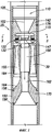
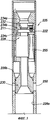
На фиг.1 приведено поперечное сечение варианта осуществления предлагаемой приводной головки в закрытом положении.Figure 1 shows a cross section of an embodiment of the proposed drive head in the closed position.
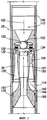
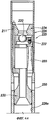
На фиг.2 приведено поперечное сечение варианта осуществления, показанного на фиг.1, в открытом положении.FIG. 2 is a cross-sectional view of the embodiment shown in FIG. 1 in an open position.
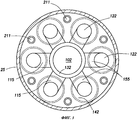
На фиг.3 приведено сечение по линии А-А варианта осуществления, показанного на фиг.3.Figure 3 shows a section along the line aa of the embodiment shown in figure 3.
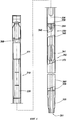
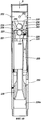
На фиг.4 приведено поперечное сечение предлагаемого узла для сбора обломков, пригодного для использования вариантами осуществления предлагаемой приводной головки.Figure 4 shows a cross section of the proposed site for the collection of debris, suitable for use by embodiments of the proposed drive head.
На фиг.5 приведено поперечное сечение альтернативного варианта осуществления предлагаемой приводной головки в закрытом положении.Figure 5 shows a cross section of an alternative embodiment of the proposed drive head in the closed position.
На фиг.6А приведено поперечное сечение приводной головки, показанной на фиг.5, в открытом положении.On figa shows a cross section of the drive head shown in figure 5, in the open position.
На фиг.6В приведено сходное поперечное сечение альтернативного варианта осуществления приводной головки, показанной на фиг.6А, в закрытом положении.FIG. 6B shows a similar cross section of an alternative embodiment of the drive head shown in FIG. 6A in the closed position.
На фиг.7 приведено поперечное сечение альтернативного варианта осуществления узла для сбора обломков настоящих изобретений.7 is a cross-sectional view of an alternative embodiment of a debris collection unit of the present invention.
На фиг.8 приведено поперечное сечение альтернативного варианта осуществления фильтровального участка узла для сбора обломков показанного на фиг.8.FIG. 8 is a cross-sectional view of an alternative embodiment of a filter section of the debris collection unit shown in FIG.
На фиг.9 приведено перспективное изображение предлагаемой приводной головки в собранном состоянии с узлом для сбора обломков настоящих изобретений.Figure 9 shows a perspective image of the proposed drive head in an assembled state with a node for collecting fragments of the present inventions.
На фиг.10 приведено поперечное сечение агрегата, показанного на фиг.9.Figure 10 shows the cross section of the unit shown in figure 9.
На фиг.11 приведено поперечное сечение фильтровального участка агрегата, показанного на фиг.9.In Fig.11 shows a cross section of the filter section of the unit shown in Fig.9.
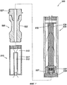
На фиг.12а и 12b приведены поперечные сечения вариантов осуществления участка для удаления обломков агрегата, показанного на фиг.9.On figa and 12b shows the cross-section of embodiments of a plot for removing fragments of the unit shown in Fig.9.
На фиг.13 приведено поперечное сечение клапана на фильтровальном участке настоящих изобретений.13 is a cross-sectional view of a valve in a filter section of the present invention.
Осуществление изобретенияThe implementation of the invention
Приведенные здесь подробности служат лишь в качестве примеров для более наглядного представления предпочтительных вариантов осуществления настоящих изобретений в том случае, когда считают их самыми пригодными для понятного изложения принципов и концептуальных аспектов различных вариантов осуществления настоящих изобретений. В этом отношении не делали попыток показать структурные особенности изобретений более подробно, чем требуется для самой сути изобретений, причем описание ведется со ссылкой на чертежи, дающие представление сведущим в данной области, как можно использовать на практике различные формы этих изобретений.The details given here serve only as examples to more clearly present the preferred embodiments of the present inventions when they are considered most suitable for a clear presentation of the principles and conceptual aspects of the various embodiments of the present inventions. In this regard, no attempt was made to show the structural features of the inventions in more detail than is required for the essence of the inventions, moreover, the description is made with reference to the drawings, giving knowledge to those skilled in the art how various forms of these inventions can be used in practice.
Следующие определения и пояснения не предполагается менять в какой-либо будущей конструкции, если только они не будут явно и однозначно изменены в следующем описании. В тех случаях, когда толкование термина сделало бы его бессмысленным или почти бессмысленным, следует взять определение из Webster Dictionary, 3rd Edition. Нельзя использовать определения и/или толкования из других заявок на патент, патентов или публикаций, имеющих или не имеющих отношения к этим изобретениям, если только это не будет специально оговорено или если необходимо их использовать для отстаивания действительности.The following definitions and explanations are not intended to be changed in any future design, unless they are explicitly and unambiguously changed in the following description. In cases where the interpretation of the term would make it meaningless or almost meaningless, we should take the definition from the Webster Dictionary, 3 rd Edition. Definitions and / or interpretations from other patent applications, patents or publications that are or are not related to these inventions should not be used, unless this is expressly agreed upon or if it is necessary to use them to uphold reality.
Используемый здесь термин "прикрепленный" или его сочетание описывает и относится, по меньшей мере, к частичному соединению двух объектов.As used herein, the term “attached” or a combination thereof describes and refers to at least a partial connection of two objects.
Используемый здесь термин "неотъемлемый" обозначает и относится к отсутствию ничего существенного после сборки.As used herein, the term “inherent” means and refers to the absence of anything significant after assembly.
Используемый здесь термин "флюид" обозначает сплошное аморфное вещество, молекулы которого свободно движутся друг за другом. Оно склонно принимать форму сосуда, в котором оно находится, и представляет собой, например, жидкость или газ.As used herein, the term "fluid" means a continuous amorphous substance, the molecules of which freely move one after another. It tends to take the form of the vessel in which it is located and is, for example, a liquid or gas.
В отличие от действительных примеров и тех случаев, когда указано иное, все численные значения, выражающие количество используемых здесь компонентов, следует воспринимать во всех случаях измененными путем добавления "примерно".Unlike actual examples and those cases where otherwise indicated, all numerical values expressing the number of components used here should be taken in all cases as modified by adding "approximately".
Используемый здесь термин "подъемная колонна" обозначает устройство, имеющее обычно сопло с входным отверстием для поступления флюида сквозь это устройство в выпускное отверстие и для создания разрежения, обеспечивающего всасывание флюида через всасывающее отверстие и смешение с флюидом, протекающим между входным и выходным отверстиями. Подъемные колонны содержат, например, струйные насосы и насосы Вентури. Термин "ось подъемной колонны" обозначает центральную ось сопла.As used herein, the term "riser column" means a device that typically has a nozzle with an inlet for fluid to flow through the device into the outlet and to create a vacuum that sucks the fluid through the suction port and mixes with the fluid flowing between the inlet and outlet ports. Lifting columns include, for example, jet pumps and venturi pumps. The term "axis of the lifting column" refers to the central axis of the nozzle.
Используемый здесь термин "уловитель обломков" обозначает устройство для отделения твердых тел от скважинных флюидов, которое содержит сетчатые фильтры и корзиночные уловители.As used herein, the term "debris trap" refers to a device for separating solids from wellbore fluids that includes strainers and basket traps.
Различные варианты осуществления настоящих изобретений предусматривают создание приводной головки, создающей повышенное дифференциальное давление. В других вариантах осуществления приводную головку, создающую дифференциальное давление, можно использовать с целым рядом вспомогательных буровых устройств и/или модульных вспомогательных буровых устройств. В одном варианте осуществления приводная головка, создающая дифференциальное давление настоящих изобретений объединена с прибором для гидравлической очистки ствола скважины, таким как ловильный паук или противопесочный фильтр, но не только с ними. Дифференциальное давление создается за счет обратной циркуляции потока со стороны внутреннего диаметра приспособления и/или добычной трубы, а не под действием потока со стороны наружного диаметра добычной трубы и/или ствола скважины или обсадной колонны. Этот поток создается, по меньшей мере частично, за счет перепада давлений и эффекта Вентури. Различные варианты осуществления настоящих изобретений максимизируют давление, оказываемое из подъемной колонны через внутреннюю трубу.Various embodiments of the present invention provide for the creation of a drive head that creates an increased differential pressure. In other embodiments, a differential pressure driving head can be used with a variety of auxiliary drilling devices and / or modular auxiliary drilling devices. In one embodiment, the differential pressure drive head of the present invention is combined with, but not limited to, a hydraulic wellbore cleaner, such as a fishing spider or a sand filter. Differential pressure is created due to the reverse circulation of the flow from the side of the inner diameter of the device and / or production pipe, and not under the action of the flow from the side of the external diameter of the production pipe and / or borehole or casing. This flow is created, at least in part, due to the pressure drop and the Venturi effect. Various embodiments of the present invention maximize the pressure exerted from the lifting column through the inner tube.
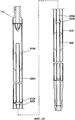
Обращаясь теперь к чертежам, где на нескольких фигурах используются одинаковые условные обозначения, на фиг.1-3 показан вариант осуществления предлагаемой приводной головки 110, расположенной в стволе скважины 105. На фиг.1 приводная головка 110 изображена в закрытом положении, а на фиг.2 она изображена в открытом положении. Альтернативные варианты осуществления приводной головки 110 способны включать и другие участки или сегменты, которые могут потребоваться для конкретной схемы бурения или конкретной процедуры бурения. В некоторых вариантах осуществления подсоединены еще и переводники или части бурильной колонны, такие как верхний переводник (пример которого показан на фиг.4).Turning now to the drawings, where the same reference characters are used in several figures, Figs. 1-3 show an embodiment of the proposed
В некоторых вариантах осуществления приводная головка 110 содержит трубчатый элемент 25, который создает вытянутый в осевом направлении проток 102 и отводные отверстия 150 в стенках трубчатого элемента 25. Трубчатый элемент 25 имеет на своих концах средства, такие как резьба, для проточного соединения приводной головки с насосно-компрессорной колонной. Приводная головка 110 дополнительно содержит клапанный блок 30, расположенный в трубчатом элементе 25 так, чтобы он мог перемещаться внутри него в осевом направлении, переходя то в открытое, то в закрытое положение. В общем, когда он находится в закрытом положении, то отводные отверстия 150 перекрыты, и прекращается сообщение между внутренней областью приводной головки и кольцевым пространством вокруг насосно-компрессорной колонны в стволе скважины 105. В открытом положении отводные отверстия 150 открыты.In some embodiments, the
Корпус клапанного блока 30 содержит верхний элемент 142, по меньшей мере, одну подъемную колонну 155 и отражающее основание 175. Клапанный блок 30 имеет сферическое клапанное седло 132 для шарового заторного органа, окружающее вытянутый в осевом направлении перепускной канал 156. Следует отметить, что клапанное седло 132 находится за линией обводного канала 115 и перед всасывающей камерой 124. В верхний элемент 142 съемно (на резьбе) вставлены струйные сопла 122 подъемной колонны, причем подъемные трубы 155 проходят соосно со струйными соплами 122 подъемной колонны. Открытое пространство под соплами образует всасывающую камеру 124. В предпочтительном варианте осуществления имеется шесть подъемных колонн, но достаточно и одной подъемной колонны, чтобы обеспечить работу приводной головки. Как показано на чертежах, подъемные колонны используют не один лишь обтекаемый конфузорный профиль, и в предпочтительном варианте осуществления конфузорный профиль сочетается с обтекаемым диффузорным профилем. Эти профили вполне подходят для скважинных флюидов, содержащих твердые частицы. Отражающее основание 175 имеет проходящий в осевом направлении проточный канал 162 для флюида и коническую верхнюю поверхность 164. Отражающее основание установлено так, чтобы оно могло скользить или перемещаться в трубчатом элементе 25 в осевом направлении вместе с верхним элементом 142. На фиг.1 отражающее основание 175 показано в закрытом положении с перекрытыми отводными отверстиями 150 и с перекрытыми проточными подъемными трубами 155. На отражающем основании 175 установлена пара смещенных относительно друг друга в осевом направлении уплотнений 158, чтобы они могли, упираясь во внутреннюю стенку трубчатого элемента 25, изолировать отводные отверстия 150 от протока 102 для флюида. В некоторых вариантах осуществления, по меньшей мере, часть струйных сопел 122 подъемной колонны снабжена покрытием.The
Подъемные трубы 155 зажаты между верхним элементом 142 и отражающим основанием 175 болтами 211 (показанными на фиг.3), проходящими между основанием и верхним элементом. В этом варианте осуществления подъемные трубы легко снимать для проведения технического обслуживания и текущего ремонта. Кроме того, приводную головку можно изготовлять по техническим условиям заказчика, меняя длину и форму подъемных колонн и сопел. Агрегат, состоящий из верхнего элемента 142, подъемных труб 155 и отражающего основания 175, можно устанавливать на место в трубчатый элемент 25 в закрытом или открытом положении с помощью срезных штифтов 176, фиксаторов (не показанных на чертежах) или других аналогичных приспособлений. В некоторых вариантах осуществления клапанный блок 30 устанавливают в трубчатый элемент 25 путем посадки с натягом.Lifting
Линии обводных каналов 115 могут, в общем, быть ориентированы в направлении от внутреннего протока 102 к струйным соплам 122 подъемной колонны. В одном варианте осуществления обводной канал 115 открыт к протоку для флюида под углом примерно девяноста (90) градусов. В альтернативном варианте осуществления обводные каналы открыты от протока для флюида под углом примерно 120 градусов. В другом альтернативном варианте осуществления обводной канал открыт к протоку для флюида под углом примерно 135 градусов. Еще в одном альтернативном варианте осуществления обводной канал открыт к протоку для флюида под углом примерно 150 градусов. Еще в одном альтернативном варианте осуществления обводной канал открыт к протоку для флюида под углом менее чем примерно 150 градусов. В общем, допустим любой угол, не слишком препятствующий протеканию флюида.The lines of the
Клапанное седло 132 предназначено для посадки шарового или шарообразного запорного органа 120 (показанного на фиг.2). В некоторых вариантах осуществления шарообразный запорный орган 120 высвобождается из устья скважины над приводной головкой 110 и попадает в проточный канал, а затем во внутренний осевой перепускной канал 156. Понятно, что можно использовать и запорные органы другой формы, лишь бы запорный орган прилегал к седлу настолько плотно, чтобы прервать поступление флюида через седло. Обычно шаровой запорный орган 120 отходит от его поверхности или лишь касается поверхности. Но в некоторых вариантах осуществления настоящих изобретений можно использовать и другие механизмы, пригодные для удержания и/или отсоединения шарового запорного органа 120, такие как полка или выступ над седлом клапана 132. При посадке на клапанное седло 132 шарового запорного органа 120 поступление флюида 147 через осевой перепускной канал 156 прекращается, и флюид нагнетается по насосно-компрессорной колонне в приводную головку 110, которая отводит его в линии обводных каналов 115 и через струйные сопла 122 подъемной колонны. В некоторых других вариантах осуществления срезной штифт 176 удерживает приводную головку либо в закрытом, либо в открытом положении. В общем, в закрытом положении отсутствует сообщение между внутренней частью приводной головки и кольцевым зазором в стволе скважины 105.The
Как было указано, когда шаровой запорный орган 120 садится на клапанное седло 132, прекращается поступление скважинного флюида в насосно-компрессорную колонну из осевого перепускного канала 156. При нарастании давления во флюиде клапанный блок 30 срезает штифты 176 и перемещается или выдавливается вниз в открытое положение, показанное на фиг.2. При этом отражающее основание 175 опускается ниже отводных отверстий 150 и обеспечивает слив из подъемной колонны в кольцевое пространство трубчатого элемента 25.As indicated, when the
В открытом положении скважинный флюид отводится в струйные сопла 122 подъемной колонны и выпускается через них. В некоторых вариантах осуществления подъемные трубы 155 и струйные сопла 122 подъемной колонны могут иметь различную форму, объем и/или длину. Скважинные флюиды, протекающие через струйные сопла 122 подъемной колонны, снабжают подъемные колонны энергией, обеспечивающей увеличение скорости и понижение давления в протекающем скважинном флюиде. В результате во всасывающей камере 124 создается парциальное давление. Скважинный флюид проходит через всасывающую камеру, увлекая флюиды во всасывающую камеру. За счет трения между скважинными флюидами во всасывающей камере создается разрежение. За счет понижения давления всасывающая камера «засасывает» или втягивает дополнительное количество флюида с участка проточного канала 162 под шаровым клапаном 120. Прохождение сжатого флюида через струйные сопла 122 подъемной колонны во всасывающую камеру 124 и через подъемные трубы 155 обеспечивает всасывание во всасывающую камеру (эффект Вентури), так что любой скважинный флюид в подъемной колонне ниже приводной головки будет втягиваться во всасывающую камеру по проточному каналу 162, а оттуда - в подъемные трубы 155 вместе флюидом из струйных сопел 122 подъемной колонны. Затем смесь поступает во флюидный проток или проточный канал 109 через гладкостенный расширяющийся раструб подъемных колонн, где кинетическая энергия флюида снова превращается в потенциальную энергию, приводя к повышению давления. Затем смешанный флюид выходит из подъемной колонны и поступает в ствол скважины по протоку 112.In the open position, the downhole fluid is discharged into and discharged through the
В некоторых вариантах осуществления имеется одна или несколько подъемных колонн, расположенных по окружности вокруг проточного канала 162. В альтернативных вариантах осуществления имеется множество подъемных колонн, расположенных в радиальном направлении симметрично вокруг проточного канала 162. В одном варианте осуществления имеются, по меньшей мере, две (2) подъемные колонны вокруг проточного канала 162. В альтернативном варианте осуществления имеются, по меньшей мере, три (3) подъемные колонны, расположенные по окружности вокруг проточного канала 162. Еще в одном альтернативном варианте осуществления имеются, по меньшей мере, четыре (4) подъемные колонны, расположенные вокруг проточного канала 162. В другом альтернативном варианте осуществления имеются, по меньшей мере, пять (5) подъемных колонн, расположенных вокруг проточного канала 162. Еще в одном альтернативном варианте осуществления имеются, по меньшей мере, шесть (6) сопел, расположенных вокруг проточного канала 162. В другом альтернативном варианте осуществления имеются, по меньшей мере, семь (7) подъемных колонн, расположенных вокруг проточного канала 162. Еще в одном альтернативном варианте осуществления имеются, по меньшей мере, восемь (8) подъемных колонн, расположенных вокруг проточного канала 162. В общем, можно использовать любое количество подъемных колонн, чтобы оптимизировать эффект разрежения, и/или эффект подъемной колонны, и/или эффект, оказываемый перепадом давления.In some embodiments, there is one or more lifting columns circumferentially around the
В общем, по методу эксплуатации и согласно фиг.1 буровой раствор поступает через приводную головку 110 по флюидному протоку 102. Когда приводную головку 110 находится в закрытом положении, буровой раствор поступает из протока 102 по проточному каналу 162 на буровую коронку или фрезер в нижней части колонны. При проведении фрезерования или в том случае, когда нужно удалить осколки и/или обломки, шаровой запорный орган 120 опускают на клапанное седло 132 (как показано на фиг.2). Продолжающееся нагнетание бурового раствора приводит к повышению давления в трубчатом элементе 25, заставляя его клапанный блок 30 перемещаться вниз до тех пор, пока сливное отверстие подъемной колонны не совпадет с отводным отверстием 150, позволяя тем самым буровому раствору поступать кольцевое пространство ствола скважины за счет перенаправления флюида из протока 102 в проток 112. Как было описано, поток, вытекающий через струйные сопла 122 подъемной колонны и подъемные трубы 155, заставляет флюиды подниматься по насосно-компрессорной колонне из-под приводной головки 110 по протоку 102 во всасывающую камеру 124.In general, according to the method of operation and FIG. 1, the drilling fluid enters through the
В некоторых вариантах осуществления подъемные трубы 155 имеют конусообразную форму. В некоторых вариантах осуществления можно индуцировать поток за счет циркуляции и/или рециркуляции. В одном варианте осуществления подъемные трубы 155 являются расширяющимися, чтобы можно было создавать поток бурового раствора. В альтернативном варианте осуществления подъемные трубы являются сужающимися, чтобы можно было создавать поток бурового раствора. В другом альтернативном варианте осуществления подъемные трубы 155 имеют сужающиеся и расширяющиеся поверхности, чтобы можно было создавать поток бурового раствора. Еще в одном альтернативном варианте осуществления подъемные трубы 155 содержат множество участков с расширяющимся и сужающимся потоком, чтобы можно было создавать поток бурового раствора. В общем, в варианте осуществления настоящих изобретений можно использовать участки перемежающегося сужения и расширения.In some embodiments, the
В некоторых вариантах осуществления проточный канал 109 бурового раствора, направленный вдоль оси подъемной колонны через подъемные трубы 155, проходит почти параллельно протоку 102. В некоторых альтернативных вариантах осуществления поток бурового раствора через подъемные трубы поступает почти параллельно протоку 102. В общем, проточный канал 109 бурового раствора, поступающего через подъемные трубы 155, в отношении направления течения коорлинирована с протоком 102.In some embodiments, the
По меньшей мере, часть перенаправленного бурового раствора поступает под высоким давлением по проточному каналу 109 и обычно понижает давление при прохождении через всасывающую камеру 124 в проточный канал 109. В общем, давление в проточном канале согласно настоящим изобретениям зависит от вместимости и/или площади поверхности проточного канала. В общем, перепад давления, создаваемый в разных вариантах осуществления настоящих изобретений, можно использовать для подъема обломков и/или осколков и/или других предметов.At least a portion of the redirected drilling fluid flows at high pressure through the
На фиг.3 приведено сечение варианта осуществления, показанного на фиг.2 по линии 3-3. Вокруг протока 102 можно видеть множество болтов 211, сопел 122 и подъемных труб 155.Figure 3 shows a cross section of the embodiment shown in figure 2 along line 3-3. Around
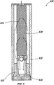
На фиг.4 показан вариант осуществления узла для сбора обломков 330, используемого с предлагаемой приводной головкой и содержащего сепараторный элемент 340, трубчатую сборную камеру или корзину 360 и нижний переводник (или патрубок) 335, навинченный на нижнюю часть корзины 360. В сборной камере или корзине 360 находится съемный субблок 362, содержащий установочную плиту или основание 336, вторую или внутреннюю трубу 372 и стабилизаторы 341. Съемный субблок 362 защемлен между нижним переводником 335 и корзиной 360. Внутренняя труба 372 имеет отверстие 345 на своем верхнем конце, через которое флюид поступает в камеру 360. Внутренняя труба 372 преимущественно имеет открытый конец, но может иметь и другую конфигурацию, такую как множество отверстий вокруг верхнего конца внутренней трубы. Согласно настоящим изобретениям нижний переводник можно отсоединять и снимать трубный блок 362, чтобы вымыть струей воды обломки, скопившиеся в корзине 360.Figure 4 shows an embodiment of a unit for collecting
Первая камера 338 и проволочная коробка 339 образуют верхний блок 310 и расположены над вторым или внутренне-трубным блоком 362. Другие варианты осуществления включают трубчатый переход 368 и/или удлинительный участок 371. Когда приводная головка находится в открытом положении (в режиме рециркуляции), флюид поднимается в узел для сбора обломков 330 по флюидному каналу 301 и поступает во внутреннюю трубу 372. Обычно буровой раствор, поступающий во внутреннюю трубу 372, несет обломки и/или осколки, которые нужно отделить от бурового раствора. Буровой раствор поднимается во вторую внутреннюю трубу 372 и проходит сквозь сепараторный элемент 340. Сепараторный элемент 340 заставляет более крупные обломки и/или осколки погружаться в сборную камеру или корзину 360. Флюид и более мелкие обломки проходят сквозь отверстия или проходы 364 в сепараторном элементе 340. В одном варианте осуществления узла для сбора обломков 330, предназначенного для использования при фрезеровании, узел для сбора обломков 330 можно удлинить или умножить в зависимости от длины корпуса, в котором должна выполняться скважинно-стволовая операция.The
Буровой раствор будет продолжать подниматься через узел для сбора обломков 330 по флюидному каналу 306 в предлагаемую приводную головку. В некоторых вариантах осуществления буровой раствор проходит сквозь проволочную коробку 339, чтобы еще более освободиться от обломков и/или осколков. В других вариантах осуществления, по меньшей мере, часть очищенного бурового раствора возвращается обратно в ствол скважины для проведения бурильных операций.The drilling fluid will continue to rise through the
На фиг.5 и 6А показан альтернативный вариант осуществления приводной головки 225, содержащей корпус 226 с установленным в нем клапанным блоком 228. Корпус 226 содержит кольцевой выступ 226b, участок 226а уменьшенного внутреннего диаметра и отводные отверстия 250 в нем. Клапанный блок 228 содержит трехсоставной верхний элемент 234, подъемные колонны 255 и основной отражатель 230, скрепленные болтами 211. Верхний элемент 234 содержит шариковую направляющую 234а, клапанную плиту 234b и стабилизатор подъемной колонны 234c. Шариковая направляющая 234а содержит клапанное седло 232 и установленные сопла 222 подъемной колонны. Когда приводная головка переходит в открытое положение, показанное на фиг.6А, выступ 236 на отражателе 230 входит в зацепление с участком уменьшенного внутреннего диаметра 226а, чтобы надлежащим образом выровнять клапанный блок 228 с отводными отверстиями 250.Figures 5 and 6A show an alternative embodiment of a
На фиг.6B показан альтернативный вариант осуществления приводной головки 225 во включенном состоянии. В этом варианте осуществления в корпусе 226 над клапанным блоком 338 установлен второй клапанный блок 250, и в стенке корпуса 226 образованы перепускные отверстия 252. Клапанный блок 250 содержит корпус клапана 254 и кольцевые уплотнения 256, упирающиеся во внутреннюю стенку корпуса 226. На корпусе 224 вокруг осевого канала 260 образовано седло клапана 258. Седло имеет такой размер и форму, чтобы образовался клапанный элемент, в показанном варианте осуществления - шаровой клапанный элемент 262. Осевой канал 260 имеет такой размер и форму, чтобы шаровой запорный орган 220 мог проходить сквозь него. Корпус 254 установлен внутри корпуса 226 таким образом, чтобы он мог совершать возвратно-поступательное перемещение в осевом направлении по стрелке D. При эксплуатации второй клапанный блок можно помещать в скважину в рабочем положении (не показанном на чертеже), т.е. с клапанным корпусом 254, поднятым в положение, закрывающее перепускные отверстия 252. Можно использовать срезной штифт или другое приспособление, чтобы удерживать клапанный корпус 254 в поднятом положении. Если необходимо прекратить поступление раствора через приводную головку 225 и открыть перепускные отверстия 252, прижимают большой запорный орган (шаровой запорный орган 264) к седлу 258 и опускают клапанный корпус 254 вниз во включенное положение, показанное на фиг.6B. Клапанный блок 250 можно использовать для подачи скважинных флюидов в насосно-компрессорную колонну либо из насосно-компрессорной колонны через перепускные отверстия 252. Клапанный блок 250 позволяет опускать приводную головку 225 в скважину в открытом состоянии, а затем отключать ее в результате срабатывания клапанного блока 250.6B shows an alternative embodiment of the
На фиг.7 приведено частичное сечение альтернативного варианта осуществления модульного аппарата для сбора обломков 500 с запорным клапаном 532, пригодного для использования некоторых вариантов осуществления настоящего изобретения. В общем, для удаления из бурового раствора более крупных обломков используется первый участок для сбора обломков 510, содержащий внутреннюю трубу 512 и расширенный участок 515. При подъеме бурового раствора внутренняя труба 512 расширяется на участке 515 и выпускает порцию накопившихся обломков в отстойную камеру 517.FIG. 7 is a partial sectional view of an alternative embodiment of a modular
Со временем отстойная камера 517 наполняется, и ее приходится чистить. В некоторых вариантах осуществления настоящего изобретения используют переводник вертлюга 520 с выемкой 522 для захвата имеющимися клещами и/или инструментами на буровой площадке. Сам по себе переводник 520 можно отсоединить от бурильной колонны, снять отстойную камеру 517 и опорожнить ее, тем самым обеспечивая экономию драгоценного времени проходки.Over time, the settling
К некоторым вариантам осуществления настоящего изобретения можно прикреплять уникальный пескоуловитель 530, предназначенный для удаления зернистого материала, такого как песок и расклинивающий наполнитель, но не только их, чтобы можно было интенсифицировать очистку скважин. Пескоуловитель 530 обычно содержит сетку 539, внутреннюю трубу 572, камеру для сбора обломков 537, опорную плиту 534 и запорный клапан 532. Запорный клапан 532 может иметь такую конструкцию, чтобы он открывался в случае противотока и закрывался в случае прямотока. В некоторых других вариантах осуществления имеются отверстия (не показанные на чертежах), позволяющие проводить работу при нормальной циркуляции.A
На фиг.8 изображен альтернативный запорный клапан, пригодный для использования с разными вариантами осуществления предлагаемого пескоуловителя 630, содержащего удлиненную камеру для сбора обломков 637, запорный клапан 632, сетку 639, внутреннюю трубу 672 и опорную плиту 634. В общем, выбирают такой флюид, чтобы в режиме прямотока и/или противотока он обтекал запорный клапан 632.Fig. 8 shows an alternative shutoff valve suitable for use with various embodiments of the proposed
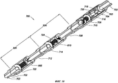
На фиг.9 и 10 показан другой альтернативный вариант осуществления предлагаемого блока для сбора обломков 700 на насосно-компрессорной колонне 702 (представляющей собой бурильную колонну). Насосно-компрессорная колонна 702 имеет внутренний проточный канал 703, сообщающийся с блоком для сбора обломков. Блок для сбора обломков 700 содержит: блок приводной головки 704, сетчатый фильтр бурильной трубы 706, верхний манипуляционный переводник 708, сеточный блок 800, нижний манипуляционный переводник 712 и сепараторный блок 900. Чтобы совмещать резьбы и перекрывать нижнюю часть блоков, включены патрубки 710, 714 и 722. В случае показанной конфигурации блок 700 содержит, например, лишь по одному из каждых компонентов. Но в случае необходимости можно установить последовательно не одну сепараторную перегородку. Следует отметить, что манипуляционные переводники имеют одну и ту же конфигурацию (размер и форму), чтобы бурильные трубы, снабженные секциями блока 700, можно было захватывать и обрабатывать одними и теми же клещами и/или инструментами на буровой установке или установке для ремонта скважин. Манипуляционные переводники имеют такую длину, чтобы в собранном виде с одним из фильтров или сепараторных блоков их можно было обрабатывать как секцию бурильной трубы. Например, общую длину манипуляционного переводника 712 подбирают таким образом, чтобы после соединения с сепараторным блоком 900 и патрубком 722 плеть имела длину примерно 9 м, чтобы можно было ее обрабатывать на буровой установке или извлекать из скважины, размещать на буровой установке и демонтировать и опорожнять без скручивания бурового оборудования. Аналогичным образом общую длину манипуляционного переводника 708 выбирают таким образом, чтобы после прикрепления к блоку фильтрующего экрана 724 и патрубка 722 плеть имела длину примерно 9 м и чтобы можно было ее обрабатывать как единую плеть трубы. То же самое относится к длине сборки с приводной головкой 704 и экраном бурильной трубы 706. Блок для сбора обломков 700 может иметь длину 27,5 м, что позволяет ее обрабатывать как три плети бурильных труб.Figures 9 and 10 show another alternative embodiment of the proposed unit for collecting
Приводная головка 704 может иметь любую из описанных здесь конфигураций. Приводная головка 704 соединена с плетью бурильной трубы 702 и ее проточным каналом 703. Выпускные каналы 716 открываются при посадке запорного шарового органа 718 на седло в приводной головке 704. Запорный шаровой орган 718 отводит также поток из бурильной трубы 702 через подъемные колонны 720 и выпускные каналы 716 в кольцевое пространство, образованное между блоком для сбора обломков 700 и стенкой ствола скважины. Подъемные колонны 720 создают зону разрежения, которая, в свою очередь, заставляет скважинные флюиды стекать в нижнюю часть бурильной трубы 702 и подниматься по проточному каналу 703 через сепараторный блок 900 и сеточный блок 800. Обломки удаляются из скважинного флюида в сепараторном блоке 900 и сеточном блоке 800.
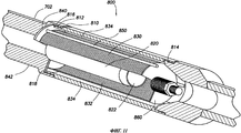
На фиг.11 и 13 показано устройство сеточного блока 800. Сеточный блок 800 содержит цилиндрический корпус 810, снабженный наружной резьбой на нижнем конце 812 для соединения с нижним манипуляционным переводником 712 и внутренней резьбой на верхнем конце 814 для соединения с верхним манипуляционным переводником 708. В этом варианте осуществления отсутствует патрубок 714, показанный на фиг.10. Основание 840 установлено на нижнем конце сеточного блока 800 и защемлено между противоположными кольцевыми выступами 816 и 818. Основание 840 имеет форму плоской шайбы с центральным проточным каналом 842 по центру. На основании 840 установлена внутренняя скоростная труба 820, отходящая от основания 840 в осевом направлении. Внутренняя скоростная труба 820 имеет цилиндрическую форму и такой размер, чтобы она соответствовала периметру центрального проточного канала 842. Верхний конец 822 скоростной трубы 820 открыт.11 and 13, the device of the
Цилиндрическая сетка 830 отходит от основания 840 и создает кольцевое пространство 832 вокруг внутренней скоростной трубы 820. В настоящем варианте осуществления сетка 830 представляет собой каркасно-проволочный фильтр, но очевидно, что можно использовать и другие фильтры для отделения обломков. Между корпусом 810 и сеткой 830 образовано второе кольцевое пространство 834. Верхний конец цилиндрической сетки 830 накрыт колпаком 860. Для создания опоры снаружи к сетке 830 прикреплено множество проходящих в осевом направлении распорок 850.The
На колпаке 860 установлен предохранительный клапан 870. Устройство этого предохранительного клапана 870 показано на фиг.13. Предохранительный клапан 870 содержит запорный орган 872, шток клапана 874, пружину сжатия 876 и клетку клапана 878. Как показано на чертеже, пружина 876 прижимает запорный орган 872 к колпаку 860, закрывая верхнюю часть фильтра 830. Когда фильтр 830 забивается обломками, давление флюида внутри фильтра 830 преодолевает сопротивление пружины 876, и клапанный орган 872 отходит от колпака 860, позволяя флюиду миновать фильтр 830. Как показано на чертеже, усилие, прилагаемое пружиной 876 к запорному органу 872, можно регулировать, поворачивая гайку 879 на резьбовом штоке 874.A
В нормальном режиме работы скважинные флюиды, содержащие обломки, поступают в сеточный блок 800 по трубе 820. Поток, поступающий в кольцевое пространство 832, подвергается фильтрованию, проходя через сетку 830 в кольцевое пространство 834. При фильтровании скважинных флюидов обломки скапливаются в кольцевом пространстве 832, а профильтрованный поток выходит из сеточного блока 800 через верхний манипуляционный переводник 708. Согласно настоящему изобретению, когда нижний манипуляционный переводник 712 (патрубок 714) отсоединен от корпуса 810, агрегат, состоящий из основания 840, трубы 820 и сетки 830, можно извлечь в осевом направлении из корпуса 810 и подвергнуть его чистке или ремонту.In normal operation, borehole fluids containing debris enter the
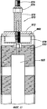
На фиг.12а и 12b показано устройство сепараторного блока 900. Сепараторный блок 900 содержит цилиндрический корпус 910, который снабжен наружной резьбой на нижнем конце 912 и внутренней резьбой на верхнем конце 914. К основанию 930 прикреплена внутренняя скоростная труба 920, проходящая в осевом направлении. Труба 920 создает кольцевое пространство 926 для сблора обломков внутри корпуса 910. Основание 930 установлено между противоположными выступами на корпусе 910 и патрубком 722. Снаружи трубы 920 установлены стабилизаторы 922, чтобы можно было центрировать ее внутри корпуса 910. Над открытым концом 924 трубы 920 установлен пористый отражательный конус (или «отбойник») 940. Проточный канал 932 сообщается с внутренней областью трубы 920. При эксплуатации скважинные флюиды поступают в сепараторный блок 900 или выпускаются из скоростной трубы 920 в направлении отражательного конуса 940, где более крупные обломки отклоняются в радиальном направлении и попадают в кольцевое пространство 926. Сепараторный блок 900 легко можно извлечь, отвинчивая патрубок 722.12a and 12b illustrate the arrangement of a
Согласно особенностям настоящего изобретения сеточный и сепараторный блоки могут размещаться в длину друг за другом, или можно использовать множество блоков в сочетании друг с другом, в зависимости от конкретных условий на буровой площадке. Если ожидается увеличение количества обломков, тогда можно нарастить сепараторную секцию в длину. Как показано на фиг.12b, корпус 910 использует наружные резьбы 910а, чтобы нарастить вторую секцию 910b. К трубе 920 добавлена скоростная труба 920d с помощью двух втулок 920а и 920c и сортировочная секция трубы 920b. Подобным образом к сепараторному блоку 900 можно добавить одну или несколько секций, чтобы можно было накапливать больше обломков. В случае необходимости аналогичным образом можно наращивать сеточный блок 800.According to the features of the present invention, the grid and separator blocks can be placed in length one after another, or many blocks can be used in combination with each other, depending on the specific conditions at the drilling site. If an increase in the amount of debris is expected, then the separator section can be extended in length. As shown in FIG. 12b, the
При эксплуатации можно присоединять и отсоединять патрубки для разных блоков на буровой установке, такой как стеллаж для труб, с помощью ручного инструмента с силовым приводом, такого как цепной трубный ключ и трубные клещи или горизонтального приспособления для навинчивания. Например, при сборке или разборке сепараторного приспособления 900 патрубок 722 прикрепляют или снимают с помощью ручного инструмента с силовым приводом, не используя напольное оборудование буровой установки. Например, при разборке сепараторного приспособления с целью его чистки можно ослабить (или компенсировать) крутящий момент докрепления патрубка, поскольку приспособление извлекают из скважины (или опускают в скважину) с помощью приводного трубного ключа на полу буровой вышки, а патрубок снимают и чистят сепараторное приспособление на стеллаже для труб. То же самое относится и к патрубку 714 и фильтровальному блоку 800. После помещения разных приспособлений в бурильную колонну и опускания в ствол скважины эти приспособления используют таким образом, как было описано выше. После извлечения приспособлений из ствола скважины их отсоединяют или открепляют от бурильной колонны с помощью буровой установки. Как было указано выше, блоки имеют такую конструкцию, чтобы их можно было удалять из скважины в виде плети. Сборку, содержащую патрубок 722, сепараторный блок 900 и манипуляционный переводник 712 удаляют из колонны в виде единого целого. Затем эту сборку можно отнести от буровой установки, поместив, например, на стеллаж для труб, чтобы освободить буровую установку для других нужд. Затем снимают патрубок 722 с помощью ручных инструментов с силовым приводом, а не бурового оборудования. Съемные лицевые панели, внутренняя труба и стабилизаторы теперь легко поддаются чистке. Аналогичным образом фильтровально-проволочный блок и приводную головку можно отсоединить от бурильной колонны, перенести на стеллаж для труб или в другое место, а затем разобрать и провести чистку. Термины «патрубок» и «нижний переводник» используются здесь, чтобы указать тот участок трубы, где имеются проточный канал, причем труба прикреплена к концу корпуса, например патрубки 714 и 722 и нижний переводник 301.During operation, you can attach and disconnect nozzles for different units on a rig, such as a pipe rack, using power-operated hand tools such as a chain pipe wrench and pipe clamps or horizontal screwdrivers. For example, when assembling or disassembling the
Хотя и было приведено описание конкретных вариантов осуществления изобретений, для сведущих в данной области очевидны многочисленные изменения и альтернативные варианты осуществления. Соответственно, предполагается, что изобретения ограничиваются лишь приведенной формулой.Although specific embodiments of the inventions have been described, numerous changes and alternative embodiments are apparent to those skilled in the art. Accordingly, it is intended that the invention be limited only by the following claims.
Изобретения можно реализовать в других конкретных формах, не отклоняясь от сути настоящих изобретений, поскольку приведенные примеры служат лишь для наглядного представления, но не для ограничения объема. Следовательно, объем изобретения определяется приведенной формулой, а не его описанием. Все изменения в формуле, не выходящие за рамки сущности и эквивалентности терминов, считаются охваченными формулой. Все упоминавшиеся опубликованные документы, патенты и заявки включены сюда целиком путем ссылки на них.The invention can be implemented in other specific forms, without deviating from the essence of the present inventions, since the above examples are only for illustrative purposes, but not to limit the scope. Therefore, the scope of the invention is determined by the above formula, and not its description. All changes to the formula that do not go beyond the essence and equivalence of terms are considered to be covered by the formula. All references to published documents, patents and applications are hereby incorporated by reference in their entirety.
Claims (13)
приводную головку, прикрепленную к насосно-компрессорной колонне для размещения в стволе скважины, причем приводная головка служит для создания противотока в стволе скважины;
сепараторный блок, прикрепленный к насосно-компрессорной колонне за приводной головкой, причем сепараторный блок содержит корпус, образующий внутренний проточный канал, сепараторный элемент и съемный субблок;
при этом съемный субблок содержит внутреннюю трубу, прикрепленную к лицевой панели и расположенную внутри корпуса, образуя кольцевое пространство между внутренней трубой и корпусом, причем указанная лицевая панель съемным образом прикреплена к корпусу и блокирует флюидный поток из нижнего конца кольцевого пространства между внутренней трубой и корпусом, при этом лицевая панель имеет впускной канал для направления флюида внутрь внутренней трубы, причем внутренняя труба и прикрепленная лицевая панель выполнены с возможностью удаления из корпуса путем разъединения лицевой панели и корпуса;
при этом сепараторный элемент расположен вблизи верхнего конца корпуса и способен направлять обломки, присутствующие в скважинном флюиде, в кольцевое пространство между внутренней трубой и корпусом.1. A device for removing debris from a borehole fluid in a wellbore, comprising:
a drive head attached to the tubing for placement in the wellbore, the drive head being used to create a counterflow in the wellbore;
a separator unit attached to the tubing string behind the drive head, the separator block comprising a housing forming an internal flow channel, a separator element and a removable subunit;
wherein the removable subunit comprises an inner pipe attached to the front panel and located inside the housing, forming an annular space between the inner pipe and the housing, said front panel being removably attached to the housing and blocks fluid flow from the lower end of the annular space between the inner pipe and the housing, wherein the front panel has an inlet channel for directing fluid into the inner pipe, the inner pipe and the attached front panel being removable from the housing by disconnecting the front panel and the housing;
however, the separator element is located near the upper end of the body and is able to direct the debris present in the borehole fluid into the annular space between the inner pipe and the body.
(1) подсоединение сепараторного блока к насосно-компрессорной колонне, содержащего:
(а) корпус, образующий проточный канал;
(б) съемный субблок, имеющий внутреннюю трубу, расположенную внутри корпуса и образующую кольцевое пространство между внутренней трубой и корпусом, и лицевую панель, предназначенную для блокирования флюидного потока из нижнего конца кольцевого пространства между внутренней трубой и корпусом, имеющую впускной канал для направления флюида внутрь внутренней трубы; и
(в) сепараторный элемент, расположенный возле верхнего конца корпуса и предназначенный для направления обломков скважинного флюида в кольцевое пространство между внутренней трубой и корпусом;
(2) подсоединение патрубка к сепараторному блоку;
(3) подсоединение приводной головки к насосно-компрессорной колонне выше сепараторного блока по стволу скважины, причем приводная головка предназначена для создания противотока в стволе скважины;
(4) поступление содержащего обломки флюида в нижний конец сепараторного блока через внутреннюю трубу, минуя сепараторный элемент;
(5) захват обломков из скважинного флюида в кольцевое пространство между внутренней трубой и корпусом сепараторного блока;
(6) извлечение, по меньшей мере, части насосно-компрессорной колонны из ствола скважины;
(7) отсоединение сепараторного блока и патрубка, все еще соединенных друг с другом, из насосно-компрессорной колонны;
(8) удаление съемного блока из сепараторного блока; а затем
(9) удаление обломков из съемного блока.8. A method for removing debris from a borehole fluid in a wellbore, comprising the steps of:
(1) connecting a separator unit to a tubing string comprising:
(a) a housing forming a flow channel;
(b) a removable subunit having an inner pipe located inside the casing and forming an annular space between the inner pipe and the casing, and a front panel designed to block fluid flow from the lower end of the annular space between the inner pipe and the casing, having an inlet channel for directing fluid inward inner pipe; and
(c) a separator element located near the upper end of the casing and designed to direct fragments of the borehole fluid into the annular space between the inner pipe and the casing;
(2) connecting the nozzle to the separator unit;
(3) connecting the drive head to the tubing string above the separator block along the wellbore, the drive head being designed to create a counterflow in the wellbore;
(4) the flow of debris-containing fluid to the lower end of the separator block through the inner pipe, bypassing the separator element;
(5) trapping debris from the borehole fluid into the annular space between the inner pipe and the casing of the separator unit;
(6) removing at least a portion of the tubing string from the wellbore;
(7) disconnecting the separator unit and nozzle, still connected to each other, from the tubing string;
(8) removing the removable unit from the separator unit; and then
(9) removal of debris from the removable unit.
подсоединение манипуляционного переводника к приводной головке;
удаление манипуляционного переводника и приводной головки, все еще прикрепленных друг к другу, из насосно-компрессорной колонны; а затем
удаление манипуляционного переводника из приводной головки с помощью ручного инструмента с силовым приводом.12. The method according to claim 8, characterized in that it further includes the steps of:
connecting the handling sub to the drive head;
removing the manipulation sub and the drive head, still attached to each other, from the tubing string; and then
removal of the manipulation sub from the drive head using a hand tool with a power drive.
подсоединение сетчато-фильтровального блока к насосно-компрессорной колонне между приводной головкой и сепараторным блоком;
подсоединение второго манипуляционного переводника к одному концу сетчато-фильтровального блока;
удаление второго манипуляционного переводника и сетчато-фильтровального блока, все еще соединенных друг с другом, из насосно-компрессорной колонны; а затем
удаление второго манипуляционного переводника из сетчато-фильтровального блока с помощью ручного инструмента с силовым приводом. 13. The method according to p. 12, characterized in that it further includes the steps of:
connecting the strainer unit to the tubing string between the drive head and the separator unit;
connecting a second manipulation sub to one end of the strainer unit;
removing the second manipulation sub and the strainer unit, still connected to each other, from the tubing string; and then
removal of the second manipulation sub from the strainer unit using a power driven hand tool.
Applications Claiming Priority (3)
| Application Number | Priority Date | Filing Date | Title |
|---|---|---|---|
| US29687810P | 2010-01-20 | 2010-01-20 | |
| US61/296,878 | 2010-01-20 | ||
| PCT/US2011/021926 WO2012102694A1 (en) | 2010-01-20 | 2011-01-20 | Wellbore knock-out chamber and related methods of use |
Publications (2)
| Publication Number | Publication Date |
|---|---|
| RU2012134086A RU2012134086A (en) | 2014-02-27 |
| RU2534175C2 true RU2534175C2 (en) | 2014-11-27 |
Family
ID=44307586
Family Applications (2)
| Application Number | Title | Priority Date | Filing Date |
|---|---|---|---|
| RU2012134086/03A RU2534175C2 (en) | 2010-01-20 | 2011-01-20 | Device and method for removal of debris from borehole fluid in well borehole |
| RU2012134087/03A RU2524586C2 (en) | 2010-01-20 | 2011-01-20 | Differential borehole instrument and its application |
Family Applications After (1)
| Application Number | Title | Priority Date | Filing Date |
|---|---|---|---|
| RU2012134087/03A RU2524586C2 (en) | 2010-01-20 | 2011-01-20 | Differential borehole instrument and its application |
Country Status (12)
| Country | Link |
|---|---|
| US (3) | US9038736B2 (en) |
| EP (2) | EP2526255B1 (en) |
| CN (2) | CN102782247A (en) |
| AU (2) | AU2011356736B2 (en) |
| BR (3) | BR112012017958B1 (en) |
| CA (3) | CA2787145C (en) |
| CO (2) | CO6571922A2 (en) |
| DK (1) | DK2526254T3 (en) |
| MX (3) | MX336590B (en) |
| MY (2) | MY163716A (en) |
| RU (2) | RU2534175C2 (en) |
| WO (3) | WO2011091165A2 (en) |
Families Citing this family (47)
| Publication number | Priority date | Publication date | Assignee | Title |
|---|---|---|---|---|
| MX336590B (en) * | 2010-01-20 | 2016-01-21 | Halliburton Energy Services Inc | Wellbore filter screen and related methods of use. |
| GB2485394B (en) * | 2010-11-12 | 2016-08-10 | M-I Drilling Fluids U K Ltd | Modular tool for wellbore cleaning |
| GB201021588D0 (en) | 2010-12-21 | 2011-02-02 | Enigma Oilfield Products Ltd | Downhole apparatus and method |
| CN102409982A (en) * | 2011-11-29 | 2012-04-11 | 盐城华亚石油机械制造有限公司 | Brake anti-blocking screw drilling tool |
| WO2014047403A1 (en) * | 2012-09-20 | 2014-03-27 | M-I L.L.C. | Packer plug retrieval tool and related methods |
| CN103306622B (en) * | 2013-06-06 | 2015-10-14 | 杨甘生 | Fluid power adding pressure type cord coring drill |
| WO2015023785A1 (en) * | 2013-08-13 | 2015-02-19 | Abrado, Inc. | Combination debris collection and visual validation assembly |
| CN104563930B (en) * | 2013-10-27 | 2017-02-15 | 中国石油化工集团公司 | Double-flow-channel direction control short connection device |
| CN103696716A (en) * | 2013-11-12 | 2014-04-02 | 湖北中南勘察基础工程有限公司 | Deep hole bottom powder fishing device |
| CN103696719B (en) * | 2013-11-12 | 2016-06-08 | 湖北中南勘察基础工程有限公司 | A kind of small diameter hole device for dragging dregs |
| RU2553874C1 (en) * | 2014-01-09 | 2015-06-20 | Федеральное государственное бюджетное образовательное учреждение высшего профессионального образования "Самарский государственный аэрокосмический университет имени академика С.П. Королева (национальный исследовательский университет)" (СГАУ) | Filter for wells |
| US10072472B2 (en) | 2014-06-03 | 2018-09-11 | Schlumberger Technology Corporation | Apparatus, system, and methods for downhole debris collection |
| CN104153744B (en) * | 2014-07-31 | 2017-01-25 | 山东省地矿工程勘察院 | Pore type geothermal well jet well-flushing device and method for jetting well-flushing by using same |
| US10400554B2 (en) | 2014-10-28 | 2019-09-03 | Halliburton Energy Services, Inc. | Longitudinally offset partial areas screens for well assembly |
| EP3183417A4 (en) | 2014-10-28 | 2018-05-30 | Halliburton Energy Services, Inc. | Angled partial strainer plates for well assembly |
| WO2016093844A1 (en) | 2014-12-11 | 2016-06-16 | Halliburton Energy Services Inc. | Sub for accommodating large devices |
| CA2987896A1 (en) * | 2015-07-06 | 2017-01-12 | Halliburton Energy Services, Inc. | Modular downhole debris separating assemblies |
| US10252196B2 (en) * | 2015-08-03 | 2019-04-09 | Advanced Tool And Supply, Llc | Assembly and method for filtering fluids |
| US10315138B2 (en) * | 2015-08-03 | 2019-06-11 | Advanced Tool And Supply, Llc | Assembly and method for filtering fluids |
| US10352147B2 (en) * | 2015-11-18 | 2019-07-16 | Baker Hughes, A Ge Company, Llc | Horizontal extended reach borehole cleanup tool |
| WO2017142504A1 (en) | 2016-02-15 | 2017-08-24 | Halliburton Energy Services, Inc. | Downhole radial cleanout tool |
| US10309209B2 (en) * | 2017-03-17 | 2019-06-04 | Baker Hughes, A Ge Company, Llc | Electric submersible pump suction debris removal assembly |
| US10400546B2 (en) * | 2017-04-11 | 2019-09-03 | Baker Hughes, A Ge Company, Llc | Flow reversing debris removal device with surface signal capability |
| CA3008735A1 (en) | 2017-06-19 | 2018-12-19 | Nuwave Industries Inc. | Waterjet cutting tool |
| EP3655626B1 (en) * | 2017-07-21 | 2024-01-17 | Forum US, Inc. | Apparatus and method for regulating flow from a geological formation |
| US10012047B1 (en) * | 2017-08-08 | 2018-07-03 | Wildcat Oil Tools, LLC | Method and system for wellbore debris removal |
| GB2569587B (en) * | 2017-12-20 | 2022-06-15 | Schoeller Bleckmann Oilfield Equipment Ag | Catcher device for downhole tool |
| WO2019191136A1 (en) | 2018-03-26 | 2019-10-03 | Baker Hughes, A Ge Company, Llc | Beam pump gas mitigation system |
| US10704329B2 (en) | 2018-04-03 | 2020-07-07 | Wildcat Oil Tools, LLC | Cementing whipstock assembly and running tool with releasably engaged cement tube for minimizing downhole trips during lateral drill sidetracking operations |
| US11391439B2 (en) | 2018-05-29 | 2022-07-19 | Juganu Ltd. | Lighting systems for general illumination and disinfection |
| US10995581B2 (en) | 2018-07-26 | 2021-05-04 | Baker Hughes Oilfield Operations Llc | Self-cleaning packer system |
| GB2576556B (en) * | 2018-08-23 | 2022-10-12 | Paradigm Flow Services Ltd | Cleaning head, system and method for use in cleaning a fluid conduit |
| EP3969725A4 (en) * | 2019-05-13 | 2023-08-16 | Baker Hughes Oilfield Operations LLC | Downhole pumping system with velocity tube and multiphase diverter |
| WO2020243686A1 (en) | 2019-05-30 | 2020-12-03 | Baker Hughes Oilfield Operations Llc | Downhole pumping system with cyclonic solids separator |
| US11008848B1 (en) | 2019-11-08 | 2021-05-18 | Forum Us, Inc. | Apparatus and methods for regulating flow from a geological formation |
| US11434723B2 (en) * | 2020-01-24 | 2022-09-06 | Odessa Separator, Inc. | Sand lift tool, system and method |
| CN112360370B (en) * | 2020-10-20 | 2021-12-07 | 中国石油大学(北京) | Rotary descaling and blockage removing device |
| US20220145728A1 (en) * | 2020-11-10 | 2022-05-12 | Halliburton Energy Services, Inc. | Debris removal apparatus with self cleaning filter assembly |
| CN112412370B (en) * | 2020-11-29 | 2023-02-24 | 江苏力克石油机械有限公司 | Well flushing valve |
| NO20230406A1 (en) * | 2020-12-17 | 2023-04-13 | Halliburton Energy Services Inc | Downhole debris removal apparatus including a modular knockout chamber |
| CN112962719B (en) * | 2021-02-04 | 2022-06-21 | 重庆艺锦陶瓷有限公司 | Size-adjustable water cleaning well device |
| CN113000567B (en) * | 2021-03-15 | 2022-08-09 | 苏州市东挺河智能科技发展有限公司 | Waste ultrasonic negative film collecting device |
| BR112021019357A2 (en) * | 2021-05-10 | 2022-12-27 | Shinda Tangshan Creative Oil & Gas Equip Co Ltd | PNEUMATIC REMOVAL TOOL |
| CN114151035B (en) * | 2021-12-06 | 2023-02-28 | 山东省国土空间生态修复中心 | Vacuum negative pressure well washing equipment and use method thereof |
| CN113882820B (en) * | 2021-12-08 | 2022-02-22 | 西南石油大学 | Blowout prevention valve in drilling tool |
| EP4286593A1 (en) * | 2022-05-30 | 2023-12-06 | BAUER Spezialtiefbau GmbH | Excavation device and method for creating a hole |
| GB202212210D0 (en) * | 2022-08-22 | 2022-10-05 | Fallback Llc | Sand katcher 6 |
Citations (5)
| Publication number | Priority date | Publication date | Assignee | Title |
|---|---|---|---|---|
| SU1665018A1 (en) * | 1989-07-12 | 1991-07-23 | Пермский филиал Всесоюзного научно-исследовательского института буровой техники | Sludge trap |
| US5176208A (en) * | 1991-03-20 | 1993-01-05 | Ponder Fishing Tools, Inc. | Reverse circulation tool handling cuttings and debris |
| GB2331536A (en) * | 1997-11-24 | 1999-05-26 | Baker Hughes Inc | Removing unwanted downhole material |
| US6250387B1 (en) * | 1998-03-25 | 2001-06-26 | Sps-Afos Group Limited | Apparatus for catching debris in a well-bore |
| RU98466U1 (en) * | 2010-04-21 | 2010-10-20 | Открытое акционерное общество "Пермнефтемашремонт" | Sludge trap |
Family Cites Families (53)
| Publication number | Priority date | Publication date | Assignee | Title |
|---|---|---|---|---|
| US2771141A (en) | 1953-09-03 | 1956-11-20 | Gem Oil Tool Company Inc | Jet wall cleaner |
| US2915127A (en) | 1956-03-29 | 1959-12-01 | Abendroth O'farrel | Fluid controlled junk basket |
| US3023810A (en) | 1957-05-29 | 1962-03-06 | Edwin A Anderson | Junk retriever |
| US3056459A (en) * | 1959-03-23 | 1962-10-02 | Edward E Johnson Inc | Well screen points |
| US3120872A (en) * | 1960-02-19 | 1964-02-11 | Edwin A Anderson | Junk retriever |
| US3382925A (en) | 1966-01-17 | 1968-05-14 | James R. Jennings | Reverse circulating junk basket |
| US4059155A (en) | 1976-07-19 | 1977-11-22 | International Enterprises, Inc. | Junk basket and method of removing foreign material from a well |
| US4276931A (en) * | 1979-10-25 | 1981-07-07 | Tri-State Oil Tool Industries, Inc. | Junk basket |
| SU1470932A1 (en) * | 1987-07-06 | 1989-04-07 | А.Н.Глухов, В.Д.Куртов, В.И.Серебренников и В.М.Дюр гин | Ejector-type core tool |
| US4857175A (en) * | 1987-07-09 | 1989-08-15 | Teleco Oilfield Services Inc. | Centrifugal debris catcher |
| SU1634776A1 (en) * | 1989-02-13 | 1991-03-15 | Ивано-Франковский Институт Нефти И Газа | Jet bottom catcher |
| GB2272923B (en) | 1992-11-16 | 1995-05-24 | Mark Carmichael | Apparatus for circulating fluid |
| US5402850A (en) | 1994-01-13 | 1995-04-04 | Lalande; Phillip T. | Methods of using reverse circulating tool in a well borehole |
| GB9702266D0 (en) | 1997-02-04 | 1997-03-26 | Specialised Petroleum Serv Ltd | A valve device |
| US5944100A (en) | 1997-07-25 | 1999-08-31 | Baker Hughes Incorporated | Junk bailer apparatus for use in retrieving debris from a well bore of an oil and gas well |
| GB2336614B (en) | 1997-10-27 | 2001-12-19 | Baker Hughes Inc | Downhole cutting seperator |
| CA2219513C (en) * | 1997-11-18 | 2003-06-10 | Russell Bacon | Steam distribution and production of hydrocarbons in a horizontal well |
| GB2341405B (en) | 1998-02-25 | 2002-09-11 | Specialised Petroleum Serv Ltd | Circulation tool |
| AU1850199A (en) | 1998-03-11 | 1999-09-23 | Baker Hughes Incorporated | Apparatus for removal of milling debris |
| GB2342666B (en) | 1998-10-14 | 2003-01-08 | Specialised Petroleum Serv Ltd | Apparatus and method for circulating fluid in a bore hole |
| GB9902027D0 (en) | 1999-01-29 | 1999-03-17 | Specialised Petroleum Serv Ltd | Torque limiting tool |
| US6341653B1 (en) | 1999-12-10 | 2002-01-29 | Polar Completions Engineering, Inc. | Junk basket and method of use |
| GB0002995D0 (en) | 2000-02-10 | 2000-03-29 | Specialised Petroleum Serv Ltd | Downhole cleaning tool with shear clutch |
| ATE394579T1 (en) | 2000-03-31 | 2008-05-15 | J Scott Reynolds | NEW AND IMPROVED METHOD FOR CLEANING WELL HOLES |
| US6394183B1 (en) | 2000-07-25 | 2002-05-28 | Schlumberger Technology Corporation | System and method for removing solid particulates from a pumped wellbore fluid |
| US6962197B2 (en) | 2000-10-25 | 2005-11-08 | Zinoviy Dmitrievich Khomynets | Bore-hole-jet device for formation testing and a prestarting procedure for said device |
| GB0207851D0 (en) | 2002-04-05 | 2002-05-15 | Sps Afos Group Ltd | Stabiliser jetting and circulating tool |
| GB0306821D0 (en) | 2003-03-25 | 2003-04-30 | Specialised Petroleum Serv Ltd | Dual function cleaning tool |
| US7243740B2 (en) | 2003-12-05 | 2007-07-17 | Pathfinder Energy Services, Inc. | Filter assembly having a bypass passageway and method |
| CA2499532C (en) | 2004-03-11 | 2012-11-20 | Smith International, Inc. | Casing scraper |
| CN1734053A (en) * | 2004-08-12 | 2006-02-15 | 中国石油天然气集团公司 | Down-hole sand control apparatus |
| US20060086507A1 (en) | 2004-10-26 | 2006-04-27 | Halliburton Energy Services, Inc. | Wellbore cleanout tool and method |
| US20060102534A1 (en) | 2004-11-15 | 2006-05-18 | Faria Manuel S | Bypass filter assembly |
| GB0509962D0 (en) | 2005-05-17 | 2005-06-22 | Specialised Petroleum Serv Ltd | Device and method for retrieving debris from a well |
| US7472745B2 (en) | 2006-05-25 | 2009-01-06 | Baker Hughes Incorporated | Well cleanup tool with real time condition feedback to the surface |
| CN2906038Y (en) * | 2006-06-03 | 2007-05-30 | 彭鼎 | Rubbish collecting device for oil production well |
| US8096037B2 (en) | 2007-01-25 | 2012-01-17 | Halliburton Energy Services, Inc. | Well screen fabrication |
| CN101641489B (en) | 2007-02-28 | 2012-11-28 | 韦尔泰克有限公司 | Drilling tool with fluid cleaner |
| US7789145B2 (en) * | 2007-06-20 | 2010-09-07 | Schlumberger Technology Corporation | Inflow control device |
| BRPI0814405B1 (en) | 2007-07-06 | 2018-06-05 | Halliburton Energy Services, Inc. | WELL MAINTENANCE TOOL |
| US7789154B2 (en) * | 2007-08-03 | 2010-09-07 | Baker Hughes Incorporated | Eductor jet bushing for downhole use |
| US7610957B2 (en) * | 2008-02-11 | 2009-11-03 | Baker Hughes Incorporated | Downhole debris catcher and associated mill |
| CA2719792C (en) | 2008-03-27 | 2015-06-30 | John C. Wolf | Downhole debris removal tool |
| US8302695B2 (en) | 2008-10-23 | 2012-11-06 | Bp Corporation North America Inc. | Downhole systems and methods for deliquifaction of a wellbore |
| RU86226U1 (en) * | 2009-01-11 | 2009-08-27 | ОАО "Тульское НИГП" | DOUBLE Ejector Column |
| US8800660B2 (en) | 2009-03-26 | 2014-08-12 | Smith International, Inc. | Debris catcher for collecting well debris |
| US8132625B2 (en) * | 2009-05-07 | 2012-03-13 | Baker Hughes Incorporated | Dual action jet bushing |
| US7861772B2 (en) | 2009-05-15 | 2011-01-04 | Baker Hughes Incorporated | Packer retrieving mill with debris removal |
| US8257585B2 (en) | 2009-08-25 | 2012-09-04 | Baker Hughes Incorporated | Debris catcher with retention within screen |
| MX336590B (en) | 2010-01-20 | 2016-01-21 | Halliburton Energy Services Inc | Wellbore filter screen and related methods of use. |
| US8584744B2 (en) | 2010-09-13 | 2013-11-19 | Baker Hughes Incorporated | Debris chamber with helical flow path for enhanced subterranean debris removal |
| US20120152522A1 (en) * | 2010-12-17 | 2012-06-21 | Baker Hughes Incorporated | Debris Collection Device with Enhanced Circulation Feature |
| US8225859B1 (en) * | 2011-03-04 | 2012-07-24 | Baker Hughes Incorporated | Debris cleanup tool with flow reconfiguration feature |
-
2011
- 2011-01-20 MX MX2012008459A patent/MX336590B/en unknown
- 2011-01-20 BR BR112012017958A patent/BR112012017958B1/en active IP Right Grant
- 2011-01-20 MY MYPI2012003305A patent/MY163716A/en unknown
- 2011-01-20 CN CN2011800066465A patent/CN102782247A/en active Pending
- 2011-01-20 RU RU2012134086/03A patent/RU2534175C2/en not_active IP Right Cessation
- 2011-01-20 AU AU2011356736A patent/AU2011356736B2/en active Active
- 2011-01-20 WO PCT/US2011/021921 patent/WO2011091165A2/en active Application Filing
- 2011-01-20 CA CA2787145A patent/CA2787145C/en active Active
- 2011-01-20 MY MYPI2012003304A patent/MY165795A/en unknown
- 2011-01-20 CA CA2782660A patent/CA2782660C/en active Active
- 2011-01-20 CA CA2787141A patent/CA2787141C/en active Active
- 2011-01-20 MX MX2012008458A patent/MX336591B/en unknown
- 2011-01-20 WO PCT/US2011/021926 patent/WO2012102694A1/en active Application Filing
- 2011-01-20 AU AU2011207241A patent/AU2011207241B2/en active Active
- 2011-01-20 DK DK11702103.0T patent/DK2526254T3/en active
- 2011-01-20 EP EP11702338.2A patent/EP2526255B1/en active Active
- 2011-01-20 BR BR112012017960-8A patent/BR112012017960B1/en active IP Right Grant
- 2011-01-20 RU RU2012134087/03A patent/RU2524586C2/en not_active IP Right Cessation
- 2011-01-20 BR BR112012017961-6A patent/BR112012017961B1/en active IP Right Grant
- 2011-01-20 US US13/574,520 patent/US9038736B2/en active Active
- 2011-01-20 CN CN2011800066535A patent/CN102791955A/en active Pending
- 2011-01-20 EP EP11702103.0A patent/EP2526254B1/en active Active
- 2011-01-20 US US13/574,506 patent/US9062507B2/en active Active
- 2011-01-20 WO PCT/US2011/021899 patent/WO2011091157A2/en active Application Filing
- 2011-01-20 MX MX2012008465A patent/MX2012008465A/en active IP Right Grant
- 2011-01-20 US US13/574,530 patent/US9068416B2/en active Active
-
2012
- 2012-08-17 CO CO12139991A patent/CO6571922A2/en active IP Right Grant
- 2012-08-17 CO CO12139995A patent/CO6571923A2/en active IP Right Grant
Patent Citations (5)
| Publication number | Priority date | Publication date | Assignee | Title |
|---|---|---|---|---|
| SU1665018A1 (en) * | 1989-07-12 | 1991-07-23 | Пермский филиал Всесоюзного научно-исследовательского института буровой техники | Sludge trap |
| US5176208A (en) * | 1991-03-20 | 1993-01-05 | Ponder Fishing Tools, Inc. | Reverse circulation tool handling cuttings and debris |
| GB2331536A (en) * | 1997-11-24 | 1999-05-26 | Baker Hughes Inc | Removing unwanted downhole material |
| US6250387B1 (en) * | 1998-03-25 | 2001-06-26 | Sps-Afos Group Limited | Apparatus for catching debris in a well-bore |
| RU98466U1 (en) * | 2010-04-21 | 2010-10-20 | Открытое акционерное общество "Пермнефтемашремонт" | Sludge trap |
Also Published As
Similar Documents
| Publication | Publication Date | Title |
|---|---|---|
| RU2534175C2 (en) | Device and method for removal of debris from borehole fluid in well borehole | |
| CA2719792C (en) | Downhole debris removal tool | |
| AU749003B2 (en) | High-volume sand trap and method | |
| US10557323B2 (en) | Drilling fluid filter screen and method of use | |
| US10655432B2 (en) | Self-cleaning sand screen | |
| RU196747U1 (en) | WELL CLEANING DEVICE | |
| RU65123U1 (en) | WELL FILTER FOR THE INSERTED BARBED DEPTH PUMP | |
| CA3011145A1 (en) | Self-cleaning sand screen | |
| RU66417U1 (en) | SUBMERSIBLE BORE PUMP UNIT FOR OIL PRODUCTION, Sludge trap and safety valve of the submersible well pump unit | |
| CN106368632A (en) | Screw driller filter | |
| AU2011207233B8 (en) | Differential pressure wellbore tool and related methods of use | |
| RU57808U1 (en) | Borehole Filter |
Legal Events
| Date | Code | Title | Description |
|---|---|---|---|
| HZ9A | Changing address for correspondence with an applicant | ||
| MM4A | The patent is invalid due to non-payment of fees |
Effective date: 20160121 |