RU2531720C2 - Hybrid drilling bit with high side front inclination angle of auxiliary backup cutters - Google Patents
Hybrid drilling bit with high side front inclination angle of auxiliary backup cutters Download PDFInfo
- Publication number
- RU2531720C2 RU2531720C2 RU2011129553/03A RU2011129553A RU2531720C2 RU 2531720 C2 RU2531720 C2 RU 2531720C2 RU 2011129553/03 A RU2011129553/03 A RU 2011129553/03A RU 2011129553 A RU2011129553 A RU 2011129553A RU 2531720 C2 RU2531720 C2 RU 2531720C2
- Authority
- RU
- Russia
- Prior art keywords
- cutter
- cutters
- cutting
- blade
- bit
- Prior art date
Links
- 238000005553 drilling Methods 0.000 title abstract description 28
- 238000005520 cutting process Methods 0.000 claims abstract description 252
- 239000011435 rock Substances 0.000 claims abstract description 31
- 210000004283 incisor Anatomy 0.000 claims description 19
- 229910000831 Steel Inorganic materials 0.000 claims description 4
- 239000010959 steel Substances 0.000 claims description 4
- 239000000470 constituent Substances 0.000 claims 1
- 238000005065 mining Methods 0.000 abstract description 2
- 238000005096 rolling process Methods 0.000 abstract description 2
- 239000000126 substance Substances 0.000 abstract 1
- 229910003460 diamond Inorganic materials 0.000 description 17
- 239000010432 diamond Substances 0.000 description 17
- 239000000463 material Substances 0.000 description 11
- 239000012530 fluid Substances 0.000 description 8
- 239000012634 fragment Substances 0.000 description 8
- UONOETXJSWQNOL-UHFFFAOYSA-N tungsten carbide Chemical compound [W+]#[C-] UONOETXJSWQNOL-UHFFFAOYSA-N 0.000 description 6
- 239000004606 Fillers/Extenders Substances 0.000 description 2
- 238000011010 flushing procedure Methods 0.000 description 2
- 239000004519 grease Substances 0.000 description 2
- 238000009434 installation Methods 0.000 description 2
- 229910052751 metal Inorganic materials 0.000 description 2
- 239000002184 metal Substances 0.000 description 2
- 238000000034 method Methods 0.000 description 2
- 239000007787 solid Substances 0.000 description 2
- 239000000758 substrate Substances 0.000 description 2
- 239000000725 suspension Substances 0.000 description 2
- 241001270131 Agaricus moelleri Species 0.000 description 1
- 101000973623 Homo sapiens Neuronal growth regulator 1 Proteins 0.000 description 1
- 102100022223 Neuronal growth regulator 1 Human genes 0.000 description 1
- 238000005299 abrasion Methods 0.000 description 1
- 238000009825 accumulation Methods 0.000 description 1
- 238000007792 addition Methods 0.000 description 1
- 239000011324 bead Substances 0.000 description 1
- 230000015572 biosynthetic process Effects 0.000 description 1
- 238000005219 brazing Methods 0.000 description 1
- 238000000576 coating method Methods 0.000 description 1
- 238000001816 cooling Methods 0.000 description 1
- 230000003247 decreasing effect Effects 0.000 description 1
- 238000012217 deletion Methods 0.000 description 1
- 230000037430 deletion Effects 0.000 description 1
- 238000006073 displacement reaction Methods 0.000 description 1
- 238000005516 engineering process Methods 0.000 description 1
- 238000005755 formation reaction Methods 0.000 description 1
- 238000004519 manufacturing process Methods 0.000 description 1
- 239000011159 matrix material Substances 0.000 description 1
- 239000000203 mixture Substances 0.000 description 1
- 239000002245 particle Substances 0.000 description 1
- 230000035515 penetration Effects 0.000 description 1
- 230000000750 progressive effect Effects 0.000 description 1
- 238000007790 scraping Methods 0.000 description 1
- 239000002689 soil Substances 0.000 description 1
- 229910000679 solder Inorganic materials 0.000 description 1
- 238000005476 soldering Methods 0.000 description 1
- 238000005406 washing Methods 0.000 description 1
Images


Classifications
-
- E—FIXED CONSTRUCTIONS
- E21—EARTH OR ROCK DRILLING; MINING
- E21B—EARTH OR ROCK DRILLING; OBTAINING OIL, GAS, WATER, SOLUBLE OR MELTABLE MATERIALS OR A SLURRY OF MINERALS FROM WELLS
- E21B10/00—Drill bits
- E21B10/08—Roller bits
- E21B10/14—Roller bits combined with non-rolling cutters other than of leading-portion type
-
- E—FIXED CONSTRUCTIONS
- E21—EARTH OR ROCK DRILLING; MINING
- E21B—EARTH OR ROCK DRILLING; OBTAINING OIL, GAS, WATER, SOLUBLE OR MELTABLE MATERIALS OR A SLURRY OF MINERALS FROM WELLS
- E21B10/00—Drill bits
- E21B10/62—Drill bits characterised by parts, e.g. cutting elements, which are detachable or adjustable
Landscapes
- Engineering & Computer Science (AREA)
- Geology (AREA)
- Life Sciences & Earth Sciences (AREA)
- Mining & Mineral Resources (AREA)
- Physics & Mathematics (AREA)
- Environmental & Geological Engineering (AREA)
- Fluid Mechanics (AREA)
- Mechanical Engineering (AREA)
- General Life Sciences & Earth Sciences (AREA)
- Geochemistry & Mineralogy (AREA)
- Earth Drilling (AREA)
- Drilling Tools (AREA)
- Milling Processes (AREA)
- Excavating Of Shafts Or Tunnels (AREA)
Abstract
Description
Притязания на приоритетPriority Claims
Настоящая заявка претендует на приоритет патентной заявки US 12/340299, поданной 19 декабря 2008 г.This application claims the priority of patent application US 12/340299, filed December 19, 2008.
Область техникиTechnical field
Настоящее изобретение, в общем, относится к области долот для бурения подземных пород и, в частности, к долоту, в котором объединены шарошки, фиксированные резцы и режущие элементы, и способу конструирования и использования таких долот.The present invention, in General, relates to the field of bits for drilling underground rocks and, in particular, to a bit that combines cones, fixed cutters and cutting elements, and a method for constructing and using such bits.
Уровень техникиState of the art
Достижения роторного бурения позволили обнаружить нефтяные и газовые пласты глубокого залегания и обеспечили добычу огромных количеств нефти. Долото для роторного бурения стало важным изобретением, сделавшим возможным достижения роторного бурения. Первые лопастные долота и долота ударно-канатного бурения могли использоваться для промышленного бурения только мягких грунтовых пород, но уже двухшарошечное дробящее долото, изобретенное Говардом Р. Хьюзом (US 930759), бурило покрывающую породу с относительной легкостью. По скорости и глубине бурения это - почтенное изобретение, относящееся к первой декаде прошлого столетия, многократно уступает современным долотам для роторного бурения. Первое долото Хьюза могло бурить несколько часов, в то время как современные буровые долота бурят по несколько дней. В некоторых случаях современным буровым долотом пробуривают тысячи футов вместо нескольких футов. Столь внушительные улучшения характеристик долот для роторного бурения стали возможны благодаря многим усовершенствованиям.Achievements of rotary drilling made it possible to detect oil and gas formations of deep occurrence and ensured the production of huge quantities of oil. The rotary drill bit has become an important invention that made it possible to achieve rotary drilling. The first paddle and shock-drill bits could be used for industrial drilling of only soft soil, but the two-cone crushing bit, invented by Howard R. Hughes (US 930759), drilled overburden with relative ease. In terms of speed and depth of drilling, this is a venerable invention related to the first decade of the last century, many times inferior to modern bits for rotary drilling. The first Hughes bit could be drilled for several hours, while modern drill bits are drilled for several days. In some cases, thousands of feet are drilled with a modern drill bit instead of a few feet. Such impressive improvements in the performance of rotary drill bits are made possible by many improvements.
В бурении скважин в земных породах с использованием долот с коническими шарошками или с шарошками применяются дробящие долота с закрепленными на них одним, двумя или тремя вращающимися шарошками. Долото прикрепляется к нижнему концу бурильной колонны, которую вращают с поверхности, либо скважинным двигателем или турбиной. Резцы, установленные на долоте, при вращении бурильной колонны вращаются и скользят по дну буровой скважины, захватывая и разрушая материал удаляемой породы. На шарошках имеются режущие элементы или зубья, которые под весом бурильной колонны проникают в дно буровой скважины и продалбливают его. Обломки породы со дна и боковых стенок скважины смываются буровым раствором, нагнетаемым вниз с поверхности сквозь полую вращающуюся бурильную колонну и промывочные насадки в отверстиях в буровом долоте. В конечном итоге обломки уносятся в виде взвеси в буровом растворе вверх на поверхность по кольцевому пространству между бурильной колонной и стенкой буровой скважины.In drilling wells in terrains using bits with conical cones or cones, crushing bits with one, two or three rotating cones fixed to them are used. The bit is attached to the lower end of the drill string, which is rotated from the surface, either by a downhole motor or a turbine. Cutters mounted on the bit during rotation of the drill string rotate and slide along the bottom of the borehole, capturing and destroying the material of the removed rock. There are cutting elements or teeth on the cutters that, under the weight of the drill string, penetrate the bottom of the borehole and drill it. Rock fragments from the bottom and side walls of the borehole are washed off by the drilling fluid pumped down from the surface through the hollow rotating drill string and flushing nozzles in the holes in the drill bit. Ultimately, the fragments are carried away in the form of a suspension in the drilling fluid up to the surface along the annular space between the drill string and the wall of the borehole.
Шарошечные буровые долота преобладали в бурении нефтяных скважин большую часть XX столетия. Благодаря прогрессу в технологии синтетических или искусственных алмазов в 70-х - 80-х годах в конце XX столетия снова стало популярным долото с фиксированными резцами или "лопастное" долото. Современные долота с фиксированными резцами, часто называемые "алмазными" или ПКА (PDC от англ. polycrystalline diamond compact - вставка из поликристаллического алмаза) долотами, очень далеко ушли от первых долот с фиксированными резцами XIX и начала XX столетий. В алмазных или ПКА долотах используются режущие элементы, включающие слои или "пластинки" вставок из поликристаллического алмаза, сформированные и закрепленные на несущей подложке, обычно выполненной из твердого сплава на основе карбида вольфрама, при этом режущие элементы устанавливаются в определенных местах на лопастях или иных структурах на корпусе долота, а алмазные пластинки обращены в основном в направлении вращения долота. Преимущество алмазных долот по сравнению с шарошечными долотами состоит в том, что у них нет движущихся частей. Алмазные долота отличаются по механике и динамике бурения от шарошечных именно благодаря тому, что у них отсутствуют движущиеся части. При проведении буровых работ алмазные долота используются так же, как и шарошечные долота, они так же вращаются, удаляя материал породы, прижимаемые к выбуриваемой породе приложенным к долоту весом (ОННД - осевая нагрузка на долото). Алмазные режущие элементы находятся в зацеплении с дном и краями скважины, срезая или соскребая материал породы, в то время как шарошечные долота дробят породу. Шарошечные и алмазные долота, каждые, имеют свою область применения, для которой они подходят лучше другого; никакое из этих долот в обозримом будущем, вероятно, не сможет полностью заменить другое.Roller cone bits dominated oil drilling for much of the 20th century. Due to advances in synthetic or artificial diamond technology in the 70s and 80s, at the end of the 20th century, a fixed-cutter bit or “blade” bit became popular again. Modern bits with fixed cutters, often called "diamond" or PKA (PDC from the English polycrystalline diamond compact - insert made of polycrystalline diamond) bits, are very far from the first bits with fixed cutters of the 19th and early 20th centuries. In diamond or PKA bits, cutting elements are used, including layers or "plates" of polycrystalline diamond inserts formed and fixed on a supporting substrate, usually made of a tungsten carbide-based carbide, with the cutting elements being installed in certain places on the blades or other structures on the body of the bit, and the diamond blades face mainly in the direction of rotation of the bit. The advantage of diamond bits compared to roller cone bits is that they do not have moving parts. Diamond bits differ in mechanics and dynamics of drilling from roller cones precisely because they have no moving parts. During drilling operations, diamond bits are used in the same way as roller cones, they also rotate, removing rock material, pressed to the rock being drilled by the weight applied to the bit (ONND - axial load on the bit). Diamond cutting elements mesh with the bottom and edges of the well, cutting or scraping the material of the rock, while cone bits crush the rock. Roller cones and diamond chisels, each, have their own field of application, for which they are better than the other; in the foreseeable future, none of these bits is likely to completely replace the other.
Известно, что в некоторых буровых долотах используется комбинация одной или более шарошек с одним или более фиксированными резцами. Некоторые из этих комбинированных буровых долот называют гибридными долотами. В известных конструкциях гибридных долот, например, описанных в US 4343371 (Baker, III), разрушение породы выполняется в основном шарошками, особенно в центре скважины или долота. Комбинированные долота другого типа, известные под названием "керновых долот", например, раскрыты в US 4006788 (Garner). Керновые буровые долота обычно включают усеченные шарошки, не доходящие до центра долота, и предназначены для извлечения образца керна породы посредством бурения вниз, но вокруг сплошного цилиндра породы, который должен извлекаться из скважины в основном неповрежденным.It is known that some drill bits use a combination of one or more cones with one or more fixed incisors. Some of these combined drill bits are called hybrid bits. In well-known hybrid bit designs, for example, those described in US 4,343,371 (Baker, III), rock breaking is carried out mainly by cones, especially in the center of the well or bit. Combination bits of a different type, known as "core bits", for example, are disclosed in US 4006788 (Garner). Core drill bits typically include truncated cones that do not extend to the center of the bit, and are designed to extract a core sample of rock by drilling downward, but around a solid cylinder of rock, which is to be removed from the well basically intact.
В гибридном долоте другого типа, раскрытом в US 5695019 (Shamburger, Jr.), шарошки проходят почти до центра. Вставки 50 фиксированных резцов (фиг.2 и 3) расположены в области 2 свода или "промежности" долота для завершения удаления выбуренной породы. Гибридное долото еще одного типа, иногда называемое "расширителем ствола скважины", описано в US 6527066.In a different type of hybrid bit, disclosed in US Pat. No. 5,695,019 (Shamburger, Jr.), cones extend almost to the center. Insert 50 of fixed incisors (figure 2 and 3) are located in area 2 of the arch or "crotch" of the bit to complete the removal of cuttings. Another type of hybrid bit, sometimes referred to as a “borehole extender”, is described in US 6,527,066.
Расширитель ствола скважины имеет неподвижную выступающую резьбовую часть, выходящую по оси за пределы шарошек, для прикрепления к ней направляющего долота, которое может представлять собой шарошечное долото или долото с фиксированными резцами. В этих двух последних случаях центр прорезается фиксированными режущими элементами, но фиксированные режущие элементы не образуют сплошного режущего профиля без разрывов от центра до края долота.The borehole extender has a fixed protruding threaded portion extending axially outside the cones to attach a guide bit to it, which may be a cone bit or a bit with fixed cutters. In these last two cases, the center is cut by fixed cutting elements, but fixed cutting elements do not form a continuous cutting profile without gaps from the center to the edge of the bit.
Хотя каждое из этих долот пригодно для определенных ограниченных применений, желательно создание усовершенствованного гибридного долота для бурения подземных пород с улучшенными характеристиками бурения.Although each of these bits is suitable for certain limited applications, it is desirable to provide an improved hybrid bit for drilling underground rocks with improved drilling characteristics.
Раскрытие изобретенияDisclosure of invention
В настоящем изобретении предлагается гибридное буровое долото с большим боковым передним углом наклона вспомогательных дублирующих резцов.The present invention provides a hybrid drill bit with a large lateral front tilt angle of auxiliary backup cutters.
Ниже изобретение более подробно рассмотрено со ссылкой на приложенные чертежи, на которых:Below the invention is described in more detail with reference to the attached drawings, in which:
Краткое описание чертежейBrief Description of the Drawings
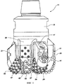
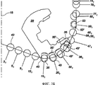
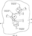
на фиг.1 представлено гибридное долото в соответствии с настоящим изобретением;figure 1 presents a hybrid bit in accordance with the present invention;
на фиг.2 представлен вид спереди или в плане варианта осуществления гибридного долота, показанного на фиг.1;figure 2 presents a front view or in plan of a variant of implementation of the hybrid bit shown in figure 1;
на фиг.2А представлен вид основного резца и дублирующего резца гибридного долота;on figa presents a view of the main cutter and the backup cutter of the hybrid bit;
на фиг.2Б представлен вид основного резца и дублирующего резца гибридного долота;on figb presents a view of the main cutter and the backup cutter of the hybrid bit;
на фиг.2В представлен вид дублирующего резца на лопасти гибридного долота;on figv presents a view of the backup cutter on the blades of the hybrid bit;
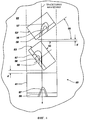
на фиг.2Г представлен вид, иллюстрирующий боковой передний наклон дублирующего резца на лопасти гибридного долота;2G is a view illustrating a lateral front tilt of a duplicate cutter on a hybrid bit blade;
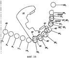
на фиг.3 представлена схема расположения резцов гибридного долота в соответствии с настоящим изобретением;figure 3 presents the layout of the cutters of the hybrid bit in accordance with the present invention;
на фиг.3А-3В представлены схемы расположения резцов на лопасти и шарошке гибридного долота;on figa-3B presents the location of the incisors on the blades and cone of the hybrid bit;
на фиг.4А-4Ж представлены виды сверху комплектов, расположенных по линии резцов гибридного долота.on figa-4G presents top views of sets located along the line of the cutters of the hybrid bit.
Осуществление изобретенияThe implementation of the invention
На фиг.1 и 2 представлен вариант осуществления гибридного долота 11 для бурения подземных пород, в соответствии с настоящим изобретением. Гибридное долото 11 включает корпус 13 долота, верхняя часть которого имеет резьбу или иным образом приспособлена для присоединения к бурильной колонне. Корпус 13 долота может быть выполнен из стали или твердосплавного матричного материала (например, карбида вольфрама) со стальными вставками. Ось или центральная линия 15 корпуса 13 долота в большинстве случаев совпадает с осью вращения бурового долота 11. В гибридном долоте 11, показанном на фиг.1 и 2, может использоваться конфигурация с "ведущей шарошкой", когда шарошка идет впереди фиксированной режущей лопасти, конфигурация с "ведущей лопастью", когда фиксированная режущая лопасть идет впереди шарошки на гибридном долоте, или конфигурация с "противолежащими резцами", когда шарошка расположена напротив фиксированной режущей лопасти. В гибридных долотах всех этих типов, включающих описанные здесь фиксированные режущие лопасти и шарошки, гибридное долото включает дублирующие резцы на фиксированных режущих лопастях, имеющие большой боковой передний угол.1 and 2 show an embodiment of a
На фиг.1 от корпуса 13 долота вдоль оси вниз отходят три лапы 17, 19 (не показаны) 21 долота. С каждой лапой долота связан компенсатор смазки для выравнивания колебаний давления в смазке, подаваемой для смазки подшипника в лапе долота. Между лапами 17, 19, 21 долота вниз от корпуса 13 долота вдоль оси отходят три фиксированных режущих лопасти 23, 25, 27.In Fig. 1, three
На каждой лапе 17, 19, 21 долота установлены вращающиеся шарошки 29, 31, 33 (обычно на подшипниках скольжения, но могут быть использованы подшипники качения и другие подшипники). На каждой шарошке 29, 31, 33 имеется несколько режущих элементов 35, 37, 39 шарошки, расположенных на ней в основном рядами по окружности. В представленном варианте осуществления режущие элементы 35, 37, 39 шарошек представляют собой вставки из карбида вольфрама, установленные на тугой посадке в отверстия или гнезда, сформированные в каждой шарошке 29, 31, 33. В альтернативном варианте режущие элементы 35, 37, 39 шарошек могут быть сформированы совместно с шарошкой и подвергнуты поверхностному упрочнению, как в шарошках со стальными или фрезерованными зубьями. Для режущих элементов 35, 37, 39 шарошек также могут быть использованы иные материалы, помимо карбида вольфрама, например поликристаллический алмаз или другие сверхтвердые или суперабразивные материалы.Rotating
Несколько режущих элементов 41, 43, 45 фиксированных лопастей расположены в ряд на ведущей кромке каждой фиксированной режущей лопасти 23, 25, 27, соответственно. Каждый режущий элемент 41, 43, 45 фиксированной лопасти представляет собой круглый диск из поликристаллического алмаза, установленный на штифте из карбида вольфрама или другого твердого металла, который в свою очередь прикреплен пайкой, пайкой тугоплавким припоем или иным способом к ведущей кромке каждой фиксированной режущей лопасти. Также может быть использован термостабильный поликристаллический алмаз или иной обычный материал для режущих элементов фиксированной лопасти. Каждый ряд основных фиксированных режущих элементов 41, 43, 45 на каждой из фиксированных режущих лопастей 23, 25, 27 расходится от центральной части корпуса 13 долота к радиально наиболее удаленной или калибрующей части на поверхности корпуса 13 долота. В по меньшей мере одном из рядов на одной из фиксированных режущих лопастях 23, 25, 27 режущий элемент фиксированной лопасти расположен на центральной линии 15 корпуса 13 долота или вблизи нее ("на или вблизи" означает, что какая-то часть режущего элемента фиксированной лопасти находится на центральной линии 15 или в пределах интервала 0,040 дюйма от нее). В представленном варианте осуществления окружность ближайшего к центру режущего элемента 41 фиксированной лопасти в ряду на фиксированной режущей лопасти 23 является касательной к оси или центральной линии 15 корпуса 13 долота и долота 11.Several cutting
На радиально наиболее удаленной или калибрующей поверхности или калибрующей накладке каждой фиксированной режущей лопасти 23, 25, 27 сформировано несколько износостойких вставок с плоским верхом из карбида вольфрама или аналогичного твердого металла. Эти вставки предназначены для защиты этой части долота от абразивного износа в результате контакта с боковой стенкой буровой скважины. Кроме того, на каждом фиксированной режущей лопасти 23, 25, 27 между его ведущей и задней кромками имеется ряд каждых из дублирующих резцов 53, 53'. Дублирующие резцы 53, 53' могут быть расположены по линии с основными режущими элементами 41, 43, 45 фиксированных лопастей на соответствующих фиксированных режущих лопастях 23, 25, 27 так, что они прорезают ту же полосу, или канавку, или желобок, что и основные режущие элементы фиксированной лопасти. В альтернативном варианте они могут быть радиально разнесены с основными режущими элементами фиксированной лопасти так, что будут прорезать между канавками или желобками, создаваемыми основными режущими элементами, расположенными на соответствующих фиксированных режущих лопастях. Кроме того, дублирующие резцы 53, 53' создают дополнительные точки контакта или захвата между гибридным долотом 11 и пробуриваемой породой, повышая тем самым стабильность работы гибридного долота 11.On the radially outermost or gage surface or gage pad of each
Фиг.2 иллюстрирует вариант осуществления гибридного долота 11 для бурения подземных пород, имеющего конфигурацию с "противолежащими резцами", когда шарошка расположена напротив фиксированной режущей лопасти гибридного долота 11 с фиксированными режущими лопастями 23, 25, 27 и шарошками 29, 31, 33, в соответствии с настоящим изобретением. Режущие элементы 35, 37, 39 на каждой из шарошек 29, 31, 33, соответственно, расположены так, чтобы прорезать ту же полосу, или канавку, или желобок, что и основные режущие элементы 43, 45, 41 на противолежащих или противоположных фиксированных режущих лопастях 25, 27, 23, соответственно, гибридного долота 11. Таким образом, режущие элементы 35 на шарошке 29 попадают на ту же полосу или канавку или желоб или траекторию вращения, что и режущие элементы 43 на противоположной фиксированной режущей лопасти 25. То же справедливо и для режущих элементов 37 на шарошке 31 и режущих элементов 45 на противоположной фиксированной режущей лопасти 27; и для режущих элементов 39 на шарошке 33 и режущих элементов 41 на противоположной фиксированной режущей лопасти 23. Такая конфигурация режущих элементов гибридного долота 11 обычно называется конфигурацией с "противолежащими резцами". При таком расположении скорее режущие элементы на фиксированной режущей лопасти или шарошке лежат напротив режущих элементов на противоположной или противолежащей шарошке или фиксированной режущей лопасти, нежели режущие элементы на фиксированной режущей лопасти или шарошке "идут впереди" режущих элементов на идущей сзади шарошке или фиксированной режущей лопасти.Figure 2 illustrates an embodiment of a
В варианте осуществления, представленном на фиг.2, шарошки 29, 31, 33 расположены под углом примерно 120 градусов друг к другу (измеряется между их осями вращения). Ось вращения каждой шарошки 29, 31, 33 пересекает ось 15 корпуса 13 долота или гибридного долота 11, хотя каждая из шарошек 29, 31, 33, или все они, могут быть отклонены на любой требуемый угол и (или) иметь поперечное смещение так, чтобы их собственные оси не пересекали оси корпуса 13 долота или гибридного долота 11.In the embodiment of FIG. 2,
Проходы 20 для бурового раствора лежат между лопастями 29, 31, 33, и буровой раствор в них попадает из отверстий 120, которыми кончаются каналы, ведущие от напорной камеры, проходящей в корпусе долота от трубчатого хвостовика (см фиг.1) в верхней части гибридного долота 11. В отверстиях 120 могут быть закреплены любые необходимые промывочные насадки для улучшения параметров потока промывочного раствора и управления им. Проходы 120 для бурового раствора проходят к канавкам для выноса бурового шлама, проходящим вверх вдоль боковой поверхности гибридного долота 11 между фиксированными режущими лопастями 23, 25, 27. Калибрующие накладки (см. фиг.1) образуют проходящие продольно вверх продолжения фиксированных режущих лопастей 23, 25, 27 и могут включать износостойкие вставки или покрытия на своих радиально наружных поверхностях, как это известно в уровне техники. Обломки породы уносятся от резцов 41, 43, 45 буровым раствором (не показаны), выходящим из отверстий 120 и проходящим в целом по радиусу наружу по проходам 20 для бурового раствора и далее вверх по канавкам для выноса бурового шлама в кольцевое пространство между бурильной колонной и стенкой буровой скважины. Буровой раствор обеспечивает охлаждение основным резцам 41, 43, 45 на фиксированных режущих лопастях 23, 25, 27 в процессе бурения и смывает обломки породы с торцевой поверхности гибридного долота 11.Drilling
Каждый из резцов 41, 43, 45 в этом варианте осуществления является ПКА (поликристаллический алмаз) резцом. Однако считается, что любой другой режущий элемент подходящего типа может быть использован в представленных вариантах осуществления изобретения. Для ясности и простоты описания и представления изобретения резцы показаны как единые конструкции, однако понятно, что резцы 41, 43, 45 могут включать слои материалов. Например, ПКА резцы 41, 43, 45 в настоящем варианте изобретения каждый могут включать алмазную пластинку, прикрепленную к несущей подложке, как было упомянуто ранее. При вращении гибридного бурового долота 11, ПКА резцы 41, 43, 45 удаляют материал подстилающих подземных пород срезающим действием при соприкосновении с породой режущих кромок резцов 41, 43, 45. Выбуренная порода распределяется в потоке бурового раствора с образованием взвеси, и смесь с частицами уносится через канавки для выноса бурового шлама.Each of the
Каждая из фиксированных режущих лопастей 23, 25, 27 рассматривается как основная лопасть. Фиксированная режущая лопасть 23, так же, как и фиксированные режущие лопасти 25, 27, в качестве основной лопасти включает коническую часть, и носовую часть и часть перегиба, которая проходит (выступает радиально и продольно) от торцевой поверхности к калибрующей поверхности гибридного долота 11. Как показано, некоторые из дублирующих резцов 53, 53', более конкретно дублирующие резцы 53', гибридного долота 11 установлены под большим боковым передним углом, составляющим примерно от 10° до 60° или, в альтернативном варианте, примерно от 5° до 75°, как показано в настоящем описании и изображено на фиг.2А-2Г и фиг.4-4Е для того, чтобы предотвратить накапливание обломков и осколков перед режущими элементами 53, 53', в результате чего снижается их эффективность. Боковой передний угол дублирующих резцов 53, 53' зависит от необходимой степени отклонения обломков и от желательного пути их движения к открытым пространствам между задней частью фиксированной лопасти и фронтальной частью шарошек, размера гибридного бурового долота 11, конструкции гидравлической системы гибридного долота, числа режущих элементов, например, 41, 53, 53' на фиксированной режущей лопасти 23 гибридного долота 11, и общего числа фиксированных лопастей и шарошек.Each of the fixed
На фиксированной режущей лопасти 23, 25, 27 гибридного долота 11 могут быть расположены один или более дополнительных рядов дублирующих резцов 53, 53', идущих сзади по направлению вращения и дополняющих основные резцы 41, 43, 45 каждой фиксированной режущей лопасти 23, 25, 27, и дублирующие резцы 53, 53'. Каждый из одного или более дополнительных рядов дублирующих резцов, ряда дублирующих резцов и ряда основных резцов включают один или более режущих элементов на одной и той же лопасти. Каждый из режущих элементов одного или более дополнительных рядов дублирующих резцов могут располагаться на одной или по существу на одной линии на концентрической полосе или канавке на траектории вращения с режущими элементами ряда, предшествующими ему на траектории вращения. В варианте осуществления каждый режущий элемент может следовать на круговой траектории с некоторым смещением от центра описываемой при вращении полосы, или канавки, или вращательной траектории режущих элементов, расположенных в ряду дублирующих резцов и основных режущих элементов 41, 43, 45 каждой фиксированной режущей лопасти 23, 25, 27.On the fixed
Каждый дополнительный дублирующий резец может иметь индивидуальную величину выступа относительно предшествующего дублирующего резца на предшествующей режущей лопасти 23, 25, 27 гибридного долота 11. Например, каждый дублирующий резец может обладать одинаковым выступом, либо может иметь ступенчато уменьшающуюся величину выступа по сравнению с предыдущим дублирующим резцом, то есть каждый дублирующий резец имеет все меньшую величину выступа по отношению к предыдущему дублирующему резцу. В варианте осуществления каждый следующий дублирующий резец может иметь уменьшенную в большей или меньшей степени величину выступа относительно предшествующего ему дублирующего резца. Подбирая величину снижения величины выступа для дублирующих резцов, дублирующие резцы можно сделать такими, чтобы они вступали в соприкосновение с материалом породы по мере прогрессивного увеличения площади кромки износа, начиная с основных резцов, и далее у следующих за ними дублирующих резцов. Таким путем можно сделать так, чтобы дублирующие резцы продлевали срок службы гибридного долота 11. Как правило, основной режущий элемент, например 41, 43, 45, располагается обычно в передней части фиксированной режущей лопасти 23, 27, 25, принимая на себя большую часть нагрузки по срезанию породы, особенно при небольшом износе резцов. По мере того как основные режущие элементы 41, 43, 45 подвергаются вредным динамическим воздействиям или по мере износа режущих элементов, дублирующие резцы начинают захватывать породу и начинают принимать на себя нагрузку от основных резцов для улучшения удаления материала породы.Each additional duplicating cutter may have an individual protrusion value relative to the previous duplicating cutter on the
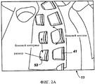
На фиг.2А представлен вид фрагмента роторного лопастного долота 11, иллюстрирующий понятия бокового переднего наклона резца (боковой передний наклон) в отношении резцов 41, размещения резцов (боковой интервал) в отношении дублирующих резцов 53 и размера резца (размер). "Боковой передний наклон" описан выше. "Боковой интервал" представляет собой величину расстояния между резцами в соседних рядах резцов. "Размер" представляет размер резца, на который обычно указывает диаметр резцов.FIG. 2A is a fragmentary view of a
На фиг.2Б представлен вид сбоку фрагмента роторного лопастного долота, показанного на фиг.2, иллюстрирующий понятия продольного переднего наклона в отношении дублирующих резцов 53, выступа и фаски в отношении резцов 41 и интервала в отношении резцов 41 и дублирующих резцов 53.On figb presents a side view of a fragment of the rotary blade of the bit shown in figure 2, illustrating the concepts of longitudinal front inclination in relation to the
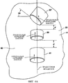
На фиг.2В представлен вид сечения через середину дублирующего резца 53, 53', расположенного на лопасти 23, 25, 27 гибридного долота 11 (фиг.1). Направление резания представлено стрелкой 72. Резцы 53, 53' могут быть установлены на фиксированных режущих лопастях 23, 25, 27 с такой ориентацией, что режущая кромка резца 53, 53' расположена под продольным передним углом 74 по отношению к линии 80. Линия 80 может быть определена как линия, проходящая радиально наружу от торцевой поверхности бурового долота 11 в направлении, в целом перпендикулярном к ней в этом месте. Дополнительно, или в качестве альтернативы, линия 80 может быть определена как линия, проходящая радиально наружу от торцевой поверхности бурового долота 11 в направлении, в целом перпендикулярном к направлению 72 резания. Продольный передний угол 74 может быть измерен относительно линии 80, при этом положительные углы отсчитываются в направлении против часовой стрелки, а отрицательные углы отсчитываются по часовой стрелке.FIG. 2B is a sectional view through the middle of the
Резец 53, 53', показанный на фиг.2В, имеет положительный продольный передний угол, равный примерно 20°, иллюстрирующий "наклон назад". В других вариантах осуществления резец 53, 53' может иметь отрицательный продольный передний угол. В таких конфигурациях можно сказать, что резец 53, 53' имеет "наклон вперед". В качестве частного варианта, не ограничивающего изобретение, каждый резец 53, 53' на торцевой поверхности бурового долота, показанного на фиг.1, может обычно иметь продольный передний угол в интервале примерно от 5° до 30°.The
На фиг.2Г приведено увеличенное изображение фрагмента резца 53, 53', установленного на фиксированной режущей лопасти 23, 25, 27 на торцевой поверхности бурового долота 11, показанного на фиг.1. Направление резания представлено стрелкой 72. Ориентация установки резца 53, 53' на лопасти 23, 25, 27 может быть такой, что режущая кромка резца 53, 53' будет расположена в целом перпендикулярно направлению 72 резания. При таком расположении резец 53, 53' не имеет бокового наклона. Боковой передний угол резца 53, 53' может быть определен как угол между линией 82, направленной в целом перпендикулярно направлению резания, и режущей кромкой резца 53, 53', при этом положительные углы отсчитываются в направлении против часовой стрелки, а отрицательные углы отсчитываются по часовой стрелке. В дополнительных вариантах резец 53, 53' может быть установлен с ориентацией, показанной пунктирной линией 78А. В такой конфигурации резец 53, 53' может иметь отрицательный боковой передний (SR) угол 76А. Кроме того, резец 53, 53' может иметь ориентацию, представленную пунктирной линией 78В. В этой конфигурации резец 53, 53' может иметь положительный боковой передний угол 76В. В качестве частного варианта, не ограничивающего изобретения, каждый резец 53, 53' на торцевой поверхности бурового долота 11, показанного на фиг.1, может иметь боковой передний угол, составляющий в интервале примерно от 10° до 60°, или, в альтернативном случае, примерно от 5° до 75°, хотя при необходимости они могут быть установлены и с отрицательным боковым передним углом, примерно в том же интервале значений или большем.On Fig.2G shows an enlarged image of a fragment of the
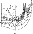
На фиг.3 представлен, в целом, режущий профиль фиксированных режущих элементов 41, 43, 45 на фиксированных режущих лопастях 23, 25, 27, и режущих элементов 35, 37, 39 на шарошках 29, 33, 31. Видно, что самый внутренний режущий элемент 41 на фиксированной режущей лопасти 23 образует касательную к оси 15 корпуса 13 долота гибридного долота 11. Показаны следующий самый внутренний режущий элемент 45 на фиксированной режущей лопасти 27 и также третий самый внутренний режущий элемент 43 на фиксированной режущей лопасти 25. Режущий элемент 39 на шарошке 33 показан с той же глубиной резания или выступом, что и режущий элемент 41 на фиксированной режущей лопасти 23, и каждый из них расположен на одной и той же осевой линии и прорезают одну и ту же полосу, или канавку, или желобок, или траекторию вращения. Видно, что некоторые режущие элементы 41 на фиксированной режущей лопасти 23 расположены в конической части гибридного долота 11, в то время как другие режущие элементы 41 расположены в носовой части, части перегиба и калибрующей части гибридного долота 11. Режущие элементы 39 шарошки 33, прорезают ту же полосу, или канавку, или желобок или траекторию вращения, что и режущие элементы 41 в носовой части или части перегиба гибридного долота 11. Режущие элементы 35, 37, 39 на шарошках 29, 31, 33 не заходят в коническую часть гибридного долота 11, а в целом расположены в носовой части и части перегиба гибридного долота 11, до калибрующей части гибридного долота 11. На фиг.3 также показаны режущие элементы 35, 37 на шарошках 29 и 31, и их соотношение с режущими элементами 43 и 45 на фиксированных режущих лопастях 25, 27, прорезающих при вращении гибридного бурового долота 11 ту же полосу, или канавку, или желобок, или траекторию вращения, либо по центру той же полосы или канавки или желобка или траектории вращения, либо со смещением. Каждый режущий элемент 41, 43, 45 и режущий элемент 35, 37, 39 были показаны имеющими либо одинаковый выступ глубины резания, либо различный выступ глубины резания так, что каждый режущий элемент вырезает либо то же самое количество породы, либо различное количество породы в различных областях установки режущих элементов на гибридном долоте 11. Глубина резания для каждого режущего элемента может быть, при необходимости, различной в одной и той же полосе или канавке или желобке или траектории вращения.Figure 3 shows, in General, the cutting profile of the fixed
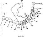
На фиг.3А показано соотношение режущих профилей фиксированных режущих элементов 41 на фиксированной режущей лопасти 23 и режущих элементов 39 на шарошке 33. Фиксированная режущая лопасть 23 и шарошка 33 представляют собой пару резцов на гибридном долоте 11 в виде пары противолежащего резца и шарошки. Видно, что некоторые из режущих элементов 41 на фиксированной режущей лопасти 23 и режущих элементов 39 на шарошке 33 имеют общий центр и прорезают ту же полосу, или канавку, или желобок, в то время как другие режущие элементы 41' на фиксированной режущей лопасти 23 и режущие элементы 39' на шарошке 33 не имеют общего центра, но все равно прорезают одну и ту же полосу, или канавку, или желобок, или траекторию вращения. Показано, что все режущие элементы 41 и 41' на фиксированной режущей лопасти 23, и режущие элементы 39 и 39' на шарошке 33 имеют одинаковый выступ или различный выступ, прорезая породу при вращении гибридного бурового долота 11 либо на одинаковую глубину, либо на разную глубину, хотя эта глубина может быть изменена при необходимости. На фиг.3А также показаны дублирующие режущие элементы 53, 53' на фиксированной лопасти 23, расположенные за режущими элементами 41. Дублирующие режущие элементы 53, 53' могут иметь такой же выступ, либо меньший выступ, либо, при необходимости, больший выступ, чем основные режущие элементы 41, и могут иметь такой же диаметр или меньший диаметр, чем режущий элемент 41. Кроме того, дублирующие режущие элементы 53, 53', прорезая ту же ту же полосу, или канавку, или желобок, или траекторию вращения, что и режущий элемент 41, могут быть расположены со смещением от центра режущего элемента 41, находящегося впереди ассоциированного с ним дублирующего режущего элемента 53, 53'. Таким путем режущие элементы 41 и дублирующие режущие элементы 53, 53' на фиксированной лопасти 23, и режущие элементы 39 на шарошке 33, все будут прорезать одну и ту же полосу, или канавку, или желобок, или траекторию вращения, имея общий центр или имея слегка разнесенные центры, имея одинаковый выступ резания или, напротив, меньший выступ резания.3A shows the ratio of the cutting profiles of the fixed
На фиг.3Б представлено соотношение режущих профилей фиксированных режущих элементов 43 на фиксированной режущей лопасти 25 и режущих элементов 35 на шарошке 29. Фиксированная режущая лопасть 25 и шарошка 29 образуют пару резцов на гибридном долоте 11 в виде пары противолежащего резца и шарошки. Видно, что некоторые из режущих элементов 43 на фиксированной режущей лопасти 25 и режущих элементов 35 на шарошке 29 имеют общий центр и прорезают ту же полосу, или канавку, или желобок, или траекторию вращения, в то время как другие режущие элементы 43' на фиксированной режущей лопасти 25 и режущие элементы 35' на шарошке 29 не имеют общего центра, но все равно прорезают одну и ту же полосу, или канавку, или желобок или траекторию вращения. Показано, что все режущие элементы 43 и 43' на фиксированной режущей лопасти 25, и режущие элементы 35 и 35' на шарошке 29 имеют одинаковый выступ, или меньший выступ, или различный выступ, прорезая породу при вращении гибридного бурового долота 11 либо на одинаковую глубину, либо на разную глубину, хотя эта глубина может быть изменена при необходимости. На фиг.3Б также показаны дублирующие режущие элементы 53, 53' на фиксированной лопасти 25, расположенные за режущими элементами 43. Дублирующие режущие элементы 53, 53' могут иметь такой же выступ, либо меньший выступ, либо, при необходимости, больший выступ резания, чем режущие элементы 43, и могут иметь такой же диаметр или меньший диаметр, чем режущий элемент 43. Кроме того, дублирующие режущие элементы 53, 53', прорезая ту же ту же полосу, или канавку, или желобок, или траекторию вращения, что и режущий элемент 43', могут быть расположены со смещением от центра режущего элемента 43, находящегося впереди ассоциированного с ним дублирующего режущего элемента 53, 53'. Таким путем, режущие элементы 43 и дублирующие режущие элементы 53, 53' на фиксированной лопасти 25, и режущие элементы 35 на шарошке 29, все будут прорезать одну и ту же полосу, или канавку, или желобок или траекторию вращения, имея общий центр или имея слегка разнесенные центры, имея одинаковый выступ резания или, напротив, меньший выступ резания.On figb presents the ratio of the cutting profiles of the fixed
На фиг.3В представлено соотношение режущих профилей фиксированных режущих элементов 45 на фиксированной режущей лопасти 27 и режущих элементов 37 на шарошке 31, при этом фиксированная режущая лопасть 27 и шарошка 31 образуют пару резцов на гибридном долоте 11 в виде пары противолежащего резца и шарошки. Видно, что некоторые из режущих элементов 45 на фиксированной режущей лопасти 27 и режущих элементов 37 на шарошке 31 имеют общий центр и прорезают ту же полосу, или канавку, или желобок, или траекторию вращения, в то время как другие режущие элементы 45' на фиксированной режущей лопасти 27 и режущие элементы 37' на шарошке 31 не имеют общего центра, но все равно прорезают одну и ту же полосу, или канавку, или желобок. Показано, что все режущие элементы 45 и 45' на фиксированной режущей лопасти 27, и режущие элементы 37 и 37' на шарошке 31 имеют одинаковый выступ или различный выступ, прорезая породу при вращении гибридного бурового долота 11 либо на одинаковую глубину, либо на разную глубину, хотя эта глубина может быть изменена при необходимости. На фиг.3В также показаны дублирующие режущие элементы 53, 53' на фиксированной лопасти 27, расположенные за режущими элементами 45. Дублирующие режущие элементы 53, 53' могут иметь такой же выступ, либо меньший выступ, либо, при необходимости, больший выступ резания, чем режущие элементы 45, и могут иметь такой же диаметр или меньший диаметр, чем режущий элемент 45. Кроме того, дублирующие режущие элементы 53, 53', прорезая ту же ту же полосу, или канавку, или желобок, или траекторию вращения, что и режущий элемент 45, могут быть расположены со смещением от центра режущего элемента 45, находящегося впереди ассоциированного с ним дублирующего режущего элемента 53, 53'. Таким путем, режущие элементы 45 и дублирующие режущие элементы 53, 53' на фиксированной лопасти 27, и режущие элементы 37 на шарошке 31, все будут прорезать одну и ту же полосу, или канавку, или желобок, или траекторию вращения, имея общий центр или имея слегка разнесенные центры, имея одинаковый выступ резания или, напротив, меньший выступ резания.FIG. 3B shows the ratio of the cutting profiles of the fixed
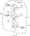
В первом примере резцов 41, 53, 53' гибридного долота 11, на фиг.4 представлен вид сверху комплекта 60 расположенных по линии резцов, включающего два резца 53, 53' с боковым наклоном. Основной резец 41 и дублирующие резцы 53, 53' разнесены друг от друга на требуемое расстояние d. На фиг.4 показано линейное представление вращательной или спиральной полосы, или канавки, или траектории вращения, по которой может быть ориентирован комплект 60 расположенных по линии резцов на роторном лопастном долоте. Комплект 60 расположенных по линии резцов включает основной резец 41 и два резца 53, 53' с боковым наклоном. Резец 53 с боковым наклоном следует по траектории вращения за основным резцом 41 и имеет боковой передний угол 55, который может быть любым боковым передним углом отклонения влево от траектории вращения, например, примерно от 5° до 75°. Резец 53' с боковым наклоном также имеет боковой передний угол отклонения вправо от траектории вращения, или в противоположном направлении от отклонения резца 53 с боковым наклоном, как это показано на чертеже. Хотя в комплекте 60 расположенных по линии резцов имеется два резца 53, 53' с боковым наклоном, могут быть использованы и дополнительные резцы с боковым наклоном. В то время как на основном резце 41 по мере его износа могут образоваться кромки износа 56, 57, при введении бокового переднего угла 55 резцы 53, 53' с боковым наклоном своими верхними кромками 58, 59, соответственно, прорезают параллельные полосы, или желобки, или траектории вращения, увеличивая скорость проходки долота и также направляя движение создаваемых долотом обломков. Кроме того, по мере роста кромок износа 56, 57 на основном резце 41, верхние кромки 58, 59 резцов 53, 53' могут более эффективно дробить и удалять материал породы с каждой стороны основного резца 41. В то время как комплект 60 резцов показан с нулевым передним углом наклона основного резца 41 и резцов 53, 53' с боковым наклоном, резцы 41, 53, 53' могут иметь любой необходимый передний угол. В то время как резец 53, 53' с боковым наклоном включен в комплект 60 расположенных по линии резцов, резец 53, 53' с боковым наклоном может быть использован в любом комплекте дублирующих резцов, комплекте нескольких дублирующих резцов, ряду резцов, ряду нескольких дублирующих резцов, ряду резцов, разнесенных в разные стороны, и комплекте резцов, разнесенных в разные стороны, любым необходимым образом. Траектория вращения на фиг.4 является линейным представлением траектории вращения или полосы или канавки или спиральной траектории, по которой может быть ориентирован комплект 60 расположенных по линии резцов на гибридном долоте 11.In the first example of the
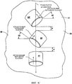
На фиг.4А представлен на виде сверху комплект 60 расположенных по линии резцов, включающий основной резец 41, дублирующий резец 53 и дублирующий резец 53', которые имеют общую ось на гибридном долоте 11, показанную как траекторию вращения для комплекта 60 резцов, при этом основной резец 41 также имеет любой необходимый продольный передний угол, диаметр дублирующего резца 53 меньше диаметра основного резца 41 и его продольный передний угол имеет любое требуемое значение, а дублирующий резец 53' имеет диаметр, равный диаметру основного резца 41, имеет любой требуемый продольный передний угол и любой требуемый боковой передний угол 55 отклонения влево от направления траектории вращения, например, примерно от 10° до 60°, либо в альтернативном варианте, примерно от 5° до 75°, по отношению к траектории вращения комплекта 60 резцов. Основной резец 41 и дублирующие резцы 53, 53' разнесены друг от друга на лопасти 23 на расстояние d, располагаясь на одной траектории вращения. Траектория вращения на фиг.4А является линейным представлением траектории вращения или полосы или канавки или спиральной траектории, по которой может быть ориентирован комплект 60 расположенных по линии резцов на роторном лопастном долоте 11.FIG. 4A is a plan view of a
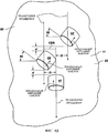
На фиг.4Б представлен на виде сверху комплект 60 расположенных по линии резцов для гибридного долота 11, включающий основной резец 41, и два дублирующих резца 53, 53' с продольным передним наклоном и с боковым передним наклоном, имеющие все одинаковый диаметр, любые необходимые продольные передние углы и любые необходимые боковые передние углы наклона. Основной резец 41 и дублирующие резцы 53, 53' разнесены на лопасти 23 на любое требуемое расстояние d. Дублирующие резцы 53, 53' имеют любой необходимый боковой передний угол 55. Основной резец 41 и резцы 53, 53' с боковым передним наклоном также имеют любой необходимый продольный передний наклон. На фиг.4Б приведено линейное представление вращательной или спиральной траектории, по которой может быть ориентирован комплект 60 расположенных по линии резцов на гибридном долоте 11. Дублирующий резец 53 с продольным передним наклоном и боковым передним наклоном идет вслед по направлению вращения за основным резцом 41 с продольным передним наклоном, в то время как дублирующий резец 53' с продольным передним наклоном и боковым передним наклоном идет вслед за дублирующим резцом 53. Резец 53 с продольным передним наклоном и боковым передним наклоном имеет угол 55 бокового переднего наклона, составляющий примерно от 10° до 60° или, в альтернативном варианте, примерно от 5° до 75°, влево от полосы, или канавки, или траектории вращения. Хотя в комплекте 60 расположенных по линии резцов имеются два дублирующих резца 53, 53' с продольным передним наклоном и боковым передним наклоном, могут быть использованы и дополнительные дублирующие резцы с продольным передним и боковым передним наклоном.Fig. 4B is a plan view showing a
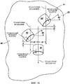
На фиг.4В представлен на виде сверху комплект 60 расположенных по линии резцов для гибридного долота 11, включающий основной резец 41 и два дублирующих резца 53, 53' с продольным передним наклоном и боковым передним наклоном, которые имеют одинаковый диаметр, и необходимый продольный передний угол, и любой необходимый боковой передний угол. Основной резец 41 и резцы 53, 53' с передним боковым наклоном разнесены на лопасти 23 на любое требуемое расстояние d. Дублирующие резцы 53, 53' имеют поэтому любой необходимый боковой передний угол 55. Основной резец 41 и резцы 53, 53' с боковым передним наклоном также имеют любой необходимый продольный передний наклон. На фиг.4Б приведено линейное представление вращательной или спиральной траектории, по которой может быть ориентирован комплект 60 расположенных по линии резцов на лопасти гибридного долота 11. Дублирующий резец 53 с продольным передним наклоном и боковым передним наклоном идет вслед по направлению вращения за основным резцом 41 с продольным передним наклоном, в то время как дублирующий резец 53' с продольным передним наклоном и боковым передним наклоном идет вслед за дублирующим резцом 53. Резец 53 с продольным передним наклоном и боковым передним наклоном имеет угол 55 бокового переднего наклона, составляющий, например, примерно от 10° до 60° или, в альтернативном варианте, примерно от 5° до 75°, вправо от полосы или канавки или траектории вращения. Хотя в комплекте 60 расположенных по линии резцов имеются два дублирующих резца 53, 53' с продольным передним наклоном и боковым передним наклоном, могут быть использованы и дополнительные дублирующие резцы с продольным передним и боковым передним наклоном.FIG. 4B is a plan view of a
На фиг.4Г представлен на виде сверху комплект 60 расположенных по линии резцов для гибридного долота 11, включающий основной резец 41 с продольным передним наклоном и два дублирующих резца 53, 53' с продольным передним наклоном и боковым передним наклоном, которые имеют одинаковый диаметр, любой необходимый продольный передний угол и любой необходимый боковой передний угол. Основной резец 41 и резцы 53, 53' с передним боковым наклоном разнесены на лопасти 23 на любое требуемое расстояние d. На фиг.4Г приведено линейное представление вращательной или спиральной траектории, по которой может быть ориентирован комплект 60 расположенных по линии резцов на лопасти 23 гибридного долота 11. Дублирующий резец 53 с продольным передним наклоном и боковым передним наклоном идет вслед по направлению вращения за основным резцом 41 с продольным передним наклоном, в то время как дублирующий резец 53' с продольным передним наклоном и боковым передним наклоном идет вслед за дублирующим резцом 53. Резцы 53, 53' с продольным передним наклоном и боковым передним наклоном имеют угол 55 бокового переднего наклона, составляющий, например, примерно от 10° до 60° или, в альтернативном варианте, примерно от 5° до 75°, влево и вправо относительно полосы, или канавки, или траектории вращения. Хотя в комплекте 60 расположенных по линии резцов имеются два дублирующих резца 53, 53' с продольным передним наклоном и боковым передним наклоном, могут быть использованы и дополнительные дублирующие резцы с продольным передним и боковым передним наклоном.FIG. 4G shows a plan view of a
На фиг.4Д представлен на виде сверху комплект 60 расположенных по линии резцов для гибридного долота 11, включающий основной резец 41 с продольным передним наклоном и два дублирующих резца 53, 53' с продольным передним наклоном и боковым передним наклоном, где резцы 53, 53' с боковым передним наклоном имеют угол бокового переднего наклона одного направления, влево от траектории вращения основного резца 41, и смещены на расстояние D, каждый вблизи полосы, или канавки, или траектории вращения влево и вправо от траектории вращения основного резца 41, соответственно, при этом следуя в целом по полосе, или канавке, или траектории вращения основного резца 41. Величина расстояния D, на которое дублирующие резцы 53, 53' смещены от траектории вращения основного резца 41, будет определять, является или нет дублирующий резец 53, 53' резцом ведущей лопасти или резцом следующей сзади лопасти относительно соответствующих режущих элементов шарошки, которая может быть ведущей шарошкой или шарошкой, следующей сзади, на гибридном долоте 11. Основной резец 41 и дублирующие резцы 53, 53' также расположены с интервалом d на лопасти 23. Основной резец 41 и дублирующие резцы 53, 53' имеют любой необходимый продольный передний угол, в то время как дублирующие резцы 53, 53' дополнительно имеют любой необходимый боковой передний угол, составляющий примерно от 10° до 60° или, в альтернативном варианте, примерно от 5° до 75°, на лопасти 23 гибридного долота 11. Комплект 60 расположенных по линии резцов включает основной резец 41 с продольным передним наклоном, и дублирующие резцы 53, 53' с продольным передним наклоном и боковым передним наклоном. Дублирующие резцы 53, 53' с продольным передним наклоном и боковым передним наклоном имеют любые необходимые углы 55 бокового переднего наклона, например, примерно от 10° до 60° или, в альтернативном варианте, примерно от 5° до 75°, одинакового направления отклонения - влево.Fig. 4D is a plan view of a
На фиг.4Е представлен на виде сверху комплект 60 расположенных по линии резцов для гибридного долота 11, включающий основной резец 41 с продольным передним наклоном и два дублирующих резца 53, 53' с продольным передним наклоном и боковым передним наклоном, где резцы 53, 53' с боковым передним наклоном имеют угол бокового переднего наклона одного направления, вправо от траектории вращения основного резца 41, и смещены на расстояние D, каждый вблизи полосы или канавки или траектории вращения влево и вправо от траектории вращения основного резца 41, соответственно, при этом следуя в целом по полосе, или канавке, или траектории вращения основного резца 41. Величина расстояния D, на которое дублирующие резцы 53, 53' смещены от траектории вращения основного резца 41, будет определять, является или нет дублирующий резец 53, 53' резцом ведущей лопасти или резцом следующей сзади лопасти относительно соответствующих режущих элементов шарошки, которая может быть ведущей шарошкой или шарошкой, следующей сзади, на гибридном долоте 11. Основной резец 41 и дублирующие резцы 53, 53' также расположены с интервалом d на лопасти 23. Основной резец 41 и дублирующие резцы 53, 53' имеют любой необходимый продольный передний угол, в то время как дублирующие резцы 53, 53' дополнительно имеют любой необходимый боковой передний угол, составляющий примерно от 10° до 60° или, в альтернативном варианте, примерно от 5° до 75°, на лопасти 23 гибридного долота 11. Комплект 60 расположенных по линии резцов включает основной резец 41 с продольным передним наклоном, и дублирующие резцы 53, 53' с продольным передним наклоном и боковым передним наклоном. Дублирующие резцы 53, 53' с продольным передним наклоном и боковым передним наклоном имеют любые необходимые углы 55 бокового переднего наклона, например, примерно от 10° до 60° или, в альтернативном варианте, примерно от 5° до 75°, одинакового направления отклонения - вправо от траектории вращения.FIG. 4E is a plan view of a
На фиг.4Ж представлен на виде сверху комплект 60 расположенных по линии резцов для гибридного долота 11, включающий основной резец 41 с продольным передним наклоном и два дублирующих резца 53, 53' с продольным передним наклоном и боковым передним наклоном, причем резцы 53, 53' с боковым передним наклоном имеют углы бокового переднего наклона противоположных направлений, влево (53) и вправо (53') от траектории вращения основного резца 41, и смещены на расстояние D, каждый вблизи полосы, или канавки, или траектории вращения влево и вправо от траектории вращения основного резца 41, соответственно, при этом следуя в целом по полосе или канавке или траектории вращения основного резца 41. Величина расстояния D, на которое дублирующие резцы 53 и 53' смещены от траектории вращения основного резца 41, будет определять, является или нет дублирующий резец 53, 53' резцом ведущей лопасти или резцом следующей сзади лопасти относительно режущего элемента соответствующей шарошки, которая может быть ведущей шарошкой или шарошкой, следующей сзади, на гибридном долоте 11. Основной резец 41 и дублирующие резцы 53, 53' также расположены с интервалом d на лопасти 23. Основной резец 41 и дублирующие резцы 53, 53' имеют любой необходимый продольный передний угол, в то время как дублирующие резцы 53, 53' дополнительно имеют любой необходимый боковой передний угол, составляющий примерно от 10° до 60° или, в альтернативном варианте, примерно от 5° до 75°, на лопасти 23 гибридного долота 11. Комплект 60 расположенных по линии резцов включает основной резец 41 с продольным передним наклоном, и дублирующие резцы 53, 53' с продольным передним наклоном и боковым передним наклоном. Дублирующие резцы 53, 53' с продольным передним наклоном и боковым передним наклоном имеют любые необходимые углы 55 бокового переднего наклона, например, примерно от 10° до 60° или, в альтернативном варианте, примерно от 5° до 75°, правого и левого направления.FIG. 4G shows a plan view of a set of 60 cutters arranged along the line for the
Хотя конфигурации основного резца 41 и дублирующих резцов 53, 53' описаны в отношении фиксированной режущей лопасти 23, такая конфигурация может быть использована и на лопастях 25, 27.Although the configurations of the
В то время как принципы настоящего изобретения были описаны здесь применительно к вариантам осуществления гибридных буровых долот, настоящее изобретение может быть использовано в бурильном инструменте других типов, например расширителях ствола скважины, роторных буровых долотах, инструменте для проходки восстающих выработок, лопастных долотах, цилиндрических фрезах, резцах для горнорудной промышленности и других подобных структурах, известных в уровне техники, который может быть сформирован способами, реализующими настоящее изобретение. Более того, в то время как настоящее изобретение было описано здесь в отношении определенных предпочтительных вариантов осуществления, специалистам должно быть понятно, что оно только этими вариантами не ограничивается. Напротив, многие добавления, изъятия и изменения к описанным и проиллюстрированным вариантам осуществления могут быть сделаны без отступления от области притязаний заявляемого здесь изобретения. Кроме того, признаки одного варианта осуществления могут быть скомбинированы с признаками другого варианта осуществления, оставаясь в пределах области изобретения, предлагаемой изобретателями.While the principles of the present invention have been described herein in relation to hybrid drill bit embodiments, the present invention can be used in other types of drilling tools, for example, boreholes, rotary drill bits, uprising tools, blade bits, cylindrical cutters, cutters for the mining industry and other similar structures known in the prior art, which can be formed by methods that implement the present invention decay. Moreover, while the present invention has been described herein in relation to certain preferred embodiments, those skilled in the art will appreciate that it is not limited to these options. On the contrary, many additions, deletions, and changes to the described and illustrated embodiments can be made without departing from the scope of the claims of the invention claimed herein. In addition, features of one embodiment may be combined with features of another embodiment, while remaining within the scope of the invention proposed by the inventors.
Claims (17)
Applications Claiming Priority (3)
| Application Number | Priority Date | Filing Date | Title |
|---|---|---|---|
| US12/340,299 | 2008-12-19 | ||
| US12/340,299 US8047307B2 (en) | 2008-12-19 | 2008-12-19 | Hybrid drill bit with secondary backup cutters positioned with high side rake angles |
| PCT/US2009/068399 WO2010080477A2 (en) | 2008-12-19 | 2009-12-17 | Hybrid drill bit with secondary backup cutters positioned with high side rake angles |
Publications (2)
| Publication Number | Publication Date |
|---|---|
| RU2011129553A RU2011129553A (en) | 2013-01-27 |
| RU2531720C2 true RU2531720C2 (en) | 2014-10-27 |
Family
ID=42264426
Family Applications (1)
| Application Number | Title | Priority Date | Filing Date |
|---|---|---|---|
| RU2011129553/03A RU2531720C2 (en) | 2008-12-19 | 2009-12-17 | Hybrid drilling bit with high side front inclination angle of auxiliary backup cutters |
Country Status (7)
| Country | Link |
|---|---|
| US (1) | US8047307B2 (en) |
| EP (1) | EP2370659B1 (en) |
| BR (1) | BRPI0923075B1 (en) |
| CA (1) | CA2746501C (en) |
| MX (1) | MX2011005858A (en) |
| RU (1) | RU2531720C2 (en) |
| WO (1) | WO2010080477A2 (en) |
Cited By (2)
| Publication number | Priority date | Publication date | Assignee | Title |
|---|---|---|---|---|
| RU190616U1 (en) * | 2019-04-23 | 2019-07-04 | Общество с ограниченной ответственностью Научно-производственное предприятие "БУРИНТЕХ" (ООО НПП "БУРИНТЕХ") | HYBRID DRILLING BIT |
| RU2768877C2 (en) * | 2017-11-07 | 2022-03-25 | ВАРЕЛ ИНТЕРНЭШНЛ ИНД., Эл.Эл.Си | Stabilizing drill bit with fixed cutting structure |
Families Citing this family (28)
| Publication number | Priority date | Publication date | Assignee | Title |
|---|---|---|---|---|
| US9574405B2 (en) | 2005-09-21 | 2017-02-21 | Smith International, Inc. | Hybrid disc bit with optimized PDC cutter placement |
| GB2498134B (en) | 2008-12-11 | 2013-11-13 | Halliburton Energy Serv Inc | Multilevel force balanced downhole drilling tools and methods |
| US8141664B2 (en) * | 2009-03-03 | 2012-03-27 | Baker Hughes Incorporated | Hybrid drill bit with high bearing pin angles |
| US8887839B2 (en) * | 2009-06-25 | 2014-11-18 | Baker Hughes Incorporated | Drill bit for use in drilling subterranean formations |
| US8672060B2 (en) * | 2009-07-31 | 2014-03-18 | Smith International, Inc. | High shear roller cone drill bits |
| WO2011084944A2 (en) * | 2010-01-05 | 2011-07-14 | Smith International, Inc. | High-shear roller cone and pdc hybrid bit |
| CN101892810B (en) * | 2010-07-16 | 2012-07-25 | 西南石油大学 | Combined drill breaking rocks by cutting method |
| US9212523B2 (en) * | 2011-12-01 | 2015-12-15 | Smith International, Inc. | Drill bit having geometrically sharp inserts |
| CN102561953B (en) * | 2012-01-18 | 2014-11-05 | 西南石油大学 | Self-adapting hybrid bit |
| WO2014088946A1 (en) | 2012-12-03 | 2014-06-12 | Ulterra Drilling Technologies, L.P. | Earth boring tool with improved arrangment of cutter side rakes |
| CN103015899B (en) * | 2012-12-19 | 2015-07-29 | 江汉石油钻头股份有限公司 | A kind of Mixed drilling bit strengthening heart portion cutting function |
| CN103899253B (en) * | 2012-12-28 | 2016-02-10 | 中国石油化工股份有限公司 | With the drill bit of flexible wing |
| US20140353046A1 (en) * | 2013-05-28 | 2014-12-04 | Smith International, Inc. | Hybrid bit with roller cones near the bit axis |
| CN105612304B (en) | 2013-09-03 | 2018-05-22 | 哈里伯顿能源服务公司 | Include the drilling tool of multiple-step form cutting depth control |
| WO2015094221A1 (en) | 2013-12-18 | 2015-06-25 | Halliburton Energy Services, Inc. | Cutting structure design with secondary cutter methodology |
| CN105723045B (en) | 2013-12-26 | 2019-10-11 | 哈里伯顿能源服务公司 | Multistage dynamic balance downhole well tool including the cutting element in Trajectory Sets configuration |
| CA2930178C (en) | 2013-12-26 | 2019-04-16 | Halliburton Energy Services, Inc. | Multilevel force balanced downhole drilling tools including cutting elements in a step profile configuration |
| WO2017014730A1 (en) | 2015-07-17 | 2017-01-26 | Halliburton Energy Services, Inc. | Hybrid drill bit with counter-rotation cutters in center |
| US10337272B2 (en) * | 2016-02-16 | 2019-07-02 | Varel International Ind., L.P. | Hybrid roller cone and junk mill bit |
| US10196859B2 (en) | 2016-03-04 | 2019-02-05 | Baker Hughes Incorporated | Drill bits, rotatable cutting structures, cutting structures having adjustable rotational resistance, and related methods |
| CN105756564B (en) * | 2016-05-04 | 2018-05-25 | 沧州格锐特钻头有限公司 | A kind of combined type coring PDC bit efficiently crept into |
| CN108798514B (en) * | 2017-04-27 | 2024-01-05 | 西南石油大学 | Directional drilling diamond drill bit |
| CN107143287A (en) * | 2017-07-14 | 2017-09-08 | 宜昌神达石油机械有限公司 | Yangtze Cambrian system shale gas exploitation combined bitses during one kind is applicable |
| CN107747473B (en) * | 2017-11-16 | 2024-04-16 | 中石化江钻石油机械有限公司 | Insert cone hybrid bit |
| CN107905737B (en) | 2017-12-21 | 2021-07-27 | 中石化江钻石油机械有限公司 | Three-stage cutting insert cone hybrid bit |
| CN110685606B (en) * | 2018-07-05 | 2021-11-26 | 成都海锐能源科技有限公司 | Fixed cutting structure-roller composite drill bit |
| US11480016B2 (en) | 2018-11-12 | 2022-10-25 | Ulterra Drilling Technologies, L.P. | Drill bit |
| CN117514016A (en) * | 2024-01-03 | 2024-02-06 | 西南石油大学 | PDC drill bit with reversely-mounted teeth |
Citations (2)
| Publication number | Priority date | Publication date | Assignee | Title |
|---|---|---|---|---|
| SU592956A1 (en) * | 1976-01-07 | 1978-02-15 | Всесоюзный Ордена Трудового Красного Знамени Научно-Исследовательский Институт Буровой Техники | Drilling drag bit |
| SU1472623A1 (en) * | 1986-10-08 | 1989-04-15 | Институт сверхтвердых материалов АН УССР | Rotary drilling bit |
Family Cites Families (173)
| Publication number | Priority date | Publication date | Assignee | Title |
|---|---|---|---|---|
| US228780A (en) * | 1880-06-15 | Theodoee von ringhabzi | ||
| US930759A (en) * | 1908-11-20 | 1909-08-10 | Howard R Hughes | Drill. |
| US1874066A (en) * | 1930-04-28 | 1932-08-30 | Floyd L Scott | Combination rolling and scraping cutter drill |
| US1932487A (en) * | 1930-07-11 | 1933-10-31 | Hughes Tool Co | Combination scraping and rolling cutter drill |
| US1879127A (en) * | 1930-07-21 | 1932-09-27 | Hughes Tool Co | Combination rolling and scraping cutter bit |
| US2030722A (en) * | 1933-12-01 | 1936-02-11 | Hughes Tool Co | Cutter assembly |
| US2198849A (en) * | 1938-06-09 | 1940-04-30 | Reuben L Waxler | Drill |
| US2216894A (en) * | 1939-10-12 | 1940-10-08 | Reed Roller Bit Co | Rock bit |
| US2297157A (en) * | 1940-11-16 | 1942-09-29 | Mcclinton John | Drill |
| US2719026A (en) * | 1952-04-28 | 1955-09-27 | Reed Roller Bit Co | Earth boring drill |
| US3010708A (en) * | 1960-04-11 | 1961-11-28 | Goodman Mfg Co | Rotary mining head and core breaker therefor |
| US3055443A (en) * | 1960-05-31 | 1962-09-25 | Jersey Prod Res Co | Drill bit |
| US3174564A (en) * | 1963-06-10 | 1965-03-23 | Hughes Tool Co | Combination core bit |
| US3269469A (en) * | 1964-01-10 | 1966-08-30 | Hughes Tool Co | Solid head rotary-percussion bit with rolling cutters |
| US3424258A (en) * | 1966-11-16 | 1969-01-28 | Japan Petroleum Dev Corp | Rotary bit for use in rotary drilling |
| USRE28625E (en) * | 1970-08-03 | 1975-11-25 | Rock drill with increased bearing life | |
| US3825080A (en) * | 1972-10-31 | 1974-07-23 | L Short | Drilling bit for earth formations |
| US4006788A (en) * | 1975-06-11 | 1977-02-08 | Smith International, Inc. | Diamond cutter rock bit with penetration limiting |
| JPS5382601A (en) * | 1976-12-28 | 1978-07-21 | Tokiwa Kogyo Kk | Rotary grinding type excavation drill head |
| US4140189A (en) * | 1977-06-06 | 1979-02-20 | Smith International, Inc. | Rock bit with diamond reamer to maintain gage |
| US4270812A (en) * | 1977-07-08 | 1981-06-02 | Thomas Robert D | Drill bit bearing |
| US4285409A (en) * | 1979-06-28 | 1981-08-25 | Smith International, Inc. | Two cone bit with extended diamond cutters |
| US4527637A (en) * | 1981-05-11 | 1985-07-09 | Bodine Albert G | Cycloidal drill bit |
| US4293048A (en) * | 1980-01-25 | 1981-10-06 | Smith International, Inc. | Jet dual bit |
| US4343371A (en) * | 1980-04-28 | 1982-08-10 | Smith International, Inc. | Hybrid rock bit |
| US4369849A (en) * | 1980-06-05 | 1983-01-25 | Reed Rock Bit Company | Large diameter oil well drilling bit |
| US4359112A (en) * | 1980-06-19 | 1982-11-16 | Smith International, Inc. | Hybrid diamond insert platform locator and retention method |
| US4320808A (en) * | 1980-06-24 | 1982-03-23 | Garrett Wylie P | Rotary drill bit |
| US4410284A (en) * | 1982-04-22 | 1983-10-18 | Smith International, Inc. | Composite floating element thrust bearing |
| DE3301683A1 (en) * | 1983-01-20 | 1984-08-30 | Nico-Pyrotechnik Hanns-Jürgen Diederichs GmbH & Co KG, 2077 Trittau | SIGNAL DEVICE |
| US4444281A (en) * | 1983-03-30 | 1984-04-24 | Reed Rock Bit Company | Combination drag and roller cutter drill bit |
| AU3946885A (en) | 1984-03-26 | 1985-10-03 | Norton Christensen Inc. | Cutting element using polycrystalline diamond disks |
| US5028177A (en) * | 1984-03-26 | 1991-07-02 | Eastman Christensen Company | Multi-component cutting element using triangular, rectangular and higher order polyhedral-shaped polycrystalline diamond disks |
| US4726718A (en) * | 1984-03-26 | 1988-02-23 | Eastman Christensen Co. | Multi-component cutting element using triangular, rectangular and higher order polyhedral-shaped polycrystalline diamond disks |
| US4572306A (en) * | 1984-12-07 | 1986-02-25 | Dorosz Dennis D E | Journal bushing drill bit construction |
| US4738322A (en) * | 1984-12-21 | 1988-04-19 | Smith International Inc. | Polycrystalline diamond bearing system for a roller cone rock bit |
| US4657091A (en) * | 1985-05-06 | 1987-04-14 | Robert Higdon | Drill bits with cone retention means |
| US4664705A (en) * | 1985-07-30 | 1987-05-12 | Sii Megadiamond, Inc. | Infiltrated thermally stable polycrystalline diamond |
| GB8528894D0 (en) | 1985-11-23 | 1986-01-02 | Nl Petroleum Prod | Rotary drill bits |
| US4690228A (en) * | 1986-03-14 | 1987-09-01 | Eastman Christensen Company | Changeover bit for extended life, varied formations and steady wear |
| US4943488A (en) * | 1986-10-20 | 1990-07-24 | Norton Company | Low pressure bonding of PCD bodies and method for drill bits and the like |
| US5030276A (en) * | 1986-10-20 | 1991-07-09 | Norton Company | Low pressure bonding of PCD bodies and method |
| US5116568A (en) * | 1986-10-20 | 1992-05-26 | Norton Company | Method for low pressure bonding of PCD bodies |
| US4727942A (en) * | 1986-11-05 | 1988-03-01 | Hughes Tool Company | Compensator for earth boring bits |
| US4765205A (en) * | 1987-06-01 | 1988-08-23 | Bob Higdon | Method of assembling drill bits and product assembled thereby |
| CA1270479A (en) * | 1987-12-14 | 1990-06-19 | Jerome Labrosse | Tubing bit opener |
| USRE37450E1 (en) | 1988-06-27 | 2001-11-20 | The Charles Machine Works, Inc. | Directional multi-blade boring head |
| US5027912A (en) * | 1988-07-06 | 1991-07-02 | Baker Hughes Incorporated | Drill bit having improved cutter configuration |
| US4874047A (en) * | 1988-07-21 | 1989-10-17 | Cummins Engine Company, Inc. | Method and apparatus for retaining roller cone of drill bit |
| US4875532A (en) * | 1988-09-19 | 1989-10-24 | Dresser Industries, Inc. | Roller drill bit having radial-thrust pilot bushing incorporating anti-galling material |
| US4892159A (en) * | 1988-11-29 | 1990-01-09 | Exxon Production Research Company | Kerf-cutting apparatus and method for improved drilling rates |
| NO169735C (en) * | 1989-01-26 | 1992-07-29 | Geir Tandberg | COMBINATION DRILL KRONE |
| GB8907618D0 (en) | 1989-04-05 | 1989-05-17 | Morrison Pumps Sa | Drilling |
| US4932484A (en) * | 1989-04-10 | 1990-06-12 | Amoco Corporation | Whirl resistant bit |
| US4953641A (en) * | 1989-04-27 | 1990-09-04 | Hughes Tool Company | Two cone bit with non-opposite cones |
| US4936398A (en) * | 1989-07-07 | 1990-06-26 | Cledisc International B.V. | Rotary drilling device |
| US5049164A (en) * | 1990-01-05 | 1991-09-17 | Norton Company | Multilayer coated abrasive element for bonding to a backing |
| US4991671A (en) * | 1990-03-13 | 1991-02-12 | Camco International Inc. | Means for mounting a roller cutter on a drill bit |
| US4984643A (en) * | 1990-03-21 | 1991-01-15 | Hughes Tool Company | Anti-balling earth boring bit |
| US5224560A (en) * | 1990-10-30 | 1993-07-06 | Modular Engineering | Modular drill bit |
| US5145017A (en) * | 1991-01-07 | 1992-09-08 | Exxon Production Research Company | Kerf-cutting apparatus for increased drilling rates |
| US5941322A (en) * | 1991-10-21 | 1999-08-24 | The Charles Machine Works, Inc. | Directional boring head with blade assembly |
| US5238074A (en) * | 1992-01-06 | 1993-08-24 | Baker Hughes Incorporated | Mosaic diamond drag bit cutter having a nonuniform wear pattern |
| US5467836A (en) * | 1992-01-31 | 1995-11-21 | Baker Hughes Incorporated | Fixed cutter bit with shear cutting gage |
| US5287936A (en) * | 1992-01-31 | 1994-02-22 | Baker Hughes Incorporated | Rolling cone bit with shear cutting gage |
| US5346026A (en) * | 1992-01-31 | 1994-09-13 | Baker Hughes Incorporated | Rolling cone bit with shear cutting gage |
| NO176528C (en) * | 1992-02-17 | 1995-04-19 | Kverneland Klepp As | Device at drill bit |
| EP0569663A1 (en) * | 1992-05-15 | 1993-11-18 | Baker Hughes Incorporated | Improved anti-whirl drill bit |
| US5558170A (en) * | 1992-12-23 | 1996-09-24 | Baroid Technology, Inc. | Method and apparatus for improving drill bit stability |
| US5289889A (en) * | 1993-01-21 | 1994-03-01 | Marvin Gearhart | Roller cone core bit with spiral stabilizers |
| GB9314954D0 (en) * | 1993-07-16 | 1993-09-01 | Camco Drilling Group Ltd | Improvements in or relating to torary drill bits |
| US5452771A (en) * | 1994-03-31 | 1995-09-26 | Dresser Industries, Inc. | Rotary drill bit with improved cutter and seal protection |
| US5429200A (en) * | 1994-03-31 | 1995-07-04 | Dresser Industries, Inc. | Rotary drill bit with improved cutter |
| US5439068B1 (en) * | 1994-08-08 | 1997-01-14 | Dresser Ind | Modular rotary drill bit |
| US5606895A (en) * | 1994-08-08 | 1997-03-04 | Dresser Industries, Inc. | Method for manufacture and rebuild a rotary drill bit |
| US5513715A (en) * | 1994-08-31 | 1996-05-07 | Dresser Industries, Inc. | Flat seal for a roller cone rock bit |
| US5553681A (en) * | 1994-12-07 | 1996-09-10 | Dresser Industries, Inc. | Rotary cone drill bit with angled ramps |
| US5547033A (en) * | 1994-12-07 | 1996-08-20 | Dresser Industries, Inc. | Rotary cone drill bit and method for enhanced lifting of fluids and cuttings |
| US5755297A (en) * | 1994-12-07 | 1998-05-26 | Dresser Industries, Inc. | Rotary cone drill bit with integral stabilizers |
| US5593231A (en) * | 1995-01-17 | 1997-01-14 | Dresser Industries, Inc. | Hydrodynamic bearing |
| US5996713A (en) * | 1995-01-26 | 1999-12-07 | Baker Hughes Incorporated | Rolling cutter bit with improved rotational stabilization |
| US5570750A (en) * | 1995-04-20 | 1996-11-05 | Dresser Industries, Inc. | Rotary drill bit with improved shirttail and seal protection |
| US5641029A (en) * | 1995-06-06 | 1997-06-24 | Dresser Industries, Inc. | Rotary cone drill bit modular arm |
| US5695019A (en) * | 1995-08-23 | 1997-12-09 | Dresser Industries, Inc. | Rotary cone drill bit with truncated rolling cone cutters and dome area cutter inserts |
| USD384084S (en) * | 1995-09-12 | 1997-09-23 | Dresser Industries, Inc. | Rotary cone drill bit |
| US5695018A (en) * | 1995-09-13 | 1997-12-09 | Baker Hughes Incorporated | Earth-boring bit with negative offset and inverted gage cutting elements |
| US5904213A (en) * | 1995-10-10 | 1999-05-18 | Camco International (Uk) Limited | Rotary drill bits |
| US5862871A (en) * | 1996-02-20 | 1999-01-26 | Ccore Technology & Licensing Limited, A Texas Limited Partnership | Axial-vortex jet drilling system and method |
| GB2314869B (en) * | 1996-03-01 | 2000-08-16 | Allen Kent Rives | Cantilevered hole opener |
| US5642942A (en) * | 1996-03-26 | 1997-07-01 | Smith International, Inc. | Thrust plugs for rotary cone air bits |
| US6390210B1 (en) | 1996-04-10 | 2002-05-21 | Smith International, Inc. | Rolling cone bit with gage and off-gage cutter elements positioned to separate sidewall and bottom hole cutting duty |
| US5904212A (en) * | 1996-11-12 | 1999-05-18 | Dresser Industries, Inc. | Gauge face inlay for bit hardfacing |
| BE1010802A3 (en) | 1996-12-16 | 1999-02-02 | Dresser Ind | Drilling head. |
| BE1010801A3 (en) | 1996-12-16 | 1999-02-02 | Dresser Ind | Drilling tool and / or core. |
| US5944125A (en) * | 1997-06-19 | 1999-08-31 | Varel International, Inc. | Rock bit with improved thrust face |
| US6095265A (en) | 1997-08-15 | 2000-08-01 | Smith International, Inc. | Impregnated drill bits with adaptive matrix |
| US6173797B1 (en) | 1997-09-08 | 2001-01-16 | Baker Hughes Incorporated | Rotary drill bits for directional drilling employing movable cutters and tandem gage pad arrangement with active cutting elements and having up-drill capability |
| US7000715B2 (en) | 1997-09-08 | 2006-02-21 | Baker Hughes Incorporated | Rotary drill bits exhibiting cutting element placement for optimizing bit torque and cutter life |
| US6220374B1 (en) * | 1998-01-26 | 2001-04-24 | Dresser Industries, Inc. | Rotary cone drill bit with enhanced thrust bearing flange |
| WO1999037879A1 (en) | 1998-01-26 | 1999-07-29 | Dresser Industries, Inc. | Rotary cone drill bit with enhanced journal bushing |
| US6568490B1 (en) | 1998-02-23 | 2003-05-27 | Halliburton Energy Services, Inc. | Method and apparatus for fabricating rotary cone drill bits |
| US6109375A (en) * | 1998-02-23 | 2000-08-29 | Dresser Industries, Inc. | Method and apparatus for fabricating rotary cone drill bits |
| WO1999049174A1 (en) | 1998-03-26 | 1999-09-30 | Dresser Industries, Inc. | Rotary cone drill bit with improved bearing system |
| US6206116B1 (en) | 1998-07-13 | 2001-03-27 | Dresser Industries, Inc. | Rotary cone drill bit with machined cutting structure |
| US20040045742A1 (en) | 2001-04-10 | 2004-03-11 | Halliburton Energy Services, Inc. | Force-balanced roller-cone bits, systems, drilling methods, and design methods |
| US6241036B1 (en) | 1998-09-16 | 2001-06-05 | Baker Hughes Incorporated | Reinforced abrasive-impregnated cutting elements, drill bits including same |
| US6345673B1 (en) | 1998-11-20 | 2002-02-12 | Smith International, Inc. | High offset bits with super-abrasive cutters |
| US6401844B1 (en) | 1998-12-03 | 2002-06-11 | Baker Hughes Incorporated | Cutter with complex superabrasive geometry and drill bits so equipped |
| US6279671B1 (en) | 1999-03-01 | 2001-08-28 | Amiya K. Panigrahi | Roller cone bit with improved seal gland design |
| BE1012545A3 (en) | 1999-03-09 | 2000-12-05 | Security Dbs | Widener borehole. |
| EP1117896B1 (en) | 1999-05-14 | 2004-12-01 | RIVES, Allen Kent | Hole opener with multisized, replaceable arms and cutters |
| CA2314114C (en) | 1999-07-19 | 2007-04-10 | Smith International, Inc. | Improved rock drill bit with neck protection |
| US6684967B2 (en) | 1999-08-05 | 2004-02-03 | Smith International, Inc. | Side cutting gage pad improving stabilization and borehole integrity |
| US6460631B2 (en) | 1999-08-26 | 2002-10-08 | Baker Hughes Incorporated | Drill bits with reduced exposure of cutters |
| US6533051B1 (en) | 1999-09-07 | 2003-03-18 | Smith International, Inc. | Roller cone drill bit shale diverter |
| US6386302B1 (en) | 1999-09-09 | 2002-05-14 | Smith International, Inc. | Polycrystaline diamond compact insert reaming tool |
| SE524046C2 (en) | 1999-09-24 | 2004-06-22 | Varel Internat Inc | Rotary drill bit |
| US6843333B2 (en) | 1999-11-29 | 2005-01-18 | Baker Hughes Incorporated | Impregnated rotary drag bit |
| US6510906B1 (en) | 1999-11-29 | 2003-01-28 | Baker Hughes Incorporated | Impregnated bit with PDC cutters in cone area |
| US8082134B2 (en) | 2000-03-13 | 2011-12-20 | Smith International, Inc. | Techniques for modeling/simulating, designing optimizing, and displaying hybrid drill bits |
| US6439326B1 (en) | 2000-04-10 | 2002-08-27 | Smith International, Inc. | Centered-leg roller cone drill bit |
| US6405811B1 (en) | 2000-09-18 | 2002-06-18 | Baker Hughes Corporation | Solid lubricant for air cooled drill bit and method of drilling |
| DE60140617D1 (en) | 2000-09-20 | 2010-01-07 | Camco Int Uk Ltd | POLYCRYSTALLINE DIAMOND WITH A SURFACE ENRICHED ON CATALYST MATERIAL |
| US6592985B2 (en) | 2000-09-20 | 2003-07-15 | Camco International (Uk) Limited | Polycrystalline diamond partially depleted of catalyzing material |
| US6408958B1 (en) | 2000-10-23 | 2002-06-25 | Baker Hughes Incorporated | Superabrasive cutting assemblies including cutters of varying orientations and drill bits so equipped |
| US6729418B2 (en) | 2001-02-13 | 2004-05-04 | Smith International, Inc. | Back reaming tool |
| US7137460B2 (en) | 2001-02-13 | 2006-11-21 | Smith International, Inc. | Back reaming tool |
| US6601661B2 (en) | 2001-09-17 | 2003-08-05 | Baker Hughes Incorporated | Secondary cutting structure |
| US6742607B2 (en) | 2002-05-28 | 2004-06-01 | Smith International, Inc. | Fixed blade fixed cutter hole opener |
| US6883623B2 (en) | 2002-10-09 | 2005-04-26 | Baker Hughes Incorporated | Earth boring apparatus and method offering improved gage trimmer protection |
| US20060032677A1 (en) | 2003-02-12 | 2006-02-16 | Smith International, Inc. | Novel bits and cutting structures |
| US7234550B2 (en) | 2003-02-12 | 2007-06-26 | Smith International, Inc. | Bits and cutting structures |
| US7040424B2 (en) | 2003-03-04 | 2006-05-09 | Smith International, Inc. | Drill bit and cutter having insert clusters and method of manufacture |
| US6904984B1 (en) | 2003-06-20 | 2005-06-14 | Rock Bit L.P. | Stepped polycrystalline diamond compact insert |
| US7011170B2 (en) | 2003-10-22 | 2006-03-14 | Baker Hughes Incorporated | Increased projection for compacts of a rolling cone drill bit |
| US7395882B2 (en) | 2004-02-19 | 2008-07-08 | Baker Hughes Incorporated | Casing and liner drilling bits |
| GB2408735B (en) | 2003-12-05 | 2009-01-28 | Smith International | Thermally-stable polycrystalline diamond materials and compacts |
| US20050178587A1 (en) | 2004-01-23 | 2005-08-18 | Witman George B.Iv | Cutting structure for single roller cone drill bit |
| US7360612B2 (en) | 2004-08-16 | 2008-04-22 | Halliburton Energy Services, Inc. | Roller cone drill bits with optimized bearing structures |
| US7647993B2 (en) | 2004-05-06 | 2010-01-19 | Smith International, Inc. | Thermally stable diamond bonded materials and compacts |
| US7754333B2 (en) | 2004-09-21 | 2010-07-13 | Smith International, Inc. | Thermally stable diamond polycrystalline diamond constructions |
| GB0423597D0 (en) | 2004-10-23 | 2004-11-24 | Reedhycalog Uk Ltd | Dual-edge working surfaces for polycrystalline diamond cutting elements |
| US20060162968A1 (en) | 2005-01-24 | 2006-07-27 | Smith International, Inc. | PDC drill bit using optimized side rake distribution that minimized vibration and deviation |
| US7350601B2 (en) | 2005-01-25 | 2008-04-01 | Smith International, Inc. | Cutting elements formed from ultra hard materials having an enhanced construction |
| US7435478B2 (en) | 2005-01-27 | 2008-10-14 | Smith International, Inc. | Cutting structures |
| CA2535387C (en) | 2005-02-08 | 2013-05-07 | Smith International, Inc. | Thermally stable polycrystalline diamond cutting elements and bits incorporating the same |
| US7350568B2 (en) | 2005-02-09 | 2008-04-01 | Halliburton Energy Services, Inc. | Logging a well |
| US20060196699A1 (en) | 2005-03-04 | 2006-09-07 | Roy Estes | Modular kerfing drill bit |
| US7472764B2 (en) | 2005-03-25 | 2009-01-06 | Baker Hughes Incorporated | Rotary drill bit shank, rotary drill bits so equipped, and methods of manufacture |
| US7487849B2 (en) | 2005-05-16 | 2009-02-10 | Radtke Robert P | Thermally stable diamond brazing |
| US7377341B2 (en) | 2005-05-26 | 2008-05-27 | Smith International, Inc. | Thermally stable ultra-hard material compact construction |
| US7493973B2 (en) | 2005-05-26 | 2009-02-24 | Smith International, Inc. | Polycrystalline diamond materials having improved abrasion resistance, thermal stability and impact resistance |
| US20060278442A1 (en) | 2005-06-13 | 2006-12-14 | Kristensen Henry L | Drill bit |
| US7462003B2 (en) | 2005-08-03 | 2008-12-09 | Smith International, Inc. | Polycrystalline diamond composite constructions comprising thermally stable diamond volume |
| US7416036B2 (en) | 2005-08-12 | 2008-08-26 | Baker Hughes Incorporated | Latchable reaming bit |
| US9574405B2 (en) | 2005-09-21 | 2017-02-21 | Smith International, Inc. | Hybrid disc bit with optimized PDC cutter placement |
| US7726421B2 (en) | 2005-10-12 | 2010-06-01 | Smith International, Inc. | Diamond-bonded bodies and compacts with improved thermal stability and mechanical strength |
| US7152702B1 (en) | 2005-11-04 | 2006-12-26 | Smith International, Inc. | Modular system for a back reamer and method |
| US7398837B2 (en) | 2005-11-21 | 2008-07-15 | Hall David R | Drill bit assembly with a logging device |
| US7392862B2 (en) | 2006-01-06 | 2008-07-01 | Baker Hughes Incorporated | Seal insert ring for roller cone bits |
| US7628234B2 (en) | 2006-02-09 | 2009-12-08 | Smith International, Inc. | Thermally stable ultra-hard polycrystalline materials and compacts |
| US7621345B2 (en) | 2006-04-03 | 2009-11-24 | Baker Hughes Incorporated | High density row on roller cone bit |
| US20070261890A1 (en) * | 2006-05-10 | 2007-11-15 | Smith International, Inc. | Fixed Cutter Bit With Centrally Positioned Backup Cutter Elements |
| US7387177B2 (en) | 2006-10-18 | 2008-06-17 | Baker Hughes Incorporated | Bearing insert sleeve for roller cone bit |
| US8034136B2 (en) | 2006-11-20 | 2011-10-11 | Us Synthetic Corporation | Methods of fabricating superabrasive articles |
| CN101622421A (en) | 2007-01-25 | 2010-01-06 | 贝克休斯公司 | Rotary drag bit |
| US20100025119A1 (en) | 2007-04-05 | 2010-02-04 | Baker Hughes Incorporated | Hybrid drill bit and method of using tsp or mosaic cutters on a hybrid bit |
| US7845435B2 (en) | 2007-04-05 | 2010-12-07 | Baker Hughes Incorporated | Hybrid drill bit and method of drilling |
| US7841426B2 (en) | 2007-04-05 | 2010-11-30 | Baker Hughes Incorporated | Hybrid drill bit with fixed cutters as the sole cutting elements in the axial center of the drill bit |
| SA108290832B1 (en) | 2007-12-21 | 2012-06-05 | بيكر هوغيس انكوربوريتد | Reamer with Stabilizer Arms for Use in A Wellbore |
| US20090172172A1 (en) | 2007-12-21 | 2009-07-02 | Erik Lambert Graham | Systems and methods for enabling peer-to-peer communication among visitors to a common website |
| US7938204B2 (en) | 2007-12-21 | 2011-05-10 | Baker Hughes Incorporated | Reamer with improved hydraulics for use in a wellbore |
| US20110005841A1 (en) * | 2009-07-07 | 2011-01-13 | Baker Hughes Incorporated | Backup cutting elements on non-concentric reaming tools |
-
2008
- 2008-12-19 US US12/340,299 patent/US8047307B2/en active Active
-
2009
- 2009-12-17 CA CA2746501A patent/CA2746501C/en not_active Expired - Fee Related
- 2009-12-17 MX MX2011005858A patent/MX2011005858A/en active IP Right Grant
- 2009-12-17 WO PCT/US2009/068399 patent/WO2010080477A2/en active Application Filing
- 2009-12-17 RU RU2011129553/03A patent/RU2531720C2/en active
- 2009-12-17 BR BRPI0923075-0A patent/BRPI0923075B1/en active IP Right Grant
- 2009-12-17 EP EP09837906.8A patent/EP2370659B1/en not_active Not-in-force
Patent Citations (2)
| Publication number | Priority date | Publication date | Assignee | Title |
|---|---|---|---|---|
| SU592956A1 (en) * | 1976-01-07 | 1978-02-15 | Всесоюзный Ордена Трудового Красного Знамени Научно-Исследовательский Институт Буровой Техники | Drilling drag bit |
| SU1472623A1 (en) * | 1986-10-08 | 1989-04-15 | Институт сверхтвердых материалов АН УССР | Rotary drilling bit |
Cited By (2)
| Publication number | Priority date | Publication date | Assignee | Title |
|---|---|---|---|---|
| RU2768877C2 (en) * | 2017-11-07 | 2022-03-25 | ВАРЕЛ ИНТЕРНЭШНЛ ИНД., Эл.Эл.Си | Stabilizing drill bit with fixed cutting structure |
| RU190616U1 (en) * | 2019-04-23 | 2019-07-04 | Общество с ограниченной ответственностью Научно-производственное предприятие "БУРИНТЕХ" (ООО НПП "БУРИНТЕХ") | HYBRID DRILLING BIT |
Also Published As
| Publication number | Publication date |
|---|---|
| EP2370659A2 (en) | 2011-10-05 |
| WO2010080477A2 (en) | 2010-07-15 |
| MX2011005858A (en) | 2011-06-17 |
| EP2370659A4 (en) | 2014-01-01 |
| WO2010080477A3 (en) | 2010-10-14 |
| EP2370659B1 (en) | 2018-08-08 |
| US20100155145A1 (en) | 2010-06-24 |
| CA2746501C (en) | 2014-02-11 |
| RU2011129553A (en) | 2013-01-27 |
| CA2746501A1 (en) | 2010-07-15 |
| US8047307B2 (en) | 2011-11-01 |
| BRPI0923075B1 (en) | 2019-08-20 |
| WO2010080477A4 (en) | 2010-12-02 |
Similar Documents
| Publication | Publication Date | Title |
|---|---|---|
| RU2531720C2 (en) | Hybrid drilling bit with high side front inclination angle of auxiliary backup cutters | |
| US5579856A (en) | Gage surface and method for milled tooth cutting structure | |
| US7341119B2 (en) | Hydro-lifter rock bit with PDC inserts | |
| CA2788816C (en) | Shaped cutting elements on drill bits and other earth-boring tools, and methods of forming same | |
| EP3159475B1 (en) | Hybrid drill bits having increased drilling efficiency | |
| US5695018A (en) | Earth-boring bit with negative offset and inverted gage cutting elements | |
| US20190162029A1 (en) | Drill bit | |
| US7690442B2 (en) | Drill bit and cutting inserts for hard/abrasive formations | |
| CN103080458B (en) | There is the drill bit that anti-drill bit follows old groove structure | |
| EP0869256A2 (en) | Rotary drill bit with gage definition region, method of manufacturing such a drill bit and method of drilling a subterranean formation | |
| US7025155B1 (en) | Rock bit with channel structure for retaining cutter segments | |
| CA2568508C (en) | Arrangement of roller cone inserts | |
| US10012029B2 (en) | Rolling cones with gage cutting elements, earth-boring tools carrying rolling cones with gage cutting elements and related methods | |
| GB2396367A (en) | Cutter element and drill bit | |
| US8579051B2 (en) | Anti-tracking spear points for earth-boring drill bits | |
| US9328562B2 (en) | Rock bit and cutter teeth geometries | |
| US7066286B2 (en) | Gage surface scraper | |
| CA2349640C (en) | Cutting structure for roller cone drill bits | |
| US20130081881A1 (en) | Protective inserts for a roller cone bit | |
| WO2010005890A2 (en) | Earth-boring tools having features for affecting cuttings flow and methods of forming the same |
Legal Events
| Date | Code | Title | Description |
|---|---|---|---|
| QB4A | Licence on use of patent |
Free format text: LICENCE Effective date: 20160801 |