RU2527753C2 - Multiplexing control and data information from user equipment in physical data channel - Google Patents
Multiplexing control and data information from user equipment in physical data channel Download PDFInfo
- Publication number
- RU2527753C2 RU2527753C2 RU2012144728/08A RU2012144728A RU2527753C2 RU 2527753 C2 RU2527753 C2 RU 2527753C2 RU 2012144728/08 A RU2012144728/08 A RU 2012144728/08A RU 2012144728 A RU2012144728 A RU 2012144728A RU 2527753 C2 RU2527753 C2 RU 2527753C2
- Authority
- RU
- Russia
- Prior art keywords
- assigned
- pusch
- harq
- ack
- carriers
- Prior art date
Links
Images


Classifications
-
- H—ELECTRICITY
- H04—ELECTRIC COMMUNICATION TECHNIQUE
- H04W—WIRELESS COMMUNICATION NETWORKS
- H04W72/00—Local resource management
- H04W72/20—Control channels or signalling for resource management
- H04W72/21—Control channels or signalling for resource management in the uplink direction of a wireless link, i.e. towards the network
-
- H—ELECTRICITY
- H04—ELECTRIC COMMUNICATION TECHNIQUE
- H04L—TRANSMISSION OF DIGITAL INFORMATION, e.g. TELEGRAPHIC COMMUNICATION
- H04L1/00—Arrangements for detecting or preventing errors in the information received
- H04L1/0001—Systems modifying transmission characteristics according to link quality, e.g. power backoff
- H04L1/0023—Systems modifying transmission characteristics according to link quality, e.g. power backoff characterised by the signalling
- H04L1/0027—Scheduling of signalling, e.g. occurrence thereof
-
- H—ELECTRICITY
- H04—ELECTRIC COMMUNICATION TECHNIQUE
- H04L—TRANSMISSION OF DIGITAL INFORMATION, e.g. TELEGRAPHIC COMMUNICATION
- H04L1/00—Arrangements for detecting or preventing errors in the information received
- H04L1/0001—Systems modifying transmission characteristics according to link quality, e.g. power backoff
- H04L1/0023—Systems modifying transmission characteristics according to link quality, e.g. power backoff characterised by the signalling
- H04L1/0028—Formatting
- H04L1/0031—Multiple signaling transmission
-
- H—ELECTRICITY
- H04—ELECTRIC COMMUNICATION TECHNIQUE
- H04L—TRANSMISSION OF DIGITAL INFORMATION, e.g. TELEGRAPHIC COMMUNICATION
- H04L1/00—Arrangements for detecting or preventing errors in the information received
- H04L1/004—Arrangements for detecting or preventing errors in the information received by using forward error control
- H04L1/0072—Error control for data other than payload data, e.g. control data
- H04L1/0073—Special arrangements for feedback channel
-
- H—ELECTRICITY
- H04—ELECTRIC COMMUNICATION TECHNIQUE
- H04L—TRANSMISSION OF DIGITAL INFORMATION, e.g. TELEGRAPHIC COMMUNICATION
- H04L1/00—Arrangements for detecting or preventing errors in the information received
- H04L1/08—Arrangements for detecting or preventing errors in the information received by repeating transmission, e.g. Verdan system
-
- H—ELECTRICITY
- H04—ELECTRIC COMMUNICATION TECHNIQUE
- H04L—TRANSMISSION OF DIGITAL INFORMATION, e.g. TELEGRAPHIC COMMUNICATION
- H04L1/00—Arrangements for detecting or preventing errors in the information received
- H04L1/12—Arrangements for detecting or preventing errors in the information received by using return channel
- H04L1/16—Arrangements for detecting or preventing errors in the information received by using return channel in which the return channel carries supervisory signals, e.g. repetition request signals
- H04L1/18—Automatic repetition systems, e.g. Van Duuren systems
- H04L1/1829—Arrangements specially adapted for the receiver end
- H04L1/1861—Physical mapping arrangements
-
- H—ELECTRICITY
- H04—ELECTRIC COMMUNICATION TECHNIQUE
- H04L—TRANSMISSION OF DIGITAL INFORMATION, e.g. TELEGRAPHIC COMMUNICATION
- H04L1/00—Arrangements for detecting or preventing errors in the information received
- H04L1/12—Arrangements for detecting or preventing errors in the information received by using return channel
- H04L1/16—Arrangements for detecting or preventing errors in the information received by using return channel in which the return channel carries supervisory signals, e.g. repetition request signals
- H04L1/18—Automatic repetition systems, e.g. Van Duuren systems
- H04L1/1829—Arrangements specially adapted for the receiver end
- H04L1/1864—ARQ related signaling
-
- H—ELECTRICITY
- H04—ELECTRIC COMMUNICATION TECHNIQUE
- H04L—TRANSMISSION OF DIGITAL INFORMATION, e.g. TELEGRAPHIC COMMUNICATION
- H04L5/00—Arrangements affording multiple use of the transmission path
- H04L5/003—Arrangements for allocating sub-channels of the transmission path
- H04L5/0053—Allocation of signaling, i.e. of overhead other than pilot signals
- H04L5/0055—Physical resource allocation for ACK/NACK
-
- H—ELECTRICITY
- H04—ELECTRIC COMMUNICATION TECHNIQUE
- H04W—WIRELESS COMMUNICATION NETWORKS
- H04W72/00—Local resource management
- H04W72/12—Wireless traffic scheduling
- H04W72/1263—Mapping of traffic onto schedule, e.g. scheduled allocation or multiplexing of flows
-
- H—ELECTRICITY
- H04—ELECTRIC COMMUNICATION TECHNIQUE
- H04W—WIRELESS COMMUNICATION NETWORKS
- H04W72/00—Local resource management
- H04W72/20—Control channels or signalling for resource management
- H04W72/23—Control channels or signalling for resource management in the downlink direction of a wireless link, i.e. towards a terminal
-
- H—ELECTRICITY
- H04—ELECTRIC COMMUNICATION TECHNIQUE
- H04W—WIRELESS COMMUNICATION NETWORKS
- H04W72/00—Local resource management
- H04W72/12—Wireless traffic scheduling
Landscapes
- Engineering & Computer Science (AREA)
- Signal Processing (AREA)
- Computer Networks & Wireless Communication (AREA)
- Quality & Reliability (AREA)
- Mobile Radio Communication Systems (AREA)
- Detection And Prevention Of Errors In Transmission (AREA)
- Digital Transmission Methods That Use Modulated Carrier Waves (AREA)
- Communication Control (AREA)
- Time-Division Multiplex Systems (AREA)
Abstract
Description
Область техники, к которой относится изобретениеFIELD OF THE INVENTION
Настоящее изобретение, в общем, направлено на беспроводные системы связи, а более конкретно, но не исключительно, на передачу сигналов управляющей информации в восходящей линии связи системы связи.The present invention, in General, is directed to wireless communication systems, and more specifically, but not exclusively, to transmit control information signals in the uplink of a communication system.
Описание предшествующего уровня техники.Description of the prior art.
Система связи включает в себя нисходящую линию связи (DL), которая переносит сигналы передачи от базовой станции (BS или Node B) пользовательским оборудованием (UE), и восходящую линию связи (UL), которая переносит сигналы передачи от UE к Node B. Пользовательское оборудование, также обычно именуемое терминалом или мобильной станцией, может быть стационарным или мобильным и может быть беспроводным устройством, сотовым телефоном, персональным вычислительным устройством и так далее. Node B обычно является стационарной станцией и также может упоминаться как базовая приемо-передающая система (BTS), точка доступа или как некоторая другая эквивалентная совокупность терминов. Более конкретно, UL поддерживает передачу сигналов данных, несущих информационное содержимое, управляющих сигналов, предоставляющих информацию, ассоциированную с передачей сигналов данных в DL, и опорных сигналов (RS), которые обычно называются пилотными сигналами. DL также поддерживает передачу сигналов данных, управляющих сигналов и RS.A communication system includes a downlink (DL) that carries transmission signals from a base station (BS or Node B) by a user equipment (UE), and an uplink (UL) that transfers transmission signals from a UE to Node B. User the equipment, also commonly referred to as a terminal or mobile station, may be fixed or mobile and may be a wireless device, a cell phone, a personal computing device, and so on. Node B is typically a fixed station and may also be referred to as a base transceiver system (BTS), access point, or some other equivalent set of terms. More specifically, UL supports the transmission of data signals carrying information content, control signals providing information associated with the transmission of data signals in DL, and reference signals (RS), which are commonly referred to as pilot signals. DL also supports the transmission of data signals, control signals and RS.
Сигналы данных UL передаются через физический совместно используемый канал восходящей линии связи (PUSCH), а сигналы данных DL передаются через физический совместно используемый канал нисходящей линии связи (PDSCH).UL data signals are transmitted through a physical uplink shared channel (PUSCH), and DL data signals are transmitted through a physical downlink shared channel (PDSCH).
В отсутствие передачи PUSCH, UE передает управляющую информацию восходящей линии связи (UCI) через физический канал управления восходящий линии связи (PUCCH). Однако при наличии передачи PUSCH, UE может передавать UCI совместно с информацией данных через PUSCH.In the absence of PUSCH transmission, the UE transmits uplink control information (UCI) through the uplink physical control channel (PUCCH). However, in the presence of PUSCH transmission, the UE may transmit the UCI together with data information via the PUSCH.
Управляющие сигналы DL могут быть широковещательно переданы или посланы с учетом специфики UE. Соответственно, наряду с другими целями, для предоставления UE назначений планирования (SA) для приема PDSCH (DL SA) или передачи PUSCH (UL SA), могут быть использованы специфичные для UE каналы управления. Данные SA передают от Node B в соответствующие UE, используя форматы управляющей информации нисходящей линии связи (DCI), через соответствующие физические каналы управления нисходящей линии связи (PDCCH).DL control signals may be broadcast or sent taking into account the specifics of the UE. Accordingly, among other purposes, UE-specific control channels may be used to provide the UEs with scheduling (SA) assignments for receiving PDSCH (DL SA) or transmitting PUSCH (UL SA). SA data is transmitted from Node B to the respective UEs using downlink control information (DCI) formats through the corresponding physical downlink control channels (PDCCH).
UCI включает в себя подтверждающую (ACK) информацию, ассоциированную с использованием процессов гибридных автоматических запросов на повторение передачи (HARQ). Информацию HARQ-ACK посылают в ответ на прием UE транспортных блоков (TB), передаваемых посредством PDSCH.UCI includes acknowledgment (ACK) information associated with the use of hybrid automatic repeat request (HARQ) processes. HARQ-ACK information is sent in response to the reception of the transport block (TB) UEs transmitted by the PDSCH.
UCI также может включать в себя индикатор качества канала (CQI), индикатор матрицы предварительного кодирования (PMI) или индикатор ранга (RI), которые вместе могут именоваться информацией о состоянии канала (CSI). CQI снабжает Node B измерением отношения сигнал/шум, которое UE испытывает на подканалах или по всей рабочей ширине полосы пропускания (BW) DL. Это измерение обычно выражено в виде наивысшей схемы модуляции и кодирования (MCS), для которой можно достичь заданной частоты появления ошибочных блоков (BLER) для передачи TB. MCS представляет собой произведение порядка модуляции (числа битов данных на символ модуляции) и кодовой скорости, примененной к передаче информации данных. PMI/RI информирует Node B как комбинировать передачи сигналов к UE от множества антенн Node B, используя принципы множественного входа - множественного вывода (MIMO).The UCI may also include a channel quality indicator (CQI), a precoding matrix indicator (PMI), or a rank indicator (RI), which together may be referred to as channel status information (CSI). The CQI provides the Node B with a signal-to-noise ratio measurement that the UE experiences on the subchannels or over the entire DL working bandwidth (BW). This measurement is usually expressed as the highest modulation and coding scheme (MCS) for which a predetermined error block occurrence rate (BLER) for transmitting TB can be achieved. MCS is the product of the modulation order (the number of data bits per modulation symbol) and the code rate applied to the transmission of data information. PMI / RI informs Node B how to combine signaling to the UE from multiple Node B antennas using the principles of multiple input - multiple output (MIMO).
Фиг.1 иллюстрирует обычную структуру передачи PUSCH.1 illustrates a conventional PUSCH transmission structure.
Ссылаясь на фиг.1, для простоты интервал времени передачи (TTI) является одним подкадром 110, который включает в себя два временных слота. Каждый временной слот 120 включает в себя ![]()
![]()
Некоторые символы в каждом временном слоте используют для передачи RS 140, которые делают возможным оценку канала и когерентную демодуляцию принятых данных и/или сигналов UCI.Some symbols in each time slot are used for
BW передачи включает в себя блоки частотных ресурсов, которые в данном документе будут именоваться как блоки физических ресурсов (PRB). Каждый PRB включает в себя ![]()
![]()
![]()
![]()
Последний символ подкадра используют для передачи зондирующего RS 160 от одного или нескольких UE. SRS снабжает Node B оценкой CQI для среды канала UL для соответствующего UE. Параметры передачи SRS полустатически конфигурируются посредством Node B каждому UE посредством сигнализации более высокого уровня, такой как сигнализация управления радиоресурсами (RRC).The last character of the subframe is used to transmit the probing
На фиг.1 число символов подкадров, доступных для передачи данных, равно ![]()
![]()
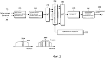
Фиг.2 иллюстрирует обычный передатчик для передачи данных, CSI и HARQ-ACK сигналов по PUSCH.Figure 2 illustrates a conventional transmitter for transmitting data, CSI, and HARQ-ACK signals over PUSCH.
Ссылаясь на фиг.2, кодированные биты 205 CSI и кодированные биты 210 данных мультиплексируют мультиплексором 220. Затем вставляют HARQ-ACK биты путем прокалывания (исключения) битов данных и/или битов CSI посредством модуля 230 прокалывания. Затем посредством модуля 240 DFT выполняют дискретное преобразование Фурье (DFT). Затем посредством преобразования (отображения) поднесущих модулем 250 преобразования поднесущих выбирают RE, соответствующие BW передачи PUSCH от модуля 255 управления. Выполняют обратное быстрое преобразование Фурье (IFFT) посредством модуля 260 IFFT, выполняют вставку CP посредством модуля 270 вставки CP и выполняют операцию «временное окно» посредством фильтра 280, создавая, таким образом, передаваемый сигнал 290.Referring to FIG. 2, encoded
Передача PUCHS предполагается через кластеры смежных RE в соответствии со способом множественного доступа с ортогональным частотным разделением с расширением спектра дискретным преобразованием Фурье (DFT-S-OFDMA) для передачи сигнала через один кластер 295A (также известным как множественный доступ с частотным разделением с одной несущей (SC-FDMA)) или через множество несмежных кластеров 295B.PUCHS transmission is contemplated through adjacent RE clusters in accordance with a discrete Fourier transform (DFT-S-OFDMA) orthogonal frequency division multiple access method for transmitting a signal through a single 295A cluster (also known as single carrier frequency division multiple access ( SC-FDMA)) or through multiple non-adjacent 295B clusters.
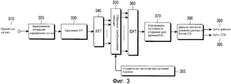
Фиг.3 иллюстрирует обычный приемник для приема посылаемого сигнала, показанного на фиг.2.FIG. 3 illustrates a conventional receiver for receiving a send signal shown in FIG. 2.
Ссылаясь на фиг.3, антенна принимает аналоговый радиочастотный (RF) сигнал и после модулей дальнейшей обработки (таких как фильтры, усилители, частотные преобразователи с понижением частоты, и аналогово-цифровые преобразователи), которые не показаны для краткости, принятый цифровой сигнал 310 фильтруют фильтром 320 и удаляют CP посредством модуля 330 удаления CP. Затем принимающий модуль применяет быстрое преобразование Фурье (FFT) посредством модуля 340 FFT, под управлением модуля 355 управления, с помощью модуля 350 обратного преобразования поднесущих выбирает RE, использованные передатчиком посредством обратного преобразования поднесущих, после чего модуль 360 обратного DFT (IDFT) применяет IDFT, извлекающий модуль 370 извлекает биты HARQ-ACK, а демультиплексирующий модуль 380 демультиплексирует биты 390 данных и биты 395 CSI.Referring to FIG. 3, an antenna receives an analog radio frequency (RF) signal and, after further processing modules (such as filters, amplifiers, frequency down converters, and analog-to-digital converters), which are not shown for brevity, the received
Предполагается, что передача RS осуществляется с использованием последовательности с постоянной амплитудой и нулевой автокорреляцией (CAZAC). Пример CAZAC-последовательностей показан в Уравнении (1).It is assumed that RS transmission is performed using a constant amplitude sequence with zero autocorrelation (CAZAC). An example of CAZAC sequences is shown in Equation (1).
![]()
![]()
![]()
![]()
В Уравнении (1) L является длиной CAZAC-последовательности, n является индексом элемента последовательности n={0,1, …, L-1}, а k является индексом последовательности. Если L является простым числом, то имеется L-1 определенных последовательностей, определенных как k диапазонов в {0, 1, …, L-1}.In Equation (1), L is the length of the CAZAC sequence, n is the index of the sequence element n = {0,1, ..., L-1}, and k is the index of the sequence. If L is a prime, then there are L-1 defined sequences defined as k ranges in {0, 1, ..., L-1}.
Для четного числа RE последовательности с четной длиной, основанные на CAZAC, могут быть созданы, например, посредством усечения или расширения CAZAC-последовательности.For an even number of REs, even-length sequences based on CAZAC can be created, for example, by truncating or expanding the CAZAC sequence.
Ортогональное мультиплексирование CAZAC-последовательностей может быть достигнуто посредством применения разных циклических сдвигов (CS) к одной и той же CAZAC-последовательности.Orthogonal multiplexing of CAZAC sequences can be achieved by applying different cyclic shifts (CS) to the same CAZAC sequence.
Для передачи HARQ-ACK или RI по PUSCH, UE определяет соответствующее число кодированных символов Q', как показано в уравнении (2).To transmit a HARQ-ACK or RI over PUSCH, the UE determines the corresponding number of encoded symbols Q ', as shown in equation (2).

![]()
![]()
В уравнении (2) O является числом битов информации HARQ-ACK или битов информации RI, ![]()
![]()
![]()
![]()
![]()
![]()
Кодовая скорость данных определена, как показано в уравнении (3)The data code rate is determined as shown in equation (3)
![]()
![]()
![]()
![]()
В уравнении (3) C является общим числом кодовых блоков данных, а Kr является числом битов для кодового блока номер r. Максимальное число HARQ-ACK или RI RE ограничено RE из 4 DFT-S-OFDM символов ![]()
![]()
Когда UE принимает один TB, HARQ-ACK включает в себя 1 бит, который кодируют как бинарную "1", если TB корректно принят (положительное квитирование или ACK), или как бинарный "0", если TB принят некорректно (негативное квитирование или NACK).When the UE receives one TB, the HARQ-ACK includes 1 bit, which is encoded as binary "1" if TB is correctly received (positive acknowledgment or ACK), or as binary "0" if TB is received incorrectly (negative acknowledgment or NACK )
Когда UE принимает два TB, HARQ-ACK включает в себя 2 бита ![]()
![]()
![]()
![]()
![]()
![]()
![]()
![]()
Кодирование для 1 бита и 2 битов HARQ-ACKTable 1
Encoding for 1 bit and 2 bits HARQ-ACK
![]()
![]()
![]()
![]()
![]()
![]()
![]()
![]()
![]()
![]()
![]()
![]()
![]()
![]()
![]()
![]()
![]()
![]()
![]()
![]()
![]()
![]()
![]()
![]()
![]()
![]()
![]()
![]()
![]()
![]()
![]()
![]()
![]()
![]()
![]()
![]()
![]()
![]()
![]()
![]()
![]()
![]()
Для CQI/PMI мультиплексирования в PUSCH, UE ![]()
![]()

![]()
![]()
В уравнении (4) O является числом бит информации CQI/PMI, L является числом бит CRC, заданным ![]()
![]()
Для канального кодирования CQI/PMI используют сверточный код, если O>11 бит, и используют (32, O) блочный код Рида-Мюллера, если O≤11бит. Кодовые слова данного (32, O) блочного кода являются линейными комбинациями 11 последовательностей базисов, обозначенных как ![]()
![]()
![]()
![]()
![]()
![]()
![]()
![]()
![]()
![]()
Выходную последовательность ![]()
![]()
![]()
![]()

Среди UCI HARQ-ACK имеют наивысшие требования к надежности, и соответствующие RE расположены следом за RS в каждом временном слоте с тем, чтобы получить наиболее точную оценку канала для их демодуляции. При отсутствии передачи CQI/PMI, RI располагают в символах после HARK-ACK, в то время как при передаче CQI/PMI равномерно мультиплексируют по всему подкадру.Among UCIs, HARQ-ACKs have the highest reliability requirements, and the corresponding REs are located next to the RS in each time slot in order to obtain the most accurate channel estimate for their demodulation. In the absence of CQI / PMI transmission, RIs are located in characters after the HARK-ACK, while in CQI / PMI transmission, they are uniformly multiplexed throughout the subframe.
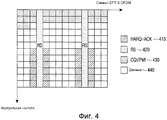
Фиг.4 иллюстрирует обычное мультиплексирование UCI в подкадре PUSCH.4 illustrates conventional UCI multiplexing in a PUSCH subframe.
Ссылаясь на фиг.4, биты 410 HARQ-ACK расположены следом за RS 420 в каждом временном слоте подкадра PUSCH. Биты 430 CQI/PMI мультиплексированы по всем DFT-S-OFDM-символам, а оставшаяся часть подкадра переносит передачу битов 440 данных. Поскольку мультиплексирование осуществляют до DFT, для расположения UCI используют размеры виртуальной частоты.Referring to FIG. 4, HARQ-
Для передатчика UE, имеющего более чем одну антенну, разнесение передачи (TxD) может улучшить надежность принятого сигнала, обеспечивая пространственное разнесение.For a UE transmitter having more than one antenna, transmit diversity (TxD) can improve the reliability of a received signal by providing spatial diversity.
Примером способа TxD является пространственно-временное блочное кодирование (STBC). При STBC, если первая антенна передает символы ![]()
![]()
![]()
![]()
![]()

![]()
![]()
![]()
![]()
![]()
С целью увеличения поддерживаемых скоростей передачи данных рассматривается агрегация множества составляющих несущих (CC), как в DL, так и в UL, для обеспечения больших рабочих BW. Например, для поддержания передачи в пределах 60 МГц, может быть использована агрегация трех 20 МГц CC.In order to increase the supported data rates, aggregation of a plurality of component carriers (CCs) is considered, in both DL and UL, to provide large operational BWs. For example, to maintain transmission within 60 MHz, aggregation of three 20 MHz CCs may be used.
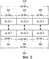
Фиг.5 иллюстрирует принцип обычной агрегации несущих (CA).Figure 5 illustrates the principle of conventional carrier aggregation (CA).
Ссылаясь на фиг.5, рабочая DL BW в 60 МГц 510 построена посредством агрегации 3 (смежных, для простоты) DL CC 521, 522, и 523, каждая из которых имеет BW в 20 МГц. Точно так же рабочая UL BW в 60 МГц 530 построена посредством агрегации 3 UL CC 541, 544, и 543, каждая из которых имеет BW в 20 МГц. Для простоты в примере, показанном на фиг.5, каждая из DL CC 521, 522, и 523 уникально отображается на UL CC (симметричная CA), но также является возможным отобразить на одиночную UL CC более чем одну DL CC или отобразить на одиночную DL CC более чем одну UL CC (ассиметричная CA, не показана для краткости). Линия связи между DL CC и UL CC обычно зависит от UE.Referring to FIG. 5, a working DL BW at 60
Node B конфигурирует CC для UE, используя сигнализацию RRC. Принимая во внимание передачу разных TB в каждом из множества DL CC 521, 522, и 523, в UL будет передаваться множество битов HARQ-ACK.Node B configures the CC for the UE using RRC signaling. Given the transmission of different TBs in each of the plurality of
Для одновременности передач HARQ-ACK и PUSCH прямым расширением обычной работы является включение битов HARQ-ACK для TB, принятого на DL CC, в PUSCH связанного UL CC. Однако на практике не все UL CC могут иметь передачи PUSCH в том же самом подкадре. Таким образом, любое исполнение, поддерживающее передачу по PUSCH битов HARQ-ACK, соответствующих принятию TB на множестве DL CC, должно учитывать случай только с единственным PUSCH. Это также применимо к любому виду UCI (не именно к HARQ-ACK). Предполагается, что передача PUCCH имеет место в одиночной UL CC, которая будет далее именоваться первичной CC UL.For simultaneous HARQ-ACK and PUSCH transmissions, a direct extension of normal operation is the inclusion of HARQ-ACK bits for TB received on the DL CC in the PUSCH of the linked UL CC. However, in practice, not all UL CCs may have PUSCH transmissions in the same subframe. Thus, any design that supports PUSCH transmission of HARQ-ACK bits corresponding to the adoption of TB on a plurality of DL CCs should only consider the case with a single PUSCH. This also applies to any kind of UCI (not specifically to HARQ-ACK). It is assumed that the PUCCH transmission takes place in a single UL CC, which will hereinafter be referred to as primary UL CC.
Для UCI передачи по PUSCH необходимо поддерживать TxD (если UE имеет несколько передающих антенн), особенно для HARQ-ACK, требующих высокую надежность, которая может быть сложно достижима без существенного увеличения требуемых ресурсов PUSCH, особенно для большой нагрузки HARQ-ACK (такой как, например, 10 бит HARQ-ACK, соответствующих получению TB в 5 DL CC, при 2 TB на DL CC.For UCI transmission over PUSCH, it is necessary to support TxD (if the UE has several transmit antennas), especially for HARQ-ACKs that require high reliability, which can be difficult to achieve without significantly increasing the required PUSCH resources, especially for a large HARQ-ACK load (such as, for example, 10 HARQ-ACK bits corresponding to receiving TB in 5 DL CC, at 2 TB per DL CC.
Таким образом, существует необходимость в поддержке передачи информации HARQ-ACK по PUSCH в ответ на прием по меньшей мере одного TB от UE, выполненного с возможностью CA в DL системы связи.Thus, there is a need to support transmitting HARQ-ACK information over a PUSCH in response to receiving at least one TB from a UE configured with CA capability in a DL communication system.
Существует другая необходимость в определении размеров ресурсов PUSCH, используемых для мультиплексирования HARQ-ACK в зависимости от способа кодирования HARQ-ACK с целью улучшения надежности приема HARQ-ACK.There is another need to determine the size of the PUSCH resources used for HARQ-ACK multiplexing depending on the HARQ-ACK encoding method in order to improve the reliability of the HARQ-ACK reception.
Существует другая необходимость в выборе PUSCH для передачи UCI для множества одновременных передач PUSCH.There is another need to select a PUSCH for UCI transmission for multiple simultaneous PUSCH transmissions.
Существует другая необходимость в поддержке TxD для передачи HARQ-ACK по PUSCH.There is another need for TxD support for transmitting HARQ-ACK over PUSCH.
СУЩНОСТЬ ИЗОБРЕТЕНИЯSUMMARY OF THE INVENTION
Целью отдельных вариантов осуществления данного изобретения является решить, смягчить или избежать, хотя бы частично, по меньшей мере одну из проблем и/или недостатков, относящихся к предшествующему уровню техники.The aim of individual embodiments of the present invention is to solve, mitigate or avoid, at least partially, at least one of the problems and / or disadvantages related to the prior art.
Соответственно, настоящее изобретение было призвано решить, по меньшей мере, вышеизложенные ограничения и проблемы в предшествующем уровне техники, и данное изобретение предоставляет способы и устройства для UE передавать сигналы ACK, ассоциированные с HARQ-процессами, то есть сигналы HARQ-ACK, в ответ на прием TB, когда UE сконфигурировано из Node B с множеством CC в DL системы связи, таким образом улучшая надежность приема информации HARQ-ACK, закодированной в PUSCH, выбирать PUSCH среди множества PUSCH для мультиплексирования UCI и применять разнесение передачи HARQ-ACK в PUSCH.Accordingly, the present invention was intended to solve at least the foregoing limitations and problems in the prior art, and the present invention provides methods and devices for a UE to transmit ACK signals associated with HARQ processes, i.e., HARQ-ACK signals, in response to receive TB when a UE is configured from Node B with multiple CCs to a DL communication system, thereby improving the reliability of receiving HARQ-ACK information encoded in a PUSCH, select a PUSCH among a plurality of PUSCHs for UCI multiplexing and apply HA transmit diversity RQ-ACK in PUSCH.
В соответствии с аспектом настоящего изобретения предоставлен способ для пользовательского оборудования (UE) передачи к базовой станции информации квитирования в ответ на прием по меньшей мере одного транспортного блока (TB) по меньшей мере на одной назначенной несущей среди N назначенных несущих, причем для каждой назначенной несущей базовая станция назначает для UE соответствующий режим передачи (TM), определяющий максимальное число TB, которые UE может принять в физическом совместно используемом канале нисходящей линии связи (PDSCH) при передаче базовой станцией на соответствующей назначенной несущей, причем информация квитирования передается (мультиплексируется) совместно с информацией данных в физическом совместно используемом канале восходящей линии связи (PUSCH). Способ включает в себя создание посредством UE N+M битов квитирования; упорядочивание посредством UE упомянутых N+M битов квитирования в кодовом слове в соответствии с порядком назначенных несущих; и кодирование и передачу кодового слова. M является числом назначенных несущих, на которых UE назначен TM, позволяющий прием не более чем 2 TB, а N-M является числом назначенных несущих, на которых устройству UE назначен TM, позволяющий прием 1 TB.According to an aspect of the present invention, there is provided a method for a user equipment (UE) to transmit acknowledgment information to a base station in response to receiving at least one transport block (TB) on at least one assigned carrier among N assigned carriers, for each assigned carrier the base station assigns a corresponding transmission mode (TM) to the UE defining the maximum number of TBs that the UE can receive on the physical downlink shared channel (PDSCH) when ache base station corresponding to the designated carrier, wherein the acknowledgment information is transmitted (multiplexed) together with data information in a physical uplink shared channel used (PUSCH). The method includes generating, by the UE, N + M acknowledgment bits; the ordering by the UE of said N + M acknowledgment bits in the codeword in accordance with the order of the assigned carriers; and coding and transmission of a codeword. M is the number of assigned carriers on which the UE is assigned TM, allowing reception of no more than 2 TB, and N-M is the number of assigned carriers on which the UE is assigned TM, allowing reception of 1 TB.
В соответствии с другим аспектом настоящего изобретения предоставлен способ для улучшения надежности приема управляющей информации в системе связи, причем пользовательское оборудование (UE) кодирует управляющую информацию, используя код, управляющую информацию передают совместно с информацией данных в физический совместно используемый канал восходящей линии связи (PUSCH), номинальную кодовую скорость для управляющей информации определяют из модуляции и кодовой скорости информации данных. Способ включает в себя определение, является ли номинальная кодовая скорость для управляющей информации выше, чем максимальная кодовая скорость; установку кодовой скорости для управляющей информации равной номинальной кодовой скорости, когда номинальная кодовая скорость для управляющей информации не выше, чем максимальная кодовая скорость; установку кодовой скорости для управляющей информации, равной максимальной кодовой скорости, когда номинальная кодовая скорость для управляющей информации выше, чем максимальная кодовая скорость; и передачу управляющей информации, используя установленную кодовую скорость.In accordance with another aspect of the present invention, there is provided a method for improving the reliability of receiving control information in a communication system, wherein a user equipment (UE) encodes control information using a code, control information is transmitted together with data information to a physical uplink shared channel (PUSCH) , the nominal code rate for the control information is determined from the modulation and code rate of the data information. The method includes determining whether the nominal code rate for the control information is higher than the maximum code rate; setting the code rate for the control information equal to the nominal code rate when the nominal code rate for the control information is not higher than the maximum code rate; setting the code rate for the control information equal to the maximum code rate when the nominal code rate for the control information is higher than the maximum code rate; and transmitting control information using the set code rate.
В соответствии с другим аспектом настоящего изобретения предоставлен способ для пользовательского оборудования (UE) выбирать одиночный PUSCH для передачи управляющей информации в системе связи, где базовой станцией для UE запланирована передача информации данных по некоторому числу несущих, используя соответствующий физический совместно используемый канал восходящей линии связи (PUSCH) на каждой из данных несущих, причем UE также передает управляющую информацию. Способ включает в себя вычисление показателя для каждого PUSCH в каждой из данных несущих; выбор PUSCH для передачи управляющей информации в соответствии с вычисленными показателями; и передачу информации данных и управляющей информации в выбранный PUSCH.In accordance with another aspect of the present invention, there is provided a method for a user equipment (UE) to select a single PUSCH for transmitting control information in a communication system where the base station for the UE is scheduled to transmit data information on a number of carriers using an appropriate physical uplink shared channel ( PUSCH) on each of these carriers, wherein the UE also transmits control information. The method includes calculating a metric for each PUSCH in each of these carriers; the selection of PUSCH for transmitting control information in accordance with the calculated indicators; and transmitting data and control information to the selected PUSCH.
В соответствии с другим аспектом настоящего изобретения предоставлен способ для пользовательского оборудования (UE) выбирать одиночный физический совместно используемый канал восходящей линии связи (PUSCH) для передачи управляющей информации в системе связи, причем UE использует ресурсы на первой несущей, когда оно передает только управляющую информацию и запланировано базовой станцией передавать информацию данных по некоторому числу U несущих, используя соответствующие PUSCH в каждой из данных U несущих. Способ включает в себя выбор PUSCH на первой несущей, если она является одной из этих U несущих; выбор PUSCH на второй несущей, причем вторую несущую определяют по порядку несущих, сконфигурированному базовой станцией, если первая несущая не является одной из U несущих; и передачу управляющей информации по выбранному PUSCH.In accordance with another aspect of the present invention, there is provided a method for a user equipment (UE) to select a single physical uplink shared channel (PUSCH) for transmitting control information in a communication system, wherein the UE uses resources on the first carrier when it transmits only control information and it is planned by the base station to transmit data information on a number of U carriers using the corresponding PUSCH in each of the U carrier data. The method includes selecting a PUSCH on a first carrier if it is one of these U carriers; selecting a PUSCH on the second carrier, the second carrier being determined in the order of carriers configured by the base station if the first carrier is not one of the U carriers; and transmitting control information on the selected PUSCH.
В соответствии с другим аспектом настоящего изобретения предоставлено устройство пользовательского оборудования (UE) для передачи информации квитирования, причем устройству UE базовой станцией назначено некоторое число несущих N и режим передачи (TM) для каждой несущей, причем TM определяет максимальное число транспортных блоков (TB), которые устройство UE может принять по соответствующему физическому совместно используемому каналу нисходящей линии связи (PDSCH), передаваемых базовой станцией на назначенной несущей, причем информация квитирования является ответом на прием по меньшей мере одного TB на по меньшей мере одной назначенной несущей и передается совместно с информацией данных по физическому совместно используемому каналу восходящей линии связи (PUSCH). Устройство включает в себя генератор для создания N+M битов квитирования; модуль расстановки для упорядочивания N+M битов квитирования в кодовое слово в соответствии с порядком назначенных несущих; кодировщик для кодирования кодового слова из N+M битов квитирования; и передатчик для передачи информации квитирования и информации данных. M является числом назначенных несущих, которые назначены устройству UE с TM, позволяющим прием не более чем 2 TB, а N-M является числом назначенных несущих, которые назначены устройству UE с TM, позволяющим прием 1 TB.In accordance with another aspect of the present invention, there is provided a user equipment (UE) device for transmitting acknowledgment information, wherein a number of N carriers and a transmission mode (TM) for each carrier are assigned to a UE by a base station, wherein TM determines a maximum number of transport blocks (TB), which the UE may receive on the corresponding physical downlink shared channel (PDSCH) transmitted by the base station on the designated carrier, the acknowledgment information anija is a response to receiving at least one TB for the at least one assigned carrier and is transmitted together with the data information on the physical shared uplink channel (PUSCH). The device includes a generator for generating N + M acknowledgment bits; an arrangement module for arranging N + M acknowledgment bits into a codeword in accordance with the order of assigned carriers; an encoder for encoding a codeword of N + M acknowledgment bits; and a transmitter for transmitting acknowledgment information and data information. M is the number of assigned carriers that are assigned to a UE with a TM capable of receiving no more than 2 TB, and N-M is the number of assigned carriers that are assigned to a UE with a TM that allows receiving 1 TB.
В соответствии с другим аспектом настоящего изобретения предоставлено устройство пользовательского оборудования (UE) для передачи управляющей информации и информации данных на одной несущей, причем устройству UE базовой станцией назначены ресурсы на первой несущей для передачи только управляющей информации, и базовой станцией назначена передача информации данных в определенном числе U несущих с использованием соответствующих физических совместно используемых каналов восходящей линии связи (PUSCH) на каждой из U несущих. Устройство включает в себя селектор для выбора PUSCH на первой несущей, если несущая является одной из U несущих, или для выбора PUSCH на второй несущей, если первая несущая не является одной из U несущих, причем вторую несущую определяют в соответствии с порядком несущих, сконфигурированным базовой станцией; и передатчик для передачи информации данных и управляющей информации по выбранному PUSCH.In accordance with another aspect of the present invention, there is provided a user equipment (UE) device for transmitting control information and data information on a single carrier, wherein resources on the first carrier are assigned to the UE by the base station for transmitting only control information, and the data station is assigned to the base station to transmit information the number of U carriers using the respective physical uplink shared channels (PUSCH) on each of the U carriers. The device includes a selector for selecting PUSCH on the first carrier if the carrier is one of the U carriers, or for selecting PUSCH on the second carrier if the first carrier is not one of the U carriers, the second carrier being determined according to the order of the carriers configured by the base station and a transmitter for transmitting data information and control information on the selected PUSCH.
КРАТКОЕ ОПИСАНИЕ ЧЕРТЕЖЕЙBRIEF DESCRIPTION OF THE DRAWINGS
Приведенные выше и другие аспекты, признаки и преимущества настоящего изобретения будут более очевидны из нижеследующего подробного описания взятыми вместе с прилагающимися чертежами, на которых:The above and other aspects, features and advantages of the present invention will be more apparent from the following detailed description taken in conjunction with the accompanying drawings, in which:
Фиг.1 является схемой, иллюстрирующей обычную структуру подкадра PUSCH;Figure 1 is a diagram illustrating a conventional PUSCH subframe structure;
Фиг.2 является функциональной схемой, иллюстрирующей обычный передатчик для передачи данных, CSI, и HARQ-ACK сигналов по PUSCH;Figure 2 is a functional diagram illustrating a conventional transmitter for transmitting data, CSI, and HARQ-ACK signals over PUSCH;
Фиг.3 является функциональной схемой, иллюстрирующей обычный приемник для приема данных, CSI и HARQ-ACK сигналов по PUSCH;Figure 3 is a functional diagram illustrating a conventional receiver for receiving data, CSI and HARQ-ACK signals over PUSCH;
Фиг.4 является схемой, иллюстрирующей обычное мультиплексирование UCI и данных по PUSCH;4 is a diagram illustrating conventional multiplexing of UCI and PUSCH data;
Фиг.5 является схемой, иллюстрирующей представление об обычной агрегации несущих;5 is a diagram illustrating a representation of conventional carrier aggregation;
Фиг.6 иллюстрирует создание HARQ-ACK битов квитирования в соответствии с вариантом осуществления настоящего изобретения;6 illustrates the creation of HARQ-ACK acknowledgment bits in accordance with an embodiment of the present invention;
Фиг.7 иллюстрирует HARQ-ACK биты информации в соответствии с вариантом осуществления настоящего изобретения;7 illustrates HARQ-ACK information bits in accordance with an embodiment of the present invention;
Фиг.8 иллюстрирует передачу кодированных HARQ-ACK битов от UE, используя QPSK модуляцию с одним повторением и с двумя повторениями блочного кода в соответствии с вариантом осуществления настоящего изобретения;FIG. 8 illustrates the transmission of HARQ-ACK encoded bits from a UE using QPSK modulation with one repetition and two repetitions of a block code in accordance with an embodiment of the present invention;
Фиг.9 иллюстрирует использование разных частот для передачи в каждом временном слоте подкадра кодированных HARQ-ACK бит от UE для двух повторений блочного кода в соответствии с вариантом осуществления настоящего изобретения;FIG. 9 illustrates the use of different frequencies for transmitting at each time slot a subframe of HARQ-ACK encoded bits from a UE for two repetitions of a block code in accordance with an embodiment of the present invention;
Фиг.10 является блок-схемой, иллюстрирующей способ мультиплексирования разной HARQ-ACK (или RI) информационной нагрузки по PUSCH в соответствии с вариантом осуществления настоящего изобретения;10 is a flowchart illustrating a method of multiplexing different HARQ-ACK (or RI) PUSCH information load in accordance with an embodiment of the present invention;
Фиг.11 иллюстрирует выбор одиночного PUSCH среди множества PUSCH для мультиплексирования UCI согласно показателям, измеренным посредством PUSCH MCS, в соответствии с вариантом осуществления настоящего изобретения;11 illustrates the selection of a single PUSCH among a plurality of PUSCHs for UCI multiplexing according to metrics measured by a PUSCH MCS in accordance with an embodiment of the present invention;
Фиг.12 иллюстрирует вложение "UCI_Multiplexing" IE в DCI формат планирования передачи PUSCH, в соответствии с вариантом осуществления настоящего изобретения; и12 illustrates an embedding of the “UCI_Multiplexing” IE in a DCI PUSCH transmission scheduling format, in accordance with an embodiment of the present invention; and
Фиг.13 является схемой, иллюстрирующей STBC передачи HARQ-ACK по PUSCH, в соответствии с вариантом осуществления настоящего изобретения.13 is a diagram illustrating an STBC of transmitting a HARQ-ACK over a PUSCH in accordance with an embodiment of the present invention.
ПОДРОБНОЕ ОПИСАНИЕ ВАРИАНТОВ ОСУЩЕСТВЛЕНИЯ ИЗОБРЕТЕНИЯDETAILED DESCRIPTION OF EMBODIMENTS OF THE INVENTION
Теперь, в дальнейшем в этом документе, различные варианты осуществления настоящего изобретения будут описаны более полно со ссылкой на прилагающиеся чертежи. Однако данное изобретение может быть осуществлено во многих разных видах и не должно интерпретироваться как ограниченное вариантами изобретения, изложенными в данном документе. Вместо этого, эти варианты осуществления предоставлены с тем, чтобы это описание было полным и законченным и полностью передавало объем настоящего изобретения специалистам в данной области техники.Now, later in this document, various embodiments of the present invention will be described more fully with reference to the accompanying drawings. However, the present invention may be practiced in many different forms and should not be interpreted as limited to the variations of the invention set forth herein. Instead, these embodiments are provided so that this description will be thorough and complete and fully convey the scope of the present invention to those skilled in the art.
Кроме того, хотя варианты осуществления настоящего изобретения будут описаны ниже со ссылкой на систему связи с дуплексной передачей с частотным разделением каналов (FDD), использующей OFDM передачу с расширением спектра DFT, они также применимы к системам связи с дуплексной передачей с временным разделением каналов (TDD) и ко всем передачам с мультиплексированием с разделением частот (FDM), в целом, и к ортогональному частотному разделению каналов с мультиплексированием на одной несущей (SC-FDMA) и OFDM, в частности.In addition, although embodiments of the present invention will be described below with reference to a frequency division duplex (FDD) communication system using DFT spread spectrum OFDM transmission, they are also applicable to time division duplex (TDD) communication systems ) to all transmissions with frequency division multiplexing (FDM) in general, and to orthogonal frequency division multiplexing on a single carrier (SC-FDMA) and OFDM in particular.
В соответствии с вариантом осуществления настоящего изобретения мультиплексирование HARQ-ACK выполняют в одиночном PUSCH в ответ на прием по меньшей мере одного TB от UE, сконфигурированного с множеством DL CC (если однозначно не указано иное).According to an embodiment of the present invention, HARQ-ACK multiplexing is performed in a single PUSCH in response to receiving at least one TB from a UE configured with a plurality of DL CCs (unless expressly stated otherwise).
Все O>2 биты HARQ-ACK предполагается совместно закодировать с использованием одного способа кодирования вместо того, чтобы иметь несколько параллельных передач 1 или 2 HARQ-ACK битов для каждой соответствующей DL CC на отдельных ресурсах. Предполагается, что кодирование О битов HARQ-ACK использует (32, O) блочный код, описанный ранее для CQI/PMI передачи (базисные последовательности могут быть теми же самыми или иными, чем те, что даны в таблице 2). Это позволяет выполнить передачу вплоть до 10 бит HARQ-ACK (учитывая только первые 10 базисных последовательностей). Когда используется пакетирование пространственной области HARQ-ACK, каждый соответствующий бит HARQ-ACK соответствует приему 2 TB (где, если оба TB были корректно приняты, передают ACK, а иначе передают NACK).All O> 2 HARQ-ACK bits are supposed to be coded using one coding method instead of having multiple parallel transmissions of 1 or 2 HARQ-ACK bits for each corresponding DL CC on separate resources. It is assumed that the HARQ-ACK bit coding uses the (32, O) block code previously described for CQI / PMI transmission (the base sequences may be the same or different than those given in Table 2). This allows up to 10 bits of HARQ-ACK to be transmitted (considering only the first 10 basis sequences). When HARQ-ACK spatial domain packing is used, each corresponding HARQ-ACK bit corresponds to receiving 2 TB (where, if both TBs were correctly received, they transmit ACKs, otherwise they transmit NACK).
Поскольку некоторые форматы управляющей информации нисходящей линии связи (DO), которые информируют UE о соответствующих PDSCH-передачах в соответствующих DL CC могут быть неправильно приняты (или потеряны) UE, в соответствии с вариантом осуществления настоящего изобретения, существуют два возможных подхода, убедиться в том, что Node B обнаружит число битов HARQ-ACK, равное числу битов HARQ-ACK, которые передает UE, и что Node B и UE имеют одинаковое понимание о размещении битов HARQ-ACK в соответствующем кодовом слове RM-кода.Since some downlink control information (DO) formats that inform the UE of the respective PDSCH transmissions in the respective DL CCs may be incorrectly received (or lost) by the UE, in accordance with an embodiment of the present invention, there are two possible approaches to verify that Node B will detect the number of HARQ-ACK bits equal to the number of HARQ-ACK bits that the UE transmits, and that Node B and UE have the same understanding of the placement of HARQ-ACK bits in the corresponding RM codeword.
В первом подходе UE использует (32, O) RM блочный код и возвращает число битов HARQ-ACK, определенное из числа ее сконфигурированных DL CC и соответствующе сконфигурированных режимов передачи (TM). TM для каждой DL CC назначают UE посредством сигнализации RRC от Node B, и определяют, может ли UE принять максимум 1 TB или 2 TB на DL CC. Если UE сконфигурировано на DL CC с TM, поддерживающим 2 TB, то UE передает 2 бита HARQ-ACK для этой DL CC, независимо от числа TB (0, 1, или 2) фактически принятых UE в соответствующем DL подкадре. Если UE сконфигурировано на TM, поддерживающий 2 TB в DL CC, то тогда, если соответствующий PDSCH переносит 1 TB (вместо 2 TB), UE показывает некорректный прием для второго TB (NACK) в соответствующей позиции кодового слова HARQ-ACK. Если соответствующий PDSCH не принят, UE показывает некорректный прием для 2 TB (2 NACK) в соответствующих позициях кодового слова HARQ-ACK.In the first approach, the UE uses the (32, O) RM block code and returns the number of HARQ-ACK bits determined from the number of its configured DL CC and the correspondingly configured transmission modes (TM). TM for each DL CC is assigned to the UE by RRC signaling from Node B, and it is determined whether the UE can receive a maximum of 1 TB or 2 TB per DL CC. If the UE is configured on a DL CC with a TM supporting 2 TB, then the UE transmits 2 HARQ-ACK bits for this DL CC, regardless of the number of TB (0, 1, or 2) actually received by the UEs in the corresponding DL subframe. If the UE is configured on a TM supporting 2 TB in DL CC, then if the corresponding PDSCH carries 1 TB (instead of 2 TB), the UE shows incorrect reception for the second TB (NACK) at the corresponding position of the HARQ-ACK codeword. If the corresponding PDSCH is not received, the UE shows an incorrect reception for 2 TB (2 NACK) at the corresponding positions of the HARQ-ACK codeword.
Если UE имеет M1 DL CC и имеется N1≤M1 DL CC, для которых PDSCH может переносить 2 TB (UE сконфигурировано на TM, поддерживающий 2 TB), число битов HARQ-ACK в PUSCH вычисляют как O=2N1+(M1-N1)=M1+N1. Если UE имеет только M1=2 DL CC и имеется N1=0 DL CC со сконфигурированным TB, позволяющим прием максимум 2 TB, то тогда UE передает O=2 бита HARQ-ACK, используя описанный ранее (3, 2) симплексный код. Во всех остальных случаях UE по меньшей мере с 2 сконфигурированными DL CC имеет минимальное число O=3 HARQ-ACK бит и использует (32, O) блочный код RM для переноса их по PUSCH.If the UE has M 1 DL CC and there is N 1 ≤M 1 DL CC for which the PDSCH can carry 2 TB (the UE is configured on a TM supporting 2 TB), the number of HARQ-ACK bits in the PUSCH is calculated as O = 2N 1 + ( M 1 -N 1 ) = M 1 + N 1 . If the UE has only M 1 = 2 DL CC and there is N 1 = 0 DL CC with a configured TB that allows reception of a maximum of 2 TB, then the UE transmits O = 2 bits of the HARQ-ACK using the simplex code described previously (3, 2) . In all other cases, a UE with at least 2 DL CCs configured has a minimum number of O = 3 HARQ-ACK bits and uses a (32, O) block RM code to carry them over PUSCH.
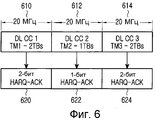
Фиг.6 иллюстрирует первый подход для мультиплексирования HARQ-ACK по PUSCH, в соответствии с вариантом осуществления настоящего изобретения.6 illustrates a first approach for multiplexing a HARQ-ACK over a PUSCH, in accordance with an embodiment of the present invention.
Ссылаясь на фиг.6, UE имеет 3 DL CC, DL CC1 610, DL CC2 612, и DL CC3 614. На DL CC1 610 UE сконфигурировано на TM1, поддерживающий максимум 2 TB, на DL CC2 612 UE сконфигурировано на TM2, поддерживающий максимум 1 TB, и на DL CC3 614 UE сконфигурировано на TM3, поддерживающий максимум 2 TB. UE всегда передает 2-битный HARQ-ACK 620, соответствующий DL CC1 610, 1-битный HARQ-ACK 622, соответствующий DL CC2 612, и 2-битный HARQ-ACK 624, соответствующий DL CC3 614. Во всех случаях передача HARQ-ACK происходит независимо от того, принимает ли UE PDSCH на соответствующих DL CC. Таким образом, UE всегда передает, а Node B всегда принимает 5 битов HARQ-ACK для мультиплексирования HARQ-ACK в PUSCH.Referring to FIG. 6, the UE has 3 DL CC,
Во втором подходе каждый формат DCI, планирующий передачу PUSCH, включает в себя информационный элемент (IE) индикатора назначения нисходящей линии связи (DAI). DAI IE является битовым массивом, обозначающим DL CC в передаче PDSCH. К примеру, полагая, что UE может иметь максимум 5 DL CC, DAI IE состоит из 5 бит. При использовании DAI IE число битов HARQ-ACK не всегда является максимальной соответствующей сконфигурированной DL CC. Также могут применяться различные способы для уменьшения числа битов DAI IE. К примеру, UE может полагать, что оно всегда имеет PDSCH-передачу на DL CC, в этом случае битовый массив не рассматривает эту DL CC. Число битов HARQ-ACK, передаваемых UE по PUSCH, зависит от обозначенного DAI IE максимального числа TB, которые PDSCH может переносить на DL CC.In a second approach, each DCI format scheduling a PUSCH transmission includes a downlink assignment indicator (DAI) information element (IE). DAI IE is a bitmap denoting DL CC in PDSCH transmission. For example, assuming that a UE can have a maximum of 5 DL CC, DAI IE consists of 5 bits. When using DAI IE, the number of HARQ-ACK bits is not always the maximum correspondingly configured DL CC. Various methods may also be used to reduce the number of DAI IE bits. For example, the UE may assume that it always has a PDSCH transmission on DL CC, in which case the bitmap does not consider this DL CC. The number of HARQ-ACK bits transmitted by the UE over the PUSCH depends on the maximum number of TBs designated by the DAI IE that the PDSCH can carry on the DL CC.
Если DAI IE обозначает M2 DL CC (битовый массив имеет M2 битов со значением 1, обозначающим DL CC) и, в этих M2 DL CC имеются N2≤M2 DL CC, для которых PDSCH может переносить 2 TB, то число битов HARQ-ACK равно ![]()
![]()
Аналогично первому подходу, если DAI IE обозначает только M2=1 DL CC или M2=2 DL CC, где оба имеют сконфигурированный TM, ассоциированный с приемом 1 TB (N2=0), то тогда UE передает O=1 или O=2 битов HARQ-ACK, используя соответственно один из двух описанных ранее способов (код с повторениями или (3, 2) симплексный код). Во всех остальных случаях UE имеет минимальное число O=3 бита HARQ-ACK и, когда она переносит их по PUSCH, она использует (32, O) блочный код RM.Similar to the first approach, if DAI IE denotes only M 2 = 1 DL CC or M 2 = 2 DL CC, where both have a configured TM associated with receiving 1 TB (N 2 = 0), then the UE transmits O = 1 or O = 2 bits of HARQ-ACK, using respectively one of the two methods described previously (code with repetitions or (3, 2) simplex code). In all other cases, the UE has a minimum number of O = 3 HARQ-ACK bits and, when it carries them over PUSCH, it uses the (32, O) block code RM.
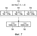
Фиг.7 иллюстрирует биты информации HARQ-ACK в соответствии с вариантом осуществления настоящего изобретения, то есть вариант осуществления второго подхода.7 illustrates HARQ-ACK information bits in accordance with an embodiment of the present invention, that is, an embodiment of the second approach.
Ссылаясь на фиг.7, опорное UE имеет 3 DL CC, DL CC1 720, DL CC2 722, и DL CC3 724. На DL CC1 720 UE сконфигурировано на TM1, поддерживающий максимум 2 TB, на DL CC2 722 UE сконфигурировано на TM2, поддерживающий максимум 1 TB, а на DL CC3 724 UE сконфигурировано на TM3, поддерживающий максимум 2 TB. DAI IE 710 в формате DCI для передачи PUSCH обозначает передачу PDSCH на DL CC1 и DL CC2. UE передает 2 бита 730 HARQ-ACK для DL CC1 720 и 1 бит 732 HARQ-ACK для DL CC2 722. Эта передача HARQ-ACK происходит независимо от того, приняла ли UE фактически PDSCH на DL CC1 или DL CC2 (PDSCH является потерянным, когда является потерянным соответствующий DL SA).Referring to FIG. 7, the reference UE has 3 DL CC,
Порядок битов HARQ-ACK в блочном коде определяют по порядку соответствующих DL CC. Порядок DL CC может быть сконфигурирован посредством Node B через сигнализацию RRC или неявно определен, например, из порядка несущих частот для этих DL CC. То есть DL CC могут быть упорядочены по возрастанию несущей частоты.The order of the HARQ-ACK bits in the block code is determined by the order of the corresponding DL CCs. The DL CC order may be configured by Node B via RRC signaling or implicitly determined, for example, from the carrier frequency order for these DL CCs. That is, DL CCs may be ordered by increasing carrier frequency.
После того как UE определит число O битов HARQ-ACK для передачи, оно применяет (32, O) блочный код, как показано в Таблице 2.After the UE determines the number of O HARQ-ACK bits for transmission, it applies the (32, O) block code, as shown in Table 2.
В соответствии с вариантом осуществления настоящего изобретения с целью достижения требуемой надежности может быть применено повторение кодированных битов HARQ-ACK. К примеру, для модуляции QPSK 32 выходных бита могут быть преобразованы в 16 модулированных символов, которые распределены на блоки по 4 RE в 4 DFT-S-OFDM символах по 2 RS на подкадр. Когда применено множественное повторение кодированных битов HARQ-ACK, RE, используемые для передачи HARQ-ACK, кратны 16.In accordance with an embodiment of the present invention, in order to achieve the desired reliability, repetition of HARQ-ACK encoded bits can be applied. For example, to modulate QPSK, 32 output bits can be converted into 16 modulated symbols, which are distributed into 4 RE blocks in 4 DFT-S-OFDM symbols at 2 RS per subframe. When multiple repetition of the encoded HARQ-ACK bits is applied, the REs used to transmit the HARQ-ACK are multiples of 16.
Фиг.8 иллюстрирует передачу кодированных битов HARQ-ACK для модуляции QPSK с одним повторением и двумя повторениями (32, O) блочного кода. Для простоты, передача других видов UCI не рассматривается.FIG. 8 illustrates the transmission of HARQ-ACK encoded bits for QPSK modulation with one repetition and two repetitions (32, O) of a block code. For simplicity, the transfer of other types of UCI is not considered.
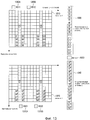
Ссылаясь на фиг.8, PUSCH включает в себя HARQ-ACK RE для первого повторения 810A, HARQ-ACK RE для второго повторения 810B, RS RE 820 и RE 830 данных. Для одного повторения HARQ-ACK RE отображены вокруг RS в группах по 4 RE, 840A и 840B. Для двух повторений HARQ-ACK RE отображены вокруг RS в группах по 4 RE, 850A и 850B для первого повторения и далее - в группах по 4 RE 860A и 860B для второго повторения.Referring to FIG. 8, the PUSCH includes a HARQ-ACK RE for a first repeat 810A, a HARQ-ACK RE for a second repeat 810B, RS RE 820, and data RE 830. For one repetition, HARQ-ACK REs are mapped around RS in groups of 4 REs, 840A and 840B. For two repetitions, HARQ-ACK REs are displayed around RS in groups of 4 RE, 850A, and 850B for the first repetition, and further in groups of 4 REs of 860A and 860B for the second repetition.
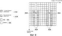
Как показано на фиг.9 для 2 повторений, для нескольких повторений, с целью улучшения разнесения частот и разнесения помех каждого повторения, для передачи в каждом временном слоте могут быть использованы разные частоты.As shown in FIG. 9, for 2 repetitions, for several repetitions, in order to improve frequency diversity and interference diversity of each repetition, different frequencies can be used for transmission in each time slot.
Фиг.9 иллюстрирует использование разных частот для передачи от UE в каждом временном слоте подкадра кодированных битов HARQ-ACK для двух повторений блочного кода в соответствии с вариантом осуществления настоящего изобретения.FIG. 9 illustrates the use of different frequencies for transmission from the UE in each time slot of a subframe of HARQ-ACK encoded bits for two repetitions of a block code in accordance with an embodiment of the present invention.
Ссылаясь на фиг.9, подкадр PUSCH включает в себя HARQ-ACK RE для первого повторения 910A, HARQ-ACK RE для второго повторения 910B, RS RE 920, RE 930 данных. HARQ-ACK RE отображены вокруг RS в группах по 4 RE, где расположение данных RE в первом временном слоте для первого повторения 940A и для второго повторения 940B изменено во втором временном слоте для первого повторения 950A и для второго повторения 950B.Referring to FIG. 9, a PUSCH subframe includes HARQ-ACK RE for a
Для передачи HARQ-ACK по PUSCH UE определяет соответствующее число кодовых символов Q' (номинальную кодовую скорость), как показано в уравнении (5).For transmitting the HARQ-ACK over the PUSCH, the UE determines the corresponding number of code symbols Q '(nominal code rate), as shown in equation (5).

![]()
![]()
Поскольку информационная нагрузка HARQ-ACK фиксирована O битами, число кодовых символов Q' определяет кодовую скорость передачи HARQ-ACK, которая обратно пропорциональна MCS передачи данных, как это задано посредством ![]()
![]()
В качестве альтернативы, с целью упрощения операций кодирования информации на передатчике UE и операций декодирования информации на приемнике Node B и чтобы избежать потерь на прокалывание, ассоциированных с повышением кодовой скорости для блочного кода с укороченной длиной (если ![]()
![]()

В уравнении (6), ![]()
![]()
![]()
![]()
![]()
![]()
![]()
![]()
![]()
![]()
![]()
![]()
![]()
![]()
Поскольку скорость блочного кода зависит от числа передаваемых битов HARQ-ACK, даже если UE всегда передает максимальное число битов HARQ-ACK, соответствующих всем DL CC, для передачи HARQ-ACK разница в надежности приема из-за различия в скорости блочного кода отражается в зависимости от ![]()
![]()
![]()
![]()
![]()
![]()
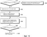
Фиг.10 является функциональной схемой, иллюстрирующей способ мультиплексирования разной информационной нагрузки HARQ-ACK (или RI) (числа битов информации) по PUSCH, в соответствии с вариантом осуществления настоящего изобретения. В частности, фиг.10 иллюстрирует функциональные возможности передатчика UE и приемника Node B при мультиплексировании разной информационной нагрузки HARQ-ACK по PUSCH.10 is a functional diagram illustrating a method of multiplexing different HARQ-ACK (or RI) information load (number of information bits) over a PUSCH in accordance with an embodiment of the present invention. In particular, FIG. 10 illustrates the functionality of a UE transmitter and a Node B receiver when multiplexing different HARQ-ACK information load on a PUSCH.
Ссылаясь на фиг.10, на этапе 1010 определяют, является ли число битов HARQ-ACK O>2. Если число битов HARQ-ACK не O>2, для передачи HARQ-ACK на этапе 1020 используют обычный способ (код с повторением или симплексный код). Однако, если число битов HARQ-ACK O>2, биты HARQ-ACK кодируют с использованием (32, O) RM блочного кода на этапе 1030.Referring to FIG. 10, it is determined in
На этапе 1040, предполагая 2 бита HARQ-ACK на символ модуляции (модуляция QPSK), 32 кодированных бита HARQ-ACK (предполагается, что кодовую скорость уменьшают с ее номинального значения для обеспечения, по меньшей мере, 1 повторения 32 кодированных битов) делят на 4 квадруплета, которые затем, на этапе 1050, располагают в 4 RE в 4 DFT-S-OFDM символах следом за 2 символами RS в подкадре передачи PUSCH. Если условия, определяющие число кодовых символов HARQ-ACK требуют дополнительных повторений на этапе 1060, этап 1050 повторяют, используя дополнительные RE. Однако если дополнительных повторений на этапе 1060 нет, то процесс расположения битов HARQ-ACK по PUSCH завершают на этапе 1070.At 1040, assuming 2 HARQ-ACK bits per modulation symbol (QPSK modulation), 32 HARQ-ACK encoded bits (it is assumed that the code rate is reduced from its nominal value to ensure at least 1 repetition of 32 encoded bits) is divided by 4 quadruplets, which then, at 1050, are arranged in 4 REs in 4 DFT-S-OFDM symbols followed by 2 RS symbols in the PUSCH transmission subframe. If the conditions determining the number of HARQ-ACK code symbols require additional repetitions in
После того как битам HARQ-ACK применили кодирование и распределение ресурсов, как показано на фиг.10, для отправки и приема данных HARQ-ACK битов могут быть использованы такие устройства, как описанные выше относительно фиг.2 и фиг.3. Соответственно, повторное описание не будет предоставлено в настоящем документе.After the HARQ-ACK bits have been used for coding and resource allocation, as shown in FIG. 10, devices such as those described above with respect to FIG. 2 and FIG. 3 can be used to send and receive HARQ-ACK bit data. Accordingly, a duplicate description will not be provided herein.
В соответствии с другим вариантом осуществления настоящего изобретения для мультиплексирования UCI во время одного и того же подкадра на разных UL CCs среди нескольких PUSCH выбирают единственный PUSCH. Рассматривая S передач PUSCH без пространственного мультиплексирования с соответствующими MCS, равными {MCS(1),MCS(2),…,MCS(S)}, первый подход предполагает, что UE выбирает для мультиплексирования UCI передачу PUSCH с наибольшим MCS. Таким образом, UE передает UCI на UL CC s, полученной как ![]()
![]()
Фиг.11 иллюстрирует выбор для мультиплексирования UCI единственного PUSCH среди нескольких PUSCH в соответствии с вариантом осуществления настоящего изобретения.11 illustrates the selection for multiplexing UCI single PUSCH among several PUSCH in accordance with an embodiment of the present invention.
Ссылаясь на фиг.11, опорная UE имеет 3 передачи PUSCH в подкадре на 3 соответствующих UL CC, UL CC1 с модуляцией QPSK и кодовой скоростью r=1/2 1110, UL CC2 с модуляцией QAM16 и кодовой скоростью r=1/2 1120 и UL CC3 с модуляцией QAM16 и кодовой скоростью r=1/3 1130. Поскольку передача PUSCH на UL CC2 имеет наибольший MCS (наибольшую спектральную эффективность), UE мультиплексирует UCI в передачу PUSCH на UL CC2 1140.Referring to FIG. 11, the reference UE has 3 PUSCH transmissions in a subframe on 3 corresponding UL CC, UL CC1 with QPSK modulation and code rate r = 1/2 1110, UL CC2 with QAM16 modulation and code rate r = 1/2 1120 and UL CC3 with QAM16 modulation and code rate r = 1/3 1130. Since the PUSCH transmission on UL CC2 has the highest MCS (highest spectral efficiency), the UE multiplexes the UCI into the PUSCH transmission on
Преимущество выбора только одного PUSCH для мультиплексирования UCI состоит в том, что обеспечивается единственное решение, независимо от числа передач PUSCH, которые может иметь UE в одном подкадре, и это естественно подходит для общего кодирования всех битов HARQ-ACK. Посредством выбора передачи PUSCH с наибольшим MCS достигается наилучшая надежность для передачи UCI, поскольку обычно, чем больше MCS, тем лучше качество линии связи.The advantage of choosing only one PUSCH for UCI multiplexing is that it provides a single solution, regardless of the number of PUSCH transmissions that a UE can have in one subframe, and this is naturally suitable for general coding of all HARQ-ACK bits. By choosing the PUSCH transmission with the highest MCS, the best reliability for UCI transmission is achieved, because usually, the more MCS, the better the quality of the communication line.
Дополнительно, выбор единственного PUSCH минимизирует влияние от ошибочных решений, которые могут возникнуть, если UE пропустит форматы DCI, планирующие передачи PUSCH. Когда Node B и UE имеют разное понимания о выборе PUSCH с набольшим MCS, например из-за того, что UE пропустило формат DCI, планирующий PUSCH с наибольшим MCS, тогда Node B может обнаружить отсутствие подобной передачи и может определить, что это UCI включено в первую передачу PUSCH с наибольшим MCS из обнаруженных Node B. Если несколько передач PUSCH имеют одну и ту же наибольшую MCS, выбранная передача PUSCH может быть на заранее заданной UL CC, например на такой как UL CC с меньшим индексом, учитывая, что эти индексы сконфигурированы UE посредством Node B.Additionally, selecting a single PUSCH minimizes the impact of erroneous decisions that may occur if the UE skips DCI formats scheduling PUSCH transmissions. When Node B and UE have different understandings about choosing PUSCH with the largest MCS, for example, because the UE skipped the DCI format planning the PUSCH with the largest MCS, then Node B can detect the absence of such a transmission and can determine that this UCI is included in the first PUSCH transmission with the highest MCS of the detected Node B. If several PUSCH transmissions have the same highest MCS, the selected PUSCH transmission may be on a predetermined UL CC, for example, such as a UL CC with a lower index, given that these indices are configured UE by Node B.
В соответствии с другим вариантом осуществления изобретения UE выбирает для мультиплексирования UCI передачу PUSCH, минимизируя относительный объем RE данных, которые должны быть заменены посредством RE UCI. Если UE имеет в подкадре S передач PUSCH и соответствующее число RE, требующихся для мультиплексирования UCI, в PUSCH s является O(s), s=1,…,S, то тогда UE может выбрать для мультиплексирования PUSCH, минимизируя коэффициент полезности U(s), как показано в уравнении (7).According to another embodiment of the invention, the UE selects PUSCH transmission for multiplexing the UCI, minimizing the relative amount of RE data to be replaced by the UCI RE. If the UE has PUSCH transmissions in subframe S and the corresponding number of REs required for UCI multiplexing, in PUSCH s is O (s), s = 1, ..., S, then the UE can choose PUSCH for multiplexing, minimizing the U (s ), as shown in equation (7).
![]()
![]()
![]()
![]()
В уравнении (7), ![]()
![]()
![]()
![]()
В соответствии с другим вариантом осуществления изобретения Node B может динамически выбирать PUSCH для мультиплексирования UCI посредством включения 1-битного IE в формат DCI, планирующий каждую передачу PUSCH для обозначения того, следует или нет мультиплексировать UCI в соответствующий PUSCH. Когда формат DCI, обозначающий PUSCH для мультиплексирования UCI, потерян UE, UE может вернуться к выбору PUSCH с наибольшим MCS или к минимизирующему относительный объем служебных сигналов UCI. То же самое применимо при отсутствии формата DCI, ассоциированного с передачей PUSCH, например, в частности, для синхронных неадаптивных повторных передач HARQ или полупостоянных передач PUSCH.According to another embodiment of the invention, Node B can dynamically select a PUSCH for UCI multiplexing by including a 1-bit IE in DCI format scheduling each PUSCH transmission to indicate whether or not to multiplex the UCI into the corresponding PUSCH. When the DCI format denoting the PUSCH for UCI multiplexing is lost by the UE, the UE may return to selecting the PUSCH with the largest MCS or minimizing the relative amount of UCI overhead. The same applies if there is no DCI format associated with the PUSCH transmission, for example, in particular for synchronous non-adaptive HARQ retransmissions or semi-persistent PUSCH transmissions.
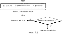
Фиг.12 иллюстрирует включение "UCI_Multiplexing" IE в формат DCI планирования передачи PUSCH.12 illustrates the inclusion of "UCI_Multiplexing" IEs in the DCI format of PUSCH transmission scheduling.
Ссылаясь на фиг.12, для передачи 1210 PUSCH, "UCI_Multiplexing" IE 1220 в ассоциированном формате DCI указывает, следует ли UE включать передачу ее UCI по PUSCH 1230 или нет 1240.Referring to FIG. 12, for
Вместо явного введения IE для обозначения того, следует ли UE включать UCI в ее передачу PUSCH, для неявного выполнения функциональной возможности может быть использован существующий IE в формате DCI планирования передачи PUSCH. К примеру, предполагается, что формат DCI содержит IE индикатора циклического сдвига (CSI) для информирования UE о применении циклического сдвига (CS) к передаче RS по PUSCH. Значение CSI может быть зарезервировано так, что, будучи сообщенным в формате DCI, оно также обозначало добавление UCI по PUSCH. Значения других существующих IE формата DCI или их сочетания также могут быть использованы для тех же самых целей. Снова можно применить процесс на фиг.12 (дополнительная иллюстрация для краткости опущена), за исключением того, что вместо проверки значения "UCI Multiplexing" IE UE проверяет, имеют ли существующие CSI IE заданное значение, и если да, то включает UCI в передачу PUSCH.Instead of explicitly introducing IE to indicate whether the UE should include the UCI in its PUSCH transmission, an existing IE in the DCI format of the PUSCH transmission scheduling may be used to implicitly perform the functionality. For example, it is assumed that the DCI format contains a cyclic shift indicator (CSI) IE to inform the UE of the application of the cyclic shift (CS) to the RS transmission on PUSCH. The CSI value can be reserved so that, when reported in DCI format, it also indicates the addition of UCI over PUSCH. Values of other existing DCI IEs or combinations thereof may also be used for the same purpose. Again, the process of FIG. 12 can be applied (omitted for brevity for the sake of brevity), except that instead of checking the “UCI Multiplexing” value, the IE UE checks to see if the existing CSI IEs have a given value, and if so, include the UCI in the PUSCH transmission .
В соответствии с другим вариантом осуществления изобретения в отсутствие какой бы то ни было передачи PUSCH та же самая UL CC (Первичная UL CC) всегда используется UE для передачи UCI в PUCCH. Первичная UL CC (UL PCC) также может быть UL CC по умолчанию для мультиплексирования UCI по PUSCH, когда передача PUSCH существует на UL PCC. В противном случае UE может вернуться к другим способам для выбора PUSCH (например, используя один из ранее описанных показателей или используя заранее заданный порядок на основе индексов UL CC, как было описано выше). Преимущество использования передачи PUSCH (когда она существует) на UL PCC для переноса UCI имеет место, если UE выполнено с возможностью передавать некоторую часть UCI (такую как CQI/PMI) по PUCCH, а некоторую другую часть UCI (такую как HARQ-ACK) по PUSCH. Посредством использования передач на одной и той же UL CC (UL PCC) для переноса UCI по PUSCH и PUCCH минимизируется влияние межмодуляционных составляющих и возможного требования по снижению мощности передачи UCI.According to another embodiment of the invention, in the absence of any PUSCH transmission, the same UL CC (Primary UL CC) is always used by the UE to transmit the UCI to the PUCCH. Primary UL CC (UL PCC) can also be the default UL CC for PUSCH UCI multiplexing when PUSCH transmission exists on the UL PCC. Otherwise, the UE may return to other methods for selecting the PUSCH (for example, using one of the previously described metrics or using a predefined order based on UL CC indices, as described above). The advantage of using PUSCH transmission (when it exists) on the UL PCC to transfer the UCI is if the UE is configured to transmit some part of the UCI (such as CQI / PMI) over the PUCCH and some other part of the UCI (such as the HARQ-ACK) PUSCH. By using transmissions on the same UL CC (UL PCC) to transfer UCI over PUSCH and PUCCH, the influence of the intermodulation components and the possible requirement to reduce the transmission power of the UCI are minimized.
В соответствии с вариантом осуществления настоящего изобретения к передаче UCI по PUSCH применяют TxD.In accordance with an embodiment of the present invention, TxD is applied to UCI transmission over PUSCH.
Фиг.13 иллюстрирует STBC передачи HARQ-ACK по PUSCH в соответствии с вариантом осуществления настоящего изобретения.13 illustrates a STBC transmission of HARQ-ACK over a PUSCH in accordance with an embodiment of the present invention.
Ссылаясь на фиг.13, как правило, подразумевают, что число RE HARQ-ACK является четным, в частности предполагая модуляцию типа QPSK и (32, O) блочный код, число RE HARQ-ACK является кратным 16 (=32/2). Первая антенна UE передает структуру 1310, а вторая антенна UE передает структуру 1320. UE применяет STBC для передачи модулированных символов 1330 HARQ-ACK с первой антенны, и применяет STBC для передачи модулированных символов 1340 HARQ-ACK со второй антенны. UE может применять или не применять STBC для передачи данных 1350.Referring to FIG. 13, it is generally understood that the HARQ-ACK RE number is even, in particular assuming QPSK type modulation and (32, O) block code, the HARQ-ACK RE number is a multiple of 16 (= 32/2). The first UE antenna transmits
Передача RS в каждом из двух временных слотов с первой антенны, RS11 1360A и RS12 1360B, являются ортогональными передаче RS в каждом из двух временных слотов со второй антенны, RS21 1370A и RS22 1370B. К примеру, RS11 1360A и RS21 1370A могут использовать разные CS. RS12 1360B и RS22 1370B также могут использовать разные CS. UE может получить CS для RS11 1360A из CSI IE в формате DCI или посредством сигнализации RRC от Node B. CS для RS21 1370A может быть косвенно определен из CS для RS11 1360A (к примеру, CS для RS21 1370A может быть неким с наибольшим расстоянием от CS для RS11).The RS transmission in each of the two time slots from the first antenna,
Устройство UE для передачи с первой антенны показано на фиг.2 Устройство для передачи со второй антенны также показано на фиг.2, за исключением того, что модулированные символы HARQ-ACK, такие как на фиг.13.A UE for transmitting from a first antenna is shown in FIG. 2 A device for transmitting from a second antenna is also shown in FIG. 2, except that the HARQ-ACK modulated symbols, such as in FIG. 13.
Устройство приемника Node B показано на фиг.3 (для битов HARQ-ACK) за исключением применения обработки приема STBC, как описано выше. Таким образом, для опорной антенны приемника Node B, если hj является оценкой состояния канала для сигнала, передаваемого от j-той антенны UE, j=1,2, а yk является сигналом, принятым в k-том символе DFT-S-OFDM, k=1,2, решение для пары символов HARQ-ACK ![]()
![]()
![]()
![]()
![]()
![]()
STBC TxD может применяться или не применяться к другим видам UCI или информации данных. К примеру, STBC TxD можно применить к RI, как для HARQ-ACK, поскольку RI всегда передают в четном числе символов DFT-S-OFDM. Однако STBC TxD можно не применять для CQI или для информации данных, про которые, из-за возможной передачи SRS, обычно нельзя с уверенностью сказать, что они существуют в четном числе символов DFT-S-OFDM.STBC TxD may or may not apply to other types of UCI or data information. For example, STBC TxD can be applied to RIs as for HARQ-ACKs, since RIs always transmit in an even number of DFT-S-OFDM symbols. However, STBC TxD can not be used for CQI or for information of data about which, due to the possible transmission of SRS, it is usually impossible to say with certainty that they exist in an even number of DFT-S-OFDM symbols.
Число ресурсов (кодовых символов), используемых для передачи вида UCI по PUSCH, также может зависеть от использования TxD. К примеру, поскольку TxD обычно улучшает надежность приема соответствующей информации, требуется меньше ресурсов для достижения требуемой надежности для данного вида UCI. Для определения ресурсов UCI по PUSCH, когда к передаче UCI применен конкретный TxD-способ, например STBC, для соответствующего вида UCI может быть применен разный набор значений ![]()
![]()
![]()
![]()
![]()
![]()
![]()
![]()
![]()
![]()
![]()
![]()
В то время как настоящее изобретение было показано и описано со ссылкой на некоторые варианты его осуществления, специалистам в данной области техники будет понятно, что в нем могут быть сделаны различные изменения в форме и деталях, не выходя из объема настоящего изобретения, как определено в прилагаемой формуле изобретения и ее эквивалентах.While the present invention has been shown and described with reference to some embodiments thereof, those skilled in the art will understand that various changes in form and detail can be made therein without departing from the scope of the present invention as defined in the attached the claims and its equivalents.
Следует понимать, что варианты осуществления настоящего изобретения могут быть реализованы в виде аппаратного обеспечения, программного обеспечения или сочетания аппаратного и программного обеспечений. Любое подобное программное обеспечение может быть сохранено в запоминающем устройстве постоянного или непостоянного вида, к примеру таком, как устройство хранения, подобное ПЗУ, стираемому или перезаписываемому, или в разновидности памяти, такой как, к примеру, ОЗУ, микросхема памяти, устройства или интегральные схемы или оптически- или магнитно-читаемый носитель, такой как, к примеру, CD, DVD, магнитный диск или магнитная лента и тому подобное. Следует понимать, что данные устройства хранения и среды хранения являются вариантами осуществления машиночитаемого хранилища, которое пригодно для хранения программы или программ, содержащих команды, которые при исполнении реализуют варианты осуществления настоящего изобретения. Соответственно, варианты осуществления предоставляют программный код для реализации системы или способа, заявленного в любом из пунктов формулы изобретения данного документа, а машиночитаемое запоминающее устройство хранит подобную программу. Более того, подобные программы могут быть переданы электронным способом через любой носитель, например сигнал связи, передаваемый через проводное или беспроводное соединение, и варианты осуществления, подходящие для осуществления того же самого.It should be understood that embodiments of the present invention may be implemented as hardware, software, or a combination of hardware and software. Any such software can be stored in a permanent or non-permanent storage device, for example, such as a storage device, such as ROM, erasable or rewritable, or in a kind of memory, such as, for example, RAM, a memory chip, device or integrated circuit or an optical or magnetic readable medium, such as, for example, CD, DVD, magnetic disk or magnetic tape and the like. It should be understood that these storage devices and storage media are embodiments of computer-readable storage that is suitable for storing programs or programs containing instructions that, when executed, implement embodiments of the present invention. Accordingly, embodiments provide program code for implementing the system or method claimed in any of the claims of this document, and a computer-readable storage device stores such a program. Moreover, such programs can be electronically transmitted through any medium, for example, a communication signal transmitted via a wired or wireless connection, and embodiments suitable for implementing the same.
На протяжении данного описания и формулы изобретения, включенной в настоящий документ, слова "включать" и "содержать" и вариации этих слов, например "содержащий" и "содержит", означают "включать в себя, но не ограничиваться этим", и не предназначены (и не делают этого) исключать другие виды, добавления, компоненты, числа или этапы.Throughout this description and the claims incorporated herein, the words “include” and “comprise” and variations of these words, for example, “comprising” and “comprises”, mean “include, but not limited to,” and are not intended (and do not) exclude other forms, additions, components, numbers or steps.
На протяжении данного описания и формулы изобретения, включенной в настоящий документ, единственное число включает в себя множественное, если контекст не требует обратного. В частности, где использован неопределенный артикль, описание следует понимать предполагающее множественное число, так же как и единственное, если контекст не требует иного.Throughout this description and the claims incorporated herein, the singular includes the plural, unless the context requires otherwise. In particular, where the indefinite article is used, the description should be understood to include the plural, as well as the singular, unless the context requires otherwise.
Признаки, числа, характеристики, композиты, химические вещества и группы, описанные в сочетании с конкретными аспектами, вариантами осуществления или примерами данного изобретения, следует понимать как применимые к любому другому аспекту, варианту осуществления или примеру, описанному в данном документе, за исключением несовместимости вследствие этого.The signs, numbers, characteristics, composites, chemicals and groups described in combination with specific aspects, embodiments or examples of the present invention should be understood as applicable to any other aspect, embodiment or example described herein, except for incompatibility due to of this.
Следует понимать, что на протяжении данного описания и формулы изобретения, включенной в настоящий документ, язык в общем виде "X для Y" (где Y является некоторым действием, работой или этапом, а X является некоторым средством для выполнения данного действия, работы или этапа) содержит средство X, выполненное с возможностью или приспособленное в особенности, но не исключительно делать Y.It should be understood that throughout this description and the claims incorporated herein, the language in the general form is “X for Y” (where Y is some action, work or step, and X is some means to carry out this action, work or step ) contains the means X, made with the possibility or adapted in particular, but not exclusively do Y.
Claims (10)
создают посредством UE N+M битов квитирования;
упорядочивают посредством UE упомянутые N+M битов квитирования в кодовое слово в соответствии с порядком назначенных несущих; и
кодируют и передают упомянутое кодовое слово,
причем М является числом назначенных несущих, где для UE назначен ТМ, позволяющий прием максимум 2 ТВ, и
причем N-M является числом назначенных несущих, где для UE назначен ТМ, разрешающий прием 1 ТВ.1. A method for a user equipment (UE) to transmit acknowledgment information to a base station in response to receiving at least one transport block (TV) on at least one assigned carrier among N assigned carriers, wherein for each assigned carrier, the base station assigns to the UE the corresponding transmission mode (TM) defining the maximum number of TVs that the UE can receive on the physical downlink shared channel (PDSCH) transmitted by the base station on the corresponding designated th carrier, the acknowledgment information being transmitted together with the information information on the physical shared channel uplink communication (PUSCH), and the method comprises the steps of:
create acknowledgment bits by the UE N + M;
arranging by the UE said N + M acknowledgment bits per codeword in accordance with the order of the assigned carriers; and
encode and transmit said codeword,
moreover, M is the number of assigned carriers, where TM is assigned to the UE, allowing reception of a maximum of 2 TV, and
moreover, NM is the number of assigned carriers, where TM is assigned to the UE allowing 1 TV to be received.
генератор для создания N+M битов квитирования;
модуль выстраивания для упорядочивания упомянутых N+M битов квитирования в кодовое слово в соответствии с порядком назначенных несущих;
кодировщик для кодирования упомянутого кодового слова из упомянутых N+M битов квитирования; и
передатчик для передачи информации квитирования и информации данных,
причем М является числом назначенных несущих, на которых устройству UE назначен ТМ, разрешающий прием 2 ТВ, a N-M является числом назначенных несущих, на которых устройству UE назначен ТМ, разрешающий прием 1 ТВ.6. A user equipment device for transmitting acknowledgment information, wherein the UE is assigned a number of N carriers to the base station and a transmission mode (TM) for each carrier, the TM determines the maximum number of transport blocks (TV) transmitted by the base station on the assigned carrier, which the UE may receive on the corresponding physical downlink shared channel (PDSCH), the acknowledgment information being a response to receiving at least one TV at least Leray one assigned carrier and is transmitted together with the data information on the physical shared uplink channel (PUSCH), the apparatus comprising:
a generator for generating N + M acknowledgment bits;
alignment module for arranging said N + M acknowledgment bits into a codeword in accordance with the order of assigned carriers;
an encoder for encoding said codeword from said N + M acknowledgment bits; and
a transmitter for transmitting acknowledgment information and data information,
moreover, M is the number of assigned carriers on which the TM is assigned to the UE allowing the reception of 2 TVs, and NM is the number of assigned carriers on which the TM assigned to the UE is authorized to receive 1 TV.
Applications Claiming Priority (7)
| Application Number | Priority Date | Filing Date | Title |
|---|---|---|---|
| US31613410P | 2010-03-22 | 2010-03-22 | |
| US61/316,134 | 2010-03-22 | ||
| US35216410P | 2010-06-07 | 2010-06-07 | |
| US61/352,164 | 2010-06-07 | ||
| US35262310P | 2010-06-08 | 2010-06-08 | |
| US61/352,623 | 2010-06-08 | ||
| PCT/KR2011/001962 WO2011118965A2 (en) | 2010-03-22 | 2011-03-22 | Multiplexing control and data information from a user equipment in a physical data channel |
Related Child Applications (1)
| Application Number | Title | Priority Date | Filing Date |
|---|---|---|---|
| RU2014125817A Division RU2653232C2 (en) | 2010-03-22 | 2014-06-25 | Multiplexing control information and information from user equipment in physical data channel |
Publications (2)
| Publication Number | Publication Date |
|---|---|
| RU2012144728A RU2012144728A (en) | 2014-04-27 |
| RU2527753C2 true RU2527753C2 (en) | 2014-09-10 |
Family
ID=43971688
Family Applications (2)
| Application Number | Title | Priority Date | Filing Date |
|---|---|---|---|
| RU2012144728/08A RU2527753C2 (en) | 2010-03-22 | 2011-03-22 | Multiplexing control and data information from user equipment in physical data channel |
| RU2014125817A RU2653232C2 (en) | 2010-03-22 | 2014-06-25 | Multiplexing control information and information from user equipment in physical data channel |
Family Applications After (1)
| Application Number | Title | Priority Date | Filing Date |
|---|---|---|---|
| RU2014125817A RU2653232C2 (en) | 2010-03-22 | 2014-06-25 | Multiplexing control information and information from user equipment in physical data channel |
Country Status (12)
| Country | Link |
|---|---|
| US (7) | US9161348B2 (en) |
| EP (2) | EP2378828B1 (en) |
| JP (2) | JP5714693B2 (en) |
| KR (2) | KR101777996B1 (en) |
| CN (2) | CN104052581B (en) |
| AU (1) | AU2011230149B2 (en) |
| CA (1) | CA2792553C (en) |
| DK (1) | DK2378828T3 (en) |
| ES (2) | ES2423656T3 (en) |
| PT (1) | PT2378828E (en) |
| RU (2) | RU2527753C2 (en) |
| WO (1) | WO2011118965A2 (en) |
Cited By (1)
| Publication number | Priority date | Publication date | Assignee | Title |
|---|---|---|---|---|
| US10666411B2 (en) | 2015-05-15 | 2020-05-26 | Telefonaktiebolaget Lm Ericsson (Publ) | Communicating a transport block in a wireless network |
Families Citing this family (105)
| Publication number | Priority date | Publication date | Assignee | Title |
|---|---|---|---|---|
| US10644916B1 (en) | 2002-05-14 | 2020-05-05 | Genghiscomm Holdings, LLC | Spreading and precoding in OFDM |
| US11381285B1 (en) | 2004-08-02 | 2022-07-05 | Genghiscomm Holdings, LLC | Transmit pre-coding |
| KR101186619B1 (en) * | 2009-03-29 | 2012-09-27 | 엘지전자 주식회사 | Method for trasmitting control information in wireless communication system and apparatus therefor |
| EP2378828B1 (en) | 2010-03-22 | 2013-05-08 | Samsung Electronics Co., Ltd. | Multiplexing control and data information from a user equipment in a physical data channel |
| US8750143B2 (en) * | 2010-04-02 | 2014-06-10 | Sharp Laboratories Of America, Inc. | Extended uplink control information (UCI) reporting via the physical uplink control channel (PUCCH) |
| CN102215085B (en) * | 2010-04-07 | 2014-05-07 | 华为技术有限公司 | Method, system, user equipment and base station for transmitting uplink control information |
| WO2011142559A2 (en) * | 2010-05-11 | 2011-11-17 | Lg Electronics Inc. | Enhanced block coding method based on small size block code |
| JP5756100B2 (en) * | 2010-05-21 | 2015-07-29 | シャープ株式会社 | Mobile communication system, base station apparatus, mobile station apparatus, and communication method |
| CN102104972B (en) * | 2010-05-24 | 2014-01-29 | 电信科学技术研究院 | Configuring method and device for UCI (user class identifier) information transmission |
| US9215695B2 (en) * | 2010-07-05 | 2015-12-15 | Sharp Kabushiki Kaisha | Mobile station apparatus, base station apparatus, wireless communication system, wireless communication method and integrated circuit |
| US20130142161A1 (en) * | 2010-08-17 | 2013-06-06 | Lg Electronics Inc. | Method and apparatus for transmitting control information in a wireless communication system |
| ES2742773T3 (en) * | 2010-09-20 | 2020-02-17 | Fujitsu Ltd | Communication method and system for transmitting uplink response signals |
| US8670379B2 (en) * | 2010-10-02 | 2014-03-11 | Sharp Kabushiki Kaisha | Uplink control information multiplexing on the physical uplink control channel for LTE-A |
| US9236977B2 (en) * | 2010-10-04 | 2016-01-12 | Qualcomm Incorporated | Method and apparatus for PUCCH and PUSCH encoding |
| WO2012145922A1 (en) | 2011-04-29 | 2012-11-01 | Renesas Mobile Corporation | Method and apparatus for rebalancing the sizes of the downlink (dl) association sets for component carriers having different time division duplex subframe configurations |
| US8953443B2 (en) | 2011-06-01 | 2015-02-10 | At&T Intellectual Property I, L.P. | Method and apparatus for providing congestion management for a wireless communication network |
| CN102811495A (en) * | 2011-06-02 | 2012-12-05 | 华为技术有限公司 | Method, device and system for receiving and sending scheduling information |
| ES2642682T3 (en) | 2011-09-23 | 2017-11-17 | Lg Electronics, Inc. | Method for transmitting control and device information for it |
| US20130083746A1 (en) * | 2011-09-30 | 2013-04-04 | Interdigital Patent Holdings, Inc. | Method and apparatus for allocating resources for an enhanced physical hybrid automatic repeat request indicator channel |
| US9819462B2 (en) | 2012-01-30 | 2017-11-14 | Alcatel Lucent | Method and apparatus for signaling to support flexible reference signal configuration |
| US9215058B2 (en) | 2012-03-06 | 2015-12-15 | Blackberry Limited | Enhanced PHICH transmission for LTE-advanced |
| US9526091B2 (en) * | 2012-03-16 | 2016-12-20 | Intel Corporation | Method and apparatus for coordination of self-optimization functions in a wireless network |
| US9198181B2 (en) * | 2012-03-19 | 2015-11-24 | Blackberry Limited | Enhanced common downlink control channels |
| CN103368709B (en) * | 2012-04-09 | 2018-08-14 | 中兴通讯股份有限公司 | A kind of hybrid automatic repeat-request confirms response message sending method and device |
| CN109921885B (en) * | 2012-04-20 | 2021-11-26 | 北京三星通信技术研究有限公司 | Method for allocating HARQ-ACK channel resources supporting transmission diversity and channel selection |
| US9543986B2 (en) | 2012-08-06 | 2017-01-10 | Industrial Technology Research Institute | Communication device for uplink transmission with encoded information bits and method thereof |
| KR20150131013A (en) * | 2013-03-18 | 2015-11-24 | 엘지전자 주식회사 | Method and apparatus for data transmission on control channels from base station to user equipments in wireless communication system |
| GB2513904A (en) * | 2013-05-10 | 2014-11-12 | Nec Corp | Communication system |
| JP6216039B2 (en) * | 2013-05-15 | 2017-10-18 | 華為技術有限公司Huawei Technologies Co.,Ltd. | Signal transmission method, apparatus, communication system, terminal, and base station |
| CN103338050B (en) | 2013-05-30 | 2015-11-25 | 华为技术有限公司 | RF receiving/transmission device, terminal and method |
| US9320050B2 (en) * | 2013-06-28 | 2016-04-19 | Apple Inc. | Systems and methods to enhance radio link performance in a multi-carrier environment |
| US9667386B2 (en) * | 2013-11-13 | 2017-05-30 | Samsung Electronics Co., Ltd | Transmission of control channel and data channels for coverage enhancements |
| ES2742039T3 (en) * | 2014-01-30 | 2020-02-12 | Alcatel Lucent | Communication techniques that use a repeat regime in an enhanced coverage region |
| US9973362B2 (en) * | 2014-03-07 | 2018-05-15 | Huawei Technologies Co., Ltd. | Common broadcast channel low PAPR signaling in massive MIMO systems |
| CN105323861B (en) * | 2014-07-15 | 2019-05-14 | 中国移动通信集团公司 | A kind of method for sending information, equipment and system |
| US9722732B2 (en) * | 2014-09-26 | 2017-08-01 | Alcatel Lucent | Method and apparatus for terminating repetition of data packet transmission |
| CN105517171B (en) * | 2014-10-15 | 2019-04-23 | 中国移动通信集团公司 | It is a kind of in LTE-A network dispatch LTE terminal method and base station |
| WO2016093600A1 (en) | 2014-12-08 | 2016-06-16 | 엘지전자 주식회사 | Method for transmitting uplink control information and device therefor |
| US9686064B2 (en) * | 2015-01-21 | 2017-06-20 | Intel IP Corporation | Devices and methods for HARQ-ACK feedback scheme on PUSCH in wireless communication systems |
| CN107409021B (en) | 2015-02-06 | 2020-12-22 | 三星电子株式会社 | Terminal, base station and method for controlling uplink control information transmission |
| US9629066B2 (en) * | 2015-02-24 | 2017-04-18 | Huawei Technologies Co., Ltd. | System and method for transmission time intervals |
| EP3280204A4 (en) * | 2015-04-02 | 2018-11-14 | NTT DoCoMo, Inc. | User terminal, wireless base station, and wireless communication method |
| CN106067845A (en) * | 2015-04-09 | 2016-11-02 | 北京三星通信技术研究有限公司 | The method of multiplexing uplink information |
| BR112017021839A2 (en) * | 2015-04-10 | 2018-07-10 | Ericsson Telefon Ab L M | user method and equipment to compress harq feedback |
| EP3337229A1 (en) * | 2015-08-13 | 2018-06-20 | NTT DoCoMo, Inc. | Wireless base station, user terminal, and wireless communication method |
| CN106559878B (en) * | 2015-09-25 | 2021-11-02 | 中兴通讯股份有限公司 | Uplink control information UCI sending and acquiring method and device |
| CN108141308B (en) * | 2015-10-23 | 2021-03-16 | 瑞典爱立信有限公司 | Determining transmission characteristics based on decoding margin estimation |
| US10027457B2 (en) * | 2015-12-14 | 2018-07-17 | Cavium, Inc. | Methods and apparatus for providing soft and blind combining for PUSCH CQI processing |
| WO2017116132A1 (en) * | 2015-12-31 | 2017-07-06 | 엘지전자 주식회사 | Method for transmitting and receiving uplink signal in wireless communication system supporting unlicensed band and apparatus for supporting same |
| US10356761B2 (en) * | 2016-03-30 | 2019-07-16 | Qualcomm Incorporated | Techniques for configuring uplink control channel transmissions in a shared radio frequency spectrum band |
| EP3424168B1 (en) * | 2016-04-04 | 2022-06-01 | Samsung Electronics Co., Ltd. | Method and apparatus for transmitting and receiving feedback in wireless communication system |
| KR20170114911A (en) | 2016-04-04 | 2017-10-16 | 삼성전자주식회사 | Method and apparatus for transmitting and receiving feedback in a wireless communication system |
| WO2017179859A1 (en) * | 2016-04-10 | 2017-10-19 | 엘지전자 주식회사 | Method and device for transmitting uplink reference signal in wireless communication system |
| JP6523578B1 (en) * | 2016-05-13 | 2019-06-05 | テレフオンアクチーボラゲット エルエム エリクソン(パブル) | HARQ-ACK multiplexing in PUSCH |
| US11477766B2 (en) | 2016-05-24 | 2022-10-18 | Qualcomm Incorporated | Uplink control information reporting |
| US10477526B2 (en) * | 2016-06-10 | 2019-11-12 | Qualcomm Incorporated | Uplink procedures on a shared communication medium |
| US10541785B2 (en) | 2016-07-18 | 2020-01-21 | Samsung Electronics Co., Ltd. | Carrier aggregation with variable transmission durations |
| US10985869B2 (en) * | 2016-07-19 | 2021-04-20 | Nec Corporation | Method and device for performing communication using a transmission pattern |
| CN107734688B (en) * | 2016-08-12 | 2023-05-02 | 中兴通讯股份有限公司 | Information sending method and sending equipment |
| CN107734680B (en) * | 2016-08-12 | 2023-05-09 | 中兴通讯股份有限公司 | Method and device for transmitting information and method and device for receiving information |
| EP3520291B1 (en) * | 2016-09-30 | 2020-09-09 | Telefonaktiebolaget LM Ericsson (publ) | Scheduled uci transmission scheme |
| JP6876238B2 (en) | 2016-11-02 | 2021-05-26 | ソニーグループ株式会社 | Terminal equipment, base station equipment and communication methods |
| US10492184B2 (en) | 2016-12-09 | 2019-11-26 | Samsung Electronics Co., Ltd. | Multiplexing control information in a physical uplink data channel |
| WO2018143317A1 (en) | 2017-02-01 | 2018-08-09 | 株式会社Nttドコモ | User terminal and wireless communication method |
| CN110235396B (en) * | 2017-02-05 | 2024-01-23 | Lg 电子株式会社 | Method for transmitting uplink control information by terminal in wireless communication system and apparatus supporting the same |
| ES2968142T3 (en) | 2017-03-08 | 2024-05-08 | Lg Electronics Inc | Method and apparatus for transmitting and receiving radio signals in a wireless communication system |
| WO2018203406A1 (en) * | 2017-05-02 | 2018-11-08 | 株式会社Nttドコモ | User terminal, and wireless communication method |
| US10243773B1 (en) | 2017-06-30 | 2019-03-26 | Genghiscomm Holdings, LLC | Efficient peak-to-average-power reduction for OFDM and MIMO-OFDM |
| US10637705B1 (en) | 2017-05-25 | 2020-04-28 | Genghiscomm Holdings, LLC | Peak-to-average-power reduction for OFDM multiple access |
| CN109150457B (en) * | 2017-06-16 | 2022-03-08 | 华为技术有限公司 | Control information transmission method and terminal equipment |
| CN109152040B (en) | 2017-06-16 | 2020-10-27 | 华为技术有限公司 | Data transmission method, terminal equipment and network equipment |
| US11032844B2 (en) * | 2017-06-22 | 2021-06-08 | Qualcomm Incorporated | Physical shared channel transmission to acknowledgement delay optimization |
| CN111213419A (en) * | 2017-09-08 | 2020-05-29 | 株式会社Ntt都科摩 | User terminal and wireless communication method |
| WO2019064549A1 (en) * | 2017-09-29 | 2019-04-04 | 株式会社Nttドコモ | User terminal and radio communication method |
| WO2019099319A1 (en) * | 2017-11-15 | 2019-05-23 | Idac Holdings, Inc. | Polar coding system |
| US11122549B2 (en) * | 2017-11-17 | 2021-09-14 | Qualcomm Incorporated | Channel state information and hybrid automatic repeat request feedback resource allocation in 5G |
| WO2019124978A1 (en) * | 2017-12-19 | 2019-06-27 | 엘지전자 주식회사 | Method for transmitting and receiving uplink control information in wireless communication system and apparatus therefor |
| US10873966B2 (en) * | 2018-01-02 | 2020-12-22 | Samsung Electronics Co., Ltd. | Signaling of control information in a communication system |
| CN110011948B (en) * | 2018-01-05 | 2023-09-22 | 中兴通讯股份有限公司 | Data transmission method and device, storage medium and electronic device |
| US10790955B2 (en) * | 2018-01-11 | 2020-09-29 | Mediatek Inc. | Reservation of HARQ-ACK resources in uplink control information in wireless communications |
| AU2018401518C1 (en) * | 2018-01-12 | 2023-03-30 | Guangdong Oppo Mobile Telecommunications Corp., Ltd. | Transmission configuration method and related product |
| CN110035523B (en) * | 2018-01-12 | 2021-07-16 | 华为技术有限公司 | UCI transmission method and device |
| CN110139363B (en) * | 2018-02-09 | 2021-11-09 | 维沃移动通信有限公司 | Method for sending UCI and user terminal |
| CN111699645B (en) * | 2018-02-13 | 2021-11-19 | 华为技术有限公司 | Communication method and device |
| CN110167157B (en) * | 2018-02-13 | 2022-12-02 | 华为技术有限公司 | Communication method and device |
| CN111133703A (en) * | 2018-04-04 | 2020-05-08 | Oppo广东移动通信有限公司 | Transmission method of uplink control information and related product |
| CN110650545B (en) * | 2018-04-04 | 2020-07-24 | 华为技术有限公司 | Method and device for sending and receiving uplink control information |
| US10396940B1 (en) | 2018-04-09 | 2019-08-27 | At&T Intellectual Property I, L.P. | Scheduling downlink data with multiple slot feedback channel configuration in wireless communication systems |
| BR112020020498A2 (en) * | 2018-05-08 | 2021-01-12 | Guangdong Oppo Mobile Telecommunications Corp., Ltd. | WIRELESS COMMUNICATION METHOD AND COMMUNICATIONS DEVICE |
| WO2019217543A2 (en) * | 2018-05-10 | 2019-11-14 | Sharp Laboratories Of America, Inc. | User equipments, base stations and methods for physical downlink control channel monitoring in downlink |
| US11139926B2 (en) | 2018-05-10 | 2021-10-05 | FG Innovation Company Limited | User equipments, base stations and methods for physical downlink control channel monitoring in downlink |
| BR112020022893A2 (en) * | 2018-05-11 | 2021-02-23 | Telefonaktiebolaget Lm Ericsson (Publ) | control signaling for repeated transmission |
| CN110719628B (en) * | 2018-07-11 | 2021-11-23 | 维沃移动通信有限公司 | Transmission method, terminal equipment and network equipment |
| US11888623B2 (en) * | 2018-09-27 | 2024-01-30 | Qualcomm Incorporated | Multiplexing of HARQ and CSI on PUCCH |
| CN109792745B (en) | 2018-12-25 | 2021-11-23 | 北京小米移动软件有限公司 | Data transmission method, base station, user equipment and storage medium |
| US11917604B2 (en) | 2019-01-25 | 2024-02-27 | Tybalt, Llc | Orthogonal multiple access and non-orthogonal multiple access |
| US11343823B2 (en) * | 2020-08-16 | 2022-05-24 | Tybalt, Llc | Orthogonal multiple access and non-orthogonal multiple access |
| US11012199B2 (en) * | 2019-02-15 | 2021-05-18 | At&T Intellectual Property I, L.P. | Hybrid automatic repeat request feedback for outer loop adaptation for 5G or other next generation network |
| US11412497B2 (en) | 2019-03-27 | 2022-08-09 | Electronics And Telecommunications Research Institute | Method and apparatus for transmitting or receiving uplink feedback information in communication system |
| CN110753404B (en) * | 2019-09-30 | 2021-08-10 | 中国信息通信研究院 | Method and equipment for determining uplink information transmission channel |
| KR20210039839A (en) * | 2019-10-02 | 2021-04-12 | 삼성전자주식회사 | Method and apparatus for transmitting uplink control informations in multiple uplink channels in wireless communication system |
| WO2021155553A1 (en) * | 2020-02-07 | 2021-08-12 | Qualcomm Incorporated | Uplink control information multiplexing for dynamic spectrum sharing |
| US11729733B2 (en) | 2020-07-30 | 2023-08-15 | Samsung Electronics Co., Ltd. | Mechanisms for handling doppler effect |
| WO2023211200A1 (en) * | 2022-04-27 | 2023-11-02 | 엘지전자 주식회사 | Method and device for transmitting and receiving signal in wireless communication system |
| WO2024082350A1 (en) * | 2022-11-04 | 2024-04-25 | Lenovo (Beijing) Limited | Methods and apparatuses for harq-ack feedback multiplexing on a pusch for carrier aggregation |
Citations (4)
| Publication number | Priority date | Publication date | Assignee | Title |
|---|---|---|---|---|
| US7013143B2 (en) * | 2003-04-30 | 2006-03-14 | Motorola, Inc. | HARQ ACK/NAK coding for a communication device during soft handoff |
| US7414989B2 (en) * | 2003-05-07 | 2008-08-19 | Motorola, Inc. | ACK/NACK determination reliability for a communication device |
| RU2340105C2 (en) * | 2004-03-12 | 2008-11-27 | Самсунг Электроникс Ко., Лтд. | Method of controlling h-arq circuit in communication system with wideband radio access |
| RU2378764C2 (en) * | 2005-07-20 | 2010-01-10 | Квэлкомм Инкорпорейтед | Assymetrical operation mode in multi-carrier communication systems |
Family Cites Families (31)
| Publication number | Priority date | Publication date | Assignee | Title |
|---|---|---|---|---|
| KR101240374B1 (en) | 2006-02-03 | 2013-03-07 | 인터디지탈 테크날러지 코포레이션 | Method and system for supporting multiple hybrid automatic repeat request processes per transmission time interval |
| US8514927B2 (en) * | 2007-11-20 | 2013-08-20 | Texas Instruments Incorporated | Compression code for transferring rate matched data between devices |
| MY154336A (en) | 2008-02-04 | 2015-05-29 | Samsung Electronics Co Ltd | Apparatus and method for control and data multiplexing in communication systems |
| KR100905385B1 (en) * | 2008-03-16 | 2009-06-30 | 엘지전자 주식회사 | Method for effective transmission of a control signal in a wireless communication system |
| US9030948B2 (en) * | 2008-03-30 | 2015-05-12 | Qualcomm Incorporated | Encoding and decoding of control information for wireless communication |
| KR101591086B1 (en) * | 2008-05-21 | 2016-02-03 | 엘지전자 주식회사 | Method of performing harq in multiple antenna system |
| KR100925444B1 (en) * | 2008-05-27 | 2009-11-06 | 엘지전자 주식회사 | A method for transmitting uplink siganl including data and control inforamtion via uplink channel |
| JP5168018B2 (en) | 2008-08-04 | 2013-03-21 | 富士通株式会社 | Frequency allocation method in radio base station apparatus and radio base station apparatus |
| KR101646249B1 (en) * | 2008-08-11 | 2016-08-16 | 엘지전자 주식회사 | Method and apparatus of transmitting information in wireless communication system |
| US8422439B2 (en) * | 2008-12-31 | 2013-04-16 | Motorola Mobility Llc | Apparatus and method for communicating control information over a data channel in the absence of user data |
| KR20100083440A (en) * | 2009-01-13 | 2010-07-22 | 삼성전자주식회사 | Apparatus and method for transmission of physical uplink control signaling in uplink wireless communication systems with multi-carrier transmission |
| CN101478379A (en) | 2009-01-20 | 2009-07-08 | 中兴通讯股份有限公司 | Sending method and user equipment for physical uplink control channel |
| US9450727B2 (en) * | 2009-02-03 | 2016-09-20 | Google Technology Holdings LLC | Physical layer acknowledgement signaling resource allocation in wireless communication systems |
| US20130153298A1 (en) * | 2009-02-19 | 2013-06-20 | Interdigital Patent Holdings, Inc. | Method and apparatus for enhancing cell-edge user performance and signaling radio link failure conditions via downlink cooperative component carriers |
| US8934417B2 (en) * | 2009-03-16 | 2015-01-13 | Google Technology Holdings LLC | Resource allocation in wireless communication systems |
| US8345614B2 (en) * | 2009-03-17 | 2013-01-01 | Qualcomm Incorporated | Single channelization code HARQ feedback for DC-HSDPA +MIMO |
| EP2234308A1 (en) * | 2009-03-23 | 2010-09-29 | Panasonic Corporation | Retransmission mode signaling in a wireless communication system |
| KR101186619B1 (en) * | 2009-03-29 | 2012-09-27 | 엘지전자 주식회사 | Method for trasmitting control information in wireless communication system and apparatus therefor |
| US9236985B2 (en) * | 2009-04-23 | 2016-01-12 | Qualcomm Incorporated | Method and apparatus for control and data multiplexing in a MIMO communication system |
| CN101594211B (en) * | 2009-06-19 | 2013-12-18 | 中兴通讯股份有限公司南京分公司 | Method for sending correct/wrong response message in multicarrier system with big bandwidth |
| US9722735B2 (en) * | 2009-06-19 | 2017-08-01 | Interdigital Patent Holdings, Inc. | Signaling uplink control information in LTE-A |
| KR101668699B1 (en) * | 2009-08-20 | 2016-10-28 | 엘지전자 주식회사 | Method for performing retransmission in MIMO wireless communication system and apparatus therefor |
| BR112012007487A2 (en) * | 2009-10-01 | 2017-08-22 | Interdigital Patent Holdings Inc | UPLINK CONTROL DATA TRANSMISSION |
| US20110103247A1 (en) * | 2009-11-02 | 2011-05-05 | Qualcomm Incorporated | Channel status reporting |
| KR20150028365A (en) * | 2010-01-08 | 2015-03-13 | 인터디지탈 패튼 홀딩스, 인크 | Channel state information transmission for multiple carriers |
| AU2011204012A1 (en) | 2010-01-11 | 2012-08-16 | Electronics And Telecommunications Research Institute | Carrier aggregation in wireless communication system |
| WO2011101000A1 (en) * | 2010-02-16 | 2011-08-25 | Telefonaktiebolaget L M Ericsson (Publ) | Technique of encoding harq feedback information with two separate codewords with unequal error protection for dtx and ack/nack |
| EP2378828B1 (en) * | 2010-03-22 | 2013-05-08 | Samsung Electronics Co., Ltd. | Multiplexing control and data information from a user equipment in a physical data channel |
| EP2624494B1 (en) * | 2010-09-30 | 2021-06-30 | LG Electronics Inc. | Method and apparatus for transmitting control information |
| US8797966B2 (en) * | 2011-09-23 | 2014-08-05 | Ofinno Technologies, Llc | Channel state information transmission |
| CN107409021B (en) * | 2015-02-06 | 2020-12-22 | 三星电子株式会社 | Terminal, base station and method for controlling uplink control information transmission |
-
2011
- 2011-03-22 EP EP11159221.8A patent/EP2378828B1/en active Active
- 2011-03-22 KR KR1020177015060A patent/KR101777996B1/en active IP Right Grant
- 2011-03-22 ES ES11159221T patent/ES2423656T3/en active Active
- 2011-03-22 CN CN201410323419.0A patent/CN104052581B/en active Active
- 2011-03-22 DK DK11159221.8T patent/DK2378828T3/en active
- 2011-03-22 CN CN201180020215.4A patent/CN102859923B/en active Active
- 2011-03-22 CA CA2792553A patent/CA2792553C/en active Active
- 2011-03-22 EP EP13166728.9A patent/EP2648470B1/en active Active
- 2011-03-22 JP JP2013501185A patent/JP5714693B2/en active Active
- 2011-03-22 AU AU2011230149A patent/AU2011230149B2/en active Active
- 2011-03-22 RU RU2012144728/08A patent/RU2527753C2/en active
- 2011-03-22 WO PCT/KR2011/001962 patent/WO2011118965A2/en active Application Filing
- 2011-03-22 ES ES13166728.9T patent/ES2681020T3/en active Active
- 2011-03-22 US US13/053,859 patent/US9161348B2/en active Active
- 2011-03-22 KR KR1020127027044A patent/KR20130007614A/en active Application Filing
- 2011-03-22 PT PT111592218T patent/PT2378828E/en unknown
-
2014
- 2014-06-16 US US14/305,699 patent/US10200979B2/en active Active
- 2014-06-25 RU RU2014125817A patent/RU2653232C2/en active
-
2015
- 2015-03-11 JP JP2015047957A patent/JP5989833B2/en active Active
-
2019
- 2019-01-31 US US16/263,770 patent/US10506569B2/en active Active
- 2019-07-09 US US16/506,576 patent/US10856272B2/en active Active
- 2019-07-09 US US16/506,563 patent/US10856271B2/en active Active
-
2020
- 2020-11-30 US US17/106,606 patent/US11516784B2/en active Active
-
2022
- 2022-11-28 US US18/070,167 patent/US11825481B2/en active Active
Patent Citations (4)
| Publication number | Priority date | Publication date | Assignee | Title |
|---|---|---|---|---|
| US7013143B2 (en) * | 2003-04-30 | 2006-03-14 | Motorola, Inc. | HARQ ACK/NAK coding for a communication device during soft handoff |
| US7414989B2 (en) * | 2003-05-07 | 2008-08-19 | Motorola, Inc. | ACK/NACK determination reliability for a communication device |
| RU2340105C2 (en) * | 2004-03-12 | 2008-11-27 | Самсунг Электроникс Ко., Лтд. | Method of controlling h-arq circuit in communication system with wideband radio access |
| RU2378764C2 (en) * | 2005-07-20 | 2010-01-10 | Квэлкомм Инкорпорейтед | Assymetrical operation mode in multi-carrier communication systems |
Cited By (2)
| Publication number | Priority date | Publication date | Assignee | Title |
|---|---|---|---|---|
| US10666411B2 (en) | 2015-05-15 | 2020-05-26 | Telefonaktiebolaget Lm Ericsson (Publ) | Communicating a transport block in a wireless network |
| US11101962B2 (en) | 2015-05-15 | 2021-08-24 | Telefonaktiebolaget Lm Ericsson (Publ) | Communicating a transport block in a wireless network |
Also Published As
Similar Documents
| Publication | Publication Date | Title |
|---|---|---|
| RU2527753C2 (en) | Multiplexing control and data information from user equipment in physical data channel | |
| US8477868B2 (en) | Method and apparatus of transmitting information in wireless communication system | |
| JP5576372B2 (en) | Method and apparatus for transmitting control signal in wireless communication system | |
| KR102588473B1 (en) | Apparatus and method for dynamic resource allocation for uplink control channel | |
| KR20150047470A (en) | Carrier aggregation in wireless communication systems | |
| KR20130086115A (en) | Method and apparatus for transmitting control information in a wireless communication system | |
| KR20100019946A (en) | Method of transmitting control information in wireless communication system | |
| AU2014201577B2 (en) | Multiplexing control and data information from a User Equipment in a physical data channel |