RU2523171C2 - Efficient location referencing method - Google Patents
Efficient location referencing method Download PDFInfo
- Publication number
- RU2523171C2 RU2523171C2 RU2011103154/08A RU2011103154A RU2523171C2 RU 2523171 C2 RU2523171 C2 RU 2523171C2 RU 2011103154/08 A RU2011103154/08 A RU 2011103154/08A RU 2011103154 A RU2011103154 A RU 2011103154A RU 2523171 C2 RU2523171 C2 RU 2523171C2
- Authority
- RU
- Russia
- Prior art keywords
- location
- segment
- path
- list
- line
- Prior art date
Links
Images


Classifications
-
- G—PHYSICS
- G01—MEASURING; TESTING
- G01C—MEASURING DISTANCES, LEVELS OR BEARINGS; SURVEYING; NAVIGATION; GYROSCOPIC INSTRUMENTS; PHOTOGRAMMETRY OR VIDEOGRAMMETRY
- G01C21/00—Navigation; Navigational instruments not provided for in groups G01C1/00 - G01C19/00
- G01C21/26—Navigation; Navigational instruments not provided for in groups G01C1/00 - G01C19/00 specially adapted for navigation in a road network
- G01C21/34—Route searching; Route guidance
-
- G—PHYSICS
- G08—SIGNALLING
- G08G—TRAFFIC CONTROL SYSTEMS
- G08G1/00—Traffic control systems for road vehicles
- G08G1/09—Arrangements for giving variable traffic instructions
-
- G—PHYSICS
- G01—MEASURING; TESTING
- G01C—MEASURING DISTANCES, LEVELS OR BEARINGS; SURVEYING; NAVIGATION; GYROSCOPIC INSTRUMENTS; PHOTOGRAMMETRY OR VIDEOGRAMMETRY
- G01C21/00—Navigation; Navigational instruments not provided for in groups G01C1/00 - G01C19/00
- G01C21/26—Navigation; Navigational instruments not provided for in groups G01C1/00 - G01C19/00 specially adapted for navigation in a road network
-
- G—PHYSICS
- G09—EDUCATION; CRYPTOGRAPHY; DISPLAY; ADVERTISING; SEALS
- G09B—EDUCATIONAL OR DEMONSTRATION APPLIANCES; APPLIANCES FOR TEACHING, OR COMMUNICATING WITH, THE BLIND, DEAF OR MUTE; MODELS; PLANETARIA; GLOBES; MAPS; DIAGRAMS
- G09B29/00—Maps; Plans; Charts; Diagrams, e.g. route diagram
- G09B29/10—Map spot or coordinate position indicators; Map reading aids
- G09B29/106—Map spot or coordinate position indicators; Map reading aids using electronic means
Landscapes
- Engineering & Computer Science (AREA)
- Physics & Mathematics (AREA)
- Remote Sensing (AREA)
- Radar, Positioning & Navigation (AREA)
- General Physics & Mathematics (AREA)
- Theoretical Computer Science (AREA)
- Educational Technology (AREA)
- Educational Administration (AREA)
- Business, Economics & Management (AREA)
- Mathematical Physics (AREA)
- Automation & Control Theory (AREA)
- Navigation (AREA)
- Traffic Control Systems (AREA)
- Information Retrieval, Db Structures And Fs Structures Therefor (AREA)
- Instructional Devices (AREA)
Abstract
Description
Область техники, к которой относится изобретениеFIELD OF THE INVENTION
Настоящее изобретение связано с эффективным независимым от карты оперативным способом привязки местоположения. Более конкретно, способ осуществляется в способе кодирования местоположения, который, хотя и включает в себя в качестве предпосылки цифровую карту, такую как карты, производимые и продаваемые такими компаниями, как Tele Atlas B.V and Navteq Inc, в конечном счете является независимым от карты в том, что конкретная версия или тип используемой цифровой карты не является фундаментально важной для результирующего кодированного описания физического местоположения.The present invention relates to an efficient map independent, operational location binding method. More specifically, the method is implemented in a location encoding method, which, although it includes as a prerequisite a digital map, such as maps produced and sold by companies such as Tele Atlas BV and Navteq Inc, is ultimately map independent that the specific version or type of digital map used is not fundamentally important for the resulting encoded description of the physical location.
Для понятности, термин "местоположение" при использовании в дальнейшем должен рассматриваться как затрагивающий множество различных физических, реальных признаков, таких как точечное местоположение на поверхности земли, непрерывный путь или маршрут, или смежная цепочка таких годных для целей навигации автострад, существующих на земле или в области или территории на земле, способной быть заданной посредством двух (в случае прямоугольной, квадратной или круговой области) или более параметров. Более кратко, местоположение - это простой или составной географический объект. Тем не менее, это изобретение является в наибольшей степени применимым к эффективному машиночитаемому представлению пути через сеть дорог или других годных для целей навигации автострад, представленных на цифровой карте.For clarity, the term “location” as used hereafter should be considered as affecting many different physical, real features, such as a point location on the surface of the earth, a continuous path or route, or an adjacent chain of such motorways suitable for navigating on the ground or in An area or territory on land capable of being specified by two (in the case of a rectangular, square or circular area) or more parameters. More concisely, a location is a simple or composite geographic feature. However, this invention is most applicable to an efficient, machine-readable representation of a path through a network of roads or other motorways suitable for navigation on a digital map.
Уровень техникиState of the art
Геокодирование - это известная методика, посредством которой система указания людей относительно физических местоположений, таких как фактический адрес, страна и/или почтовый индекс, преобразуется в ассоциированные географические координаты, например широту и долготу. Различные системы геокодирования в настоящий момент существуют и основываются, по меньшей мере, до некоторой степени, на географической информационной системе (GIS), в которой уличная сеть уже преобразуется в рамках пространства географических координат. Обратное геокодирование является обратным процессом.Geocoding is a well-known technique whereby a system for indicating people about physical locations, such as an actual address, country and / or zip code, is converted to associated geographical coordinates, for example latitude and longitude. Various geocoding systems currently exist and are based, at least to some extent, on the geographic information system (GIS), in which the street network is already being transformed within the space of geographical coordinates. Reverse geocoding is the reverse process.
Любая современная цифровая карта (или математический граф, как ее иногда называют) может рассматриваться как GIS и в самой простой форме по существу является базой данных, состоящей из множества таблиц, задающих, во-первых, узлы (которые могут рассматриваться как точки или нульмерные объекты), обычно представляющие пересечения дорог, и, во-вторых, линии между этими узлами, представляющие дороги между этими пересечениями. В более подробных цифровых картах линии могут разделяться на сегменты, заданные посредством начального узла и конечного узла, которые могут быть одним и тем же в случае сегмента нулевой длины или петлеобразного сегмента (когда сегмент имеет ненулевую длину), но чаще всего являются отдельными. Узлы могут считаться реальными или "достоверными" для целей данной заявки, когда они представляют пересечение дорог, в котором пересекается минимум 3 линии или сегмента, при этом "искусственные" или "устранимые" узлы - это узлы, которые предоставляются как привязки для сегментов, не заданных в одном или обоих концах посредством реального узла. Эти искусственные узлы являются полезными в цифровых картах для того, чтобы предоставлять, помимо прочего, информацию формы для конкретного протяжения дороги.Any modern digital map (or a mathematical graph, as it is sometimes called) can be considered as GIS and in its simplest form is essentially a database consisting of many tables defining, firstly, nodes (which can be considered as points or zero-dimensional objects) ), usually representing the intersection of roads, and, secondly, the lines between these nodes, representing the roads between these intersections. In more detailed digital maps, lines can be divided into segments defined by the start node and the end node, which can be the same in the case of a zero-length segment or a loop-like segment (when the segment has a non-zero length), but most often are separate. Nodes can be considered real or “reliable” for the purposes of this application when they represent a road intersection in which at least 3 lines or segments intersect, while “artificial” or “disposable” nodes are nodes that are provided as bindings for segments that are not defined at one or both ends by means of a real node. These artificial nodes are useful in digital maps in order to provide, among other things, form information for a particular road length.
Таким образом, узлы, линии и сегменты могут использоваться в качестве средства полного описания дорожной сети, и каждый элемент в базе данных дополнительно задается посредством различных атрибутов, которые снова представляются посредством данных в таблицах базы данных, например, каждый узел типично должен иметь атрибуты широты и долготы, чтобы задавать свое реальное положение. Полный "граф" дорожной сети описывается посредством миллионов узлов и сегментов, чтобы покрывать область охвата одной или более стран или ее части.Thus, nodes, lines and segments can be used as a means of fully describing the road network, and each element in the database is additionally defined by various attributes, which are again represented by data in the database tables, for example, each node typically should have latitude and longitude to set your real position. A complete “graph” of a road network is described by millions of nodes and segments to cover the coverage area of one or more countries or parts thereof.
Хотя фактически все современные цифровые карты заключают в себе структурное задание узлов и сегментов, фактический способ, которым это осуществляется, существенно варьируется между поставщиками цифровых карт. Например, каждый изготовитель карт (и возможно каждая версия карты) может использовать уникальные идентификаторы для каждого элемента карты, будь то узел или сегмент. Следовательно, даже простое геокодирование и обратное геокодирование возможны только при определенном знании внутренней структуры базы данных, в которой реализуется требуемая цифровая карта. Если упростить, запрос, предназначенный для того, чтобы извлекать фактический адрес из одной базы данных цифровой карты на основе широты и долготы, не обязательно будет работать на другой - ему может требоваться надлежащее видоизменение для конкретной рассматриваемой базы данных цифровой карты. Это также может быть истиной для различных версий цифровой карты, предоставленных одним производителем.Although virtually all modern digital cards contain a structural definition of nodes and segments, the actual way this is done varies significantly between digital card providers. For example, each card manufacturer (and possibly each version of a card) may use unique identifiers for each card element, be it a node or segment. Therefore, even simple geocoding and reverse geocoding are possible only with a certain knowledge of the internal structure of the database in which the required digital map is implemented. To simplify, a query designed to retrieve the actual address from one digital map database based on latitude and longitude will not necessarily work on another — it may need to be properly modified for the particular digital map database in question. This may also be true for various versions of a digital card provided by one manufacturer.
Одним конкретным атрибутом, зачастую включаемым в базы данных цифровой карты, является привязка таблицы местоположений Канала Сообщений по Дорожному движению (TMC). TMC - это технология для доставки информации по дорожному движению и поездке пользователям транспортных средств, а более конкретно, в навигационные системы (портативные или интегрированные), присутствующие в этих транспортных средствах, которые включают в себя некоторую форму цифровой карты. TMC-сообщение состоит из кода события (который не обязательно должен быть конкретно для дорожного движения, хотя они наиболее распространены) и кода местоположения, зачастую состоящего из упорядоченного списка ссылок на местоположения, посредством которых местоположение события дорожного движения может быть определено на цифровой карте и тем самым представлено графически на экране навигационной системы. Ряду заранее заданных узлов в цифровой карте назначается TMC привязка местоположения, которая определяется привязкой к ограниченной таблице местоположений. Таблица местоположений состоит из 216 (65536) привязок местоположения, соответствующих аналогичному числу физических или реальных местоположений, обычно пересечений дорог, также идентифицируемых на цифровой карте.One specific attribute often included in digital map databases is the binding of the Traffic Message Channel (TMC) location table. TMC is a technology for delivering traffic and travel information to vehicle users, and more specifically, to the navigation systems (portable or integrated) present in these vehicles that include some form of digital map. A TMC message consists of an event code (which does not need to be specific to traffic, although they are most common) and a location code, often consisting of an ordered list of location links, through which the location of a traffic event can be determined on a digital map and most graphically represented on the screen of the navigation system. A series of predefined nodes in the digital map is assigned a TMC location binding, which is determined by binding to a limited location table. The location table consists of 2 16 (65536) location mappings corresponding to a similar number of physical or real locations, usually road intersections, also identified on a digital map.
Хотя TMC-сообщения являются очень эффективными в том, что они могут иметь небольшую длину в 37 бит, и, следовательно, не потреблять значительную часть доступной полосы пропускания для пересылаемых данных, только фиксированное число ссылок на местоположения доступно, и, следовательно, типично только автомагистрали и главные шоссе (или их пересечения) в каждой стране, предлагающей TMC, могут быть указаны в привязках. Имеются различные другие недостатки TMC-привязок местоположения. Например, TMC-таблицы местоположений Although TMC messages are very efficient in that they can be 37 bits short and therefore do not consume a significant portion of the available bandwidth for the data being sent, only a fixed number of location references are available, and therefore typically only highways and the main highways (or their intersections) in each country offering TMC can be indicated in bindings. There are various other disadvantages of TMC location bindings. For example, TMC location tables
- зачастую поддерживаются через орган государственной власти или национальное правительство, - often supported through a public authority or national government,
- склонны меняться между циклами обновления, которые являются традиционно весьма длинными, - tend to change between update cycles, which are traditionally very long,
- не существуют или доступны только коммерчески на некоторых рынках.- do not exist or are available only commercially in some markets.
Поскольку становится возможным идентифицировать рост дорожного движения на второстепенных и городских дорогах с использованием данных GSM- и GPS-зондирования (например, пользователи транспортных средств все в большей степени обладают мобильными телефонами или подключенными спутниковыми навигационными устройствами, применяемыми в качестве зондирующих устройств), требуется более всеобъемлющая система указания.As it becomes possible to identify traffic growth on secondary and city roads using GSM and GPS sounding data (for example, vehicle users increasingly have mobile phones or connected satellite navigation devices used as sounding devices), a more comprehensive pointing system.
Одной попыткой преодолевать некоторые из ограничений TMC-привязок местоположения или конкретно для карты привязок является проект динамической привязки местоположения, также известный как AGORA-C (в процессе стандартизации согласно ISO 17572-1,2, 2 и 3). Хотя полное описание подхода привязки местоположения AGORA-C выходит за рамки данной заявки, фундаментальные основы подхода заключаются в том, что привязка местоположения может полностью указываться посредством набора точек местоположения, указываемых посредством координатных пар широты и долготы и упорядоченных в списке, причем каждая точка удовлетворяет различным правилам, но, наиболее важно, является последовательной с точки зрения привязываемого местоположения и предыдущей точки в списке, т.е. последовательные точки формируют взаимосвязь "следующая точка". Как и в других системах указания местоположения, каждая точка обеспечена рядом атрибутов, которые помогают в лучшем задании этой точки, но конкретно для AGORA-C способа является идентификация каждой точки как одной из точек местоположения, точек пересечения, точки маршрутизации или некоторой комбинации вышеозначенных трех точек. Каждая точка вдоль местоположения, в котором изменяется характерный признак участка дороги, представляется посредством точки пересечения, тем самым местоположения, которые являются путями по дорожной сети и которые проходят через пересечения без изменений характерного признака участка дороги, не должны указываться посредством точки пересечения. Например, если местоположение включает в себя часть автомагистрали, которая включает в себя перекрестки, которые не являются релевантными относительно местоположения, то нет необходимости включать точки пересечения для таких перекрестков.One attempt to overcome some of the limitations of TMC location mappings, or specifically for a map of mappings, is a dynamic location mapping project, also known as AGORA-C (during standardization according to ISO 17572-1,2, 2 and 3). Although the full description of the AGORA-C location binding approach is beyond the scope of this application, the fundamental basis of the approach is that location binding can be fully indicated by a set of location points indicated by latitude and longitude coordinate pairs and ordered in a list, each point satisfying different to the rules, but, most importantly, is consistent in terms of the anchored location and the previous point in the list, i.e. consecutive points form the next point relationship. As in other positioning systems, each point is provided with a number of attributes that help in better defining this point, but specifically for the AGORA-C method, each point is identified as one of the location points, intersection points, routing points, or some combination of the above three points . Each point along the location at which the characteristic feature of the road section changes is represented by the intersection point, thereby locations that are paths along the road network and which pass through intersections without changing the characteristic feature of the road section should not be indicated by the intersection point. For example, if the location includes a part of the motorway that includes intersections that are not relevant to the location, then there is no need to include intersection points for such intersections.
Одним из предшествующих этапов способа кодирования AGORA-C является определение всех промежуточных точек пересечения между первой и последней точкой пересечения вдоль местоположения, в котором происходит изменение характерного признака участка дороги. Все эти точки добавляются в таблицу точек, в итоге формируя часть AGORA-C привязки местоположения. В рамках этой таблицы, по меньшей мере, две точки маршрутизации также идентифицированы снова согласно определенным правилам. Точки маршрутизации являются точками, используемыми для того, чтобы восстанавливать местоположение (при операции декодирования) посредством вычисления маршрута, и предоставляются только там, где сегменты дороги, имеющие атрибут азимута точки маршрутизации, превышают определенную длину. Во время процесса кодирования согласно стандарту AGORA-C выполняется определение в отношении того, требуются или нет промежуточные точки маршрутизации для того, чтобы вычислять маршрут от первой идентифицированной точки маршрутизации до последней идентифицированной точки маршрутизации. Это определение выполняется с использованием алгоритма оцененного кратчайшего пути - если определено, что требуются дополнительные точки маршрутизации, то они также добавляются к уже существующей таблице точек пересечения, но только в случаях, когда такие точки не совпадают с ранее идентифицированными точками пересечения. В этом втором случае требуется простое изменение атрибута, чтобы обеспечивать, что уже существующая точка пересечения также идентифицируется как точка маршрутизации. Хотя в большинстве случаев дополнительные точки маршрутизации могут не требоваться, следует отметить, что эффект алгоритма оцененного кратчайшего пути, применяемый в AGORA-C, состоит в том, чтобы потенциально увеличивать число требуемых точек, в отличие от сокращения числа уже существующих точек пересечения, посредством которых местоположение сначала указывается.One of the preceding steps of the AGORA-C coding method is to determine all intermediate intersection points between the first and last intersection points along the location at which the characteristic feature of the road section changes. All these points are added to the point table, eventually forming part of the AGORA-C location binding. Within this table, at least two routing points are also identified again according to certain rules. Routing points are points used to reconstruct a location (in a decoding operation) by calculating a route, and are provided only where road segments having the azimuth attribute of the routing point exceed a certain length. During the AGORA-C coding process, a determination is made as to whether intermediate routing points are required or not in order to calculate the route from the first identified routing point to the last identified routing point. This determination is made using the estimated shortest path algorithm — if it is determined that additional routing points are required, they are also added to the existing table of intersection points, but only in cases where such points do not coincide with previously identified intersection points. In this second case, a simple attribute change is required to ensure that an existing intersection point is also identified as a routing point. Although in most cases additional routing points may not be required, it should be noted that the effect of the estimated shortest path algorithm used in AGORA-C is to potentially increase the number of required points, as opposed to reducing the number of existing intersection points by which location is indicated first.
Хотя этот подход к указанию является всесторонним в том, что можно точно и повторяемо кодировать и декодировать любое местоположение, существующее в рамках системы географической информации, считается, что система является громоздкой и, возможно, избыточной в определенных аспектах, и возможна более эффективная система кодирования. Например, хотя способ указания является независимым от задач предварительного составления и является независимым от карты, средний размер сообщения AGORA-C значительно превышает 30 байтов в расчете на привязку местоположения, что может представлять проблему если не препятствие в современной ситуации сильно перегруженных частот передачи и все более ограниченных полос пропускания, ассоциированных с ними, в частности, что касается мобильных/беспроводных устройств, в которые ему может требоваться, чтобы передавать эту информацию.Although this pointing approach is comprehensive in that it is possible to accurately and repeatably encode and decode any location that exists within the geographic information system, it is believed that the system is cumbersome and possibly redundant in certain aspects, and a more efficient coding system is possible. For example, although the pointing method is independent of the tasks of preliminary compilation and is independent of the map, the average size of the AGORA-C message is much larger than 30 bytes per location, which can be a problem if not an obstacle in the current situation of heavily congested transmission frequencies and more the limited bandwidths associated with them, in particular as regards mobile / wireless devices to which it may be required to transmit this information.
Следовательно, цель этого изобретения заключается в том, чтобы предоставлять эффективный и компактный формат для привязки местоположения, который:Therefore, the aim of this invention is to provide an efficient and compact format for location binding, which:
- является более эффективным, чем AGORA-C, без существенного негативного влияния на точность,- is more effective than AGORA-C, without a significant negative impact on accuracy,
- не мешает доступным полосам пропускания для широковещательных данных,- does not interfere with the available bandwidth for broadcast data,
- допускает учет различий во внутренней цифровой карте (или различий между ее версиями), используемой при создании указания,- allows the accounting of differences in the internal digital map (or differences between its versions) used to create the instruction,
- может быть полной заменой системе привязки TMC-местоположения,- can be a complete replacement for the TMC location reference system,
- допускает адресацию всей дорожной сети, в том числе городских и малозначимых дорог любой страны, для которой цифровая карта доступна, и- Allows the addressing of the entire road network, including city and minor roads of any country for which a digital map is available, and
- не требует периодического обслуживания.- does not require periodic maintenance.
Сущность изобретенияSUMMARY OF THE INVENTION
Способ кодирования непрерывного пути в рамках дорожной сети, причем упомянутый путь полностью представляется в рамках цифровой карты и выражается как список путей линий и/или сегментов, существующих в упомянутой цифровой карте и последовательно упорядоченных, при этом упомянутый способ содержит этапы:A method of encoding a continuous path within a road network, said path being completely represented within a digital map and expressed as a list of paths of lines and / or segments existing in said digital map and sequentially ordered, wherein said method comprises the steps of:
(i) сохранения начального положения в списке для поиска маршрута, причем упомянутая начальное положение является одним из:(i) storing the starting position in the list for finding a route, said starting position being one of:
- линией или сегментом, первого обнаруживаемого в упомянутом списке путей, или, если начальный узел упомянутой первой линии или сегмента является искусственным, первой линией или сегментом, обнаруживаемым в упомянутой цифровой карте, имеющей реальный начальный узел, который ведет непосредственно к упомянутой первой линии или сегменту необязательно через другие искусственные узлы,- a line or segment first found in said list of paths, or if the starting node of said first line or segment is artificial, the first line or segment found in said digital map having a real starting node that leads directly to said first line or segment optionally through other artificial nodes,
- последней идентифицированной линией или сегментом отклонения, также обнаруживаемым в упомянутом списке путей,- the last identified line or segment deviation, also found in the list of paths,
(ii) определения пути от начального узла начального положения и включение упомянутой в начальном положении в конечный узел последней линии или сегмента в списке путей в упомянутую цифровую карту с использованием алгоритма,(ii) determining the path from the starting node of the starting position and including the last line or segment in the list of paths mentioned in the starting position in the final node in the digital map using the algorithm,
(iii) сравнения кратчайшего пути, определенного таким образом, со списком путей на идентичность, и при отсутствии идентичности идентификации, по меньшей мере, одной линии или сегмента отклонения, формирующего часть списка путей и имеющего начальный узел, представляющий пересечение в упомянутой цифровой карте, но не являющегося линией или сегментом, первым обнаруживаемым в упомянутом списке путей, и если такая линия или сегмент отклонения не завершается в конечном узле последней линии или сегмента, обнаруживаемого в списке путей, повторения этапа (i) с помощью упомянутой линии или сегмента отклонения, и(iii) comparing the shortest path thus defined with a list of paths for identity, and in the absence of identity identification of at least one line or segment of deviation forming part of the path list and having an initial node representing the intersection in said digital map, but which is not the line or segment first found in the path list, and if such a line or deviation segment does not end at the end node of the last line or segment found in the path list, repeat i of step (i) using said line or deviation segment, and
(iv) сохранения последней линии или сегмента в списке путей в упомянутом списке для поиска маршрута, если еще не сохранены.(iv) storing the last line or segment in the list of paths in said list to search for a route, if not already saved.
Предпочтительно, алгоритмом, используемым для того, чтобы определять путь между начальным положением и конечным узлом, является алгоритм поиска кратчайшего пути, но другие алгоритмы также могут использоваться при условии, что они являются обратимыми в том, что путь, определенный таким образом, может быть декодирован с использованием соответствующего обратного алгоритма.Preferably, the algorithm used to determine the path between the starting position and the end node is the shortest path search algorithm, but other algorithms can also be used provided that they are reversible in that the path defined in this way can be decoded using the appropriate inverse algorithm.
Предпочтительно, способ включает в себя выполнение одной или более из операций конечного соединения, преобразования, транспозиции и проверки достоверности, которые приводят к достоверному, упорядоченному списку точек привязки местоположения, как описано ниже, или их машиночитаемого представления.Preferably, the method includes performing one or more of the operations of the final connection, transformation, transposition and validation, which lead to a reliable, ordered list of location reference points, as described below, or their computer-readable representation.
Во втором аспекте изобретения предусмотрен компьютерный программный элемент, содержащий средство компьютерного программного кода, чтобы вынуждать компьютер осуществлять способ, как изложено выше. В дополнительном аспекте предусмотрена такая компьютерная программа, осуществляемая на машиночитаемом носителе.In a second aspect of the invention, there is provided a computer program element comprising computer program code means to cause a computer to implement a method as described above. In a further aspect, such a computer program provided on a computer-readable medium is provided.
Предпочтительно, в случае, если начало и/или конец непрерывного пути, который должен быть указан, не совпадает с реальным узлом на цифровой карте, предварительная проверка достоверности включает в себя продление начальной и конечной точек непрерывного пути так, что они совпадают с реальными узлами, обнаруживаемыми на цифровой карте, и сохранение смещения, чтобы представлять расстояние до или после упомянутых реальных узлов, в которых непрерывный путь фактически начинается или завершается.Preferably, if the beginning and / or end of the continuous path to be indicated does not coincide with the real node on the digital map, the preliminary validation includes extending the starting and ending points of the continuous path so that they coincide with the real nodes, detectable on a digital map, and preserving the offset to represent the distance to or after the mentioned real nodes, in which the continuous path actually begins or ends.
Еще более предпочтительно, кодирование непрерывного пути дополнительно улучшается посредством сохранения каждого непрерывного пути, который успешно кодирован в базе данных, и для каждого последующего непрерывного пути, который должен быть кодирован, запрашивание упомянутой базы данных, чтобы устанавливать то, кодирован ранее или нет этот последующий непрерывный путь или его часть. Дополнительно, если этот последующий непрерывный путь формирует часть большего ранее кодированного непрерывного пути, то дополнительная эффективность может быть реализована в процессе кодирования при помощи упомянутой базы данных. Кроме того, также может быть возможным сохранять в упомянутой базе данных непрерывные пути, для которых кодирование завершено неудачно, и останавливать процесс кодирования перед попыткой кодировать последующие непрерывные пути, идентичные или формирующие часть таких непрерывных путей.Even more preferably, coding of the continuous path is further improved by storing each continuous path that has been successfully encoded in the database, and for each subsequent continuous path to be encoded, querying said database to establish whether or not this subsequent continuous path is previously encoded path or part thereof. Additionally, if this subsequent continuous path forms part of a larger previously encoded continuous path, then additional efficiency can be realized in the encoding process using the database. In addition, it may also be possible to store continuous paths in the database for which the encoding failed, and to stop the encoding process before attempting to code subsequent continuous paths that are identical or part of such continuous paths.
Другие признаки изобретения описываются далее и дополнительно в формуле изобретения, прилагаемой к нему.Other features of the invention are described further and further in the claims appended hereto.
В отличие от способа AGORA-C для создания привязок местоположения настоящий способ фактически нацелен на то, чтобы сокращать требуемое число точек привязки местоположения, обнаруживаемых в местоположении, посредством простого алгоритма поиска кратчайшего пути. Как упомянуто выше, подход AGORA-C использует оцененнный кратчайший путь, чтобы определять то, где дополнительные точки маршрутизации должны вставляться в уже заполненный список. Кроме того, этот алгоритм оцененного кратчайшего пути используется главным образом, чтобы исключать короткие объезды на дорогах более низкого класса, которые могут идти параллельно большим автострадам.In contrast to the AGORA-C method for creating location mappings, the present method is actually aimed at reducing the required number of location anchor points found in a location using a simple shortest path search algorithm. As mentioned above, the AGORA-C approach uses an estimated shortest path to determine where additional routing points should be inserted into an already populated list. In addition, this estimated shortest path algorithm is mainly used to eliminate short detours on lower-class roads that can run parallel to large freeways.
Настоящее изобретение представляет, что более простой алгоритм, используемый на более универсальной основе, в отличие от очень специфичной ситуации, может приводить к гораздо более простому и тем самым более быстрому (с точки зрения времени кодирования) подходу. Результирующая привязка местоположения является намного более эффективной с точки зрения числа точек привязки местоположения, требуемых для того, чтобы полностью привязывать непрерывный путь. В частности, хотя привязка местоположения, являющаяся результатом настоящего изобретения, извлекается из уже существующего полного списка сегментов и/или линий, имеется очень мало сходства с ним, поскольку вывод способа заключается в том, чтобы предоставлять минимальный список точек, из которых непрерывный путь, таким образом привязанный, затем может восстанавливаться при операции декодирования.The present invention provides that a simpler algorithm used on a more universal basis, in contrast to a very specific situation, can lead to a much simpler and thus faster (in terms of encoding time) approach. The resulting location snap is much more efficient in terms of the number of location snap points required to fully snap the continuous path. In particular, although the location binding resulting from the present invention is extracted from the already existing complete list of segments and / or lines, there is very little similarity with it, since the conclusion of the method is to provide a minimal list of points from which the continuous path is such tied, then can be restored during the decoding operation.
Например, безусловно возможно то, что непрерывный путь во множество километров, представленный первоначально посредством множества последовательных узлов, сегментов или линий в цифровой преобразованной дорожной сети, может представляться посредством только двух точек привязки местоположения, если кратчайший маршрут между начальной точкой и конечной точкой этого пути по дорожной сети, как представлено посредством упомянутой цифровой карты, фактически совпадает с непрерывным путем по всей длине. Тем не менее, настоящее изобретение рассматривает произвольно выбранное наложение, предпочтительно, 15-километрового лимита между точками привязки местоположения.For example, it is certainly possible that a continuous path of many kilometers, represented initially by a plurality of consecutive nodes, segments or lines in a digitally converted road network, can be represented by only two location reference points if the shortest route between the starting point and the end point of this path along a road network, as represented by said digital map, actually coincides with a continuous path along its entire length. However, the present invention contemplates an arbitrarily selected overlay, preferably a 15 km limit between location reference points.
Дополнительная реализация, осуществленная в настоящем изобретении, заключается в то, что посредством первоначального старта со списка сегментов или линий, в отличие от способа AGORA-C для начального представления непрерывного пути посредством списка точек местоположения, пересечения и/или маршрутизации, полезная эффективность может достигаться во время алгоритмического уменьшения этого списка до точек привязки местоположения.An additional implementation carried out in the present invention is that by initially starting from a list of segments or lines, in contrast to the AGORA-C method for initially representing a continuous path through a list of points of location, intersection and / or routing, useful efficiency can be achieved in time for algorithmic reduction of this list to the anchor points of the location.
Эксперименты с использованием способа кодирования настоящего изобретения демонстрируют, что средний размер сообщения для типичных доступных подач трафика приблизительно в 18 байтов является согласованно достижимым для широкого спектра различных местоположений или непрерывных путей в рамках дорожных сетей. По сравнению с более чем 30 байтами сообщения с привязкой местоположения AGORA-C это представляет значительное уменьшение.Experiments using the coding method of the present invention demonstrate that the average message size for typical available traffic feeds of approximately 18 bytes is consistently achievable for a wide range of different locations or continuous paths within road networks. Compared to over 30 bytes of an AGORA-C location-bound message, this represents a significant reduction.
Такое уменьшение может достигаться не только на основе обращения к местоположению с точки зрения суммы или соединения частичных кратчайших путей через сеть, но также и как результат сокращенных атрибутов данных, которые требуются для каждой точки привязки местоположения, формирующей часть привязки местоположения. Эти уменьшения должны становиться очевидными в последующем описании физических и логических форматов данных, используемых в соответствии с изобретением.This reduction can be achieved not only by referring to the location in terms of the sum or connection of partial shortest paths through the network, but also as a result of the reduced data attributes that are required for each location reference point forming part of the location reference. These reductions should become apparent in the following description of the physical and logical data formats used in accordance with the invention.
Конкретный вариант осуществления изобретения описывается далее в качестве примера со ссылкой на прилагаемые чертежи, на которых.A specific embodiment of the invention will now be described by way of example with reference to the accompanying drawings in which.
Краткое описание чертежейBrief Description of the Drawings
Фиг. 1 показывает блок-схему последовательности операций способа кодирования.FIG. 1 shows a flowchart of a coding method.
Фиг. 2 показывает блок-схему последовательности операций проверки достоверности, выполняемой сначала как часть способа кодирования.FIG. 2 shows a flowchart of a validation process performed first as part of an encoding method.
Фиг. 3 показывает блок-схему последовательности операций повторяющейся части способа кодирования, включающей в себя функцию поиска маршрута по кратчайшему пути.FIG. 3 shows a flowchart of a repeating portion of an encoding method including a shortest path search function.
Фиг. 4 подробнее показывает блок-схему последовательности операций функции поиска маршрута по кратчайшему пути.FIG. 4 shows in more detail a flowchart of a route search function on the shortest path.
Фиг. 5 показывает блок-схему последовательности операций процедуры, включаемой в определение того, покрывается корректно или нет местоположение, которое должно быть кодировано, посредством поиска маршрута по кратчайшему пути.FIG. 5 shows a flowchart of a procedure to be included in determining whether a location to be encoded is covered correctly or not by searching for a route along the shortest path.
Фиг. 6, 7 и 8 графически иллюстрируют различные возможности, возникающие при проверке того, что местоположение корректно покрывается посредством процедуры, проиллюстрированной на фиг. 5.FIG. 6, 7, and 8 graphically illustrate the various possibilities that arise when verifying that a location is correctly covered by the procedure illustrated in FIG. 5.
Фиг. 9, 10, 11 и 12 предоставляют схематические представления цифровой карты, включающие в себя узлы и сегменты, и, в частности, фиг. 9 иллюстрирует примерную сеть, фиг. 10 иллюстрирует путь местоположения, который должен быть кодирован в рамках этой сети, фиг. 11 иллюстрирует кратчайший путь между начальными и конечными узлами продленного пути, включающего в себя это местоположение, и фиг. 12 иллюстрирует точки привязки местоположения, необходимые для того, чтобы полностью привязать это местоположение.FIG. 9, 10, 11 and 12 provide schematic representations of a digital map including nodes and segments, and in particular FIG. 9 illustrates an example network; FIG. 10 illustrates a location path to be encoded within this network, FIG. 11 illustrates the shortest path between the start and end nodes of an extended path including this location, and FIG. 12 illustrates location anchor points necessary to fully anchor this location.
Фиг. 13-21 предоставляют различные схематические иллюстрации, применимые в контексте логического формата данных, описанного ниже, и, в частности, фиг. 13 показывает требуемое последовательное соединение точек привязки местоположения (LRP), фиг. 14 иллюстрирует, как азимут вычисляется для одной LRP, фиг. 15 показывает, как азимуты могут варьироваться только в положительном смысле, фиг. 16 демонстрирует, как атрибут "расстояния до следующей точки" может быть определен для LRP и дополнительно демонстрирует, с какой LRP связан атрибут, фиг. 17 иллюстрирует использование смещений, фиг. 18 показывает способ, которым для LRP предоставляются атрибуты, фиг. 19/20 иллюстрируют узлы, которые должны исключаться во время определения привязки местоположения, и фиг. 21 иллюстрирует, как значения азимута для LRP попадают в 1 из 32 дискретных секторов круга.FIG. 13-21 provide various schematic illustrations applicable in the context of a logical data format described below, and in particular FIG. 13 shows the desired serial connection of location reference points (LRPs), FIG. 14 illustrates how an azimuth is calculated for one LRP, FIG. 15 shows how azimuths can vary only in a positive sense, FIG. 16 shows how the “distance to next point” attribute can be defined for LRP and further demonstrates which LRP attribute is associated with, FIG. 17 illustrates the use of offsets; FIG. 18 shows the manner in which attributes are provided for LRP, FIG. 19/20 illustrate the nodes that should be excluded during the determination of the location binding, and FIG. 21 illustrates how azimuth values for LRP fall in 1 of 32 discrete sectors of a circle.
Подробное описание изобретенияDETAILED DESCRIPTION OF THE INVENTION
Последующее описание изобретения предоставляется с точки зрения сегментов, но следует понимать, что способ может в равной степени применяться к линиям или к комбинациям линий и сегментов, которые вместе представляют непрерывный путь через дорожную сеть.The following description of the invention is provided in terms of segments, but it should be understood that the method can equally apply to lines or combinations of lines and segments that together represent a continuous path through a road network.
Обращаясь сначала к фиг. 1, и, как упомянуто выше, можно сохранять полные привязки местоположения, ранее успешно кодированные согласно настоящему изобретению, в базе данных, и, следовательно, на фиг. 1 на этапе 10 осуществляется проверка такой базы данных, чтобы устанавливать то, является или нет местоположение, которое должно быть кодировано, уже кодированным. Если да, то ранее кодированное местоположение может извлекаться из базы данных без дальнейшей обработки.Turning first to FIG. 1, and as mentioned above, it is possible to store the full location bindings previously successfully encoded according to the present invention in a database, and therefore in FIG. 1, in
Если местоположение не присутствует в базе данных, то проверка достоверности 14 выполняется для местоположения и его составляющих сегментов, чтобы определять то, отвечает или нет местоположение определенным критериям, описанным ниже, и при условии, что местоположение является достоверным, привязка местоположения создается на этапе 16. Если либо проверка достоверности, либо создание привязки местоположения для этого конкретного местоположения завершается неудачно, то такое неудачное выполнение также может сохраняться в упомянутой базе данных, как указано на этапе 18.If the location is not present in the database, then a
В качестве конечных этапов в процессе, привязка местоположения, созданная на этапе 16, дополнительно проверяется на предмет достоверности на этапе 20. Этап 22 является иллюстративным в том, что он обозначает преобразование из одного представления в другое. В конечном счете, процесс преобразования (который может включать в себя один или более промежуточных форматов) приводит к передаваемому в беспроводном режиме и машиночитаемому двоичному представлению, заданному в физическом формате данных, таком как формат, описанный далее. Этот формат может принимать другую форму, к примеру, XML или любую другую разметку или машиночитаемое представление, применимое при передаче информации между кодером и декодером, и настоящее изобретение не должно считаться ограниченным конкретным описанным форматом. После этого полное, точное и корректное представление местоположения может сохраняться в упомянутой базе данных, как указано на этапе 24.As the final steps in the process, the location binding created in
Что касается фиг. 2, дополнительно описывается процесс проверки достоверности "Check_Location", проиллюстрированный в 14 на фиг. 1. Все местоположения, которые не сохраняются в базе данных ранее кодированных местоположений, должны проверяться на предмет достоверности перед дальнейшей обработкой. В качестве первого этапа, на этапе 30 выполняется проверка возможности соединения. Проверка возможности соединения обеспечивает то, что входящее местоположение не разделяется на два или более различных отрезков, которые не соединены. Каждый соединенный участок должен быть обработан отдельно и представляет одно местоположение, которое должно быть кодировано независимо. Эта проверка происходит, если местоположение состоит только из одного соединенного участка.With reference to FIG. 2, the Check_Location validation process illustrated in 14 in FIG. 1. All locations that are not stored in the database of previously encoded locations should be checked for validity before further processing. As a first step, at
На этапе 32 выполняется проверка функционального класса дороги. Эта проверка гарантирует то, что все сегменты, формирующие часть начального местоположения, удовлетворяют минимальному функциональному классу дороги, заданному во внутренней цифровой карте. Функциональный класс дороги (FRC) является общим атрибутом линий или сегментов в картографических данных и указывает относительную важность конкретного типа дороги. Принимается произвольное решение включать только функциональные классы дорог от 0-7, поскольку это эффективно исключает все негодные для прохождения дороги или дороги очень низкой категории, в которых события в дорожном движении практически никогда не возникают.At 32, a functional class of the road is checked. This check ensures that all segments forming part of the starting location satisfy the minimum functional road class defined in the internal digital map. Functional road class (FRC) is a common attribute of lines or segments in map data and indicates the relative importance of a particular type of road. An arbitrary decision is made to include only functional classes of roads from 0-7, since this effectively excludes all unfit for passing roads or roads of a very low category in which traffic events almost never occur.
В одном варианте осуществления в кодере может быть активирована проверка того, влияют или нет на местоположение ограничения поворота. Если активирована, то местоположение исследуется шаг за шагом, как указано на 34, если имеется ограничение поворота по пути. Каждый поворот от сегмента к сегменту должен быть достоверным. Если нет, исключение отбрасывается на этапе 39, и местоположение не кодируется. Здесь заслуживает внимание тот факт, что проверка ограничения поворота не обязательно должна быть активирована, и способ продолжает кодировать местоположения успешно для подавляющего большинства местоположений. Тем не менее, предоставление возможности проверки ограничения поворота, как описано, выступает просто в качестве дополнительного средства обеспечения успешного кодирования.In one embodiment, a check can be activated in the encoder to determine whether or not rotation restrictions affect the location. If activated, the location is examined step by step, as indicated at 34, if there is a turn restriction along the path. Each turn from segment to segment must be reliable. If not, the exception is discarded in
В качестве конечных этапов в проверке достоверности местоположения выполняется определение в отношении того, являются или нет начальный узел первого сегмента в местоположении и конечный узел последнего сегмента в местоположении реальными узлами, в отличие от искусственных или устранимых узлов. Чтобы пояснять дополнительно, сегменты в большинстве случаев имеют тенденцию быть искусственными конструкциями и произвольно задаются изготовителем карт. Однако они предоставляют намного большее разрешение по сравнению с линиями в отношении описания событий в дорожном движении в реальных секциях дороги, причем событие в дорожном движении начинается в некоторой случайной точке вдоль конкретного участка дороги. В контексте автомагистрали или главного шоссе, событие в дорожном движении может возникать в некоторой точке между двумя пересечениями (представленного посредством реальных узлов), расположенных на значительном расстоянии друг от друга (например, 15 км или более), и, следовательно, точная точка, в которой существует некоторая ситуация в дорожном движении, с гораздо большей вероятностью находится ближе к искусственному узлу, чем к реальному узлу. Тем не менее, вероятность наличия таких искусственных узлов на карте декодера является очень небольшой, так что эти искусственные узлы следует исключать. Это выполняется посредством продления местоположения только в начале и конце до реальных узлов, обнаруживаемых во внутренней цифровой карте, и значение расстояния смещения предоставляется как атрибут таким узлам так, что точное положение события дорожного движения (или другого), т.е. корректное начало местоположения, которое должно быть кодировано, может корректно указываться. Следовательно, местоположение может описываться точно с использованием пути, который полностью покрывает местоположение, и смещения. Наличие более длинного пути, покрывающего местоположение, также предоставляет возможность повторного использования пути привязки местоположения и простого обновления смещений, что должно экономить полосу пропускания и время.As the final steps in validating the location, a determination is made as to whether or not the start node of the first segment at the location and the end node of the last segment at the location are real nodes, in contrast to artificial or disposable nodes. To clarify further, segments in most cases tend to be artificial designs and are arbitrarily set by the card manufacturer. However, they provide a much higher resolution than the lines with respect to the description of traffic events in real sections of the road, and the traffic event starts at some random point along a specific section of the road. In the context of a motorway or main highway, a traffic event can occur at some point between two intersections (represented by real nodes) located at a considerable distance from each other (for example, 15 km or more), and therefore an exact point, at which there is a certain situation in traffic, is much more likely to be closer to the artificial node than to the real node. However, the likelihood of such artificial nodes on the decoder card is very small, so these artificial nodes should be excluded. This is done by extending the location only at the beginning and the end to the real nodes found in the internal digital map, and the offset distance value is provided as an attribute to such nodes so that the exact position of the traffic event (or other), i.e. the correct start of the location to be encoded can be correctly indicated. Therefore, the location can be described accurately using a path that completely covers the location and offsets. Having a longer path covering the location also provides the ability to reuse the location binding path and easily update offsets, which should save bandwidth and time.
Соответственно, если начальный узел не является искусственным, то продление не проводится. Иначе входящий сегмент для первого сегмента, имеющего искусственный начальный узел, выбирается как новый начальный сегмент на этапе 36. Если начальный узел нового начального сегмента также является искусственным или устранимым, то процедура повторяется до тех пор, пока подходящий начальный узел не идентифицируется.Accordingly, if the initial node is not artificial, then the extension is not carried out. Otherwise, the inbound segment for the first segment having an artificial start node is selected as the new start segment in
Второй этап 38 пытается продлевать конец местоположения. Это выполняется способом, аналогичным способу для начального сегмента за исключением того, что конечный узел последнего сегмента оценивается, и осуществляется поиск исходящих сегментов дороги. Если на любом из этих двух этапов искусственный узел не может быть продлен, а реальный узел обнаружен, то можно продолжать способ с использованием искусственного узла в надежде, что он может быть сопоставлен на стороне декодирования. Соответственно, способ по-прежнему является достоверным, но уровень доверия является более низким.The
Что касается фиг. 3, предоставляется описание этапа 16 Create_LocationReference (Создание привязки местоположения) на фиг. 1. После обработки достоверности, описанной выше, предоставляется достоверная последовательность сегментов, и она должна быть преобразована в привязку местоположения как дерево объектов, заданных в логическом формате данных, как описано ниже.With reference to FIG. 3, a description is provided of
Первый этап 40 в формировании привязки местоположения согласно настоящему изобретению заключается в том, чтобы идентифицировать первый сегмент, в котором должен начинаться поиск маршрута.The
После этого поиск маршрута выполняется на этапе 42 с использованием либо первого сегмента, либо промежуточного сегмента, либо сегмента отклонения. Поиск маршрута - это вычисление маршрута по кратчайшему пути между первым (или промежуточным) сегментом и последним сегментом местоположения. Подробности поиска маршрута описываются подробнее со ссылкой на фиг. 4.After that, the route search is performed at
Поиск маршрута вычисляет кратчайший путь между начальным сегментом и конечным сегментом. Это вычисление выполняется итеративно, и после инициализации на этапе 50 основной цикл, включающий себя этапы 52, 54, 56, 58, должен вычислять кратчайший путь. Путь по кратчайшему маршруту должен проверяться в каждой итерации на этапе 56 (описано подробнее в дальнейшем со ссылкой на фиг. 5), чтобы устанавливать то, является или нет местоположение по-прежнему частью вычисленного дерева кратчайшего пути. Если местоположение более не покрывается посредством дерева кратчайшего пути, то вычисление маршрута прекращается и возвращает частичный маршрут (часть местоположения, которая покрывается к текущему моменту) на этапе 60, и сегмент, который должен использоваться в качестве промежуточной точки привязки местоположения, чтобы делать поиск маршрута уникальным и допускающим продолжение впоследствии. Этот промежуточный сегмент идентифицируется на этапе 44 на фиг. 3 и возвращается в алгоритм поиска маршрута как новый начальный сегмент, с которого должны осуществляться один или более дополнительных поисков маршрутов.A route search calculates the shortest path between the start segment and the end segment. This calculation is performed iteratively, and after initialization at step 50, the main loop, including
Идеально, поиск маршрута должен фокусироваться на части местоположения, которое не продлено, как описано выше, поскольку продленные части местоположения не оказывают влияния на вычисление маршрута, поскольку нет отклонения от этого возможного пути. Удлинения могут добавляться к привязке местоположения на последующем этапе.Ideally, a route search should focus on a part of a location that is not extended, as described above, because extended parts of a location do not affect route calculation, since there is no deviation from this possible path. Extensions can be added to the location binding in a subsequent step.
На этапе 50 поиск маршрута инициализируется, и все структуры данных сбрасываются. На этапе 52 и в точке 53 принятия решения осуществляется проверка относительно того, должен поиск маршрута продолжаться или может прекращаться. Поиск может прекращаться если:At step 50, the route search is initialized and all data structures are reset. At step 52 and at decision point 53, a check is made as to whether the route search should continue or may stop. Search may stop if:
- кратчайший путь между начальным сегментом и конечным сегментом обнаружен, когда маршрут по кратчайшему пути может быть сформирован, как указано в этапе 62,- the shortest path between the start segment and the end segment is detected when the route along the shortest path can be formed, as indicated in step 62,
- более нет сегментов для обработки, что означает то, что отсутствует маршрут между начальным сегментом и конечным сегментом, как указано в этапе 64, или- there are no more segments to process, which means that there is no route between the start segment and the end segment, as indicated in step 64, or
- если промежуточный сегмент идентифицируется.- if the intermediate segment is identified.
Во всех практических случаях должен всегда существовать маршрут, поскольку сам путь является достоверным и формирует такой маршрут, но эта проверка является обязательной для каждого алгоритма поиска маршрута. В случае если поиск не завершен, на этапе 54 процедура Get_Next_Line выбирает наилучшую линию из того, что зачастую называется "открытый список", который является списком всех линий, формирующих часть кратчайшего пути между двумя релевантными узлами. Как следствие алгоритма кратчайшего пути, кратчайший путь к линии завершается с отличием линии, формирующей часть местоположения, от линии, присутствующей в открытом списке, извлеченном на этапе 54. Соответственно, этап 56 "Check_Location_Coverage" (проверка покрытия местоположения) поясняется подробнее со ссылкой на фиг. 5, но вкратце, этот этап проверяет то, удовлетворяется или нет данное условие во время вычисления маршрута.In all practical cases, a route should always exist, since the path itself is reliable and forms such a route, but this check is mandatory for each route search algorithm. If the search is not completed, at step 54, the Get_Next_Line procedure selects the best line from what is often called an "open list", which is a list of all lines forming part of the shortest path between two relevant nodes. As a consequence of the shortest path algorithm, the shortest path to the line ends up distinguishing the line forming part of the location from the line present in the open list retrieved at step 54. Accordingly, step 56 of the “Check_Location_Coverage” (location coverage check) is explained in more detail with reference to FIG. . 5, but briefly, this step checks whether or not this condition is satisfied during route calculation.
Проверка во время вычисления маршрута означает, что каждый фиксированный сегмент (сегмент является фиксированным, если кратчайший путь к нему в итоге определен) исследуется, если он также формирует часть местоположения. Если текущий рассматриваемый сегмент формирует часть местоположения, которое должно быть привязано, то проверка осуществляется, чтобы устанавливать то, что начальная часть местоположения полностью включается в текущее дерево кратчайшего пути. Это означает, что вычисленный кратчайший путь к последнему сегменту местоположения должен быть самим местоположением. Если какое-либо отклонение встречается, вычисление маршрута прекращается, и частичный маршрут формируется на этапе 60 и возвращается в процесс поиска маршрута, проиллюстрированный на фиг. 3. На этапе 44 этого чертежа промежуточный сегмент идентифицируется во внутренней цифровой карте, и поиск маршрута повторно начинается с использованием этого промежуточного сегмента в качестве начальной точки.A check during route calculation means that each fixed segment (the segment is fixed if the shortest path to it is ultimately determined) is examined if it also forms part of the location. If the current segment in question forms part of the location that should be mapped, then verification is performed to determine that the initial part of the location is fully included in the current shortest path tree. This means that the calculated shortest path to the last segment of the location must be the location itself. If any deviation occurs, the route calculation is stopped, and a partial route is formed in step 60 and returns to the route search process illustrated in FIG. 3. At
Имеются различные специальные возможности для корректной идентификации и привязки промежуточного сегмента в зависимости от характера отклонения, которое возникает при вычислении кратчайшего пути, и они все описываются со ссылкой на фиг. 5, 6, 7 и 8.There are various special features for correctly identifying and linking an intermediate segment depending on the nature of the deviation that occurs when calculating the shortest path, and they are all described with reference to FIG. 5, 6, 7 and 8.
Чтобы проверять совпадение кратчайшего пути, определенного к текущему моменту, последний сегмент, обнаруженный в местоположении во время поиска маршрута, сохраняется в списке для поиска маршрута (указывается в этапе 70 на фиг. 5) так, что может легко определяться то, какой сегмент должен быть следующим, поскольку только последующие сегменты, смежные с последним сохраненным сегментом или, по меньшей мере, имеющие совпадающие конечные и начальные узлы, соответственно, могут рассматриваться. Для экономии длины привязки местоположения фундаментальным является то, что поиск маршрута по кратчайшему пути эффективно исключает из привязки те сегменты, которые попадают на кратчайший путь, т.е. нет необходимости для них формировать часть привязки. Соответственно, в точках 72, 74 принятия решения осуществляются проверки того, что последний сегмент, формирующий часть списка маршрутов по кратчайшему пути, как существует или совпадает с кодируемым местоположением, так и корректно привязывается относительно кратчайшего пути с точки зрения указателей, которые идеально используются в списке кратчайших путей, чтобы привязываться к:In order to check if the shortest path determined to the current moment matches, the last segment found at the location during the route search is stored in the route search list (indicated in
- следующему ожидаемому сегменту на кратчайшем пути, и- the next expected segment on the shortest path, and
- предыдущему сегменту на упомянутом кратчайшем пути.- the previous segment on the shortest path mentioned.
При условии, что оба этих указателя привязывают сегменты, которые находятся также на пути местоположения, то местоположение считается точно покрываемым посредством кратчайшего пути, и поиск маршрута может продолжаться.Provided that both of these pointers bind segments that are also on the location path, the location is considered to be precisely covered by the shortest path, and the route search can continue.
Тем не менее, разумеется, меньшие отклонения неизбежно обнаруживаются, и все возможные типы отклонений покрываются посредством различных ветвей блок-схемы последовательности операций по фиг. 5 и простых линейных чертежей на фиг. 6, 7 и 8. Если упростить, отклонение обнаруживается, если сегмент на пути местоположения в настоящий момент анализируется, но этот сегмент не согласован со следующим ожидаемым сегментом относительно списка кратчайших маршрутов. Отклонение также обнаруживается, если следующий ожидаемый сегмент списка кратчайших маршрутов находится в соответствии со следующим сегментом в списке путей местоположения, но предшествующий указатель для этого сегмента в списке кратчайших путей не указывает на местоположение. Это означает, что предшествующий указатель должен быть равным последнему сегменту, обнаруженному в местоположении. В обоих случаях необходимо идентифицировать надлежащее промежуточное звено. Следующие этапы определяют это промежуточное звено, и в специальном случае необходимо добавлять два промежуточных звена. Главное внимание при обнаружении надлежащего промежуточного звена сосредоточено на том, что используется сегмент, имеющий начальный узел, формирующий часть пересечения.However, of course, smaller deviations are inevitably detected, and all possible types of deviations are covered by the various branches of the flowchart of FIG. 5 and simple line drawings in FIG. 6, 7 and 8. To simplify, a deviation is detected if a segment on the location path is currently being analyzed, but this segment is not consistent with the next expected segment relative to the list of shortest routes. A deviation is also detected if the next expected segment of the shortest path list matches the next segment in the list of location paths, but the previous pointer for this segment in the list of shortest paths does not indicate a location. This means that the previous pointer must be equal to the last segment found in the location. In both cases, it is necessary to identify the appropriate intermediate link. The following steps define this intermediate link, and in the special case, two intermediate links need to be added. The main attention in finding the proper intermediate link is focused on the fact that a segment is used that has an initial node that forms part of the intersection.
Ссылаясь сначала на фиг. 5 и 6, во всех случаях необходимо находить начало отклонения, указываемого на этапе 76. Фиг. 6 иллюстрирует простейший случай, в котором отклонение начинается до того, как последний сегмент сохранен как часть части списка кратчайших маршрутов и также формирует часть исходного списка путей местоположения. Полный путь местоположения, который должен быть описан, представляется посредством сегментов A, B, C, D, E, F и G. Кратчайший путь, достоверно определенный к текущему моменту и совпадающий с местоположением, представляется посредством сегментов A и D, выделенных полужирным на чертеже. По мере того, как поиск кратчайшего пути выполняется, в частности, между начальным сегментом A и конечным узлом сегмента E, обнаруживается отклонение H, которое меньше. В таком случае (который является наиболее распространенным случаем), идеально требуется находить сегмент, обнаруживаемый в местоположении и имеющий начальный узел, в котором отклонение начинается. В этом случае сегмент C должен быть включен как надлежащее промежуточное звено, поскольку это гарантирует то, что местоположению следуют в любом алгоритме кратчайшего пути, осуществляемом в процессе декодирования. Этот поиск эффективно проходит вновь по списку путей местоположения на предмет сегментов, которые удовлетворяют этому критерию, и это указано на этапах 78, 79 на фиг. 5. Хотя невозможно в отношении простого пути, показанного на фиг. 6, возможно, что такие сегменты могут не быть обнаружены. В этом случае сегмент, последний сохраненный в списке кратчайших маршрутов, может использоваться как промежуточное звено, как проиллюстрировано на этапе 80 как функция кратчайшего пути с использованием последнего сохраненного сегмента, поскольку его начало никогда не идентифицирует отклонения, начинающиеся перед ним.Referring first to FIG. 5 and 6, in all cases it is necessary to find the beginning of the deviation indicated in
В альтернативном варианте осуществления отклонение начинается после конца последнего сегмента, сохраненного в списке E для поиска маршрута, выделенном полужирным на фиг. 7. В этом случае кратчайший путь от A до E известен, и только сегменты между A и E сохранены. Кратчайший путь между сегментом A и конечным узлом сегмента F может фактически привязываться только посредством A и I, причем второе является отклонением от пути местоположения, который включает в себя F, и возникает после конца последнего сохраненного сегмента E. В этом случае промежуточное звено может создаваться от этого F сегмента, как указано на этапе 82 на фиг. 5, при условии, что предшествующий указатель для F сегмента фактически указывает обратно на сегмент в местоположении, в этом случае E. Эта проверка указывается на этапе 84.In an alternative embodiment, the deviation begins after the end of the last segment stored in list E for the route search shown in bold in FIG. 7. In this case, the shortest path from A to E is known, and only the segments between A and E are saved. The shortest path between segment A and the end node of segment F can actually be snapped only through A and I, the second being a deviation from the location path, which includes F, and occurs after the end of the last saved segment E. In this case, an intermediate link can be created from of this F segment, as indicated in
В исключительном случае на фиг. 8, где предшествующий указатель для отклонения, возникающего после последнего сегмента, сохраненного как часть поиска самого короткого маршрута, фактически ссылается обратно на сегмент, не формирующий часть местоположения, как в случае сегмента K, ссылающегося обратно на сегмент J, то в качестве первого этапа, создается первый промежуточный сегмент E (как на этапе 82, поясненном ранее), и второй промежуточный сегмент D также сохраняется, поскольку это последний сегмент, возникающий в пути местоположения и начинающийся с пересечения, из которого сегмент J более короткого пути начинается. Эти этапы, в общем, указываются на этапах 86, 88 на фиг. 5 и необходимы, поскольку сохраненная привязка местоположения должна в конечном счете исключать оба сегмента J и K.In the exceptional case of FIG. 8, where the preceding pointer for the deviation occurring after the last segment saved as part of the search for the shortest route actually refers back to the segment that does not form part of the location, as in the case of segment K, referring back to segment J, then as the first step, the first intermediate segment E is created (as in
Обращаясь в завершение снова к фиг. 3, после того как обработка всего списка путей местоположения завершена, то все частичные идентифицированные кратчайшие пути комбинируются на этапе 46. Покрытие местоположения может состоять из нескольких вычисленных частичных маршрутов, если начальное вычисление маршрута определяет промежуточный сегмент. Этот промежуточный сегмент выступает в качестве дополнительной информации в привязке местоположения, чтобы направлять поиск маршрута для полного покрытия местоположения. Если поиск маршрута достигает конца местоположения, то все вычисленные частичные маршруты комбинируются, чтобы формировать путь, который полностью покрывает местоположение. Этот этап в одном варианте осуществления также может добавлять продления в начале и конце местоположения, вычисленном на этапах 36, 38, проиллюстрированных на фиг. 2. Первая и последняя точки привязки местоположения регулируются, и новые смещения, описывающие относительное положение исходного местоположения, вычисляются.Turning again to FIG. 3, after processing of the entire list of location paths is completed, all partial identified shortest paths are combined in
Чтобы предоставлять лучшее понимание метода, которым местоположение кодируется с использованием настоящего изобретения, дополнительный конкретный пример предоставляется со ссылкой на фиг. 9, 10, 11 и 12.In order to provide a better understanding of the method by which a location is encoded using the present invention, a further specific example is provided with reference to FIG. 9, 10, 11 and 12.
Карта кодера показана на фиг. 9 и состоит из 15 узлов и 23 линий (двухсторонние линии подсчитываются дважды). Узлы нумеруются от 1 до 15. Необходимые атрибуты линий показываются около каждой линии с использованием формата: <FRC>,<FOW>,<длина в метрах>. FRC - это сокращение для "функционального класса дороги", и FOW - это сокращение для "формы пути", оба из которых описываются подробнее ниже. Острия стрелок указывают возможное направление движения для каждой линии.The encoder card is shown in FIG. 9 and consists of 15 nodes and 23 lines (two-way lines are counted twice). The nodes are numbered from 1 to 15. The necessary line attributes are displayed near each line using the format: <FRC>, <FOW>, <length in meters>. FRC is the abbreviation for the "functional class of the road", and FOW is the abbreviation for the "form of the road", both of which are described in more detail below. The arrowheads indicate the possible direction of movement for each line.
Местоположение, которое должно быть кодировано, показано на фиг. 10 с помощью полужирных линий. Местоположение начинается в узле (3) и проходит по узлам (5), (7), (10), (11), (13), (14) и завершается в узле (15). Его общая длина на карте кодера составляет 685 метров. Упорядоченный список линий и карта, которая должна использоваться в ходе кодирования, выступает в качестве входных данных для кодера.The location to be encoded is shown in FIG. 10 using bold lines. The location starts at node (3) and passes through nodes (5), (7), (10), (11), (13), (14) and ends at node (15). Its total length on the encoder card is 685 meters. An ordered list of lines and a card to be used during encoding acts as input to the encoder.
КодированиеCoding
На первом этапе процесса кодирования местоположение сначала проверяется на предмет достоверности. Поскольку местоположение является соединенным и по нему может двигаться автомобиль, и все функциональные классы дорог вдоль местоположения находятся между 0 и 7, это местоположение является достоверным. Ограничения поворота не включаются в картографические данные, и, следовательно, кодер может игнорировать эту проверку.In the first step of the encoding process, the location is first checked for authenticity. Since the location is connected and a car can move along it, and all functional classes of roads along the location are between 0 and 7, this location is reliable. Rotation restrictions are not included in the map data, and therefore, the encoder may ignore this check.
Второй этап кодера заключается в том, чтобы проверять начальный и конечный узел местоположения как являющиеся реальными узлами согласно некоторым заранее определенным правилам для форматов данных. Конечный узел (15) имеет только одну входящую линию, и, следовательно, является достоверным. Начальный узел (3) также имеет две присущих линии, но здесь это одна исходящая и одна входящая линия. Следовательно, данный узел не является достоверным, и кодер выполняет поиск реального узла вне местоположения. Кодер должен обнаруживать, что узел (1) является реальным узлом, и он также уникально продляет местоположение. Узел (1) выбирается как новый начальный узел для привязки местоположения, и предоставляется положительное смещение в 150 метров. Общая длина пути привязки местоположения приводит к 835 метрам.The second step of the encoder is to check the start and end location nodes as being real nodes according to some predefined rules for data formats. The end node (15) has only one incoming line, and, therefore, is reliable. The starting node (3) also has two inherent lines, but here it is one outgoing and one incoming line. Therefore, this node is not reliable, and the encoder searches for a real node outside the location. The encoder must detect that the node (1) is a real node, and it also uniquely extends the location. Node (1) is selected as the new start node for location binding, and a positive offset of 150 meters is provided. The total length of the location binding path leads to 835 meters.
Третий этап кодера состоит в том, чтобы продолжать вычислять кратчайший путь между начальной линией (в данном случае, линией между узлами (1) и (3); тем не менее, в общем случае, кратчайший путь может вычисляться без продлений) и конечной линией (линией между узлами (14) и (15)) местоположения. Результирующий кратчайший путь выделяется на фиг. 11 с помощью полужирных линий. Кратчайший путь имеет длину в 725 метров.The third stage of the encoder is to continue to calculate the shortest path between the start line (in this case, the line between nodes (1) and (3); however, in the general case, the shortest path can be calculated without extensions) and the end line ( a line between nodes (14) and (15)) of the location. The resulting shortest path is highlighted in FIG. 11 using bold lines. The shortest path is 725 meters long.
Следующий (4-ый) этап процесса кодирования теперь состоит в том, чтобы проверять то, покрывается или нет местоположение посредством вычисленного кратчайшего пути. Он определяет то, что это не имеет место, и имеется отклонение после узла (10).The next (4th) step of the encoding process now is to check whether or not the location is covered by the calculated shortest path. It determines that this does not occur, and there is a deviation after the node (10).
Согласно принципам, указанным выше, кодер должен определять линию от узла (10) к (11) как новую промежуточную точку привязки местоположения. Узел (10) является реальным узлом, поскольку он не может быть пропущен во время поиска маршрута, и кратчайший путь к этой линии полностью покрывает соответствующую часть местоположения. Длина местоположения, покрываемого после этого первого вычисления кратчайшего пути, составляет 561 метр.According to the principles indicated above, the encoder should determine the line from the node (10) to (11) as a new intermediate location anchor point. Node (10) is a real node because it cannot be skipped during route search, and the shortest path to this line completely covers the corresponding part of the location. The length of the location covered after this first calculation of the shortest path is 561 meters.
Следующий этап кодирования подготавливает вычисление маршрута, чтобы определять кратчайший путь для оставшейся части местоположения (от узла (10) через (11), (13) и (14) к (15)). Вычисление кратчайшего пути, следовательно, начинается в линии от (10) к (11) и завершается в линии от (14) к (15).The next coding step prepares the route calculation to determine the shortest path for the remaining part of the location (from node (10) through (11), (13) and (14) to (15)). The calculation of the shortest path, therefore, begins in the line from (10) to (11) and ends in the line from (14) to (15).
Кодер возвращается к вышеприведенному этапу 3 и определяет кратчайший путь (длина: 274 метра) между (10) и (15), и вышеприведенный этап 4 возвращает то, что местоположение теперь полностью покрывается посредством вычисленных кратчайших путей.The encoder returns to step 3 above and determines the shortest path (length: 274 meters) between (10) and (15), and
В качестве следующего этапа, путь привязки местоположения должен состоять из двух кратчайших путей, и далее формируется упорядоченный список точек привязки местоположения. Фиг. 12 показывает полужирным линии, которые выбираются для точек привязки местоположения. Первая точка привязки местоположения указывает на линию от узла (1) к (3) и указывает начало пути привязки местоположения, вторая точка привязки местоположения указывает на линию от узла (10) к (11), и эта линия требуется для того, чтобы не допускать отклонения от местоположения. Последняя точка привязки местоположения указывает на линию от узла (14) к (15) и указывает конец пути привязки местоположения.As the next step, the location reference path should consist of two shortest paths, and then an ordered list of location reference points is formed. FIG. 12 shows bold lines that are selected for location reference points. The first location anchor point indicates a line from node (1) to (3) and indicates the beginning of a location anchor path, the second location anchor point indicates a line from node (10) to (11), and this line is required in order to prevent deviations from the location. The last location anchor point indicates a line from the node (14) to (15) and indicates the end of the location anchor path.
Предпоследний этап состоит в проверке достоверности привязки местоположения. Поскольку все длины между двумя последующими точками привязки местоположения меньше максимального расстояния, привязка местоположения подтверждается как достоверная.The penultimate step is to verify the validity of the location binding. Since all lengths between two subsequent location reference points are less than the maximum distance, the location reference is confirmed to be reliable.
Последний этап состоит в преобразовании упорядоченного списка LRP в двоичную привязку местоположения, и последующее описание логического формата данных и физического формата данных, заданных заявителем, должно помогать в понимании того, как это достигается. Следует подчеркнуть, что последующее описание, предоставляющее подробности конкретных форматов, предоставляется только в качестве примера, и специалисты в данной области техники должны принимать во внимание, что возможны другие форматы.The last step is to convert the ordered LRP list to a binary location binding, and the following description of the logical data format and physical data format specified by the applicant should help in understanding how this is achieved. It should be emphasized that the following description, providing details of specific formats, is provided as an example only, and those skilled in the art should take into account that other formats are possible.
Спецификация логического формата данных и физического формата данныхSpecification of logical data format and physical data format
Следующая таблица поясняет общие термины и сокращения, используемые в этом документе и в контексте привязки местоположения:The following table explains the general terms and abbreviations used in this document and in the context of location binding:
Пояснение общих сокращенийTable A1.
Explanation of Common Abbreviations
1. Формат данных1. Data format
Привязка местоположения является описанием обозначенной части цифровой карты или последовательности географических положений. Для этого описания используется модель точек привязки местоположения (LRP, см. 1.1.1).A location reference is a description of a designated part of a digital map or sequence of geographic locations. The location reference point model (LRP, see 1.1.1) is used for this description.
Привязка местоположения для местоположений линии содержит, по меньшей мере, две LRP, но не предусмотрено максимального числа заданных LRP. Путь привязки местоположения является путем на цифровой карте, описанным посредством LRP, и может быть найден посредством вычисления кратчайшего пути между каждой последовательной парой LRP.The location binding for line locations contains at least two LRPs, but there is no maximum number of LRPs specified. The location binding path is a path on a digital map described by LRP, and can be found by calculating the shortest path between each consecutive LRP pair.
1.1 Спецификация логического формата данных1.1 specification of the logical data format
Логический формат данных описывает логическую модель для привязок местоположения согласно стандарту MapLoc™.The logical data format describes a logical model for location mappings according to the MapLoc ™ standard.
1.1.1Точка привязки местоположения (LRP)1.1.1 Location anchor point (LRP)
Основой привязки местоположения является последовательность точек привязки местоположения (LRP). Такая LRP содержит пару координат, указываемую в значениях долготы и широты WGS84 и дополнительно несколько атрибутов.The basis for location reference is a sequence of location reference points (LRP). Such LRP contains a pair of coordinates indicated in the values of longitude and latitude of WGS84 and additionally several attributes.
Пара координат (см. 1.1.3.1) представляет географическое положение в рамках карты/сети и является обязательной для LRP. Пара координат принадлежит "реальному" узлу в рамках сети.The coordinate pair (see 1.1.3.1) represents the geographical location within the map / network and is mandatory for LRP. The pair of coordinates belongs to the "real" node within the network.
Атрибуты (см. раздел 1.1.3.2-1.1.3.6) описывают значения линии в рамках сети, в которой линия является инцидентной узлу, описанного посредством пары координат. В этом контексте она не задается, если атрибуты упоминаются как входящая или исходящая линия касательно узла. Это указывается в разделе 1.2.Attributes (see section 1.1.3.2-1.1.3.6) describe the values of the line within the network in which the line is an incident to the node described by a pair of coordinates. In this context, it is not specified if attributes are referred to as an incoming or outgoing line with respect to a node. This is indicated in section 1.2.
1.1.2. Топологическое соединение LRP1.1.2. Topological compound LRP
Что касается фиг. 13, точки привязки местоположения должны сохраняться в топологическом порядке или во взаимосвязи со следующей точкой последовательных LRP. Последняя точка в этой последовательности не имеет следующей точки в данной взаимосвязи.With reference to FIG. 13, location reference points should be stored in a topological order or in conjunction with the next point of consecutive LRPs. The last point in this sequence does not have the next point in this relationship.
Фиг. 13 показывает пример этой взаимосвязи. LRP указываются посредством A1, B1 и C1, и черные линии и стрелки указывают порядок точек от A1 к C1 на пути привязки местоположения. В этом примере LRP A1 имеет B1 в качестве следующей точки, B1 имеет C1 в качестве следующей точки, а C1 не имеет следующей точки.FIG. 13 shows an example of this relationship. LRPs are indicated by A1, B1, and C1, and black lines and arrows indicate the order of points from A1 to C1 in the location reference path. In this example, LRP A1 has B1 as the next point, B1 has C1 as the next point, and C1 does not have the next point.
1.1.3. Компоненты LRP1.1.3. LRP Components
Этот раздел описывает компоненты точки привязки местоположения.This section describes the components of a location anchor point.
1.1.3.1. Пара координат1.1.3.1. Coordinate pair
Пара координат означает пару из значений WGS84 долготы (lon) и широты (lat). Эта пара координат определяет геометрическую точку на цифровой карте. Значения lon и lat сохраняются при определении в декамикроградусах (10-5 или пять десятичных знаков).A pair of coordinates means a pair of WGS84 values of longitude (lon) and latitude (lat). This pair of coordinates defines a geometric point on a digital map. The lon and lat values are saved when defined in decimal micro degrees (10 -5 or five decimal places).
Сокращение: COORDShortcut: COORD
Тип: (плавающий, плавающий)Type: (floating, floating)
1.1.3.2. Функциональный класс дороги1.1.3.2. Functional class road
Функциональный класс дороги (FRC) является классификацией дороги на основе важности дороги. Возможные значения атрибута FRC показаны в таблице A2. Если задано больше значений FRC, чем эти 8 значений привязки местоположения, то надлежащее преобразование должно выполняться, либо менее важные классы должны игнорироваться.Functional Road Class (FRC) is a road classification based on the importance of the road. The possible values for the FRC attribute are shown in Table A2. If more FRC values are specified than these 8 location reference values, then proper conversion must be performed, or less important classes should be ignored.
Логический формат: функциональный класс дорогиTable A2.
Logical format: road functional class
Сокращение:FRC Тип: целое числоAbbreviation: FRC Type: Integer
1.1.3.3. Форма пути1.1.3.3. Way shape
Форма пути (FOW) описывает физический тип дороги. Возможные значения атрибута FOW показаны в таблице A3.The shape of the path (FOW) describes the physical type of road. The possible values of the FOW attribute are shown in Table A3.
Логический формат: форма путиTable A3.
Logical format: path form
Сокращение:FOW Тип: целое числоShortcut: FOW Type: Integer
1.1.3.4. Азимут1.1.3.4. Azimuth
Азимут (BEAR) описывает угол между географическим севером и линией, которая задается посредством координаты LRP и координаты, которая является BEARDIST вдоль линии, заданной посредством атрибутов LRP. Если длина линии меньше BEARDIST, то противоположная точка линии используется (независимо от BEARDIST). Азимут измеряется в градусах и является всегда положительным (измеряется по часовой стрелке от севера). Параметр BEARDIST задается в таблице A4.Azimuth (BEAR) describes the angle between geographic north and the line that is defined by the LRP coordinate and the coordinate that is BEARDIST along the line defined by the LRP attributes. If the line length is less than BEARDIST, then the opposite point of the line is used (regardless of BEARDIST). The azimuth is measured in degrees and is always positive (measured clockwise from the north). BEARDIST is specified in table A4.
Сокращение:BEAR Тип: целое числоShortcut: BEAR Type: Integer
Логический формат: параметр BEARDISTTable A4.
Logical format: BEARDIST parameter
Фиг. 14 показывает, как определяется вторая точка для вычисления азимута. Фигура показывает линию от A2 к B2, которая имеет большую длину, чем BEARDIST. Затененная часть этой линии составляет ровно BEARDIST метров по длине, так что точка, помеченная с помощью B1, отстоит на BEARDIST метров от A2, при проходе вдоль линии от A2 к B2. Прямая линия от A2 к B1 теперь рассматривается для вычисления значения азимута. Следует отметить, что он отличается от угла, который должен вычисляться, если противоположный узел линии (в данном случае, это B2) используется.FIG. 14 shows how a second point is determined for calculating an azimuth. The figure shows a line from A2 to B2, which is longer than BEARDIST. The shaded part of this line is exactly BEARDIST meters in length, so that the point marked with B1 is BEARDIST meters away from A2 when passing along the line from A2 to B2. The straight line from A2 to B1 is now considered to calculate the azimuth value. It should be noted that it is different from the angle that must be calculated if the opposite node of the line (in this case, B2) is used.
Фиг. 15 показывает два примера вычисления значения азимута. Представлено две линии, одна от A3 к B3, и одна от A3 к C3. Для обеих линий дуги указывают углы на север.FIG. 15 shows two examples of calculating an azimuth value. Two lines are represented, one from A3 to B3, and one from A3 to C3. For both lines, the arcs indicate angles to the north.
1.1.3.5 Расстояние до следующей LRP1.1.3.5 Distance to the next LRP
Это поле DNP описывает расстояние до следующей LRP на топологическом соединении LRP. Расстояние измеряется в метрах и вычисляется вдоль пути привязки местоположения. Последняя LRP имеет значение расстояния в 0.This DNP field describes the distance to the next LRP on the LRP topology link. The distance is measured in meters and calculated along the location reference path. The last LRP has a distance value of 0.
Сокращение:DNP Тип: целое числоAbbreviation: DNP Type: Integer
Фиг. 16 показывает пример вычисления и назначения расстояния. Эти три LRP находятся в последовательности от A4 через B4 к C4. Следовательно, расстояние между A4 и B4 вдоль пути привязки местоположения должно назначаться для A4. LRP B4 сохраняет расстояние между B4 и C4, а LRP C4 имеет значение расстояния в 0.FIG. 16 shows an example of calculating and assigning a distance. These three LRPs are in sequence from A4 through B4 to C4. Therefore, the distance between A4 and B4 along the location reference path must be assigned to A4. LRP B4 stores the distance between B4 and C4, and LRP C4 has a distance value of 0.
1.1.3.6 Наименьший FRC до следующей LRP1.1.3.6 Least FRC until next LRP
Наименьший FRC (LFRCNP) является наименьшим значением FRC, которое появляется на пути привязки местоположения между двумя последовательными LRP. Наибольшее значение FRC равно 0, а наименьшее возможное значение FRC имеет значение в 7.Least FRC (LFRCNP) is the smallest FRC value that appears in the location binding path between two consecutive LRPs. The highest FRC value is 0, and the smallest possible FRC value is 7.
Сокращение:LFRCNP Тип: целое числоAbbreviation: LFRCNP Type: Integer
1.1.4. Смещения1.1.4. Offsets
Смещения используются для того, чтобы сокращать путь привязки местоположения в его начале и конце. Новые положения вдоль пути привязки местоположения указывают реальное начало и конец местоположения.Offsets are used to shorten the path of location binding at its beginning and end. New locations along the location reference path indicate the actual start and end of the location.
1.1.4.1 Положительное смещение1.1.4.1 Positive Offset
Положительное смещение (POFF) является разностью начальной точки привязки местоположения и начальной точки требуемого местоположения вдоль пути привязки местоположения. Значение измеряется в метрах. Фиг. 17 показывает пример для вычисления положительного и отрицательного смещения. Линии указывают путь привязки местоположения, и штриховка указывает требуемое местоположение.Positive Offset (POFF) is the difference between the starting location reference point and the starting point of the desired location along the location binding path. The value is measured in meters. FIG. 17 shows an example for calculating positive and negative bias. Lines indicate the location binding path, and shading indicates the desired location.
Сокращение:POFF Тип: целое числоAbbreviation: POFF Type: Integer
1.1.4.2 Отрицательное смещение1.1.4.2 Negative bias
Отрицательное смещение (NOFF) является разностью конечной точки требуемого местоположения и конечной точки привязки местоположения вдоль пути привязки местоположения. Значение измеряется в метрах (см. также фиг. 16).Negative Offset (NOFF) is the difference between the endpoint of the desired location and the endpoint of the location snap along the location snap path. The value is measured in meters (see also Fig. 16).
Сокращение:NOFF Тип: целое числоAbbreviation: NOFF Type: integer
1.2. Взаимосвязь "атрибуты-LRP"1.2. Attributes-LRP Relationship
Все атрибуты связаны с LRP. Для всех LRP (за исключением последней LRP) атрибуты описывают исходящую линию узла в LRP-координате. Атрибуты последней LRP направляют к входящей узла в LRP-координате.All attributes are associated with LRP. For all LRPs (with the exception of the last LRP), the attributes describe the outgoing line of the node in the LRP coordinate. The attributes of the last LRP are routed to the incoming node in the LRP coordinate.
Фиг. 18 показывает пример для взаимосвязи между LRP и атрибутами. Линии указывают путь привязки местоположения, и узлы A5, B5 и C5 являются LRP. Следует отметить, что предусмотрена также линия, начальный и конечный узел которой не является LRP (третья линия в последовательности). Эта линия не должна использоваться для привязки, поскольку она покрывается посредством кратчайшего пути между LRP B5 и C5.FIG. 18 shows an example for the relationship between LRP and attributes. Lines indicate the location binding path, and nodes A5, B5 and C5 are LRP. It should be noted that a line is also provided whose start and end node is not LRP (the third line in the sequence). This line should not be used for snapping because it is covered by the shortest path between LRP B5 and C5.
LRP A5 и B5 направляют к исходящей линии, а последняя LRP C5 направляет к входящей линии.LRP A5 and B5 are routed to the outgoing line, and the last LRP C5 is routed to the incoming line.
1.3. Правила для форматов данных1.3. Rules for data formats
Эти правила описывают дополнительные нормы для привязок местоположения согласно этой спецификации. Эти правила используются для того, чтобы упрощать процесс кодирования и декодирования и повышать точность результатов.These rules describe additional guidelines for location bindings according to this specification. These rules are used to simplify the encoding and decoding process and increase the accuracy of the results.
Правило 1. Максимальное расстояние между двумя точками привязки местоположения не должно превышать 15 км. Расстояние измеряется вдоль пути привязки местоположения. Если это условие не удовлетворяется для привязки местоположения, то достаточное число дополнительных LRP должно быть включено.
Максимальное расстояние между двумя последовательными точками привязки местоположения является ограниченным, чтобы ускорять вычисление кратчайшего пути, поскольку несколько коротких маршрутов могут вычисляться быстрее одного большого маршрута, если алгоритм составления маршрута должен учитывать всю сеть. Ограничение также предоставляет возможность компактного двоичного формата с приемлемой точностью.The maximum distance between two consecutive reference points of location is limited in order to speed up the calculation of the shortest path, since several short routes can be calculated faster than one large route, if the algorithm for creating the route must take into account the entire network. The limitation also provides the compact binary format with reasonable accuracy.
Правило 2. Все длины являются целочисленными значениями. Если имеются доступные значения с плавающей запятой, то эти значения округляются, чтобы получать целочисленное представление.
Различные карты могут сохранять значения длины в различных форматах и также с различной точностью, и единообразной основой для всех является использование целочисленных значений. Также более компактной является передача целочисленных значений в двоичном формате вместо использования значений с плавающей запятой.Different cards can store length values in different formats and also with different accuracy, and the uniform basis for all is the use of integer values. Also more compact is the transfer of integer values in binary format instead of using floating point values.
Правило 3. Два LRP являются обязательными, и число промежуточных LRP не ограничено.
Привязка местоположения линии всегда должна иметь, по меньшей мере, две точки привязки местоположения, указывающие начало и конец местоположения. Если кодер обнаруживает критические ситуации, когда декодер (на другой карте) может испытывать затруднение, привязка местоположения может улучшаться с помощью дополнительных промежуточных LRP.A line location anchor should always have at least two location anchor points indicating the start and end of the location. If the encoder detects critical situations where the decoder (on another card) may have difficulty, location binding can be improved with additional intermediate LRPs.
Правило 4. Координаты LRP должны выбираться на реальных узлах сети.
Эти реальные узлы сети должны быть перекрестками в реальном мире, и ожидается, что эти перекрестки могут быть найдены на различных картах с более высокой вероятностью, чем положения в каком-либо месте на линии. Дополнительно, следует устранять узлы, которые могут легко пропускаться во время поиска маршрута. В этих устранимых узлах невозможно отклоняться от маршрута.These real network nodes must be crossroads in the real world, and it is expected that these crossroads can be found on different maps with a higher probability than positions at any place on the line. Additionally, nodes that can be easily skipped during route search should be eliminated. In these disposable nodes, it is not possible to deviate from the route.
Следует устранять узлы, имеющие только одну входящую и одну исходящую линию, поскольку эти узлы не связаны с перекрестками (см. фиг. 19) и могут быть пропущены во время поиска маршрута. Узлы, которые имеют две входящих и две исходящих линии и имеют только два смежных узла, также должны устраняться (см. фиг. 20).You should eliminate nodes that have only one incoming and one outgoing line, since these nodes are not connected to intersections (see Fig. 19) and can be skipped during route search. Nodes that have two incoming and two outgoing lines and have only two adjacent nodes should also be eliminated (see Fig. 20).
Если один из этих узлов выбирается для LRP, то эта LRP должна сдвигаться вдоль пути привязки местоположения, чтобы найти подходящий узел. Это может выполняться, поскольку вычисление маршрута пропускает такие устранимые узлы без ухода с требуемого пути.If one of these nodes is selected for LRP, then this LRP must move along the location binding path to find a suitable node. This can be done because route calculation skips such disposable nodes without leaving the desired path.
Если начало или конец местоположения располагаются на устранимых узлах, то кодер должен уникально продлять местоположение и должен находить подходящий узел за пределами местоположения. Это продление никогда не должно переходить в местоположение, поскольку это укорачивает местоположение.If the beginning or end of a location is located on disposable nodes, then the encoder must uniquely extend the location and must find a suitable node outside the location. This extension should never go to location, as it shortens the location.
1.3.1. Краткий обзор правил для форматов данных1.3.1. A brief overview of the rules for data formats
Следующая таблица обобщает правила для форматов данных.The following table summarizes the rules for data formats.
Краткий обзор правил для форматов данныхTable A5.
A brief overview of the rules for data formats
1.4. Двоичное представление1.4. Binary representation
Физический формат данных описывает формат байтового потока для логического формата данных, указываемого выше. Он использует компоненты, описанные в логическом формате данных в разделе 1.1.The physical data format describes a byte stream format for the logical data format indicated above. It uses the components described in the logical data format in section 1.1.
1.4.1. Типы данных1.4.1. Data types
Физический формат данных использует следующие типы данных. Таблица дает обзор всех доступных типов данных и указывает название, тип и присвоенный размер каждого типа данных. В следующих разделах названия типов данных используются для того, чтобы указывать размер и тип для каждого компонента данных.The physical data format uses the following data types. The table gives an overview of all available data types and indicates the name, type and assigned size of each data type. In the following sections, data type names are used to indicate the size and type for each data component.
Физический формат: типы данныхTable A6.
Physical format: data types
Отрицательные целочисленные значения сохраняются в формате дополнения до двух.Negative integer values are stored in the complement format of up to two.
1.4.2. Координаты (COORD)1.4.2. Coordinates (COORD)
Каждая точка на карте состоит из пары координат "долгота" (lon) и "широта" (lat), представленных в координатах WGS84. Направления на север и восток представляются посредством положительных значений (долгота и широта, соответственно). Значения lon и lat сохраняются при определении в декамикроградусах (10-5, пять десятичных чисел).Each point on the map consists of a pair of coordinates "longitude" (lon) and "latitude" (lat), represented in WGS84 coordinates. Directions to the north and east are represented by positive values (longitude and latitude, respectively). The lon and lat values are stored when defined in decimal micro degrees (10 -5 , five decimal numbers).
Значения координат передаются как целочисленные значения. Эти значения формируются с помощью уравнения E1, которое вычисляет 24-битовое целочисленное представление. Параметр определения задается равным 24. Эта трансляция приводит к ошибке самое большее приблизительно в 2,4 метра. Обратная трансляция описывается в уравнении E2. Оба уравнения используют знаковую функцию, которая равна -1 для отрицательных значений, 1 для положительных значений и 0 в противном случае.Coordinate values are passed as integer values. These values are generated using equation E1, which calculates a 24-bit integer representation. The definition parameter is set to 24. This broadcast results in an error of at most approximately 2.4 meters. The reverse translation is described in equation E2. Both equations use a sign function, which is -1 for negative values, 1 for positive values, and 0 otherwise.

Уравнение E1 Преобразование из десятичных координат в целочисленные значенияEquation E1 Converting from decimal to integer values

Уравнение E2. Преобразование из целочисленных значений в десятичные координатыEquation E2. Converting from integer values to decimal coordinates
Физический формат использует абсолютный и относительный формат координат. Абсолютный формат представляет присвоенные значения географического положения, и относительное значение - это смещение координаты относительно предыдущей координаты.The physical format uses an absolute and relative coordinate format. The absolute format represents the assigned geographical position values, and the relative value is the coordinate offset relative to the previous coordinate.
1.4.2.1. Абсолютный формат1.4.2.1. Absolute format
Абсолютный формат описывает географическое положение в 24-битовом разрешении. Таблица A7 показывает тип данных, используемый для абсолютного формата.The absolute format describes the geographical position in 24-bit resolution. Table A7 shows the data type used for the absolute format.
Физический формат: формат координат (абсолютный)Table A7.
Physical format: coordinate format (absolute)
1.4.2.2. Относительный формат1.4.2.2. Relative format
Относительный формат используется для того, чтобы описывать разности между двумя последовательными координатами. Разность вычисляется для каждого значения (lon/lat) отдельно, как показано в уравнении E3. Текущее и предыдущее значения представляют значение широты (долготы) в градусах. Разность между этими двумя значениями умножается на 100000, чтобы определить целочисленное значение.The relative format is used to describe the differences between two consecutive coordinates. The difference is calculated for each value (lon / lat) separately, as shown in equation E3. The current and previous values represent the latitude (longitude) value in degrees. The difference between these two values is multiplied by 100000 to determine the integer value.
relative=round(100000*(currentPoint-previousPoint))relative = round (100000 * ( current Point- previous Point))
Уравнение E3. Вычисление относительных координатEquation E3. Relative coordinate calculation
Таблица A8 показывает максимальные расстояния, которые являются возможными с использованием 16-битового представления. Цифры вычисляются для фиксированной координаты при lon=5° и lat=52° (местоположение в Нидерландах).Table A8 shows the maximum distances that are possible using the 16-bit representation. The numbers are calculated for a fixed coordinate at lon = 5 ° and lat = 52 ° (location in the Netherlands).
Физический формат: диапазоны долготы/широты для относительных координатTable A8.
Physical format: longitude / latitude ranges for relative coordinates
Таблица A9 показывает тип данных для 2-байтовых смещений.Table A9 shows the data type for 2-byte offsets.
Физический формат: формат координат (относительных)Table A9.
Physical format: coordinate format (relative)
1.4.3. Значения атрибутов1.4.3. Attribute values
Двоичный формат атрибутов приводится ниже в этом разделе.The binary format of the attributes is provided later in this section.
1.4.3.1. Функциональный класс дороги (FRC)1.4.3.1. Functional Road Class (FRC)
Функциональный класс дороги (FRC) может хранить восемь различных значений, как описано в логическом формате. Эти восемь значений представляются посредством 3 битов, и преобразование показано в таблице A10.Functional Road Class (FRC) can store eight different values, as described in a logical format. These eight values are represented by 3 bits, and the conversion is shown in table A10.
Физический формат: функциональный класс дорогиTable A10.
Physical format: road functional class
1.4.3.2. Форма пути (FOW)1.4.3.2. Path Shape (FOW)
Форма пути (FOW) может хранить восемь различных значений, как описано в логическом формате. Эти восемь значений представляются посредством 3 битов, и преобразование показано в таблице A11.A path shape (FOW) can store eight different values, as described in a logical format. These eight values are represented by 3 bits, and the conversion is shown in table A11.
Физический формат: форма путиTable A11.
Physical format: path form
1.4.3.3. Азимут (BEAR)1.4.3.3. Azimuth (BEAR)
Азимут описывает угол между дорогой и географическим севером, как описано в логическом формате. Физический формат данных задает 32 сектора, посредством чего каждый сектор покрывает 11,25° круга. Эти 32 сектора представляются посредством 5 битов. Таблица A12 показывает тип данных для атрибута азимута, а таблица A13 показывает преобразование из секторов в конкретное значение.The azimuth describes the angle between the road and the geographical north, as described in a logical format. The physical data format defines 32 sectors, whereby each sector covers 11.25 ° circles. These 32 sectors are represented by 5 bits. Table A12 shows the data type for the azimuth attribute, and table A13 shows the conversion from sectors to a specific value.
Физический формат: азимутTable A12.
Physical format: azimuth
Физический формат: Задание значения азимутаTable A13.
Physical format: Setting the azimuth value
Уравнение E4 указывает вычисление значения азимута, а фиг. 21 предоставляет графический краткий обзор секторов.Equation E4 indicates the calculation of the azimuth value, and FIG. 21 provides a graphical overview of sectors.

Уравнение E4. Вычисление значения азимутаEquation E4. Calculation of the azimuth value
1.4.3.4. Расстояние до следующей LRP (DNP)1.4.3.4. Distance to next LRP (DNP)
Атрибут DNP измеряет расстояние между двумя последовательными LRP вдоль пути привязки местоположения, как описано в логическом формате.The DNP attribute measures the distance between two consecutive LRPs along a location binding path, as described in a logical format.
Физический формат данных задает 8-битовое представление, и таблица A14 показывает тип данных, используемый для DNP. Это представление задает 255 интервалов, и в комбинации с правилом 1 из правил для форматов данных (максимальная длина между двумя последовательными LRP ограничена 15000 м) каждый интервал имеет длину в 58,6 метров.The physical data format defines an 8-bit representation, and table A14 shows the data type used for DNP. This view defines 255 intervals, and in combination with
Физический формат: расстояние до следующей точкиTable A14.
Physical format: distance to the next point
Уравнение E5 показывает, как значения DNP могут вычисляться.Equation E5 shows how DNP values can be calculated.
![]()
![]()
Уравнение E5. Вычисление значения DNPEquation E5. Calculating a DNP Value
1.4.3.5. Наименьший FRC до следующей точки (LFRCNP)1.4.3.5. Least FRC to next point (LFRCNP)
Наименьший FRC до следующей точки указывает наименьший функциональный класс дороги, используемый на пути привязки местоположения до следующей LRP. Эта информация может использоваться для того, чтобы ограничивать число классов дороги, которое должно сканироваться в ходе декодирования. См. таблицу A15 для задания типа данных.The smallest FRC to the next point indicates the smallest functional road class used in the location binding path to the next LRP. This information can be used to limit the number of road classes that should be scanned during decoding. See table A15 for the data type.
Физический формат: наименьший FRC до следующей точкиTable A15.
Physical format: smallest FRC to the next point
1.4.4. Заголовок привязки местоположения1.4.4. Location Binding Header
Заголовок привязки местоположения содержит общую информацию о привязке.The location binding header contains general information about the binding.
1.4.4.1. Версия (VER)1.4.4.1. Version (VER)
Версия используется для того, чтобы различать несколько физических форматов и форматов данных для привязок местоположения. Номер версии представляется посредством 3 битов, и тип данных показан в таблице A16.The version is used to distinguish between several physical formats and data formats for location bindings. The version number is represented by 3 bits, and the data type is shown in table A16.
Физический формат: версияTable A16.
Physical format: version
1.4.4.2. Флаг атрибута (AF)1.4.4.2. Attribute Flag (AF)
Флаг атрибута указывает, добавляются или нет атрибуты к каждой LRP. Значение AF равно 0, если атрибуты не добавляются, и, следовательно, привязка местоположения состоит только из координат. Иначе, значение 1 указывает, что атрибуты добавляются к каждой LRP. Тип данных для AF показан в таблицах A17 и A18.The attribute flag indicates whether or not attributes are added to each LRP. AF is 0 if no attributes are added, and therefore the location binding consists only of coordinates. Otherwise, a value of 1 indicates that attributes are added to each LRP. The data type for AF is shown in tables A17 and A18.
Физический формат: флаг атрибутаTable A17.
Physical format: attribute flag
Физический формат: значения флагов атрибутовTable A18.
Physical format: attribute flag values
1.4.4.3. Флаг области (ArF)1.4.4.3. Area Flag (ArF)
Флаг области указывает, описывает или нет привязка местоположения область. Если этот флаг установлен, то местоположение должно быть соединенным, и описывается область, как видно в нижеприведенных таблицах A19 и A20.The area flag indicates whether or not location binding describes the area. If this flag is set, then the location must be connected, and the area is described, as can be seen in tables A19 and A20 below.
Физический формат: флаг областиTable A19.
Physical format: area flag
Физический формат: значения флагов областейTable A20.
Physical format: area flag values
1.4.5. Смещения1.4.5. Offsets
Смещения используются для того, чтобы определять начало и конец местоположения более точно, чем связанные с узлами в сети. Логический формат задает два смещения, одно в начале местоположения и одно в конце местоположения, и оба смещения действуют вдоль линий местоположения и измеряются в метрах. Значения смещения не являются обязательными, и значение пропущенного смещения означает смещение в 0 метров. Смещения также являются достоверными только для местоположений линий, которые имеют включенные атрибуты.Offsets are used to determine the beginning and end of a location more accurately than those associated with nodes in the network. The logical format defines two offsets, one at the beginning of the location and one at the end of the location, and both offsets act along the location lines and are measured in meters. Offset values are optional, and a missed offset value means an offset of 0 meters. Offsets are also valid only for line locations that have attributes enabled.
1.4.5.1. Флаги смещения1.4.5.1. Offset Flags
Флаги смещения указывают, включают или нет в себя данные конкретную информацию смещения. Физический формат данных рассматривает два флага, соответствующие двум различным значениям смещения. Флаг положительного смещения (POffF) и флаг отрицательного смещения (NOffF) описываются в таблицах A21 и A22.Offset flags indicate whether or not specific offset information is included in the data. The physical data format considers two flags corresponding to two different offset values. The positive offset flag (POffF) and the negative offset flag (NOffF) are described in tables A21 and A22.
Физический формат: флаг смещенияTable A21.
Physical format: offset flag
Физический формат: значения флага смещенияTable A22.
Physical format: offset flag values
1.4.5.2. Значения смещения1.4.5.2. Offset values
Значения смещения (положительное и отрицательное, POFF и NOFF) указывают расстояние между началом (концом) пути привязки местоположения и "реальным" началом (концом) местоположения.Offset values (positive and negative, POFF and NOFF) indicate the distance between the start (end) of the location binding path and the "real" start (end) of the location.
Физический формат данных задает 8-битовое представление для каждого значения смещения. Таблица A23 показывает тип данных, используемый для POFF и NOFF. Это представление дает возможность задавать 256 интервалов с длиной каждого интервала в 58,6 метров. Вычисление числа интервалов для смещений указано в уравнении E6.The physical data format defines an 8-bit representation for each offset value. Table A23 shows the data type used for POFF and NOFF. This view makes it possible to specify 256 intervals with a length of each interval of 58.6 meters. The calculation of the number of intervals for offsets is indicated in equation E6.
Физический формат: смещениеTable A23.
Physical format: offset

Уравнение E6. Вычисление значений смещенияEquation E6 Calculation of Offset Values
1.5. Спецификация физического формата данных1.5. Physical Data Format Specification
Этот раздел описывает компоновку полей данных в потоке байтов. Допускается, что имеется байтовый поток, и можно использовать 8 битов в расчете на байт.This section describes the layout of data fields in a byte stream. It is assumed that there is a byte stream, and 8 bits per byte can be used.
1.5.1. Обзор1.5.1. Overview
Основная структура двоичного формата следующая:The basic structure of the binary format is as follows:
Заголовок, первая LRP, следующие LRP, последняя LRP и смещенияHeader, first LRP, next LRP, last LRP and offsets
Заголовок, первая LRP и последняя LRP являются обязательными, и число следующих LRP не ограничено. Последняя LRP имеет собственную структуру вследствие другого информационного уровня. Смещения являются необязательными, и наличие указывается посредством флагов в атрибутах последней LRP.The header, the first LRP and the last LRP are required, and the number of subsequent LRPs is unlimited. The last LRP has its own structure due to a different information level. Offsets are optional, and availability is indicated by flags in the attributes of the last LRP.
Таблица A24 дает краткий обзор основной структуры. Поток может считываться слева направо, так что первый принимаемый байт является байтом состояния. Для каждой координаты первое принимаемое значение является значением долготы, за которым следует значение широты.Table A24 gives an overview of the basic structure. The stream can be read from left to right, so the first byte received is a status byte. For each coordinate, the first accepted value is the longitude value, followed by the latitude value.
Вычисление размеров сообщений в зависимости от числа LRP может быть обнаружено в нижеприведенном разделе 1.6.The calculation of message sizes based on the number of LRPs can be found in Section 1.6 below.


1.5.2. Байт состояния1.5.2. Status byte
Байт состояния передается один раз для каждой привязки местоположения и содержит флаг области (ArF, раздел 1.4.4.3), флаг атрибута (AF, раздел 1.4.4.2) и информацию версии (VER, раздел 1.4.4.1). Биты 7, 6 и 5 зарезервированы для будущего использования (RFU) и должны равняться 0. Таблица A25 дает краткий обзор использования каждого бита в байте состояния.The status byte is transmitted once for each location binding and contains the area flag (ArF, section 1.4.4.3), attribute flag (AF, section 1.4.4.2) and version information (VER, section 1.4.4.1).
Байт состоянияTable A25.
В этой конкретной версии формата атрибуты добавляются к каждой LRP, и области не описываются. Если "текущая версия" равно 2, то байт состояния имеет значение, показанное в таблице A26:In this particular version of the format, attributes are added to each LRP, and areas are not described. If the "current version" is 2, then the status byte has the value shown in table A26:
Значение байта состоянияTable A26.
Status
1.5.3. Координаты первой LRP1.5.3. The coordinates of the first LRP
Координаты первой LRP передаются в абсолютном формате (см. раздел 1.4.2.1), и, следовательно, каждое значение (lon и lat) должно использовать 3 байта. Таблица A27 показывает последовательность байтов относительно значений долготы и широты.The coordinates of the first LRP are transmitted in absolute format (see section 1.4.2.1), and therefore, each value (lon and lat) must use 3 bytes. Table A27 shows the sequence of bytes relative to longitude and latitude.

1.5.4. Координаты следующих LRP1.5.4. The coordinates of the following LRP
Координаты следующих LRP и последней LRP передаются в относительном формате (см. раздел 1.4.2.2), и, следовательно, каждое значение (lon и lat) должно использовать 2 байта. Таблица A28 показывает последовательность байтов относительно значений долготы и широты.The coordinates of the next LRP and the last LRP are transmitted in relative format (see section 1.4.2.2), and therefore, each value (lon and lat) must use 2 bytes. Table A28 shows the sequence of bytes relative to longitude and latitude.
Координаты следующих LRPTable A28.
The coordinates of the following LRP
1.5.5. Атрибуты1.5.5. Attributes
Атрибуты добавляются к каждой LRP. Предусмотрено 4 различных типа атрибутов в зависимости от положения LRP в привязке местоположения.Attributes are added to each LRP. There are 4 different types of attributes, depending on the position of the LRP in the location binding.
1.5.5.1. Первый байт атрибута (атр. 1)1.5.5.1. The first byte of the attribute (atr. 1)
Первый байт атрибута содержит атрибуты FRC (см. раздел 1.4.3.1), и FOW (см. раздел 1.4.3.2), и два бита зарезервированы для будущего использования. Таблица A29 показывает использование каждого бита.The first byte of the attribute contains the FRC attributes (see section 1.4.3.1) and FOW (see section 1.4.3.2), and two bits are reserved for future use. Table A29 shows the usage of each bit.
Первый байт атрибута - достоверный для всех LRPTable A29.
The first byte of the attribute is valid for all LRPs.
1.5.5.2. Второй байт атрибута (атр. 2)1.5.5.2. Second attribute byte (atr. 2)
Второй байт атрибута содержит атрибуты LFRCNP (см. раздел 1.4.3.5) и BEAR (см. раздел 1.4.3.3). Таблица A30 показывает использование каждого бита. Этот атрибут не является достоверным для последней LRP, поскольку нет доступной информации LFRCNP.The second byte of the attribute contains the attributes LFRCNP (see section 1.4.3.5) and BEAR (see section 1.4.3.3). Table A30 shows the usage of each bit. This attribute is not valid for the latest LRP, since there is no LFRCNP information available.
Второй байт атрибута - достоверный для всех LRP, кроме последней LRPTable A30.
The second attribute byte is valid for all LRPs except the
1.5.5.3. Третий байт атрибута (атр. 3)1.5.5.3. Third attribute byte (atr. 3)
Третий байт атрибута содержит атрибут DNP (см. раздел 1.4.3.4), как показано в таблице A31. Этот атрибут не является достоверным для последней LRP, поскольку нет доступной информации DNP.The third byte of the attribute contains the DNP attribute (see section 1.4.3.4), as shown in Table A31. This attribute is not valid for the latest LRP since there is no DNP information available.
Третий байт атрибута - достоверный для всех LRP, кроме последней LRPTable A31.
The third byte of the attribute is valid for all LRPs except the
1.5.5.4. Четвертый байт атрибута (атр. 4)1.5.5.4. Fourth attribute byte (atr 4)
Атрибут 4 содержит информацию BEAR, флаги положительных и отрицательных смещений (см. раздел 1.4.5.1), и один бит зарезервирован для будущего использования. Этот атрибут используется для последней LRP, как показано в таблице A32.
Четвертый байт атрибута - достоверный только для последней LRPTable A32.
The fourth byte of the attribute is valid only for the
1.5.6. Смещение1.5.6. Bias
Положительное смещение (POFF) и отрицательное смещение (NOFF) включаются только в том случае, если соответствующие флаги в атрибуте 4 указывают их наличие. Отсутствующие значения смещения указывают смещение в 0 метров. Значения смещения вычисляются согласно разделу 1.4.5, и использование битов для этих смещений показано в таблицах A33, A34.Positive offset (POFF) and negative offset (NOFF) are only included if the corresponding flags in
Значение положительного смещенияTable A33.
Positive offset
Значение отрицательного смещенияTable A34.
Negative offset
1.6. Вычисление размеров сообщений1.6. Calculating message sizes
Размер сообщения привязки местоположения зависит от числа LRP, включенных в привязку местоположения. В привязке местоположения должно быть, по меньшей мере, две LRP. Также обязательным является заголовок с информацией состояния. Следующее вычисление и таблица A35 показывают размеры сообщений в зависимости от числа LRP.The size of the location binding message depends on the number of LRPs included in the location binding. A location binding must have at least two LRPs. A header with status information is also required. The following calculation and table A35 show message sizes depending on the number of LRPs.
- Заголовок- Title
1 байт - состояние. Всего: 1 байт1 byte - state. Total: 1 byte
- Первая LRP- First LRP
6 байтов - COORD (по 3 байта для lon/lat)6 bytes - COORD (3 bytes each for lon / lat)
3 байта - атрибуты. Всего: 9 байтов3 bytes are attributes. Total: 9 bytes
- Следующие LRP- Following LRP
4 байта - COORD (по 2 байта для lon/lat)4 bytes - COORD (2 bytes for lon / lat)
3 байта - атрибуты. Всего: 7 байтов3 bytes are attributes. Total: 7 bytes
- Последняя LRP- Last LRP
4 байта - COORD (по 2 байта для lon/lat)4 bytes - COORD (2 bytes for lon / lat)
2 байта - атрибуты. Всего: 6 байтов2 bytes are attributes. Total : 6 bytes
- Смещение (если включено)- Offset (if enabled)
1 байт - положительное смещение (если включено), 1 байт - отрицательное смещение (если включено). Всего: 0-2 байта1 byte is a positive offset (if enabled), 1 byte is a negative offset (if enabled). Total : 0-2 bytes
Размеры сообщений в зависимости от числа LRPTable A35.
Message sizes according to LRP number
Конкретный пример метода, которым используются вышеуказанные форматы, теперь предоставляется в отношении привязки местоположения, описанной выше со ссылкой на фиг. 9, 10, 11 и 12, в которой три точки привязки местоположения (узлы (1), (10) и (15) и линии (1)-(3), (10)-(11) и (14)-(15)) идентифицируются как точное описание местоположения. Привязка местоположения состоит из трех точек привязки местоположения, и таблица A36 ниже показывает координаты для узлов (1), (10) и (15). Эти узлы являются соответствующими узлами для точек привязки местоположения. При подготовке двоичного формата эта таблица также показывает относительные координаты. Узел (1) соответствует точке 1 привязки местоположения и должен иметь координаты в абсолютном формате. Узел (10), соответствующий точке 2 привязки местоположения, имеет относительные координаты относительно точки 1 привязки местоположения. Узел (15), соответствующий точке 2 привязки местоположения, также имеет относительные координаты, но теперь привязывается к точке привязки местоположения.A specific example of the method that uses the above formats is now provided with respect to the location binding described above with reference to FIG. 9, 10, 11 and 12, in which there are three anchor points of location (nodes (1), (10) and (15) and lines (1) - (3), (10) - (11) and (14) - ( 15)) are identified as an accurate description of the location. A location snap consists of three location snap points, and table A36 below shows the coordinates for nodes (1), (10) and (15). These nodes are the corresponding nodes for location reference points. When preparing the binary format, this table also shows the relative coordinates. The node (1) corresponds to point 1 of the location binding and must have coordinates in absolute format. The node (10) corresponding to point 2 location anchor has relative coordinates relative to
Примерные координатыTable A36.
Approximate coordinates
Относительная долгота и широта вычисляются согласно уравнению E3 выше. Смещения, вычисляемые на этапе 2 процесса кодирования, показаны в таблице A37. В двоичных данных должно обнаруживаться только положительное смещение, поскольку отрицательное смещение равно 0 и пропущенное смещение должно трактоваться как 0.Relative longitude and latitude are calculated according to equation E3 above. The offsets calculated in
Примерные значения смещенияTable A37.
Approximate Offset Values
Таблица A38 ниже собирает релевантные данные для каждой точки привязки местоположения из внутренней цифровой карты и через вычисление. Это включает в себя функциональный класс дороги, форму пути и азимут соответствующей линии. Необходимая информация о пути между двумя последующими точками привязки местоположения также показана (наименьший функциональный класс дороги и расстояние до следующей точки привязки местоположения).Table A38 below collects relevant data for each location reference point from the internal digital map and through calculation. This includes the functional class of the road, the shape of the path and the azimuth of the corresponding line. Necessary information about the path between the two subsequent points of reference location is also shown (the smallest functional class of the road and the distance to the next point of reference location).
Точки привязки местоположения, определенные в ходе кодированияTable A38.
Coding Location Points
Атрибуты BEAR, LFRCNP и DNP определяются так, как описано выше.The BEAR, LFRCNP, and DNP attributes are defined as described above.
Следующие таблицы выше хранят всю релевантную информацию для создания двоичных данных. Следующие таблицы указывают двоичные данные согласно физическому формату данных:The following tables above store all relevant information for creating binary data. The following tables indicate binary data according to the physical data format:
- Байт состояния: см. таблицу A39- Status byte: see table A39
- LRP 1: см. таблицы A40-A44- LRP 1: see tables A40-A44
- LRP 2: см. таблицы A45-A49- LRP 2: see tables A45-A49
- LRP 3: см. таблицы A50-A53- LRP 3: see tables A50-A53
- Смещение: см. таблицу A54- Displacement: see table A54
Двоичный пример: байт состоянияTable A39.
Binary example:


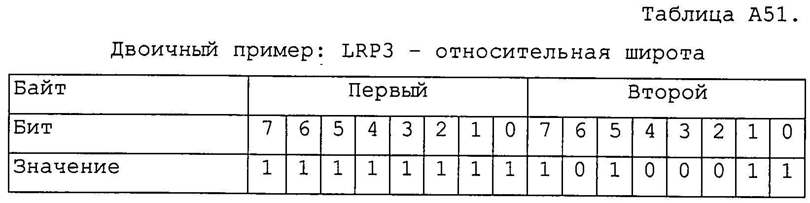

Двоичный пример: LRP3 - атрибут 4Table A53.
Binary example: LRP3 -
Двоичный пример: положительное смещениеTable A54.
Binary example:
Полный поток двоичных данных должен иметь длину в 24 байта и составлен следующим образом (в порядке байтов слева направо и сверху вниз):The full binary data stream should be 24 bytes long and composed as follows (in byte order from left to right and top to bottom):
Claims (12)
(i) сохраняют начальное положение в списке для поиска маршрута, причем упомянутое начальное положение является одним из:
- линией или сегментом, первым обнаруживаемым в упомянутом списке путей, или, если начальный узел упомянутой первой линии или сегмента является искусственным, первой линией или сегментом, обнаруживаемым в упомянутой цифровой карте, имеющим реальный начальный узел, который ведет непосредственно к упомянутой первой линии или сегменту, необязательно, через другие искусственные узлы,
- последней идентифицированной линией или сегментом отклонения, также обнаруживаемым в упомянутом списке путей,
(ii) определяют путь от начального узла начального положения и включают упомянутое начальное положение в конечный узел последней линии или сегмента в списке путей в рамках упомянутой цифровой карты, причем упомянутый путь определяют согласно алгоритму,
(iii) сравнивают кратчайший путь, определенный таким образом, со списком путей на идентичность, и при отсутствии идентичности, идентифицируют, по меньшей мере, одну линию или сегмент отклонения, являющиеся частью списка путей и имеющие начальный узел, представляющий пересечение в упомянутой цифровой карте, но не являющийся линией или сегментом, первым обнаруживаемым в упомянутом списке путей, и если такая линия или сегмент отклонения не завершается в конечном узле последней линии или сегмента, обнаруживаемого в списке путей, повторяют этап (i) с помощью упомянутой линии или сегмента отклонения, и
(iv) сохраняют последнюю линию или сегмент в списке путей в упомянутом списке для поиска маршрута, если еще не сохранены.1. A method for encoding a continuous path within a road network, said path being fully represented within a digital map and expressed as a list of paths of lines and / or segments existing in said digital map and sequentially ordered, wherein said method comprises the steps of:
(i) storing the starting position in the list for finding a route, said starting position being one of:
- a line or segment first found in said path list, or if the starting node of said first line or segment is artificial, a first line or segment found in said digital map having a real starting node that leads directly to said first line or segment optionally through other artificial nodes,
- the last identified line or segment deviation, also found in the list of paths,
(ii) determining the path from the starting node of the starting position and including said starting position in the end node of the last line or segment in the list of paths within said digital map, said path being determined according to an algorithm,
(iii) comparing the shortest path thus defined with a list of paths for identity, and in the absence of identity, identifying at least one line or segment of deviations that are part of the list of paths and having an initial node representing the intersection in said digital map, but not being the line or segment first found in the path list, and if such a line or deviation segment does not end at the end node of the last line or segment found in the path list, repeat the step (i) using said line or deviation segment, and
(iv) save the last line or segment in the list of paths in said list to search for a route, if not already saved.
Applications Claiming Priority (5)
| Application Number | Priority Date | Filing Date | Title |
|---|---|---|---|
| US12949108P | 2008-06-30 | 2008-06-30 | |
| US61/129,491 | 2008-06-30 | ||
| US19302708P | 2008-10-22 | 2008-10-22 | |
| US61/193,027 | 2008-10-22 | ||
| PCT/EP2009/058131 WO2010000707A1 (en) | 2008-06-30 | 2009-06-29 | An efficient location referencing method |
Publications (2)
| Publication Number | Publication Date |
|---|---|
| RU2011103154A RU2011103154A (en) | 2012-08-10 |
| RU2523171C2 true RU2523171C2 (en) | 2014-07-20 |
Family
ID=40976557
Family Applications (2)
| Application Number | Title | Priority Date | Filing Date |
|---|---|---|---|
| RU2011103154/08A RU2523171C2 (en) | 2008-06-30 | 2009-06-29 | Efficient location referencing method |
| RU2011103185/08A RU2490714C2 (en) | 2008-06-30 | 2009-06-29 | Method of determining location from encoded signals representing said location |
Family Applications After (1)
| Application Number | Title | Priority Date | Filing Date |
|---|---|---|---|
| RU2011103185/08A RU2490714C2 (en) | 2008-06-30 | 2009-06-29 | Method of determining location from encoded signals representing said location |
Country Status (11)
| Country | Link |
|---|---|
| US (2) | US8626438B2 (en) |
| EP (2) | EP2297719B1 (en) |
| JP (2) | JP5587306B2 (en) |
| KR (2) | KR101640461B1 (en) |
| CN (3) | CN102027521B (en) |
| AU (2) | AU2009265794A1 (en) |
| BR (2) | BRPI0912786B1 (en) |
| CA (2) | CA2725692C (en) |
| RU (2) | RU2523171C2 (en) |
| TW (2) | TWI465695B (en) |
| WO (2) | WO2010000706A1 (en) |
Families Citing this family (54)
| Publication number | Priority date | Publication date | Assignee | Title |
|---|---|---|---|---|
| US6587781B2 (en) | 2000-08-28 | 2003-07-01 | Estimotion, Inc. | Method and system for modeling and processing vehicular traffic data and information and applying thereof |
| US7620402B2 (en) | 2004-07-09 | 2009-11-17 | Itis Uk Limited | System and method for geographically locating a mobile device |
| JP5066206B2 (en) * | 2010-03-11 | 2012-11-07 | 日立オートモティブシステムズ株式会社 | Link string conversion method, road information providing apparatus, and road information providing system |
| JP5535711B2 (en) * | 2010-03-24 | 2014-07-02 | アルパイン株式会社 | Car navigation system and traffic information display method |
| US8954265B2 (en) | 2010-04-09 | 2015-02-10 | Tomtom North America, Inc. | Method of resolving a location from data representative thereof |
| US8496164B2 (en) * | 2010-05-19 | 2013-07-30 | Arinc Incorporated | Method and apparatus for customer/passenger specific interactive flight information data notification using boarding pass barcode scanning capabilities on low-cost display devices |
| US8723888B2 (en) | 2010-10-29 | 2014-05-13 | Core Wireless Licensing, S.a.r.l. | Method and apparatus for determining location offset information |
| JP5152306B2 (en) * | 2010-11-24 | 2013-02-27 | 株式会社デンソー | Road estimation device |
| JP5152305B2 (en) * | 2010-11-24 | 2013-02-27 | 株式会社デンソー | Road estimation device |
| EP2458332B1 (en) * | 2010-11-24 | 2016-03-30 | Denso Corporation | Road estimation device and method for estimating road |
| EP2458334A3 (en) * | 2010-11-24 | 2014-10-22 | Denso Corporation | Road estimation device and method for estimating road |
| DE102010063330A1 (en) * | 2010-12-17 | 2012-06-21 | Bayerische Motoren Werke Aktiengesellschaft | Method and device for compressing route data |
| EP2659226A1 (en) * | 2010-12-31 | 2013-11-06 | Tomtom Germany GmbH & Co. KG | Graph based topological map matching |
| GB201100403D0 (en) * | 2011-01-11 | 2011-02-23 | Totom Dev Germany Gmbh | An efficient location referencing method |
| EP2500887B1 (en) * | 2011-03-17 | 2020-09-09 | Harman Becker Automotive Systems GmbH | Description of a Road Segment Using ISO 17572-3 |
| GB2492369B (en) | 2011-06-29 | 2014-04-02 | Itis Holdings Plc | Method and system for collecting traffic data |
| BR112014000315A2 (en) | 2011-07-08 | 2016-08-23 | Syngenta Participations Ag | processes for the preparation of thietanamine |
| TWI454663B (en) * | 2011-11-22 | 2014-10-01 | Core Wireless Licensing Sarl | Method, apparatus and computer-readable storage medium for determining location offset information |
| TWI475192B (en) * | 2012-05-11 | 2015-03-01 | Wistron Corp | Navigation method, navigation system and map data downloading metnod for navigation |
| US9886794B2 (en) | 2012-06-05 | 2018-02-06 | Apple Inc. | Problem reporting in maps |
| US20130321400A1 (en) * | 2012-06-05 | 2013-12-05 | Apple Inc. | 3D Map Views for 3D Maps |
| US9052197B2 (en) | 2012-06-05 | 2015-06-09 | Apple Inc. | Providing navigation instructions while device is in locked mode |
| US9159153B2 (en) | 2012-06-05 | 2015-10-13 | Apple Inc. | Method, system and apparatus for providing visual feedback of a map view change |
| US9997069B2 (en) | 2012-06-05 | 2018-06-12 | Apple Inc. | Context-aware voice guidance |
| US9418672B2 (en) | 2012-06-05 | 2016-08-16 | Apple Inc. | Navigation application with adaptive instruction text |
| US10156455B2 (en) | 2012-06-05 | 2018-12-18 | Apple Inc. | Context-aware voice guidance |
| US10176633B2 (en) | 2012-06-05 | 2019-01-08 | Apple Inc. | Integrated mapping and navigation application |
| US9482296B2 (en) | 2012-06-05 | 2016-11-01 | Apple Inc. | Rendering road signs during navigation |
| US9863780B2 (en) | 2012-06-10 | 2018-01-09 | Apple Inc. | Encoded representation of traffic data |
| US11935190B2 (en) | 2012-06-10 | 2024-03-19 | Apple Inc. | Representing traffic along a route |
| GB201219742D0 (en) * | 2012-11-02 | 2012-12-12 | Tom Tom Int Bv | Methods and systems for generating a horizon for use in an advanced driver assistance system (adas) |
| CN103106258B (en) * | 2013-01-24 | 2016-02-10 | 北京世纪高通科技有限公司 | A kind of method of dynamic position decoding and device |
| US9063916B2 (en) * | 2013-02-27 | 2015-06-23 | Oracle International Corporation | Compact encoding of node locations |
| GB201321357D0 (en) | 2013-12-04 | 2014-01-15 | Tomtom Int Bv | A method of resolving a point location from encoded data representative thereof |
| US8942727B1 (en) | 2014-04-11 | 2015-01-27 | ACR Development, Inc. | User Location Tracking |
| US9413707B2 (en) | 2014-04-11 | 2016-08-09 | ACR Development, Inc. | Automated user task management |
| CN105677686B (en) * | 2014-11-21 | 2019-06-21 | 高德软件有限公司 | A kind of road codes method and device |
| US9933269B2 (en) | 2015-06-22 | 2018-04-03 | Here Global B.V. | Midpoint-based map-agnostic navigation routing |
| KR101776739B1 (en) | 2016-04-29 | 2017-09-08 | 현대자동차 주식회사 | Navigation and traffic information matching method thereof |
| US20190162547A1 (en) * | 2016-06-10 | 2019-05-30 | Hitachi Automotive Systems, Ltd. | Information Processing Device and Travel Control System |
| EP3476153B1 (en) * | 2016-06-22 | 2020-04-29 | Telefonaktiebolaget LM Ericsson (PUBL) | Candidate link locating by a wireless terminal |
| TWI585365B (en) * | 2016-10-13 | 2017-06-01 | 范振國 | Indoor navigation system and method based on relevancy of road signs |
| CN107818131A (en) * | 2017-09-20 | 2018-03-20 | 上海保橙网络科技有限公司 | A kind of method for comparing travel paths using string of binary characters |
| CN107832376B (en) * | 2017-10-30 | 2020-05-12 | 沈阳世纪高通科技有限公司 | Method and device for selecting position reference point |
| CN110345950B (en) * | 2018-04-08 | 2021-06-08 | 阿里巴巴(中国)有限公司 | Road coding method and road matching method |
| US11874123B2 (en) | 2019-02-01 | 2024-01-16 | Nec Corporation | Route planning apparatus, route planning method, and computer-readable recording medium |
| EP3742116A1 (en) * | 2019-05-22 | 2020-11-25 | Harman Becker Automotive Systems GmbH | Path data for navigation systems |
| CN110618684A (en) * | 2019-10-18 | 2019-12-27 | 辽宁瀚海工业机电设备有限公司 | AGV control method based on binary code and server thereof |
| US10969232B1 (en) * | 2019-12-06 | 2021-04-06 | Ushr Inc. | Alignment of standard-definition and High-Definition maps |
| DE112020006473B4 (en) | 2020-03-24 | 2024-02-01 | Mitsubishi Electric Corporation | Card matching device and card matching method |
| CN111860885B (en) * | 2020-07-07 | 2024-04-05 | 智能云科(沈阳)信息科技有限公司 | Method for identifying process route abnormality |
| DE102021205517A1 (en) | 2021-05-31 | 2022-12-01 | Robert Bosch Gesellschaft mit beschränkter Haftung | Method for determining an attribute on a digital map for a vehicle |
| KR102474014B1 (en) * | 2022-03-28 | 2022-12-06 | 주식회사 위밋모빌리티 | Method and apparatus for finding matching routes between different map databases |
| CN115292434B (en) * | 2022-09-29 | 2022-12-13 | 四川省交通勘察设计研究院有限公司 | GIS route visualization interaction method based on map engine |
Citations (4)
| Publication number | Priority date | Publication date | Assignee | Title |
|---|---|---|---|---|
| RU2153194C1 (en) * | 1999-06-21 | 2000-07-20 | Ашурков Виктор Васильевич | Method for detection of optimal route for vehicle which drives in city |
| RU2208765C1 (en) * | 2001-12-11 | 2003-07-20 | 16 Центральный научно-исследовательский испытательный институт | Navigational device |
| EP1335315A2 (en) * | 2002-02-12 | 2003-08-13 | The University of Tokyo | Dual Dijkstra search for planning multiple paths |
| GB2443472A (en) * | 2006-10-30 | 2008-05-07 | Cotares Ltd | Method of generating routes |
Family Cites Families (37)
| Publication number | Priority date | Publication date | Assignee | Title |
|---|---|---|---|---|
| US7003A (en) * | 1850-01-08 | Method oe counterbalancing sash by means of a heavy weight | ||
| US6092022A (en) * | 1997-02-28 | 2000-07-18 | Trimble Navigation | Optimal survey map projection system |
| WO1998054682A1 (en) * | 1997-05-30 | 1998-12-03 | Booth David S | Generation and delivery of travel-related, location-sensitive information |
| JPH11258981A (en) | 1998-03-11 | 1999-09-24 | Alpine Electronics Inc | Map data updating method of navigation device |
| US6192314B1 (en) * | 1998-03-25 | 2001-02-20 | Navigation Technologies Corp. | Method and system for route calculation in a navigation application |
| JP2001021377A (en) * | 1999-07-12 | 2001-01-26 | Clarion Co Ltd | Automobile navigation system and recording medium for navigation |
| AU768488B2 (en) | 1999-09-07 | 2003-12-11 | Robert Bosch Gmbh | Method for coding and decoding objects in a road traffic network |
| KR20070046106A (en) * | 1999-10-19 | 2007-05-02 | 아메리칸 캘카어 인코포레이티드 | Technique for effective navigation based on user preferences |
| US6405128B1 (en) * | 1999-12-20 | 2002-06-11 | Navigation Technologies Corp. | Method and system for providing an electronic horizon in an advanced driver assistance system architecture |
| US6415226B1 (en) * | 1999-12-20 | 2002-07-02 | Navigation Technologies Corp. | Method and system for providing safe routes using a navigation system |
| JP2001289646A (en) * | 2000-04-06 | 2001-10-19 | Ap One System Co Ltd | Position information display system |
| DE10061044C2 (en) * | 2000-12-08 | 2002-10-31 | Bosch Gmbh Robert | Procedure for the automatic deletion of a traffic report |
| JP4663136B2 (en) * | 2001-01-29 | 2011-03-30 | パナソニック株式会社 | Method and apparatus for transmitting location information of digital map |
| JP3656604B2 (en) | 2001-04-27 | 2005-06-08 | 住友電気工業株式会社 | Link travel time estimation apparatus and method |
| US6594576B2 (en) * | 2001-07-03 | 2003-07-15 | At Road, Inc. | Using location data to determine traffic information |
| KR100454922B1 (en) * | 2001-10-31 | 2004-11-15 | 삼성전자주식회사 | Navigation system for providing a real-time traffic information and method thereof |
| TWI245511B (en) * | 2002-01-10 | 2005-12-11 | Harris Corp | Wireless communication network including directional and omni-directional communication links and related methods |
| US7221287B2 (en) * | 2002-03-05 | 2007-05-22 | Triangle Software Llc | Three-dimensional traffic report |
| JP3909831B2 (en) * | 2002-03-28 | 2007-04-25 | 松下電器産業株式会社 | Shape vector generation apparatus, shape vector generation method, and shape vector generation program |
| WO2003093768A1 (en) * | 2002-04-30 | 2003-11-13 | Telmap Ltd. | Navigation system using corridor maps |
| WO2004021305A2 (en) * | 2002-08-29 | 2004-03-11 | Itis Holdings Plc | Apparatus and method for providing traffic information |
| US7079946B2 (en) * | 2003-08-29 | 2006-07-18 | Denso Corporation | Iterative logical renewal of navigable map database |
| KR100667518B1 (en) * | 2004-04-23 | 2007-01-10 | 엘지전자 주식회사 | Apparatus and method for processing traffic information |
| KR100667487B1 (en) * | 2004-04-23 | 2007-01-10 | 엘지전자 주식회사 | Method for mapping map data |
| US7349799B2 (en) * | 2004-04-23 | 2008-03-25 | Lg Electronics Inc. | Apparatus and method for processing traffic information |
| CN100334429C (en) * | 2004-05-08 | 2007-08-29 | 曲声波 | Data storage and update method for electronic map |
| JP2005345527A (en) * | 2004-05-31 | 2005-12-15 | Matsushita Electric Ind Co Ltd | Map information correcting system, map information correction method, program, map information provision system using the same, and information acquisition system |
| DE102004044968A1 (en) * | 2004-09-16 | 2006-04-06 | Siemens Ag | Navigation system and method for determining a route |
| US20060247852A1 (en) * | 2005-04-29 | 2006-11-02 | Kortge James M | System and method for providing safety-optimized navigation route planning |
| RU2272255C1 (en) * | 2005-05-11 | 2006-03-20 | Общество с ограниченной ответственностью "АЛЬТОНИКА" (ООО "АЛЬТОНИКА") | Dev for determining position of vehicle |
| JP4507991B2 (en) * | 2005-06-09 | 2010-07-21 | ソニー株式会社 | Information processing apparatus, information processing method, and program |
| JP2007104543A (en) * | 2005-10-07 | 2007-04-19 | Matsushita Electric Ind Co Ltd | Apparatus and method for compressing latitude/longitude data stream |
| CN1979597A (en) * | 2005-12-01 | 2007-06-13 | 李伟 | City road and public traffic station code and method and device for releasing inquiry |
| EP1921421A1 (en) * | 2006-11-10 | 2008-05-14 | Harman Becker Automotive Systems GmbH | Method and device for providing travel time information |
| JP2010541016A (en) * | 2007-10-02 | 2010-12-24 | テレ アトラス ベスローテン フエンノートシャップ | How to capture linear features along a reference line across a surface for use in a map database |
| JP5330508B2 (en) * | 2008-06-25 | 2013-10-30 | トムトム インターナショナル ベスローテン フエンノートシャップ | Navigation device, navigation device control method, program, and medium |
| US8285485B2 (en) * | 2010-03-18 | 2012-10-09 | Harman International Industries, Incorporated | Vehicle navigation system with route determination based on a measure of sportiness |
-
2009
- 2009-06-29 CN CN200980116958.4A patent/CN102027521B/en active Active
- 2009-06-29 JP JP2011515416A patent/JP5587306B2/en active Active
- 2009-06-29 RU RU2011103154/08A patent/RU2523171C2/en active
- 2009-06-29 AU AU2009265794A patent/AU2009265794A1/en not_active Abandoned
- 2009-06-29 CN CN201510509363.2A patent/CN105136158B/en active Active
- 2009-06-29 KR KR1020107029936A patent/KR101640461B1/en active IP Right Grant
- 2009-06-29 CA CA2725692A patent/CA2725692C/en active Active
- 2009-06-29 KR KR1020107029830A patent/KR101595020B1/en active IP Right Grant
- 2009-06-29 JP JP2011515417A patent/JP5667974B2/en active Active
- 2009-06-29 BR BRPI0912786-0A patent/BRPI0912786B1/en active IP Right Grant
- 2009-06-29 EP EP09772407.4A patent/EP2297719B1/en active Active
- 2009-06-29 US US12/736,713 patent/US8626438B2/en active Active
- 2009-06-29 US US12/736,714 patent/US8818707B2/en active Active
- 2009-06-29 AU AU2009265793A patent/AU2009265793A1/en not_active Abandoned
- 2009-06-29 EP EP09772406.6A patent/EP2304704B1/en active Active
- 2009-06-29 CA CA2725697A patent/CA2725697C/en active Active
- 2009-06-29 WO PCT/EP2009/058130 patent/WO2010000706A1/en active Application Filing
- 2009-06-29 WO PCT/EP2009/058131 patent/WO2010000707A1/en active Application Filing
- 2009-06-29 CN CN2009801168276A patent/CN102027520A/en active Pending
- 2009-06-29 RU RU2011103185/08A patent/RU2490714C2/en active
- 2009-06-29 BR BRPI0912270-2A patent/BRPI0912270B1/en active IP Right Grant
- 2009-06-30 TW TW098122183A patent/TWI465695B/en active
- 2009-06-30 TW TW098122181A patent/TWI465692B/en active
Patent Citations (4)
| Publication number | Priority date | Publication date | Assignee | Title |
|---|---|---|---|---|
| RU2153194C1 (en) * | 1999-06-21 | 2000-07-20 | Ашурков Виктор Васильевич | Method for detection of optimal route for vehicle which drives in city |
| RU2208765C1 (en) * | 2001-12-11 | 2003-07-20 | 16 Центральный научно-исследовательский испытательный институт | Navigational device |
| EP1335315A2 (en) * | 2002-02-12 | 2003-08-13 | The University of Tokyo | Dual Dijkstra search for planning multiple paths |
| GB2443472A (en) * | 2006-10-30 | 2008-05-07 | Cotares Ltd | Method of generating routes |
Also Published As
Similar Documents
| Publication | Publication Date | Title |
|---|---|---|
| RU2523171C2 (en) | Efficient location referencing method | |
| US10006774B2 (en) | Method of resolving a point location from encoded data representative thereof | |
| EP2663840B1 (en) | An efficient location referencing method | |
| EP2556337A1 (en) | A method of resolving a location from data representative thereof | |
| Ebendt et al. | An approach to geometry-based dynamic location referencing | |
| US20020183923A1 (en) | Method, data format, encoding device, decoding device and system | |
| TW201035523A (en) | A method of improving the quality of a location reference | |
| üdiger Ebendt et al. | An approach to geometry-based dynamic location referencing |
Legal Events
| Date | Code | Title | Description |
|---|---|---|---|
| PD4A | Correction of name of patent owner | ||
| PC43 | Official registration of the transfer of the exclusive right without contract for inventions |
Effective date: 20190416 |