RU2510139C2 - Resource allocation - Google Patents
Resource allocation Download PDFInfo
- Publication number
- RU2510139C2 RU2510139C2 RU2011119596/07A RU2011119596A RU2510139C2 RU 2510139 C2 RU2510139 C2 RU 2510139C2 RU 2011119596/07 A RU2011119596/07 A RU 2011119596/07A RU 2011119596 A RU2011119596 A RU 2011119596A RU 2510139 C2 RU2510139 C2 RU 2510139C2
- Authority
- RU
- Russia
- Prior art keywords
- fragments
- allocation
- subcarriers
- fragment
- data
- Prior art date
Links
Images
Classifications
-
- H—ELECTRICITY
- H04—ELECTRIC COMMUNICATION TECHNIQUE
- H04J—MULTIPLEX COMMUNICATION
- H04J14/00—Optical multiplex systems
- H04J14/02—Wavelength-division multiplex systems
- H04J14/0298—Wavelength-division multiplex systems with sub-carrier multiplexing [SCM]
-
- H—ELECTRICITY
- H04—ELECTRIC COMMUNICATION TECHNIQUE
- H04L—TRANSMISSION OF DIGITAL INFORMATION, e.g. TELEGRAPHIC COMMUNICATION
- H04L5/00—Arrangements affording multiple use of the transmission path
- H04L5/02—Channels characterised by the type of signal
-
- H—ELECTRICITY
- H04—ELECTRIC COMMUNICATION TECHNIQUE
- H04L—TRANSMISSION OF DIGITAL INFORMATION, e.g. TELEGRAPHIC COMMUNICATION
- H04L5/00—Arrangements affording multiple use of the transmission path
- H04L5/0091—Signaling for the administration of the divided path
- H04L5/0094—Indication of how sub-channels of the path are allocated
-
- H—ELECTRICITY
- H04—ELECTRIC COMMUNICATION TECHNIQUE
- H04J—MULTIPLEX COMMUNICATION
- H04J11/00—Orthogonal multiplex systems, e.g. using WALSH codes
-
- H—ELECTRICITY
- H04—ELECTRIC COMMUNICATION TECHNIQUE
- H04W—WIRELESS COMMUNICATION NETWORKS
- H04W72/00—Local resource management
- H04W72/04—Wireless resource allocation
-
- H—ELECTRICITY
- H04—ELECTRIC COMMUNICATION TECHNIQUE
- H04W—WIRELESS COMMUNICATION NETWORKS
- H04W72/00—Local resource management
- H04W72/04—Wireless resource allocation
- H04W72/044—Wireless resource allocation based on the type of the allocated resource
- H04W72/0446—Resources in time domain, e.g. slots or frames
-
- H—ELECTRICITY
- H04—ELECTRIC COMMUNICATION TECHNIQUE
- H04W—WIRELESS COMMUNICATION NETWORKS
- H04W72/00—Local resource management
- H04W72/04—Wireless resource allocation
- H04W72/044—Wireless resource allocation based on the type of the allocated resource
- H04W72/0453—Resources in frequency domain, e.g. a carrier in FDMA
-
- H—ELECTRICITY
- H04—ELECTRIC COMMUNICATION TECHNIQUE
- H04W—WIRELESS COMMUNICATION NETWORKS
- H04W72/00—Local resource management
- H04W72/20—Control channels or signalling for resource management
-
- H—ELECTRICITY
- H04—ELECTRIC COMMUNICATION TECHNIQUE
- H04W—WIRELESS COMMUNICATION NETWORKS
- H04W72/00—Local resource management
- H04W72/20—Control channels or signalling for resource management
- H04W72/23—Control channels or signalling for resource management in the downlink direction of a wireless link, i.e. towards a terminal
Abstract
Description
Область техники, к которой относится изобретениеFIELD OF THE INVENTION
Настоящее изобретение относится к сигнализированию выделения ресурсов в системе связи. Изобретение имеет конкретную, хотя неисключительную важность для сигнализирования поднесущих, используемых в системе связи с множественным доступом с ортогональным частотным разделением (OFDMA).The present invention relates to resource allocation signaling in a communication system. The invention is of particular, although non-exclusive, importance for signaling subcarriers used in an orthogonal frequency division multiple access (OFDMA) communication system.
Уровень техникиState of the art
OFDMA и FDMA с одной несущей выбраны в качестве схем множественного доступа в нисходящей линии связи и восходящей линии связи для радиоинтерфейса E-UTRA, в настоящее время изучаемого в 3GPP (который является основанным на стандартах сотрудничеством, изучающим будущее развитие систем мобильной связи третьего поколения). В рамках системы E-UTRA базовая станция, которая обменивается данными с рядом пользовательских устройств, выделяет общий объем частотно-временных ресурсов (в зависимости от полосы пропускания) среди максимально возможного количества одновременных пользователей, чтобы обеспечить эффективную и быструю адаптацию линии связи и добиться максимального выигрыша от многопользовательского разнесения. Ресурсы, выделяемые каждому пользовательскому устройству, основаны на мгновенных состояниях канала между пользовательским устройством и базовой станцией и сообщаются через канал управления, отслеживаемого посредством пользовательского устройства.The single-carrier OFDMA and FDMA are selected as the downlink and uplink multiple access schemes for the E-UTRA radio interface currently being studied in 3GPP (which is a standards-based collaboration exploring the future development of third generation mobile communication systems). Within the framework of the E-UTRA system, a base station that communicates with a number of user devices allocates the total amount of time-frequency resources (depending on the bandwidth) among the maximum possible number of simultaneous users in order to ensure efficient and quick adaptation of the communication line and achieve maximum gain from multi-user explode. The resources allocated to each user device are based on the instantaneous channel conditions between the user device and the base station and are communicated through a control channel monitored by the user device.
Сущность изобретенияSUMMARY OF THE INVENTION
Чтобы поддерживать большое число пользовательских устройств, требуется эффективный механизм сигнализирования ресурсов, использующий наименьшие возможные частотно-временные ресурсы.To support a large number of user devices, an efficient resource signaling mechanism is required that uses the smallest possible time-frequency resources.
Таким образом, в данной области техники очень желательно предоставить новый способ сигнализирования данных выделения ресурсов в системе связи, узле (или станции) связи, а следовательно, в пользовательских устройствах, и машиночитаемую программу для управления способом и устройством, устройствами и/или системой.Thus, in the art it is highly desirable to provide a new method of signaling resource allocation data in a communication system, a communication node (or station), and therefore in user devices, and a computer-readable program for controlling the method and device, devices and / or system.
Согласно первому аспекту настоящее изобретение предоставляет способ сигнализирования данных выделения ресурсов в системе связи, которая использует множество поднесущих, упорядоченных в последовательности фрагментов, при этом способ содержит: прием выделения поднесущих для каждого из пользовательских устройств; обработку принятых выделений, чтобы определить для каждого пользовательского устройства данные, идентифицирующие начальный фрагмент и конечный фрагмент в последовательности фрагментов, которая зависит от поднесущих, выделенных пользовательскому устройству; формирование соответствующих данных выделения ресурсов для каждого из пользовательских устройств с помощью упомянутых данных, идентифицирующих соответствующий начальный фрагмент и конечный фрагмент, определенный посредством этапа обработки; и сигнализирование соответствующих данных выделения ресурсов в каждое из множества пользовательских устройств.According to a first aspect, the present invention provides a method for signaling resource allocation data in a communication system that uses a plurality of subcarriers arranged in a sequence of fragments, the method comprising: receiving subcarrier allocation for each of the user devices; processing received allocations to determine, for each user device, data identifying the starting fragment and the ending fragment in a sequence of fragments that depends on the subcarriers allocated to the user device; generating corresponding resource allocation data for each of the user devices using said data identifying the corresponding starting fragment and the ending fragment determined by the processing step; and signaling corresponding resource allocation data to each of the plurality of user devices.
Каждое из пользовательских устройств затем может определять свои выделенные поднесущие посредством приема данных выделения ресурсов, идентифицирующих начальный фрагмент и конечный фрагмент в последовательности фрагментов, и посредством соотнесения этих данных с выделением поднесущих с помощью информации, хранимой или заданной в пользовательском устройстве.Each of the user devices can then determine its allocated subcarriers by receiving resource allocation data identifying the initial fragment and the final fragment in the sequence of fragments, and by correlating this data with the allocation of subcarriers using information stored or specified in the user device.
В одном режиме данные выделения ресурсов включают в себя битовую комбинацию, которая задает группирование последовательности фрагментов в последовательность групп в зависимости от поднесущих, выделенных пользовательским устройствам, наряду с идентификатором ресурсов, который идентифицирует группу фрагментов, выделенных этому пользовательскому устройству. В этом случае идентификатор ресурсов предпочтительно зависит от позиции группы в последовательности групп.In one mode, the resource allocation data includes a bit pattern that defines the grouping of a sequence of fragments into a sequence of groups depending on the subcarriers allocated to user devices, along with a resource identifier that identifies a group of fragments allocated to this user device. In this case, the resource identifier preferably depends on the position of the group in the sequence of groups.
В альтернативном режиме данные выделения ресурсов содержат уникальное значение, относящееся к комбинации начального фрагмента и конечного фрагмента выделенной группы фрагментов. Для некоторых выделений группа фрагментов может содержать один фрагмент, и при этом начальный фрагмент и конечный фрагмент являются идентичными. Данные, идентифицирующие начальный и конечный фрагмент, могут идентифицировать фрагменты непосредственно или косвенно. Например, данные, идентифицирующие эти фрагменты, могут идентифицировать начальный фрагмент или конечный фрагмент и число фрагментов между начальным фрагментом и конечным фрагментом.In an alternative mode, the resource allocation data contains a unique value related to the combination of the initial fragment and the final fragment of the selected group of fragments. For some selections, a group of fragments may contain one fragment, and the initial fragment and the final fragment are identical. Data identifying the start and end fragment can identify the fragments directly or indirectly. For example, data identifying these fragments can identify the starting fragment or the ending fragment and the number of fragments between the starting fragment and the ending fragment.
В предпочтительном режиме может быть выполнен ряд различных типов выделений поднесущих. В этом случае обработка, выполняемая в кодере, и обработка, выполняемая в декодере, будет зависеть от типа выделения, которое используется, и данные, идентифицирующие тип выделения, также должны быть сигнализированы пользовательским устройствам, с тем чтобы они могли выполнять надлежащую обработку принятых данных выделения ресурсов.In a preferred mode, a number of different types of subcarrier allocations can be performed. In this case, the processing performed in the encoder and the processing performed in the decoder will depend on the type of allocation that is used, and data identifying the type of allocation should also be signaled to user devices so that they can properly process the received allocation data resources.
Для выделения ресурсов требуются эффективные методики кодирования для кодирования данных выделения ресурсов, которые должны быть сигнализированы ряду пользовательских устройств в системе связи. В одной методике кодирования битовая комбинация выделения ресурсов передается всем пользователям вместе с идентификатором ресурсов для каждого пользователя. Каждый пользователь затем идентифицирует свои выделенные поднесущие с помощью принятой битовой комбинации выделения и принятого идентификатора ресурсов. В другой методике кодирования используется кодовое дерево, чтобы формировать значение, представляющее выделение поднесущих. Затем пользовательское устройство использует кодовое дерево для того, чтобы определить выделение поднесущих из сигнализированного значения.Resource allocation requires efficient coding techniques for encoding resource allocation data, which should be signaled to a number of user devices in the communication system. In one coding technique, a resource allocation bit combination is transmitted to all users along with a resource identifier for each user. Each user then identifies their allocated subcarriers using the received bit combination of the allocation and the received resource identifier. Another coding technique uses a code tree to generate a value representing subcarrier allocation. The user device then uses the code tree to determine the allocation of subcarriers from the signaled value.
Этап формирования может включать в себя: формирование битовой комбинации, которая задает группирование последовательности фрагментов в последовательность групп в зависимости от поднесущих, выделенных каждому пользовательскому устройству; формирование идентификатора ресурсов для каждой группы в зависимости от положения группы в последовательности групп; при этом данные выделения для пользовательского устройства содержат битовую комбинацию и соответствующий идентификатор ресурсов.The forming step may include: forming a bit combination, which defines the grouping of a sequence of fragments into a sequence of groups depending on the subcarriers allocated to each user device; the formation of a resource identifier for each group depending on the position of the group in the sequence of groups; wherein the allocation data for the user device comprises a bit pattern and a corresponding resource identifier.
Этап сигнализирования может сообщать битовую комбинацию по каналу сигнализирования, общему для пользовательских устройств.The signaling step may report a bit pattern on a signaling channel common to user devices.
Этап сигнализирования может сообщать идентификатор ресурсов для пользовательского устройства по каналу сигнализирования, выделенному этому пользовательскому устройству.The signaling step may report a resource identifier for the user device on the signaling channel allocated to that user device.
Битовая комбинация может включать в себя бит, ассоциативно связанный с каждым из второго и последующих фрагментов в последовательности фрагментов, значение которого задает, является или нет ассоциативно связанный фрагмент началом новой группы в последовательности групп.The bit combination may include a bit associated with each of the second and subsequent fragments in the sequence of fragments, the value of which determines whether or not the associatively connected fragment is the beginning of a new group in the sequence of groups.
Битовая комбинация может содержать N-1 битов, где N - это число фрагментов в последовательности фрагментов.The bit combination may contain N-1 bits, where N is the number of fragments in the sequence of fragments.
Идентификатор ресурсов для группы позволяет идентифицировать группу посредством ее позиции в последовательности групп.The resource identifier for the group allows you to identify the group by its position in the sequence of groups.
Этап формирования может содержать использование предварительно определенного отображения, которое соотносит данные, идентифицирующие начальный и конечный фрагменты для пользовательского устройства, с уникальным значением, и данные выделения ресурсов для пользовательского устройства могут содержать значение.The generation step may comprise using a predetermined mapping that correlates data identifying the start and end fragments for the user device with a unique value, and resource allocation data for the user device may comprise a value.
Отображение может быть задано посредством одного или более уравнений.A mapping may be defined by one or more equations.
Отображение может быть задано посредством следующего выражения:The mapping may be specified by the following expression:
еслиif

x = N(P-1)+Ox = N (P-1) + O
иначеotherwise
x = N(N-(P-1))+(N-1-O)x = N (N- (P-1)) + (N-1-O)
где ![]()
![]()
Отображение может быть задано посредством структуры данных, которая задает кодовое дерево, содержащее множество листьев и имеющее глубину, соответствующую числу фрагментов в последовательности фрагментов.The mapping may be defined by a data structure that defines a code tree containing a plurality of leaves and having a depth corresponding to the number of fragments in the sequence of fragments.
Отображение может быть задано посредством таблицы поиска.The mapping may be specified by means of a lookup table.
Этап сигнализирования может сообщать данные выделения ресурсов для пользовательского устройства по каналу сигнализирования, выделенному этому пользовательскому устройству.The signaling step may report resource allocation data for the user device via the signaling channel allocated to that user device.
Принимаемые данные могут идентифицировать тип выделения поднесущих, при этом обработка, выполняемая на этапе обработки, зависит от идентифицированного типа выделения, а этап формирования может формировать данные выделения ресурсов, которые включают в себя данные типа, идентифицирующие тип выделения.The received data can identify the type of subcarrier allocation, wherein the processing performed in the processing step depends on the identified allocation type, and the generation step can generate resource allocation data, which includes type data identifying the allocation type.
Одним типом выделения может быть локализованное выделение фрагментов, при котором пользовательскому устройству выделяется множество последовательных фрагментов поднесущих.One type of allocation may be localized fragment allocation, in which a plurality of consecutive subcarrier fragments are allocated to a user device.
Одним типом выделения может быть распределенное выделение фрагментов, при котором пользовательскому устройству выделяется множество последовательных фрагментов, рассредоточенных в рамках поддерживаемой полосы пропускания.One type of allocation may be distributed fragment allocation, wherein a user device is allocated a plurality of consecutive fragments dispersed within a supported bandwidth.
Одним типом выделения может быть распределенное выделение несущих, при котором пользовательскому устройству выделяется множество возможно прерывных поднесущих, рассредоточенных в рамках поддерживаемой полосы пропускания.One type of allocation may be distributed carrier allocation, in which a plurality of possibly discontinuous subcarriers are allocated to a user device dispersed within a supported bandwidth.
Этап формирования может быть выполнен с возможностью кодировать идентификатор определенного начального фрагмента и определенного конечного фрагмента при формировании данных выделения ресурсов.The forming step may be configured to encode the identifier of a specific start fragment and a specific end fragment when generating resource allocation data.
Система связи может использовать множество подполос, каждая из которых содержит поднесущие, упорядоченные в последовательности фрагментов, и способ может формировать соответствующие данные выделения ресурсов для выделения поднесущих в каждой подполосе.A communication system may use multiple subbands, each of which contains subcarriers arranged in a sequence of fragments, and the method may generate respective resource allocation data for allocating subcarriers in each subband.
Данные выделения ресурсов для подполосы могут быть сигнализированы в рамках этой подполосы.The resource allocation data for a subband may be signaled within that subband.
Согласно второму аспекту настоящее изобретение предоставляет способ определения выделения несущих частот в системе связи, которая использует множество поднесущих, упорядоченных в последовательности фрагментов, при этом способ содержит: прием данных выделения ресурсов, идентифицирующих начальный фрагмент и конечный фрагмент в последовательности фрагментов; сохранение информации, которая соотносит данные выделения ресурсов с последовательностью фрагментов поднесущих; и определение выделенных поднесущих с помощью принимаемых данных выделения ресурсов и сохраненной информации.According to a second aspect, the present invention provides a method for determining carrier allocation in a communication system that uses a plurality of subcarriers arranged in a sequence of fragments, the method comprising: receiving resource allocation data identifying a starting fragment and an ending fragment in a sequence of fragments; storing information that correlates resource allocation data with a sequence of subcarrier fragments; and determining the allocated subcarriers using the received resource allocation data and stored information.
Этап приема может принимать данные выделения ресурсов, содержащие: битовую комбинацию и идентификатор ресурсов, упомянутый в первом аспекте. Т.е. данные выделения ресурсов содержат: битовую комбинацию, которая задает группирование последовательности фрагментов в последовательность групп в зависимости от поднесущих, выделенных каждому пользовательскому устройству; и идентификатор ресурсов для одной из групп, причем идентификатор ресурсов зависит от позиции этой группы в последовательности групп.The receiving step may receive resource allocation data comprising: a bit pattern and a resource identifier mentioned in the first aspect. Those. the resource allocation data contains: a bit combination that defines the grouping of a sequence of fragments into a sequence of groups depending on the subcarriers allocated to each user device; and a resource identifier for one of the groups, the resource identifier depending on the position of this group in the sequence of groups.
Этап приема может принимать битовую комбинацию по общему каналу сигнализирования, общему для системы связи.The receiving step may receive a bit combination over a common signaling channel common to a communication system.
Этап приема может принимать идентификатор ресурсов по выделенному каналу сигнализирования в системе связи.The receiving step may receive a resource identifier on a dedicated signaling channel in a communication system.
Битовая комбинация может включать в себя бит, ассоциативно связанный с каждым из второго и последующих фрагментов в последовательности фрагментов, значение которого задает, является или нет ассоциативно связанный фрагмент началом новой группы в последовательности групп.The bit combination may include a bit associated with each of the second and subsequent fragments in the sequence of fragments, the value of which determines whether or not the associatively connected fragment is the beginning of a new group in the sequence of groups.
Битовая комбинация может содержать N-1 битов, где N - это число фрагментов в последовательности фрагментов.The bit combination may contain N-1 bits, where N is the number of fragments in the sequence of fragments.
Принимаемый идентификатор ресурсов позволяет идентифицировать одну из групп посредством ее позиции в последовательности групп.The received resource identifier allows one of the groups to be identified by its position in the sequence of groups.
Этап определения может использовать идентификатор ресурсов для того, чтобы идентифицировать позиции ассоциативно связанных битов в битовой комбинации и определять начальные и конечные фрагменты из определенных битовых позиций.The determination step may use a resource identifier in order to identify the positions of the associated bits in the bit combination and determine the start and end fragments from the specific bit positions.
Этап приема может содержать прием данных выделения ресурсов, которые содержат значение, которое связано с данными, идентифицирующими начальные и конечные фрагменты посредством предварительно определенного отображения, при этом хранимая информация задает отображение и при этом этап определения определяет выделение поднесущих с помощью принимаемых данных выделения ресурсов и отображения.The receiving step may comprise receiving resource allocation data that contains a value that is associated with data identifying the start and end fragments by means of a predetermined display, wherein the stored information sets the display and the determination step determines the allocation of subcarriers using the received resource allocation and display data .
Отображение может быть задано посредством одного или более уравнений.A mapping may be defined by one or more equations.
Этап определения может определять значение O, соответствующее начальному фрагменту, и значение P, идентифицирующее число последовательных фрагментов между начальным фрагментом и конечным фрагментом, из следующего выражения:The determination step may determine the O value corresponding to the initial fragment, and the P value identifying the number of consecutive fragments between the initial fragment and the final fragment from the following expression:

b=x modN b = x mod N
Если (a+b>N) If (a + b> N)
P=N+2-aP = N + 2-a
O=N-1-bO = N-1-b
иначеotherwise
P=aP = a
O=bO = b
где ![]()
![]()
Отображение может быть задано посредством структуры данных, которая задает кодовое дерево, содержащее множество листьев и имеющее глубину, соответствующую числу фрагментов в последовательности фрагментов.The mapping may be defined by a data structure that defines a code tree containing a plurality of leaves and having a depth corresponding to the number of fragments in the sequence of fragments.
Отображение может быть задано посредством таблицы поиска.The mapping may be specified by means of a lookup table.
Этап приема может принимать данные выделения ресурсов по выделенному каналу сигнализирования в системе связи.The receiving step may receive resource allocation data on a dedicated signaling channel in a communication system.
Принимаемые данные выделения ресурсов могут содержать данные, которые идентифицируют тип выделения поднесущих, и определение, выполненное на этапе определения, может зависеть от идентифицированного типа выделения.The received resource allocation data may include data that identifies the subcarrier allocation type, and the determination made in the determination step may depend on the identified allocation type.
Одним типом выделения может быть локализованное выделение фрагментов, при котором пользовательскому устройству выделяется множество последовательных фрагментов поднесущих, и этап определения может определять выделение поднесущих как множество непрерывных поднесущих фрагмента или фрагментов в рамках и между идентифицированными начальным и конечным фрагментами.One type of allocation may be localized fragment allocation, in which a plurality of consecutive subcarrier fragments are allocated to a user device, and the determination step may determine subcarrier allocation as a plurality of continuous subcarriers of a fragment or fragments within and between the identified start and end fragments.
Одним типом выделения может быть распределенное выделение фрагментов, при котором пользовательскому устройству выделяется множество распределенных фрагментов поднесущих, и этап определения может содержать этапы определения числа фрагментов между идентифицированными начальным и конечным фрагментами и определение разнесения между фрагментами посредством деления общего числа фрагментов в последовательности на число фрагментов между идентифицированными начальным и конечным фрагментами.One type of allocation may be distributed fragment allocation, in which a plurality of distributed subcarrier fragments are allocated to a user device, and the determination step may include the steps of determining the number of fragments between the identified initial and final fragments and determining spacing between the fragments by dividing the total number of fragments in the sequence by the number of fragments between identified start and end fragments.
Этап определения может определять начальный фрагмент в зависимости от выделений фрагментов для других пользовательских устройств.The determination step may determine the initial fragment depending on the fragment allocations for other user devices.
Одним типом выделения может быть распределенное выделение поднесущих, при котором пользовательскому устройству выделяется множество распределенных поднесущих, и этап определения может содержать этапы определения числа фрагментов между идентифицированными начальным и конечным фрагментами и определения разнесения между поднесущими посредством деления общего числа фрагментов в последовательности на число фрагментов между идентифицированными начальным и конечным фрагментами.One type of allocation may be distributed subcarrier allocation, in which a plurality of distributed subcarriers is allocated to a user device, and the determination step may include the steps of determining the number of fragments between the identified start and end fragments and determining the spacing between subcarriers by dividing the total number of fragments in the sequence by the number of fragments between the identified initial and final fragments.
Этап определения может определять начальную поднесущую в зависимости от выделений поднесущих для других пользовательских устройств.The determination step may determine an initial subcarrier depending on subcarrier allocations for other user devices.
Система связи может использовать множество подполос, каждая из которых может содержать поднесущие, упорядоченные в последовательности фрагментов, и при этом способ может формировать соответствующие данные выделения ресурсов для выделения поднесущих во множестве подполос.A communication system may use multiple subbands, each of which may contain subcarriers ordered in a sequence of fragments, and the method may generate corresponding resource allocation data for allocating subcarriers in multiple subbands.
Данные выделения ресурсов для подполосы могут приниматься в рамках этой подполосы.The resource allocation data for the subband may be received within this subband.
Данные выделения могут быть кодированы, и этап определения может содержать этап декодирования данных выделения, с тем чтобы определить начальный и конечный фрагменты или идентифицировать данные, задающие начальный и конечный фрагменты.The selection data may be encoded, and the determination step may comprise the step of decoding the selection data in order to determine the start and end fragments or to identify data specifying the start and end fragments.
Согласно третьему аспекту предусмотрен узел (станция) связи, который выполнен с возможностью осуществлять связь с множеством пользовательских устройств с помощью множества поднесущих, упорядоченных в последовательности фрагментов, и который выполнен с возможностью сигнализировать выделения поднесущих каждому из пользовательских устройств с помощью способа согласно любому из первого аспекта.According to a third aspect, there is provided a communication node (station) that is configured to communicate with a plurality of user devices using a plurality of subcarriers arranged in a sequence of fragments, and which is configured to signal subcarrier allocations to each of the user devices using a method according to any one of the first aspect .
Согласно четвертому аспекту предусмотрено пользовательское устройство, которое выполнено с возможностью осуществлять связь с узлом (станцией) связи по третьему аспекту и которое выполнено с возможностью определять выделение поднесущих с помощью способа по любому из второго аспекта.According to a fourth aspect, a user device is provided which is configured to communicate with a communication node (station) according to the third aspect and which is configured to determine subcarrier allocation using the method of any of the second aspect.
Согласно пятому аспекту предусмотрены машинореализуемые инструкции, чтобы вызвать выполнение программируемым вычислительным устройством способа сигнализирования по любому из первого аспекта.According to a fifth aspect, machine-executable instructions are provided to cause the programmable computing device to execute a signaling method according to any one of the first aspect.
Согласно шестому аспекту предусмотрены машинореализуемые инструкции, чтобы вызвать осуществление программируемым вычислительным устройством способа определения выделения поднесущих по любому из второго аспекта.According to a sixth aspect, machine-executable instructions are provided to cause a programmable computing device to implement a method for determining subcarrier allocation according to any one of the second aspect.
Машинореализуемые инструкции по пятому и шестому аспекту могут быть записаны на машиночитаемом носителе.Machine-implemented instructions for the fifth and sixth aspect can be recorded on a machine-readable medium.
Согласно седьмому аспекту, в частности, предусмотрен узел (или станция) связи, который выполнен с возможностью осуществлять связь с множеством пользовательских устройств, используя множество поднесущих, упорядоченных в последовательности фрагментов, при этом узел связи содержит: приемник, выполненный с возможностью принимать выделение поднесущих для каждого из пользовательских устройств; процессор, выполненный с возможностью обрабатывать принятые выделения, чтобы определить для каждого пользовательского устройства данные, идентифицирующие начальный фрагмент и конечный фрагмент в последовательности фрагментов, которая зависит от поднесущих, выделенных пользовательскому устройству; формирователь, выполненный с возможностью формировать соответствующие данные выделения ресурсов для каждого из пользовательских устройств с помощью данных, идентифицирующих соответствующие начальный фрагмент и конечный фрагмент, определенные посредством процессора; и вывод, выполненный с возможностью выводить данные выделения соответствующих ресурсов в каждое из множества пользовательских устройств.According to a seventh aspect, in particular, there is provided a communication node (or station) that is configured to communicate with a plurality of user devices using a plurality of subcarriers arranged in a sequence of fragments, wherein the communication node comprises: a receiver configured to receive subcarrier allocation for each of the user devices; a processor configured to process the received allocations to determine for each user device data identifying the initial fragment and the final fragment in a sequence of fragments that depends on the subcarriers allocated to the user device; a shaper configured to generate corresponding resource allocation data for each of the user devices using data identifying the corresponding start fragment and end fragment determined by the processor; and an output configured to output allocation data of respective resources to each of a plurality of user devices.
Согласно восьмому аспекту, в частности, предусмотрено пользовательское устройство, которое выполнено с возможностью осуществлять связь с узлом связи, который выполнен с возможностью осуществлять связь с множеством пользовательских устройств с помощью множества поднесущих, размещенных в последовательности фрагментов, при этом пользовательское устройство содержит: приемник, выполненный с возможностью принимать данные выделения ресурсов, идентифицирующие начальный фрагмент и конечный фрагмент в рамках последовательности фрагментов; память или схему, выполненную с возможностью сохранять информацию, соотносящую данные выделения ресурсов с последовательностью фрагментов; и определитель, выполненный с возможностью определять выделенные поднесущие с помощью принятых данных выделения ресурсов и хранимой информации.According to an eighth aspect, in particular, there is provided a user device that is configured to communicate with a communication node that is configured to communicate with a plurality of user devices using a plurality of subcarriers arranged in a sequence of fragments, wherein the user device comprises: a receiver with the ability to receive resource allocation data identifying the initial fragment and the final fragment within the sequence of fragments ; a memory or circuit configured to store information relating resource allocation data to a sequence of fragments; and a determiner configured to determine the allocated subcarriers using the received resource allocation data and stored information.
Согласно дополнительному аспекту предусмотрен способ или устройство сигнализирования выделений поднесущих фактически так, как описано в данном документе со ссылкой или как показано на прилагаемых чертежах; и способ или устройство для приема и декодирования выделения поднесущих фактически так, как описано в данном документе со ссылкой или как показано на прилагаемых чертежах.According to a further aspect, there is provided a method or apparatus for signaling subcarrier allocations in fact as described herein with reference or as shown in the accompanying drawings; and a method or apparatus for receiving and decoding subcarrier allocation in fact as described herein with reference or as shown in the accompanying drawings.
Эти и другие аспекты изобретения должны стать очевидными из последующего подробного описания режимов, которые предоставляются только в качестве примера и которые описываются со ссылкой на прилагаемые чертежи.These and other aspects of the invention should become apparent from the following detailed description of the modes, which are provided by way of example only and which are described with reference to the accompanying drawings.
Краткое описание чертежейBrief Description of the Drawings
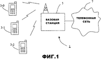
Фиг.1 схематично иллюстрирует систему связи, содержащую ряд пользовательских мобильных (сотовых) телефонов, которые осуществляют связь с базовой станцией, подключенной к телефонной сети;Figure 1 schematically illustrates a communication system comprising a number of user mobile (cellular) telephones that communicate with a base station connected to a telephone network;
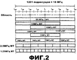
Фиг.2 иллюстрирует способ, которым полоса пропускания канала связи базовой станции, показанной на фиг.1, может быть выделена ряду различных мобильных телефонов, имеющих различную поддерживаемую полосу пропускания;Figure 2 illustrates the manner in which the bandwidth of the communication channel of the base station shown in figure 1, can be allocated to a number of different mobile phones having different supported bandwidth;
Фиг.3 - это блок-схема, иллюстрирующая основные компоненты базовой станции, показанной на фиг.1;Figure 3 is a block diagram illustrating the main components of the base station shown in figure 1;
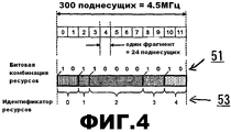
Фиг.4 иллюстрирует способ, которым фрагменты поднесущих в рамках подполосы 5 МГц могут быть сгруппированы во множество групп для выделения различным мобильным телефонам;Figure 4 illustrates the way in which fragments of subcarriers within the 5 MHz subband can be grouped into many groups for allocation to various mobile phones;
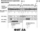
Фиг.5A иллюстрирует способ, которым поднесущие могут выделяться на основе локализованного выделения, при котором каждому мобильному телефону выделяется множество последовательных фрагментов поднесущих;Fig. 5A illustrates a method by which subcarriers can be allocated based on localized allocation in which multiple consecutive subcarrier fragments are allocated to each mobile phone;
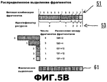
Фиг.5B иллюстрирует способ, которым та же методика кодирования может быть использована для того, чтобы выделять поднесущие с помощью распределенного выделения фрагментов, при котором каждому мобильному телефону выделяется множество фрагментов, рассредоточенных по поддерживаемой полосе пропускания;Fig. 5B illustrates a method by which the same coding technique can be used to allocate subcarriers using distributed fragment allocation, in which each mobile phone is allocated a plurality of fragments dispersed over a supported bandwidth;
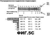
Фиг.5C иллюстрирует способ, которым та же методика кодирования может быть использована для того, чтобы выделять поднесущие с помощью распределенных поднесущих, при котором каждому мобильному телефону выделяется множество возможно прерывных поднесущих, рассредоточенных по поддерживаемой полосе пропускания;Fig. 5C illustrates a method by which the same coding technique can be used to allocate subcarriers using distributed subcarriers, in which many possibly discontinuous subcarriers are allocated to each mobile phone dispersed over a supported bandwidth;
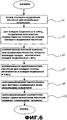
Фиг.6 - это блок-схема последовательности операций способа, иллюстрирующая обработку, выполняемую модулем кодера, формирующим часть базовой станции, показанной на фиг.3;6 is a flowchart illustrating processing performed by an encoder module forming part of the base station shown in FIG. 3;
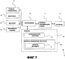
Фиг.7 - это блок-схема, иллюстрирующая основные компоненты одного из мобильных телефонов, показанных на фиг.1;7 is a block diagram illustrating the main components of one of the mobile phones shown in figure 1;
Фиг.8 - это блок-схема последовательности операций способа, иллюстрирующая основные этапы обработки, выполняемой модулем декодера, формирующим часть мобильного телефона, показанного на фиг.7;FIG. 8 is a flowchart illustrating the main steps of processing performed by a decoder module forming part of the mobile phone shown in FIG. 7;
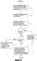
Фиг.9 иллюстрирует способ, которым фрагменты поднесущих в рамках подполосы 2,5 МГц могут быть сгруппированы во множество групп для выделения различным мобильным телефонам; иFIG. 9 illustrates a method by which subcarrier fragments within a 2.5 MHz subband can be grouped into multiple groups for allocation to various mobile phones; FIG. and
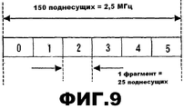
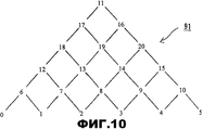
Фиг.10 схематично иллюстрирует кодовое дерево, используемое модулем кодера базовой станции в альтернативном режиме для того, чтобы кодировать начальный и конечный фрагмент, задающий выделение поднесущих для пользователя.10 schematically illustrates a code tree used by an encoder module of a base station in an alternative mode in order to encode a start and end fragment specifying subcarrier allocation for a user.
Режимы осуществления изобретенияModes for Carrying Out the Invention
ОбзорOverview
Фиг.1 схематично иллюстрирует систему 1 мобильной (сотовой) связи, в которой пользователи мобильных телефонов 3-0, 3-1 и 3-2 могут осуществлять связь с другими пользователями (не показаны) посредством базовой станции 5 и телефонной сети 7. В этом режиме базовая станция 5 использует методику множественного доступа с ортогональным частотным разделением (OFDMA), при которой данные, которые должны быть переданы в мобильные телефоны 3, модулируются на множестве поднесущих. Различные поднесущие выделяются каждому мобильному телефону 3 в зависимости от поддерживаемой полосы пропускания мобильного телефона 3 и объема данных, который должен быть отправлен в мобильный телефон 3. В этом режиме базовая станция 5 также выделяет поднесущие, используемые для того, чтобы переносить данные в соответствующие мобильные телефоны 3, чтобы постараться поддержать равномерное распределение мобильных телефонов 3, работающих в рамках полосы пропускания базовой станции. Чтобы достичь этих целей, базовая станция 5 динамически выделяет поднесущие для каждого мобильного телефона 3 и сигнализирует выделения для каждой временной точки (субкадра) в каждый из координируемых мобильных телефонов 3.1 schematically illustrates a mobile (cellular)
Фиг.2 иллюстрирует пример способа, которым базовая станция 5 может выделять поднесущие в рамках поддерживаемой полосы пропускания различным мобильным телефонам 3, имеющим различные поддерживаемые полосы пропускания. В этом режиме базовая станция 5 имеет поддерживаемую полосу пропускания в 20 МГц, из которых 18 МГц используются для передачи данных. На фиг.2 MT представляет мобильный терминал.2 illustrates an example of a method by which a
Для того чтобы каждый из мобильных телефонов 3 мог быть информирован о решении по координации в рамках каждой подполосы, каждый мобильный телефон 3 требует совместно используемого канала управления в рамках закрепленной полосы частот. Информация, сигнализируемая по этому каналу управления, включает в себя:In order for each of the
i) информацию выделения блоков ресурсов (для осуществления связи по нисходящей линии связи и осуществления связи по восходящей линии связи);i) resource block allocation information (for downlink communication and uplink communication);
ii) информацию демодуляции блоков ресурсов для нисходящей линии связи;ii) downlink resource block demodulation information;
iii) информацию демодуляции блоков ресурсов для восходящей линии связи;iii) uplink resource block demodulation information;
iv) ACK/NACK для передачи по восходящей линии связи; иiv) ACK / NACK for uplink transmission; and
v) синхронизирующие управляющие биты.v) synchronizing control bits.
Поскольку число битов, доступных в канале управления, ограничено, требуются эффективные способы для того, чтобы транспортировать требуемую информацию с помощью наименьшего числа битов. Изобретение относится к способу, которым информация выделения ресурсов может быть сигнализирована эффективным способом каждому из мобильных телефонов 3.Since the number of bits available on the control channel is limited, efficient methods are required to transport the required information using the smallest number of bits. The invention relates to a method in which resource allocation information can be signaled in an effective manner to each of the
Базовая станцияBase station
Фиг.3 - это блок-схема, иллюстрирующая основные компоненты базовой станции 5, используемой в этом режиме. Как показано, базовая станция 5 включает в себя приемопередающую схему 21, которая выполнена с возможностью передавать сигналы и принимать сигналы от мобильных телефонов 3 посредством одной или более антенн 23 (с помощью вышеописанных поднесущих) и которая выполнена с возможностью передавать сигналы и принимать сигналы из телефонной сети 7 через сетевой интерфейс 25. Работа приемопередающей схемы 21 управляется контроллером 27 в соответствии с программным обеспечением, сохраненным в памяти 29. Программное обеспечение включает в себя, помимо прочего, операционную систему 31 и модуль 33 выделения ресурсов. Модуль 33 выделения ресурсов выполнен с возможностью выделения поднесущих, используемых посредством приемопередающей схемы 21 при осуществлении связи с мобильными телефонами 3. Как показано на фиг.3, модуль 33 выделения ресурсов также включает в себя модуль 35 кодера, который кодирует выделение в эффективное представление, которое затем передается в соответствующие мобильные телефоны 3.Figure 3 is a block diagram illustrating the main components of a
В этом режиме базовая станция 5 может использовать три различных типа выделения поднесущих:In this mode,
i) выделение локализованных фрагментов, при котором каждому мобильному телефону 3 выделяется множество последовательных фрагментов поднесущих, причем в данном режиме каждый фрагмент - это множество из 25 последовательных поднесущих;i) the allocation of localized fragments, in which each
ii) выделение распределенных фрагментов, при котором каждому мобильному телефону 3 выделяется множество фрагментов, рассредоточенных по полосе пропускания, поддерживаемой посредством мобильного телефона 3; иii) allocation of distributed fragments, in which each
iii) выделение распределенных поднесущих, при котором каждому мобильному телефону 3 выделяется множество возможно прерывных поднесущих, рассредоточенных по полосе пропускания, поддерживаемой посредством мобильного телефона 3.iii) allocation of distributed subcarriers, in which each
Первая методика кодированияFirst coding technique
Первая методика кодирования, которую модуль 35 кодера может использовать для того, чтобы кодировать вышеописанную информацию выделения ресурсов, далее описывается со ссылкой на фиг.4-6. Фиг.4 схематично иллюстрирует способ, при котором 300 поднесущих в пределах подполосы 5 МГц рабочей полосы пропускания базовой станции делятся на последовательность из двенадцати фрагментов (обозначенных 0, 1, 2, 3, ..., 11), каждый из которых содержит 25 поднесущих. Информация, задающая это упорядочение фрагментов, может быть сохранена как данные в памяти базовой станции 5 (и в мобильных телефонах 3) либо она может быть задана в программных либо аппаратных схемах, запущенных на ней. Фиг.4 также иллюстрирует способ, которым модуль 35 кодера разделяет в этом режиме фрагменты поднесущих на последовательность групп (в данном случае пять групп) в зависимости от текущего выделения поднесущих. В примере, проиллюстрированном на фиг.4, первая группа содержит фрагменты 0 и 1; вторая группа содержит фрагмент 3; третья группа содержит фрагменты 3-7; четвертая группа содержит фрагменты 8 и 9; и пятая группа содержит фрагменты 10 и 11.The first encoding technique that encoder
Фиг.4 также иллюстрирует битовую комбинацию 51 выделения ресурсов, которая формируется посредством модуля 35 кодера и которая задает группирование фрагментов. Как показано, битовая комбинация 51 выделения ресурсов включает в себя один бит для каждого из двенадцати фрагментов в рамках этой подполосы, которому присваивается значение 1, когда соответствующий фрагмент является первым фрагментом в новой группе, и в противном случае присваивается значение 0. Специалисты в данной области техники должны признавать, что первый бит из 12-битовой комбинации 51 битов является избыточным и не должен быть сигнализирован (передан), поскольку первый фрагмент в рамках подполосы всегда является первым фрагментом в первой группе.FIG. 4 also illustrates a resource
Фиг.4 также иллюстрирует идентификатор 53 ресурсов, который предоставляется для каждой из заданных групп. Как показано, в этом режиме идентификатор ресурсов для группы идентифицирует группу посредством ее позиции в последовательности групп. В частности, идентификаторы ресурсов неявно нумеруются слева направо согласно ассоциативно связанной позиции группы в последовательности групп.4 also illustrates a
Каждый мобильный телефон 3 затем информируется о выделении в рамках каждой подполосы в 5 МГц посредством сигнализирования соответствующей битовой комбинации 51 выделения ресурсов и одного из идентификаторов 53 ресурсов. В этом режиме битовые комбинации 51 выделения ресурсов сигнализируются мобильным телефонам 3 по общему каналу сигнализирования в каждой подполосе 5 МГц, а идентификатор(ы) 53 ресурсов для каждого мобильного телефона 3 отдельно сигнализируются по выделенному каналу управления. В этом режиме каждый идентификатор 53 ресурсов сигнализируется как 3-битовое число, приводя к максимальному числу в восемь мобильных телефонов 3, которые могут координироваться в подполосе 5 МГц. Мобильные телефоны 3 с большей полосой пропускания могут комбинировать несколько подполос 5 МГц и декодировать свое общее выделение ресурсов из битовой комбинации 51 выделения ресурсов и идентификатора 53 ресурсов из каждой подполосы.Each
Специалисты в данной области техники должны признавать, что способ, которым модуль 35 кодера формирует вышеописанные битовые комбинации 51 выделения ресурсов и идентификаторы 53 ресурсов, варьируется в зависимости от того, как выделены поднесущие (т.е. с помощью локализованного выделения фрагментов, распределенного выделения фрагментов или распределенного выделения поднесущих). Примеры этих различных типов выделений далее описываются со ссылкой на фиг.5.Those skilled in the art will recognize that the way the
Локализованное выделение фрагментовLocalized fragment selection
Фиг.5A иллюстрирует один пример, когда поднесущие выделены трем мобильным телефонам 3, показанным на фиг.1, с помощью выделения локализованных фрагментов. В частности, в этом примере мобильный телефон 3-0 имеет поддерживаемую полосу пропускания в 10 МГц и ему выделяются фрагменты 10 и 11 в первой подполосе и фрагменты 0 и 1 во второй подполосе. Аналогично, в этом примере мобильный телефон 3-1 имеет поддерживаемую полосу пропускания в 10 МГц и ему выделяется фрагмент 2 в первой подполосе и фрагменты 3, 4, и 5 во второй подполосе. Отметим, что первая подполоса означает первые 300 поднесущих (обозначенных 51-1) на фиг.5A, а вторая подполоса означает вторые 300 поднесущих (обозначенных 51-2) на фиг.5A. Наконец, в этом примере мобильный телефон 3-2 имеет поддерживаемую полосу пропускания в 5 МГц и ему выделяются фрагменты 3, 4, 5, 6 и 7 в первой подполосе. Фиг.5A показывает две различные битовые комбинации 51-1 и 51-2 ресурсов и соответствующие идентификаторы ресурсов, сформированные посредством модуля 35 кодера для двух проиллюстрированных подполос. Фиг.5A также иллюстрирует внизу чертежа идентификатор ресурсов, который сигнализируется соответствующим мобильным телефонам 3. Поскольку каждый мобильный телефон 3 принимает только 1 идентификатор ресурсов для каждой подполосы в 5 МГц, которую он занимает, его выделение поднесущих является непрерывным в рамках каждой подполосы. Тем не менее мобильному телефону 3, имеющему поддерживаемую полосу пропускания в 10 МГц, могут выделяться ресурсы в каждой из подполос в 5 МГц, которые он занимает, и эти ресурсы не обязательно должны быть непрерывны друг относительно друга, как проиллюстрировано на фиг.5A для мобильного телефона 3-1.FIG. 5A illustrates one example where subcarriers are allocated to the three
Как описано выше, в этом режиме предполагается, что самое большее восемь мобильных телефонов 3 могут координироваться в рамках каждой подполосы в 5 МГц в каждую временную точку (субкадр). Следовательно, может показаться, что имеется некоторая избыточность в 12-битовой битовой комбинации 51 выделения ресурсов (которая может предоставить возможность до 12 идентификаторов ресурсов в каждой подполосе). Тем не менее, даже в случае если максимальное число в восемь мобильных телефонов 3 координировано в подполосе, по-прежнему возможно, что некоторые поднесущие не используются. Например, если восьми мобильным телефонам 3 выделен один фрагмент поднесущих, а оставшиеся 4 неиспользуемых фрагмента не находятся в непрерывном блоке, то до двенадцати битов (или одиннадцати, если игнорируется первый бит, как описано выше) по-прежнему требуется для того, чтобы задавать разделение фрагментов, чтобы достичь требуемого выделения.As described above, in this mode, it is assumed that at most eight
Распределенное выделение фрагментовDistributed Fragmentation
Фиг.5B иллюстрирует способ, которым тот же тип битовой комбинации 51 выделения ресурсов и идентификатора 53 ресурсов может быть использован, когда используется схема выделения распределенных фрагментов. Фиг.5B иллюстрирует фактическое выделение 61 фрагментов для 5 различных мобильных телефонов 3, идентифицированных посредством различных затенений. В проиллюстрированном примере одному мобильному телефону 3 выделяется 6 фрагментов (а именно, фрагменты 0, 2, 4, 6, 8 и 10); одному мобильному телефону выделяется 3 фрагмента (а именно, фрагменты 1, 5 и 9); а остальным 3 мобильным телефонам 3 каждому выделяется 1 фрагмент поднесущих. В этом режиме для того, чтобы упростить декодирование данных выделения ресурсов в мобильных телефонах 3, разделение фрагментов упорядочивается в порядке уменьшения относительно числа фрагментов на группу. Для примера, показанного на фиг.5B, это означает, что группа, содержащая 6 фрагментов, размещается первой, за ней следует группа, содержащая 3 фрагмента, за которой следуют 3 оставшиеся группы, каждая из которых содержит 1 фрагмент. Поскольку идентификаторы ресурсов для этих групп фрагментов пронумерованы слева направо, это означает то, что мобильному телефону 3 с наибольшим числом выделенных фрагментов предоставляется наименьший идентификатор, пользователю со вторым наибольшим числом выделенных фрагментов предоставляется следующий наименьший идентификатор и т.д. Специалистам в данной области техники должно быть очевидным, что число фрагментов, выделяемых каждому мобильному телефону 3, должно учитывать число фрагментов, выделяемых остальным мобильным телефонам 3 с меньшим идентификатором ресурсов, чтобы избежать коллизии ресурсов в ходе декодирования сигнализирования ресурсов.5B illustrates a method by which the same type of resource
Распределенное выделение поднесущихDistributed Subcarrier Allocation
Фиг.5C схематично иллюстрирует пример распределенного выделения поднесущих, которое может быть использовано. Как в случае с примером, проиллюстрированным на фиг.5B, в примере, показанном на фиг.5C, имеется пять мобильных телефонов, причем первому мобильному телефону 3 выделены поднесущие 0, 2, 4, ..., 298; второму мобильному телефону 3 выделены поднесущие 1, 5, 9, ..., 297; третьему мобильному телефону 3 выделены поднесущие 3, 15, ..., 291; четвертому мобильному телефону 3 выделены поднесущие 7, 19, ..., 295; и пятому мобильному телефону 3 выделены поднесущие 11, 23, ..., 299.5C schematically illustrates an example of a distributed subcarrier allocation that may be used. As in the case of the example illustrated in FIG. 5B, in the example shown in FIG. 5C, there are five mobile phones, the
В этом проиллюстрированном примере разнесение между поднесущими, выделенными первому мобильному телефону 3, составляет 2, разнесение между поднесущими, выделенными второму мобильному телефону 3, составляет 4 и разнесение между поднесущими, выделенными трем оставшимся мобильным телефонам, составляет 12. В этом иллюстративном примере все мобильные телефоны 3 занимают 6 доступных фрагментов, но с различным разнесением поднесущих. Выделение идентично распределенному выделению фрагментов, повторяемому так, чтобы охватывать всю полосу пропускания в 5 МГц, при этом полоса пропускания фрагмента заменена полосой пропускания 25 поднесущих. Фиг.5C иллюстрирует результирующую битовую комбинацию 51 выделения ресурсов и идентификаторы 53 ресурсов для этого выделения поднесущих.In this illustrated example, the spacing between the subcarriers allocated to the first
Биты типа выделенияHighlight bits
Специалисты в данной области техники должны признавать то, что для того, чтобы мобильные телефоны 3 могли определять корректное выделение поднесущих, они должны информироваться о типе выделения поднесущих, которое выполнено (т.е. локализованное выделение фрагментов, распределенное выделение фрагментов или распределенное выделение поднесущих). Эта информация сигнализируется всем мобильным телефонам 3 с помощью следующей 2-битовой комбинации типа выделения ресурсов:Those of skill in the art should recognize that in order for
Как подробнее описывается ниже, мобильные телефоны 3 используют эту битовую комбинацию типа выделения для того, чтобы идентифицировать то, как они должны интерпретировать группу фрагментов, которая выделена им, с помощью битовой комбинации 51 выделения ресурсов и идентификатора 53 ресурсов.As described in more detail below,
Сущность работы модуля кодераThe essence of the operation of the encoder module
Фиг.6 - это блок-схема последовательности операций способа, иллюстрирующая основные этапы обработки, выполняемой модулем 35 кодера, чтобы определить вышеописанные битовые комбинации 51 выделения ресурсов и идентификаторы 53 ресурсов для различных мобильных телефонов 3, координируемых для текущей временной точки. Как показано, на этапе s1 модуль 35 кодера принимает текущее выделение поднесущих, которое включает в себя сведения в отношении того, выполнено ли выделение в соответствии со схемой локализованного выделения фрагментов, схемой распределенного выделения фрагментов или схемой распределенного выделения поднесущих. На этапе s3 модуль 35 кодера разделяет фрагменты поднесущих в каждой из четырех подполос в 5 МГц базовой станции на группы на основе принятого выделения поднесущих. Специалисты в данной области техники должны признавать, что обработка, выполненная этапе s3, должна зависеть от типа выделения поднесущих, которое было выполнено. На этапе s5 модуль 35 кодера формирует описанную битовую комбинацию 51 выделения ресурсов для каждой подполосы в 5 МГц, которая представляет раздел фрагментов в этой подполосе. Затем на этапе s7 модуль 35 кодера формирует идентификатор ресурсов для каждой группы фрагментов в каждой подполосе для сигнализирования соответствующему мобильному телефону 3.6 is a flowchart illustrating the main steps of processing performed by the
После того как идентификаторы 53 ресурсов сформированы для групп фрагментов в каждой подполосе в 5 МГц, обработка переходит к этапу s9, на котором модуль 35 кодера сигнализирует (передает) битовые комбинации 51 выделения ресурсов всем мобильным телефонам 3. В частности, на этом этапе модуль 35 кодера сигнализирование приемопередающей схемой 21 по общему каналу сигнализирования в каждой подполосе в 5 МГц, битовую комбинацию 51 выделения ресурсов, представляющую разделение фрагментов в рамках этой подполосы. Следовательно, мобильные телефоны 3 должны иметь возможность принимать битовые комбинации 51 выделения ресурсов для всех подполос, в которых они работают. Например, если мобильные телефоны 3-0 и 3-1 имеют рабочую полосу пропускания в 10 МГц, а мобильный телефон 3-2 имеет рабочую полосу пропускания в 5 МГц, то мобильные телефоны 3-0 и 3-1 должны принимать две битовые комбинации 51 выделения ресурсов по своим общим каналам сигнализирования, а мобильный телефон 3-2 должен принять одну битовую комбинацию 51 в пределах своего общего канала сигнализирования. Вышеописанная 2-битовая комбинация типа выделения ресурсов также передается с каждой битовой комбинацией 51 выделения ресурсов на этапе s9. После этапа s9 обработка переходит к этапу s11, на котором модуль 35 кодера сигнализирует соответствующие идентификаторы 53 ресурсов каждому мобильному телефону 3 в выделенном канале сигнализирования мобильного телефона в каждой подполосе по 5 МГц.After the
Следовательно, в первой методике кодирования для каждой подполосы в 5 МГц сигнализируются всего 14 битов общего канала (13, если первый бит комбинации выделения ресурсов не сигнализируется), и сигнализируются три бита идентификаторов ресурсов для каждого пользовательского устройства.Therefore, in the first coding technique, for each 5 MHz subband, only 14 bits of the common channel are signaled (13 if the first bit of the resource allocation combination is not signaled), and three bits of resource identifiers for each user device are signaled.
Мобильный телефонMobile phone
Фиг.7 схематично иллюстрирует основные компоненты каждого из мобильных телефонов 3, показанных на фиг.1. Как показано, мобильные телефоны 3 включают в себя приемопередающую схему 71, которая выполнена с возможностью передавать сигналы и принимать сигналы от базовой станции 5 через одну или более антенн 73. Как показано, мобильный телефон 3 также включает в себя контроллер 75, который управляет работой мобильного телефона 3 и который подключен к приемопередающей схеме 71, а также к громкоговорителю 77, микрофону 79, дисплею 81 и клавишной панели 83. Контроллер 75 работает в соответствии с программными инструкциями, сохраненными в памяти 85. Как показано, эти программные инструкции включают в себя, помимо прочего, операционную систему 87 и модуль 89 связи. В этом режиме модуль 89 связи включает в себя модуль 91 декодера, который выполнен с возможностью декодировать данные выделения ресурсов, сигнализируемые базовой станцией 5, чтобы определять выделение поднесущих мобильного телефона для текущей временной точки.FIG. 7 schematically illustrates the main components of each of the
Способ, которым модуль 91 декодера декодирует данные выделения ресурсов, принятые от базовой станции 5, далее описывается со ссылкой на блок-схему последовательности операций способа, показанную на фиг.8. Как показано, на этапе s21 модуль 91 декодера принимает битовую комбинацию 51 выделения ресурсов и ассоциативно связанную 2-битовую комбинацию типа выделения из каждого принятого общего канала сигнализирования. Как должно стать очевидным из вышеприведенного описания, число битовых комбинаций 51 выделения ресурсов и число комбинаций типа выделения зависит от поддерживаемой полосы пропускания мобильного телефона 3. На этапе s23 модуль 91 декодера принимает идентификатор(ы) 53 ресурсов из выделенного канала(ов) сигнализирования. Число принимаемых идентификаторов 53 ресурсов также зависит от поддерживаемой полосы пропускания мобильного телефона 3. Далее на этапе s25 модуль 91 декодера идентифицирует для каждой поддерживаемой полосы в 5 МГц начальный и конечный фрагменты группы фрагментов, ассоциативно связанных с идентификатором 53 ресурсов, принимаемым для этой подполосы. Модуль 91 декодера идентифицирует эти начальный и конечный фрагменты с помощью соответствующей битовой комбинации 51 выделения ресурсов, принимаемой для этой подполосы. Например, если принятый идентификатор 53 ресурсов является двоичным значением 010, соответствующим идентификатору ресурсов в 2, то модуль 91 декодера обрабатывает соответствующую битовую комбинацию 51 выделения ресурсов, чтобы идентифицировать битовые позиции первой и третьей единиц при подсчете слева (и игнорировании первого бита в битовой комбинации 51 выделения ресурсов, если она включает в себя 12 битов, поскольку первый бит всегда соответствует началу первой группы). Битовая позиция этой второй единицы идентифицирует начало группы, имеющей идентификатор ресурсов в 2, а битовая позиция третьей единицы идентифицирует фрагмент, который находится в начале следующей группы в последовательности групп, из которого модуль 91 декодера может определить конечный фрагмент группы, имеющей идентификатор ресурсов в 2. В примере, проиллюстрированном на фиг.5A для первой подполосы, вторая единица в битовой комбинации 51 выделения ресурсов (с игнорированием первого бита) является четвертым битом с левого конца, а третья единица в битовой комбинации 51 является девятым битом с левого конца. Как можно видеть из фиг.5A, это означает то, что группа фрагментов, соответствующих идентификатору ресурсов в 2, содержит фрагменты 3-7 в этой подполосе в 5 МГц.The method by which the
После того как начальный и конечный фрагменты группы, ассоциативно связанной с принятым идентификатором 53 ресурсов, определены, обработка переходит к s27, на котором модуль 91 декодера использует принятую 2-битовую комбинацию типа выделения, чтобы определить, является ли выделение выделением локализованных фрагментов. Если да, то обработка переходит к этапу s29, на котором модуль 91 декодера определяет то, что выделенные поднесущие соответствуют непрерывному множеству поднесущих в рамках и между идентифицированными начальным и конечным фрагментами. Для вышеприведенного примера это должно привести к выделению модулем 91 декодера поднесущих во фрагментах 3-7 (включая) для осуществления связи с базовой станцией 5.After the start and end fragments of the group associated with the received
Если на этапе s27 модуль 91 декодера определяет то, что 2-битовая комбинация типа выделения не соответствует выделению локализованных фрагментов, то обработка переходит к этапу s31, на котором модуль 91 декодера определяет, соответствует ли 2-битовая комбинация типа выделения выделению распределенных фрагментов. Если соответствует, то обработка переходит к этапу s33, на котором модуль 91 декодера использует идентифицированные начальный и конечный фрагменты для того, чтобы определить разнесение между фрагментами посредством деления общего числа фрагментов в подполосе на число фрагментов между идентифицированным начальным и конечным фрагментами. Например, для распределенного выделения фрагментов, показанного на фиг.5B, и когда принятый идентификатор 53 ресурсов равен 1, общее число фрагментов в подполосе равно 12, а число фрагментов между идентифицированными начальным и конечным фрагментами равно 3. Следовательно, 3 фрагмента выделяются в рамках данной подполосы, которые разнесены на 4 (12/3=4) фрагмента. Положение первого из этих фрагментов в подполосе зависит от выделения поднесущих для других координируемых мобильных телефонов 3 в рамках этой подполосы. Как следствие, когда распределенное выделение ресурсов выбрано, модуль 91 декодера также рассматривает выделение фрагментов для других мобильных телефонов 3, координируемых в это время. Модуль 91 декодера делает это посредством идентификации позиций всех "единиц" в битовой комбинации 51 выделения ресурсов, чтобы определить общее число фрагментов, выделяемых в других группах. Для выделения, показанного на фиг.5B, модуль декодера идентифицирует то, что группа, соответствующая идентификатору ресурсов в 0, имеет 6 фрагментов; что группа, соответствующая идентификатору ресурсов в 1, имеет 3 фрагмента и что оставшиеся 3 группы, соответствующие идентификаторам ресурсов в 2, 3 и 4, каждая имеют по 1 фрагменту. Из этой информации модуль 91 декодера определяет то, что фрагменты, ассоциативно связанные с идентификатором ресурсов в 0, должны быть разнесены на 2 фрагмента.If in step s27, the
В этом режиме схема распределенного выделения ресурсов упорядочена так, что первый фрагмент в подполосе всегда выделяется первому фрагменту, выделенному идентификатору ресурсов "0". Следовательно, для вышеприведенного примера выделенными фрагментами для идентификатора ресурсов "0" являются фрагменты 0, 2, 4, 6, 8 и 10. Модуль 91 декодера затем рассматривает выделенные фрагменты для ресурса "1". Как описано выше, разнесение между фрагментами для идентификатора ресурсов "1" равно 4. Модуль 91 декодера далее выделяет первый фрагмент для идентификатора ресурсов "1" как являющийся первым доступным фрагментом, после того как фрагменты для идентификатора ресурсов "0" выделены. В этом примере первым невыделенным фрагментом является фрагмент 1 и, следовательно, фрагментами, выделенными идентификатору ресурсов "1", являются фрагменты 1, 5 и 9. Аналогичным образом первым фрагментом, который доступен для выделения для идентификатора ресурсов "2", является фрагмент 3 и т.д.In this mode, the distributed resource allocation scheme is ordered so that the first fragment in the subband is always allocated to the first fragment allocated to resource identifier "0". Therefore, for the above example, the selected fragments for the resource identifier “0” are
Специалисты в данной области техники должны признавать, что поскольку группы фрагментов упорядочены таким образом, что наибольшие группы имеют наименьшие идентификаторы 53 ресурсов, чем их собственный, в данном режиме мобильный телефон 3 должен учитывать только выделения фрагментов для групп с меньшим идентификатором 53 ресурсов при определении положения первого выделенного фрагмента в подполосе.Those of skill in the art should recognize that since the groups of fragments are arranged in such a way that the largest groups have the
Если на этапе s31 модуль 91 декодера определяет то, что 2-битовая комбинация типа выделения не соответствует выделению распределенных фрагментов, то модуль 91 декодера определяет, что выделение соответствует выделению распределенных поднесущих, как показано на фиг.5C. В этом случае обработка переходит к этапу s35, на котором модуль 91 декодера определяет число поднесущих, выделенных мобильному телефону 3, посредством умножения числа фрагментов в выделенной группе на число поднесущих в каждом фрагменте (т.е. на двадцать пять). Модуль 91 декодера также вычисляет разнесение между поднесущими посредством деления общего числа фрагментов в подполосе на число фрагментов в выделенной группе. Позиция первой поднесущей далее определяется как первая поднесущая, доступная после того как поднесущие выделены для групп, ассоциативно связанных с идентификаторами ресурсов, имеющими меньшие значения, аналогичным способом, при котором начальный фрагмент был определен в обработке распределенного выделения фрагментов, описанной выше.If in step s31, the
После того как модуль 91 декодера определил выделение поднесущих (на этапе s29, этапе s33 или этапе s35), модуль 91 декодера отправляет соответствующие управляющие сигналы в приемопередающую схему 71, чтобы управлять приемом данных с помощью идентифицированных поднесущих. Затем обработка завершается.After the
Вторая методика кодированияSecond coding technique
Вторая методика кодирования, которую модуль 35 кодера в базовой станции 5 может использовать для того, чтобы кодировать вышеописанную информацию выделения ресурсов, далее описывается со ссылкой на фиг.4, 9 и 10. Как проиллюстрировано на фиг.4, рабочая полоса пропускания в 20 МГц базовой станции 5 может быть поделена на подполосы различных размеров, причем наименьшая подполоса соответствует полосе пропускания в 1,25 МГц. Число фрагментов, доступных для каждой подполосы, приведено в таблице ниже.A second encoding technique that the
В этой второй методике кодирования треугольное кодовое дерево используется с числом фрагментов, доступных для конкретной полосы пропускания, равным числу листьев в основании кодового дерева. Для приема подполосы в 2,5 МГц, показанной на фиг.9, которая имеет 6 фрагментов, соответствующее кодовое дерево проиллюстрировано на фиг.10. Как показано, кодовое дерево 91 сформировано из дерева вершин, имеющего глубину в N вершин, соответствующую числу фрагментов в подполосе, и имеющего N листьев в нижней строке кодового дерева 91. В данном примере предусмотрено шесть фрагментов и, следовательно, дерево имеет глубину 6. Общее число вершин в дереве равно N(N+1)/2. Число вершин из этого дерева, следовательно, может быть сигнализировано с помощью ceil(log2(N*(N+1)/2)) числа битов. Точное число битов, требуемых для каждой полосы пропускания, приведено в таблице ниже:In this second coding technique, the triangular code tree is used with the number of fragments available for a particular bandwidth equal to the number of leaves at the base of the code tree. To receive the 2.5 MHz subband shown in FIG. 9, which has 6 fragments, the corresponding code tree is illustrated in FIG. 10. As shown, the
В этом режиме нумерация вершин задается таким образом, чтобы оптимизировать число сигнализирующих битов, требуемых для того, чтобы сигнализировать конкретное выделение ресурсов. В примере, проиллюстрированном на фиг.9 и 10, для полосы пропускания в 2,5 МГц сигнализируется 5-битовое число, чтобы уникально определить начальный фрагмент и число последовательных выделенных фрагментов (которое идентифицирует конечный фрагмент). В общем случае, когда имеется N фрагментов в подполосе, начальный фрагмент (O) и число последующих фрагментов (P), которые выделены, может быть сигнализировано как целое число x без знака следующим образом:In this mode, the vertex numbering is set in such a way as to optimize the number of signaling bits required in order to signal a specific resource allocation. In the example illustrated in FIGS. 9 and 10, a 5-bit number is signaled for a bandwidth of 2.5 MHz to uniquely determine the starting fragment and the number of consecutive extracted fragments (which identifies the final fragment). In general, when there are N fragments in a subband, the initial fragment (O) and the number of subsequent fragments (P) that are highlighted can be signaled as an unsigned integer x as follows:
если
x=N(P-1)+Ox = N (P-1) + O
иначеotherwise
x=N(N-(P-1))+(N-1-O)x = N (N- (P-1)) + (N-1-O)
где ![]()
![]()

b=xmodN b = x mod N
Если (a+b>N) If (a + b> N)
O=N-1-bO = N-1-b
иначеotherwise
P=aP = a
O=bO = b
где ![]()
![]()
Одно преимущество данной методики кодирования заключается в том, что таблицы поиска (или структуры кодового дерева) не требуются для того, чтобы выполнять кодирование или декодирование. Дополнительно, деление на N, выполняемое приемником, также может быть реализовано посредством простой операции умножения и сдвига.One advantage of this encoding technique is that lookup tables (or code tree structures) are not required in order to perform encoding or decoding. Additionally, the division by N performed by the receiver can also be realized by a simple operation of multiplication and shift.
Для локализованного распределения фрагментов каждому мобильному телефону 3 сигнализируется номер вершины, который преобразуется в множество листьев. В качестве примера, если одному мобильному телефону 3 выделены фрагменты 0 и 1, другому мобильному телефону 3 выделены фрагменты 2, 3 и 4, а третьему мобильному телефону 3 выделен фрагмент 5 из полосы пропускания в 2,5 МГц, проиллюстрированной на фиг.9, то первому мобильному телефону 3 сигнализируется значение 6, второму мобильному телефону 3 сигнализируется значение 14, а третьему мобильному телефону 3 сигнализируется значение 5. Эти значения предпочтительно определяются с помощью первого уравнения, приведенного выше. Альтернативно эти номера вершин могут быть определены из древовидной структуры 91 посредством идентификации корневой вершины, которая является общей для выделенных фрагментов. Например, для первого мобильного телефона 3, где выделенные фрагменты соответствуют фрагментам 0 и 1, корневая вершина, которая является общей для этих вершин, - вершина с номером 6. Аналогично для второго мобильного телефона 3, которому выделены фрагменты 2, 3 и 4, вершина, которая является общим корнем для начального фрагмента 2 и конечного фрагмента 4, - это вершина с номером 14. В завершение, для третьего мобильного телефона, которому выделен фрагмент 5, поскольку имеется только 1 фрагмент, нет общей вершины, а, следовательно, номер вершины, который сигнализируется, соответствует номеру выделенного фрагмента (т.е. 5).For localized distribution of fragments, each vertex number is signaled to each
В случае распределенного выделения фрагментов для той же полосы пропускания те же уравнения могут быть использованы, чтобы сигнализировать фрагменты, которые выделены. Например, если мобильному телефону 3 выделены фрагменты 1 и 5, то число 16 сигнализируется вместе с индикатором распределенного выделения фрагментов. В мобильном телефоне значения P и O декодируются так, как описано выше, тем не менее их интерпретация другая. В частности, при распределенном выделении фрагментов значение P означает разнесение между фрагментами, а значение O означает первый фрагмент в распределенном выделении.In the case of distributed fragment allocation for the same bandwidth, the same equations can be used to signal fragments that are highlighted. For example, if
Мультиплексирование распределенного выделения фрагментов и локализованного выделения фрагментов в одну временную точку также легко поддерживается с помощью этого способа кодирования. Например, одному мобильному телефону 3 может быть выделено локализованное выделение и сигнализировано значение 14, которое отображается во фрагменты 2, 3, и 4, тогда как другому мобильному телефону выделено распределенное выделение фрагментов и сигнализировано значение 16, которое отображается во фрагменты 1 и 5.Multiplexing of distributed fragment allocation and localized fragment isolation at one time point is also easily supported using this encoding method. For example, a localized allocation can be allocated to one
Распределенное выделение поднесущих с другим разнесением для других мобильных телефонов также может поддерживаться с помощью вышеприведенной схемы кодирования. В этом случае значения O и P также интерпретируются по-другому. В этом случае, поскольку распределенное выделение поднесущих выбрано, значение O должно идентифицировать смещение выделенных поднесущих, а значение P должно задавать разнесение между поднесущими. Например, если мобильному телефону 3 сигнализировано значение 16 и индикатор того, что распределенное выделение поднесущих выполнено, то сдвиг поднесущих равен 1, а разнесение между поднесущими равно 5. Аналогично то, что мобильному телефону 3 сигнализировано значение 14 и индикатор распределенных поднесущих, предполагает сдвиг поднесущих в 2 и разнесение между поднесущими в 3. Специалисты в данной области техники должны признавать, что мультиплексирование локализованного фрагмента и распределенной поднесущей невозможно при этой методике кодирования.Distributed subcarrier allocation with different diversity for other mobile phones can also be supported using the above coding scheme. In this case, the values of O and P are also interpreted differently. In this case, since the distributed subcarrier allocation is selected, the value O should identify the offset of the allocated subcarriers, and the value P should specify the spacing between the subcarriers. For example, if the value of 16 is signaled to the
Хотя вышеозначенные примеры иллюстрируют ситуацию для подполосы в 2,5 МГц, это сделано только для простоты иллюстрирования. Выделение ресурсов в рамках общей полосы пропускания базовой станции может выполняться в единицах характеристик приема в нисходящей линии связи различных мобильных телефонов 3. Например, если все мобильные телефоны 3 могут принимать, по меньшей мере, 5 МГц, то выделение ресурсов в базовой станции 5 может осуществляться в единицах по 5 МГц. Мобильные телефоны 3 с большей полосой пропускания далее могут комбинировать каналы управления по нескольким полосам в 5 МГц, чтобы определять выделение ресурсов.Although the above examples illustrate the situation for the 2.5 MHz subband, this is done only for ease of illustration. The allocation of resources within the total bandwidth of the base station can be performed in units of reception characteristics in the downlink of various
Модификации и альтернативыModifications and alternatives
Выше описан ряд подробных режимов. Специалисты в данной области техники должны признавать, что ряд модификаций и альтернатив может быть сделан в вышеозначенные режимы, при этом по-прежнему извлекая выгоды от осуществленного изобретения. Только для иллюстрации ряд этих альтернатив и модификаций описывается ниже.A number of detailed modes are described above. Specialists in the art should recognize that a number of modifications and alternatives can be made to the above modes, while still benefiting from the implementation of the invention. For illustration purposes only, a number of these alternatives and modifications are described below.
В вышеозначенных режимах пояснена система связи на базе мобильных телефонов, в которой используются вышеописанные методики сигнализирования. Специалисты в данной области техники должны признавать, что сигнализирование этих данных выделения ресурсов может быть использовано в любой системе связи, которая использует множество поднесущих. В частности, методики сигнализирования, описанные выше, могут быть использованы в проводной или беспроводной связи с помощью либо электромагнитных сигналов, либо акустических сигналов, чтобы переносить данные. В общем случае базовая станция должна быть заменена на узел связи, который осуществляет связь с рядом различных пользовательских устройств. Пользовательские устройства могут включать в себя, например, персональные цифровые устройства, переносные компьютеры, веб-обозреватели и т.д.In the aforementioned modes, a communication system based on mobile phones is explained in which the signaling techniques described above are used. Those of skill in the art should recognize that signaling this resource allocation data can be used in any communication system that uses multiple subcarriers. In particular, the signaling techniques described above can be used in wired or wireless communications using either electromagnetic signals or acoustic signals to carry data. In general, the base station should be replaced with a communication node that communicates with a number of different user devices. User devices may include, for example, personal digital devices, laptop computers, web browsers, etc.
В вышеозначенных режимах, как предполагалось, базовая станция имеет рабочую полосу пропускания в 20 МГц (которая поделена на ряд подполос), и фрагменты несущих частот заданы как содержащие 25 поднесущих каждая. Специалисты в данной области техники должны признавать, что изобретение не ограничено этим конкретным размером полосы пропускания, или размером фрагмента, или размером описанных подполос.In the above modes, it was assumed that the base station has a working bandwidth of 20 MHz (which is divided into a number of subbands), and fragments of carrier frequencies are defined as containing 25 subcarriers each. Those skilled in the art will recognize that the invention is not limited to this particular bandwidth size, or fragment size, or the size of the described subbands.
В первой методике кодирования, описанной выше, базовая станция разделяла фрагменты в подполосе на несколько групп. Начало и конец этих групп затем идентифицировались посредством битов в рамках битовой комбинации выделения ресурсов. В примере 1 в рамках этой битовой комбинации представляла начало новой группы. Специалисты в данной области техники должны признавать, что могут быть использованы другие схемы кодирования. Например, 0 может быть использован для того, чтобы задавать начало каждой группы. Альтернативно изменение битового значения может быть использовано для того, чтобы задавать начало каждой группы.In the first coding technique described above, the base station divided fragments in the subband into several groups. The beginning and end of these groups are then identified by bits within the bit allocation resource allocation. In Example 1, within this bit combination represented the beginning of a new group. Those skilled in the art will recognize that other coding schemes may be used. For example, 0 can be used to specify the start of each group. Alternatively, changing the bit value can be used to specify the start of each group.
В первой методике кодирования, описанной выше, идентификатор ресурсов, выделяемый для каждой подполосы, передавался в каждый мобильный телефон по выделенному каналу сигнализирования. Специалисты в данной области техники должны признавать, что эта информация идентификаторов ресурсов вместо этого может сигнализироваться по общему каналу сигнализирования. В этом случае идентификаторы пользовательских устройств, соответствующие каждому идентификатору ресурсов, должны сигнализироваться по общему каналу сигнализирования, чтобы каждое пользовательское устройство могло идентифицировать идентификатор ресурсов, выделенный ей.In the first coding technique described above, the resource identifier allocated for each subband was transmitted to each mobile phone via a dedicated signaling channel. Those of skill in the art should recognize that this resource identifier information may instead be signaled on a common signaling channel. In this case, the user device identifiers corresponding to each resource identifier must be signaled on a common signaling channel so that each user device can identify the resource identifier allocated to it.
В первой методике кодирования, описанной выше, базовая станция и мобильный телефон неявно пронумеровали группы и фрагменты слева направо в рамках подполосы. Специалисты в данной области техники должны признавать, что это несущественно. Нумерация групп и фрагментов может выполняться другими способами, например, справа налево. При условии что базовая станция 5 и мобильные телефоны 3 знают схему нумерации заранее, вышеуказанное кодирование может выполняться.In the first coding technique described above, the base station and the mobile phone implicitly numbered groups and fragments from left to right within the subband. Those skilled in the art should recognize that this is not essential. The numbering of groups and fragments can be performed in other ways, for example, from right to left. Provided that the
В вышеуказанных схемах кодирования базовая станция 5 может выделять поднесущие с помощью ряда различных методик выделения. Специалисты в данной области техники должны признавать, что без одной или более из этих методик выделения можно обойтись. Дополнительно, если только одна методика выделения используется, то нет необходимости сигнализировать отдельную битовую комбинацию типа выделения.In the above coding schemes,
Во второй методике кодирования, описанной выше, отображение задано между фрагментами и уникальным номером, который представляет комбинацию начального фрагмента и конечного фрагмента в последовательности фрагментов, выделенных пользователю. Специалисты в данной области техники должны признавать, что это отображение может быть задано любым надлежащим образом, например, с помощью уравнения или с помощью таблицы поиска. Применение уравнения предпочтительно, поскольку оно исключает необходимость сохранять таблицу поиска и в базовой станции 5, и в каждом из мобильных телефонов 3.In the second coding technique described above, a mapping is defined between fragments and a unique number that represents a combination of a starting fragment and an ending fragment in a sequence of fragments allocated to a user. Specialists in the art should recognize that this mapping can be specified in any appropriate way, for example, using an equation or using a lookup table. The use of the equation is preferable because it eliminates the need to save a lookup table in the
В вышеозначенных режимах описан ряд программных модулей. Специалисты в данной области техники должны признавать, что программные модули могут предоставляться в компилированной или некомпилированной форме и могут доставляться в базовую станцию или в мобильные телефоны как сигнал по вычислительной сети или на носителе записи. Дополнительно, функциональность, осуществляемая посредством части или всего этого программного обеспечения, может выполняться с помощью одной или более выделенных аппаратных схем. Тем не менее использование программных модулей предпочтительно, поскольку оно упрощает обновление базовой станции 5 и мобильных телефонов 3, чтобы обновлять свою функциональность.In the above modes, a number of software modules are described. Those skilled in the art should recognize that program modules may be provided in compiled or uncompiled form and may be delivered to a base station or mobile phones as a signal over a computer network or recording medium. Additionally, functionality carried out through part or all of this software may be performed using one or more dedicated hardware circuits. Nevertheless, the use of software modules is preferable because it simplifies updating the
Следует отметить, что другие цели, признаки и аспекты настоящего изобретения должны стать очевидными по всей заявке и что модификации могут выполняться без отступления от сущности и области применения настоящего изобретения, раскрытой в данном документе и заявленной в прилагаемой формуле изобретения.It should be noted that other objects, features and aspects of the present invention should become apparent throughout the application and that modifications may be made without departing from the spirit and scope of the present invention disclosed herein and claimed in the appended claims.
Также следует отметить, что любая комбинация раскрытых и/или заявленных элементов, предметов и/или объектов может подпадать под любые вышеупомянутые модификации.It should also be noted that any combination of the disclosed and / or declared elements, objects and / or objects may fall within any of the above modifications.
Claims (34)
- принимают выделение упомянутых поднесущих для каждого из множества пользовательских устройств;
- обрабатывают принятые выделения, чтобы определить для каждого пользовательского устройства данные, идентифицирующие начальный фрагмент и конечный фрагмент в рамках упомянутой последовательности фрагментов, которая зависит от поднесущих, выделенных пользовательскому устройству;
- формируют данные выделения различных ресурсов для каждого из упомянутых пользовательских устройств с помощью предварительно определенного отображения, которое соотносит упомянутые данные, идентифицирующие соответствующий начальный фрагмент и конечный фрагмент, определенные посредством упомянутого этапа обработки, к данным выделения ресурсов, содержащим уникальное значение; и
- сигнализируют упомянутые данные выделения соответствующих ресурсов, содержащие уникальное значение, каждому упомянутому из множества пользовательских устройств.1. A method for signaling resource allocation data performed by a communication node in a communication system that uses a plurality of subcarriers arranged in a sequence of fragments, the method comprising the steps of:
- accept the allocation of the mentioned subcarriers for each of the many user devices;
- process the received allocation to determine for each user device data identifying the initial fragment and the final fragment within the mentioned sequence of fragments, which depends on the subcarriers allocated to the user device;
- generate data allocation of various resources for each of the aforementioned user devices using a predefined display that correlates the data identifying the corresponding initial fragment and the final fragment, determined by the above-mentioned processing step, to the resource allocation data containing a unique value; and
- signaling said allocation data of respective resources containing a unique value to each of a plurality of user devices mentioned.
если
x=N(P-1)+O
иначе
x=N(N-(Р-1))+(N-1-O)
где
if
x = N (P-1) + O
otherwise
x = N (N- (P-1)) + (N-1-O)
Where
- принимают сигналы из узла связи, которые включают в себя различные данные выделения ресурсов для каждого из множества пользовательских устройств, в которых данные выделения ресурсов для пользовательского устройства, выполняющего способ, содержат значение, которое соотносится к данным, идентифицирующим начальный фрагмент и конечный фрагмент в упомянутой последовательности фрагментов, посредством предварительно определенного отображения;
- идентифицируют данные выделения ресурсов для пользовательского устройства, выполняющего способ; сохраняют информацию, определяющую упомянутое предварительно определенное отображение и которая соотносит данные выделения ресурсов, содержащие уникальное значение, с упомянутой последовательностью фрагментов поднесущих; и
- определяют выделенные поднесущие с помощью принятых данных выделения ресурсов и упомянутой сохраненной информации, определяющей упомянутое предварительно определенное отображение.14. A method for determining the allocation of carrier frequencies performed by a user device in a communication system that uses a plurality of subcarriers arranged in a sequence of fragments, the method comprising the steps of:
- receive signals from the communication node, which include various resource allocation data for each of the plurality of user devices, in which the resource allocation data for the user device performing the method contain a value that is related to data identifying the starting fragment and the ending fragment in said sequence of fragments, through a predefined display;
- identify resource allocation data for a user device that performs the method; storing information defining said predetermined mapping and which correlates resource allocation data containing a unique value with said sequence of subcarrier fragments; and
- determining the allocated subcarriers using the received resource allocation data and said stored information defining said predetermined mapping.

b=xmodN
Если (a+b>N)
P=N+2-a
O=N-1-b
иначе
Р=а
O=b
где
b = xmodN
If (a + b> N)
P = N + 2-a
O = N-1-b
otherwise
P = a
O = b
Where
- приемник, выполненный с возможностью принимать выделение поднесущих для каждого из множества пользовательских устройств;
- процессор, выполненный с возможностью обрабатывать принятые выделения, чтобы определить для каждого пользовательского устройства данные, идентифицирующие начальный фрагмент и конечный фрагмент в рамках упомянутой последовательности фрагментов, которая зависит от поднесущих, выделенных пользовательскому устройству;
- формирователь, выполненный с возможностью формировать данные выделения различных ресурсов для каждого из упомянутых пользовательских устройств с помощью предварительно определенного отображения, которое соотносит упомянутые данные, идентифицирующие соответствующий начальный фрагмент и конечный фрагмент, определенные посредством упомянутого процессора, к данным выделения ресурсов, содержащим уникальное значение; и
- вывод, выполненный с возможностью выводить упомянутые данные выделения соответствующих ресурсов, содержащие уникальное значение, в каждое из упомянутого множества пользовательских устройств.33. A communication node that is configured to communicate with a plurality of user devices using a plurality of subcarriers arranged in a sequence of fragments, wherein the communication node comprises:
- a receiver configured to receive subcarrier allocation for each of a plurality of user devices;
- a processor configured to process the received allocations to determine for each user device data identifying the initial fragment and the final fragment within the sequence of fragments, which depends on the subcarriers allocated to the user device;
- a shaper configured to generate allocation data of various resources for each of said user devices using a predetermined mapping that correlates said data identifying the corresponding start fragment and end fragment determined by said processor to resource allocation data containing a unique value; and
- an output configured to output said allocation data of corresponding resources containing a unique value to each of said plurality of user devices.
- приемник, выполненный с возможностью принимать сигналы из узла связи, которые включают в себя различные данные выделения ресурсов для каждого из множества пользовательских устройств, в которых данные выделения ресурсов для пользовательского устройства, выполняющего способ, содержат значение, которое соотносится к данным, идентифицирующим начальный фрагмент и конечный фрагмент в рамках упомянутой последовательности фрагментов, посредством предварительно определенного отображения;
- идентификатор, выполненный с возможностью идентифицировать данные выделения ресурсов для пользовательского устройства, выполняющего способ;
- память или схему, выполненную с возможностью сохранять информацию, определяющую упомянутое предварительно определенное отображение, и соотносящую упомянутые данные выделения ресурсов с упомянутой последовательностью фрагментов; и
- определитель, выполненный с возможностью определять выделенные поднесущие с помощью принятых данных выделения ресурсов и упомянутой хранимой информации, определяющей упомянутое предварительно определенное отображение. 34. A user device that is configured to communicate with a communication node that is configured to communicate with a plurality of user devices using a plurality of subcarriers arranged in a sequence of fragments, wherein the user device comprises:
- a receiver configured to receive signals from a communication node that include various resource allocation data for each of a plurality of user devices, in which resource allocation data for a user device performing the method comprises a value that is related to data identifying the initial fragment and a final fragment within the framework of said sequence of fragments, by means of a predetermined mapping;
- an identifier configured to identify resource allocation data for a user device performing the method;
a memory or circuit configured to store information defining said predefined mapping and correlating said resource allocation data with said sequence of fragments; and
- a determinant configured to determine the allocated subcarriers using the received resource allocation data and said stored information defining said predetermined mapping.
Applications Claiming Priority (2)
| Application Number | Priority Date | Filing Date | Title |
|---|---|---|---|
| GB0605581A GB2436416A (en) | 2006-03-20 | 2006-03-20 | Signal resource allocation in a communication system using a plurality of subcarriers |
| GB0605581.8 | 2006-03-20 |
Related Parent Applications (1)
| Application Number | Title | Priority Date | Filing Date |
|---|---|---|---|
| RU2008141293/07A Division RU2450462C2 (en) | 2006-03-20 | 2007-03-20 | Resource allocation |
Publications (2)
| Publication Number | Publication Date |
|---|---|
| RU2011119596A RU2011119596A (en) | 2012-11-27 |
| RU2510139C2 true RU2510139C2 (en) | 2014-03-20 |
Family
ID=36293117
Family Applications (8)
| Application Number | Title | Priority Date | Filing Date |
|---|---|---|---|
| RU2008141293/07A RU2450462C2 (en) | 2006-03-20 | 2007-03-20 | Resource allocation |
| RU2011119596/07A RU2510139C2 (en) | 2006-03-20 | 2007-03-20 | Resource allocation |
| RU2011119595/07A RU2528020C2 (en) | 2006-03-20 | 2011-05-16 | Resource allocation |
| RU2012130776/07A RU2510579C1 (en) | 2006-03-20 | 2012-07-18 | Resource allocation |
| RU2014124926/07A RU2576324C2 (en) | 2006-03-20 | 2014-06-18 | Resource allocation |
| RU2016100338A RU2625908C2 (en) | 2006-03-20 | 2016-01-12 | Resource allocation |
| RU2017125245A RU2735182C2 (en) | 2006-03-20 | 2017-07-14 | Allocating resources |
| RU2020134070A RU2765092C1 (en) | 2006-03-20 | 2020-10-16 | Resource allocation |
Family Applications Before (1)
| Application Number | Title | Priority Date | Filing Date |
|---|---|---|---|
| RU2008141293/07A RU2450462C2 (en) | 2006-03-20 | 2007-03-20 | Resource allocation |
Family Applications After (6)
| Application Number | Title | Priority Date | Filing Date |
|---|---|---|---|
| RU2011119595/07A RU2528020C2 (en) | 2006-03-20 | 2011-05-16 | Resource allocation |
| RU2012130776/07A RU2510579C1 (en) | 2006-03-20 | 2012-07-18 | Resource allocation |
| RU2014124926/07A RU2576324C2 (en) | 2006-03-20 | 2014-06-18 | Resource allocation |
| RU2016100338A RU2625908C2 (en) | 2006-03-20 | 2016-01-12 | Resource allocation |
| RU2017125245A RU2735182C2 (en) | 2006-03-20 | 2017-07-14 | Allocating resources |
| RU2020134070A RU2765092C1 (en) | 2006-03-20 | 2020-10-16 | Resource allocation |
Country Status (13)
| Country | Link |
|---|---|
| US (10) | US8310998B2 (en) |
| EP (10) | EP2782288B1 (en) |
| JP (10) | JP4760913B2 (en) |
| KR (1) | KR100975680B1 (en) |
| CN (5) | CN102843329B (en) |
| AU (1) | AU2007239864B2 (en) |
| BR (1) | BRPI0707071B1 (en) |
| CA (3) | CA2922166C (en) |
| ES (9) | ES2431141T3 (en) |
| GB (1) | GB2436416A (en) |
| RU (8) | RU2450462C2 (en) |
| TR (1) | TR201820893T4 (en) |
| WO (1) | WO2007119542A1 (en) |
Families Citing this family (41)
| Publication number | Priority date | Publication date | Assignee | Title |
|---|---|---|---|---|
| GB2436416A (en) | 2006-03-20 | 2007-09-26 | Nec Corp | Signal resource allocation in a communication system using a plurality of subcarriers |
| KR101294781B1 (en) * | 2006-08-08 | 2013-08-09 | 엘지전자 주식회사 | Method for Transmitting Random Access Preamble |
| GB0621767D0 (en) | 2006-11-01 | 2006-12-13 | Nec Corp | Resource allocation |
| US9281917B2 (en) | 2007-01-03 | 2016-03-08 | Nokia Technologies Oy | Shared control channel structure |
| KR100991406B1 (en) * | 2007-06-14 | 2010-11-02 | 삼성전자주식회사 | Appratus and method for retransmission in wireless communication systems |
| GB2451510A (en) * | 2007-08-02 | 2009-02-04 | Nec Corp | Signalling of dynamic allocation of subcarriers in OFDM systems |
| CN101132267B (en) | 2007-09-29 | 2010-06-16 | 中兴通讯股份有限公司 | Method for generating and analyzing continuous resource allocation signal and device thereof |
| US8665857B2 (en) | 2007-12-18 | 2014-03-04 | Qualcomm Incorporated | Method and apparatus for sending and receiving random access response in a wireless communication system |
| US8483650B2 (en) * | 2008-02-06 | 2013-07-09 | At&T Mobility Ii Llc | Management of a multi-application mobile carrier tree |
| KR101375531B1 (en) * | 2008-03-14 | 2014-03-17 | 삼성전자주식회사 | Apparutus and method for resource allocation in broadband wireless communication system |
| US8699426B2 (en) | 2008-03-26 | 2014-04-15 | Qualcomm Incorporated | Method and apparatus for resource allocation in wireless communication systems |
| US8787266B2 (en) * | 2008-06-13 | 2014-07-22 | Infineon Technologies Ag | Medium access control in industrial and automotive wireless with combined wired and wireless sensor networks |
| ATE535088T1 (en) | 2008-06-19 | 2011-12-15 | Ericsson Telefon Ab L M | SIGNALING EQUIPMENT RELEASE IN A TELECOMMUNICATIONS NETWORK |
| US9094202B2 (en) * | 2008-08-08 | 2015-07-28 | Qualcomm Incorporated | Utilizing HARQ for uplink grants received in wireless communications |
| EP2315487B1 (en) | 2008-08-11 | 2019-07-03 | Sun Patent Trust | Wireless communication base station device, wireless communication terminal, and control information creation method |
| US8780816B2 (en) | 2008-08-12 | 2014-07-15 | Qualcomm Incorporated | Handling uplink grant in random access response |
| WO2010018643A1 (en) * | 2008-08-12 | 2010-02-18 | 株式会社日立コミュニケーションテクノロジー | Radio communication system, radio communication device, and radio resource management method |
| DK2400807T3 (en) | 2009-02-18 | 2018-10-29 | Sun Patent Trust | SCHEDULING APPARATUS AND IDS PLANNING PROCEDURE |
| WO2010123241A2 (en) * | 2009-04-22 | 2010-10-28 | Lg Electronics Inc. | Method and apparatus for transmitting ranging channel in wireless communication system |
| US9948424B2 (en) | 2009-04-27 | 2018-04-17 | Samsung Electronics Co., Ltd. | System and method for reducing blind decoding complexity in OFDMA-based systems |
| CN101925155A (en) * | 2009-06-11 | 2010-12-22 | 中兴通讯股份有限公司 | Carrier distributing method and device of carrier aggregation system |
| US20110053627A1 (en) | 2009-08-28 | 2011-03-03 | Samsung Electronics Co., Ltd. | System and method for efficient indication of distributed sub-band resources |
| EP2341719B1 (en) * | 2009-12-29 | 2015-10-28 | Acer Incorporated | Paging carrier assignment method, multi-carrier base station and wireless communication device using the same |
| CN102696256B (en) * | 2010-01-08 | 2016-12-07 | 太阳专利信托公司 | Communication device and communication method |
| CN102083205A (en) * | 2010-01-11 | 2011-06-01 | 大唐移动通信设备有限公司 | Method and device for notifying carrier information |
| TWI448180B (en) * | 2010-02-09 | 2014-08-01 | Ind Tech Res Inst | Apparatus and method for resource allocation in wireless communications |
| WO2012060429A1 (en) * | 2010-11-02 | 2012-05-10 | パナソニック株式会社 | Communication system |
| US10111104B2 (en) * | 2012-12-26 | 2018-10-23 | Lg Electonics Inc. | Method for measuring subband in wireless communication system, and apparatus therefor |
| BR122016014339B1 (en) * | 2013-02-25 | 2022-10-18 | Intel Corporation | WIRELESS COMMUNICATION DEVICE AND COMPUTER IMPLEMENTED METHOD FOR WIRELESS COMMUNICATION |
| JP6034753B2 (en) * | 2013-06-11 | 2016-11-30 | 西日本電信電話株式会社 | COMMUNICATION DEVICE, COMMUNICATION METHOD, AND COMPUTER PROGRAM |
| US10212699B2 (en) | 2014-04-21 | 2019-02-19 | Lg Electronics Inc. | Method for transmitting and receiving downlink control information in wireless communication system supporting device-to-device communication and device therefor |
| US10440710B2 (en) * | 2014-09-09 | 2019-10-08 | Telefonaktiebolaget Lm Ericsson (Publ) | Resource structure and indication for Rel-13 MTC UE |
| US9807767B2 (en) * | 2014-09-10 | 2017-10-31 | Qualcomm Incorporated | Systems and methods for allocating tones between users in wireless communication systems |
| EP3229395B1 (en) * | 2014-12-02 | 2020-02-19 | LG Electronics Inc. | Method for resource allocation of wideband frame in wireless lan system and apparatus therefor |
| JP7120627B2 (en) * | 2016-02-02 | 2022-08-17 | 日本電気株式会社 | Base station, UE and method |
| JP2019057747A (en) * | 2016-02-04 | 2019-04-11 | シャープ株式会社 | Terminal device, base station device, and communication method |
| JP2019057745A (en) * | 2016-02-04 | 2019-04-11 | シャープ株式会社 | Terminal device, base station device, and communication method |
| JP2019509659A (en) | 2016-02-04 | 2019-04-04 | テレフオンアクチーボラゲット エルエム エリクソン(パブル) | Narrowband service deployment in the guard band of a broadband carrier |
| AU2017214603B2 (en) | 2016-02-05 | 2019-05-16 | Telefonaktiebolaget Lm Ericsson (Publ) | Radio resource allocation in a narrowband communication system |
| US20180090973A1 (en) | 2016-09-23 | 2018-03-29 | Apple Inc. | Wireless charging mat with a transmitter coil arrangement including inner and outer coils having different structures |
| ES2949410T3 (en) * | 2017-03-31 | 2023-09-28 | Ericsson Telefon Ab L M | Resource allocation signaling |
Citations (4)
| Publication number | Priority date | Publication date | Assignee | Title |
|---|---|---|---|---|
| US20010007574A1 (en) * | 1997-06-30 | 2001-07-12 | Liu Young Way | Forward compatible and expandable high speed communications system & method of operation |
| US20020031189A1 (en) * | 2000-08-01 | 2002-03-14 | Motorola, Inc | Time and bandwidth scalable slot format for mobile data system |
| WO2005064875A1 (en) * | 2003-12-30 | 2005-07-14 | Telefonaktiebolaget Lm Ericsson (Publ) | Bandwidth signalling |
| RU2264036C2 (en) * | 2000-03-30 | 2005-11-10 | Квэлкомм Инкорпорейтед | Method and device for controlling transmissions in communication system |
Family Cites Families (38)
| Publication number | Priority date | Publication date | Assignee | Title |
|---|---|---|---|---|
| JPH08331562A (en) | 1995-05-31 | 1996-12-13 | Kokusai Electric Co Ltd | Image communication system |
| RU2155451C2 (en) * | 1997-08-01 | 2000-08-27 | Ханов Олег Алексеевич | Method for information distribution in mass terminal network and device which implements said method |
| US6333936B1 (en) | 1998-04-29 | 2001-12-25 | Telefonaktiebolaget Lm Ericsson (Publ) | Method and apparatus for allocating processing resources |
| EP1075769B1 (en) | 1998-04-29 | 2007-10-24 | Telefonaktiebolaget LM Ericsson (publ) | Resource allocation |
| US7197022B2 (en) * | 2000-11-15 | 2007-03-27 | Wi-Lan, Inc. | Framing for an adaptive modulation communication system |
| JP4031707B2 (en) * | 2000-12-15 | 2008-01-09 | アダプティックス インコーポレイテッド | Multi-carrier communication with group-based subcarrier allocation |
| US7110380B2 (en) * | 2001-02-07 | 2006-09-19 | Freescale Semiconductor, Inc. | System, method, and computer program product for sharing bandwidth in a wireless personal area network or a wireless local area network |
| US7126963B2 (en) * | 2002-05-23 | 2006-10-24 | International Business Machines Corporation | Apparatus, method and computer program to reserve resources in communications system |
| JP4077260B2 (en) | 2002-07-18 | 2008-04-16 | 株式会社 ニコンビジョン | Loupe and manufacturing method thereof |
| CN2585394Y (en) * | 2002-11-29 | 2003-11-05 | 郑赞文 | Hot fusiable cut-out protector |
| JP3771914B2 (en) * | 2003-06-09 | 2006-05-10 | 日本テレコム株式会社 | Pilot signal transmission method and base station apparatus |
| KR100689382B1 (en) | 2003-06-20 | 2007-03-02 | 삼성전자주식회사 | Apparatus and method of transmission in a mobile communication system based on ofdm scheme |
| KR100929100B1 (en) | 2003-07-18 | 2009-11-30 | 삼성전자주식회사 | Apparatus and Method for Allocating Subchannels in Communication System Using Orthogonal Frequency Division Multiple Access |
| KR100539925B1 (en) * | 2003-08-22 | 2005-12-28 | 삼성전자주식회사 | Apparatus and method for sub-carrier alocation in ofdm system |
| KR100555674B1 (en) * | 2003-09-23 | 2006-03-03 | 삼성전자주식회사 | Wireless communication method for transmitting voice in low rate WPAN |
| EP1521405A1 (en) | 2003-09-30 | 2005-04-06 | Sony International (Europe) GmbH | Bidirectional QoS reservation within an in-band signaling mechanism |
| KR100876757B1 (en) | 2003-10-31 | 2009-01-07 | 삼성전자주식회사 | System and method for consturcting sub channel in a communication system |
| WO2005050875A1 (en) * | 2003-11-19 | 2005-06-02 | Samsung Electronics Co., Ltd. | Apparatus and method for transmitting and receiving common control information in a wireless communication system |
| KR100566274B1 (en) | 2003-11-20 | 2006-03-30 | 삼성전자주식회사 | Apparatus and method for sub-carrier allocation in ofdm system |
| KR100943572B1 (en) * | 2003-12-23 | 2010-02-24 | 삼성전자주식회사 | Apparatus for allocating subchannel adaptively considering frequency reuse in orthogonal frequency division multiple access system and method thereof |
| JP4418377B2 (en) | 2004-01-29 | 2010-02-17 | パナソニック株式会社 | Communication terminal device and base station device |
| JP2005245683A (en) | 2004-03-03 | 2005-09-15 | Ohbayashi Corp | Fireproof compartment system of tunnel |
| KR100594111B1 (en) * | 2004-03-12 | 2006-06-30 | 삼성전자주식회사 | Method and system for transmitting data in Braodband Wireless Access System using safety channel using Band AMC |
| JP4592523B2 (en) | 2004-07-29 | 2010-12-01 | パナソニック株式会社 | Wireless transmission device and wireless reception device |
| US7453856B2 (en) * | 2004-09-03 | 2008-11-18 | Telefonaktiebolaget Lm Ericsson (Publ) | Method, apparatus, and communications interface for sending and receiving data blocks associated with different multiple access techniques |
| US7639663B1 (en) | 2005-03-04 | 2009-12-29 | Itt Manufacturing Enterprises, Inc. | Method and apparatus for dynamic channel access within wireless networks |
| US8274880B2 (en) | 2005-03-30 | 2012-09-25 | Apple Inc. | Systems and methods for OFDM channelization |
| US8031583B2 (en) * | 2005-03-30 | 2011-10-04 | Motorola Mobility, Inc. | Method and apparatus for reducing round trip latency and overhead within a communication system |
| US8611284B2 (en) | 2005-05-31 | 2013-12-17 | Qualcomm Incorporated | Use of supplemental assignments to decrement resources |
| US7916623B2 (en) * | 2005-06-15 | 2011-03-29 | Lg Electronics Inc. | Method of allocating wireless resources in a multi-carrier system |
| CA2605556C (en) | 2005-06-22 | 2013-06-11 | Yong-Jun Kwak | Method and transmission apparatus for allocating resources to transmit uplink packet data in an orthogonal frequency division multiplexing system |
| CN101147343B (en) | 2005-09-28 | 2012-06-20 | 桥扬科技有限公司 | Method for multi-carrier packet communication with reduced overhead |
| WO2007084862A2 (en) * | 2006-01-13 | 2007-07-26 | Qualcomm Incorporated | Localized and distributed allocation multiplexing and control |
| JP4343926B2 (en) | 2006-02-08 | 2009-10-14 | 株式会社エヌ・ティ・ティ・ドコモ | Transmitting apparatus and transmitting method |
| CN101390356B (en) * | 2006-02-24 | 2013-07-10 | 华为技术有限公司 | Method and apparatus for wireless resource allocation |
| GB2436416A (en) | 2006-03-20 | 2007-09-26 | Nec Corp | Signal resource allocation in a communication system using a plurality of subcarriers |
| ATE535088T1 (en) * | 2008-06-19 | 2011-12-15 | Ericsson Telefon Ab L M | SIGNALING EQUIPMENT RELEASE IN A TELECOMMUNICATIONS NETWORK |
| US20110053627A1 (en) * | 2009-08-28 | 2011-03-03 | Samsung Electronics Co., Ltd. | System and method for efficient indication of distributed sub-band resources |
-
2006
- 2006-03-20 GB GB0605581A patent/GB2436416A/en not_active Withdrawn
-
2007
- 2007-03-20 EP EP14173033.3A patent/EP2782288B1/en active Active
- 2007-03-20 EP EP07739962.4A patent/EP1997260B1/en active Active
- 2007-03-20 ES ES07739962T patent/ES2431141T3/en active Active
- 2007-03-20 ES ES13166865.9T patent/ES2523295T3/en active Active
- 2007-03-20 EP EP20173568.5A patent/EP3709558B1/en active Active
- 2007-03-20 CA CA2922166A patent/CA2922166C/en active Active
- 2007-03-20 RU RU2008141293/07A patent/RU2450462C2/en active
- 2007-03-20 EP EP16158836.3A patent/EP3043506B1/en active Active
- 2007-03-20 KR KR1020087025565A patent/KR100975680B1/en active IP Right Grant
- 2007-03-20 EP EP12159956.7A patent/EP2466781B1/en active Active
- 2007-03-20 EP EP23185955.4A patent/EP4236185A3/en active Pending
- 2007-03-20 JP JP2008543813A patent/JP4760913B2/en active Active
- 2007-03-20 WO PCT/JP2007/056524 patent/WO2007119542A1/en active Application Filing
- 2007-03-20 CN CN201210299662.4A patent/CN102843329B/en active Active
- 2007-03-20 TR TR2018/20893T patent/TR201820893T4/en unknown
- 2007-03-20 ES ES22152832T patent/ES2965438T3/en active Active
- 2007-03-20 CN CN201110166601.6A patent/CN102231723B/en active Active
- 2007-03-20 EP EP13166865.9A patent/EP2627029B1/en active Active
- 2007-03-20 CA CA2794609A patent/CA2794609C/en active Active
- 2007-03-20 ES ES20173568T patent/ES2915606T3/en active Active
- 2007-03-20 EP EP18189978.2A patent/EP3425838B1/en active Active
- 2007-03-20 CN CN201110166504.7A patent/CN102231722B/en active Active
- 2007-03-20 US US12/225,236 patent/US8310998B2/en active Active
- 2007-03-20 ES ES14173033.3T patent/ES2586948T3/en active Active
- 2007-03-20 RU RU2011119596/07A patent/RU2510139C2/en active
- 2007-03-20 ES ES18189978T patent/ES2829207T3/en active Active
- 2007-03-20 CN CN201210299668.1A patent/CN102843228B/en active Active
- 2007-03-20 EP EP22152832.6A patent/EP4009571B1/en active Active
- 2007-03-20 BR BRPI0707071-3A patent/BRPI0707071B1/en active IP Right Grant
- 2007-03-20 EP EP17166597.9A patent/EP3211819B1/en active Active
- 2007-03-20 ES ES16158836.3T patent/ES2637762T3/en active Active
- 2007-03-20 CA CA2646183A patent/CA2646183C/en active Active
- 2007-03-20 ES ES12159956T patent/ES2432348T3/en active Active
- 2007-03-20 CN CN2007800102056A patent/CN101405983B/en active Active
- 2007-03-20 AU AU2007239864A patent/AU2007239864B2/en active Active
- 2007-03-20 ES ES17166597T patent/ES2704776T3/en active Active
-
2011
- 2011-03-18 JP JP2011060585A patent/JP5110183B2/en active Active
- 2011-03-18 JP JP2011060584A patent/JP5212510B2/en active Active
- 2011-05-16 RU RU2011119595/07A patent/RU2528020C2/en active
- 2011-09-23 US US13/137,991 patent/US9319206B2/en active Active
- 2011-09-23 US US13/137,992 patent/US8897239B2/en active Active
- 2011-09-23 US US13/137,996 patent/US8885580B2/en active Active
-
2012
- 2012-03-13 JP JP2012056317A patent/JP5472345B2/en active Active
- 2012-03-13 JP JP2012056318A patent/JP5445604B2/en active Active
- 2012-07-03 US US13/540,730 patent/US20120269157A1/en not_active Abandoned
- 2012-07-18 RU RU2012130776/07A patent/RU2510579C1/en active
- 2012-08-13 JP JP2012179504A patent/JP2012231543A/en active Pending
- 2012-08-13 JP JP2012179503A patent/JP2012257309A/en active Pending
-
2014
- 2014-01-14 JP JP2014004145A patent/JP5630590B2/en active Active
- 2014-06-18 RU RU2014124926/07A patent/RU2576324C2/en active
- 2014-06-23 JP JP2014128478A patent/JP5790844B2/en active Active
-
2015
- 2015-05-18 JP JP2015100716A patent/JP6008014B2/en active Active
-
2016
- 2016-01-12 RU RU2016100338A patent/RU2625908C2/en not_active IP Right Cessation
- 2016-03-09 US US15/064,784 patent/US9661630B2/en active Active
-
2017
- 2017-03-31 US US15/475,358 patent/US10355848B2/en active Active
- 2017-07-14 RU RU2017125245A patent/RU2735182C2/en active
-
2019
- 2019-06-18 US US16/444,058 patent/US10958406B2/en active Active
-
2020
- 2020-10-16 RU RU2020134070A patent/RU2765092C1/en active
-
2021
- 2021-03-03 US US17/190,848 patent/US11671230B2/en active Active
-
2023
- 2023-04-26 US US18/139,700 patent/US20230269058A1/en active Pending
Patent Citations (4)
| Publication number | Priority date | Publication date | Assignee | Title |
|---|---|---|---|---|
| US20010007574A1 (en) * | 1997-06-30 | 2001-07-12 | Liu Young Way | Forward compatible and expandable high speed communications system & method of operation |
| RU2264036C2 (en) * | 2000-03-30 | 2005-11-10 | Квэлкомм Инкорпорейтед | Method and device for controlling transmissions in communication system |
| US20020031189A1 (en) * | 2000-08-01 | 2002-03-14 | Motorola, Inc | Time and bandwidth scalable slot format for mobile data system |
| WO2005064875A1 (en) * | 2003-12-30 | 2005-07-14 | Telefonaktiebolaget Lm Ericsson (Publ) | Bandwidth signalling |
Also Published As
Similar Documents
| Publication | Publication Date | Title |
|---|---|---|
| RU2510139C2 (en) | Resource allocation | |
| AU2011202592B2 (en) | Signalling of resource allocations in a communication system |