RU2504841C2 - Segmentation of magnetic resonance using transmission data when forming hybrid nuclear/magnetic resonance images - Google Patents
Segmentation of magnetic resonance using transmission data when forming hybrid nuclear/magnetic resonance images Download PDFInfo
- Publication number
- RU2504841C2 RU2504841C2 RU2011115056/08A RU2011115056A RU2504841C2 RU 2504841 C2 RU2504841 C2 RU 2504841C2 RU 2011115056/08 A RU2011115056/08 A RU 2011115056/08A RU 2011115056 A RU2011115056 A RU 2011115056A RU 2504841 C2 RU2504841 C2 RU 2504841C2
- Authority
- RU
- Russia
- Prior art keywords
- data
- map
- image
- nuclear
- transmission data
- Prior art date
Links
Images


Classifications
-
- G—PHYSICS
- G01—MEASURING; TESTING
- G01R—MEASURING ELECTRIC VARIABLES; MEASURING MAGNETIC VARIABLES
- G01R33/00—Arrangements or instruments for measuring magnetic variables
- G01R33/20—Arrangements or instruments for measuring magnetic variables involving magnetic resonance
- G01R33/44—Arrangements or instruments for measuring magnetic variables involving magnetic resonance using nuclear magnetic resonance [NMR]
- G01R33/48—NMR imaging systems
- G01R33/4808—Multimodal MR, e.g. MR combined with positron emission tomography [PET], MR combined with ultrasound or MR combined with computed tomography [CT]
- G01R33/481—MR combined with positron emission tomography [PET] or single photon emission computed tomography [SPECT]
-
- G—PHYSICS
- G06—COMPUTING; CALCULATING OR COUNTING
- G06T—IMAGE DATA PROCESSING OR GENERATION, IN GENERAL
- G06T7/00—Image analysis
- G06T7/10—Segmentation; Edge detection
- G06T7/11—Region-based segmentation
-
- G—PHYSICS
- G01—MEASURING; TESTING
- G01R—MEASURING ELECTRIC VARIABLES; MEASURING MAGNETIC VARIABLES
- G01R33/00—Arrangements or instruments for measuring magnetic variables
- G01R33/20—Arrangements or instruments for measuring magnetic variables involving magnetic resonance
- G01R33/44—Arrangements or instruments for measuring magnetic variables involving magnetic resonance using nuclear magnetic resonance [NMR]
- G01R33/48—NMR imaging systems
- G01R33/54—Signal processing systems, e.g. using pulse sequences ; Generation or control of pulse sequences; Operator console
- G01R33/56—Image enhancement or correction, e.g. subtraction or averaging techniques, e.g. improvement of signal-to-noise ratio and resolution
- G01R33/5608—Data processing and visualization specially adapted for MR, e.g. for feature analysis and pattern recognition on the basis of measured MR data, segmentation of measured MR data, edge contour detection on the basis of measured MR data, for enhancing measured MR data in terms of signal-to-noise ratio by means of noise filtering or apodization, for enhancing measured MR data in terms of resolution by means for deblurring, windowing, zero filling, or generation of gray-scaled images, colour-coded images or images displaying vectors instead of pixels
-
- G—PHYSICS
- G06—COMPUTING; CALCULATING OR COUNTING
- G06T—IMAGE DATA PROCESSING OR GENERATION, IN GENERAL
- G06T2207/00—Indexing scheme for image analysis or image enhancement
- G06T2207/10—Image acquisition modality
- G06T2207/10072—Tomographic images
- G06T2207/10088—Magnetic resonance imaging [MRI]
-
- G—PHYSICS
- G06—COMPUTING; CALCULATING OR COUNTING
- G06T—IMAGE DATA PROCESSING OR GENERATION, IN GENERAL
- G06T2207/00—Indexing scheme for image analysis or image enhancement
- G06T2207/10—Image acquisition modality
- G06T2207/10072—Tomographic images
- G06T2207/10104—Positron emission tomography [PET]
-
- G—PHYSICS
- G06—COMPUTING; CALCULATING OR COUNTING
- G06T—IMAGE DATA PROCESSING OR GENERATION, IN GENERAL
- G06T2207/00—Indexing scheme for image analysis or image enhancement
- G06T2207/30—Subject of image; Context of image processing
- G06T2207/30004—Biomedical image processing
Landscapes
- Engineering & Computer Science (AREA)
- Physics & Mathematics (AREA)
- Theoretical Computer Science (AREA)
- General Health & Medical Sciences (AREA)
- General Physics & Mathematics (AREA)
- Health & Medical Sciences (AREA)
- Nuclear Medicine, Radiotherapy & Molecular Imaging (AREA)
- Pulmonology (AREA)
- Radiology & Medical Imaging (AREA)
- Computer Vision & Pattern Recognition (AREA)
- High Energy & Nuclear Physics (AREA)
- Condensed Matter Physics & Semiconductors (AREA)
- Nuclear Medicine (AREA)
- Magnetic Resonance Imaging Apparatus (AREA)
Abstract
Description
Настоящее изобретение находит конкретное применение в системах формирования анатомических изображений, более точно, включающих в себя формирование комбинированных изображений PET-MR (позитрон-эмиссионной томографии - ядерного резонанса), но также может находить применение в других системах формирования ядерных изображений, и тому подобном. Однако следует отметить, что описанная технология также может применяться в других системах формирования изображений, других сценариях формирования изображений, других технологиях анализа изображений, и тому подобном.The present invention finds particular application in anatomical imaging systems, more specifically, including the formation of combined PET-MR images (positron emission tomography - nuclear resonance), but can also be used in other nuclear imaging systems, and the like. However, it should be noted that the described technology can also be used in other imaging systems, other imaging scenarios, other image analysis technologies, and the like.
При формировании изображений позитрон-эмиссионной томографии (PET), затухание в данных PET обычно корректируется с использованием карты затухания. При формировании комбинированных изображений PET - компьютерной томографии (CT), данные CT могут без труда создавать точную карту затухания для данных PET. Данные и изображения CT основаны на свойствах затухания излучения у подвергнутых формированию изображений тканей. Однако, при формировании комбинированных изображений PET - магнитного резонанса (MR), изображения MR изображают характеристики резонанса, типично, гидратационных диполей (H1), которые не являются функцией свойств затухания излучения у пациента.In positron emission tomography (PET) imaging, the attenuation in PET data is usually corrected using an attenuation map. When generating combined PET images - computed tomography (CT) images, CT data can easily create an accurate attenuation map for PET data. CT data and images are based on the attenuation properties of radiation in imaged tissues. However, when forming combined PET magnetic resonance (MR) images, MR images represent resonance characteristics, typically hydration dipoles (H 1 ), which are not a function of the attenuation of radiation in a patient.
Сканеры PET обычно комбинируются со сканером CT, а в самое последнее время, со сканером MR. Изображение MR может давать карту, которая изображает анатомические органы или сегментированные области сходного типа ткани. Например, изображение MR обычно показывает кость в качестве темной области, что может вызывать проблемы при проведении различия кости от воздуха, который также показывается в качестве темной области. Воздух и кость имеют крайне разные свойства в отношении затухания излучения. Костная структура, как правило, включает в себя кортикальный слой кости или оболочку на поверхности, и пористую губчатую кость внутри. Знание анатомии типично необходимо для проведения различия между костными и воздушными областями. Отметим, что, если кортикальная оболочка примыкает к воздушному карману, изображение MR показывало бы и то и другое в качестве одиночной темной области. Поэтому кортикальному слою кости может быть присвоено неправильное значение (например, значение, совместимое с воздухом) на карте затухания, или наоборот. Технологии для сегментации областей кортикального слоя кости существуют, но не всегда надежны.PET scanners are usually combined with a CT scanner, and most recently, with an MR scanner. An MR image can produce a map that depicts anatomical organs or segmented regions of a similar tissue type. For example, an MR image typically shows bone as a dark area, which can cause problems in distinguishing bone from air, which also appears as a dark area. Air and bone have very different properties with respect to attenuation of radiation. The bone structure, as a rule, includes the cortical layer of the bone or membrane on the surface, and the porous spongy bone inside. Knowledge of anatomy is typically necessary to distinguish between bone and air regions. Note that if the cortical membrane adjoins the air pocket, the MR image would show both as a single dark area. Therefore, the cortical bone layer may be assigned an incorrect value (for example, a value compatible with air) on the attenuation map, or vice versa. Technologies for segmentation of areas of the cortical bone layer exist, but are not always reliable.
Настоящая заявка предоставляет новые и улучшенные системы и способы для уточнения основанной на MR карты коррекции затухания для внесения поправок с учетом затухания в ядерном изображении, которые преодолевают упомянутые выше и другие проблемы.This application provides new and improved systems and methods for updating MR-based attenuation correction maps to correct for attenuation in a nuclear image that overcome the above and other problems.
В соответствии с одним из аспектов, система коррекции анатомического изображения включает в себя формирователь изображения магнитного резонанса (MR), который получает данные изображения MR субъекта во время сканирования для сбора данных MR, и ядерный сканер, который получает ядерные данные изображения субъекта во время сканирования для сбора ядерных данных, и одновременно измеряет данные пропускания из источника излучения, расположенного в области исследования ядерного сканера. Система дополнительно включает в себя процессор, который формирует карту коррекции затухания (AC) из данных изображения MR, итерационно уточняет карту AC, чтобы формировать уточненную карту AC, с использованием измеренных данных пропускания, и вносит поправку в ядерные данные изображения с учетом затухания с использованием уточненной карты AC.In accordance with one aspect, an anatomical image correction system includes a magnetic resonance imaging (MR) imager that obtains MR image data of a subject during a scan to collect MR data, and a nuclear scanner that receives nuclear subject image data during a scan for collecting nuclear data, and at the same time measures the transmission data from a radiation source located in the field of research of a nuclear scanner. The system further includes a processor that generates an attenuation correction (AC) map from the MR image data, iteratively refines the AC map to form an updated AC map using the measured transmittance data, and corrects the nuclear image data based on the attenuation using the updated AC cards.
В соответствии с еще одним аспектом, способ уточнения карты коррекции затухания (AC) магнитного резонанса (MR) включает в себя формирование карты коррекции затухания (AC) из изображения MR субъекта, пропускание излучения из источника излучения через субъект, источник излучения является расположенным вне субъекта, и измерение данных пропускания по излучению, пропущенному через субъект. Способ дополнительно включает в себя формирование оцененных данных пропускания из карты AC и формирование уточненной карты AC посредством настройки карты AC на основании сравнения измеренных данных пропускания и оцененных данных пропускания.In accordance with yet another aspect, a method for updating a magnetic attenuation (AC) attenuation correction map (MR) includes generating an attenuation correction (AC) map from an MR image of a subject, transmitting radiation from a radiation source through the subject, the radiation source is located outside the subject, and measuring transmission data from radiation transmitted through the subject. The method further includes generating estimated transmittance data from the AC card and generating an updated AC card by adjusting the AC card based on a comparison of the measured transmittance data and the estimated transmittance data.
В соответствии с еще одним аспектом, сканер PET включает в себя кольцо детекторов излучения, источник излучения, неподвижно смонтированный в пределах кольца детекторов излучения, и процессор, запрограммированный для выполнения способа по пункту 1, чтобы формировать уточненную карту коррекции затухания (AC). Сканер дополнительно включает в себя алгоритм реконструкции, который корректирует данные PET из детекторов излучения уточненной картой AC и реконструирует скорректированные данные PET в подвергнутое коррекции затухания изображение PET.In accordance with another aspect, the PET scanner includes a ring of radiation detectors, a radiation source fixedly mounted within the ring of radiation detectors, and a processor programmed to perform the method of step 1 to form an updated attenuation correction (AC) map. The scanner further includes a reconstruction algorithm that corrects the PET data from the radiation detectors with the updated AC card and reconstructs the corrected PET data into the attenuated PET image.
В соответствии с еще одним аспектом, устройство для уточнения карты коррекции затухания для внесения поправок с учетом затухания в ядерном изображении включает в себя средство для формирования карты коррекции затухания (AC) из изображения MR субъекта, средство для пропускания излучения через объект, причем средство для пропускания излучения расположено вне субъекта, и средство для измерения данных пропускания по излучению, пропущенному через субъект. Устройство дополнительно включает в себя средство для формирования оцененных данных пропускания из карты AC и средство для формирования уточненной карты AC посредством настройки карты AC на основании сравнения измеренных данных пропускания и оцененных данных пропускания.In accordance with another aspect, a device for updating a attenuation correction map for attenuation correction in a nuclear image includes means for generating an attenuation correction (AC) map from an MR image of a subject, means for transmitting radiation through an object, and means for transmitting radiation is located outside the subject, and a means for measuring transmission data from radiation transmitted through the subject. The device further includes means for generating estimated transmittance data from the AC card and means for generating an updated AC map by setting the AC card based on a comparison of the measured transmittance data and the estimated transmittance data.
Одно из преимуществ состоит в том, что улучшается точность карты коррекции затухания.One of the advantages is that the accuracy of the attenuation correction map is improved.
Еще одно преимущество состоит в разрешении неопределенности между костными и воздушными элементами объемного изображения в основанной на MR карте коррекции затухания.Another advantage is the resolution of the uncertainty between the bone and airborne elements of the three-dimensional image in the MR-based map of the attenuation correction.
Кроме того, дополнительные преимущества настоящего изобретения будут очевидны специалистам в данной области техники по прочтению нижеследующего подробного описания.In addition, additional advantages of the present invention will be apparent to those skilled in the art upon reading the following detailed description.
Изобретение может быть осуществлено в форме различных компонентов и сочетаний компонентов, а также различных этапов и сочетаний этапов. Чертежи предназначены только для целей иллюстрации различных аспектов и не должны истолковываться в качестве ограничивающих изобретение.The invention may be embodied in the form of various components and combinations of components, as well as various steps and combinations of steps. The drawings are intended only to illustrate various aspects and should not be construed as limiting the invention.
Фиг.1 иллюстрирует систему, которая содействует использованию точечного или линейного источника(ов) для точной настройки карты затухания MR в соответствии с различными аспектами, описанными в материалах настоящей заявки.Figure 1 illustrates a system that facilitates the use of a point or linear source (s) for fine-tuning the MR attenuation map in accordance with various aspects described herein.
Фиг.2 иллюстрирует положение точечного источника в устройстве формирования ядерных изображений в соответствии с одним или более аспектов, описанных в материалах настоящей заявки.Figure 2 illustrates the position of a point source in a nuclear imaging apparatus in accordance with one or more aspects described herein.
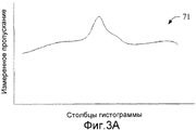
Фиг.3A иллюстрирует графическую зависимость между измеренными данными пропускания точечного источника и множеством столбцов гистограмм, в которые попадают соответственные данные.Fig. 3A illustrates a graphical relationship between the measured transmittance data of a point source and the plurality of histogram columns into which the corresponding data falls.
Фиг.3B иллюстрирует графическую зависимость между смоделированными или оцененными данными пропускания точечного источника, сформированными процессором с использованием алгоритма(ов) трассировки лучей, и множеством столбцов гистограмм, в которые попадают соответственные сымитированные данные.FIG. 3B illustrates a graphical relationship between simulated or estimated transmittance of a point source generated by a processor using a ray-tracing algorithm (s) and a plurality of histogram columns into which the corresponding simulated data falls.
Фиг.3C иллюстрирует графическую зависимость разности между значениями измеренных данных пропускания точечного источника и значениями сымитированных данных пропускания и множеством столбцов гистограмм, в которые попадают соответственные данные разности.Fig. 3C illustrates a graphical relationship of the difference between the values of the measured transmittance data of a point source and the values of the simulated transmittance data and the plurality of histogram columns into which the corresponding difference data falls.
Фиг.4 иллюстрирует способ формирования уточненной карты AC для внесения поправок на затухание в ядерном изображении в соответствии с различными аспектами, описанными в материалах настоящей заявки.Figure 4 illustrates a method for generating a refined AC map for attenuation correction in a nuclear image in accordance with various aspects described herein.
Фиг.5 иллюстрирует примерную систему стационарного лечебного учреждения, которая может включать в себя множество устройств формирования изображений, таких как устройство формирования изображений MR и ядерный сканер, которые формируют данные изображений, которые реконструируются индивидуальным или совместно используемым процессорами реконструкции для формирования трехмерных представлений изображений.FIG. 5 illustrates an exemplary inpatient hospital system, which may include a plurality of imaging devices, such as an MR imaging device and a nuclear scanner, that generate image data that is reconstructed by individual or shared reconstruction processors to generate three-dimensional image representations.
Фиг.1 иллюстрирует систему 10, в которой предусмотрено использование точечного или линейного источника(ов) для точной настройки карты затухания MR в соответствии с различными аспектами, описанными в материалах настоящей заявки. Устройство 12 формирования изображений или сканирования MR формирует основанное на MR изображение 14 анатомии субъекта или другого интересующего объема, из которого контур или контуры тела, легкое, мягкая ткань, костная структура, и т. д., может сегментироваться для формирования карты 16 коррекции затухания (AC) MR. Один или множество источников 18 излучения, например точечный источник излучения, размещены снаружи границы объекта (например, интересующего объема или пациента), но в пределах области исследования устройства 20 построения ядерных изображений. Данные 22 затухания или пропускания точечного источника измеряются с помощью устройства 20 построения ядерных изображений, такого как сканер PET или сканер однократной фотонной эмиссионной компьютерной томографии (SPECT). Отметим, что затухание и пропускание являются инверсией друг друга в том смысле, что подразумевается доля общего объема излучения, которая не поглощается (пропускается). Математически может использоваться любое из двух. В материалах настоящей заявки будут использоваться данные «пропускания», но должно быть понятно, что данные пропускания включают в себя информацию как о пропускании, так и о затухании. Из одиночного стационарного точечного источника может формироваться ядерное изображение 23 двухмерной проекции объекта или пациента. Между тем, оцененные данные 24 пропускания имитируются с использованием технологии или алгоритма 26 трассировки лучей, осуществляющих проецирование сквозь объем объекта с использованием карты 16 затухания MR. Измеренные данные 22 пропускания и сымитированные данные 24 пропускания точечного источника сравниваются программой 28 сравнения, а разность минимизируется алгоритмом 30 итерационной точной настройки, который выполняется над картой затухания. Подоптимальная карта 16 затухания MR, таким образом, может оптимизироваться с использованием измеренных данных пропускания точечного источника для формирования уточненной (например, оптимальной) карты 32 затухания MR.FIG. 1 illustrates a
Когда изображение MR сегментируется на разные типы ткани, может оцениваться каждый тип ткани и соответствующее свойство затухания излучения. Из изображения MR и оцененного значения пропускания для каждого сегмента можно рассчитывать оцененное пропускание по любому лучу через объект. Рассчитывается оцененное пропускание по каждому лучу фактически собранных данных пропускания точечного источника. Посредством сравнения оцененного и фактически измеренного пропускания по соответствующим лучам, могут определяться отклонения в оцененных значениях пропускания. Следует отметить, что множество лучей проходят через разные сегментированные области, а также через общие сегментированные области, но с разной длиной траекторий в каждой области. Области, оцененные как являющиеся воздухом или костью, могут легко верифицироваться. Более того, значение затухания/пропускания для каждой сегментированной области может уточняться итерационной точной настройкой коэффициентов затухания до тех пор, пока не будет оптимизировано соответствие между оцененным и фактически измеренным пропусканием по лучам из точечного источника.When an MR image is segmented into different types of tissue, each type of tissue and the corresponding radiation attenuation property can be evaluated. From the MR image and the estimated transmittance for each segment, the estimated transmittance for any beam through the object can be calculated. The estimated transmittance for each beam of the actually collected transmittance data of a point source is calculated. By comparing the estimated and actually measured transmittance from the respective beams, deviations in the estimated transmittance values can be determined. It should be noted that many rays pass through different segmented regions, as well as through common segmented regions, but with different path lengths in each region. Areas rated as being air or bone can be easily verified. Moreover, the attenuation / transmittance value for each segmented region can be refined by iteratively fine-tuning the attenuation coefficients until the correspondence between the estimated and actually measured transmittance by rays from a point source is optimized.
Аналогично, неспособность оптимизировать данные, которые не могут быть в пределах предварительного выбранного порогового значения, может указывать на движение пациента. Итерационная настройка положения контура тела и внутренних областей как единого целого, или положений внутренних областей в пределах контура тела может быть выполнена, чтобы оптимизировать соответствие и/или детектировать движение пациента.Similarly, failure to optimize data that cannot be within a preselected threshold value may indicate patient movement. Iterative adjustment of the position of the body contour and the internal regions as a whole, or the positions of the internal regions within the body contour can be performed in order to optimize the correspondence and / or to detect the movement of the patient.
Необходимо отметить, что устройство 12 формирования изображений MR и устройство 20 формирования ядерных изображений или сканирования могут быть отдельными устройствами формирования изображений или могут быть комбинацией или устройством формирования изображений двойного действия, в соответствии с различными вариантами осуществления. Например, случай формирователя изображений двойного действия, субъект сканируется с использованием способа формирования изображений MR, а затем, повторно сканируется с использованием способа формирования ядерных изображений (например, PET или SPECT) после того, как точечный источник был расположен в устройстве формирования изображений. Этим способом, движение субъекта может быть минимизировано между сканированиями. Дополнительно, в этом и других вариантах осуществления, положение точечного источника может сохраняться постоянным и/или может быть предопределенно, так что оно является согласованным между сканированиями формирования ядерных изображений, для того чтобы содействовать детектированию данных пропускания из них.It should be noted that the
Система 10 включает в себя память 34, которая хранит данные 14 изображения MR подоптимальную карту 16 AC, измеренные данные 22 точечного источника, сымитированные или оцененные данные 24 пропускания точечного источника и уточненную карту 32 AC. Память дополнительно хранит алгоритм(ы) 26 трассировки лучей, используемый для формирования сымитированных данных 24 пропускания, программу 28 сравнения (например, машинно-исполняемые команды для сравнения сымитированных данных с измеренными данными точечного источника) и алгоритм(ы) 30 итерационной точной настройки, используемый для уточнения карты 16 AC при формировании уточненной карты 32 AC.
Дополнительно, система 10 включает в себя процессор 36, который анализирует данные, хранимые в памяти 34, и выполняет алгоритмы, хранимые в памяти, для формирования новых данных для сохранения в памяти 34. Например, процессор выполняет один или более алгоритмов 38 реконструкции MR для реконструкции изображения 14 MR из необработанных данных 40 MR, собранных во время сканирования MR субъекта. Подобным образом, процессор выполняет один или более алгоритмов 39 реконструкции ядерного изображения для реконструкции ядерного изображения 23 проекции из необработанных данных 41 ядерного сканирования, собранных во время ядерного сканирования субъекта. Дополнительно, процессор выполняет алгоритмы трассировки лучей для формирования оцененных данных 24 пропускания, приводит в исполнение программу 28 сравнения для определения разности между оцененными данными 24 и измеренными данными 22 пропускания точечного источника, и выполняет алгоритм(ы) 30 итерационной точной настройки для формирования уточненной карты 32 AC из исходной карты 16 AC. Следует отметить, что «алгоритм», в качестве используемого в материалах настоящей заявки, может интерпретироваться означающим одну или более машинно-исполняемых команд, которые постоянно хранятся в памяти 34 и выполняются процессором 36.Additionally,
Таким образом, система 10 применяется для помещения точечного источника (или линейного источника) в области исследования формированием ядерных изображений с субъектом. В одном из примеров, точечный или линейный источник излучения является радиоизотопом с энергией, иной, чем у изотопа PET, используемого для формирования изображения PET субъекта, чтобы облегчать разграничение между изотопом формирования изображений и точечным или линейным источником. Излучение из точечного или линейного источника детектируется детекторами PET, отдельно от данных PET с использованием алгоритмов 42 разграничения энергии (например, хранимых в памяти 34 и выполняемых процессором 36), и используется для формирования данных излучения пропускания, более точно, проекции через субъект. Посредством использования двух или более источников излучения, либо посредством поворачивания источника излучения относительно пациента, без труда формируется трехмерная карта затухания излучения. Точечный или линейный источник может быть временно вставлен в портал или устройство 20 формирования ядерных изображений, либо конструкцию опоры пациента, или может быть постоянно смонтированным. Например, приемная конструкция может быть определена в предварительно выбранном известном местоположении на опоре пациента или конструкции, которая определяет диаметр в свету. Известное местоположение источника облегчает анализ данных проекции. В качестве альтернативы, местоположение источника может определяться посредством анализа данных проекции.Thus, the
Согласно еще одному варианту осуществления, карта затухания выводится из способа формирования анатомических изображений, такого как сканер 12 MR. Множество точечных источников 18, в частности, могут применяться для получения лучших рабочих характеристик. В последующем примере, однако, описана комбинация PET/MR с одиночным точечным источником. Согласно примеру, изображение MR объекта или пациента формируется с использованием сканера 12 MR. Устанавливается контур тела и другие границы внутренних органов. Области, известные по существу или полностью являющимися мягкой тканью, идентифицируются и помечаются. Нехарактеризуемая область(и), такая как легочная ткань, которая включает в себя воздух, и костная ткань, остается непомеченной.According to another embodiment, the attenuation map is derived from an anatomical imaging method, such as an
Создается ядерное изображение (например, PET или SPECT) того же самого объекта или пациента (например, собираются ядерные данные изображения). Одновременно, открывается другое энергетическое окно для приема импульсов счета из радиоактивного точечного источника 18, надлежащим образом расположенного вне границ пациента или объекта, но в пределах области исследования в портале формирователя ядерных изображений. Например, стандартное энергетическое окно используется для формирования изображений SPECT, а энергетическое окно и «черепичный» режим используется для формирования изображений PET. Точечный источник имеет более высокую энергию, чем данные испускания, сформированные по радиоактивному изотопу, используемому для формирования изображения пациента или объекта (например, 137Cs на 662 килоэлектронвольтах при формировании изображения данных PET на 511 килоэлектронвольтах). Контур или очертание тела дополнительно содействует проведению различия излучения точечного источника от рассеяния. Дополнительно, использование точечного источника с энергией, более высокой, чем излучение PET, облегчает проведение различий излучения точечного источника от рассеяния излучения PET, поскольку излучение точечного источника не перекрывается с рассеянием излучения PET боле низкой энергии. Данные из источника(ов) собираются и накапливаются в гистограмму или проекцию, которая сохраняется в памяти 34. Коэффициенты затухания назначаются (например, процессором при формировании карты 16 AC) известным областям сегментированного изображения MR. Математическая модель строится с использованием алгоритма трассировки лучей для формирования оцененных данных 24 проекции посредством основанной на MR карты 16 затухания с такой же геометрией, как у внешнего точечного источника (смотрите фиг.2). Неизвестным областям присваиваются значения воздуха или кости, альтернативно, до тех пор, пока оцененные или сымитированные математические данные 24 проекции посредством карты 16 затухания не соответствуют близко измеренным данным 22 пропускания точечного источника. Уточненная карта 32 AC, надлежащим образом сегментированная и с надлежащим образом присвоенными значениями для различных неопределенных областей воздуха или костной ткани, может использоваться для выполнения коррекции затухания ядерного изображения 23. Как только определены воздушные или костные области, по выбору оптимизируются коэффициенты затухания для различных областей мягких тканей.A nuclear image (for example, PET or SPECT) of the same object or patient is created (for example, nuclear image data is collected). At the same time, another energy window opens for receiving count pulses from a
Фиг.2 иллюстрирует точечный источник 18, расположенный в устройстве 20 формирования ядерного изображения, в соответствии с одним или более аспектов, описанных в материалах настоящей заявки. Интересующий объем 60 (например, объект, пациент) помещается на стол или опору 62 пациента в области формирования изображений, определенной порталом 64 устройства 20 формирования ядерных изображений. Интересующий объем имеет неопределенную область 66, которая может быть костной тканью или воздухом (например, легочной тканью, воздушным или газовым карманом, и т. д.), которые не могут быть без труда подвергнуты устранению неоднозначности с использованием изображения MR интересующего объема. Соответственно, точечный источник 18 расположен близко на столе 62 возле интересующего объема и испускает радиоактивные линии 68 пропускания, которые детектируются ядерными детекторами 70, установленными на портал 64. В одном из вариантов осуществления, портал 64 является поворачиваемым порталом, и ядерные детекторы 70 поворачиваются вокруг области исследования для детектирования линий 68 пропускания, а также для сбора ядерных данных сканирования от радиоактивного изотопа, введенного в интересующий объем, для того чтобы формировать его ядерное изображение.FIG. 2 illustrates a
В еще одном варианте осуществления, два или более точечных источника 18, 18', имеющих разные энергии энергий пропускания, разнесены вокруг области исследования, чтобы создавать полное поле зрения. Этим способом, два или более линейных интегралов формируются для содействия разрешению неопределенностью между костными и воздушными элементами объемного изображения в данных изображения MR.In yet another embodiment, two or
В еще одном варианте осуществления, ядерные детекторы 70 являются детекторами PET, а затухание в собранных данных PET корректируется с использованием описанной в материалах настоящей заявки уточненной карты AC при реконструкции изображения PET.In yet another embodiment, the nuclear detectors 70 are PET detectors, and the attenuation in the collected PET data is corrected using the refined AC map described herein for reconstructing the PET image.
В еще одном варианте осуществления, ядерные детекторы 70 являются одиночными детекторами однофотонной позитрон-эмиссионой компьютерной томографии (SPECT), а затухание в собранных данных SPECT корректируется с использованием описанной в материалах настоящей заявки уточненной карты AC при реконструкции изображения SPECT.In yet another embodiment, the nuclear detectors 70 are single-photon positron emission computed tomography (SPECT) detectors, and the attenuation in the collected SPECT data is corrected using the refined AC map described herein for reconstructing the SPECT image.
Фиг.3A иллюстрирует графическую зависимость 71 между измеренными данными 22 пропускания точечного источника и множеством столбцов гистограмм, в которые попадают соответственные данные. Измеренные данные 22 пропускания точечного источника измеряются в соединении с оцененными данными 24 пропускания точечного источника (фиг.3B), чтобы итерационно уточнять карту AC до тех пор, пока она не готова, чтобы использоваться для коррекции затухания PET.FIG. 3A illustrates a
Фиг.3B иллюстрирует графическую зависимость 72 между смоделированными или оцененными данными 24 пропускания точечного источника, сформированными процессором с использованием алгоритма(ов) 26 (фиг.1) трассировки лучей, и множеством столбцов гистограмм, в которые попадают соответственные сымитированные данные. Оцененные данные 24 пропускания точечного источника сравниваются с измеренными данными 22 точечного источника, и должны определять, готова ли карта AC для использования при внесении поправок на затухание в данные сканирования PET при реконструкции изображения PET.FIG. 3B illustrates a
Фиг.3C иллюстрирует графическую зависимость 71 разности между значениями измеренных данных пропускания точечного источника и значениями сымитированных данных пропускания и множеством столбцов гистограмм, в которые попадают соответственные данные разности. Значения разности определяются, когда процессор 36 приводит в исполнение программу 28 сравнения по фиг.1. С каждой итерационной настройкой в отношении карты AC, значения разности уменьшаются. Как только значения разности между оцененными и измеренными данными пропускания достаточно малы (например, ниже предопределенного порогового значения), уточненная карта AC сохраняется для использования при коррекции затухания PET.3C illustrates a
Фиг.4 иллюстрирует способ формирования уточненной карты AC для внесения поправок на затухание в ядерном изображении в соответствии с различными аспектами, описанными в материалах настоящей заявки. На 78 формируется изображение MR субъекта. На 80 карта AC формируется из сегментированного изображения MR субъекта. На 82 субъект помещается в области исследования ядерного сканера (например, PET или SPECT) с точечным источником, расположенным вне субъекта и в пределах области исследования. Точечный источник испускает гамма-лучи с энергией, более высокой, чем у радиоактивного изотопа (например, 511 килоэлектронвольт), введенного в субъект, такого как 137Cs (например, приблизительно 662 килоэлектронвольта). В качестве альтернативы, более низкая энергия (например, более низкая чем 511 килоэлектронвольт) используется для точечного источника, такого как 133Ba (например, приблизительно 360 килоэлектронвольт).Figure 4 illustrates a method for generating a refined AC map for attenuation correction in a nuclear image in accordance with various aspects described herein. At 78, an MR image of the subject is formed. At 80, an AC card is formed from a segmented MR image of a subject. At 82, a subject is placed in a nuclear scanner study area (e.g., PET or SPECT) with a point source located outside the subject and within the study area. A point source emits gamma rays with an energy higher than that of a radioactive isotope (e.g., 511 kiloelectron-volts) introduced into a subject, such as 137 Cs (e.g., approximately 662 kiloelectron-volts). Alternatively, lower energy (e.g., lower than 511 kiloelectron-volts) is used for a point source such as 133 Ba (e.g., approximately 360 kiloelectron-volts).
На 84 данные пропускания из точечного источника измеряются с использованием ядерного сканера и формируются ядерные данные изображения субъекта. Например, сканер PET, работающий в черепичном режиме, может измерять данные пропускания точечного источника в тот же самый момент, что и данные испускания ядерного изотопа, такие как показанные на фиг. 3A. На 86 данные пропускания выводятся или оцениваются с использованием технологии трассировки лучей на карте AC, такие как показанные на фиг.3B.At 84, transmittance data from a point source is measured using a nuclear scanner and nuclear subject image data is generated. For example, a tiled-mode PET scanner can measure the transmittance of a point source at the same time as the nuclear isotope emission data, such as those shown in FIG. 3A. At 86, transmittance data is derived or estimated using ray tracing technology on an AC card, such as those shown in FIG. 3B.
На 88 определяется разница между данными пропускания из 84 и данными проекции из 86, как показано на фиг.3C.At 88, the difference between the transmission data from 84 and the projection data from 86 is determined, as shown in FIG. 3C.
На 90 вычисляется коэффициент отклонения, представляющий разность, определенную на 88, такую как среднеквадратическое (rms) отклонение, или тому подобное.At 90, a deviation coefficient is calculated representing a difference determined at 88, such as a standard deviation (rms) deviation, or the like.
На 92 карта затухания модифицируется с использованием коэффициента, определенного на 90, и способ возвращается на этап 86 для формирования следующего элемента данных проекции, сравнения с измеренными данными пропускания, определения разницы и формирования среднеквадратического коэффициента. Как только получены два значения среднеквадратического отклонения, они сравниваются на 94. На 96 производится определение касательно того, было ли найдено минимальное среднеквадратическое отклонение. Если нет, способ возвращается на этап 92. В случае положительного ответа, уточненная карта затухания сохраняется, на 97, для использования при внесении поправок на затухание в ядерном изображении субъекта, сформированном на 84. На 98 ядерные данные изображения, сформированные на 84, реконструируются с использованием карты AC, сохраненной на 97, для формирования скорректированного затуханием ядерного изображения (например, PET или SPECT).At 92, the attenuation map is modified using a coefficient determined at 90, and the method returns to step 86 to form the next projection data element, compare it with the measured transmittance data, determine the difference, and generate the root mean square coefficient. Once two standard deviations are obtained, they are compared at 94. At 96, a determination is made as to whether the minimum standard deviation has been found. If not, the method returns to step 92. If the answer is yes, the updated attenuation map is stored, at 97, for use in making attenuation adjustments in the subject's nuclear image formed at 84. At 98, the nuclear image data generated at 84 is reconstructed from using an AC card stored at 97 to form a fade-corrected nuclear image (e.g., PET or SPECT).
Как показано на фиг.5, примерная система 100 стационарного лечебного учреждения может включать в себя множество устройств формирования изображений, таких как устройство 12 формирования изображений MR, ядерный сканер 20 (например, PET или SPECT), или тому подобное, которые формируют данные изображений, которые реконструируются индивидуальным или совместно используемым процессорами 102 реконструкции для формирования трехмерных представлений изображений. Представления изображений передаются через сеть 104 в центральную память 106 или локальную память 108.As shown in FIG. 5, an exemplary
На станции 110, соединенной с сетью, оператор использует пользовательский интерфейс 124 для перемещения выбранной трехмерной карты затухания MR пациента в или между центральной памятью 106 и локальной памятью 108. Видеопроцессор 116 отображает выбранную карту затухания (или изображение MR) в первом окне 1181 просмотра устройства 122 отображения. Ядерное изображение отображается во втором окне 1182 просмотра. Третье окно 1183 просмотра может отображать наложение карты затухания и ядерного изображения. Например, пользователю может быть дана возможность совмещать ориентиры в карте затухания MR с соответствующими структурами или ориентирами в ядерном изображении. Например, оператор, через интерфейс 124, выбирает ориентиры ядерного изображения (например, с использованием мыши, пера или другого пригодного устройства пользовательского ввода), которые соответствуют ориентирам в изображении карты затухания. В качестве альтернативы, карта затухания может выравниваться автоматически, программой в процессоре 116. Процессор 36 (фиг.1) в пользовательском интерфейсе 124 затем выполняет алгоритмы коррекции и делает вывод о надлежащем типе ткани (например, кости или воздухе) для применения при заполнении неоднозначных зон в карте затухания.At
Уточненная карта затухания затем может использоваться для реконструкции скорректированного затуханием ядерного изображения, которое может использоваться в других применениях. Например, станция 130 планирования лечения может использовать скорректированное затуханием изображение PET для планирования сеанса лечения. Как только удовлетворяющая оператора терапия запланирована, она в тех случаях, когда такая терапия соответствует автоматической процедуре, может передаваться на терапевтическое устройство 132, которое реализует запланированный сеанс. Другие станции могут использовать скорректированное затуханием изображение PET в различных других процессах планирования.The updated attenuation map can then be used to reconstruct the attenuation-corrected nuclear image, which can be used in other applications. For example,
В еще одном варианте осуществления, наложение, отображенное в окне 1183 просмотра, является настраиваемым для взвешивания изображения MR относительно ядерного изображения, или наоборот. Например, линейка или кнопка ползунка (не показаны), которые могут быть механическими или представляться на устройстве 122 отображения и подвергаться манипуляциям устройством ввода, могут настраиваться, чтобы изменять вес изображения MR или ядерного изображения. В одном из примеров, оператор может настраивать изображение в окне 1183 просмотра от данных изображения чисто MR (показанных в окне 1181 просмотра), через многочисленные и непрерывные комбинации данных изображения MR и ядерного изображения, до чисто ядерных данных изображения (показанного в окне 1182 просмотра). Например, отношение данных изображения MR к ядерным данным изображения может дискретно или непрерывно настраиваться от 0:1 до 1:0. В качестве еще одного варианта выбора, изображение MR может отображаться в шкале уровней серого, а ядерное изображение может быть цветным. Анатомические ориентиры в изображении MR помогают соотносить ядерное изображение с субъектом.In yet another embodiment, the overlay displayed in the viewing window 118 3 is customizable to weight the MR image relative to the nuclear image, or vice versa. For example, a ruler or slider button (not shown), which may be mechanical or appear on the
Изобретение было описано со ссылкой на несколько вариантов осуществления. После прочтения и осмысления специалисту будут очевидны модификации и изменения предшествующего подробного описания. Предполагается, что изобретение будет истолковываться в качестве включающего в себя все такие модификации и изменения, насколько они подпадают под объем прилагаемой формулы изобретения или ее эквивалентов.The invention has been described with reference to several embodiments. After reading and comprehension to the specialist, modifications and changes to the foregoing detailed description will be apparent. It is intended that the invention be construed as including all such modifications and changes to the extent that they fall within the scope of the appended claims or their equivalents.
Claims (15)
формирователь (12) изображений магнитного резонанса (MR), который получает данные (14) изображения MR субъекта (60) во время сканирования для сбора данных MR;
ядерный сканер (20), который получает ядерные данные (23) изображения субъекта (60) в течение сканирования для сбора ядерных данных, и одновременно измеряет данные (22) пропускания из источника (18) излучения, расположенного в области исследования ядерного сканера (20); и
процессор, который:
формирует карту (16) коррекции затухания (AC) из данных (14) изображения MR;
итерационно уточняет карту (16) AC, чтобы сформировать уточненную карту (32) AC с использованием измеренных данных пропускания (22); и
корректирует в ядерные данные (23) изображения с учетом затухания с использованием уточненной карты (32) AC.1. The system (10) of the correction of anatomical images, including:
a magnetic resonance imaging (MR) imager (12) that receives the MR image data (14) of the subject (60) during scanning to collect MR data;
a nuclear scanner (20) that receives nuclear data (23) of the image of the subject (60) during the scan to collect nuclear data, and at the same time measures transmission data (22) from a radiation source (18) located in the area of research of the nuclear scanner (20) ; and
a processor that:
forms a card (16) attenuation correction (AC) from the data (14) of the MR image;
iteratively refines the AC map (16) to form an updated AC map (32) using the measured transmission data (22); and
corrects the image data in the nuclear data (23) taking into account the attenuation using the updated AC map (32).
алгоритм (26) трассировки лучей с учетом карты (16) AC для формирования оцененных данных пропускания (24);
сравнение (28), которое определяет разность между оцененными данными (24) пропускания и измеренными данными (22) пропускания; и
настройку значений затухания в карте AC для уменьшения разности между оцененными и измеренными данными пропускания.2. The system according to claim 1, in which the processor (36) performs:
ray tracing algorithm (26) taking into account the AC map (16) to generate estimated transmission data (24);
a comparison (28) that determines the difference between the estimated transmittance data (24) and the measured transmittance data (22); and
setting attenuation values in the AC card to reduce the difference between the estimated and measured transmittance data.
опоре (62) пациента, на которой расположен субъект (60), в области исследования портала (64) ядерного сканера (20); и
портале (64).6. The system according to claim 1, in which the radiation source (18) is installed in a fixed place on or in at least one of the following:
the support (62) of the patient, on which the subject is located (60), in the field of research of the portal (64) of the nuclear scanner (20); and
portal (64).
формируют карту (16) коррекции затухания (AC) из данных (14) изображения MR субъекта (60);
пропускают излучение из источника (18) излучения через субъект (60), источник излучения является расположенным вне субъекта;
измеряют данные (22) пропускания, основываясь на излучении, пропущенном через субъект;
формируют оцененные данные (24) пропускания из карты (16) AC; и
формируют уточненную карту (32) AC посредством настройки карты (16) AC на основании сравнения измеренных данных (22) пропускания и оцененных данных (24) пропускания.7. The method of updating the card attenuation correction (AC) magnetic resonance (MR), which consists in the fact that:
forming a card (16) attenuation correction (AC) from the data (14) of the MR image of the subject (60);
transmit radiation from the radiation source (18) through the subject (60), the radiation source is located outside the subject;
measuring transmission data (22) based on radiation transmitted through the subject;
generating estimated transmission data (24) from the AC card (16); and
an updated AC card (32) is formed by setting the AC card (16) based on a comparison of the measured transmission data (22) and the estimated transmission data (24).
формируют данные позитрон-эмиссионной томографии (PET);
корректируют данные PET с помощью уточненной карты AC; и
реконструируют скорректированные данные PET в изображение PET.8. The method according to claim 7, further comprising:
generate positron emission tomography (PET) data;
correct PET data with a refined AC card; and
reconstruct the corrected PET data into a PET image.
определяют первое расхождение между измеренными данными пропускания и оцененными данными пропускания;
настраивают карту (16) AC для уменьшения расхождения;
определяют вторые оцененные данные пропускания с использованием настроенной карты AC;
определяют второе расхождение между измеренными данными пропускания и вторыми оцененными данными пропускания; и
дополнительно настраивают карту (16) AC для дальнейшего уменьшения расхождения.9. The method according to claim 7, further comprising:
determining a first discrepancy between the measured transmission data and the estimated transmission data;
tune the AC card (16) to reduce discrepancies;
determining second estimated transmission data using a configured AC card;
determining a second discrepancy between the measured transmission data and the second estimated transmission data; and
optionally configure the AC card (16) to further reduce the discrepancy.
итерационно определяют среднеквадратические (rms) значения и настраивают карту (16) AC до тех пор, пока определенные среднеквадратические значения не оптимизированы.10. The method according to claim 9, in which the determination of the discrepancy is that:
iteratively determine the rms values and adjust the (16) AC map until certain rms values are optimized.
кольцо детекторов (70) излучения;
источник (18) излучения, стационарно установленный в пределах кольца детекторов излучения;
процессор (36), запрограммированный для выполнения способа по п.7, чтобы формировать уточненную карту (32) коррекции затухания (AC).
алгоритм (39) реконструкции, который корректирует данные PET из детекторов (70) излучения с помощью уточненной карты (32) AC и реконструирует скорректированные данные PET в подвергнутое коррекции затухания изображение PET.13. A positron emission tomography (PET) scanner, including:
ring of radiation detectors (70);
a radiation source (18) permanently mounted within the ring of radiation detectors;
a processor (36) programmed to perform the method according to claim 7 in order to generate an updated attenuation correction (AC) map (32).
a reconstruction algorithm (39) that corrects PET data from radiation detectors (70) using a refined map (32) AC and reconstructs the corrected PET data into a attenuated PET image.
множество детекторов (70) излучения;
источник (18) излучения, стационарно установленный в пределах области исследования детекторов излучения;
процессор (36), запрограммированный для выполнения способа по п.7, чтобы формировать уточненную карту (32) коррекции затухания (AC).
алгоритм (39) реконструкции, который корректирует данные SPECT из детекторов (70) излучения с помощью уточненной карты (32) AC и реконструирует скорректированные данные PET в подвергнутое коррекции затухания изображение SPECT.14. A single-photon emission computed tomography (SPECT) scanner, including:
a plurality of radiation detectors (70);
a radiation source (18) permanently installed within the study area of radiation detectors;
a processor (36) programmed to perform the method according to claim 7 in order to generate an updated attenuation correction (AC) map (32).
a reconstruction algorithm (39) that corrects the SPECT data from the radiation detectors (70) using the updated AC map (32) and reconstructs the corrected PET data into the SPECT image subjected to attenuation correction.
формируют карту (16) AC из собранных данных (14) изображения магнитного резонанса (MR);
проводят различие между костными и воздушными элементами объемного изображения в данных (14) изображения MR с использованием данных пропускания, детектированных из радиоактивного точечного источника (18); и
обновляют карту (16) AC на основании детектированных данных пропускания точечного источника. 15. The method of updating the card (16) attenuation correction (AC), which consists in the fact that:
forming an AC map (16) from the collected magnetic resonance image (MR) data (14);
distinguishing between bone and airborne image elements in the MR image data (14) using transmission data detected from a radioactive point source (18); and
update the AC map (16) based on the detected point source transmission data.
Applications Claiming Priority (3)
| Application Number | Priority Date | Filing Date | Title |
|---|---|---|---|
| US9755508P | 2008-09-17 | 2008-09-17 | |
| US61/097,555 | 2008-09-17 | ||
| PCT/IB2009/053944 WO2010032167A2 (en) | 2008-09-17 | 2009-09-09 | Mr segmentation using transmission data in hybrid nuclear/mr imaging |
Publications (2)
| Publication Number | Publication Date |
|---|---|
| RU2011115056A RU2011115056A (en) | 2012-10-27 |
| RU2504841C2 true RU2504841C2 (en) | 2014-01-20 |
Family
ID=42039963
Family Applications (1)
| Application Number | Title | Priority Date | Filing Date |
|---|---|---|---|
| RU2011115056/08A RU2504841C2 (en) | 2008-09-17 | 2009-09-09 | Segmentation of magnetic resonance using transmission data when forming hybrid nuclear/magnetic resonance images |
Country Status (6)
| Country | Link |
|---|---|
| US (1) | US8406495B2 (en) |
| EP (1) | EP2338142A2 (en) |
| JP (1) | JP5385394B2 (en) |
| CN (1) | CN102265307B (en) |
| RU (1) | RU2504841C2 (en) |
| WO (1) | WO2010032167A2 (en) |
Families Citing this family (23)
| Publication number | Priority date | Publication date | Assignee | Title |
|---|---|---|---|---|
| US8218848B2 (en) * | 2008-07-23 | 2012-07-10 | Siemens Aktiengesellschaft | System and method for the generation of attenuation correction maps from MR images |
| DE102008047840B4 (en) * | 2008-09-18 | 2018-08-30 | Siemens Healthcare Gmbh | Method for the at least partial determination and / or adaptation of an attenuation map used for the attenuation correction of positron emission tomography image data sets in a combined magnetic resonance positron emission tomography device |
| WO2012120422A1 (en) * | 2011-03-07 | 2012-09-13 | Koninklijke Philips Electronics N.V. | Mr segmentation using nuclear emission data in hybrid nuclear imaging/mr |
| CN103458790A (en) * | 2011-03-17 | 2013-12-18 | 皇家飞利浦有限公司 | Multiple modality cardiac imaging |
| WO2012160520A1 (en) * | 2011-05-24 | 2012-11-29 | Koninklijke Philips Electronics N.V. | Apparatus for generating assignments between image regions of an image and element classes |
| EP2814395B1 (en) | 2012-02-16 | 2017-08-23 | Koninklijke Philips N.V. | Spatially corrected nuclear image reconstruction |
| US9204817B2 (en) * | 2012-04-19 | 2015-12-08 | General Electric Company | Attenuation correction in positron emission tomography using magnetic resonance imaging |
| US9063237B2 (en) * | 2012-05-08 | 2015-06-23 | Koninklijke Philips N.V. | SPECT/PET imaging system |
| KR101350496B1 (en) * | 2012-05-22 | 2014-01-16 | 서울대학교산학협력단 | Method to generate a attenuation map of emission tomography and MRI combined imaging system |
| US8923592B2 (en) * | 2012-05-29 | 2014-12-30 | General Electric Company | Methods and systems for performing attenuation correction |
| US8867814B2 (en) * | 2012-10-04 | 2014-10-21 | General Electric Company | Methods and systems for generating a positron emission tomography attenuation correction map |
| US9002082B2 (en) | 2012-12-27 | 2015-04-07 | General Electric Company | Axially varying truncation completion for MR-based attenuation correction for PET/MR |
| US9364192B2 (en) * | 2013-03-15 | 2016-06-14 | Siemens Medical Solutions Usa, Inc. | Error estimates in quantitative functional imaging |
| RU2523929C1 (en) * | 2013-03-18 | 2014-07-27 | Корпорация "САМСУНГ ЭЛЕКТРОНИКС Ко., Лтд." | System and method for automated planning of views in 3d brain images |
| US9311707B2 (en) * | 2013-09-27 | 2016-04-12 | General Electric Company | System and method for attenuation correction of phantom images |
| DE112015002809T5 (en) * | 2014-06-13 | 2017-03-16 | Siemens Medical Solutions Usa, Inc. | Multiple emission energies in single-photon emission computed tomography |
| US20160066874A1 (en) * | 2014-09-10 | 2016-03-10 | The General Hospital Corporation | Attenuation correction of positron emission tomography data using magnetic resonance images depicting bone density variations |
| JP6467221B2 (en) * | 2014-12-22 | 2019-02-06 | キヤノン株式会社 | Image processing apparatus and method |
| US9508165B1 (en) * | 2015-06-30 | 2016-11-29 | General Electric Company | Systems and methods for peak tracking and gain adjustment |
| CN108351396B (en) * | 2015-11-02 | 2021-09-14 | 皇家飞利浦有限公司 | Method, computer program product and magnetic resonance imaging system for tissue classification |
| US10210634B2 (en) * | 2016-07-20 | 2019-02-19 | Shanghai United Imaging Healthcare Co., Ltd. | System and method for segmenting medical image |
| CA3134284C (en) * | 2018-03-07 | 2023-08-29 | Siemens Medical Solutions Usa, Inc. | Calibration bias reduction in a pressurized gas ion chamber-based dose calibrator |
| CN109308728B (en) * | 2018-10-25 | 2023-01-03 | 上海联影医疗科技股份有限公司 | Positron emission computed tomography image processing method and device |
Citations (5)
| Publication number | Priority date | Publication date | Assignee | Title |
|---|---|---|---|---|
| US20060004274A1 (en) * | 2004-06-30 | 2006-01-05 | Hawman Eric G | Fusing nuclear medical images with a second imaging modality |
| US20060237652A1 (en) * | 2000-08-21 | 2006-10-26 | Yoav Kimchy | Apparatus and methods for imaging and attenuation correction |
| US20070221850A1 (en) * | 2006-03-23 | 2007-09-27 | Vladimir Panin | Attenuation correction for nuclear medical imaging scanners with simultaneous transmission and emission acquisition |
| US20080135769A1 (en) * | 2006-11-22 | 2008-06-12 | Rosen Bruce R | Attenuation correction of pet image using image data acquired with an mri system |
| RU2007101297A (en) * | 2004-06-25 | 2008-07-27 | Медисим Нв (Be) | METHOD FOR DEVELOPING A THERAPEUTIC PROGRAM OF ORTHOLOGIC SURGERY AND RELATED DEVICES |
Family Cites Families (17)
| Publication number | Priority date | Publication date | Assignee | Title |
|---|---|---|---|---|
| US5376795A (en) * | 1990-07-09 | 1994-12-27 | Regents Of The University Of California | Emission-transmission imaging system using single energy and dual energy transmission and radionuclide emission data |
| US5449913A (en) | 1993-11-03 | 1995-09-12 | Chang; Wei | Apparatus for producing attenuation scan |
| US5672877A (en) * | 1996-03-27 | 1997-09-30 | Adac Laboratories | Coregistration of multi-modality data in a medical imaging system |
| WO1999056150A1 (en) | 1998-04-27 | 1999-11-04 | Duke University | Transmission scanning technique for gamma camera coincidence imaging |
| US6310968B1 (en) * | 1998-11-24 | 2001-10-30 | Picker International, Inc. | Source-assisted attenuation correction for emission computed tomography |
| US6628983B1 (en) * | 2000-10-25 | 2003-09-30 | Koninklijke Philips Electronics N.V. | Nuclear imaging systems and methods with feature-enhanced transmission imaging |
| TW542993B (en) | 2001-07-12 | 2003-07-21 | Inst Information Industry | Multi-dimension and multi-algorithm document classifying method and system |
| DE10231061A1 (en) * | 2002-07-10 | 2004-01-22 | Philips Intellectual Property & Standards Gmbh | Process and system for improving the information content in an image |
| US7197171B2 (en) * | 2003-02-19 | 2007-03-27 | Elgems Ltd. | Nuclear imaging |
| US8108024B2 (en) * | 2004-12-15 | 2012-01-31 | Koninklijke Philips Electronics N.V. | Registration of multi-modality images |
| CN101378805B (en) * | 2005-10-17 | 2013-03-27 | 艾伯塔健康服务中心 | Integrated external beam radiotherapy and MRI system |
| US7402807B2 (en) | 2005-11-02 | 2008-07-22 | Siemens Medical Solutions Usa, Inc. | Method for reducing an electronic time coincidence window in positron emission tomography |
| US7348564B2 (en) | 2005-12-12 | 2008-03-25 | General Electric Company | Multi modality imaging methods and apparatus |
| DE102006046287A1 (en) * | 2006-09-29 | 2008-04-03 | Siemens Ag | Magnetic resonance-positron emissions tomography field generating unit for representation of tissue in human or animal body, has movable resting board in examination channel and main magnet for generating constant magnetic field |
| JP4584232B2 (en) * | 2006-11-27 | 2010-11-17 | 富士フイルムRiファーマ株式会社 | Brain model |
| DE102007034953B4 (en) * | 2007-07-26 | 2016-09-22 | Siemens Healthcare Gmbh | A method for recording movements of a patient and associated medical device |
| US8098916B2 (en) * | 2007-10-30 | 2012-01-17 | General Electric Company | System and method for image-based attenuation correction of PET/SPECT images |
-
2009
- 2009-09-09 RU RU2011115056/08A patent/RU2504841C2/en not_active IP Right Cessation
- 2009-09-09 CN CN200980136210.0A patent/CN102265307B/en not_active Expired - Fee Related
- 2009-09-09 WO PCT/IB2009/053944 patent/WO2010032167A2/en active Application Filing
- 2009-09-09 US US13/062,222 patent/US8406495B2/en not_active Expired - Fee Related
- 2009-09-09 JP JP2011526607A patent/JP5385394B2/en not_active Expired - Fee Related
- 2009-09-09 EP EP09787148A patent/EP2338142A2/en not_active Withdrawn
Patent Citations (5)
| Publication number | Priority date | Publication date | Assignee | Title |
|---|---|---|---|---|
| US20060237652A1 (en) * | 2000-08-21 | 2006-10-26 | Yoav Kimchy | Apparatus and methods for imaging and attenuation correction |
| RU2007101297A (en) * | 2004-06-25 | 2008-07-27 | Медисим Нв (Be) | METHOD FOR DEVELOPING A THERAPEUTIC PROGRAM OF ORTHOLOGIC SURGERY AND RELATED DEVICES |
| US20060004274A1 (en) * | 2004-06-30 | 2006-01-05 | Hawman Eric G | Fusing nuclear medical images with a second imaging modality |
| US20070221850A1 (en) * | 2006-03-23 | 2007-09-27 | Vladimir Panin | Attenuation correction for nuclear medical imaging scanners with simultaneous transmission and emission acquisition |
| US20080135769A1 (en) * | 2006-11-22 | 2008-06-12 | Rosen Bruce R | Attenuation correction of pet image using image data acquired with an mri system |
Non-Patent Citations (2)
| Title |
|---|
| ZAIDI H. et al, "Determination of the attenuation map in emission tomography", The Journal of Nuclear Medicine, vol. 44, No.2, 01.02.2003. * |
| ZAIDI H. et al, "Determination of the attenuation map in emission tomography", The Journal of Nuclear Medicine, vol. 44, №2, 01.02.2003. * |
Also Published As
| Publication number | Publication date |
|---|---|
| WO2010032167A2 (en) | 2010-03-25 |
| US20110164801A1 (en) | 2011-07-07 |
| JP2012503177A (en) | 2012-02-02 |
| CN102265307A (en) | 2011-11-30 |
| US8406495B2 (en) | 2013-03-26 |
| EP2338142A2 (en) | 2011-06-29 |
| JP5385394B2 (en) | 2014-01-08 |
| WO2010032167A3 (en) | 2011-04-21 |
| RU2011115056A (en) | 2012-10-27 |
| CN102265307B (en) | 2014-10-22 |
Similar Documents
| Publication | Publication Date | Title |
|---|---|---|
| RU2504841C2 (en) | Segmentation of magnetic resonance using transmission data when forming hybrid nuclear/magnetic resonance images | |
| CN109741284B (en) | System and method for correcting respiratory motion-induced mismatches in PET imaging | |
| CN102711617B (en) | Scan plan field of view adjustor, determiner, and/or quality assessor | |
| JP5643772B2 (en) | MR coil attenuation correction in hybrid PET / MR system | |
| CN106456098B (en) | The generation method and system of decay pattern | |
| US20180374205A1 (en) | System and method for image calibration | |
| US9140803B2 (en) | Acquisition protocol assessment apparatus | |
| CN109060849B (en) | Method, system and device for determining radiation dose modulation line | |
| US20130267841A1 (en) | Extracting Application Dependent Extra Modal Information from an Anatomical Imaging Modality for use in Reconstruction of Functional Imaging Data | |
| US20220061781A1 (en) | Systems and methods for positioning | |
| US10925554B2 (en) | Outside-FOV activity estimation using surview and prior patient data in positron emission tomography | |
| JP2011521224A (en) | Use of non-attenuated corrected PET emission images to compensate for imperfect anatomical images | |
| CN103315760A (en) | Systems and methods for attenuation compensation in nuclear medicine imaging based on emission data | |
| US20210110594A1 (en) | Synthetic Parameterized Computed Tomography from Surface Data in Medical Imaging | |
| US9734574B2 (en) | Image processor, treatment system, and image processing method | |
| US11813103B2 (en) | Methods and systems for modulating radiation dose | |
| CN107635469A (en) | The estimation of the decay pattern met based on the scattering in PET system | |
| CN109124666A (en) | A kind of mthods, systems and devices of determining dose of radiation modulation lines | |
| CN109077746B (en) | Method, system and device for determining radiation dose modulation line | |
| US11538160B2 (en) | Systems and methods for scatter correction of image | |
| US20230083704A1 (en) | Systems and methods for determining examination parameters | |
| Chen et al. | Low dose cone-beam computed tomography reconstruction via hybrid prior contour based total variation regularization (hybrid-PCTV) | |
| US20210090291A1 (en) | System and method for diagnosis and treatment | |
| US20230056685A1 (en) | Methods and apparatus for deep learning based image attenuation correction | |
| CN115222605A (en) | Image imaging method and system |
Legal Events
| Date | Code | Title | Description |
|---|---|---|---|
| MM4A | The patent is invalid due to non-payment of fees |
Effective date: 20150910 |