RU2499251C2 - X-ray inspection by simultaneous imaging based on transmission and back scattering of light - Google Patents
X-ray inspection by simultaneous imaging based on transmission and back scattering of light Download PDFInfo
- Publication number
- RU2499251C2 RU2499251C2 RU2011148960/28A RU2011148960A RU2499251C2 RU 2499251 C2 RU2499251 C2 RU 2499251C2 RU 2011148960/28 A RU2011148960/28 A RU 2011148960/28A RU 2011148960 A RU2011148960 A RU 2011148960A RU 2499251 C2 RU2499251 C2 RU 2499251C2
- Authority
- RU
- Russia
- Prior art keywords
- scattering
- penetrating radiation
- radiation
- signal
- partition
- Prior art date
Links
- 230000005540 biological transmission Effects 0.000 title claims abstract description 37
- 238000003384 imaging method Methods 0.000 title description 18
- 238000007689 inspection Methods 0.000 title description 3
- 230000005855 radiation Effects 0.000 claims abstract description 90
- 230000000149 penetrating effect Effects 0.000 claims abstract description 50
- 238000000034 method Methods 0.000 claims abstract description 28
- 230000001678 irradiating effect Effects 0.000 claims abstract description 4
- 238000001514 detection method Methods 0.000 claims description 30
- 238000005192 partition Methods 0.000 claims description 26
- 230000009467 reduction Effects 0.000 claims description 8
- 238000012937 correction Methods 0.000 claims description 3
- 230000009977 dual effect Effects 0.000 claims description 3
- 239000006185 dispersion Substances 0.000 claims description 2
- 230000000694 effects Effects 0.000 abstract description 4
- 239000000126 substance Substances 0.000 abstract 1
- 239000011159 matrix material Substances 0.000 description 7
- 239000000463 material Substances 0.000 description 4
- 230000007423 decrease Effects 0.000 description 3
- 239000003814 drug Substances 0.000 description 2
- 238000005516 engineering process Methods 0.000 description 2
- 238000012986 modification Methods 0.000 description 2
- 230000004048 modification Effects 0.000 description 2
- 238000012545 processing Methods 0.000 description 2
- 230000002411 adverse Effects 0.000 description 1
- 238000000149 argon plasma sintering Methods 0.000 description 1
- 230000015572 biosynthetic process Effects 0.000 description 1
- 238000013461 design Methods 0.000 description 1
- 238000001914 filtration Methods 0.000 description 1
- 230000004907 flux Effects 0.000 description 1
- 230000006870 function Effects 0.000 description 1
- 239000002184 metal Substances 0.000 description 1
- 239000011368 organic material Substances 0.000 description 1
- 230000008569 process Effects 0.000 description 1
- 230000001681 protective effect Effects 0.000 description 1
- 239000007787 solid Substances 0.000 description 1
- 230000003595 spectral effect Effects 0.000 description 1
- 230000001629 suppression Effects 0.000 description 1
- 238000002834 transmittance Methods 0.000 description 1
Images
Classifications
-
- G—PHYSICS
- G01—MEASURING; TESTING
- G01V—GEOPHYSICS; GRAVITATIONAL MEASUREMENTS; DETECTING MASSES OR OBJECTS; TAGS
- G01V5/00—Prospecting or detecting by the use of ionising radiation, e.g. of natural or induced radioactivity
- G01V5/20—Detecting prohibited goods, e.g. weapons, explosives, hazardous substances, contraband or smuggled objects
- G01V5/22—Active interrogation, i.e. by irradiating objects or goods using external radiation sources, e.g. using gamma rays or cosmic rays
-
- G—PHYSICS
- G01—MEASURING; TESTING
- G01N—INVESTIGATING OR ANALYSING MATERIALS BY DETERMINING THEIR CHEMICAL OR PHYSICAL PROPERTIES
- G01N23/00—Investigating or analysing materials by the use of wave or particle radiation, e.g. X-rays or neutrons, not covered by groups G01N3/00 – G01N17/00, G01N21/00 or G01N22/00
- G01N23/02—Investigating or analysing materials by the use of wave or particle radiation, e.g. X-rays or neutrons, not covered by groups G01N3/00 – G01N17/00, G01N21/00 or G01N22/00 by transmitting the radiation through the material
- G01N23/04—Investigating or analysing materials by the use of wave or particle radiation, e.g. X-rays or neutrons, not covered by groups G01N3/00 – G01N17/00, G01N21/00 or G01N22/00 by transmitting the radiation through the material and forming images of the material
- G01N23/046—Investigating or analysing materials by the use of wave or particle radiation, e.g. X-rays or neutrons, not covered by groups G01N3/00 – G01N17/00, G01N21/00 or G01N22/00 by transmitting the radiation through the material and forming images of the material using tomography, e.g. computed tomography [CT]
-
- G—PHYSICS
- G01—MEASURING; TESTING
- G01N—INVESTIGATING OR ANALYSING MATERIALS BY DETERMINING THEIR CHEMICAL OR PHYSICAL PROPERTIES
- G01N23/00—Investigating or analysing materials by the use of wave or particle radiation, e.g. X-rays or neutrons, not covered by groups G01N3/00 – G01N17/00, G01N21/00 or G01N22/00
- G01N23/20—Investigating or analysing materials by the use of wave or particle radiation, e.g. X-rays or neutrons, not covered by groups G01N3/00 – G01N17/00, G01N21/00 or G01N22/00 by using diffraction of the radiation by the materials, e.g. for investigating crystal structure; by using scattering of the radiation by the materials, e.g. for investigating non-crystalline materials; by using reflection of the radiation by the materials
- G01N23/20083—Investigating or analysing materials by the use of wave or particle radiation, e.g. X-rays or neutrons, not covered by groups G01N3/00 – G01N17/00, G01N21/00 or G01N22/00 by using diffraction of the radiation by the materials, e.g. for investigating crystal structure; by using scattering of the radiation by the materials, e.g. for investigating non-crystalline materials; by using reflection of the radiation by the materials by using a combination of at least two measurements at least one being a transmission measurement and one a scatter measurement
-
- G—PHYSICS
- G01—MEASURING; TESTING
- G01N—INVESTIGATING OR ANALYSING MATERIALS BY DETERMINING THEIR CHEMICAL OR PHYSICAL PROPERTIES
- G01N23/00—Investigating or analysing materials by the use of wave or particle radiation, e.g. X-rays or neutrons, not covered by groups G01N3/00 – G01N17/00, G01N21/00 or G01N22/00
- G01N23/20—Investigating or analysing materials by the use of wave or particle radiation, e.g. X-rays or neutrons, not covered by groups G01N3/00 – G01N17/00, G01N21/00 or G01N22/00 by using diffraction of the radiation by the materials, e.g. for investigating crystal structure; by using scattering of the radiation by the materials, e.g. for investigating non-crystalline materials; by using reflection of the radiation by the materials
- G01N23/203—Measuring back scattering
-
- G—PHYSICS
- G01—MEASURING; TESTING
- G01V—GEOPHYSICS; GRAVITATIONAL MEASUREMENTS; DETECTING MASSES OR OBJECTS; TAGS
- G01V5/00—Prospecting or detecting by the use of ionising radiation, e.g. of natural or induced radioactivity
- G01V5/20—Detecting prohibited goods, e.g. weapons, explosives, hazardous substances, contraband or smuggled objects
- G01V5/22—Active interrogation, i.e. by irradiating objects or goods using external radiation sources, e.g. using gamma rays or cosmic rays
- G01V5/222—Active interrogation, i.e. by irradiating objects or goods using external radiation sources, e.g. using gamma rays or cosmic rays measuring scattered radiation
-
- G—PHYSICS
- G01—MEASURING; TESTING
- G01N—INVESTIGATING OR ANALYSING MATERIALS BY DETERMINING THEIR CHEMICAL OR PHYSICAL PROPERTIES
- G01N2223/00—Investigating materials by wave or particle radiation
- G01N2223/40—Imaging
- G01N2223/419—Imaging computed tomograph
Landscapes
- Physics & Mathematics (AREA)
- General Physics & Mathematics (AREA)
- Chemical & Material Sciences (AREA)
- Life Sciences & Earth Sciences (AREA)
- Health & Medical Sciences (AREA)
- Pathology (AREA)
- Biochemistry (AREA)
- General Health & Medical Sciences (AREA)
- Analytical Chemistry (AREA)
- Immunology (AREA)
- Geophysics (AREA)
- High Energy & Nuclear Physics (AREA)
- General Life Sciences & Earth Sciences (AREA)
- Crystallography & Structural Chemistry (AREA)
- Engineering & Computer Science (AREA)
- Nuclear Medicine, Radiotherapy & Molecular Imaging (AREA)
- Pulmonology (AREA)
- Radiology & Medical Imaging (AREA)
- Theoretical Computer Science (AREA)
- Analysing Materials By The Use Of Radiation (AREA)
- Apparatus For Radiation Diagnosis (AREA)
- Measurement Of Radiation (AREA)
Abstract
Description
Область техники, к которой относится изобретениеFIELD OF THE INVENTION
Настоящее изобретение относится к способам и системам осмотра объектов при помощи проникающего излучения, в частности для осмотра объектов путем их одновременного обследования в проходящем и рассеянном свете.The present invention relates to methods and systems for inspecting objects using penetrating radiation, in particular for inspecting objects by simultaneously inspecting them in transmitted and scattered light.
Уровень техникиState of the art
Стандартные рентгеновские системы получения изображений в проходящем свете в течение многих десятилетий используются в области обеспечения безопасности, медицины и контроля. Обычно в медицине рентгеновское изображение в проходящем свете получают при помощи конических лучей с использованием рентгеновской пленки в качестве регистрирующего средства. В последнее время стали применяться веерные лучи в сочетании с линейными сегментными матрицами датчиков регистрации, которые позволяют создавать двумерные изображения объектов, перемещающихся через веерный луч между источником рентгеновского излучения и матрицей датчиков регистрации. Такое обследование является стандартным способом проверки небольших сумок и багажей, применяемое для обеспечения безопасности, например, в аэропортах. В этом случае изображение в проходящем свете может быть одноэнергетическим, которое получается с использованием рентгеновской трубки с одной пороговой энергией и матрицы датчиков регистрации, каждый элемент которой содержит только один канал датчика регистрации.Standard X-ray systems for transmitting images in transmitted light have been used for many decades in the fields of safety, medicine and control. Typically in medicine, an X-ray image in transmitted light is obtained using conical beams using an X-ray film as a recording means. Recently, fan beams have been used in combination with linear segmented matrices of registration sensors, which allow creating two-dimensional images of objects moving through a fan beam between an x-ray source and a matrix of registration sensors. Such an examination is the standard way of checking small bags and luggage, used to ensure security, for example, at airports. In this case, the image in transmitted light can be single-energy, which is obtained using an x-ray tube with one threshold energy and a matrix of registration sensors, each element of which contains only one channel of the registration sensor.
Изображения на основе дифференциальном пропускании или рассеяния как функции энергии падающего излучения могут быть получены за счет использования источника излучения, который чередуется между двумя пороговыми значениями энергии рентгеновского излучения или путем использования двуэнергетической сегментной матрицы датчиков регистрации. В подобных матрицах каждый ее элемент имеет два канала датчика регистрации. Один канал датчика регистрации чувствителен к низкоэнергетическому рентгеновскому излучению, а второй (который часто содержит также рентгеновский фильтр), преимущественно регистрирует рентгеновское излучение с более высокой энергией. Посредством отношения двух сигналов, полученных от каналов низкой и высокой энергии можно получить двуэнергетические изображения в проходящем свете, которые позволяют определить средний эффективный атомный номер Z материалов каждого места изображения. Это дает возможность грубо разделить материалы на группы с малым Z (органические), средним Z и высоким Z (металлические). Затем данная информация может быть наложена на черно-белое изображение, полученное в проходящем свете, как правило, используя цветовую палитру для создания цветного изображения, которое передает оператору идентификационную информацию о материале.Images based on differential transmission or scattering as a function of the energy of the incident radiation can be obtained by using a radiation source that alternates between two threshold X-ray energy values or by using a dual-energy segmented array of recording sensors. In such matrices, each of its elements has two channels of the registration sensor. One channel of the detection sensor is sensitive to low-energy X-rays, and the second (which often also contains an X-ray filter) mainly detects higher-energy X-rays. Through the ratio of the two signals received from the low and high energy channels, it is possible to obtain dual energy images in transmitted light, which allow us to determine the average effective atomic number Z of the materials of each image location. This makes it possible to roughly divide the materials into groups with small Z (organic), medium Z and high Z (metal). Then this information can be superimposed on a black and white image obtained in transmitted light, usually using a color palette to create a color image that transmits identification information about the material to the operator.
В последние два десятилетия используется рентгеновская система получения изображений с использованием обратного рассеяния, которая обеспечивает средства более надежного регистрации и отображения органических материалов, спрятанных в сумках и багажах, и даже в больших грузовых контейнерах и транспортных средствах. Вместо веерного рентгеновского луча такие системы обычно используют сканирующий острый луч, известный также под названием "бегающий луч". Изображения в лучах обратного рассеяния создаются путем измерения энергии рентгеновского излучения, которая представляет собой комптоновское рассеяние луча в процессе последовательного облучения им каждой части объекта. Комптоновское рассеяние обычно регистрируется при помощи датчиков регистрации большой площади, которые были оптимизированы для регистрации рассеянных рентгеновских лучей относительно низкой энергии. При растровом сканировании сканирование объекта производится острым лучом по мере его прохождения через этот сканирующий луч, при этом формируется полное плоское изображение объекта в лучах обратного рассеяния. Поскольку при малых значениях энергий рентгеновского излучения (ниже примерно 250 кэВ) комптоновское рассеяние оказывается наиболее чувствительным к органическим областям объекта, этот метод может использоваться для выделения именно этих областей.Over the past two decades, an X-ray backscatter imaging system has been used that provides a means of more reliable registration and display of organic materials hidden in bags and luggage, and even in large freight containers and vehicles. Instead of a fan-shaped X-ray beam, such systems typically use a scanning sharp beam, also known as a "traveling beam." Images in backscatter rays are created by measuring the energy of x-ray radiation, which is the Compton scattering of a beam in the process of sequentially irradiating it with each part of the object. Compton scattering is usually detected using large-area detection sensors, which have been optimized to detect relatively low energy scattered X-rays. In raster scanning, an object is scanned with a sharp beam as it passes through this scanning beam, and a complete flat image of the object in backscattering rays is formed. Since at low X-ray energies (below about 250 keV), Compton scattering is most sensitive to the organic regions of the object, this method can be used to isolate precisely these regions.
Ранее предлагалась комбинация способов получения изображения рентгеновским методами пропускания и обратного рассеяния, например, в патенте США №6,151,381 ("Регулируемая регистрация при получении изображений в проходящем и рассеянном свете"), где для получения изображений при пропускании и с использованием обратного рассеяния применяются отдельные источники, регулируемые по времени), а также в патенте США №6,546,072 ("Получение изображений в рассеянном свете с улучшенным пропусканием", где для получения изображений в проходящем свете и рассеянном свете применяется один и тот же источник). Системы, использующие для получения изображений как проходящие лучи, так и обратное рассеяние, имеют или требуемые идентичные спектральные характеристики источника (в случае применения для обеих подсистем одного и того же источника), или им приходится сталкиваться с проблемой подавления взаимного влияния, связанного, главным образом, со сталкиванием с датчиками регистрации рассеянного излучения фотонов веерного луча проходящего света, обладающего обычно высокой энергией или высокой плотностью потока.A combination of methods for acquiring an image by X-ray transmission and backscattering methods was previously proposed, for example, in US Pat. No. 6,151,381 ("Adjustable Registration for Acquiring Images in Transmitted and Scattered Light"), where separate sources are used to obtain images during transmission and using backscattering, adjustable in time), as well as in US patent No. 6,546,072 ("Obtaining images in scattered light with improved transmission", where to obtain images in transmitted light and scattered in the same light the same source is used). Systems that use both transmitted rays and backscatter to obtain images have either the required identical spectral characteristics of the source (if both subsystems use the same source), or they have to deal with the suppression of mutual influence, mainly related , with collision with sensors for recording scattered radiation of photons of a fan beam of transmitted light, which usually has high energy or high flux density.
Раскрытие изобретенияDisclosure of invention
В соответствии с предпочтительными вариантами исполнения настоящего изобретения предлагается способ и система проверки объекта. Предложенный способ осмотра объекта содержит облучение объекта первым лучом проникающего излучения, генерирование сигнала пропускания на основе проникающего излучения, пропущенного через объект и зарегистрированного датчиком регистрации пропускания, сканирование объекта вторым лучом проникающего излучения, генерирование сигнала рассеивания на основе проникающего излучения, рассеянного объектом и зарегистрированного датчиком регистрации рассеивания, корректирование любой помехи в сигнале рассеивания, возникающего вследствие первого луча проникающего излучения при наличии объекта, отображение изображения, видимого оператору и включающего информацию по меньшей мере от сигнала рассеивания.In accordance with preferred embodiments of the present invention, there is provided a method and system for verifying an object. The proposed method for inspecting an object comprises irradiating an object with a first penetrating radiation beam, generating a transmission signal based on penetrating radiation transmitted through an object and detected by a transmission detection sensor, scanning an object with a second penetrating radiation beam, generating a scattering signal based on penetrating radiation scattered by an object and detected by a recording sensor scattering, correction of any interference in the scattering signal resulting from the first- beam of penetrating radiation in the presence of an object, the image display, visible to the operator and including information on at least the signal dispersion.
Генерирование сигнала пропускания может включать генерирование энергозависимого сигнала пропускания, а корректирование сигнала рассеивания может включать извлечение из сигнала рассеивания фонового сигнала, который измерен датчиком регистрации рассеивания, когда второй луч проникающего излучения не облучает объект, посредством чего формируется исправленный сигнал рассеивания.Generating a transmission signal may include generating a volatile transmission signal, and correcting the scattering signal may include extracting from the scattering signal a background signal that is measured by the scattering registration sensor when the second penetrating radiation beam does not irradiate the object, whereby a corrected scattering signal is generated.
Кроме того, отображение может включать отображение изображения, видимого оператору и включающего информацию от исправленного сигнала рассеивания.In addition, the display may include displaying an image visible to the operator and including information from the corrected scatter signal.
Согласно одному из вариантов реализации способ дополнительно содержит уменьшение проникающего излучения от первого луча, достигающего датчик регистрации рассеивания. Уменьшение проникающего излучения может включать расположение по меньшей мере одной коллимирующей пластинки рядом с датчиком регистрации рассеивания.According to one embodiment, the method further comprises reducing penetrating radiation from a first beam reaching a scattering detection sensor. The reduction of penetrating radiation may include the location of at least one collimating plate next to the scattering registration sensor.
Кроме того, уменьшение проникающего излучения может включать расположение перегородки между первым источником излучения для первого луча и датчиком регистрации рассеивания.In addition, the reduction of penetrating radiation may include the location of the partition between the first radiation source for the first beam and the scattering registration sensor.
Согласно одному из вариантов реализации перегородка представляет собой отражатель, расположенный параллельно первому лучу. Кроме того, перегородка может представлять собой экран, расположенный перпендикулярно первому лучу, или вращающуюся дверцу.According to one embodiment, the partition is a reflector parallel to the first beam. In addition, the partition may be a screen located perpendicular to the first beam, or a rotating door.
Согласно другому варианту реализации уменьшение проникающего излучения включает экранирование по меньшей мере одной стороны датчика регистрации рассеивания. Уменьшение проникающего излучения также может включать расположение коллиматоров перед датчиком регистрации пропускания для подавления рассеивания.According to another embodiment, the reduction of penetrating radiation includes shielding at least one side of the scattering registration sensor. Reducing penetrating radiation may also include placing collimators in front of the transmittance detection sensor to suppress scattering.
Также предложена система для осмотра объекта, содержащая первый источник излучения, испускающий первый луч проникающего излучения, датчик регистрации пропускания для измерения интенсивности проникающего излучения, пропускаемого через объект первым лучом, и генерирования сигнала пропускания, второй источник излучения, испускающий сканирующий луч проникающего излучения, датчик регистрации рассеивания для регистрации проникающего излучения, рассеянного из сканирующего луча объектом, и генерирования сигнала рассеивания, перегородку, уменьшающую излучение от первого источника излучения, которое достигает датчика регистрации рассеивания, и процессор, запоминающее устройство и дисплей, причем запоминающее устройство содержит команды, обуславливающие процессор корректировать любые помехи в сигнале рассеивания вследствие первого луча проникающего излучения при наличии объекта и отображать на дисплее видимое для оператора изображение, включающее информацию по меньшей мере от одного из следующих сигналов: сигнал рассеивания и сигнал пропускания.Also proposed is a system for inspecting an object, comprising a first radiation source emitting a first beam of penetrating radiation, a transmission detection sensor for measuring the intensity of penetrating radiation transmitted through the object by the first beam, and generating a transmission signal, a second radiation source emitting a scanning beam of penetrating radiation, a registration sensor scattering for recording penetrating radiation scattered from the scanning beam by the object, and generating a scattering signal, a partition, reducing radiation from the first radiation source, which reaches the scattering registration sensor, and a processor, a storage device and a display, the storage device containing instructions causing the processor to correct any interference in the scattering signal due to the first beam of penetrating radiation in the presence of an object and display visible to the operator an image including information from at least one of the following signals: a scattering signal and a transmission signal.
Согласно одному из вариантов реализации по меньшей мере один из источников, включающих первый источник излучения и второй источник излучения, представляет собой двухэнергетический источник.According to one embodiment, at least one of the sources including the first radiation source and the second radiation source is a dual energy source.
Согласно другому варианту реализации датчик регистрации пропускания выполнен сегментным.According to another embodiment, the transmission detection sensor is segmented.
Согласно еще одному варианту реализации перегородка представляет собой коллиматор. Кроме того, перегородка может представлять собой коллиматор, расположенный перед датчиком регистрации пропускания. В качестве альтернативы, перегородка может представлять собой отражатель, расположенный параллельно первому лучу, экран, расположенный перпендикулярно первому лучу, или экран, расположенный перед поверхностью датчика регистрации рассеивания.According to another embodiment, the baffle is a collimator. In addition, the partition may be a collimator located in front of the transmission detection sensor. Alternatively, the partition may be a reflector located parallel to the first beam, a screen located perpendicular to the first beam, or a screen located in front of the surface of the scattering registration sensor.
Также предложена система для осмотра объекта, содержащая источник излучения, испускающий первый луч проникающего излучения и сканирующий луч проникающего излучения, датчик регистрации пропускания для измерения интенсивности проникающего излучения, пропускаемого через объект первым лучом, и генерирования сигнала пропускания, датчик регистрации рассеивания для регистрации проникающего излучения, рассеянного из сканирующего луча объектом, и генерирования сигнала рассеивания, перегородку, уменьшающую излучение от источника излучения, которое достигает датчика регистрации рассеивания, и процессор, запоминающее устройство и дисплей, причем запоминающее устройство содержит команды, обуславливающие процессор корректировать любые помехи в сигнале рассеивания, возникающие вследствие первого луча проникающего излучения при наличии объекта, и отображать на дисплее видимое для оператора изображение, включающее информацию по меньшей мере от одного из следующих сигналов: сигнал рассеивания и сигнал пропускания.Also proposed is a system for inspecting an object, comprising a radiation source emitting a first beam of penetrating radiation and a scanning beam of penetrating radiation, a transmission detection sensor for measuring the intensity of penetrating radiation transmitted through the object by the first beam, and generating a transmission signal, a scattering registration sensor for detecting penetrating radiation, scattered from a scanning beam by an object, and generating a scattering signal, a baffle that reduces radiation from a radiation source which reaches the scattering registration sensor, and a processor, a storage device and a display, the storage device comprising instructions causing the processor to correct any noise in the scattering signal resulting from the first beam of penetrating radiation in the presence of an object, and display on the display an image visible to the operator, including information from at least one of the following signals: a scattering signal and a transmission signal.
Согласно одному из вариантов реализации датчик регистрации пропускания выполнен сегментным.According to one embodiment, the transmission detection sensor is segmented.
Согласно другому варианту реализации перегородка представляет собой коллиматор. В качестве альтернативы перегородка может представлять собой коллиматор, расположенный перед датчиком регистрации пропускания, отражатель, расположенный параллельно первому лучу, экран, расположенный перпендикулярно первому лучу, или экран, расположенный перед поверхностью датчика регистрации рассеивания.According to another embodiment, the baffle is a collimator. Alternatively, the baffle can be a collimator located in front of the transmission detection sensor, a reflector located parallel to the first beam, a screen perpendicular to the first beam, or a screen located in front of the surface of the scattering registration sensor.
Рассмотренные выше признаки настоящего изобретения будут более понятны из приведенного ниже подробного описания и сопровождающих его чертежей.The above features of the present invention will be better understood from the following detailed description and the accompanying drawings.
Краткое описание чертежейBrief Description of the Drawings
На фиг.1 схематически представлена система осмотра на основе получения изображений в проходящем и рассеянном свете с использованием регистрирующих коллимирующих пластинок в соответствии с вариантами исполнения настоящего изобретения.Figure 1 schematically shows an inspection system based on obtaining images in transmitted and scattered light using recording collimating plates in accordance with embodiments of the present invention.
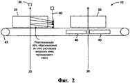
На фиг.2 представлено расположение тонкой гибкой перегородки, ослабляющей рентгеновское излучение в системе получения изображений в проходящем и рассеянном свете, в соответствии с вариантами исполнения настоящего изобретения.Figure 2 presents the location of a thin flexible partition that attenuates x-ray radiation in the system for obtaining images in transmitted and scattered light, in accordance with the variants of execution of the present invention.
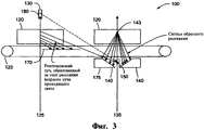
На фиг.3 схематически представлен еще один вариант исполнения системы получения изображений в проходящем и рассеянном свете, которая использует коллимирующие пластинки и регистрирующую фильтрацию.Figure 3 schematically shows another embodiment of a system for acquiring images in transmitted and scattered light, which uses collimating plates and recording filtering.
Осуществление изобретенияThe implementation of the invention
Способы и системы, позволяющие преодолеть взаимные влияния, которые имеют место при одновременном формировании изображений в проходящем и рассеянном свете представлены ниже вариантами исполнения настоящего изобретения. Кроме того, указанные способы и системы включают в себя программную обработку изображений, которая при отображении их оператору производит сопоставление значений формата изображения для изображений, полученных в проходящем и рассеянном свете, несмотря на то, что эти изображения формируются различными источниками и при различных положениях обследуемого объекта.Methods and systems to overcome the mutual influences that occur during the simultaneous formation of images in transmitted and scattered light are presented below options for the execution of the present invention. In addition, these methods and systems include software image processing, which, when displayed to the operator, compares the image format values for images obtained in transmitted and scattered light, despite the fact that these images are generated by different sources and at different positions of the object being examined .
Варианты исполнения настоящего изобретения описаны здесь в терминах рентгеновского излучения, тем не менее, очевидно, что эти методики и объем притязаний заявленного изобретения распространяются также на проникающее излучение любого вида, включая гамма излучение и т.п.Embodiments of the present invention are described herein in terms of x-ray radiation, however, it is obvious that these techniques and the scope of the claimed invention also apply to penetrating radiation of any kind, including gamma radiation and the like.
Объединение рентгеновской системы получения изображений в проходящем свете, использующей веерный луч и сегментную матрицу датчиков регистрации, с системой получения изображений в отраженном свете, которая использует сканирующий острый луч, позволяет получить мощную систему формирования изображений, сочетающую в себе лучшие стороны обеих технологий. Изображения, получаемые в проходящем свете, имеют высокую разрешающую способность, которая определяется размерами отдельных элементов матрицы датчиков регистрации. При использовании двуэнергетического источника рентгеновского излучения или двуэнергетической матрицы датчиков регистрации метод получения изображений в проходящем свете позволяет также воспроизводить эффективное атомное число Z отображаемых объектов. Разрешающая способность изображения, полученная с использованием обратного рассеяния, определяется шириной острого луча, который используется для сканирования объекта: чем уже луч, тем выше разрешающая способность. Однако при уменьшении ширины луча сокращается количество рентгеновских лучей в сканирующем пучке и, следовательно, снижается доступная статистика фотонов и возрастает наблюдаемая зернистость изображения, полученного обратным рассеянием. Таким образом, размер луча должен выбираться на основе компромисса между качеством изображения и разрешающей способностью.The combination of an X-ray system for obtaining images in transmitted light using a fan beam and a segmented matrix of registration sensors with a system for obtaining images in reflected light, which uses a scanning sharp beam, makes it possible to obtain a powerful imaging system that combines the best aspects of both technologies. Images obtained in transmitted light have a high resolution, which is determined by the size of the individual elements of the matrix of registration sensors. When using a dual-energy source of x-ray radiation or a dual-energy matrix of registration sensors, the method of obtaining images in transmitted light also allows reproducing the effective atomic number Z of the displayed objects. The resolution of the image obtained using backscattering is determined by the width of the sharp beam that is used to scan the object: the narrower the beam, the higher the resolution. However, as the beam width decreases, the number of X-rays in the scanning beam decreases and, therefore, the available photon statistics decreases and the observed graininess of the image obtained by backscattering increases. Thus, the beam size should be selected based on a trade-off between image quality and resolution.
Ниже со ссылками на фиг.1 описывается компактная система 10 для получения изображений, которая содержит отдельные подсистемы формирования изображений в проходящем свете и с использованием обратного рассеяния. Подлежащий осмотру объект 20, например багаж или сумка, сначала проходит по транспортерной ленте 23 через веерный луч 25, в результате чего формируется изображение в проходящем свете путем измерения интенсивности прошедшего через объект рентгеновского излучения при помощи регистрирующих элементов сегментной матрицы 30. Продвигаясь на транспортерной ленте по контрольному тоннелю объект затем проходит через острый луч 35 растрового сканирования подсистемы формирования изображений путем обратного рассеивания. Изображения в лучах обратного рассеяния формируются путем измерения интенсивности комптоновского рассеянного излучения, регистрируемого датчиками 40 рассеянного излучения, расположенных под транспортером 23 либо на стенах или потолке контрольного тоннеля.Below with reference to figure 1 describes a
Уменьшение взаимного влияния между подсистемами формирования изображенийReducing the mutual influence between the imaging subsystems
Основная техническая проблема, возникающая при объединении подсистем, использующих проходящий и рассеянный свет, в одну компактную систему формирования изображений, заключается в необходимости снижения взаимного влияния рентгеновского излучения в этих двух подсистемах. Исходя из практических соображений, связанных с пропускной способностью и стоимостью, предпочтительно, чтобы веерный луч проходящего света и острый луч подсистемы обратного рассеяния активизировались одновременно. Это означает, что рентгеновское излучение веерного луча 25, рассеянное от объекта 20 (или от любой поверхности самой системы для осмотра), регистрируется датчиками 40, предназначенными для регистрации обратного рассеяния. Аналогично, рентгеновские лучи, рассеянные объектом 20 при попадании на него острого луча 35, регистрируются матрицей 30 датчиков регистрации подсистемы формирования изображений в проходящем свете. Поскольку датчики регистрации обратного рассеяния имеют большие размеры по сравнению с регистрационными элементами подсистемы формирования изображений в проходящем свете, а также по причине того, что последняя использует веерный, а не острый луч, проблема взаимного влияния (или потерь) носит почти полностью однонаправленный характер, т.е. излучение рассеивается из веерного луча подсистемы формирования изображений в проходящем свете на датчиков регистрации обратного рассеяния. Это взаимное влияние проявляется на изображении, полученном при помощи обратного рассеяния, в виде более ярких нерезких областей, или, при большем своем проявлении, в виде вертикальной полосатости.The main technical problem that arises when combining subsystems using transmitted and scattered light into one compact imaging system is the need to reduce the mutual influence of x-rays in these two subsystems. Based on practical considerations related to bandwidth and cost, it is preferable that the fan beam of transmitted light and the sharp beam of the backscatter subsystem be activated simultaneously. This means that the x-ray radiation of the
В настоящем изобретении установлено, что уменьшение взаимного влияния рентгеновских лучей может быть достигнуто путем введения в аппаратные средства данной системы коллимирующих пластинок, обеспечения высокой точности при проектировании и размещении датчиков регистрации обратного рассеяния, а также за счет установки тонких перегородок для рентгеновского излучения между подсистемами формирования изображений в проходящем и в обратном рассеянном свете.The present invention has found that reducing the mutual influence of X-rays can be achieved by introducing collimating plates into the hardware of this system, ensuring high accuracy in the design and placement of backscatter detection sensors, and also by installing thin X-ray baffles between the imaging subsystems in transmitted and backscattered light.
Примеры коллимирующих пластинок 50 представлены на фиг.1. Эти пластинки выполнены таким образом, что область обзора датчиков регистрации обратного рассеяния ограничено регистрацией обратного рассеяния, исходящего от плоскости, которая содержит острый луч подсистемы формирования изображений с использованием обратного рассеяния. Рентгеновские лучи, которые рассеиваются из веерного луча подсистемы формирования изображений в проходящем свете, не могут проникнуть через эти коллиматоры и, следовательно, не будут оказывать отрицательного воздействия на сигнал обратного рассеяния. С наклонными коллимирующими пластинками, расположенными справа на датчика 40 обратного рассеяния, показанном на фиг.1, связана проблема, состоящая в том, что эти пластинки будут также ослаблять реальный сигнал обратного рассеяния, поступающий от сканирующего острого луча 35. Так, для правого датчика регистрации обратного рассеяния используется одна коллимирующая пластинка, параллельная острому лучу 35. Тем не менее, рентгеновские лучи, рассеянные от веерного луча проходящего света, могут попадать в датчик регистрации, ухудшая качество изображения, получаемого на основе обратного рассеяния.Examples of collimating plates 50 are shown in FIG. These plates are designed in such a way that the field of view of the backscatter detection sensors is limited to recording backscatter coming from a plane that contains a sharp beam from the backscatter imaging subsystem. X-rays that are scattered from the fan beam of the imaging subsystem in transmitted light cannot penetrate these collimators and, therefore, will not adversely affect the backscatter signal. The oblique collimating plates located to the right of the
Второй способ, обеспечивающий дальнейшее снижение нежелательных "взаимных влияний" между рентгеновскими лучами подсистем формирования изображений, состоит в размещении между этими двумя подсистемами ослабляющей излучение гибкой перегородки в виде свинцового отражателя 60, как это показано в качестве примера на фиг.2. Эта перегородка (или перегородки) может также состоять из вращающихся дверец, подпружиненных для возврата в исходное состояние. В данном варианте исполнения рассеянные рентгеновские лучи, рассеянные из веерного луча проходящего света, блокируются перегородкой до того, как они смогут попасть на датчики регистрации обратного рассеяния. Желательно, чтобы длина отражателя (или другой перегородки) была такой, чтобы отражатель не мог быть втянут или вдвинут объектом 20 в плоскость, содержащую острый или веерный луч. Установлено, что применение подобной перегородки позволяет уменьшить воздействие рентгеновских лучей проходящего света, рассеянных в сторону датчиков регистрации обратного рассеяния.The second method, which further reduces unwanted "mutual influences" between the X-rays of the imaging subsystems, consists in placing a radiation-damaging flexible partition in the form of a
Вычитание взаимного влиянияSubtraction of mutual influence
В добавление к описанным выше способам снижения взаимного влияния рентгеновских лучей индуцированный сигнал в датчиках регистрации обратного рассеяния за счет остаточного влияния системы формирования изображений в проходящем свете может быть вычтен и удален из сигнала обратного рассеяния. Это осуществляется путем измерения сигнала, поступающего от датчиков регистрации обратного рассеяния в момент кратковременного отключения острого луча подсистемы, использующей обратное рассеяние. Например, сканирующий острый луч может быть создан при помощи вращающегося отсекателя в виде диска с отверстиями. Поскольку каждое отверстие освещается рентгеновской трубкой, то при вращении дискового отсекателя острый рентгеновский луч проходит через отверстие, проходя по контрольному тоннелю. В течение короткого интервала времени, с момента, когда освещенная область только что покинула одно отверстие, и до того, когда другое отверстие войдет в эту освещенную область, острый луч по существу выключен. В течение этого короткого промежутка "отключенного луча" сигнал, поступающий от датчиков регистрации обратного рассеяния, главным образом, обусловлен взаимным влиянием веерного луча подсистемы формирования изображений в проходящем свете, который включен всегда. Этот сигнал используется для измерения мгновенной интенсивности потока веерного луча подсистемы формирования изображений в проходящем свете, рассеянного в датчики регистрации обратного излучения для данной строки изображения. Значение этой интенсивности может затем быть вычтено из соответствующей строки изображения, полученного в рассеянном свете для того, чтобы исключить сигнал взаимного влияния. Вычитание может быть произведено или в электронной схеме сбора информации, или позднее, во время обработки, перед представлением изображения оператору. Вычитание может быть выполнено при помощи процессора с сопряженной памятью, которая содержит команды, выполняемые процессором при выполнении операций, включающих вышеупомянутое вычитание. Как здесь, так и в формуле изобретения термин "память" включает, но не в качестве ограничения, твердотельные запоминающие устройства, средства на магнитных носителях, например жесткий диск, а также любые другие устройства, содержащие команды, которые могут выполняться процессором.In addition to the methods described above for reducing the mutual influence of X-rays, the induced signal in the backscatter detection sensors due to the residual effect of the transmitted image forming system can be subtracted and removed from the backscattered signal. This is done by measuring the signal from the backscatter registration sensors at the moment of a short-term shutdown of the sharp beam of the subsystem using backscattering. For example, a scanning sharp beam can be created using a rotating cutter in the form of a disk with holes. Since each hole is illuminated by an X-ray tube, a sharp X-ray beam passes through the hole during the rotation of the disk cutter and passes through the control tunnel. For a short period of time, from the moment when the illuminated area has just left one hole, and until the other hole enters this illuminated area, the sharp beam is essentially turned off. During this short period of the “disabled beam”, the signal from the backscatter detection sensors is mainly due to the mutual influence of the fan beam of the imaging subsystem in transmitted light, which is always on. This signal is used to measure the instantaneous intensity of the flow of the fan beam of the transmitted light imaging subsystem scattered into the feedback sensors for a given image line. The value of this intensity can then be subtracted from the corresponding line of the image obtained in scattered light in order to exclude the signal of mutual influence. Subtraction can be performed either in the electronic information collection circuit, or later, during processing, before the image is presented to the operator. Subtraction can be performed using a processor with conjugate memory, which contains instructions executed by the processor when performing operations involving the above subtraction. As here, and in the claims, the term "memory" includes, but is not limited to, solid state storage devices, magnetic media, such as a hard disk, as well as any other devices containing instructions that can be executed by the processor.
В других вариантах исполнения настоящего изобретения взаимное влияние подсистем формирования изображений в проходящем свете и подсистем формирования изображений с помощью обратного рассеяния уменьшается за счет применения коллимирующих пластинок, защитных экранов, а также предпочтительной ориентации датчиков регистрации рассеянного излучения, как это показано в системе 100, представленной на фиг.3. Далее указаны следующие усовершенствования по отношению к системе, представленной на фиг.1.:In other embodiments of the present invention, the mutual influence of transmission imaging subsystems and backscattering image forming subsystems is reduced by the use of collimating plates, protective shields, and the preferred orientation of the scattered radiation detection sensors, as shown in
(а) Активная поверхность датчиков 140 регистрации обратного рассеяния может быть наклонена по отношению к точке 143, из которой излучается сигнал обратного рассеяния. Такая конфигурация повышает вероятность регистрации сигнала обратного рассеяния от луча 135 обратного рассеяния и при этом минимизирует регистрацию взаимного влияния вследствие луча в проходящем свете. Подобная конфигурация также исключает необходимость установки коллимирующих пластинок на левостороннем детекторе. Для снижения регистрации паразитного рентгеновского излучения все остальные поверхности 175 детекторов обратного рассеяния могут быть ограждены экранирующим материалом, например свинцом.(a) The active surface of the
(б) Одиночная вертикальная пластинка 150 защищает активную поверхность правостороннего датчика регистрации обратного рассеяния от регистрации рассеянного излучения от луча 125 в проходящем свете.(b) A single
(в) Свинцовый экран 170, расположенный под транспортерной лентой 123 вблизи луча в проходящем свете, защищает левосторонний датчик 140 обратного рассеяния от воздействия рассеянного излучения от луча подсистемы формирования изображений в проходящем свете.(c) A
(г) Коллиматоры 180, расположенные перед детекторами проходящего света, предотвращают попадание на датчики 140 обратного рассеяния излучения, рассеянного из луча проникающего излучения от передней поверхности датчиков 130 регистрации проходящего света.(d)
Поскольку получение изображений в проходящем свете и при обратном рассеянии обеспечивается двумя различными способами, в общем случае эти изображения будут иметь разный формат. Таким образом, изображения одного и того же объекта, полученные этими двумя способами, могут иметь различную форму и размеры. Для того чтобы это не создавало неудобства оператору, настоящее изобретение включает в себя программный способ корректировки формата изображения, полученного в проходящем свете или в при обратном рассеянии (или в обоих случаях) таким образом, чтобы представляемые оператору изображения имели одинаковые размеры и форму. Обычно ширина объекта (в направлении движения транспортерной ленты) примерно одинаковая в изображениях в проходящем свете и при обратном рассеянии. Что же касается высоты объекта (в направлении, перпендикуляром движению транспортерной ленты), то она зачастую отличается у этих двух подсистем. Для того чтобы скорректировать это и обеспечить одинаковую высоту объекта для обоих изображений, к одному из них может быть применен известный коэффициент масштабирования. Кроме того, может быть использован программный алгоритм, определяющий высоту объекта в каждом изображении, и оба изображения могут быть промасштабированы соответствующим образом.Since obtaining images in transmitted light and backscattering is provided in two different ways, in the general case these images will have a different format. Thus, images of the same object obtained by these two methods can have different shapes and sizes. In order to avoid inconvenience to the operator, the present invention includes a software method for adjusting the image format obtained in transmitted light or in backscatter (or both) so that the images presented to the operator have the same size and shape. Usually the width of the object (in the direction of movement of the conveyor belt) is approximately the same in images in transmitted light and during backscattering. As for the height of the object (in the direction perpendicular to the movement of the conveyor belt), it often differs in these two subsystems. In order to correct this and ensure the same object height for both images, a known scaling factor can be applied to one of them. In addition, a software algorithm that determines the height of the object in each image can be used, and both images can be scaled accordingly.
Все рассмотренные выше варианты исполнения настоящего изобретения следует рассматривать только в качестве примеров, для специалистов в данной области техники очевидна возможность различных вариантов и модификаций. Например, несмотря на то что выше была описана система - с обратным рассеянием в различных вариантах исполнения изобретения, могут применяться другие виды получения изображения с использованием рассеяния света. В качестве еще одного примера можно привести систему, содержащую только один источник рентгеновского излучения, с помощью которого формируются как сканирующий острый луч, так и веерный луч проходящего света. Все варианты и модификации не выходят за рамки объема настоящего изобретения, который определен приведенной ниже формулой изобретения.All of the above embodiments of the present invention should be considered only as examples, for specialists in this field of technology, the obvious possibility of various options and modifications. For example, although the backscattering system in various embodiments of the invention has been described above, other types of image acquisition using light scattering may be used. As another example, we can cite a system containing only one source of x-ray radiation, with the help of which both a sharp scanning beam and a fan beam of transmitted light are formed. All variations and modifications are not beyond the scope of the present invention, which is defined by the following claims.
Claims (27)
а. облучение объекта первым лучом проникающего излучения,
b. генерирование сигнала пропускания на основе проникающего излучения, пропущенного через объект и зарегистрированного датчиком регистрации пропускания,
с. сканирование объекта вторым лучом проникающего излучения,
d. генерирование сигнала рассеивания на основе проникающего излучения, рассеянного объектом и зарегистрированного датчиком регистрации рассеивания,
е. корректирование любой помехи в сигнале рассеивания, возникающей вследствие первого луча проникающего излучения при наличии объекта, и
f. отображение изображения, видимого оператору и включающего информацию по меньшей мере от сигнала рассеивания.1. A method of inspecting an object, including
but. irradiating the object with the first ray of penetrating radiation,
b. generating a transmission signal based on penetrating radiation transmitted through the object and detected by the transmission detection sensor,
from. scanning an object with a second beam of penetrating radiation,
d. generating a scattering signal based on the penetrating radiation scattered by the object and detected by the scattering registration sensor,
e. the correction of any interference in the scattering signal resulting from the first beam of penetrating radiation in the presence of an object, and
f. displaying an image visible to the operator and including information from at least the scattering signal.
уменьшение проникающего излучения от первого луча, достигающего датчика регистрации рассеивания.5. The method according to claim 1, further comprising
reduction of penetrating radiation from the first beam reaching the scattering registration sensor.
а. первый источник излучения, испускающий первый луч проникающего излучения,
b. датчик регистрации пропускания для измерения интенсивности проникающего излучения, пропускаемого через объект первым лучом, и генерирования сигнала пропускания,
с. второй источник излучения, испускающий сканирующий луч проникающего излучения,
d. датчик регистрации рассеивания для регистрации проникающего излучения, рассеянного из сканирующего луча объектом, и генерирования сигнала рассеивания,
е. перегородку, уменьшающую излучение от первого источника излучения, которое достигает датчика регистрации рассеивания, и
f. процессор, запоминающее устройство и дисплей, причем запоминающее устройство содержит команды, заставляющие процессор корректировать любые помехи в сигнале рассеивания, возникающие вследствие первого луча проникающего излучения при наличии объекта, и отображать на дисплее видимое для оператора изображение, включающее информацию по меньшей мере от одного из следующих сигналов: сигнал рассеивания и сигнал пропускания.13. A system for inspecting an object, comprising
but. a first radiation source emitting a first beam of penetrating radiation,
b. a transmission detection sensor for measuring the intensity of the penetrating radiation transmitted through the object by the first beam and generating a transmission signal,
from. a second radiation source emitting a scanning beam of penetrating radiation,
d. a scattering registration sensor for detecting penetrating radiation scattered from the scanning beam by the object and generating a scattering signal,
e. a baffle reducing radiation from the first radiation source that reaches the scattering registration sensor, and
f. a processor, a storage device and a display, the storage device containing instructions causing the processor to correct any interference in the scattering signal resulting from the first beam of penetrating radiation in the presence of an object, and display on the display a visible image for the operator including information from at least one of the following Signals: scatter signal and pass signal.
а. источник излучения, испускающий первый луч проникающего излучения и сканирующий луч проникающего излучения,
b. датчик регистрации пропускания для измерения интенсивности проникающего излучения, пропускаемого через объект первым лучом, и генерирования сигнала пропускания,
с. датчик регистрации рассеивания для регистрации проникающего излучения, рассеянного из сканирующего луча объектом, и генерирования сигнала рассеивания,
d. перегородку, уменьшающую излучение от источника излучения, которое достигает датчика регистрации рассеивания, и
е. процессор, запоминающее устройство и дисплей, причем запоминающее устройство содержит команды, заставляющие процессор корректировать любые помехи в сигнале рассеивания, возникающие вследствие первого луча проникающего излучения при наличии объекта, и отображать на дисплее видимое для оператора изображение, включающее информацию по меньшей мере от одного из следующих сигналов: сигнал рассеивания и сигнал пропускания.21. A system for inspecting an object, comprising
but. a radiation source emitting a first beam of penetrating radiation and a scanning beam of penetrating radiation,
b. a transmission detection sensor for measuring the intensity of the penetrating radiation transmitted through the object by the first beam and generating a transmission signal,
from. a scattering registration sensor for detecting penetrating radiation scattered from the scanning beam by the object and generating a scattering signal,
d. a partition that reduces radiation from the radiation source, which reaches the scattering registration sensor, and
e. a processor, a storage device and a display, the storage device comprising instructions causing the processor to correct any noise in the scattering signal resulting from the first beam of penetrating radiation when an object is present and to display an image visible to the operator including information from at least one of the following signals: dispersion signal and transmission signal.
Applications Claiming Priority (2)
| Application Number | Priority Date | Filing Date | Title |
|---|---|---|---|
| US82216206P | 2006-08-11 | 2006-08-11 | |
| US60/822,162 | 2006-08-11 |
Related Parent Applications (1)
| Application Number | Title | Priority Date | Filing Date |
|---|---|---|---|
| RU2009108663/28A Division RU2448342C2 (en) | 2006-08-11 | 2007-08-07 | Object inspection system (versions) |
Publications (2)
| Publication Number | Publication Date |
|---|---|
| RU2011148960A RU2011148960A (en) | 2013-06-10 |
| RU2499251C2 true RU2499251C2 (en) | 2013-11-20 |
Family
ID=38920709
Family Applications (2)
| Application Number | Title | Priority Date | Filing Date |
|---|---|---|---|
| RU2011148960/28A RU2499251C2 (en) | 2006-08-11 | 2007-08-07 | X-ray inspection by simultaneous imaging based on transmission and back scattering of light |
| RU2009108663/28A RU2448342C2 (en) | 2006-08-11 | 2007-08-07 | Object inspection system (versions) |
Family Applications After (1)
| Application Number | Title | Priority Date | Filing Date |
|---|---|---|---|
| RU2009108663/28A RU2448342C2 (en) | 2006-08-11 | 2007-08-07 | Object inspection system (versions) |
Country Status (13)
| Country | Link |
|---|---|
| US (2) | US7555099B2 (en) |
| EP (1) | EP2049888B1 (en) |
| JP (2) | JP4688955B2 (en) |
| KR (2) | KR101263067B1 (en) |
| CN (1) | CN101501477B (en) |
| ES (1) | ES2474200T3 (en) |
| IL (2) | IL196967A (en) |
| MX (1) | MX2009001529A (en) |
| MY (2) | MY146301A (en) |
| PL (1) | PL2049888T3 (en) |
| RU (2) | RU2499251C2 (en) |
| SG (1) | SG165402A1 (en) |
| WO (1) | WO2008021807A2 (en) |
Families Citing this family (100)
| Publication number | Priority date | Publication date | Assignee | Title |
|---|---|---|---|---|
| US9958569B2 (en) | 2002-07-23 | 2018-05-01 | Rapiscan Systems, Inc. | Mobile imaging system and method for detection of contraband |
| US7963695B2 (en) | 2002-07-23 | 2011-06-21 | Rapiscan Systems, Inc. | Rotatable boom cargo scanning system |
| US8503605B2 (en) | 2002-07-23 | 2013-08-06 | Rapiscan Systems, Inc. | Four sided imaging system and method for detection of contraband |
| US8275091B2 (en) | 2002-07-23 | 2012-09-25 | Rapiscan Systems, Inc. | Compact mobile cargo scanning system |
| US8223919B2 (en) | 2003-04-25 | 2012-07-17 | Rapiscan Systems, Inc. | X-ray tomographic inspection systems for the identification of specific target items |
| GB0525593D0 (en) | 2005-12-16 | 2006-01-25 | Cxr Ltd | X-ray tomography inspection systems |
| US8243876B2 (en) | 2003-04-25 | 2012-08-14 | Rapiscan Systems, Inc. | X-ray scanners |
| US6928141B2 (en) | 2003-06-20 | 2005-08-09 | Rapiscan, Inc. | Relocatable X-ray imaging system and method for inspecting commercial vehicles and cargo containers |
| US7856081B2 (en) | 2003-09-15 | 2010-12-21 | Rapiscan Systems, Inc. | Methods and systems for rapid detection of concealed objects using fluorescence |
| US7471764B2 (en) | 2005-04-15 | 2008-12-30 | Rapiscan Security Products, Inc. | X-ray imaging system having improved weather resistance |
| US7526064B2 (en) | 2006-05-05 | 2009-04-28 | Rapiscan Security Products, Inc. | Multiple pass cargo inspection system |
| US7499523B2 (en) * | 2006-08-02 | 2009-03-03 | General Electric Company | Systems and methods for identifying a substance |
| RU2499251C2 (en) * | 2006-08-11 | 2013-11-20 | Эмерикэн Сайэнс Энд Энджиниэринг, Инк. | X-ray inspection by simultaneous imaging based on transmission and back scattering of light |
| US8552858B2 (en) * | 2007-02-27 | 2013-10-08 | Koninklijke Philips N.V. | Simulation and visualization of scattered radiation |
| US7742568B2 (en) | 2007-06-09 | 2010-06-22 | Spectrum San Diego, Inc. | Automobile scanning system |
| US8532259B2 (en) | 2008-04-17 | 2013-09-10 | University Of Florida Research Foundation, Inc. | Method and apparatus for computed imaging backscatter radiography |
| GB0809110D0 (en) | 2008-05-20 | 2008-06-25 | Rapiscan Security Products Inc | Gantry scanner systems |
| US8625738B2 (en) * | 2008-09-22 | 2014-01-07 | Telesecurity Sciences, Inc. | Radiation therapy and scanning system |
| US8530849B2 (en) * | 2008-09-22 | 2013-09-10 | Telesecurity Sciences, Inc. | Electron beam scanner |
| US7835495B2 (en) * | 2008-10-31 | 2010-11-16 | Morpho Detection, Inc. | System and method for X-ray diffraction imaging |
| EP2430396B1 (en) | 2009-05-16 | 2020-01-15 | Rapiscan Systems, Inc. | Systems and methods for automated, rapid detection of high-atomic-number materials |
| US9310323B2 (en) | 2009-05-16 | 2016-04-12 | Rapiscan Systems, Inc. | Systems and methods for high-Z threat alarm resolution |
| BR112012000884B8 (en) * | 2009-07-13 | 2021-06-22 | Rapiscan Systems Inc | sweeping system for inspecting cargo, method for inspecting a vehicle and sweeping system for inspecting a vehicle |
| US8314394B1 (en) | 2009-11-04 | 2012-11-20 | Science Applications International Corporation | System and method for three-dimensional imaging using scattering from annihilation coincidence photons |
| WO2011059545A2 (en) * | 2009-11-11 | 2011-05-19 | Physical Optics Corporation | X-ray imaging system and method |
| US8705694B2 (en) * | 2009-11-11 | 2014-04-22 | Physical Optics Corporation | X-ray imaging system and method |
| KR100956797B1 (en) * | 2009-11-19 | 2010-05-07 | (주)자비스 | X-ray inspection apparatus for board shaped pad |
| US10393915B2 (en) | 2010-02-25 | 2019-08-27 | Rapiscan Systems, Inc. | Integrated primary and special nuclear material alarm resolution |
| US8750454B2 (en) * | 2010-02-25 | 2014-06-10 | Rapiscan Systems, Inc. | High-energy X-ray-spectroscopy-based inspection system and methods to determine the atomic number of materials |
| US8766764B2 (en) | 2010-09-23 | 2014-07-01 | Rapiscan Systems, Inc. | Automated personnel screening system and method |
| US9055886B1 (en) | 2011-01-05 | 2015-06-16 | Sandia Corporation | Automatic tool alignment in a backscatter x-ray scanning system |
| ES2729705T3 (en) | 2011-01-07 | 2019-11-05 | Huron Valley Steel Corp | Scrap Sorting System |
| RU2550319C2 (en) * | 2011-02-08 | 2015-05-10 | Американ Сайенс Энд Инжиниринг, Инк. | Backscatter energy analysis for classification of materials based on positional non-commutativity |
| US8908831B2 (en) | 2011-02-08 | 2014-12-09 | Rapiscan Systems, Inc. | Covert surveillance using multi-modality sensing |
| PL2673660T3 (en) | 2011-02-08 | 2018-01-31 | Rapiscan Systems Inc | Covert surveillance using multi-modality sensing |
| EP2697630A2 (en) * | 2011-04-15 | 2014-02-19 | American Science & Engineering, Inc. | Methods to perform backscatter inspection of complex targets in confined spaces |
| CN102183533B (en) * | 2011-05-24 | 2013-04-24 | 深圳市鑫源通电子有限公司 | Channel type X-ray safety check method and device |
| US9224573B2 (en) | 2011-06-09 | 2015-12-29 | Rapiscan Systems, Inc. | System and method for X-ray source weight reduction |
| US9218933B2 (en) | 2011-06-09 | 2015-12-22 | Rapidscan Systems, Inc. | Low-dose radiographic imaging system |
| KR102067367B1 (en) | 2011-09-07 | 2020-02-11 | 라피스캔 시스템스, 인코포레이티드 | X-ray inspection method that integrates manifest data with imaging/detection processing |
| IN2014CN03172A (en) * | 2011-11-04 | 2015-07-03 | Imec | |
| EP2776799B1 (en) * | 2011-11-04 | 2019-05-22 | IMEC vzw | Spectral camera with mirrors for projecting multiple adjacent image copies onto sensor array |
| EP2810296A4 (en) | 2012-02-03 | 2015-12-30 | Rapiscan Systems Inc | Combined scatter and transmission multi-view imaging system |
| CA2864354C (en) | 2012-02-14 | 2023-02-28 | American Science And Engineering, Inc. | X-ray inspection using wavelength-shifting fiber-coupled scintillation detectors |
| US10670740B2 (en) | 2012-02-14 | 2020-06-02 | American Science And Engineering, Inc. | Spectral discrimination using wavelength-shifting fiber-coupled scintillation detectors |
| US9709514B2 (en) * | 2012-04-02 | 2017-07-18 | The Boeing Company | X-ray backscatter system and method for detecting discrepancies in items |
| CN102707324B (en) * | 2012-05-21 | 2015-01-21 | 貊梁 | Backscatter and transmission combined safety detector of X rays |
| KR101378757B1 (en) * | 2012-08-30 | 2014-03-27 | 한국원자력연구원 | Radiation imaging equipment and method available to obtain element date of material and select dimensions of image |
| US8983234B2 (en) | 2012-09-28 | 2015-03-17 | Varian Medical Systems, Inc. | Method and apparatus pertaining to using imaging information to identify a spectrum |
| FR3000211B1 (en) | 2012-12-20 | 2015-12-11 | Commissariat Energie Atomique | SCANNING LIGHTING DEVICE, IMAGING DEVICE COMPRISING SAME, AND METHOD FOR OPERATING SAME |
| WO2014107675A2 (en) | 2013-01-07 | 2014-07-10 | Rapiscan Systems, Inc. | X-ray scanner with partial energy discriminating detector array |
| PL2952068T3 (en) | 2013-01-31 | 2021-07-26 | Rapiscan Systems, Inc. | Portable security inspection system |
| MX351925B (en) * | 2013-05-09 | 2017-11-03 | Rapiscan Systems Inc | Integrated primary and special nuclear material alarm resolution. |
| WO2015013359A1 (en) | 2013-07-23 | 2015-01-29 | Rapiscan Systems, Inc. | Methods for improving processing speed for object inspection |
| CN105612416B (en) * | 2013-07-25 | 2019-01-01 | 模拟技术公司 | The generation of the diffractive features of article in object |
| CN103728324B (en) * | 2013-12-18 | 2016-08-17 | 中国原子能科学研究院 | A kind of nuclear fuel assembly nondestructive detection device for high-energy X-ray |
| CN104374783B (en) * | 2013-12-26 | 2017-06-16 | 清华大学 | CT system and its method |
| US9557427B2 (en) | 2014-01-08 | 2017-01-31 | Rapiscan Systems, Inc. | Thin gap chamber neutron detectors |
| US11280898B2 (en) | 2014-03-07 | 2022-03-22 | Rapiscan Systems, Inc. | Radar-based baggage and parcel inspection systems |
| US9851312B2 (en) * | 2014-05-07 | 2017-12-26 | The Boeing Company | Backscatter inspection systems, and related methods |
| US9867271B2 (en) | 2014-05-16 | 2018-01-09 | American Science And Engineering, Inc. | Source for intra-pulse multi-energy X-ray cargo inspection |
| US11266006B2 (en) | 2014-05-16 | 2022-03-01 | American Science And Engineering, Inc. | Method and system for timing the injections of electron beams in a multi-energy x-ray cargo inspection system |
| US10228487B2 (en) | 2014-06-30 | 2019-03-12 | American Science And Engineering, Inc. | Rapidly relocatable modular cargo container scanner |
| MY191339A (en) | 2014-08-19 | 2022-06-16 | Nuctech Co Ltd | Apparatus and method for inspecting moving target |
| CN105445808B (en) * | 2014-08-19 | 2018-10-02 | 清华大学 | The device and method that mobile target is checked |
| CN105374654B (en) | 2014-08-25 | 2018-11-06 | 同方威视技术股份有限公司 | Electron source, x-ray source, the equipment for having used the x-ray source |
| CN105445290A (en) | 2014-09-02 | 2016-03-30 | 同方威视技术股份有限公司 | Product quality online detection X-ray apparatus |
| CN105372269B (en) * | 2014-09-02 | 2019-01-15 | 同方威视技术股份有限公司 | X-ray product quality automatic detection device |
| WO2016081881A1 (en) | 2014-11-20 | 2016-05-26 | Heuresis Corporation | X-ray scanning system |
| BR112017011068A2 (en) | 2014-11-25 | 2018-07-10 | Rapiscan Systems, Inc. | smart security management system |
| CN104535594A (en) * | 2015-01-08 | 2015-04-22 | 安徽中福光电科技有限公司 | Luggage security check method based on X-rays, DR and CBS and intelligent X-ray machine |
| US9739727B2 (en) * | 2015-01-21 | 2017-08-22 | The Boeing Company | Systems and methods for aligning an aperture |
| JP6746603B2 (en) | 2015-03-20 | 2020-08-26 | ラピスカン システムズ、インコーポレイテッド | Handheld portable backscatter inspection system |
| US11536672B2 (en) | 2015-09-08 | 2022-12-27 | American Science And Engineering, Inc. | Systems and methods for using backscatter imaging in precision agriculture |
| PL3347707T3 (en) | 2015-09-08 | 2022-11-21 | American Science & Engineering, Inc. | Backscatter imaging for precision agriculture |
| JP6746691B2 (en) | 2015-09-10 | 2020-08-26 | アメリカン サイエンス アンド エンジニアリング, インコーポレイテッドAmerican Science and Engineering, Inc. | Backscattering characteristics evaluation using inter-line adaptive electromagnetic X-ray scanning |
| US10345479B2 (en) | 2015-09-16 | 2019-07-09 | Rapiscan Systems, Inc. | Portable X-ray scanner |
| EP3764281A1 (en) | 2016-02-22 | 2021-01-13 | Rapiscan Systems, Inc. | Methods of identifying firearms in radiographic images |
| US10185052B2 (en) | 2016-12-19 | 2019-01-22 | Baker Hughes, A Ge Company, Llc | Constrained backscatter gamma ray casing and cement inspection tool |
| US10600609B2 (en) | 2017-01-31 | 2020-03-24 | Rapiscan Systems, Inc. | High-power X-ray sources and methods of operation |
| US10770195B2 (en) * | 2017-04-05 | 2020-09-08 | Viken Detection Corporation | X-ray chopper wheel assembly |
| MX2019012365A (en) | 2017-04-17 | 2020-02-07 | Rapiscan Systems Inc | X-ray tomography inspection systems and methods. |
| CN107991327B (en) | 2018-01-05 | 2021-02-09 | 同方威视技术股份有限公司 | Security inspection system and method |
| JP6629372B2 (en) * | 2018-03-15 | 2020-01-15 | 日本信号株式会社 | Radiation inspection equipment and baggage inspection equipment |
| GB2590561B (en) | 2018-06-20 | 2021-12-08 | American Science & Eng Inc | Wavelength-shifting sheet-coupled scintillation detectors |
| CN110907481A (en) * | 2018-09-18 | 2020-03-24 | 同方威视技术股份有限公司 | X-ray detection system and detection method |
| CN109142404A (en) * | 2018-11-01 | 2019-01-04 | 同方威视技术股份有限公司 | Back scattering imaging system, scanography system and backscatter images imaging method |
| US11594001B2 (en) | 2020-01-20 | 2023-02-28 | Rapiscan Systems, Inc. | Methods and systems for generating three-dimensional images that enable improved visualization and interaction with objects in the three-dimensional images |
| US11212902B2 (en) | 2020-02-25 | 2021-12-28 | Rapiscan Systems, Inc. | Multiplexed drive systems and methods for a multi-emitter X-ray source |
| US11193898B1 (en) | 2020-06-01 | 2021-12-07 | American Science And Engineering, Inc. | Systems and methods for controlling image contrast in an X-ray system |
| WO2021247615A1 (en) | 2020-06-02 | 2021-12-09 | Viken Detection Corporation | X-ray imaging apparatus and method |
| US11175245B1 (en) | 2020-06-15 | 2021-11-16 | American Science And Engineering, Inc. | Scatter X-ray imaging with adaptive scanning beam intensity |
| US20230251209A1 (en) * | 2020-07-06 | 2023-08-10 | Smiths Detection Inc. | Systems and methods for inspection portals |
| CN113970567B (en) * | 2020-07-22 | 2023-01-31 | 同方威视技术股份有限公司 | Back scattering imaging device, control method and inspection system |
| US11340361B1 (en) | 2020-11-23 | 2022-05-24 | American Science And Engineering, Inc. | Wireless transmission detector panel for an X-ray scanner |
| CN117063064A (en) | 2021-02-23 | 2023-11-14 | 拉皮斯坎系统股份有限公司 | System and method for removing crosstalk signals in one or more scanning systems having multiple X-ray sources |
| KR20230092510A (en) * | 2021-12-17 | 2023-06-26 | 한국해양과학기술원 | Back Scattering Radiography Imaging System for Precise Searching of Container Hazardous Cargo and Method for Controlling the Same |
| CN114624785B (en) * | 2022-05-16 | 2022-08-19 | 天津速通科技有限公司 | Same light source setting method suitable for novel double-source mixed detection type channel type security inspection system |
| WO2024030046A1 (en) * | 2022-08-01 | 2024-02-08 | Obshhestvo S Ogranichennoj Otvetstvennost`Yu "Indikom" (Ooo "Indikom") | Method for determining the spatial profile of inspected objects |
| KR102657570B1 (en) | 2023-12-27 | 2024-04-15 | 한국해양과학기술원 | Cross-search system for simultaneous X-ray image acquisition and radioactive material detection |
Citations (6)
| Publication number | Priority date | Publication date | Assignee | Title |
|---|---|---|---|---|
| RU2119660C1 (en) * | 1997-04-08 | 1998-09-27 | Закрытое акционерное общество "Кванта Инвест" | Gear determining composition and structure of inhomogeneous object ( versions ) |
| US6151381A (en) * | 1998-01-28 | 2000-11-21 | American Science And Engineering, Inc. | Gated transmission and scatter detection for x-ray imaging |
| US6192104B1 (en) * | 1998-11-30 | 2001-02-20 | American Science And Engineering, Inc. | Fan and pencil beams from a common source for x-ray inspection |
| US6546072B1 (en) * | 1999-07-30 | 2003-04-08 | American Science And Engineering, Inc. | Transmission enhanced scatter imaging |
| WO2004043740A2 (en) * | 2002-11-06 | 2004-05-27 | American Science And Engineering, Inc. | X-ray backscatter mobile inspection van |
| RU2253861C2 (en) * | 1999-11-13 | 2005-06-10 | Хайманн Системс Гмбх | Method and device for detecting prohibited objects |
Family Cites Families (45)
| Publication number | Priority date | Publication date | Assignee | Title |
|---|---|---|---|---|
| DK131955C (en) | 1973-10-09 | 1976-02-23 | I Leunbach | PROCEDURE AND SYSTEM FOR DETERMINING THE ELECTRONITY OF A PART VOLUME OF A BODY |
| US4047029A (en) | 1976-07-02 | 1977-09-06 | Allport John J | Self-compensating X-ray or γ-ray thickness gauge |
| DE2939146A1 (en) | 1979-09-27 | 1981-04-16 | Philips Patentverwaltung Gmbh, 2000 Hamburg | METHOD FOR EXAMINING A BODY WITH Pervasive RADIATION |
| US4525854A (en) | 1983-03-22 | 1985-06-25 | Troxler Electronic Laboratories, Inc. | Radiation scatter apparatus and method |
| US4768214A (en) | 1985-01-16 | 1988-08-30 | American Science And Engineering, Inc. | Imaging |
| DE3764315D1 (en) | 1986-05-28 | 1990-09-20 | Heimann Gmbh | X-RAY SCANNER. |
| US4799247A (en) | 1986-06-20 | 1989-01-17 | American Science And Engineering, Inc. | X-ray imaging particularly adapted for low Z materials |
| US4864142A (en) | 1988-01-11 | 1989-09-05 | Penetron, Inc. | Method and apparatus for the noninvasive interrogation of objects |
| US5127030A (en) * | 1989-02-28 | 1992-06-30 | American Science And Engineering, Inc. | Tomographic imaging with improved collimator |
| US5016173A (en) * | 1989-04-13 | 1991-05-14 | Vanguard Imaging Ltd. | Apparatus and method for monitoring visually accessible surfaces of the body |
| EP0412190B1 (en) | 1989-08-09 | 1993-10-27 | Heimann Systems GmbH & Co. KG | Device for transmitting fan-shaped radiation through objects |
| JPH04364454A (en) * | 1991-06-11 | 1992-12-16 | Toshiba Corp | Scattered x-ray measuring apparatus |
| US5253283A (en) | 1991-12-23 | 1993-10-12 | American Science And Engineering, Inc. | Inspection method and apparatus with single color pixel imaging |
| US5430787A (en) | 1992-12-03 | 1995-07-04 | The United States Of America As Represented By The Secretary Of Commerce | Compton scattering tomography |
| US5692029A (en) | 1993-01-15 | 1997-11-25 | Technology International Incorporated | Detection of concealed explosives and contraband |
| DE4311174C2 (en) | 1993-04-05 | 1996-02-15 | Heimann Systems Gmbh & Co | X-ray inspection system for containers and trucks |
| US5428657A (en) | 1994-03-22 | 1995-06-27 | Georgia Tech Research Corporation | X-ray monitoring system |
| US5600700A (en) | 1995-09-25 | 1997-02-04 | Vivid Technologies, Inc. | Detecting explosives or other contraband by employing transmitted and scattered X-rays |
| US5642393A (en) | 1995-09-26 | 1997-06-24 | Vivid Technologies, Inc. | Detecting contraband by employing interactive multiprobe tomography |
| US5764683B1 (en) | 1996-02-12 | 2000-11-21 | American Science & Eng Inc | Mobile x-ray inspection system for large objects |
| US5638420A (en) | 1996-07-03 | 1997-06-10 | Advanced Research And Applications Corporation | Straddle inspection system |
| AU3888497A (en) | 1996-07-22 | 1998-02-10 | American Science And Engineering Inc. | System for rapid x-ray inspection of enclosures |
| US5763886A (en) | 1996-08-07 | 1998-06-09 | Northrop Grumman Corporation | Two-dimensional imaging backscatter probe |
| US5974111A (en) | 1996-09-24 | 1999-10-26 | Vivid Technologies, Inc. | Identifying explosives or other contraband by employing transmitted or scattered X-rays |
| US5940468A (en) | 1996-11-08 | 1999-08-17 | American Science And Engineering, Inc. | Coded aperture X-ray imaging system |
| JP3878259B2 (en) * | 1996-11-13 | 2007-02-07 | 東芝医用システムエンジニアリング株式会社 | Medical image processing device |
| US5912460A (en) | 1997-03-06 | 1999-06-15 | Schlumberger Technology Corporation | Method for determining formation density and formation photo-electric factor with a multi-detector-gamma-ray tool |
| US5917880A (en) | 1997-05-29 | 1999-06-29 | Eg&G Astrophysics | X-ray inspection apparatus |
| US6320933B1 (en) | 1998-11-30 | 2001-11-20 | American Science And Engineering, Inc. | Multiple scatter system for threat identification |
| US6421420B1 (en) | 1998-12-01 | 2002-07-16 | American Science & Engineering, Inc. | Method and apparatus for generating sequential beams of penetrating radiation |
| US6249567B1 (en) | 1998-12-01 | 2001-06-19 | American Science & Engineering, Inc. | X-ray back scatter imaging system for undercarriage inspection |
| US6282260B1 (en) | 1998-12-14 | 2001-08-28 | American Science & Engineering, Inc. | Unilateral hand-held x-ray inspection apparatus |
| US6459764B1 (en) | 1999-01-27 | 2002-10-01 | American Science And Engineering, Inc. | Drive-through vehicle inspection system |
| US6687326B1 (en) | 2001-04-11 | 2004-02-03 | Analogic Corporation | Method of and system for correcting scatter in a computed tomography scanner |
| US7072440B2 (en) | 2001-10-19 | 2006-07-04 | Control Screening, Llc | Tomographic scanning X-ray inspection system using transmitted and Compton scattered radiation |
| US6661867B2 (en) | 2001-10-19 | 2003-12-09 | Control Screening, Llc | Tomographic scanning X-ray inspection system using transmitted and compton scattered radiation |
| US6872001B1 (en) * | 2003-05-05 | 2005-03-29 | Peco Controls Corp. | X-ray shielding structure for food inspection station |
| US7092485B2 (en) | 2003-05-27 | 2006-08-15 | Control Screening, Llc | X-ray inspection system for detecting explosives and other contraband |
| SE0301937D0 (en) * | 2003-07-01 | 2003-07-01 | Blue Air Ab | water Filters |
| RU2256169C1 (en) * | 2004-02-13 | 2005-07-10 | Общестов с ограниченной ответственностью "Институт рентгеновской оптики" | Method and device for investigating object in dissipated and/or passed radiation |
| US20050185757A1 (en) * | 2004-02-20 | 2005-08-25 | Kresse David E. | Apparatus and method for nonintrusively inspecting an object |
| DK1733213T3 (en) * | 2004-04-09 | 2010-05-03 | American Science & Eng Inc | Eliminating cross-talk in a multi-source retransmission inspection portal by ensuring that only one source emits radiation at a time |
| US7092481B2 (en) * | 2004-05-19 | 2006-08-15 | General Electric Company | Direct conversion energy discriminating CT detector |
| US7190757B2 (en) * | 2004-05-21 | 2007-03-13 | Analogic Corporation | Method of and system for computing effective atomic number images in multi-energy computed tomography |
| RU2499251C2 (en) * | 2006-08-11 | 2013-11-20 | Эмерикэн Сайэнс Энд Энджиниэринг, Инк. | X-ray inspection by simultaneous imaging based on transmission and back scattering of light |
-
2007
- 2007-08-07 RU RU2011148960/28A patent/RU2499251C2/en active
- 2007-08-07 MX MX2009001529A patent/MX2009001529A/en active IP Right Grant
- 2007-08-07 RU RU2009108663/28A patent/RU2448342C2/en active
- 2007-08-07 SG SG201006815-3A patent/SG165402A1/en unknown
- 2007-08-07 US US11/834,888 patent/US7555099B2/en active Active
- 2007-08-07 ES ES07840728.5T patent/ES2474200T3/en active Active
- 2007-08-07 KR KR1020107004752A patent/KR101263067B1/en active IP Right Grant
- 2007-08-07 EP EP07840728.5A patent/EP2049888B1/en active Active
- 2007-08-07 CN CN200780029927.6A patent/CN101501477B/en active Active
- 2007-08-07 MY MYPI2010001073A patent/MY146301A/en unknown
- 2007-08-07 WO PCT/US2007/075323 patent/WO2008021807A2/en active Application Filing
- 2007-08-07 JP JP2009523942A patent/JP4688955B2/en not_active Expired - Fee Related
- 2007-08-07 PL PL07840728T patent/PL2049888T3/en unknown
- 2007-08-07 KR KR1020097002704A patent/KR101034753B1/en active IP Right Grant
- 2007-08-07 MY MYPI20090212A patent/MY142674A/en unknown
-
2009
- 2009-02-09 IL IL196967A patent/IL196967A/en active IP Right Grant
- 2009-06-22 US US12/488,635 patent/US7995707B2/en active Active
-
2010
- 2010-05-28 JP JP2010123342A patent/JP5303508B2/en not_active Expired - Fee Related
-
2012
- 2012-09-11 IL IL221892A patent/IL221892A/en active IP Right Grant
Patent Citations (6)
| Publication number | Priority date | Publication date | Assignee | Title |
|---|---|---|---|---|
| RU2119660C1 (en) * | 1997-04-08 | 1998-09-27 | Закрытое акционерное общество "Кванта Инвест" | Gear determining composition and structure of inhomogeneous object ( versions ) |
| US6151381A (en) * | 1998-01-28 | 2000-11-21 | American Science And Engineering, Inc. | Gated transmission and scatter detection for x-ray imaging |
| US6192104B1 (en) * | 1998-11-30 | 2001-02-20 | American Science And Engineering, Inc. | Fan and pencil beams from a common source for x-ray inspection |
| US6546072B1 (en) * | 1999-07-30 | 2003-04-08 | American Science And Engineering, Inc. | Transmission enhanced scatter imaging |
| RU2253861C2 (en) * | 1999-11-13 | 2005-06-10 | Хайманн Системс Гмбх | Method and device for detecting prohibited objects |
| WO2004043740A2 (en) * | 2002-11-06 | 2004-05-27 | American Science And Engineering, Inc. | X-ray backscatter mobile inspection van |
Also Published As
| Publication number | Publication date |
|---|---|
| SG165402A1 (en) | 2010-10-28 |
| CN101501477B (en) | 2014-07-02 |
| EP2049888A2 (en) | 2009-04-22 |
| JP2010500576A (en) | 2010-01-07 |
| KR20090046827A (en) | 2009-05-11 |
| ES2474200T3 (en) | 2014-07-08 |
| IL196967A0 (en) | 2009-11-18 |
| WO2008021807A2 (en) | 2008-02-21 |
| US7555099B2 (en) | 2009-06-30 |
| PL2049888T3 (en) | 2014-08-29 |
| US20090268871A1 (en) | 2009-10-29 |
| RU2448342C2 (en) | 2012-04-20 |
| WO2008021807A3 (en) | 2008-04-17 |
| KR101034753B1 (en) | 2011-05-17 |
| MY142674A (en) | 2010-12-15 |
| MY146301A (en) | 2012-07-31 |
| KR20100044242A (en) | 2010-04-29 |
| CN101501477A (en) | 2009-08-05 |
| JP2010181424A (en) | 2010-08-19 |
| MX2009001529A (en) | 2009-02-18 |
| RU2011148960A (en) | 2013-06-10 |
| KR101263067B1 (en) | 2013-05-09 |
| EP2049888B1 (en) | 2014-05-14 |
| JP5303508B2 (en) | 2013-10-02 |
| IL196967A (en) | 2012-10-31 |
| US7995707B2 (en) | 2011-08-09 |
| US20080037707A1 (en) | 2008-02-14 |
| JP4688955B2 (en) | 2011-05-25 |
| RU2009108663A (en) | 2010-09-20 |
| IL221892A (en) | 2015-04-30 |
Similar Documents
| Publication | Publication Date | Title |
|---|---|---|
| RU2499251C2 (en) | X-ray inspection by simultaneous imaging based on transmission and back scattering of light | |
| RU2444723C2 (en) | Apparatus and method of inspecting objects | |
| US7706502B2 (en) | Cargo container inspection system and apparatus | |
| US5181234A (en) | X-ray backscatter detection system | |
| US7408160B2 (en) | Density detection using real time discrete photon counting for fast moving targets | |
| US7702075B2 (en) | Energy spectrum modulation apparatus, material discrimination method and device, image processing method | |
| US20080298546A1 (en) | Cargo container inspection method | |
| US10386532B2 (en) | Radiation signal processing system | |
| US20080043913A1 (en) | Personnel X-ray Inspection System | |
| US8884236B2 (en) | Detector with active collimators | |
| US7388205B1 (en) | System and method for target inspection using discrete photon counting and neutron detection | |
| US20070030955A1 (en) | Scatter imaging system | |
| WO1992002937A1 (en) | X-ray backscatter detection system | |
| NL2009984C2 (en) | Method and device for screening objects for the presence of foreign substances. | |
| WO2008099334A2 (en) | Computed tomography inspection |