RU2498345C1 - Integrated automatic tracking system - Google Patents
Integrated automatic tracking system Download PDFInfo
- Publication number
- RU2498345C1 RU2498345C1 RU2012119000/07A RU2012119000A RU2498345C1 RU 2498345 C1 RU2498345 C1 RU 2498345C1 RU 2012119000/07 A RU2012119000/07 A RU 2012119000/07A RU 2012119000 A RU2012119000 A RU 2012119000A RU 2498345 C1 RU2498345 C1 RU 2498345C1
- Authority
- RU
- Russia
- Prior art keywords
- output
- input
- switch
- tracking
- inputs
- Prior art date
Links
Images


Landscapes
- Aiming, Guidance, Guns With A Light Source, Armor, Camouflage, And Targets (AREA)
Abstract
Description
Изобретение относится к автоматическому регулированию и предназначено для систем автоматического наблюдения и сопровождения за подвижными объектами в пространстве преимущественно с качающегося основания и может быть использовано для управления воздушным движением и уничтожения маневрирующих подвижных целей.The invention relates to automatic control and is intended for automatic monitoring and tracking systems for moving objects in space mainly from a swinging base and can be used to control air traffic and destroy maneuvering moving targets.
Известна телевизионно-оптическая система сопровождения со следящим стробом, содержащая телевизионную камеру, устройство обработки видеосигнала, решающее устройство, привод наведения. [1] (Барсуков Ф.И. Величкин А.И., Сухарев А.Д. Телевизионные системы летательных аппаратов. - М.: Советское радио, 1979. - 256 с., стр.232, рис.7.17, аналог).Known television-optical tracking system with a tracking strobe, containing a television camera, a video processing device, a deciding device, a guidance drive. [1] (Barsukov F.I. Velichkin A.I., Sukharev A.D. Television systems of aircraft. - M.: Soviet Radio, 1979. - 256 p., P. 232, fig. 7.17, analogue).
Недостатком данной телевизионной системы является недостаточная точность сопровождения целей с подвижного основания из-за отсутствия системы стабилизации оптической линии визирования и, как следствие, наличие динамической инерционности исполнительного привода и контура электронного слежения. Эта система неспособна к автоматическому захвату объекта на автосопровождение.The disadvantage of this television system is the lack of accuracy in tracking targets from a moving base due to the lack of a stabilization system for the optical line of sight and, as a result, the dynamic inertia of the actuator and the electronic tracking circuit. This system is not capable of automatically capturing an object for auto tracking.
Известна также телевизионно-оптическая система [2] (Грязин Г.Н., Оптико-электронные системы для обзора пространства: Системы телевидения. Л., Машиностроение, Ленинград. отд-ние. - 1988, стр.8, 9, рис.4, аналог), содержащая последовательно соединенные телевизионный датчик, устройство усиления и обработки сигнала, вычислительное устройство (в совокупности образующие пеленгатор) и исполнительный орган. Исполнительный орган, выполняющий функции блока наведения и стабилизации, кинематически связан с оптико-электронным (телевизионным) датчиком пеленгатора.Also known is the television-optical system [2] (Gryazin GN, Optoelectronic systems for space viewing: Television systems. L., Mechanical engineering, Leningrad. Department. - 1988, p. 8, 9, Fig. 4 , analogue), containing a television sensor in series, a signal amplification and processing device, a computing device (together forming a direction finder), and an actuator. The executive body, which performs the functions of the guidance and stabilization unit, is kinematically connected with the optoelectronic (television) direction finder sensor.
В известной системе переход в автоматический режим осуществляется посредством предварительного разворота пеленгатора на предназначенную для сопровождения цель таким образом, чтобы она оказалась в пределах окна захвата внутри поля зрения. Однако при увеличении угловых скоростей и ускорений визирования цели вероятность перехода в автоматический режим сопровождения падает. Это объясняется, с одной стороны, падением контраста изображения цели, перемещающейся относительно растра [2] (Грязин Г.Н., Оптико-электронные системы для обзора пространства: Системы телевидения. Л., Машиностроение, Ленинградское отделение. - 1988, стр.209-212). С другой стороны, если предварительный разворот пеленгатора осуществляется в полуавтоматическом режиме с участием человека оператора, увеличиваются ошибки сопровождения высокоскоростной цели оператором в силу ограниченности его динамических характеристик, приводящих к недопустимым переходным процессам в оптико-электронной системе, вызывающим срыв автосопровождения [3] (Цибулевский И.Е. Человек как звено следящей системы. - М., Наука, 1981. - 288 с.).In the known system, the transition to automatic mode is carried out by preliminary deploying the direction finder to the target intended for tracking so that it is within the capture window within the field of view. However, with increasing angular velocities and acceleration of target sighting, the probability of transition to the automatic tracking mode decreases. This is explained, on the one hand, by a decrease in the contrast of the image of a target moving relative to the raster [2] (Gryazin GN, Optoelectronic systems for viewing space: Television systems. L., Mechanical engineering, Leningrad branch. - 1988, p. 209 -212). On the other hand, if the preliminary direction finder is carried out in a semi-automatic mode with the participation of a human operator, the errors in tracking the high-speed target by the operator increase due to the limited dynamic characteristics that lead to unacceptable transients in the optoelectronic system that cause auto-tracking failure [3] (Tsibulevsky I .E. Man as a link in the tracking system. - M., Science, 1981. - 288 p.).
Недостатком оптических систем сопровождения является их высокая чувствительность к метеоусловиям и оптическим помехам, таким как атмосферная дымка, туман, дымо-пылевые помехи, засветки от ярких источников света и т.д., что объясняется работой телекамеры в видимой области спектра.The disadvantage of optical tracking systems is their high sensitivity to weather conditions and optical interference, such as atmospheric haze, fog, smoke and dust interference, illumination from bright light sources, etc., due to the operation of the camera in the visible spectrum.
Известен также радиолокатор сопровождения, содержащий передатчик, приемник, последовательно соединенные антенну, двигатель вращения облучателя, генератор опорных напряжений, блок выделения сигналов ошибки, устройство наведения и стабилизации. [4] (Динамика следящих приводов. / Под ред. Л.В. Рабиновича. - М.: Машиностроение, 1982. - 496 с., стр.132, рис.2.26); [5] Радиолокационные устройства. / Под ред. В.В. Григорина-Рябова. - М.: Советское радио, - 1970, стр.570, рис.21.12, аналог).A tracking radar is also known, comprising a transmitter, a receiver, an antenna connected in series, an irradiator rotation motor, a reference voltage generator, an error signal isolation unit, a guidance and stabilization device. [4] (Dynamics of servo drives. / Ed. By L.V. Rabinovich. - M.: Mechanical Engineering, 1982. - 496 p., P. 132, Fig. 2.26); [5] Radar devices. / Ed. V.V. Grigorina-Ryabova. - M .: Soviet Radio, - 1970, p. 570, fig. 21.12, analogue).
Недостатком радиолокатора является чувствительность к средствам радиоэлектронного излучения и затруднительность работы при малых углах места из-за близости подстилающей поверхности.The disadvantage of the radar is its sensitivity to electronic radiation and the difficulty of working at low elevation angles due to the proximity of the underlying surface.
Наиболее близкой по технической сущности к изобретению является свободная от основных недостатков телевизионной и радиолокационной систем известная интегрированная наблюдательная система сопровождения и наблюдения за подвижными объектами преимущественно с подвижного основания, которая содержит формирователь логики режимов, предназначенный для возможности перехода сопровождения подвижных объектов с локационного режима в оптический и обратно, два пеленгатора локационный и оптико-электронный, первые выходы которых соединены соответственно с первым и вторым входами формирователя логики режимов, устройство наведения и стабилизации, включающее последовательно соединенные преобразователь стабилизированных координат в нестабилизированные и привод наведения и стабилизации, первый коммутатор, управляющий вход которого соединен с первым выходом формирователя логики режимов, а второй вход - со вторым выходом локационного пеленгатора, локационный и оптико-электронный пеленгаторы механически соединены друг с другом и кинематически связаны с первым выходом устройства наведения и стабилизации, а также последовательно соединенные устройство автоматического сопровождения и цифровая приборная следящая система, содержащая последовательно соединенные преобразователь «код-напряжение», второй коммутатор, интегрирующий привод и механическую передачу, первый выход которой соединен с входом устройства наведения и стабилизации, а второй - со вторым входом преобразователя «код-напряжение», последовательно соединенные третий коммутатор и блок управления оптико-электронной системы, а также блок инерционного сопровождения, первым входом подключенный к третьему выходу локационного пеленгатора, вторым входом - ко второму выходу устройства наведения и стабилизации, а выходом к третьему входу первого и ко второму входу третьего коммутаторов, при этом второй и третий выходы формирователя логики режимов подключены соответственно к управляющим входам второго и третьего коммутаторов, выход первого коммутатора соединен со входом устройства автоматического сопровождения, второй выход оптико-электронного пеленгатора подключен к третьему входу третьего коммутатора, а выход блока управления оптико-электронной системы подключен ко второму входу второго коммутатора.Closest to the technical essence of the invention is the well-known integrated monitoring system for tracking and monitoring moving objects, which is free from the main disadvantages of television and radar systems, mainly from a moving base, which contains a mode shaper that is designed to enable tracking of moving objects from a location mode to optical and vice versa, two direction finding radar and optoelectronic, the first outputs of which are connected respectively Naturally, with the first and second inputs of the mode logic generator, a guidance and stabilization device including a stabilized coordinate converter into unstabilized in series and a guidance and stabilization drive, the first switch whose control input is connected to the first output of the mode logic generator and the second input to the second output location finder, location and optical-electronic direction finders are mechanically connected to each other and kinematically connected with the first output of the device and guidance and stabilization, as well as serially connected automatic tracking device and a digital instrument tracking system containing serially connected code-voltage converter, a second switch integrating the drive and mechanical transmission, the first output of which is connected to the input of the guidance and stabilization device, and the second - with the second input of the code-voltage converter, the third switch and the control unit of the optoelectronic system, as well as the inertial unit, are connected in series support, the first input connected to the third output of the location-finding direction finder, the second input to the second output of the guidance and stabilization device, and the output to the third input of the first and second input of the third switches, while the second and third outputs of the mode logic generator are connected respectively to the control inputs second and third switches, the output of the first switch is connected to the input of the automatic tracking device, the second output of the optoelectronic direction finder is connected to the third input the third switch, and the output of the control unit of the optoelectronic system is connected to the second input of the second switch.
Блок инерционного сопровождения содержит преобразователь нестабилизированных координат в стабилизированные, блок прогнозирования дальности и блок прогнозирования координат, причем выход преобразователя нестабилизированных координат в стабилизированные подключен к первому входу блока прогнозирования координат, ко второму входу которого подключен выход блока прогнозирования дальности, первым входом блока инерционного сопровождения является вход преобразователя нестабилизированных координат в стабилизированные, вторым входом - вход блока прогнозирования дальности, а выходом - выход блока прогнозирования координат.The inertial tracking unit contains a converter of unstabilized coordinates to stabilized, a range prediction block and a coordinate prediction block, and the output of the converter of unstabilized coordinates to stabilized is connected to the first input of the coordinate prediction block, to the second input of which the output of the range prediction block is connected, the first input of the inertial tracking block is the input converter of unstabilized coordinates to stabilized, the second input - the input of the range prediction block, and the output is the output of the coordinate prediction block.
Устройство автоматического сопровождения содержит последовательно соединенные первый интегратор, блок сравнения, второй интегратор а также усиливающий элемент, входом соединенный с входом первого интегратора и выходом со вторым входом блока сравнения, причем входом устройства автоматического сопровождения является вход первого интегратора, а выходом - выход второго интегратора. [6] (Патент РФ на изобретение, №2327188, МПК7 G01S 13/66 - прототип).The automatic tracking device comprises a first integrator, a comparison unit, a second integrator and a reinforcing element connected in input to the input of the first integrator and output to the second input of the comparison unit, the input of the automatic tracking device being the input of the first integrator, and the output of the second integrator. [6] (RF patent for the invention, No. 23237188, IPC 7
В известной интегрированной наблюдательной системе сопровождения подвижных объектов обеспечивается повышенная точность сопровождения наблюдаемого объекта и восстановление автоматического сопровождения цели после срыва автоматического сопровождения при последующем возобновлении прерванной оптической или локационной связи с наблюдаемой целью.In the well-known integrated observational tracking system for moving objects, increased accuracy of tracking the observed object and the restoration of automatic tracking of the target after the breakdown of automatic tracking with the subsequent resumption of the interrupted optical or location communication with the observed target are ensured.
Указанные известные системы наведения (аналог, прототип) предназначены для сопровождения цели. Однако, при использовании следящей системы для сопровождения цели при стрельбе по цели управляемыми ракетами возможны срывы автосопровождения в связи с ухудшающейся помехозащищенностью работы пеленгаторов при пуске ракеты (дымо-пылевые помехи и яркая плазма двигателя управляемой ракеты, значительно превышающая по фону параметры цели). Срыв автосопровождения связан с возможностью перехода системы на сопровождение находящихся в поле зрения пеленгаторов более контрастных объектов чем визируемая цель. Известная система сопровождения не обеспечивает также выполнение операций по установке и пуску ракет для выполнения комплексом огневой задачи поражения цели.These known guidance systems (analogue, prototype) are intended to accompany the target. However, when using a tracking system to track the target when guided missiles are firing at the target, auto-tracking failures are possible due to deteriorating noise immunity of direction finders operation during rocket launch (smoke and dust interference and bright plasma of the guided missile engine, significantly exceeding target parameters in the background). The failure of auto tracking is associated with the possibility of the system switching to tracking more contrasting objects that are in the field of view of the target than the target being sighted. The well-known tracking system does not also provide for the installation and launch of missiles for the complex fire mission to hit the target.
Задачей предлагаемого изобретения является повышение точности и устойчивости сопровождения цели интегрированной автоматической системой сопровождения при пуске управляемой ракеты, а также проведение операций для обеспечения перезаряжания и пуска управляемых ракет при выполнении комплексом огневых задач поражения сопровождаемой пеленгаторами маневрирующей цели.The objective of the invention is to increase the accuracy and stability of target tracking by an integrated automatic tracking system when launching a guided missile, as well as conducting operations to ensure reloading and launch of guided missiles when a complex of fire missile targets accompanied by direction finders maneuvering targets is performed.
Решение указанной задачи достигается за счет того, что в интегрированную автоматическую систему сопровождения содержащую локационный и оптико-электронный пеленгаторы, первые выходы которых соединены соответственно с первым и вторым входами формирователя логики режимов, предназначенного для обеспечения перехода сопровождения цели с локационного режима в оптический или инерционный режимы и обратно, последовательно соединенные первый коммутатор и устройство автоматического сопровождения, последовательно соединенные второй коммутатор и блок управления оптико-электронной системы, а также третий коммутатор, блок инерционного сопровождения и первое устройство наведения и стабилизации, включающее последовательно соединенные первый преобразователь стабилизированных координат в нестабилизированные и первый привод наведения и стабилизации, при этом управляющие входы первого, второго и третьего коммутаторов подключены соответственно к первому, второму и третьему выходам формирователя логики режимов, первый вход второго коммутатора подключен ко второму выходу оптико-электронного пеленгатора, первый и второй входы блока инерционного сопровождения соединены соответственно с первым выходом первого привода наведения и стабилизации и вторым выходом локационного пеленгатора, а выход - с вторым входом первого коммутатора, причем локационный и оптико-электронный пеленгаторы механически соединены друг с другом и кинематически связаны с выходом первого устройства наведения и стабилизации дополнительно введены последовательно соединенные первый преобразователь нестабилизированных координат в стабилизированные, вход которого соединен с третьим выходом локационного пеленгатора, и сглаживающий фильтр, выходом подключенный к третьему входу первого коммутатора, второй преобразователь стабилизированных координат в нестабилизированные, вход которого соединен с выходом блока инерционного сопровождения, а выход - с третьимм входом второго коммутатора, механически связанные с пеленгаторами гироскопический датчик угла и измеритель угловой скорости, сумматор, задатчик начального положения, выходом соединенный со входом третьего коммутатора, последовательно соединенные блок управления заряжанием ракет и четвертый коммутатор, управляющий вход которого подключен к четвертому выходу формирователя логики режимов, причем выход устройства автоматического сопровождения подключен к входу первого преобразователя стабилизированных координат в нестабилизированные, выход блока управления оптико-электронной системы подключен ко входу гироскопического датчика угла, выходы гироскопического датчика угла и измерителя угловой скорости подключены соответственно к первому и второму входам сумматора, выход которого подключен к второму входу первого привода наведения и стабилизации, к третьему входу которого подключен пятый выход формирователя логики режимов, введены механизм подачи ракет, последовательно соединенные второй преобразователь нестабилизированных координат в стабилизированные и пятый коммутатор, а также второе устройство наведения и стабилизации, содержащее последовательно соединенные третий преобразователь стабилизированных координат в нестабилизированные и второй привод наведения и стабилизации, содержащий последовательно соединенные устройство управления, первый силовой блок и шестой коммутатор, первый, второй и третий выходы которого соединены с первым механизмом электромеханическим, первый выход которого механически соединен с башенной установкой, второй выход - с первым входом седьмого и входом восьмого коммутаторов, а третий выход - со вторым входом седьмого коммутатора, первый и второй выходы которого подключены соответственно к второму и третьему входам устройства управления, причем вход второго преобразователя нестабилизированных координат в стабилизированные соединен со вторым выходом первого привода наведения и стабилизации. выходы пятого и восьмого коммутаторов подключены соответственно ко входу третьего преобразователя стабилизированных координат в нестабилизированные и четвертому входу первого привода наведения и стабилизации. введены второй механизм электромеханический и девятый коммутатор, причем первый, второй и третий входы второго механизма электромеханического подключены соответственно к четвертому, пятому и шестому выходам шестого коммутатора, первый выход - механически соединен с механизмом подачи ракет, второй и третий выходы соединены соответственно с первым и вторым входами девятого коммутатора, первый и второй выходы которого соединены соответственно с четвертым и пятым входами устройства управления. при этом шестой выход формирователя логики режимов подключен к управляющим входам пятого, шестого, седьмого, восьмого и девятого коммутаторов, первый выход механизма подачи ракет связан с башенной установкой, выходы третьего и четвертого коммутаторов подключены соответственно к шестому и седьмому входам устройства управления, а первый, второй и третий входы блока управления заряжанием ракет подключены соответственно к седьмому выходу формирователя логики режимов, второму выходу механизма подъема ракет и выходу башенной установки.The solution to this problem is achieved due to the fact that the integrated automatic tracking system contains location and optoelectronic direction finders, the first outputs of which are connected respectively to the first and second inputs of the mode logic generator, designed to ensure the transition of target tracking from the location mode to optical or inertial modes and vice versa, the first switch and the automatic tracking device are connected in series, the second switch is connected in series a torus and a control unit of the optoelectronic system, as well as a third switch, an inertial tracking unit, and a first guidance and stabilization device, including a first stabilized coordinate converter into unstabilized and a first guidance and stabilization drive connected in series, while the control inputs of the first, second and third switches connected respectively to the first, second and third outputs of the mode logic driver, the first input of the second switch is connected to the second optical output co-electronic direction finder, the first and second inputs of the inertial tracking unit are connected respectively to the first output of the first guidance and stabilization drive and the second output of the location-finding direction finder, and the output is connected to the second input of the first switch, and the location and optical-electronic direction finders are mechanically connected to each other and kinematically connected with the output of the first guidance and stabilization device, a first connected converter of unstabilized coordinates isolated, the input of which is connected to the third output of the location-finding direction finder, and a smoothing filter, the output is connected to the third input of the first switch, the second stabilized to unstabilized coordinate converter, the input of which is connected to the output of the inertial tracking unit, and the output is mechanically connected to the third input of the second switch with direction finders, a gyroscopic angle sensor and an angular velocity meter, an adder, an initial position adjuster, an output connected to the input of the third commutator a torus connected in series to the missile loading control unit and a fourth switch, the control input of which is connected to the fourth output of the mode logic generator, the output of the automatic tracking device being connected to the input of the first stabilized coordinate converter into unstable, the output of the optoelectronic system control unit is connected to the gyro sensor input angle, the outputs of the gyroscopic angle sensor and angular velocity meter are connected respectively to the first and W the input of the adder, the output of which is connected to the second input of the first drive guidance and stabilization, the third input of which is connected to the fifth output of the shaper mode logic, introduced a missile supply mechanism, connected in series to the second converter of unstabilized coordinates in the stabilized and fifth switch, as well as the second pointing device and stabilization, containing in series connected the third transducer of stabilized coordinates to unstabilized and the second drive guidance and stab lysation containing a serially connected control device, a first power unit and a sixth switch, the first, second and third outputs of which are connected to the first electromechanical mechanism, the first output of which is mechanically connected to the tower installation, the second output to the first input of the seventh and the input of the eighth switch, and the third output is with the second input of the seventh switch, the first and second outputs of which are connected respectively to the second and third inputs of the control device, and the input of the second converter For unstabilized stabilized coordinates it is connected to the second output of the first guidance and stabilization drive. the outputs of the fifth and eighth switches are connected respectively to the input of the third transducer of stabilized coordinates into unstabilized and the fourth input of the first drive guidance and stabilization. a second electromechanical mechanism and a ninth switch are introduced, the first, second and third inputs of the second electromechanical mechanism connected to the fourth, fifth and sixth outputs of the sixth switch, the first output is mechanically connected to the rocket feed mechanism, the second and third outputs are connected respectively to the first and second the inputs of the ninth switch, the first and second outputs of which are connected respectively with the fourth and fifth inputs of the control device. the sixth output of the mode logic driver is connected to the control inputs of the fifth, sixth, seventh, eighth and ninth switches, the first output of the rocket feeder is connected to the tower installation, the outputs of the third and fourth switches are connected respectively to the sixth and seventh inputs of the control device, and the first the second and third inputs of the missile loading control unit are connected respectively to the seventh output of the mode logic generator, the second output of the rocket lift mechanism and the output of the tower installation.
Первый привод наведения и стабилизации содержит последовательно соединенные блок коррекции, десятый коммутатор, регулятор скорости, второй силовой блок и третий механизм электромеханический, первый, второй и третий входы которого соединены соответственно с первым, вторым и третьим выходами второго силового блока, а второй и третий выходы - соответственно со вторыми входами блока коррекции и регулятора скорости, при этом первым, вторым, третьим и четвертым входами первого привода наведения и стабилизации являются соответственно первый вход блока коррекции, второй и управляющий входы десятого коммутатора и третий вход блока коррекции, а первым и вторым выходами - первый и второй выходы третьего механизма электромеханического, причем первый выход третьего механизма электромеханического является выходом первого устройства наведения и стабилизации.The first guidance and stabilization drive contains a correction unit, a tenth commutator, a speed controller, a second power unit and a third electromechanical mechanism, the first, second and third inputs of which are connected respectively to the first, second and third outputs of the second power unit, and the second and third outputs - respectively, with the second inputs of the correction unit and the speed controller, while the first, second, third and fourth inputs of the first drive guidance and stabilization are respectively the first the input of the correction unit, the second and control inputs of the tenth switch and the third input of the correction unit, and the first and second outputs are the first and second outputs of the third electromechanical mechanism, and the first output of the third electromechanical mechanism is the output of the first guidance and stabilization device.
Первый, второй и третий механизмы электромеханические каждый содержат исполнительный электродвигатель, выходной вал которого механически связан с датчиком скорости и механической передачей, причем первым, вторым и третьим входами каждого механизма электромеханического являются первый, второй и третий входы исполнительного электродвигателя, а первым, вторым и третьим выходами - соответственно выходной вал механической передачи, выход механической передачи по углу и выход датчика скорости вала двигателя.The first, second and third electromechanical mechanisms each contain an actuating motor, the output shaft of which is mechanically connected to a speed sensor and a mechanical transmission, the first, second and third inputs of each electromechanical mechanism being the first, second and third inputs of the actuating motor, and the first, second and third outputs - respectively, the output shaft of the mechanical transmission, the output of the mechanical transmission in the angle and the output of the engine shaft speed sensor.
В качестве иллюстрации на чертежах приведены: фиг.1 - функциональная схема предлагаемой интегрированной автоматической системы сопровождения для одного канала управления, фиг.2 - функциональная схема первого привода наведения и стабилизации, фиг.3 - схема размещения блоков на башенной установке, фиг.4 - общий вид размещения башенной установки на объекте, фиг.5 - схема подачи ракеты на башенную установку.As an illustration, the drawings show: FIG. 1 is a functional diagram of the proposed integrated automatic tracking system for one control channel, FIG. 2 is a functional diagram of a first guidance and stabilization drive, FIG. 3 is a block diagram of a tower installation, FIG. 4 - general view of the location of the tower installation on the object, figure 5 is a diagram of the rocket supply to the tower installation.
Следящая система сопровождения состоит из локационного 1 (ЛПл) и оптико-электронного 2 (ОЭПл) пеленгаторов, размещенных на башенной установке 37 (БУ), формирователя логики режимов 3 (ФЛР), последовательно соединенных первого 4 (Ком1) коммутатора и устройства автоматического сопровождения 5 (УАС), последовательно соединенных второго 6 (Ком2) коммутатора и блока управления оптико-электронной системы 7 (БУОЭС), третьего коммутатора 8 (Ком3), первого устройства наведения и стабилизации 9 (УНС1), содержащего последовательно соединенные первый преобразователь стабилизированных координат в нестабилизированные 10 (ПК1С-Н) и первый привод наведения и стабилизации 11 (ПНС1), блока инерционного сопровождения 12 (БИС), последовательно соединенных первого преобразователя нестабилизированных координат в стабилизированные 13 (ПК1Н-С) и сглаживающего фильтра 14 (СФ), второго преобразователя стабилизированных координат в нестабилизированные 15 (ПК2С-Н), гироскопического датчика угла 16 (ГДУ), измерителя угловой скорости 17 (ИУС), сумматора 18 (С), задатчика начального положения 19 (ЗНП), последовательно соединенных блока управления заряжанием ракет 20 (БУЗР) и четвертого коммутатора 21 (Ком4), механизма подачи ракет 22 (МПР), последовательно соединенных второго преобразователя нестабилизированных координат в стабилизированные 23 (ПК2Н-С) и пятого коммутатора 24 (Ком5), второго устройства наведения и стабилизации 25 (УНС2), содержащего последовательно соединенные третий преобразователь стабилизированных координат в нестабилизированные 26 (ПК3С-Н) и второй привод наведения и стабилизации 27 (ПНС2), содержащий устройство управления 28 (УУ), первый силовой блок 29 (СБ1), шестой коммутатор 30 (Ком 6), первый механизм электромеханический 31 (МЭМ1) и седьмой коммутатор 32 (Ком7), восьмого коммутатора 33 (Ком.8), привода подъема ракет 34 (ППР), включающего в себя второй механизм электромеханический 35 (МЭМ2), девятый коммутатор 36 (Ком7) и после срабатывания (Ком 6) 30 блоки (ПНС2) 27 - устройство управления 28 (УУ) и первый силовой блок 29 (СБ1).The tracking tracking system consists of location 1 (LPL) and optoelectronic 2 (OEPl) direction finders located on the tower unit 37 (BU), a mode shaper 3 (FLR), connected in series to the first 4 (Kom1) switch and automatic tracking device 5 (UAS), serially connected to the second 6 (Kom2) switch and the control unit of the optoelectronic system 7 (BUOES), the third switch 8 (Kom3), the first guidance and stabilization device 9 (ONS1), containing the first transformer connected in series atelier of stabilized coordinates to unstabilized 10 (PK1 С-Н ) and the first drive of guidance and stabilization 11 (ПНС1), inertial tracking unit 12 (LSI), connected in series to the first converter of unstabilized coordinates to stabilized 13 (ПК1 Н-С ) and a smoothing filter 14 (SF), the second transducer stabilized coordinates to unstabilized 15 (PC2 C-H), a gyro 16 (CDB) of the angle sensor measuring the angular velocity 17 (ISC), the adder 18 (P) setpoint initial position 19 (RFP), series-connected ennyh loading the control unit of missiles 20 (BUZR) and the fourth switch 21 (Kom4) missiles feed mechanism 22 (MNR), serially connected second transducer unstabilized coordinates in stabilized 23 (PC2 H-C) and the fifth switch 24 (Kom5), the second device guidance and stabilization 25 (ONS2), containing a third converter of stabilized coordinates into unstabilized 26 (PK3 С-Н ) and a second guidance and stabilization drive 27 (PNS2) sequentially connected, containing a control device 28 (УУ), the first power lock 29 (SB1), sixth switch 30 (Kom 6), the first electromechanical mechanism 31 (MEM1) and the seventh switch 32 (Kom7), the eighth switch 33 (Kom.8), the rocket lift 34 drive (PPR), which includes the second electromechanical mechanism 35 (MEM2), ninth switch 36 (Kom7) and after operation (Kom 6) 30 blocks (PNS2) 27 - control device 28 (UU) and the first power block 29 (SB1).
Первый привод наведения и стабилизации состоит из блока коррекции 38 (БК), десятого коммутатора 39 (Ком 10), регулятора скорости 40 (PC), второго силового блока 41 (СБ2), третьего механизма электромеханического 42 (МЭМ3), содержащего первый исполнительный электродвигатель 43 (ИД1), первый датчик скорости 44 (ДС1) и первую механическую передачу 45 (МП1).The first guidance and stabilization drive consists of a correction unit 38 (BC), a tenth switch 39 (Kom 10), a speed controller 40 (PC), a second power unit 41 (SB2), and a third electromechanical mechanism 42 (MEM3) containing the first actuating motor 43 (ID1), the first speed sensor 44 (DS1) and the first mechanical transmission 45 (MP1).
Первый механизм электромеханический 31 (МЭМ1)состоит из второго исполнительного электродвигателя 46 (ИД2), второго датчика скорости 47 (ДС2) и второй механической передачи 48 (МП2).The first electromechanical mechanism 31 (MEM1) consists of a second executive electric motor 46 (ID2), a second speed sensor 47 (DS2) and a second mechanical transmission 48 (MP2).
Второй механизм электромеханический 35 (МЭМ2)состоит из третьего исполнительного электродвигателя 49 (ИД3), третьего датчика скорости 50 (ДС3) и третьей механической передачи 51 (МП3).The second electromechanical mechanism 35 (MEM2) consists of a third executive electric motor 49 (ID3), a third speed sensor 50 (DS3) and a third mechanical transmission 51 (MP3).
Все используемые составные части комбинированной системы сопровождения являются известными или могут быть получены из известных устройств путем их объединения известными методами.All used components of the combined tracking system are known or can be obtained from known devices by combining them by known methods.
Оптико-электронный пеленгатор может быть выполнен как это описано в [1] (Барсуков Ф.И., Величкин А.И., Сухарев А.Д. Телевизионные системы летательных аппаратов. - М., Советское радио, 1979). Локационный пеленгатор может быть взят аналогичным [7] (Максимов М.В., Горгонов Г.И., Радиоэлектронные системы самонаведения. - М., Радио и связь, 1982, стр.219, рис.6.1), можно также использовать и лазерную локационную установку. Коммутаторы могут быть реализованы на герконах, реле, электронных ключах и т.п. сглаживающий фильтр и сумматор могут быть реализованы на операционных усилителях [8] (Тетельбаум И.И., Шнейдер Ю.Р. 400 схем для АВМ. - М., Энергия, 1978) или цифровых микросхемах. Формирователь логики режимов и блок управления заряжанием ракет могут быть изготовлены на базе логических микросхем [9] (Павлов В.В. Управляющие устройства логического типа. - М., Энергия, 1968). Задатчик начального положения может быть реализован по аналогии с аналогами приведенными на рис 2-12, 8.4, 8.5 [10] (Башарин А.В. и др. Управление электроприводами: Учебное пособие для вузов. - Л.: Энергоиздат. Лен. отд-ние, 1982. - 392 с. Преобразователи нестабилизированных координат в стабилизированные и стабилизированных координат в нестабилизированные могут быть сделаны, как это описано в [11] (Ривкин С.С. Стабилизация измерительных устройств на качающемся основании. - М., Наука, 1978). Устройство наведения и стабилизации может быть реализовано как в прототипе, на базе гидравлических, электрических двигателей и сервоприводов как описано в [12] (Чиликин М.Г., Сандлер А.С. Общий курс электропривода. - М., Энергоиздат, 1981). При необходимости работы при больших углах возвышения или существенных значениях амплитуды качек, когда система может потерять устойчивость в результате возникновения положительных перекрестных связей из-за несовпадения измерительной и исполнительной систем координат УНС дополняется преобразователем координат. Например, УНС может представлять собой последовательно соединенные преобразователь стабилизированных координат пеленгатора в нестабилизированные координаты сервопривода, сам сервопривод совместно с механической передачей. Выходной вал привода наведения и стабилизации ПНС при этом является выходным валом устройства наведения и стабилизации. Блоки динамической коррекции БК, УАС, PC, БУ ОЭС при известных требованиях к приводу наведения и стабилизации и системе сопровождения (локационной, оптической) могут быть реализованы в виде пропорционально-интегрально-дифференциального (ПИД) регулятора по правилам, изложенным в [13] (Бесекерский В.А., Попов Е.П. Теория систем автоматического регулирования. - М., Наука, 1973) с реализацией аппаратной части на основе методов, приведенных в [8] (Тетельбаум И.И., Шнейдер Ю.Р. 400 схем для АВМ. - М., Энергия, 1978). Синтез параметров ПИД-регулятора и примеры реализации и моделирования ПИД-регулятора в составе динамической системы приведены в [14] (Герман-Галкин С.Г. Компьютерное моделирование полупроводниковых систем в MATLAB 6.0: Учебное пособие. - СПб: КОРОНА принт, 2001. - 320 с.). В [14] также в главе 3 стр.125-187 подробно описаны силовые блоки, используемые в системах электропривода для регулирования параметров электродвигателя, приведены функциональные и электрические принципиальные схемы, а также эпюры напряжений, поясняющие работу блоков. Гироскопический датчик угла (корректируемый позиционный гироскоп) может быть реализован, как это изложено в [15] (Магнус К. Гироскоп. Теория и применение. - М., Мир, 1982. - стр.401-407). Измеритель угловой скорости может быть реализован на базе двухстепенного, вибрационного, лазерного гироскопа как описано в [16] (Бессекерский В.А., Фабрикант Е.А. Динамический синтез систем гироскопической стабилизации. - Л., Судостроение, 1968. - 348 с.). Блок инерционного сопровождения, состав и функциональная схема которого подробно описаны в [17], может быть реализован в цифровом микроконтроллере на базе сигнальных процессоров семейства ADSP 218X характеристики которых и рекомендации по применению приведены в [18, 19]. Алгоритм работы БИС и аналитические выражения, определяющие функционирование блока в составе системы приведены в описании работы системы сопровождения.Optoelectronic direction finder can be performed as described in [1] (Barsukov FI, Velichkin AI, Sukharev AD Television systems of aircraft. - M., Soviet Radio, 1979). A locating direction finder can be taken similarly [7] (Maksimov MV, Gorgonov GI, Radio-electronic homing systems. - M., Radio and communications, 1982, p. 219, Fig. 6.1), you can also use a laser location installation. Switches can be implemented on reed switches, relays, electronic keys, etc. the smoothing filter and the adder can be implemented on operational amplifiers [8] (Tetelbaum II, Schneider Yu.R. 400 circuits for AVM. - M., Energy, 1978) or digital microcircuits. The mode logic generator and missile loading control unit can be made on the basis of logical microcircuits [9] (VV Pavlov, Logical type control devices. - M., Energy, 1968). The initial positioner can be implemented by analogy with the analogs shown in Fig. 2-12, 8.4, 8.5 [10] (Basharin A.V. et al. Electric Drive Control: A Textbook for High Schools. - L.: Energoizdat. Len. Niye, 1982. - 392 pp. Converters of unstabilized coordinates into stabilized and stabilized coordinates into unstabilized coordinates can be made as described in [11] (Rivkin S. S. Stabilization of measuring devices on a swinging base. - M., Nauka, 1978) The guidance and stabilization device can be implemented as a proto IPE, based on hydraulic, electric motors and servos as described in [12] (Chilikin MG, Sandler AS General course of electric drive. - M., Energoizdat, 1981). If necessary, work at large elevation angles or significant the values of the amplitude of quality, when the system can lose stability as a result of the occurrence of positive cross-links due to a mismatch between the measuring and executive coordinate systems, the ONS is supplemented by a coordinate converter. For example, a ONS can be a series-connected converter of stabilized coordinates of a direction finder to unstabilized coordinates of a servo drive, the servo itself together with a mechanical transmission. The output shaft of the PNS guidance and stabilization drive is the output shaft of the guidance and stabilization device. The dynamic correction blocks BC, UAS, PC, BU OES with well-known requirements for guidance and stabilization drive and tracking system (location, optical) can be implemented as a proportional-integral-differential (PID) controller according to the rules set forth in [13] ( Besekersky VA, Popov EP Theory of automatic control systems. - M., Nauka, 1973) with the implementation of the hardware based on the methods given in [8] (Tetelbaum II, Shneider Yu.R. 400 circuits for AVM. - M., Energy, 1978). The synthesis of the PID controller parameters and examples of the implementation and modeling of the PID controller as part of a dynamic system are given in [14] (German-Galkin SG Computer simulation of semiconductor systems in MATLAB 6.0: Tutorial. - St. Petersburg: CORONA print, 2001. - 320 s.). In [14] also in
Интегрированная автоматическая система сопровождения (см. фиг.1) обеспечивает высокоточное сопровождение подвижных маневрирующих целей, автоматизацию процессов установки ракет на башенную установку, синхронное подслеживание башенной установки за линией визирования цели и пеленгаторов за положением башенной установки. Повышенная точность и устойчивость сопровождения цели обеспечивается за счет возможности перехода сопровождения с локационного режима в оптический и обратно. Названная интегрированная автоматическая система сопровождения объединяет достоинства двух пеленгаторов локационного и телевизионного.An integrated automatic tracking system (see Fig. 1) provides high-precision tracking of moving maneuvering targets, automation of missile installation processes on a tower installation, simultaneous tracking of the tower installation behind the line of sight of the target and direction finders over the position of the tower installation. Increased accuracy and stability of target tracking is ensured by the ability to switch tracking from a location mode to optical and vice versa. The named integrated automatic tracking system combines the advantages of two location and television direction finders.
Устойчивость сопровождения цели и возможность восстановления сопровождения в автоматическом режиме в случае перерыва оптической связи или потери объекта пеленгатором также обеспечивается построением структуры интегрированной автоматической системы сопровождения и использованием блока инерционного сопровождения. Локационный и оптико-электронный пеленгаторы механически соединены между собой и имеют кинематическую связь с выходным валом устройства наведения и стабилизации. Пеленгаторы последовательно соединены с формирователем логики режимов, подключенного к управляющим входам коммутаторов. Формирователь логики режимов 3 (ФЛР) анализирует наличие признака автосопровождения в обоих каналах и выдает сигнал управления на первый и второй коммутаторы 4, 6 которые обеспечивают переход сопровождения с локационного режима в оптический и обратно переключением структур с помощью своих контактов.The stability of target tracking and the ability to restore tracking in automatic mode in the event of an interruption in optical communication or the loss of an object by a direction finder is also provided by building the structure of an integrated automatic tracking system and the use of an inertial tracking unit. Locating and optical-electronic direction finders are mechanically interconnected and have a kinematic connection with the output shaft of the guidance and stabilization device. Direction finders are connected in series with the mode logic shaper connected to the control inputs of the switches. Shaper of the logic of modes 3 (FLR) analyzes the presence of a sign of auto-tracking in both channels and issues a control signal to the first and
Автоматизация процессов наведения пеленгаторов, управление движением башенной установки, процессы установки и съема ракет определяют аппаратный состав и режимы работы интегрированной системы. Основные подсистемы интегрированной автоматической системы сопровождения:Automation of direction finding processes for the direction finders, control of the movement of the turret installation, installation and removal of missiles determine the hardware and operating modes of the integrated system. The main subsystems of the integrated automatic tracking system:
- подсистема управления пеленгаторами цели: локационная, оптическая, инерционная;- subsystem for controlling direction finders of a target: location, optical, inertial;
- подсистема наведения башенной установки с установленными на ней управляемыми ракетами;- subsystem guidance tower installation installed on her guided missiles;
- подсистема хранения и заряжания ракет на башенную установку. Локационный режим сопровождения объектов обеспечивается структурой контура, включающего приемник, передатчик, антенный переключатель, синхронизатор системы сопровождения по дальности и угловым координатам и устройство наведения и стабилизации. Приемник, передатчик, антенный переключатель, синхронизатор системы сопровождения по угловым координатам в совокупности представляют собой локационный пеленгатор. Локационный пеленгатор определяет положение цели относительно оси диаграммы направленности антенны. Сигнал о положении цели с локационного пеленгатора 1 (ЛПл) после преобразования в ПК1Н-С 13, фильтрации в СФ14 и коррекции в УАС 5 подается на вход первого устройства наведения и стабилизации 9 (УНС1) и оно осуществляет разворот локационного пеленгатора до тех пор, пока цель не окажется на оси диаграммы направленности. УНС1 9, одновременно отрабатывает сигнал наведения и компенсирует качки носителя. Сигнал управления приводом наведения с учетом стабилизированного сигнала наведения и качек носителя вычисляется в преобразователе координат 10.- a subsystem for storing and loading rockets at a tower installation. The location tracking mode of objects is ensured by the structure of the circuit, including the receiver, transmitter, antenna switch, synchronizer of the tracking system in range and angular coordinates, and a guidance and stabilization device. The receiver, transmitter, antenna switch, synchronizer of the tracking system in angular coordinates in the aggregate are a location direction finder. Locating direction finder determines the position of the target relative to the axis of the antenna pattern. The signal on the target position with radar finder 1 (LPL) after conversion to
Оптический режим сопровождения обеспечивается структурой, содержащей последовательно соединенные телевизионный датчик, устройство усиления и обработки видеосигнала, вычислительное устройство в совокупности образующие оптико-электронный пеленгатор 2 (ОЭПл), устройство коррекции, реализованное в блоке управления 7 оптико-электронной системы (БУ ОЭС) и УНС1 9. Общий для ЛПл 1 и ОЭПл 2 исполнительный орган УНС1 9 кинематически связан с оптико-электронным датчиком пеленгатора.The optical tracking mode is provided by a structure comprising a television sensor in series, a video signal amplification and processing device, a computing device together forming an optical-electronic direction finder 2 (OEPl), a correction device implemented in the
Режим инерционного сопровождения, предназначенный для исключения потери ракеты при прерывании локационной или оптической связи с сопровождаемым объектом, обеспечивается структурой, содержащей для локационной системы сопровождения последовательно соединенные блок инерционного сопровождения 12 (БИС), Ком1 4, УАС 5, УНС1 9, для оптико-электронной системы - последовательно соединенные блок инерционного сопровождения 12 (БИС), Ком 2 6, БУ ОЭС 7, ГДУ 16, сумматор 18 (С), УНС1 9 и ИУС 17. Переключение локационной или оптической структуры управления на инерционную при отсутствии признака автосопровождения производится формирователем логики режимов с помощью контактов коммутаторов Ком1 4 и Ком2 6. Рассчитанные в блоке инерционного сопровождения координаты цели подаются на вход БУ ОЭС 7 оптической системы управления или на вход УАС 5 локационной системы управления, обеспечивая движение пеленгаторов синхронно с целью с высокой точностью.The inertial tracking mode, designed to exclude missile loss during interruption of location or optical communication with the tracked object, is provided by a structure containing for the location tracking system a series of inertial tracking unit 12 (BIS),
Режим наведения башенной установки обеспечивается структурой, содержащей преобразователь координат ПК2Н-С 23, ЗНП 19, коммутаторы Ком 3 8, Ком 5 24 и второе устройство наведения и стабилизации УНС 2 25. Подсистема приводит башенную установку по сигналу с задатчика начального положения 19 (ЗНП) на фиксированные углы для установки контейнеров с управляемыми ракетами и обеспечивает подслеживание башенной установки по сигналу со второго выхода ПНС1 11 за линией визирования пеленгаторов для точного ввода ракеты в луч пеленгатора. Схема размещения блоков на башенной установке приведена на фиг.4, где показаны блоки обеспечивающие наведение антенного поста 52 с пеленгаторами и размещение контейнеров с управляемыми ракетами 53 на башенной установке 37.Pointing Mode tower installation structure is provided comprising a coordinate
Режим подачи ракет на башенную установку («заряжание») обеспечивается структурой, содержащей БУЗР 20, Ком4 21, привод подачи ракет 34 (ППР) и механизм подачи ракет 22 (МПР). С целью повышения надежности работы системы, а также с учетом логики работы интегрированной системы, разделяющей во времени операции загрузки контейнеров с управляемой ракетой и наведения башенной установки, в приводе подачи ракет используется устройство управления 28 (УУ) и первый силовой блок 29 (СБ1) второго привода наведения и стабилизации 27 (ПНС2). Коммутация блоков и сигналов управления производится контактами коммутаторов Ком3 8, Ком4 21, Ком5 24, Ком6 30, Ком 7 32 и Ком 9 36. На фиг.4, 5, 6 приведен общий вид размещения башенной установки на объекте применения и схема поясняющая процесс подачи контейнеров с управляемыми ракетами 53 на башенную установку 37. На фиг.5, 6, показаны - башенная установка 37, площадка А 54, каретка 55, цепь 56, направляющие 57, пакет с контейнерами 58, механизм подъема ракет 22, включающий, каретку 55, цепь 56, направляющие 57, звездочку 59, барабан 60 с приводом подъема ракет ПНР 34 и приводом поворота барабана 61 (ППБ). Барабан 60 с установленным механизмом подъема ракет 22 и приводами поворота барабана 61 и подъема ракет 34 образуют систему хранения и перезаряжания ракет - СХП.The mode of supplying missiles to the turret (“loading”) is provided by a structure containing BUZR 20,
Работа интегрированной автоматической системы сопровождения при выполнении основных задач поражения целей происходит следующим образом.The work of the integrated automatic tracking system in carrying out the main tasks of hitting targets is as follows.
Первым этапом работы интегрированной системы после подачи питания является подача контейнеров с управляемой ракетой 53 из барабана 60 СХП на направляющие башенной установки 37. По команде с ФЛР 3 контактами Ком3 8 подключает задатчик начального положения ЗНП 19 на вход устройства управления (УУ) 28 второго привода наведения и стабилизации ПНС2 27, обеспечивающего перемещение башенной установки 37. ПНС2 27 отрабатывает заданный сигнал с ЗНП 19 и башенная установка 37 автоматически приводится в положение заряжания, что соответствует углу поворота вращающейся части (ВЧ) башенной установки на угол - 90 град и углу возвышения качающейся части (КЧ) 90 град. В таком положении КЧ и ВЧ стопорятся. После стопорения, по сигналу с ФЛР 3, контактами Ком6 30 электронная аппаратура ПНС2 27 (УУ 28 и СБ1 29) переключается на МЭМ2 35 привода подъема ракет ППР 34 для управления ИДЗ 51 и привод поворота барабана 61 (ППБ). Контактами Ком 7,9 32,36 отключаются сигналы датчиков по скорости ДС2 47 и углу Вых2 МЭМ1 31 от второго и третьего входа УУ 28 и подключаются сигналы датчиков угла Вых2 и скорости ДСЗ 50, расположенные в МЭМ2 35 привода подачи ракет 34 (поворота барабана 61) к четвертому и пятому входу УУ 28. Включается привод поворота барабана 61 ППБ до тех пор пока под направляющими не окажется пакет 58 с установленными на нем контейнерами 53 с управляемой ракетой. Включается привод подъема ракет 34 (ППР). Вращение от электродвигателя ИДЗ 49 через редуктор МПЗ 51 подается на механизм подачи ракет МПР 22, который звездочкой 59, приводит в движение роликовою цепь 56 с кареткой 55, перемещающейся в направляющих стойках 57. Каретка 55 в соответствии с фиг.5 подходит к пакету 58, находящемуся на позиции заряжания, площадкой А 54, упираясь в торец пакета 58, продвигает его вверх по направляющим рейкам 57 до стыковки с направляющими башенной установки. При достижении фиксаторов положения пакета на направляющих БУ 37 срабатывает концевой выключатель, который подает сигнал, соответствующий наличию пакета на направляющей, по которому привод подъема ракет 34 отключается. Пакет с ракетами стопорится на направляющих башенной установки 37, одновременно подается сигнал на расстопорение башенной установки и переключение контактами коммутаторов Ком6 30, Ком7 32, Ком9 36 электронной аппаратуры (УУ 28, СБ1 29) и подключение сигналов датчика скорости ДС2 47 и выхода МЭМ1 31 по угловому положению (Вых.2) на управление ИД2 46 и приводом башенной установки ПНС2 27.The first stage of operation of the integrated system after power is supplied to the containers with a guided
Окончание цикла установки контейнеров 53 с управляемыми ракетами на башенную установку 37 соответствует готовности интегрированной системы к выполнению задач сопровождения и поражения цели. После того как по сигналу от внешней системы поступающему на вход коммутатора Ком1 4, пеленгаторы 1,2 развернуты в направлении цели с точностью, достаточной для взятия цели на сопровождение, пеленгаторы осуществляют захват и вырабатывают угловые координаты цели относительно оптической оси оптического пеленгатора 2 или оси антенны локационного пеленгатора 1. Для того, чтобы исключить из сигнала локационного пеленгатора составляющую от качки и уменьшить перекрестные связи между каналами, сигнал с выхода локационного пеленгатора пересчитывают в стабилизированную систему координат в ПК1н с 13, например, по зависимостям (1).The end of the installation cycle of

δε, δβ - сигналы рассогласования в нестабилизированной системе координат;δε, δβ - mismatch signals in an unstabilized coordinate system;
δεc, δβc - сигналы рассогласования в стабилизированной системе координат;δε c , δβ c - mismatch signals in a stabilized coordinate system;
γ - угол скрутки нестабилизированной системы координат. ([11], стр.138).γ is the twist angle of the unstabilized coordinate system. ([11], p. 138).
Через коммутатор Ком1 4 полученный с выхода ПК1Н-С 6 сигнал после сглаживания СФ 14 поступает на вход корректирующего устройства УАС 5, где над ним проводятся такие операции, чтобы, обеспечивая устойчивость локационной системы, добиться требуемых параметров по точности и характеристикам переходных процессов (подробнее см. [13] Бесекерский В.А., Попов Е.П. Теория систем автоматического регулирования, М., Наука. - 1973).After the
Поскольку диаграмма направленности луча (1-2 град) локационного пеленгатора ЛПл 1 существенно больше величины следящего строба (1-5 мрад) оптико-электронного пеленгатора ОЭПл 2 и, как правило, превышает по величине погрешность целеуказания, первоначально объект берется на автосопровождение локационным пеленгатором 1. Он выдает признак автосопровождения объекта в формирователь логики режимов ФЛР 3, который обеспечивает подключение сигнала со второго выхода ЛПл 1, после преобразования координат в ПК1Н-С 13, фильтрации СФ1 14 и коррекции в УАС 5 на первый вход устройства наведения и стабилизации УНС1 9. Поступающие на вход УНС1 9 стабилизированные координаты визируемой цели для управления приводом наведения и стабилизации ПНС 111 суммируются с сигналами качки носителя в преобразователе координат ПК1Н-С 10. Нестабилизированные координаты цели с выхода ПК1С-Н 10 поступают на вход первого привода наведения и стабилизации ПНС1 11. ПК1С-Н 10 может быть реализован с использованием зависимостей предложенных в [11]:Since the beam pattern (1-2 degrees) of the

εH, qH - углы наведения УНС в нестабилизированной системе координат;ε H , q H - ONS pointing angles in an unstabilized coordinate system;
εC, βC - углы наведения УНС в стабилизированной системе координат;ε C , β C - ONS pointing angles in a stabilized coordinate system;
Q, ψ, θ - углы курса, тангажа и крена носителя соответственно.Q, ψ, θ are heading, pitch and roll angles, respectively.
Выходной вал ПНС1 (11) разворачивает пеленгаторы 1, 2 или их передающие устройства в сторону объекта таким образом, чтобы объект оказался на оси диаграммы направленности локационного пеленгатора ЛПл 1.The output shaft PNS1 (11) deploys
Однако погрешность определения координат объекта с помощью ЛПл 1 существенно выше, чем с помощью ОЭПл 2. Поэтому целесообразно перевести управление устройством наведения и стабилизации УНС1 9 на сигнал от ОЭПл 2. Для этого необходимо обеспечить попадание изображения от объекта в часть поля зрения ОЭПл 2, соответствующую стробу. Поскольку процессу сопровождения, особенно за высокоскоростными объектами с быстродвижущегося носителя, присущи динамические ошибки, необходимо обеспечить перемещение следящего строба по полю зрения в соответствии с текущей величиной ошибки. Когда изображение объекта оказывается в стробе и сигнал от него становится отличным от фона, ОЭПл 2 выдает в ФЛР 3 информацию об этом со своего первого выхода. ФЛР 3 подключает с помощью контактов десятого коммутатора Ком 10 39 обратную связь по углу ПНС1 11 через гироскопический датчик угла ГДУ 16. Для чего, отключается блок коррекции 38 (БК) и соответственно обратная связь по угловому положению с Вых.2 МЭМ1 45. На вход регулятора скорости 40 (PC) со второго входа Ком 10 39 подключается выход ГДУ 16, управляемый через БУ ОЭС 7 со второго выхода ОЭПл 2. Выход локационного пеленгатора ЛПл 1 контактами Ком 4 отключается от входа УНС1 9. В этом режиме выходной вал УНС1 9 стремится развернуть пеленгатор 2 так, чтобы изображение объекта оказалось в центре растра, соответствующем положению оптической оси ОЭПл 2. Точность слежения за объектом возрастает. Дополнительный эффект повышения точности определения координат достигается за счет того, что в контур оптической системы сопровождения введен гироскопический датчик угла (ГДУ) 16 и блок измерения угловых скоростей (ИУС) 17.However, the error in determining the coordinates of the
Интегрированная автоматическая система сопровождения имеет три основных контура сопровождения:The integrated automatic tracking system has three main tracking circuits:
- контур с локационным пеленгатором (ЛПл) 1;- contour with location-based direction finder (LPL) 1;
- контур с оптико-электронным пеленгатором (ОЭПл) 2;- a circuit with an optoelectronic direction finder (OEPl) 2;
- контур инерционного сопровождения.- contour of inertial tracking.
Проблема обеспечения требуемых точностных характеристик локационного и оптического контуров связана со специфическими особенностями работы пеленгаторов 1,2 в составе системы сопровождения.The problem of ensuring the required accuracy characteristics of the location and optical circuits is associated with specific features of the operation of
Применение в составе системы сопровождения оптико-электронного пеленгатора 2, в котором работа чувствительного органа построена на принципе накопления сигнала, требует для обеспечения работы чувствительного элемента малого уровня динамических воздействий на следящий контур и отсутствия колебаний линии визирования, ослабляющих накопленный сигнал из-за перемещения линии визирования относительно платформы от отсчета до отсчета. Точностные характеристики и высокая плавность работы оптической системы управления обеспечена выбором структуры оптико-электронной системы управления - введением гироскопического датчика угла (ГДУ) 16 и организацией в контуре сопровождения дополнительного астатизма по управлению за счет перевода первого привода наведения и стабилизации (ПНС1) 11 в интегрирующий режим работы с помощью коммутатора (Ком 10) 39. Введение в контур оптической системы гироскопического датчика угла 16, установленного на той же платформе, что и приемное устройство пеленгатора, позволяет измерять качки в той же системе координат, что и приемное устройство пеленгатора 2. Поскольку положение измерительных осей ГДУ 16 соответствует желаемому, а не фактическому положению платформы, сигнал на выходе ГДУ 16 представляет собой ошибку наведения и стабилизации, замеренную в нестабилизированной системе координат и является сигналом управления для УНС1 9.The use of an optical-
Такое построение оптической системы дает преимущество по точности стабилизации, так как измеритель качки находится непосредственно на стабилизируемом объекте. Уменьшение ошибок стабилизации уменьшает уровень динамических воздействий и повышает плавность движения платформы (под плавностью понимается скорость изменения ошибки по углу). Увеличение ошибки стабилизации за счет замыкания обратной связи привода не по абсолютной скорости качки, а по скорости двигателя, компенсируется с помощью измерителя абсолютной угловой скорости 17 (ИУС) платформы с установленными на ней пеленгаторами 1,2.Such an optical system construction gives an advantage in stabilization accuracy, since the pitch meter is located directly on the stabilized object. The reduction of stabilization errors reduces the level of dynamic effects and increases the smoothness of the platform (smoothness refers to the rate of change of error in angle). The increase in stabilization error due to the drive feedback closure, not by the absolute pitching speed, but by the motor speed, is compensated by the absolute angular velocity meter 17 (IMS) of the platform with
Рекомендованное построение оптической системы управления позволяет значительно повысить точность определения координат объекта (ошибка определения координат не превышает 0.05-0.13 мрад) и плавность наведения оптического пеленгатора 2, что в итоге уменьшает вероятность срыва сопровождения при работе системы сопровождения в оптическом режиме.The recommended construction of an optical control system can significantly increase the accuracy of determining the coordinates of the object (the error in determining the coordinates does not exceed 0.05-0.13 mrad) and the smoothness of the guidance of the
Основная проблема обеспечения точности определения координат в локационном режиме работы системы сопровождения - это шумы блока выделения ошибок измерения координат объекта чувствительным элементом локационного пеленгатора 1. Помеха в управляющем сигнале имеет широкий спектральный состав и, в большинстве случаев работы локационного пеленгатора 1, в разы превышает информационную составляющую. Наличие помех в информационном канале ставит серьезные проблемы по обеспечению точности работы локационной системы. Учитывая ограниченные линейные зоны элементов локационной системы, решить задачу простым увеличением коэффициентов усиления не представляется возможным из-за насыщения элементов и, в конечном счете, потерей устойчивости системой сопровождения.The main problem of ensuring the accuracy of determining coordinates in the location mode of the tracking system is the noise of the error detection unit for measuring the coordinates of the object by the sensing element of the
В предлагаемой локационной системе сопровождения с электроприводом антенны зеркального типа структура системы управления построена с косвенной системой стабилизации, в которой качки носителя замеряются автономным гироскопическим прибором носителя и передаются на вход локационной системы по системе функциональных связей. Задача фильтрации сигнала локационного пеленгатора для обеспечения точности работы локационной системы сопровождения решается применением сглаживающего фильтра 14 (СФ) высокого порядка. Использование фильтров высокого порядка для подавления шумов широко используется в технических системах. Последнее стало возможным в связи с появлением быстродействующих сигнальных процессоров. Аппаратная и программная реализация фильтра 11-42 порядка описана в [17] (Руководство пользователя по сигнальным процессорам семейства ADSP-2100 / Пер. с англ. О.В.Луневой: под ред. А.Д. Викторова. СПб. гос. ун-т. - СПб., 1997. - 520 с., стр.340. Цифровой фильтр с конечно-импульсной характеристикой, полученный непосредственно из уравнений дискретной свертки, имеет вид:In the proposed location-based tracking system with an electric mirror-type antenna, the structure of the control system is built with an indirect stabilization system in which the carrier rolls are measured by an autonomous gyroscopic device of the carrier and transmitted to the input of the location system via a system of functional connections. The task of filtering the signal from the location-finding finder to ensure the accuracy of the location-based tracking system is solved by using a high-order smoothing filter 14 (SF). The use of high-order filters to suppress noise is widely used in technical systems. The latter became possible in connection with the advent of high-speed signal processors. The hardware and software implementation of the 11-42 order filter is described in [17] (User Guide for Signal Processors of the ADSP-2100 Family / Transl. From English O.V. Luneva: edited by A.D. Viktorov. St. Petersburg State University - St. Petersburg, 1997. - 520 p., p. 340. A digital filter with a finite-impulse response, obtained directly from the equations of discrete convolution, has the form:

X(n), Y(n) - вход и выход фильтра в момент времени n;X (n), Y (n) - input and output of the filter at time n;
hK(n) - коэффициент в момент времени n;h K (n) is the coefficient at time n;
Высокий коэффициент подавления шума реализуется за счет каскадирования - последовательного включения нескольких секций с соответствующими коэффициентами. Каскадирование обеспечивает высокий порядок фильтра, при этом секции могут масштабироваться отдельно друг от друга и затем каскадироваться для получения минимального квантования коэффициентов и минимальных накапливающихся ошибок.A high noise reduction coefficient is realized due to cascading - sequential switching of several sections with corresponding coefficients. Cascading provides a high filter order, while sections can be scaled separately from each other and then cascaded to obtain minimal quantization of coefficients and minimal cumulative errors.
Качество наведения на подвижный объект (время регулирования, перерегулирование) и динамическая точность в радиолокационной системе обеспечиваются за счет устройства автоматического сопровождения 5 (УАС), функциональная схема УАС приведена на фигуре 2 прототипа. УАС 5 имеет в своем составе два интегратора и создает в контуре радиолокационного сопровождения астатизм второго порядка по управлению. Амплитудно-частотные характеристики УАС приведены на фигуре 3 прототипа. Введение астатизма второго порядка в контур сопровождения подвижного объекта обеспечивает требуемые точностные характеристики контура сопровождения радиолокационной системы. Применение шумоподавляющего фильтра 14 (СФ) и реализация повышенного порядка астатизма по управлению с помощью УАС 5 обеспечивает устойчивость и требуемую точность системы сопровождения в широком диапазоне изменения постоянных времени элементов системы в процессе их функционирования.The quality of guidance on a moving object (regulation time, overshoot) and dynamic accuracy in the radar system are ensured by the automatic tracking device 5 (UAS), the functional diagram of the UAS is shown in figure 2 of the prototype.
В процессе сопровождения подвижного объекта интегрированной автоматической системой сопровождения (локационным или оптическим каналами) в силу различных причин возможны пропадания оптической или локационной связи с сопровождаемым объектом. В этом случае контур сопровождения размыкается и происходит срыв автосопровождения, потеря ракеты и визируемого объекта из диаграммы направленности локационной системы или поля зрения оптической системы. При отсутствии специальных устройств для восстановления автоматического сопровождения, требуется повторить поиск объекта оператором, ввод его в центр поля зрения (диаграммы направленности), дополнительная готовность пеленгаторов и только затем переход в режим автоматического сопровождения наблюдаемого объекта и пуск новой ракеты для поражения цели. Выше перечисленные процедуры занимают значительное время из отведенного интегрированной системе на сопровождение цели и ее уничтожение, в связи, с чем задачи, решение которых обеспечивает интегрированная система, могут быть не выполнены. Для автоматического восстановления автосопровождения в предлагаемом техническом решении используется блок инерционного сопровождения 12 (БИС) прототипа. Инерционная система сопровождения обеспечивает точное под-слеживание пеленгаторов за целью и возобновление автосопровождения цели пеленгаторами при появлении признак готовности к автосопровождения. При этом наведение ракеты не прерывается. БИС 12 с момента пропадания в ФЛР 3 сигнала Авт рассчитывает инерционные координаты визируемого объекта. В основу формул расчета заложена гипотеза равномерного прямолинейного движения цели, что с учетом реальных скоростей объектов до 700 м/сек обеспечивает высокую точность расчета координат. Рассчитанные координаты через коммутаторы Ком 1, Ком 2 (4, 6), блоки коррекции УАС 5, БУ ОЭС 7, ГДУ 16 подаются на вход УНС1 9, которое выполняет разворот пеленгаторов за сопровождаемой целью. При готовности пеленгаторов повторно «взять» цель на автосопровождение (восстановление оптической или локационной связи с подвижным объектом) в ФЛР 3 восстанавливается сигнал Авт, и по команде с ФЛР 3 БИС 12 с помощью коммутаторов Ком1, Ком2 (4,6) отключается от БУ ОЭС 7 или УАС 5 и подключается сигнал локационного 1 или оптико-электронного 2 пеленгатора для продолжения автоматического сопровождения подвижной цели. В момент срыва автосопровождения координаты сопровождаемой цели, замеренные локационным пеленгатором, сравниваются со стабилизированными координатами сопровождаемой цели, замеренными датчиками ПНС1 8 (Вых.2). Нестабилизированные координаты (рн с выхода ПНС1 11, для сравнения с сигналом локационного пеленгатора, при срыве автосопровождения преобразуются в стабилизированные координаты преобразователе координат блока инерционного сопровождения БИС 12 (см. фиг.2 прототипа), для чего сигнал со второго выхода ПНС1 10 подается на вход Вх1 БИС 12. Если разность сигналов с локационного пеленгатора (ЛПл) 1 и преобразователя координат блока БИС 12 превышает половину ширины диаграммы направленности локационного пеленгатора или половины окна следящего строба оптико-электронной системы сигнал рассогласования подается на вход УНС1 (9) для разворота пеленгаторов и компенсации рассогласования в сигналах пеленгатора и датчика ПНС1 11. После входа ошибки в заданную трубку, блоком инерционного сопровождения 12 (БИС) рассчитываются инерционные координаты сопровождаемого объекта в соответствии с приведенной ниже логикой.In the process of tracking a moving object with an integrated automatic tracking system (location or optical channels), due to various reasons, optical or location communication with the accompanied object may be lost. In this case, the tracking circuit is opened and auto tracking is interrupted, the missile and the sighted object are lost from the radiation pattern of the location system or field of view of the optical system. In the absence of special devices to restore automatic tracking, it is necessary to repeat the search for an object by the operator, entering it in the center of the field of view (radiation patterns), additional readiness of direction finders and only then switching to automatic tracking of the observed object and launching a new rocket to hit the target. The above procedures take a considerable amount of time allotted to the integrated system for tracking the target and its destruction, and therefore tasks that can be solved by the integrated system may not be performed. For the automatic restoration of auto tracking in the proposed technical solution, the inertial tracking unit 12 (LSI) of the prototype is used. The inertial tracking system provides accurate tracking of direction finders for the target and the resumption of auto tracking of the target by direction finders when a sign of readiness for auto tracking appears. In this case, missile guidance is not interrupted.
Логика работы блока инерционного сопровождения:The logic of the inertial tracking unit:
- инерционное сопровождение возможно через 1 сек после начала сопровождения цели;- inertial tracking is possible 1 second after the start of target tracking;
- по значениям локационных координат на момент срыва автосопровождения вычисляются сферические координаты цели;- based on the values of the location coordinates at the time of the breakdown of auto tracking, the spherical coordinates of the target are calculated;
- по сферическим координатам с целью повышения точности вычислений вычисляются прямоугольные (декартовые) координаты;- based on spherical coordinates, in order to increase the accuracy of calculations, rectangular (Cartesian) coordinates are calculated;
- вычисляются сглаженные координаты цели;- Smoothed target coordinates are calculated;
- по сглаженным локационным координатам вычисляются сглаженные сферические координаты цели, по которым вычисляются угловые координаты подвижной цели - полученные значения угловых координат используются для управления УНС1 9 и системой сопровождения.- based on the smoothed location coordinates, the smoothed spherical coordinates of the target are calculated, according to which the angular coordinates of the moving target are calculated - the obtained values of the angular coordinates are used to control
Формулы для вычисления по приведенному алгоритму приведены ниже - выражения 4-15.The formulas for the calculation according to the above algorithm are given below - expressions 4-15.
Выход из режима инерционного сопровождения осуществляетсяThe exit from the inertial tracking mode is carried out
- при переходе в режим автосопровождения;- when switching to auto tracking mode;
- при поступлении релейного сигнала «сброс» из ФЛР;- upon receipt of the relay signal "reset" from the FLR;
- по истечении времени инерционного сопровождения (максимальное время инерционного сопровождения - 5-10 сек).- after the time of inertial tracking (the maximum time of inertial tracking is 5-10 seconds).
Применение предложенного алгоритма с пересчетом сферических координат в прямоугольные (декартовые), а также использование алгоритмов сглаживания локационных координат обеспечивает высокую точность расчета координат цели, и, как следствие, высокую точность подслеживания пеленгаторами за подвижной целью и допускает, в отдельных случаях (ограниченное время сопровождения малоподвижной цели с незначительными скоростями и ускорениями наведения), решение обеспечиваемых системой сопровождения задач с использованием блока инерционного сопровождения без восстановления автосопровождения визируемой цели.The application of the proposed algorithm with the conversion of spherical coordinates into rectangular (Cartesian), as well as the use of algorithms for smoothing location coordinates, provides high accuracy in calculating the coordinates of the target, and, as a result, high accuracy of tracking by direction finders for a moving target and allows, in some cases (limited tracking time of motionless targets with insignificant speed and acceleration of guidance), the solution provided by the task tracking system using the inertial unit Carrying out without restoration of auto tracking of the sighted target.
Вычисление инерционных координат в блоке инерционного сопровождения (БИС) 12 производится по следующим зависимостям:The calculation of inertial coordinates in the inertial tracking unit (LSI) 12 is performed according to the following relationships:
1. По данным локационного пеленгатора 1 вычисляются сферические координаты сопровождаемого объекта1. According to the location-finding

где 
![]()
![]()
![]()
![]()
![]()
![]()

qн - нестабилизированный угол горизонтального наведения, измеряемый в плоскости погона башни от продольной оси объекта до проекции линии визирования и отсчитываемый по часовой стрелке;q n - unstabilized angle of horizontal guidance, measured in the plane of the tower from the longitudinal axis of the object to the projection of the line of sight and counted clockwise;
εн - нестабилизированный угол места объекта, измеряемый в плоскости проходящей через линию визирования и перпендикулярный плоскости погона, от линии пересечения этой плоскости с плоскостью погона до линии визирования;ε n is the unstabilized elevation angle of the object, measured in the plane passing through the line of sight and perpendicular to the plane of the shoulder strap, from the line of intersection of this plane with the shoulder plane to the line of sight;
Q - курсовой угол объекта, отсчитываемый по часовой стрелке от основного направления до проекции оси объекта по горизонтальной плоскости;Q - heading angle of the object, counted clockwise from the main direction to the projection of the axis of the object on a horizontal plane;
θ - угол поперечной качки, измеряемый от проекции поперечной оси объекта на горизонтальной плоскости до поперечной оси объекта;θ is the angle of the transverse rolling, measured from the projection of the transverse axis of the object on the horizontal plane to the transverse axis of the object;
ψ - угол продольной качки, отсчитываемый от горизонтальной проекции продольной оси объекта до поперечной оси объекта;ψ is the pitch angle, measured from the horizontal projection of the longitudinal axis of the object to the transverse axis of the object;
X, Y, H - проекции наклонной дальности на оси прямоугольной системы координат; Подстрочные символы:X, Y, H - projections of inclined range on the axis of a rectangular coordinate system; Subscript characters:
т - текущий, с - стабилизированный, и - инерционный, л - локаторный, б - башня, * - признак расчетной величины.t - current, s - stabilized, and - inertial, l - locator, b - tower, * - sign of the calculated value.
2. Локационные прямоугольные координаты вычисляются по формулам2. Locational rectangular coordinates are calculated by the formulas

3. Параметры движения цели определяются по формулам3. The parameters of the movement of the target are determined by the formulas

где Xин, Yин, Hин - значения скоростей на момент перехода в режим инерционного сопровождения;where X in , Y in , H in - speed values at the time of transition to the inertial tracking mode;
Xл, Yл, Hл - значения прямоугольных сглаженных координат на момент перехода в режим инерционного сопровождения;X l , Y l , H l - values of rectangular smoothed coordinates at the time of transition to the inertial tracking mode;
Tис - время инерционного сопровождения.T IS - time inertial tracking.
![]()
![]()
4. Прямоугольные сглаженные скорости и ускорения цели вычисляются по формулам4. Rectangular smoothed target speeds and accelerations are calculated using the formulas

Зависимости (11) определяют координаты подсчетом числа импульсов за определенный интервал. В этом случае значение параметра равно среднему значению, а не мгновенному в момент измерения параметра.Dependencies (11) determine the coordinates by counting the number of pulses for a certain interval. In this case, the value of the parameter is equal to the average value, and not the instantaneous value at the time the parameter is measured.
5. Дальность до цели и сферические сглаженные координаты определяются по соотношениям5. The distance to the target and the spherical smoothed coordinates are determined by the relations
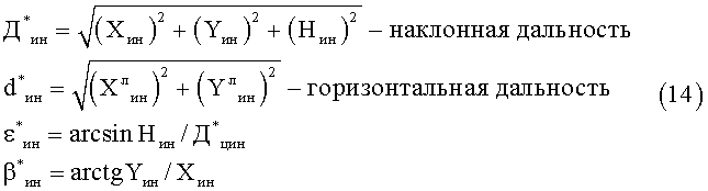
значения углов при определении величины arctgYин/Xин вычисляются с учетом зависимостей (9).the angles when determining arctgY in / X in are calculated taking into account dependencies (9).
6. По полученным данным вычисляются угловые инерционные скорости цели6. According to the data obtained, the angular inertial velocities of the target are calculated

Полученные расчетные значения углов и дальности используются для управления ПНС1 и для работы систем управления локационного 1 и оптического 2 пеленгаторов.The obtained calculated values of the angles and ranges are used to control the PNS1 and to operate the control systems of
Таким образом, использование прогнозных оценок положения цели, вырабатываемых БИС 12 исключает потерю управляемой ракеты при ее движении на траектории и позволяет, с учетом потребных скоростей и ускорений ПНС1 для выполнения ракетной стрельбы, обеспечить высокоточное сопровождение цели до возобновления прерванных локационной или оптической связей. Имея ввиду стоимость управляемой ракеты и логику работы интегрированной автоматической системы сопровождения при работе управляемым вооружением, наличие БИС 12 и инерционного режима сопровождения в системе управления принципиально необходимо.Thus, the use of predictive estimates of the target position produced by
Автоматический точный ввод ракеты в луч пеленгаторов определяет введение в состав интегрированной системы башенной установки с собственной системой наведения и предполагает синхронное подслеживание башенной установки за положением пеленгаторов. Система наведения башенной установки включает второе устройство наведения и стабилизации УНС 2 25, содержащее второй привод наведения и стабилизации 27, Ком 5 24, преобразователь координат ПК2Н-С 23, задатчик начального положения ЗНП 19 и Ком 3 8. В процессе работы интегрированной автоматической системы сопровождения согласованное положение пеленгаторов и башенной установки обеспечивается двумя структурами. В режиме сопровождения башенная установка с помощью собственного УНС 2 подслеживает за положением пеленгаторов отрабатывая сигнал углового положения пеленгаторов со второго выхода ПНС1 11, который поступает на вход УНС2 25 после преобразования в преобразователе координат ПК2н-с 23 по команде с ФЛР 3 на коммутатор Ком 5 24. В режиме заряжания (при установке в начальное положение) по команде с ФЛР 3 пеленгаторы с помощью УНС1 9 подслеживают за башенной установкой по сигналу углового положения поступающего со второго выхода МЭМ 1 31 ПНС2 27 через Ком 8 33 на четвертый вход ПНС1 11.Automatic accurate rocket entry into the beam of direction finders determines the introduction of an integrated tower installation system with its own guidance system and involves synchronous tracking of the tower installation for the position of direction finders. Guidance system tower installation comprises a second device guidance and stabilization ONS February 25, comprising a second drive guidance and
После выполнения задачи поражения цели для перезаряжания контейнеров и неиспользованных ракет по команде с ФЛР 3 башенная установка 37 приводится в положение заряжания по сигналу с ЗНП 19. После выполнения команды с ЗНП 19 контактами Ком6 30 устройство управления 28 и первый силовой блок 29 ПНС2 27 переключается на управления МЭМ2 35 привода подачи ракет 34, контакторами Ком 7 32 отключаются датчики скорости ДС2 47 и положения со второго выхода ПНС2 от второго и третьего входа УУ 28 и контакторами Ком 9 подключаются к четвертому и пятому входу УУ 28 датчики МЭМ2 35 ППР 34. По команде с ФЛР 3 Ком4 21 подключается БУЗР 20 и включается привод подъема ракет 34. Вращение от электродвигателя ИДЗ 49 через редуктор МПЗ 51 передается на звездочку 59 механизма подъема ракет 22 (МПР), приводящую в движение роликовую цепь 56 с кареткой 55. Каретка 55 перемещается вверх, подходит к пакету 58, находящемуся на направляющих башенной установке 37, входит в зацепление с пакетом 58, с ФЛР 3 подается сигнал на опускание каретки 55 с пакетом 58. Пакет 58 перемещается с направляющей башенной установки 37 на исходную позицию в барабане 60 СХП. В конце движения цепи 56 каретка 55 останавливается, нажимает на концевой выключатель при срабатывании которого выключается привод подъема ракет 34. После выключения привода подъема ракет 34, при установке пакета 58 с управляемыми ракетами в исходное положение, контактами Ком 6 30 переключаются УУ 28 и СБ1 29 на управление ИД2 46 привода ПНС2 27 башенной установки 37. Коммутаторами Ком7,9 отключаются датчики ППР 34 -по углу с Вых.2 МЭМ2 35 и по скорости ДСЗ 50 от четвертого и пятого входа УУ 28, а к второму и третьему входу УУ 28 подключаются датчики ПНС2 - по углу с Вых.2 МЭМ1 31 и по скорости ДС2 47 и включается привод башенной установки ПНС2 47.After completing the task of hitting a target for reloading containers and unused missiles, on a command with
Таким образом, в заявленном техническом решении за счет применения специальных устройств для автоматизации подготовки к пуску и пуску управляемой ракеты при использовании высокоточных локационной и телевизионной систем управления обеспечивается:Thus, in the claimed technical solution through the use of special devices to automate preparation for launch and launch of a guided missile using high-precision location-based and television control systems, it is provided:
- повышение точности и устойчивости сопровождения объектов локационным и оптико-электронным пеленгаторами при пуске ракеты;- improving the accuracy and stability of tracking objects with location and optoelectronic direction finders when launching a rocket;
- повышение надежности автосопровождения за счет уменьшения ошибок наведения и использования дополнительного контура, обеспечивающего подслеживание пеленгаторов за визируемой целью при прерывании локационной и оптической связи с целью;- improving the reliability of auto tracking by reducing guidance errors and the use of an additional circuit, which provides tracking of direction finders for the sighted target when interrupting location and optical communication with the target;
- повышенная точность ввода управляемой ракеты в луч пеленгатора с использованием башенной установки с собственным устройством наведения и стабилизации;- increased accuracy of the introduction of guided missiles into the direction finder beam using a turret with its own guidance and stabilization device;
- автоматизация процессов заряжания и перезаряжания ракет башенной установки в процессе работы интегрированной автоматической системы сопровождения.- automation of the processes of loading and reloading missiles of a turret during the operation of an integrated automatic tracking system.
Источники информацииInformation sources
1. Барсуков Ф.И., Величкин А.И., Сухарев А.Д. Телевизионные системы летательных аппаратов. - М., Советское радио, 1979. - 256 с., аналог.1. Barsukov F.I., Velichkin A.I., Sukharev A.D. Television systems of aircraft. - M., Soviet Radio, 1979. - 256 p., Analog.
2. Грязин Г.Н. Оптико-электронные системы для обзора пространства: Системы телевидения. - Л.: Машиностроение, Ленинградское отд., 1988. - 224 с.2. Gryazin G.N. Optoelectronic systems for space viewing: Television systems. - L .: Engineering, Leningrad Dep., 1988. - 224 p.
3. Цибулевский И.Е. Человек как звено следящей системы.- М., Наука, 1981. - 288 с., аналог.3. Tsibulevsky I.E. Man as a link in the tracking system. - M., Science, 1981. - 288 p., Analog.
4. Динамика следящих приводов / Под ред. Л.В. Рабиновича. - М.: Машиностроение, 1982. - 496 с., стр.132, рис.2.26, аналог.4. Dynamics of servo drives / Ed. L.V. Rabinovich. - M.: Mechanical Engineering, 1982.- 496 p., P. 132, Fig. 2.26, analogue.
5. Радиолокационные устройства / Под ред. В.В. Григорина-Рябова. - М.: Советское радио, 1970. - 680 с., стр.570, рис 21.12 аналог.5. Radar devices / Ed. V.V. Grigorina-Ryabova. - M.: Soviet Radio, 1970. - 680 p., P. 570, Fig. 21.12 analogue.
6. Патент РФ на изобретение №2327188, МПК 8 G01S 13/66, 2008 г., прототип.6. RF patent for the invention No. 23237188,
7. Максимов М.В., Горгонов Г.И. Радиоэлектронные системы самонаведения. - М., Радио и связь, 1982. - 304 с.7. Maximov M.V., Gorgonov G.I. Electronic homing systems. - M., Radio and communications, 1982. - 304 p.
8. Тетельбаум И.И., Шнейдер Ю.Р. 400 схем для АВМ. - М., Энергия, 1978. - 246 с., ил.8. Tetelbaum II, Schneider Yu.R. 400 schemes for AVM. - M., Energy, 1978.- 246 p., Ill.
9. Павлов В.В. Управляющие устройства логического типа. - М., Энергия, 1968.9. Pavlov V.V. Logical type control devices. - M., Energy, 1968.
10. Башарин А.В. и др. Управление электроприводами: Учебное пособие для вузов. - Л.: Энергоиздат. Лен. отд-ние, 1982. - 392 с.10. Basharin A.V. et al. Electric Drive Management: A Textbook for High Schools. - L.: Power Publishing House. Linen. Otdel, 1982.- 392 p.
11. Ривкин С.С. Стабилизация измерительных устройств на качающемся основании. - М., Наука, 1978. - 320 с.: ил.11. Rivkin S.S. Stabilization of measuring devices on a swinging base. - M., Nauka, 1978.- 320 p .: ill.
12. Чиликин М.Г., Сандлер А.С. Общий курс электропривода. - М., Энергоиздат, 1981. - 576 с.12. Chilikin M.G., Sandler A.S. General course of electric drive. - M., Energy Publishing House, 1981. - 576 p.
13. Бессекерский В.А., Попов Е.П. Теория систем автоматического регулирования. - М., Наука, 1973. - 768 с.13. Bessekersky V.A., Popov E.P. Theory of automatic control systems. - M., Science, 1973.- 768 p.
14. Герман-Галкин С.Г. Компьютерное моделирование полупроводниковых систем в MATLAB 6.0: Учебное пособие.- СПб: КОРОНА принт, 2001. - 320 с.14. German-Galkin S.G. Computer Simulation of Semiconductor Systems in MATLAB 6.0: A Training Manual. - St. Petersburg: CORONA print, 2001. - 320 p.
15. Магнус К. Гироскоп. Теория и применение. - М., Мир, 1974. - 526 с.15. Magnus K. Gyroscope. Theory and application. - M., Mir, 1974.- 526 p.
16. Бессекерский В.А., Фабрикант Е.А. Динамический синтез систем гироскопической стабилизации. - Л., Судостроение, 1968. - 348 с.16. Bessekersky V.A., Fabricant E.A. Dynamic synthesis of gyroscopic stabilization systems. - L., Shipbuilding, 1968 .-- 348 p.
17. Пат. 2327188 РФ. Интегрированная наблюдательная система сопровождения / И.В. Степаничев, А.В. Жуков, Е.В. Александров и др. // Бюл. - 2008. - №17. - С.855.17. Pat. 2327188 of the Russian Federation. Integrated Observational Tracking System / I.V. Stepanichev, A.V. Zhukov, E.V. Aleksandrov et al. // Bull. - 2008. - No. 17. - S.855.
18. Руководство пользователя по сигнальным микропроцессорам семейства ADSP 2100 / Пер. с англ. О.В. Луневой; под ред. А.Д. Викторова, С-Пб. Гос. ун-т. - С-Пб, 1997. - 520 с.18. User Guide for signal microprocessors of the ADSP 2100 family / Per. from English O.V. Lunar under the editorship of HELL. Viktorova, St. Petersburg. Gos. un-t - St. Petersburg, 1997 .-- 520 p.
19. DESIGNERS REFERENS MANUAL.-Analog Devices Inc., USA, 1996.19. DESIGNERS REFERENS MANUAL.-Analog Devices Inc., USA, 1996.
Claims (3)
Priority Applications (1)
| Application Number | Priority Date | Filing Date | Title |
|---|---|---|---|
| RU2012119000/07A RU2498345C1 (en) | 2012-05-11 | 2012-05-11 | Integrated automatic tracking system |
Applications Claiming Priority (1)
| Application Number | Priority Date | Filing Date | Title |
|---|---|---|---|
| RU2012119000/07A RU2498345C1 (en) | 2012-05-11 | 2012-05-11 | Integrated automatic tracking system |
Publications (1)
| Publication Number | Publication Date |
|---|---|
| RU2498345C1 true RU2498345C1 (en) | 2013-11-10 |
Family
ID=49683308
Family Applications (1)
| Application Number | Title | Priority Date | Filing Date |
|---|---|---|---|
| RU2012119000/07A RU2498345C1 (en) | 2012-05-11 | 2012-05-11 | Integrated automatic tracking system |
Country Status (1)
| Country | Link |
|---|---|
| RU (1) | RU2498345C1 (en) |
Cited By (3)
| Publication number | Priority date | Publication date | Assignee | Title |
|---|---|---|---|---|
| RU2551356C1 (en) * | 2013-12-04 | 2015-05-20 | Федеральное государственное казенное военное образовательное учреждение высшего профессионального образования "Военный учебно-научный центр Военно-Морского Флота "Военно-морская академия имени Адмирала Флота Советского Союза Н.Г. Кузнецова" | Method of non-strobe automatic tracking of mobile target |
| RU2571363C2 (en) * | 2014-01-29 | 2015-12-20 | Акционерное общество "Концерн радиостроения "Вега" | Method of controlling inertial antenna drive providing stable tracking of highly manoeuvrable and high-speed aerial objects |
| RU2803285C1 (en) * | 2023-03-27 | 2023-09-12 | Акционерное общество "Всероссийский научно-исследовательский институт "Сигнал" | Automatic target tracking system |
Citations (8)
| Publication number | Priority date | Publication date | Assignee | Title |
|---|---|---|---|---|
| US5317319A (en) * | 1992-07-17 | 1994-05-31 | Hughes Aircraft Company | Automatic global radar/IR/ESM track association based on ranked candidate pairings and measures of their proximity |
| RU2219559C2 (en) * | 2001-11-29 | 2003-12-20 | Государственное унитарное предприятие "Конструкторское бюро приборостроения" | Servo system |
| RU2321020C1 (en) * | 2006-10-26 | 2008-03-27 | Государственное унитарное предприятие "Конструкторское бюро приборостроения" | Automatic integrated optical location system for tracking movable objects |
| WO2008065194A1 (en) * | 2006-12-01 | 2008-06-05 | Thales | Method of estimating the elevation of a ballistic projectile |
| RU2327188C1 (en) * | 2007-01-09 | 2008-06-20 | Государственное унитарное предприятие "Конструкторское бюро приборостроения" | Integrated tracking and surveillance system |
| GB2448599A (en) * | 2007-04-18 | 2008-10-22 | Lfk Gmbh | Utilising a semi-martingale algorithm for predicting the motion of a target |
| WO2008149351A3 (en) * | 2008-06-04 | 2010-02-25 | Bon Networks Inc. | Electronically steerable antenna system for low power consumption |
| RU2388010C1 (en) * | 2008-08-28 | 2010-04-27 | Государственное унитарное предприятие "Конструкторское бюро приборостроения" | System for tracking mobile objects |
-
2012
- 2012-05-11 RU RU2012119000/07A patent/RU2498345C1/en active
Patent Citations (8)
| Publication number | Priority date | Publication date | Assignee | Title |
|---|---|---|---|---|
| US5317319A (en) * | 1992-07-17 | 1994-05-31 | Hughes Aircraft Company | Automatic global radar/IR/ESM track association based on ranked candidate pairings and measures of their proximity |
| RU2219559C2 (en) * | 2001-11-29 | 2003-12-20 | Государственное унитарное предприятие "Конструкторское бюро приборостроения" | Servo system |
| RU2321020C1 (en) * | 2006-10-26 | 2008-03-27 | Государственное унитарное предприятие "Конструкторское бюро приборостроения" | Automatic integrated optical location system for tracking movable objects |
| WO2008065194A1 (en) * | 2006-12-01 | 2008-06-05 | Thales | Method of estimating the elevation of a ballistic projectile |
| RU2327188C1 (en) * | 2007-01-09 | 2008-06-20 | Государственное унитарное предприятие "Конструкторское бюро приборостроения" | Integrated tracking and surveillance system |
| GB2448599A (en) * | 2007-04-18 | 2008-10-22 | Lfk Gmbh | Utilising a semi-martingale algorithm for predicting the motion of a target |
| WO2008149351A3 (en) * | 2008-06-04 | 2010-02-25 | Bon Networks Inc. | Electronically steerable antenna system for low power consumption |
| RU2388010C1 (en) * | 2008-08-28 | 2010-04-27 | Государственное унитарное предприятие "Конструкторское бюро приборостроения" | System for tracking mobile objects |
Cited By (4)
| Publication number | Priority date | Publication date | Assignee | Title |
|---|---|---|---|---|
| RU2551356C1 (en) * | 2013-12-04 | 2015-05-20 | Федеральное государственное казенное военное образовательное учреждение высшего профессионального образования "Военный учебно-научный центр Военно-Морского Флота "Военно-морская академия имени Адмирала Флота Советского Союза Н.Г. Кузнецова" | Method of non-strobe automatic tracking of mobile target |
| RU2571363C2 (en) * | 2014-01-29 | 2015-12-20 | Акционерное общество "Концерн радиостроения "Вега" | Method of controlling inertial antenna drive providing stable tracking of highly manoeuvrable and high-speed aerial objects |
| RU2818790C1 (en) * | 2023-03-14 | 2024-05-06 | Акционерное общество "Всероссийский научно-исследовательский институт "Сигнал" | Automatic target tracking system (versions) |
| RU2803285C1 (en) * | 2023-03-27 | 2023-09-12 | Акционерное общество "Всероссийский научно-исследовательский институт "Сигнал" | Automatic target tracking system |
Similar Documents
| Publication | Publication Date | Title |
|---|---|---|
| EP1857831B1 (en) | Methods and systems for data link front end filters for sporadic updates | |
| RU2381524C1 (en) | Tracking system for mobile objects | |
| Berg | Estimation and prediction for maneuvering target trajectories | |
| US8204677B2 (en) | Tracking method | |
| Held et al. | TIER II plus airborne EO sensor LOS control and image geolocation | |
| RU2388010C1 (en) | System for tracking mobile objects | |
| RU2498345C1 (en) | Integrated automatic tracking system | |
| Xuan-Mung et al. | Quadcopter precision landing on moving targets via disturbance observer-based controller and autonomous landing planner | |
| Dehghani et al. | A hardware in the loop simulation testbed for vision-based leader-follower formation flight | |
| KR101408067B1 (en) | Method for improving geo-pointing performance of electro-optical device in aircraft | |
| RU2364886C1 (en) | Tracking system | |
| RU2327188C1 (en) | Integrated tracking and surveillance system | |
| Downs et al. | High-performance gimbal control for self-protection weapon systems | |
| RU2325671C1 (en) | Location-optical system for tracking moving objects | |
| RU2386108C1 (en) | Method of integrating navigation information and self-integrated inertial navigation system | |
| RU2389041C2 (en) | Combined system for tracking mobile objects | |
| Singh et al. | Design and optimal control of line of sight stabilization of moving target | |
| RU2321020C1 (en) | Automatic integrated optical location system for tracking movable objects | |
| LeCroy et al. | Comparison of navigation solutions for autonomous spacecraft from multiple sensor systems | |
| RU2695960C1 (en) | Navigation system for movable on-board manned spacecraft equipment | |
| RU2188381C2 (en) | Method for command telecontrol of missile | |
| RU2795367C1 (en) | Method of software adjustable target support | |
| RU2039680C1 (en) | Controllable parachute system for delivery of cargoes | |
| RU2735418C2 (en) | Spatial simulation model of automatic maneuverable aircraft control system | |
| Kazemy et al. | Equations of Motion Extraction for a Three Axes Gimbal System |