RU2486503C1 - Method to detect location and size of uneven formations on pipeline walls - Google Patents
Method to detect location and size of uneven formations on pipeline walls Download PDFInfo
- Publication number
- RU2486503C1 RU2486503C1 RU2011148389/28A RU2011148389A RU2486503C1 RU 2486503 C1 RU2486503 C1 RU 2486503C1 RU 2011148389/28 A RU2011148389/28 A RU 2011148389/28A RU 2011148389 A RU2011148389 A RU 2011148389A RU 2486503 C1 RU2486503 C1 RU 2486503C1
- Authority
- RU
- Russia
- Prior art keywords
- pipeline
- reflected
- accordance
- waves
- inhomogeneous
- Prior art date
Links
Images

Landscapes
- Length Measuring Devices Characterised By Use Of Acoustic Means (AREA)
- Investigating Or Analyzing Materials By The Use Of Ultrasonic Waves (AREA)
Abstract
Description
Изобретение относится к способам неразрушающего контроля и предназначено для диагностики состояния трубопроводов, используемых при добыче или для транспортировки нефти или газа, а именно для обнаружения и определения размеров различных типов неоднородных образований (структурных неоднородностей) на внутренних и внешних поверхностях стенки трубопровода.The invention relates to non-destructive testing methods and is intended to diagnose the condition of pipelines used in the production or transportation of oil or gas, namely to detect and determine the sizes of various types of inhomogeneous formations (structural inhomogeneities) on the internal and external surfaces of the pipeline wall.
Известно, что транспортировка газов или жидкостей по трубопроводам может быть затруднена либо заблокирована вследствие образования твердых фракций, глинистых суспензий или вязких жидкостей, таких как гидраты, деготь и т.п., на внутренней поверхности стенки трубопровода. Своевременная локализация и определение размеров образований такого рода является основой для эффективного предотвращения негативных последствий.It is known that the transportation of gases or liquids through pipelines can be difficult or blocked due to the formation of solid fractions, clay suspensions or viscous liquids, such as hydrates, tar, etc., on the inner surface of the pipeline wall. Timely localization and sizing of formations of this kind is the basis for the effective prevention of negative consequences.
Процесс добычи нефти и газа зачастую включает в себя бурение подземных пород, установку обсадной колонны скважины, цементирование, дальнейшую перфорацию и разрыв пласта для образования и стимуляции течения в скважину. Возможна ситуация, при которой поток может вымыть частицы из матрицы породы и образовать каверны за обсадной колонной скважины. Другим характерным дефектом магистральных трубопроводов является коррозия или эрозия стенки трубопровода, приводящая к потере металла. При этом стенка трубопровода частично замещается корродирующим либо другим материалом, что может быть рассмотрено как неоднородность.The process of oil and gas production often includes drilling underground rocks, installing the casing of the well, cementing, further perforation and fracturing to form and stimulate the flow into the well. A situation is possible in which the flow can wash particles from the rock matrix and form cavities behind the casing of the well. Another characteristic defect of the main pipelines is corrosion or erosion of the pipe wall, leading to the loss of metal. In this case, the wall of the pipeline is partially replaced by corroding or other material, which can be considered as heterogeneity.
Для диагностики состояния магистральных трубопроводов используют, в основном, ультразвуковой контроль с передачей в стенку трубопровода зондирующих импульсов ультразвуковых колебаний. В современных внутритрубных снарядах-дефектоскопах используют как контактное, так и бесконтактное возбуждение ультразвуковых волн в стенке трубопровода. Так, известны способы внутритрубного ультразвукового контроля, включающие непрерывное перемещение дефектоскопа с электроакустическим преобразователем вдоль стенки трубопровода, генерирование электроакустическим преобразователем импульсов ультразвуковых колебаний, передачу импульсов ультразвуковых колебаний в стенку трубопровода, возбуждение ультразвуковых колебаний в стенке трубопровода, отражение ультразвуковых колебаний от неоднородностей материала стенки трубопровода, передачу отраженных ультразвуковых колебаний от стенки трубопровода к электроакустическому преобразователю, запись отраженных ультразвуковых колебаний и определение по результатам измерений характера, размеров и местоположения дефектов в стенке трубопровода (см., например, патент РФ №2153163 - бесконтактная передача импульсов, или патент РФ №2156455 - контактная передача импульсов).To diagnose the condition of the main pipelines, ultrasonic monitoring is mainly used with the transmission of probing pulses of ultrasonic vibrations to the pipeline wall. Modern in-tube flaw detectors use both contact and non-contact excitation of ultrasonic waves in the pipeline wall. So, methods of in-line ultrasonic testing are known, including continuous movement of a flaw detector with an electro-acoustic transducer along the pipeline wall, generation of ultrasonic vibrations pulses by the electro-acoustic transducer, transmission of ultrasonic vibrations pulses to the pipeline wall, excitation of ultrasonic vibrations in the pipeline wall, reflection of ultrasonic vibrations from inhomogeneities of the pipeline wall material, transmission of reflected ultrasonic vibrations from ki pipeline to electrical transducer recording the reflected ultrasonic waves and determining the character based on the results of measurement, the sizes and locations of defects in the pipe wall (see, for example, patent RF №2153163 -. contactless transmission of impulses or RF patent №2156455 - contact pulse transmission).
К недостаткам указанных способов относится длительность подготовки трубопровода к пропуску внутритрубных дефектоскопов, высокая стоимость инспекции и непригодность многих трубопроводов к пропуску внутритрубных дефектоскопов. Кроме того, ультразвук распространяется на недостаточно большое расстояние, а на волновое поле оказывают значительное влияние мелкие неоднородности на поверхности, такие как шероховатость, трещиноватость и т.д. Кроме того, известные способы предназначены для обнаружения дефектов самой поверхности трубопроводов, таких как коррозия, трещины, дефекты сварных швов, и не предусматривают возможности выявления и характеристики неоднородных образований на поверхности стенки трубопровода в околотрубном пространстве (внутри и снаружи трубопровода).The disadvantages of these methods include the duration of the preparation of the pipeline to pass in-line flaw detectors, the high cost of inspection and the unsuitability of many pipelines to pass in-line flaw detectors. In addition, ultrasound extends to an insufficiently large distance, and small inhomogeneities on the surface, such as roughness, fracture, etc., have a significant effect on the wave field. In addition, the known methods are designed to detect defects in the surface of pipelines, such as corrosion, cracks, defects in welds, and do not provide for the possibility of identifying and characterizing heterogeneous formations on the surface of the wall of the pipeline in the near-pipe space (inside and outside the pipeline).
Технический результат, достигаемый при реализации изобретения, заключается в обеспечении простой, достоверной и эффективной диагностики неоднородных образований на внутренней и наружной поверхностях трубопроводов, позволяющей определить местоположение и размеры неоднородностей с достаточно высокой точностью.The technical result achieved by the implementation of the invention is to provide a simple, reliable and effective diagnosis of inhomogeneous formations on the inner and outer surfaces of pipelines, which allows to determine the location and size of inhomogeneities with fairly high accuracy.
Указанный технический результат достигается тем, что осуществляют излучение акустического сигнала звукового диапазона в стенку трубопровода, граничащую со средой, окружающей трубопровод или протекающей внутри трубопровода, и регистрацию отраженных от неоднородного образования, преломленных и прошедших сквозь него звуковых волн. Местоположение и размеры неоднородных образований определяют на основе временного, амплитудного, частотного и скоростного анализов зарегистрированных волн.The specified technical result is achieved by the fact that the acoustic signal of the sound range is emitted into the pipeline wall, bordering the medium surrounding the pipeline or flowing inside the pipeline, and registration of sound waves reflected from the inhomogeneous formation, refracted and passed through it. The location and size of inhomogeneous formations are determined on the basis of time, amplitude, frequency, and velocity analyzes of recorded waves.
О наличии неоднородного образования можно судить по наличию в принятом сигнале отраженной от него или преломленной и прошедшей сквозь него волны, а о его местоположении судят по времени прихода отраженной волны.The presence of an inhomogeneous formation can be judged by the presence in the received signal of a wave reflected from it or refracted and transmitted through it, and its location is judged by the time of arrival of the reflected wave.
Длина неоднородного образования вдоль трубы может быть определена из разницы между временами прихода волны, отраженной от первой границы между средой и неоднородностью, и волны, отраженной от второй границы между неоднородностью и средой, фазовой компоненты сигнала и скорости среды.The length of the inhomogeneous formation along the pipe can be determined from the difference between the arrival times of the wave reflected from the first boundary between the medium and the inhomogeneity, and the wave reflected from the second boundary between the inhomogeneity and the medium, the phase component of the signal, and the velocity of the medium.
Ширина неоднородного образования может быть определена из соотношения между энергиями прямой, отраженной и преломленной волн.The width of the inhomogeneous formation can be determined from the ratio between the energies of the direct, reflected, and refracted waves.
Длина и ширина неоднородного образования могут быть также определены по амплитудно-частотным спектрам измеренных прямой, отраженной от неоднородности и проходящей сквозь нее волн.The length and width of the inhomogeneous formation can also be determined from the amplitude-frequency spectra of the measured straight line reflected from the inhomogeneity and the waves passing through it.
Ширину неоднородного образования можно определять по частоте среза прямой, отраженной и проходящей волн.The width of the heterogeneous formation can be determined by the cutoff frequency of the direct, reflected and transmitted waves.
Ширина неоднородного образования на внутренней или наружной поверхности трубы может быть также определена по разнице давлений в среде, протекающей соответственно внутри или снаружи трубопровода до и после неоднородного образования.The width of the inhomogeneous formation on the inner or outer surface of the pipe can also be determined by the pressure difference in the medium flowing inside or outside the pipeline, respectively, before and after the inhomogeneous formation.
Для излучения акустического сигнала используют по меньшей мере один передающий преобразователь, который может быть расположен как на наружной поверхности трубопровода, так и на его внутренней поверхности.At least one transmitting transducer is used to emit an acoustic signal, which can be located both on the outer surface of the pipeline and on its inner surface.
Прямые, отраженные и преломленные звуковые волны регистрируют посредством по меньшей мере одного приемного преобразователя, расположенного на наружной или на втутренней поверхности трубопровода.Direct, reflected and refracted sound waves are recorded by means of at least one receiving transducer located on the outer or inner surface of the pipeline.
Передающий преобразователь одновременно может являться приемным преобразователем.The transmitting converter can simultaneously be a receiving converter.
Передающий и/или приемный преобразователь может быть пьезоэлектрическим, магнитострикционным, механическим, электрическим, электромагнитным.The transmitting and / or receiving transducer may be piezoelectric, magnetostrictive, mechanical, electrical, electromagnetic.
Для передачи зарегистрированных акустических сигналов на обработку могут быть использованы проводные средства (электрические или оптические кабели) или беспроводные.To transmit registered acoustic signals for processing, wire means (electric or optical cables) or wireless can be used.
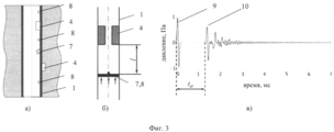
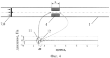
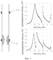
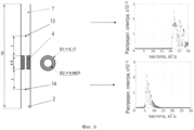
Изобретение поясняется чертежами, где на фиг.1 приведена принципиальная схема возможного расположения неоднородностей на стенках трубопровода; на фиг.2 - схема системы контроля за образованием нежелательной неоднородности в трубопроводе; на фиг.3а и 3б - примеры систем измерений для определения местоположения неоднородности; на фиг.3в - пример измеренного сигнала; на фиг.4 - пример системы измерений для определения длины неоднородности; на фиг.5 - амплитудно-частотный спектр сигнала для однородной структуры и структуры с неоднородностью, на фиг.6 - спектр отраженного сигнала и сигнала, прошедшего сквозь неоднородность, для изгибных мод.The invention is illustrated by drawings, where figure 1 shows a schematic diagram of a possible arrangement of inhomogeneities on the walls of the pipeline; figure 2 - diagram of a control system for the formation of unwanted heterogeneity in the pipeline; on figa and 3b are examples of measurement systems for determining the location of heterogeneity; on figv - an example of a measured signal; figure 4 is an example of a measurement system for determining the length of the heterogeneity; figure 5 - amplitude-frequency spectrum of the signal for a homogeneous structure and structure with heterogeneity, figure 6 - spectrum of the reflected signal and the signal transmitted through the inhomogeneity, for bending modes.
На фиг.1 схематично показан трубопровод 1, содержащий первую среду 2 внутри и окруженный второй средой 3. Среды 2 и 3 имеют неоднородности 4, которые находятся в контакте с внутренней или внешней поверхностями трубопровода 1 снаружи или внутри трубопровода. Неоднородности необязательно симметричны относительно центральной оси трубопровода 1, хотя на фиг.1 в качестве примера показан симметричный случай. Трубопровод 1 может быть любого полого профиля и состоять из различных твердых материалов. Среда 2, среда 3 и неоднородность 4 может быть газом, жидкостью или твердой фракцией.Figure 1 schematically shows a
В зависимости от размеров неоднородности вся приведенная на фиг.1 система имеет различные уникальные характеристики и реагирует по-разному, если ее подвергнуть внешнему возбуждению. Предлагаемый способ обнаружения, локализации и определения размеров неоднородностей основан на анализе акустических волн, распространяющихся в системе. Алгоритм, основанный на временном, амплитудном, частотном и скоростном анализах отраженных, преломленных и проходящих звуковых волн (объемных, головных, мод), может предоставить информацию о локализации и размерах неоднородностей.Depending on the size of the heterogeneity, the entire system shown in FIG. 1 has various unique characteristics and reacts differently if it is subjected to external excitation. The proposed method for detecting, localizing and determining the size of inhomogeneities is based on the analysis of acoustic waves propagating in the system. An algorithm based on temporal, amplitude, frequency, and velocity analyzes of reflected, refracted, and transmitted sound waves (bulk, head, modes) can provide information about the localization and size of inhomogeneities.
Система измерений состоит из массива акустических трансдьюсеров (преобразователей), работающих для отправки и получения акустических сигналов/волновых форм во времени.The measurement system consists of an array of acoustic transducers (transducers) working to send and receive acoustic signals / waveforms over time.
Массив трансдьюсеров состоит как минимум из двух трансдьюсеров, как минимум один из которых должен работать как источник, а другой - как приемник акустических сигналов.An array of transducers consists of at least two transducers, at least one of which must work as a source, and the other as a receiver of acoustic signals.
Трансдьюсер может работать и как источник, и как приемник.A transducer can work both as a source and as a receiver.
Акустический трансдьюсер может быть любым прибором, излучающим акустический сигнал или возбуждающим акустические волны/колебания на звуковых частотах в случае, если он работает как источник.An acoustic transducer can be any device that emits an acoustic signal or excites acoustic waves / vibrations at sound frequencies in case it works as a source.
Акустический трансдьюсер может быть любым прибором, способным измерять акустический сигнал, если он работает в качестве приемника.An acoustic transducer can be any instrument capable of measuring an acoustic signal if it operates as a receiver.
Акустический трансдьюсер может быть пьезоэлектрическим, магнитострикционным, механическим, электрическим, электромагнитным, например гидрофон, молот.An acoustic transducer can be piezoelectric, magnetostrictive, mechanical, electrical, electromagnetic, for example a hydrophone, a hammer.
Полученный с помощью акустического трансдьюсера массив данных должен быть передан на один и тот же обрабатывающий модуль. Это может быть сделано средствами проводных (например, электрических, оптических кабелей) или беспроводных (акустических, электрических, электромагнитных) методов.The data array obtained using the acoustic transducer must be transmitted to the same processing module. This can be done by means of wired (for example, electric, optical cables) or wireless (acoustic, electric, electromagnetic) methods.
Массив акустических трансдьюсеров должен быть размещен вдоль трубопровода и расположен внутри или снаружи трубопровода в любом месте, где возможно зарегистрировать сигнал/волну, представляющую интерес (радиальное положение каждого трансдьюсера может быть различным).An array of acoustic transducers should be placed along the pipeline and located inside or outside the pipeline at any place where it is possible to register the signal / wave of interest (the radial position of each transducer may be different).
Массив акустических трансдьюсеров может быть размещен временно (например, он может представлять собой акустический прибор, такой как DSI или Sonic Scanner (приборы Шлюмберже)) или постоянно (может быть прикреплен к стенке трубы).An array of acoustic transducers can be placed temporarily (for example, it can be an acoustic device such as a DSI or Sonic Scanner (Schlumberger devices)) or permanently (can be attached to the pipe wall).
Система контроля нежелательных образований в трубопроводе представлена на фиг.2. Например, массив акустических трансдьюсеров размещен равномерно внутри или снаружи трубопровода. Система работает последовательно: в первый момент первый трансдьюсер 5 работает как источник, остальные трансдьюсеры 6 - как приемники; во второй момент времени следующий (например, второй) трансдьюсер 6 работает как источник, остальные - как приемники; и т.д. Кроме того, может быть предложен любой оптимальный алгоритм работы данной системы.The control system of unwanted formations in the pipeline is presented in figure 2. For example, an array of acoustic transducers is placed evenly inside or outside the pipeline. The system works sequentially: at the first moment, the
Ниже приведены варианты реализации изобретения для локализации и оценки размеров неоднородности.The following are embodiments of the invention for localization and estimation of the size of heterogeneity.
Для обработки сигнала и интерпретации применяются стандартные активные методы прохождения, отражения (а также комбинированные), метод импеданса и спектральный.For signal processing and interpretation, standard active transmission, reflection (and also combined) methods, impedance and spectral methods are used.
Неоднородность может быть обнаружена путем идентификации в измеренном записанном сигнале отраженной от нее или преломленной и прошедшей сквозь нее волн. В случае отсутствия неоднородности этих волн не будет. Следовательно, вывод о существовании неоднородности может быть сделан по наличию данных волн.Heterogeneity can be detected by identifying waves reflected from it or refracted and transmitted through it in the measured recorded signal. In the absence of heterogeneity, these waves will not be. Therefore, the conclusion about the existence of heterogeneity can be made by the presence of these waves.
Времена измеряются по записанному сигналу распространения волн к неоднородности и отраженной от нее в комбинации с параметрами скорости сред, в которых распространяются эти волны, определяют местоположение неоднородности (расстояние до источника). На фиг.3а и фиг.3б показана потенциальная схема измерения, где 1 - трубопровод, 4 - неоднородность, 7 - источник, 8 - приемник; а на фиг.3в показан измеренный сигнал, где 9 - прямая волна, 10 - отраженная волна.Times are measured by the recorded wave propagation signal to the heterogeneity and reflected from it in combination with the parameters of the velocity of the media in which these waves propagate, determine the location of the heterogeneity (distance to the source). On figa and figb shows a potential measurement scheme, where 1 is the pipeline, 4 is the heterogeneity, 7 is the source, 8 is the receiver; and FIG. 3c shows a measured signal, where 9 is a direct wave, 10 is a reflected wave.
Длина неоднородности вдоль трубопровода может быть определена из разницы между временами прибытия волны (измеряются по записанному сигналу), отраженной от первой границы между средой и неоднородностью, и волны, отраженной от второй границы (неоднородность-среда), фазовой компоненты сигнала и скоростей сред. Схема на фиг.4 иллюстрирует потенциальный путь измерений и пример измеренного акустического сигнала, где 1 - трубопровод, 4 - неоднородность, 7 - источник, 8 - приемник, 11 - волна, отраженная от первой границы «среда-неоднородность», 12 - волна, отраженная от второй границы «неоднородность-среда».The length of the heterogeneity along the pipeline can be determined from the difference between the times of arrival of the wave (measured by the recorded signal) reflected from the first boundary between the medium and the heterogeneity, and the wave reflected from the second boundary (heterogeneity-medium), the phase component of the signal, and the velocities of the media. The diagram in Fig. 4 illustrates a potential measurement path and an example of a measured acoustic signal, where 1 is a pipeline, 4 is a heterogeneity, 7 is a source, 8 is a receiver, 11 is a wave reflected from the first medium-heterogeneity boundary, 12 is a wave, reflected from the second boundary “heterogeneity-environment”.
Ширина неоднородности может быть определена из соотношения между энергиями прямой, отраженной и преломленной волн. При некоторой аппроксимации (в предположение, что звуковое поле состоит из плоской волны, размеры малы по сравнению с длиной волны звука, пренебрежении сжимаемостью, …) площадь сечения неоднородности может быть посчитана из отношения амплитуд прямой и отраженной волн (см, например, Е.Скучик. Основы акустики. Том. 1. М.: Мир, 1976, 520 стр. Стр.472, пункт 3.2. Труба со скачком поперечного сечения.).The width of the inhomogeneity can be determined from the ratio between the energies of the direct, reflected, and refracted waves. With some approximation (assuming that the sound field consists of a plane wave, the dimensions are small compared to the sound wavelength, neglecting compressibility, ...) the inhomogeneity cross-sectional area can be calculated from the ratio of the amplitudes of the direct and reflected waves (see, for example, E. Skucik Fundamentals of Acoustics,
Длина и ширина неоднородности могут быть определены по амплитудно-частотным спектрам измеренных прямой, отраженной от неоднородности и проходящей сквозь нее волн. Экстремумы на измеренных амплитудно-частотных спектрах соответствуют собственным частотам рассматриваемой механической системы, которые могут быть рассчитаны на основе эквивалентной математической модели. Размеры неоднородности определяются путем решения обратной задачи. Например, для получения натурных данных необходимо возбудить в трубопроводе при помощи монопольного источника волну Стоунли и при помощи дипольного источника изгибную волну, записать сигнал и преобразовать его в амплитудно-частотный спектр. Для описания эквивалентной математической модели - рассмотреть задачу собственных радиальных и изгибных колебаний трубы с неоднородностью. Решение обратной задачи может быть получено приближенно аналитически либо численно итеративными методами. Фиг.5, где 4 - неоднородность, 7, 8 - источник/приемник, иллюстрирует пример спектра сигнала для однородной структуры и для структуры с неоднородностью. Пики спектров соответствуют собственным частотам радиальных колебаний.The length and width of the inhomogeneity can be determined from the amplitude-frequency spectra of the measured straight line reflected from the inhomogeneity and the waves passing through it. The extrema in the measured amplitude-frequency spectra correspond to the eigenfrequencies of the mechanical system under consideration, which can be calculated on the basis of an equivalent mathematical model. The dimensions of the heterogeneity are determined by solving the inverse problem. For example, to obtain field data, it is necessary to excite a Stoneley wave in a pipeline using an exclusive source and use a bending wave using a dipole source, record the signal and convert it to the amplitude-frequency spectrum. To describe an equivalent mathematical model, consider the problem of intrinsic radial and bending vibrations of a pipe with heterogeneity. The solution of the inverse problem can be obtained approximately analytically or numerically by iterative methods. Figure 5, where 4 is the heterogeneity, 7, 8 is the source / receiver, illustrates an example of a signal spectrum for a homogeneous structure and for a structure with heterogeneity. The peaks of the spectra correspond to the natural frequencies of radial vibrations.
Предельная частота (частота среза) (если таковая имеется) прямой, отраженной и проходящей волн зависит от ширины неоднородности. Например, ширина неоднородности, близкой к цилиндрической геометрии, может быть оценена аналитически по частоте среза, найденной из дисперсионного соотношения (см. Л.Ф.Лепендин. Акустика. М.: Высшая школа, 1978. 448 с. стр.330, уравнение (VI.2.13)) для задачи распространения нормальных волн в трубе. Фиг.6 иллюстрирует пример спектров отраженного сигнала и сигнала, который прошел сквозь неоднородность для изгибных мод; на фиг.6 показаны среда (вода) 2, неоднородность (гидрат) 4, источник 7, первый приемник 13, второй приемник 14.The limiting frequency (cutoff frequency) (if any) of the direct, reflected and transmitted waves depends on the width of the inhomogeneity. For example, the width of an inhomogeneity close to cylindrical geometry can be estimated analytically from the cutoff frequency found from the dispersion relation (see L.F. Lependin. Acoustics. Moscow: Vysshaya Shkola, 1978. 448 pp. P. 330, equation ( VI.2.13)) for the problem of the propagation of normal waves in a pipe. 6 illustrates an example of spectra of a reflected signal and a signal that has passed through an inhomogeneity for bending modes; figure 6 shows the medium (water) 2, heterogeneity (hydrate) 4,
Если среда 1 является текущей жидкостью, то ширина неоднородности внутри трубопровода может быть оценена на основании разницы давлений в жидкости до и после неоднородности. То же самое действительно, если среда 2 является жидкостью, и неоднородность находится снаружи трубопровода.If
Во всех вышеописанных случаях отраженная, преломленная и проходящая волны могут включать объемные, головные волны и нормальные моды (волны).In all the above cases, the reflected, refracted, and transmitted waves can include body waves, head waves, and normal modes (waves).
Claims (19)
Priority Applications (1)
| Application Number | Priority Date | Filing Date | Title |
|---|---|---|---|
| RU2011148389/28A RU2486503C1 (en) | 2011-11-29 | 2011-11-29 | Method to detect location and size of uneven formations on pipeline walls |
Applications Claiming Priority (1)
| Application Number | Priority Date | Filing Date | Title |
|---|---|---|---|
| RU2011148389/28A RU2486503C1 (en) | 2011-11-29 | 2011-11-29 | Method to detect location and size of uneven formations on pipeline walls |
Publications (2)
| Publication Number | Publication Date |
|---|---|
| RU2011148389A RU2011148389A (en) | 2013-06-10 |
| RU2486503C1 true RU2486503C1 (en) | 2013-06-27 |
Family
ID=48702354
Family Applications (1)
| Application Number | Title | Priority Date | Filing Date |
|---|---|---|---|
| RU2011148389/28A RU2486503C1 (en) | 2011-11-29 | 2011-11-29 | Method to detect location and size of uneven formations on pipeline walls |
Country Status (1)
| Country | Link |
|---|---|
| RU (1) | RU2486503C1 (en) |
Citations (8)
| Publication number | Priority date | Publication date | Assignee | Title |
|---|---|---|---|---|
| US3810384A (en) * | 1971-02-01 | 1974-05-14 | D Evans | Ultrasonic pipeline inspection device |
| US5587534A (en) * | 1994-10-28 | 1996-12-24 | The United States Of America As Represented By The Secretary Of Commerce | Wall thickness and flow detection apparatus and method for gas pipelines |
| RU2089896C1 (en) * | 1994-05-24 | 1997-09-10 | Николай Николаевич Горохов | Method of examination of defects of pipe-lines and device for its implementation |
| RU2139468C1 (en) * | 1998-08-04 | 1999-10-10 | Черняев Константин Валерьевич | Device for measuring and nondestructive testing of pipe line material |
| RU2148808C1 (en) * | 1999-06-24 | 2000-05-10 | Власов Анатолий Николаевич | Internal flaw inspection method for main pipelines |
| RU2153163C1 (en) * | 1999-11-29 | 2000-07-20 | Долгих Владимир Иванович | Method of intratube ultrasonic diagnostics of condition of pipe-line |
| RU2212660C1 (en) * | 2001-12-25 | 2003-09-20 | ЗАО "Нефтегазкомплектсервис" | Method of intratube ultrasonic testing |
| RU2344338C1 (en) * | 2007-05-16 | 2009-01-20 | Государственное Образовательное Учреждение Высшего Профессионального Образования "Дагестанский Государственный Технический Университет" (Дгту) | Method for determination of deposits thickness on internal surface of pipelines |
-
2011
- 2011-11-29 RU RU2011148389/28A patent/RU2486503C1/en not_active IP Right Cessation
Patent Citations (8)
| Publication number | Priority date | Publication date | Assignee | Title |
|---|---|---|---|---|
| US3810384A (en) * | 1971-02-01 | 1974-05-14 | D Evans | Ultrasonic pipeline inspection device |
| RU2089896C1 (en) * | 1994-05-24 | 1997-09-10 | Николай Николаевич Горохов | Method of examination of defects of pipe-lines and device for its implementation |
| US5587534A (en) * | 1994-10-28 | 1996-12-24 | The United States Of America As Represented By The Secretary Of Commerce | Wall thickness and flow detection apparatus and method for gas pipelines |
| RU2139468C1 (en) * | 1998-08-04 | 1999-10-10 | Черняев Константин Валерьевич | Device for measuring and nondestructive testing of pipe line material |
| RU2148808C1 (en) * | 1999-06-24 | 2000-05-10 | Власов Анатолий Николаевич | Internal flaw inspection method for main pipelines |
| RU2153163C1 (en) * | 1999-11-29 | 2000-07-20 | Долгих Владимир Иванович | Method of intratube ultrasonic diagnostics of condition of pipe-line |
| RU2212660C1 (en) * | 2001-12-25 | 2003-09-20 | ЗАО "Нефтегазкомплектсервис" | Method of intratube ultrasonic testing |
| RU2344338C1 (en) * | 2007-05-16 | 2009-01-20 | Государственное Образовательное Учреждение Высшего Профессионального Образования "Дагестанский Государственный Технический Университет" (Дгту) | Method for determination of deposits thickness on internal surface of pipelines |
Also Published As
| Publication number | Publication date |
|---|---|
| RU2011148389A (en) | 2013-06-10 |
Similar Documents
| Publication | Publication Date | Title |
|---|---|---|
| RU2485388C2 (en) | Device and group of sensors for pipeline monitoring using ultrasonic waves of two different types | |
| US10253615B2 (en) | Method and a system for ultrasonic inspection of well bores | |
| US10473624B2 (en) | Shear wave sensors for acoustic emission and hybrid guided wave testing | |
| JPH07318336A (en) | Method and equipment to check pipeline with ultrasonic wave | |
| US20090231954A1 (en) | Micro-Annulus Detection Using Lamb Waves | |
| US10585069B2 (en) | Detection, monitoring, and determination of location of changes in metallic structures using multimode acoustic signals | |
| US11143016B2 (en) | Method for evaluating a material on a remote side of a partition using ultrasonic measurements | |
| EP3223011A1 (en) | Ultrasonic inspection system | |
| WO2009035335A1 (en) | Acoustic thickness measurements using gas as a coupling medium | |
| CN107430096B (en) | Apparatus and method for inspecting a pipe | |
| CN112154324B (en) | Using multimode acoustic signals to detect, monitor and determine the location of changes in metal structures | |
| EP3530875A1 (en) | Method and system of evaluating cement bonds through tubing | |
| Cawley | Guided waves in long range nondestructive testing and structural health monitoring: Principles, history of applications and prospects | |
| GB2533378B (en) | Plug integrity evaluation method | |
| Klieber et al. | Visualization of leaky ultrasonic Lamb wave experiments in multilayer structures | |
| RU2486503C1 (en) | Method to detect location and size of uneven formations on pipeline walls | |
| KR101826917B1 (en) | Multi-channel ultrasonic diagnostic method for long distance piping | |
| KR100966543B1 (en) | Ultrasonic evaluation system for internal deposit layer in a pipe | |
| EP4086620A1 (en) | Method and device for checking the wall of a pipeline for flaws | |
| Singh et al. | Guided Wave Inspection Using Magnetostrictive Principle For Cement Coated Pipe Lines And Rundown Pipe Lines |
Legal Events
| Date | Code | Title | Description |
|---|---|---|---|
| MM4A | The patent is invalid due to non-payment of fees |
Effective date: 20191130 |