RU2475770C2 - Apparatus and fixing cover for dissolving and removing frozen polarised sample and container for said sample - Google Patents
Apparatus and fixing cover for dissolving and removing frozen polarised sample and container for said sample Download PDFInfo
- Publication number
- RU2475770C2 RU2475770C2 RU2010105972/28A RU2010105972A RU2475770C2 RU 2475770 C2 RU2475770 C2 RU 2475770C2 RU 2010105972/28 A RU2010105972/28 A RU 2010105972/28A RU 2010105972 A RU2010105972 A RU 2010105972A RU 2475770 C2 RU2475770 C2 RU 2475770C2
- Authority
- RU
- Russia
- Prior art keywords
- sample
- nozzle
- specified
- fluid
- dissolution
- Prior art date
Links
Images


Classifications
-
- G—PHYSICS
- G01—MEASURING; TESTING
- G01N—INVESTIGATING OR ANALYSING MATERIALS BY DETERMINING THEIR CHEMICAL OR PHYSICAL PROPERTIES
- G01N1/00—Sampling; Preparing specimens for investigation
- G01N1/28—Preparing specimens for investigation including physical details of (bio-)chemical methods covered elsewhere, e.g. G01N33/50, C12Q
- G01N1/44—Sample treatment involving radiation, e.g. heat
-
- G—PHYSICS
- G01—MEASURING; TESTING
- G01R—MEASURING ELECTRIC VARIABLES; MEASURING MAGNETIC VARIABLES
- G01R33/00—Arrangements or instruments for measuring magnetic variables
- G01R33/20—Arrangements or instruments for measuring magnetic variables involving magnetic resonance
- G01R33/28—Details of apparatus provided for in groups G01R33/44 - G01R33/64
- G01R33/30—Sample handling arrangements, e.g. sample cells, spinning mechanisms
- G01R33/307—Sample handling arrangements, e.g. sample cells, spinning mechanisms specially adapted for moving the sample relative to the MR system, e.g. spinning mechanisms, flow cells or means for positioning the sample inside a spectrometer
-
- A—HUMAN NECESSITIES
- A61—MEDICAL OR VETERINARY SCIENCE; HYGIENE
- A61J—CONTAINERS SPECIALLY ADAPTED FOR MEDICAL OR PHARMACEUTICAL PURPOSES; DEVICES OR METHODS SPECIALLY ADAPTED FOR BRINGING PHARMACEUTICAL PRODUCTS INTO PARTICULAR PHYSICAL OR ADMINISTERING FORMS; DEVICES FOR ADMINISTERING FOOD OR MEDICINES ORALLY; BABY COMFORTERS; DEVICES FOR RECEIVING SPITTLE
- A61J1/00—Containers specially adapted for medical or pharmaceutical purposes
- A61J1/14—Details; Accessories therefor
- A61J1/20—Arrangements for transferring or mixing fluids, e.g. from vial to syringe
- A61J1/2003—Accessories used in combination with means for transfer or mixing of fluids, e.g. for activating fluid flow, separating fluids, filtering fluid or venting
- A61J1/2006—Piercing means
- A61J1/2013—Piercing means having two piercing ends
-
- B—PERFORMING OPERATIONS; TRANSPORTING
- B01—PHYSICAL OR CHEMICAL PROCESSES OR APPARATUS IN GENERAL
- B01F—MIXING, e.g. DISSOLVING, EMULSIFYING OR DISPERSING
- B01F21/00—Dissolving
- B01F21/20—Dissolving using flow mixing
-
- B—PERFORMING OPERATIONS; TRANSPORTING
- B01—PHYSICAL OR CHEMICAL PROCESSES OR APPARATUS IN GENERAL
- B01L—CHEMICAL OR PHYSICAL LABORATORY APPARATUS FOR GENERAL USE
- B01L3/00—Containers or dishes for laboratory use, e.g. laboratory glassware; Droppers
-
- G—PHYSICS
- G01—MEASURING; TESTING
- G01N—INVESTIGATING OR ANALYSING MATERIALS BY DETERMINING THEIR CHEMICAL OR PHYSICAL PROPERTIES
- G01N1/00—Sampling; Preparing specimens for investigation
- G01N1/28—Preparing specimens for investigation including physical details of (bio-)chemical methods covered elsewhere, e.g. G01N33/50, C12Q
- G01N1/38—Diluting, dispersing or mixing samples
-
- B—PERFORMING OPERATIONS; TRANSPORTING
- B01—PHYSICAL OR CHEMICAL PROCESSES OR APPARATUS IN GENERAL
- B01L—CHEMICAL OR PHYSICAL LABORATORY APPARATUS FOR GENERAL USE
- B01L3/00—Containers or dishes for laboratory use, e.g. laboratory glassware; Droppers
- B01L3/02—Burettes; Pipettes
- B01L3/0289—Apparatus for withdrawing or distributing predetermined quantities of fluid
- B01L3/0293—Apparatus for withdrawing or distributing predetermined quantities of fluid for liquids
-
- G—PHYSICS
- G01—MEASURING; TESTING
- G01N—INVESTIGATING OR ANALYSING MATERIALS BY DETERMINING THEIR CHEMICAL OR PHYSICAL PROPERTIES
- G01N1/00—Sampling; Preparing specimens for investigation
- G01N1/02—Devices for withdrawing samples
- G01N1/10—Devices for withdrawing samples in the liquid or fluent state
- G01N2001/1006—Dispersed solids
- G01N2001/1012—Suspensions
- G01N2001/1025—Liquid suspensions; Slurries; Mud; Sludge
-
- G—PHYSICS
- G01—MEASURING; TESTING
- G01N—INVESTIGATING OR ANALYSING MATERIALS BY DETERMINING THEIR CHEMICAL OR PHYSICAL PROPERTIES
- G01N1/00—Sampling; Preparing specimens for investigation
- G01N1/28—Preparing specimens for investigation including physical details of (bio-)chemical methods covered elsewhere, e.g. G01N33/50, C12Q
- G01N1/38—Diluting, dispersing or mixing samples
- G01N2001/383—Diluting, dispersing or mixing samples collecting and diluting in a flow of liquid
-
- G—PHYSICS
- G01—MEASURING; TESTING
- G01R—MEASURING ELECTRIC VARIABLES; MEASURING MAGNETIC VARIABLES
- G01R33/00—Arrangements or instruments for measuring magnetic variables
- G01R33/20—Arrangements or instruments for measuring magnetic variables involving magnetic resonance
- G01R33/28—Details of apparatus provided for in groups G01R33/44 - G01R33/64
- G01R33/282—Means specially adapted for hyperpolarisation or for hyperpolarised contrast agents, e.g. for the generation of hyperpolarised gases using optical pumping cells, for storing hyperpolarised contrast agents or for the determination of the polarisation of a hyperpolarised contrast agent
-
- G—PHYSICS
- G01—MEASURING; TESTING
- G01R—MEASURING ELECTRIC VARIABLES; MEASURING MAGNETIC VARIABLES
- G01R33/00—Arrangements or instruments for measuring magnetic variables
- G01R33/20—Arrangements or instruments for measuring magnetic variables involving magnetic resonance
- G01R33/62—Arrangements or instruments for measuring magnetic variables involving magnetic resonance using double resonance
Landscapes
- Physics & Mathematics (AREA)
- Health & Medical Sciences (AREA)
- Chemical & Material Sciences (AREA)
- General Physics & Mathematics (AREA)
- General Health & Medical Sciences (AREA)
- Life Sciences & Earth Sciences (AREA)
- Biochemistry (AREA)
- Pathology (AREA)
- Immunology (AREA)
- Analytical Chemistry (AREA)
- Chemical Kinetics & Catalysis (AREA)
- Condensed Matter Physics & Semiconductors (AREA)
- Animal Behavior & Ethology (AREA)
- Pharmacology & Pharmacy (AREA)
- Public Health (AREA)
- Fluid Mechanics (AREA)
- Clinical Laboratory Science (AREA)
- Veterinary Medicine (AREA)
- Sampling And Sample Adjustment (AREA)
- Investigating Or Analysing Biological Materials (AREA)
- Magnetic Resonance Imaging Apparatus (AREA)
- Polarising Elements (AREA)
Abstract
Description
ОБЛАСТЬ ИЗОБРЕТЕНИЯFIELD OF THE INVENTION
Настоящее изобретение направлено на область динамической поляризации ядер (ДПЯ). Более конкретно, настоящее изобретение направлено на элемент оборудования для динамической поляризации ядер. Еще более конкретно, настоящее изобретение направлено на элемент оборудования для растворения для ДПЯ-поляризатора, а именно на насадку как часть устройства растворения. Эта насадка обеспечивает более эффективное растворение твердого поляризованного образца, обеспечивая, таким образом, осуществление быстрого и полного растворения.The present invention is directed to the field of dynamic polarization of nuclei (DPJ). More specifically, the present invention is directed to an element of equipment for dynamic polarization of nuclei. Even more specifically, the present invention is directed to an element of dissolution equipment for a DNP polarizer, namely, a nozzle as part of a dissolution device. This nozzle provides a more efficient dissolution of the polarized solid sample, thus providing a quick and complete dissolution.
ПРЕДПОСЫЛКИ ИЗОБРЕТЕНИЯBACKGROUND OF THE INVENTION
ДПЯ-поляризация в твердом теле, то есть при очень низких температурах и в магнитном поле от умеренного до высокого, сопровождаемая растворением с помощью среды растворения, была продемонстрирована как приводящая к чрезвычайно увеличенной поляризации ядер, которая, в свою очередь, обеспечивает ряд новых МР-применений. Пируват, например, представляет собой состав, который играет роль в цикле лимонной кислоты, причем ДПЯ-поляризованный (гиперполяризованный) пируват может использоваться как МР-агент для проведения in vivo МР-экспериментов по изучению метаболических процессов в человеческом теле. Гиперполяризованный пируват может, например, использоваться как МР-агент получения изображений для in vivo получения изображений опухоли, как описано подробно в международной патентной заявке WO 2006/011810, и для оценки жизнеспособности миокардиальной ткани с помощью МР-получения изображений, как описано подробно в международной патентной заявке №2006/054903. Чтобы произвести гиперполяризованный пируват, осуществляют ДПЯ-поляризацию пировиноградной кислоты, а затем замороженную твердую поляризованную пировиноградную кислоту растворяют и нейтрализуют в горячей среде растворения, содержащей водный буферный раствор и основание. Международная патентная заявка WO 2006/011809, которая раскрывает ДПЯ-поляризацию и растворение пировиноградной кислоты, включена в этот документ посредством ссылки, как будто бы полностью была приведена здесь.The DNP polarization in a solid, that is, at very low temperatures and in a moderate to high magnetic field, accompanied by dissolution using a dissolution medium, has been demonstrated as leading to extremely increased nuclear polarization, which, in turn, provides a number of new MR applications. Pyruvate, for example, is a composition that plays a role in the citric acid cycle, and DPJ-polarized (hyperpolarized) pyruvate can be used as an MR agent to conduct in vivo MP experiments to study metabolic processes in the human body. Hyperpolarized pyruvate can, for example, be used as an MR imaging agent for in vivo imaging of a tumor, as described in detail in international patent application WO 2006/011810, and for assessing the viability of myocardial tissue using MR imaging, as described in detail in international Patent Application No. 2006/054903. In order to produce hyperpolarized pyruvate, the DNP-polarization of pyruvic acid is carried out, and then the frozen solid polarized pyruvic acid is dissolved and neutralized in a hot dissolution medium containing an aqueous buffer solution and a base. International patent application WO 2006/011809, which discloses the DNP polarization and dissolution of pyruvic acid, is incorporated herein by reference, as if fully recited herein.
Процесс самого растворения должен быть чрезвычайно быстрым и полным. Это, в целом, требует введения горячей среды растворения в пузырек, содержащий замороженный твердый образец, с ожиданием, что тепловая энергия и поток среды растворения будут достаточны, чтобы полностью растворить образец и перенести его в другой контейнер, см., например, международную патентную заявку WO 02/37132, которая включена в этот документ посредством ссылки. В последующем термины "твердый замороженный образец", "твердый образец" и "замороженный образец" используется попеременно. Однако при попытке фактического применения этого процесса на практике наблюдалось много неожиданных проблем. Один возможный режим отказа состоял в том, что система замерзает до того, как растворился твердый образец, приводя к тому, что образуется ледяная пробка, которая частично или полностью блокирует поток в систему и из нее. Второй режим отказа состоял в том, что тепловая энергия, переданная твердому образцу, не была достаточна, чтобы растворить этот образец полностью, приводя к тому, что некоторое количество твердого образца оставалось в пузырьке. В дополнение к рабочему давлению и температуре было определено, что конструкция трубы входного отверстия и ее расположение могут играть важную роль в получении удовлетворительного растворения.The dissolution process itself must be extremely quick and complete. This generally requires the introduction of a hot dissolution medium into a vial containing a frozen solid sample, with the expectation that the heat energy and dissolution medium flow will be sufficient to completely dissolve the sample and transfer it to another container, see, for example, international patent application WO 02/37132, which is incorporated herein by reference. In the following, the terms “solid frozen sample”, “solid sample” and “frozen sample” are used interchangeably. However, when trying to actually put this process into practice, many unexpected problems were observed. One possible failure mode was that the system freezes before the solid sample has dissolved, resulting in an ice plug that partially or completely blocks the flow into and out of the system. The second failure mode was that the thermal energy transferred to the solid sample was not sufficient to completely dissolve the sample, resulting in some solid sample remaining in the bubble. In addition to the operating pressure and temperature, it was determined that the design of the inlet pipe and its location can play an important role in obtaining satisfactory dissolution.
Один предшествующий подход решения этой проблемы вовлекает нагревание среды растворения до очень высокой температуры и осуществление работы при очень высоких давлениях. При использовании этого подхода возможно быстро растворить криогенно замороженный образец. К сожалению, давления и температуры, требуемые для этого подхода, могут также потребовать дорогостоящих компонентов, изготовленных из материала, способного выдерживать высокие температуры и давления и/или привести к проблемам, связанным с безопасностью. Кроме того, очень высокие температуры легко могут привести к выпариванию среды растворения в зависимости от давления. Пар, однако, является менее эффективным для передачи тепла к замороженному твердому образцу и, таким образом, для растворения этого образца по сравнению с жидкой средой растворения. Поэтому важным является наличие средств для предотвращения выпаривания горячей среды растворения.One prior approach to solving this problem involves heating the dissolution medium to a very high temperature and operating at very high pressures. Using this approach, it is possible to quickly dissolve a cryogenically frozen sample. Unfortunately, the pressures and temperatures required for this approach may also require expensive components made from a material that can withstand high temperatures and pressures and / or lead to safety problems. In addition, very high temperatures can easily lead to evaporation of the dissolution medium depending on pressure. Steam, however, is less effective for transferring heat to a frozen solid sample and, therefore, for dissolving this sample compared to a liquid dissolution medium. Therefore, it is important to have means to prevent evaporation of the hot dissolution medium.
Кроме того, длительное растворение самопроизвольно влияет на ядерную поляризацию, поскольку поляризация в растворенном образце спадает с течением времени, при этом изменения во времени приведут к ненадежному процессу растворения, приводящему к переменной поляризации. Дополнительно, неполное растворение будет воздействовать на выход процесса. Кроме того, в случае поляризации свободной кислоты, такой как пировиноградная кислота, которая должна быть нейтрализована после растворения, неполное растворение сильно нежелательно для управления pH-фактором получающегося раствора. Поэтому желательно использовать особенности, которые способствуют надежному и целенаправленному процессу растворения.In addition, prolonged dissolution spontaneously affects nuclear polarization, since the polarization in the dissolved sample decreases over time, and changes in time will lead to an unreliable dissolution process, leading to variable polarization. Additionally, incomplete dissolution will affect the yield of the process. In addition, in the case of polarization of a free acid, such as pyruvic acid, which must be neutralized after dissolution, incomplete dissolution is highly undesirable for controlling the pH of the resulting solution. Therefore, it is desirable to use features that contribute to a reliable and targeted dissolution process.
КРАТКОЕ ОПИСАНИЕ ЧЕРТЕЖЕЙBRIEF DESCRIPTION OF THE DRAWINGS
Фиг.1 изображает зонд растворения и контейнер для образца предшествующего уровня техники.Figure 1 depicts a dissolution probe and a container for a sample of the prior art.
Фиг.2 изображает первый вариант выполнения настоящего изобретения, стыковочный модуль, содержащий насадку.Figure 2 depicts a first embodiment of the present invention, a docking module containing a nozzle.
Фиг.3 изображает второй вариант выполнения настоящего изобретения.Figure 3 depicts a second embodiment of the present invention.
Фиг.4 изображает третий вариант выполнения настоящего изобретения.Figure 4 depicts a third embodiment of the present invention.
Фиг.5 изображает четвертый вариант выполнения настоящего изобретения.5 depicts a fourth embodiment of the present invention.
Фиг.6 изображает пятый вариант выполнения настоящего изобретения.6 depicts a fifth embodiment of the present invention.
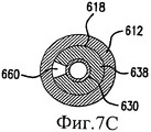
Фиг.7A-C изображают дополнительные варианты выполнения насадки, изображенной на Фиг.6.Figa-C depict additional embodiments of the nozzle depicted in Fig.6.
Фиг.8A-B изображают шестой вариант выполнения настоящего изобретения.8A-B depict a sixth embodiment of the present invention.
Фиг.9 изображает седьмой вариант выполнения настоящего изобретения, показывающий насадку, выполненную в соответствии с настоящим изобретением, в его местоположении внутри пути потока текучей среды поляризатора.Fig.9 depicts a seventh embodiment of the present invention, showing the nozzle made in accordance with the present invention, at its location inside the flow path of the polarizer fluid.
Фиг.10 изображает пузырек с образцом продукта и с крышкой, расположенный вокруг насадки, выполненной в соответствии с настоящим изобретением.Figure 10 depicts a vial with a sample of the product and with a cap located around the nozzle made in accordance with the present invention.
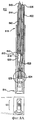
Фиг.11 изображает восьмой вариант выполнения настоящего изобретения.11 depicts an eighth embodiment of the present invention.
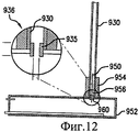
Фиг.12 изображает способ создания насадки, выполненной в соответствии с настоящим изобретением.12 depicts a method of creating a nozzle made in accordance with the present invention.
Фиг.13 показывает сравнение между растворением, когда насадка присутствует (Фиг.13B) и отсутствует (Фиг.13A).Fig. 13 shows a comparison between dissolution when a nozzle is present (Fig. 13B) and absent (Fig. 13A).
ПОДРОБНОЕ ОПИСАНИЕ ПРЕДПОЧТИТЕЛЬНЫХ ВАРИАНТОВ ВЫПОЛНЕНИЯDETAILED DESCRIPTION OF THE PREFERRED EMBODIMENTS
Фиг.1 изображает зонд 10 растворения и контейнер 12 для образца предшествующего уровня техники. Зонд 10 растворения обеспечивает растворение поляризованного материала 14 образца, содержащегося в контейнере 12 для образца.Figure 1 depicts a
Термин "образец", используемый в этом документе, относится к поляризованному материалу, который обычно содержится в контейнере для образца при низкой температуре в замороженном твердом состоянии. Термин "среда растворения" относится к жидкости, предназначенной для расплавления и растворения материала образца, образуя тем самым «раствор» расплавленного и растворенного материала образца и, возможно, также по меньшей мере части среды растворения. Температура среды растворения в целом выше, чем температура образца. Температура образца составляет приблизительно от 1 K до 5 K, тогда как температура среды растворения равна по меньшей мере комнатной температуре, то есть приблизительно 295 K, но предпочтительно нагрета, то есть используется горячая среда растворения. Если используется водная среда растворения, например водный буферный раствор, то такой водный буферный раствор может быть нагрет до температуры приблизительно 355 K или выше. Таким образом, когда среда растворения входит в контакт с образцом, образец расплавляется и растворяется. Термины "контейнер для образца" и "пузырек для образца" предполагаются означающими содержание образца и в его замороженной твердой форме, и в его форме раствора.The term “sample” as used herein refers to a polarized material that is typically contained in a sample container at a low temperature in a frozen solid state. The term “dissolution medium” refers to a fluid intended to melt and dissolve the material of a sample, thereby forming a “solution” of molten and dissolved material of the sample, and possibly also at least part of the dissolution medium. The temperature of the dissolution medium is generally higher than the temperature of the sample. The temperature of the sample is from about 1 K to 5 K, while the temperature of the dissolution medium is at least room temperature, that is, about 295 K, but preferably heated, that is, a hot dissolution medium is used. If an aqueous dissolution medium is used, for example, an aqueous buffer solution, such an aqueous buffer solution may be heated to a temperature of about 355 K or higher. Thus, when the dissolution medium comes into contact with the sample, the sample melts and dissolves. The terms “sample container” and “sample vial” are intended to mean the content of the sample in both its frozen solid form and its solution form.
Зонд 10 растворения содержит удлиненный трубчатый внешний кожух 16, имеющий противоположные первый открытый конец 18 и второй открытый конец 20. Кожух 16 имеет внутреннюю поверхность 22, которая ограничивает удлиненную полость 25, проходящую в сообщении посредством текучей среды между открытым первым концом 18 и открытым вторым концом 20. Зонд 10 растворения поддерживает первый удлиненный трубопровод 24, имеющий противоположные первый открытый конец 26 и второй открытый конец 28 и удлиненный путь 30 потока, проходящий в сообщении посредством текучей среды между открытыми концами 26 и 28. Второй открытый конец 28 предусмотрен соединенным с источником жидкой среды растворения (не показан). Зонд 10 растворения дополнительно содержит второй удлиненный трубопровод 30, имеющий противоположные первый открытый конец 32 и второй открытый конец 34, и удлиненный путь 36 выведения, проходящий в сообщении посредством текучей среды между открытыми концами 32 и 34. Путь 36 выведения обеспечивает маршрут для проведения среды растворения и растворенного материала образца, первоначально обеспечиваемого контейнером 12.The
Контейнер 12 для образца обычно содержит плоское основание 40, поддерживающее вертикальную открытую цилиндрическую стенку 42, ограничивающую приемник 44 для образца, в котором обеспечено размещение материала образца. Когда контейнер 12 вставлен в открытый конец 18 зонда 10 растворения, стенка 42 с возможностью герметизации контактирует с внутренней поверхностью 22 кожух 16, чтобы предотвратить протечку текучей среды между ними. Зонд 10 растворения и контейнер 12 ограничивают полость 50 для образца, в которой содержится материал образца, когда среда растворения подается от первого открытого конца 26 первого трубопровода 24. Смесь среды растворения и растворенного материала образца выводится из полости 50 через путь 36 выведения из второго трубопровода 30 к месту расположения приемника, где она может быть дальше обработана для получения гиперполяризованного материала, подходящего для in vitro ЯМР-анализа или для использования in vivo.The
Настоящее изобретение предусматривает использования насадки, смежной с полостью для образца, чтобы увеличить скорость потока среды растворения на материал образца. Преимущественно насадка, выполненная в соответствии с настоящим изобретением, также направляет поток среды растворения, чтобы обеспечить эффективное растворение материала образца в полости для образца. Как будет более подробно описано дополнительно, конструкция и размещение насадки могут быть оптимизированы, чтобы добиться полного и быстрого растворения материала образца. Преимущественно насадка обеспечивает поток текучей среды через полость для образца, которая способствует проведению растворенного материала образца через трубопровод выведения, и не формирует водовороты или вихри, когда растворенный материал образца заключен в полости.The present invention provides for the use of a nozzle adjacent to the cavity for the sample to increase the flow rate of the dissolution medium on the sample material. Advantageously, the nozzle made in accordance with the present invention also directs the flow of the dissolution medium to ensure efficient dissolution of the sample material in the sample cavity. As will be described in more detail below, the design and placement of the nozzle can be optimized to achieve complete and rapid dissolution of the sample material. Advantageously, the nozzle allows fluid to flow through the sample cavity, which facilitates the passage of the dissolved sample material through the withdrawal line, and does not form whirlpools or vortices when the dissolved sample material is enclosed in the cavity.
Таким образом, настоящее изобретение обеспечивает способность полного растворения криогенно замороженного образца в замкнутом пути текучей среды. Настоящее изобретение также обеспечивает способность передавать растворенный продукт от пузырька к приемнику. Дополнительно, настоящее изобретение обеспечивает способность изменять размещение насадки/внутренней трубки таким образом, чтобы полное растворение могло быть достигнуто независимо от количества материала в пузырьке. Настоящее изобретение также обеспечивает способность изменять размер и форму насадки, чтобы улучшить растворение при изменении рабочих температур и давлений. Дополнительно, настоящее изобретение обеспечивает возможность использования внутренней трубки большего диаметра, чтобы поддержать высокую массовую скорость потока, достигая при этом высокую скорость текучей среды на выходе.Thus, the present invention provides the ability to completely dissolve a cryogenically frozen sample in a closed fluid path. The present invention also provides the ability to transfer the dissolved product from the bubble to the receiver. Additionally, the present invention provides the ability to change the placement of the nozzle / inner tube so that complete dissolution can be achieved regardless of the amount of material in the bubble. The present invention also provides the ability to change the size and shape of the nozzle in order to improve dissolution when changing operating temperatures and pressures. Additionally, the present invention makes it possible to use an inner tube of a larger diameter to maintain a high mass flow rate, while achieving a high output fluid velocity.
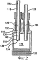
Фиг.2 изображает первый вариант выполнения настоящего изобретения, установочный кожух 110, включающий насадку. Установочный кожух 110 может быть включен в зонд растворения или отдельно включен в поляризатор в конце процесса поляризации. Установочный кожух 110 плотно посажен на контейнер 12 для образца, содержащий замороженный поляризованный образец 14. Как только контейнер 12 для образца присоединен к установочному кожуху 110, объем среды растворения посылается через трубопровод 116, который ведет в установочный кожух 110. Установочный кожух 110 имеет корпус 118, ограничивающий три отверстия: отверстие 120 среды растворения для вмещения трубопровода 116, через который подается среда растворения, отверстие 124 раствора для вмещения трубопровода 126 раствора, через который выводится раствор образца и среды растворения, и отверстие 128 образца для вмещения контейнера 12 для образца в непроницаемом для текучей среды соединении. Установочный кожух 110 ограничивает полость 125 для образца, в которой помещен замороженный поляризованный образец. Как правило, полость 125 для образца полностью ограничена между корпусом 118 и контейнером для образца (не показан), который содержит замороженный образец, предназначенный для растворения.Figure 2 depicts a first embodiment of the present invention, the
Как видно на Фиг.2, установочный кожух 110 содержит насадку 130, предусмотренную внутри отверстия 120 среды растворения. Насадка 130 содержит входное отверстие 132, отверстие 134 раздачи и путь 136 потока насадки, проходящий в сообщении посредством текучей среды между ними. Насадка 130 преимущественно имеет сужающуюся на конус внутреннюю стенку 140, которая также ограничивает путь 136 потока. Как будет понятно для каждого варианта выполнения настоящего изобретения, отверстие 134 раздачи отличается тем, что имеет площадь поперечного сечения, которая меньше, чем площадь поперечного сечения прохода 116a потока трубопровода 116. Настоящее изобретение, таким образом, выполнено с возможностью ускорения скорости потока среды растворения через отверстие 134 раздачи, по сравнению со скоростью потока через трубопровод 116 выше по потоку от отверстия 134 раздачи. Кроме того, насадки, выполненные в соответствии с настоящим изобретением, преимущественно ориентированы таким образом, что направляют поток среды растворения на замороженный образец.As can be seen in FIG. 2, the mounting
Любой специалист в этом уровне техники поймет, что конструкция насадки влияет на эффективность растворения. Здесь сужающаяся на конус внутренняя поверхность насадки сильно улучшает операцию растворения как с точки зрения прояснения всего содержимого твердого образца в контейнере для образца, так и с точки зрения обеспечения целенаправленного процесса растворения, который сохраняет ядерную поляризацию во время перехода. Как будет замечено, однако настоящее изобретение рассматривает дополнительные конструкции для насадки, выполненной в соответствии с настоящим изобретением. Дополнительно, настоящее изобретение предусматривает изготовление насадки из материала, который не реагирует с материалами, с которыми она входит в контакт, и который не будет неблагоприятно влиять на уровень поляризации материала образца.Any person skilled in the art will understand that nozzle design affects dissolution efficiency. Here, the tapering inner surface of the nozzle greatly improves the dissolution operation both from the point of view of clarifying the entire contents of the solid sample in the sample container, and from the point of view of providing a targeted dissolution process that preserves nuclear polarization during the transition. As will be seen, however, the present invention contemplates additional structures for a nozzle made in accordance with the present invention. Additionally, the present invention provides for the manufacture of a nozzle from a material that does not react with the materials with which it comes into contact, and which will not adversely affect the polarization level of the sample material.
Хотя на Фиг.2 изображена насадка 130 как часть установочного кожуха 110, настоящее изобретение также предусматривает то, что насадка 130 может быть внедрена непосредственно на свободном конце трубопровода 116. Поэтому другим применением является насадка, которая является частью замкнутого пути текучей среды, заканчивающегося на пузырьке для образца, который содержит твердый образец. Фактически, насадка представляет собой благоприятную особенность любой конструкции в контексте поляризатора, из которого образцы извлекаются путем растворения. Таким образом, также предусмотрено, что установочный кожух 10 может представлять собой крепление внутри поляризатора. Контейнер для образца тогда последовательно вставляют в установочный кожух 10 и извлекают из него, чтобы обеспечить растворение последовательных образцов в соответствии с настоящим изобретением.Although FIG. 2 depicts a
Было продемонстрировано, что диаметр концевого отверстия насадки важен в отношении эффективности растворения. Оптимальный диаметр будет, конечно, зависеть от ряда параметров, таких как глубина и форма контейнера для образца, количество образца и выбранное давление для среды растворения.It has been demonstrated that the diameter of the end opening of the nozzle is important in relation to dissolution efficiency. The optimal diameter will, of course, depend on a number of parameters, such as the depth and shape of the container for the sample, the number of samples and the selected pressure for the dissolution medium.
На Фиг.3 изображен второй вариант выполнения настоящего изобретения. Зонд 210 растворения обеспечивает растворение замороженного поляризованного материала образца, содержащегося внутри контейнера 12 для образца. Зонд 210 растворения содержит удлиненный трубчатый внешний кожух 212, имеющий противоположные первый открытый конец 214 и второй открытый конец 216, и внутреннюю поверхность 218, ограничивающую удлиненную полость 220, проходящую в сообщении посредством текучей среды между открытыми концами 214 и 216. Зонд 210 растворения поддерживает первый удлиненный трубопровод 222, имеющий противоположные первый открытый конец 224 и второй открытый конец 226. Второй открытый конец 226 трубопровода 222 выполнен с возможностью соединения с источником среды растворения. Трубопровод 222 имеет внутреннюю поверхность 228, ограничивающую удлиненный путь потока 230 для среды растворения, проходящий в сообщении посредством текучей среды между открытыми концами 224 и 226.Figure 3 shows a second embodiment of the present invention. The dissolution probe 210 dissolves the frozen polarized sample material contained within the
Зонд 210 растворения предусматривает сужающий элемент 232, имеющий первый и второй концы соответственно 234 и 236. Сужающий элемент 232 удерживается на внутренней поверхности 218 кожуха 212. Первый конец 234 сужающего элемента 232 проходит в первый открытый конец 224 трубопровода 222, чтобы уменьшить доступную площадь поперечного сечения пути 230 потока в первом открытом конце 224. Сужающий элемент 232, таким образом, вызывает ускорение среды растворения через открытый конец 224 по сравнению с ее скоростью потока в трубопроводе 222 выше по потоку. Сужающий элемент 232 дополнительно имеет внешнюю поверхность 238, которая может иметь форму или быть повернута относительно пути 230 потока так, чтобы направлять жидкость, вытекающую из первого открытого конца 224 трубопровода 222 к любому выбранному месту внутри полости 220. Конкретное направление для среды растворения, вытекающей из трубопровода 222, будет зависеть от размеров и геометрии полости 220, а также требуемой скорости потока среды растворения, поступающей в полость 220.The dissolution probe 210 provides a constriction element 232 having first and second ends 234 and 236, respectively. The constriction element 232 is held on the inner surface 218 of the casing 212. The first end 234 of the constriction element 232 extends into the first open end 224 of the pipe 222 to reduce the available cross-sectional area the flow path 230 at the first open end 224. The constriction element 232 thus causes the acceleration of the dissolution medium through the open end 224 compared to its flow rate in the pipe 222 upstream. The constricting element 232 further has an outer surface 238 that can be shaped or rotated relative to the flow path 230 so as to direct fluid flowing from the first open end 224 of conduit 222 to any selected location within the cavity 220. Specific direction for the dissolution medium arising from pipeline 222 will depend on the size and geometry of the cavity 220, as well as the required flow rate of the dissolution medium entering the cavity 220.
Зонд 210 растворения также поддерживает второй удлиненный трубопровод 240, имеющий первый и второй открытые концы соответственно 242 и 244. Трубопровод 240 ограничивает удлиненный путь 246 выведения, проходящий в сообщении посредством текучей среды между открытыми концами 242 и 244. Второй открытый конец 244 трубопровода 240 выполнен с возможностью соединения с коллектором или приемником для раствора, выведенного из полости 220.The dissolution probe 210 also supports a second elongated conduit 240 having first and second open ends 242 and 244, respectively. A conduit 240 delimits an elongated outlet path 246 in fluid communication between the open ends 242 and 244. The second open end 244 of conduit 240 is provided with the ability to connect to a collector or receiver for a solution withdrawn from the cavity 220.
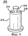
На Фиг.4 изображен третий вариант выполнения настоящего изобретения, контейнер 310 для образца для вмещения замороженного поляризованного материала внутри зонда растворения или установочного кожуха, выполненных в соответствии с настоящим изобретением. Контейнер 310 для образца содержит корпус 312, ограничивающий приемник 314 для образца, предназначенный для получения замороженного поляризованного материала образца. Корпус 312 контейнера выполнен с возможностью соединения с устройством для растворения и выведения растворенного поляризованного материала, таким как зонд растворения или установочный кожух. Конкретное устройство содержит первый трубопровод для подачи среды растворения с первой скоростью текучей среды, и второй трубопровод для выведения поляризованного материала после его растворения. Корпус 312 контейнера поддерживает насадку 316, находящуюся в перекрывающем сверху контакте с приемником 314 для образца, чтобы ускорить среду растворения до второй скорости текучей среды, большей чем первая скорость текучей среды. Скоба 318 насадки гарантирует надлежащее расположение насадки 316 относительно трубопровода среды растворения. Таким образом, насадка 316 размещена над открытым концом трубопровода среды растворения так, чтобы вся среда растворения, протекающая через трубопровод среды растворения, выходила через отверстие 318 раздачи насадки. Отверстие 318 раздачи отличается меньшей площадью поперечного сечения, чем трубопровод среды растворения, сверху которого он размещен.4 depicts a third embodiment of the present invention, a
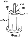
На Фиг.5 изображен четвертый вариант выполнения настоящего изобретения, контейнер 410 для образца, предназначенный для хранения замороженного поляризованного материала образца внутри зонда растворения или установочного кожуха. Контейнер 410 для образца содержит корпус 412, ограничивающий приемник 414 для образца, предназначенный для получения замороженного поляризованного материала образца. Корпус 412 контейнера выполнен с возможностью соединения с устройством для растворения и выведения растворенного поляризованного материала, таким как зонд растворения или установочный кожух. Конкретное устройство содержит первый трубопровод для подачи среды растворения с первой скоростью текучей среды, и второй трубопровод для выведения поляризованного материала после его растворения. Корпус 412 контейнера поддерживает ограничитель 416, находящийся в перекрывающем сверху контакте с приемником 414 для образца, чтобы ускорить среду растворения до второй скорости текучей среды, большей чем первая скорость текучей среды. Скоба 418 ограничителя гарантирует надлежащее расположение ограничителя 416 относительно трубопровода среды растворения. Таким образом, ограничитель 416 помещен частично в открытый конец трубопровода среды растворения так, что вся среда растворения, текущая через трубопровод среды растворения, должна выходить из трубопровода через сформированное таким образом отверстие раздачи. Отверстие раздачи отличается меньшей площадью поперечного сечения, перекрывающего пространство между ограничителем 41 и внутренней стенкой трубопровода, чем площадь поперечного сечения трубопровода среды растворения выше по потоку от ограничителя 416.5 depicts a fourth embodiment of the present invention, a
На Фиг.6 изображен пятый вариант выполнения настоящего изобретения, зонд 610 растворения, предназначенный для растворения замороженного поляризованного материала образца. Зонд 10 растворения обеспечивает растворение поляризованного материала образца, содержащегося внутри контейнера 12 для образца, который был вставлен в зонд растворения. Зонд 610 растворения является по существу модификацией зонда 10 растворения, т.е. также содержит насадку, выполненную в соответствии с настоящим изобретением, хотя направление потока жидкости полностью изменено. Зонд 610 растворения содержит удлиненный трубчатый внешний кожух 612, имеющий противоположные первый открытый конец 614 и второй открытый конец 616. Кожух 612 содержит внутреннюю поверхность 618 определений удлинять полость 620, проходящую в сообщении посредством текучей среды между открытыми концами 614 и 616.6 depicts a fifth embodiment of the present invention, a
Часть открытого конца 614 рядом с полостью 620 образует полость 625 для образца, в который вставляется контейнер 12 для образца. Зонд 610 растворения поддерживает удлиненный трубопровод 622 среды растворения, имеющий первый и второй открытые концы соответственно 624 и 626, и удлиненный путь 628 потока среды растворения, проходящий в сообщении посредством текучей среды между ними. Зонд 610 растворения дополнительно содержит удлиненный трубопровод 630 раствора, имеющий первый и второй открытые концы соответственно 632 и 634, и удлиненный путь 636 выведения, проходящий в сообщении посредством текучей среды между ними. Для герметизации внешнего кожуха 612 предусмотрена прокладка 635, таким образом, что поток жидкости остается ограниченным трубопроводами 622 и 630 и полостью 625 для образца.A portion of the
Первый открытый конец 624 из первого трубопровода 622 помещен внутри полости 618 внешнего кожуха 612 выше по потоку от первого открытого конца 632 второго трубопровода 630. Первый открытый конец 632 второго трубопровода 630 центрально поддерживается внутри полости 620 внешнего кожуха 612 кольцевой опорой 638. Как можно видеть из Фиг.7A, кольцевая опора 638 ограничивает отверстия 640 и 642 потока в местах между вторым трубопроводом 630 и внутренней поверхностью 618 внешнего кожуха 612. В соответствии с настоящим изобретением полная площадь поперечного сечения, обеспечиваемая отверстиями 640 и 642 потока, меньше, чем полная площадь поперечного сечения отверстия 644 раздачи, ограниченного первым открытым концом 624 первого трубопровода 622.The first
На Фиг.7B-C изображены дополнительные варианты выполнения насадок, выполненных в соответствии с настоящим изобретением, включенных в зонд растворения, изображенный на Фиг.6. На Фиг.7B кольцевая опора 638 ограничивает единственное отверстие 650 потока, расположенное на полпути между трубопроводом 630 раствора и внешним кожухом 612. На Фиг.7C кольцевая опора 638 ограничивает единственное отверстие 660 потока, проходящее от второго трубопровода 630 к внутренней поверхности 618 кожуха 612. В каждом случае полная площадь поперечного сечения отверстий потока, обеспечиваемая кольцевой опорой 638, меньше, чем площадь поперечного сечения отверстия 644 раздачи, приводя к ускоренному потоку в полость 620 для образца.FIGS. 7B-C show additional embodiments of nozzles made in accordance with the present invention included in the dissolution probe shown in FIG. 6. In FIG. 7B,
На Фиг.8A-B изображен шестой вариант выполнения настоящего изобретения, зонд 810 растворения, который обеспечивает растворение поляризованного материала образца, содержащегося внутри контейнера 12 для образца. Зонд 810 растворения имеет конструкцию, по существу идентичную конструкции зонда 10 растворения 10, но в нем предусмотрена насадка, выполненная в соответствии с настоящим изобретением. Зонд 810 растворения содержит удлиненный трубчатый внешний кожух 812, имеющий противоположные первый открытый конец 814 и второй открытый конец 816. Кожух 812 имеет внутреннюю поверхность 818, ограничивающую удлиненную полость 820, проходящую в сообщении посредством текучей среды между открытыми первым и вторым концами 814 и 816. Зонд 810 растворения также содержит первый удлиненный трубопровод 822, имеющий первый и второй открытые концы соответственно 824 и 826, и удлиненный путь 828 потока, проходящий в сообщении посредством текучей среды между ними. Второй открытый конец 826 выполнен с возможностью расположения в сообщении посредством текучей среды с источником среды растворения. Первый открытый конец 824 первого трубопровода 822 содержит насадку 825, ограничивающую отверстие 830 потока, которое имеет размер поперечного сечения меньше, чем размер поперечного сечения пути 828 потока выше по потоку от насадки 825. Настоящим изобретением предусмотрено, что насадка 825 может быть сформирована способом, описанным ниже, однако в настоящем изобретении может быть использована любая насадка, которая служит для ускорения через нее потока жидкости.FIGS. 8A-B illustrate a sixth embodiment of the present invention, a
Зонд 810 растворения дополнительно поддерживает второй удлиненный трубопровод 840, имеющий противоположные первый и второй открытые концы соответственно 842 и 844, и удлиненный путь 846 выведения, проходящий в сообщении посредством текучей среды между ними. Второй открытый конец 844 второго трубопровода 840 выполнен с возможностью расположения в сообщении посредством текучей среды с предназначенным местом выведения для среды растворения.The
На Фиг.9 и 10 изображен седьмой вариант выполнения настоящего изобретения. На Фиг.9 показана насадка 935, выполненная в соответствии с настоящим изобретением, в ее месте расположения внутри пути потока жидкости поляризатора. На Фиг.10 изображена крышка 910 пузырька, выполняющая функцию, аналогичную функции установочного кожуха, выполненного в соответствии с настоящим изобретением, которая выполнена с возможностью соединения с контейнером 912 для образца, который обеспечивает замороженный поляризованный материал 914 образца. Контейнер 912 для образца содержит открытый первый конец 916, закрытый второй конец 918 и удлиненную цилиндрическую стенку 920, проходящую между ними. Стенка 920 имеет внутреннюю поверхность 920a, ограничивающую полость 925 для образца. Крышка 910 пузырька содержит корпус 924, который ограничивает отверстие 926 для образца для вмещения с возможностью герметизации от текучей среды открытого конца 916 контейнера для образца. Полость 925 для образца, таким образом, полностью ограничена, когда контейнер 912 для образца 912 присоединен к крышке 910 пузырька.Figures 9 and 10 depict a seventh embodiment of the present invention. Figure 9 shows the
Крышка 910 пузырька дополнительно ограничивает единственное отверстие 928 потока, проходящее через нее, которое вмещает как трубопровод 930 среды растворения, так и трубопровод 932 раствора. Трубопровод 930 среды растворения концентрически поддерживается внутри трубопровода 932 раствора так, чтобы среда растворения, проходящая через трубопровод 930 среды растворения в полость 925 для образца, вызывала растворение замороженного материала образца и вытекание его из кольцевого пути 934 выведения вокруг трубопровода 930 среды растворения.The
Трубопровод 930 среды растворения дополнительно содержит первый открытый конец 936, имеющий насадку 935. Насадка 935 является сужением в пути 938 потока среды растворения, ограниченным трубопроводом 930 среды растворения, который вызывает ускорение в проходящем через нее потоке жидкости, по сравнению со скоростью потока текучей среды в трубопроводе 930 выше по потоку от насадки 935.The dissolution
Центральное расположение насадки 935 над полостью 925 для образца обеспечивает характеристики потока текучей среды, которая быстро и полностью растворяет криогенно замороженный продукт в полости 925, а также полностью вымещает раствор продукта через путь 934 выведения к окончательному местоположению, где он собирается в приемный резервуар 988, как это показано на Фиг.9.The central location of the
Со ссылкой снова на Фиг.9 шприц 980, содержащий среду растворения, соединяют с трубопроводом 930 среды растворения. При открытии клапана 982 шприц 980 может осуществлять раздачу среды растворения в трубопровод 930 среды растворения и через насадку 935 в полость 925 для образца. Раствор среды растворения и растворенный гиперполяризованный материал образца благодаря длительной подаче среды растворения из шприца 980 направляется через путь 934 выведения. Раствор направляют через клапан 984, в открытом состоянии, через фильтр 986 и в приемник 988, где раствор собирают. Настоящее изобретение подразумевает, что в конце своего продвижения фактически весь первоначально замороженный материал образца прибудет в приемник 988.Referring again to FIG. 9, a
Со ссылкой теперь на Фиг.11 настоящее изобретение дополнительно обеспечивает устройство 1010 растворения, которое может содержаться внутри поляризатора. Устройство 1010 растворения содержит первую удлиненную трубку 1012, имеющую противоположные первый конец и второй конец соответственно 1014 и 1016, и удлиненную трубчатую стенку 1018, проходящую между ними. Первый конец 1014 ограничивает первое отверстие 1020, предназначенный для размещения в проточном сообщении с источником текучей среды растворения (не показан, но аналогичен описанному на Фиг.9), и второй конец 1016, содержащий выходную насадку 1022. Выходная насадка 1022 ограничивает отверстие 1024 насадки. Трубчатая стенка 1018 ограничивает удлиненный проход 1026 доставки, проходящий между отверстиями 1020 и 1024. Отверстие 1024 насадки имеет такую форму, чтобы ускорить проходящий через нее от прохода 1026 поток текучей среды, как описано для других вариантов выполнения настоящего изобретения.With reference now to FIG. 11, the present invention further provides a
Устройство 1010 растворения содержит внешний кожух 1028, имеющий внешнюю стенку 1030 кожуха, который ограничивает полость 1032 для образца, предназначенную для размещения замороженного поляризованного образца. Полость 1032 для образца находится в сообщении посредством текучей среды с отверстием 1024 насадки. Внешняя стенка 1030 кожуха ограничивает отверстие 1034 выведения текучей среды, находящееся в сообщении посредством текучей среды с полостью 1032 для образца. Внешний кожух 1028 дополнительно содержит удлиненную внешнюю трубчатую стенку 1036, проходящую от внешней стенки кожуха 1030. Внешняя трубчатая стенка 1036 ограничивает удлиненный проход 1038 выведения, проходящий в сообщении посредством текучей среды с отверстием 1034 выведения текучей среды.The
Первая удлиненная трубка 1012 проходит внутри прохода 1038 выведения внешней трубчатой стенки 1036. Внешняя стенка 1030 кожуха кроме того ограничивает отверстие 1040 доступа для размещения через него первой удлиненной трубки 1012. Внешняя трубчатая стенка 1036 дополнительно ограничивает выходное отверстие 1042, находящееся в сообщении посредством текучей среды с проходом 1038 выведения. Настоящее изобретение дополнительно предусматривает, что первая удлиненная трубка 1012 может быть установлена с возможностью скольжения с помощью установочного рукава 1044, который поддерживает целостность прохода 1038 выведения с точки зрения текучей среды, одновременно обеспечивая выдвижение и втягивание первой удлиненной трубки 1012 внутри прохода 1038 выведения, чтобы выборочно располагать насадку 1022 относительно полости 1032 для образца.The first
Внешняя стенка 1030 кожуха дополнительно содержит удлиненную цилиндрическую сдерживающую образец стенку 1046, проходящую от поперечно ориентированной торцевой стенки 1048. Сужающаяся стенка 1050 формы усеченного конуса проходит между удлиненной цилиндрической сдерживающей образец стенкой 1046 и удлиненной внешней трубчатой стенкой 1036. Хотя стенки 1036, 1046 и 1050, как показано на Фиг.11, образуют непрерывную унитарную трубчатую стенку, настоящее изобретение дополнительно предусматривает, что сужающаяся стенка 1050 формы усеченного конуса может быть образована крышкой 910 пузырька, как это описано со ссылкой на Фиг.10, так, что сдерживающая образец стенка 1046 выполнена присоединяемой с возможностью отсоединения к стенке 1050 формы усеченного конуса, чтобы обеспечить доступ пользователя в полость 1032 для образца.The
Аналогично описанию со ссылкой на Фиг.9 устройство 1010 растворения может быть соединено со шприцем или с другим источником раздачи, содержащим среду растворения в первом конце первой удлиненной трубки. Среда растворения, таким образом, поступает в первую удлиненную трубку 1012 и через насадку 1022 в полость 1032 для образца. Раствор среды растворения и растворенный гиперполяризованный материал образца из-за непрерывной подачи среды растворения направляется через проход 1038 выведения. Раствор направляется через выходное отверстие 1034 к ожидающему приемнику. Настоящее изобретение предусматривает, что в конце своего прохождения фактически весь первоначально замороженный материал образца поступит в приемник.Similar to the description with reference to FIG. 9, the
Путем экспериментирования и моделирования было обнаружено, что для надежного достижения этой цели выгодно поместить насадку в конце внутренней трубки и разместить насадку на определенном расстоянии от замороженного образца, см. Фиг.12. Этот параметр, названный зазором, определен как расстояние между поверхностью замороженного образца и насадкой. Экспериментально было обнаружено, что чем ближе насадка размещена от поверхности, тем лучше получающееся растворение. К сожалению, было также замечено, что размещение насадки слишком близко к поверхности может привести к блокировке, если образец тает и повторно замораживается в любое время до инъекции среды растворения.Through experimentation and modeling, it was found that to reliably achieve this goal, it is advantageous to place the nozzle at the end of the inner tube and place the nozzle at a certain distance from the frozen sample, see Fig. 12. This parameter, called the gap, is defined as the distance between the surface of the frozen sample and the nozzle. It was experimentally found that the closer the nozzle is placed from the surface, the better the resulting dissolution. Unfortunately, it has also been observed that placing the nozzle too close to the surface can lead to blockage if the sample melts and re-freezes at any time prior to injection of the dissolution medium.
В предпочтительном варианте выполнения диаметр насадки равен 0,9 мм, а зазор установлен равным 5 мм. При внутреннем диаметре внешней трубы, равном 2,69 мм, и внешнем диаметре камеры, равном 1,83 мм, это приводит к соотношению площадей потока, приблизительно равному 1,6 в пользу выхода из системы.In a preferred embodiment, the nozzle diameter is 0.9 mm and the gap is set to 5 mm. With an inner diameter of the outer pipe of 2.69 mm and an outer diameter of the chamber of 1.83 mm, this leads to a ratio of flow areas of approximately 1.6 in favor of exiting the system.
На Фиг.12 изображен один способ создания насадки 935, выполненной в соответствии с настоящим изобретением. Насадка 935 подготовлена путем размещения первого конца 936 трубопровода 930 среды растворения сверху удлиненного вертикально проходящего стержня 950, который поддерживается нагревательным узлом 952. Нагревательный узел 952 представляет собой преимущественно электротермическое устройство, которое нагревается после подачи электроэнергии. Удлиненная цилиндрическая латунная направляющая 954, ограничивающая проходящий через нее удлиненный проход 956 трубопровода, концентрически поддерживается вокруг стержня 950. Когда нагревательный узел 952 нагревается до температуры плавления материала трубопровода, материал трубопровода начинает течь к стержню 950. Трубопровод 930 может быть еще больше приближен к нагревательному узлу 952 по мере протекания материала трубопровода. Открытый конец 936 трубопровода 930, таким образом, заново формируется вокруг стержня 950. Когда вновь сформированный трубопровод достаточно охладился, трубопровод 930 может быть выведен из латунной направляющей 954 и от стержня 950.12 depicts one method for creating a
Для дальнейшей помощи в формировании насадки 935 в нагревательном узле 952 может быть выполнена вмещающая трубопровод выемка 960, в которую сначала вставляют открытый конец 936. Стержень 950 в этом случае центрально удерживается в выемке 960. Дополнительно предусмотрено, что нагревание узла 952 может происходить одновременно с этапом деформирования трубопровода 930. В качестве альтернативы трубопровод 930 может быть подан к уже горячему узлу 952, чтобы вызвать деформацию. Этим способом в трубопроводе 930 была сформирована насадка определенной длины и диаметра. Эта технология была использована, чтобы сформировать отверстия с разным диапазоном диаметров и глубин.For further assistance in forming the
Хотя был показан и описан конкретный вариант выполнения настоящего изобретения, для специалиста в этой области техники должно быть очевидно, что могут быть сделаны изменения и модификации, не отступая от сущности изобретения. Предмет изобретения, сформулированный в предшествующем описании и сопровождающих чертежах, предлагается исключительно посредством иллюстрации, а не как ограничение. Фактический объем изобретения определен в последующей формуле изобретения, когда рассматривается в надлежащей перспективе, основываясь на уровне техники.Although a specific embodiment of the present invention has been shown and described, it should be obvious to a person skilled in the art that changes and modifications can be made without departing from the spirit of the invention. The subject matter set forth in the foregoing description and the accompanying drawings is offered by way of illustration only and not by way of limitation. The actual scope of the invention is defined in the following claims when considered in an appropriate perspective, based on the prior art.
Демонстрация действия насадки на процесс растворения приведена на Фиг.13.Demonstration of the action of the nozzle on the dissolution process is shown in Fig.13.
2,2 грамма пировиноградной кислоты было растворено в 50 мл воды (среда растворения), которая была нагрета до температуры 130°C и подвержена давлению в 17 атм (250 фунт-силы на кв. дюйм). Красный пищевой краситель был добавлен к пировиноградной кислоте, чтобы помочь в визуализации этого процесса растворения.2.2 grams of pyruvic acid was dissolved in 50 ml of water (dissolution medium), which was heated to a temperature of 130 ° C and subjected to a pressure of 17 atm (250 psi). Red food coloring has been added to pyruvic acid to help visualize this dissolution process.
На Фиг.13A показан процесс растворения в отсутствие насадки. В этом примере открытая апертура первого трубопровода составляла 1,6 мм в диаметре, результатом чего была линейная скорость текучей среды приблизительно 4 м/с. 50 мл среды растворения было потреблено приблизительно через 6 с после того, как началось растворение, причем в это время остающаяся нерасплавленная кислота не восстанавливаема из системы.13A shows a dissolution process in the absence of a nozzle. In this example, the open aperture of the first pipe was 1.6 mm in diameter, resulting in a linear fluid velocity of approximately 4 m / s. 50 ml of the dissolution medium was consumed approximately 6 seconds after the dissolution began, at which time the remaining unmelted acid was not recoverable from the system.
На Фиг.13B показан процесс растворения в присутствии сопла, т.е. насадки. В этом примере открытая апертура первого трубопровода была уменьшена до 0,9 мм в диаметре, используя ранее описанный способ изготовления насадки. С этим ограничением потока была достигнута линейная скорость текучей среды, большая чем 12 м/с. Результатом воздействия более высокоскоростной струи текучей среды было быстрое таяние центра кислотного образца (время=1 с), за которым следовало более постепенное таяние остающейся кислоты в радиальном направлении. С установленной на месте насадкой кислота была полностью расплавлена приблизительно через 4 с, задолго до того, как среда растворения была полностью потреблена.13B shows a dissolution process in the presence of a nozzle, i.e. nozzles. In this example, the open aperture of the first pipeline was reduced to 0.9 mm in diameter using the previously described method for manufacturing the nozzle. With this flow restriction, a linear fluid velocity of greater than 12 m / s was achieved. The result of the action of a higher-speed jet of fluid was the rapid melting of the center of the acid sample (time = 1 s), followed by a more gradual melting of the remaining acid in the radial direction. With the nozzle in place, the acid was completely melted after about 4 seconds, long before the dissolution medium was completely consumed.
Благодаря окончанию процесса плавления прежде, чем была потреблена среда растворения, эффективность кислотного восстановления этой системы была увеличена относительно системы без насадки.Due to the end of the melting process before the dissolution medium has been consumed, the acid reduction efficiency of this system has been increased relative to the non-packed system.
Claims (13)
корпус, выполненный с возможностью размещения в нем свободного конца трубчатого трубопровода ДПЯ-поляризатора для текучей среды, причем путь потока текучей среды указанного трубопровода помещен в проточное сообщение с насадкой, поддерживаемой указанным корпусом и выполненной с возможностью совмещения сверху с полостью для образца, в которую может быть помещен замороженный поляризованный образец, причем указанная насадка дополнительно имеет входное отверстие, отверстие раздачи и коническую внутреннюю поверхность или ступенчатую внутреннюю поверхность, ограничивающую путь потока насадки, проходящий в проточном сообщении между указанным входным отверстием и указанным отверстием раздачи,
путь выведения текучей среды, проходящий через указанный корпус кожуха и имеющий один конец, находящийся в проточном сообщении с указанной полостью для образца.1. An installation casing for dissolving and removing a polarized sample, intended for use in a DPJ polarizer, comprising:
a housing configured to accommodate the free end of the tubular pipe of the DPJ polarizer for a fluid, the fluid flow path of the pipeline being placed in fluid communication with a nozzle supported by the housing and configured to align from above with a sample cavity into which a frozen polarized sample should be placed, said nozzle additionally having an inlet, a dispensing hole and a conical inner surface or step inside friction surface defining the nozzle flow path extending in fluid communication between said inlet opening and said dispensing opening,
the path of fluid withdrawal passing through the specified casing of the casing and having one end in fluid communication with the specified cavity for the sample.
корпус, ограничивающий приемник для образца, предназначенный для содержания поляризованного образца, причем указанный корпус выполнен с возможностью взаимодействия с устройством для растворения и выведения замороженного поляризованного образца, при этом указанное устройство содержит первый трубопровод для обеспечения среды растворения с первой скоростью текучей среды, и второй трубопровод для выведения поляризованного образца после его растворения, и
насадку, поддерживаемую указанным корпусом контейнера с обеспечением совмещения сверху с указанным приемником для образца с обеспечением ускорения среды растворения до второй скорости текучей среды, большей, чем первая скорость текучей среды,
причем указанная насадка дополнительно содержит удлиненный сужающий элемент, имеющий первый конец, который проходит в первый трубопровод, когда указанный контейнер взаимодействует с устройством.7. A container for containing a frozen polarized sample, comprising:
a housing defining a sample receiver for containing a polarized sample, said housing being configured to interact with a device for dissolving and discharging a frozen polarized sample, said device comprising a first pipe for providing a dissolution medium with a first fluid velocity, and a second pipe to remove the polarized sample after its dissolution, and
a nozzle supported by the specified container body, ensuring alignment from above with the specified receiver for the sample, providing acceleration of the dissolution medium to a second fluid velocity greater than the first fluid velocity,
wherein said nozzle further comprises an elongated constricting element having a first end that extends into the first pipe when said container interacts with the device.
первую удлиненную трубку, содержащую первый конец, второй конец и удлиненную трубчатую стенку, проходящую между ними, причем указанный первый конец ограничивает первое отверстие, которое должно быть помещено в проточное сообщение с источником текучей среды растворения, а второй конец содержит выходную насадку, ограничивающую отверстие, имеющее форму, обеспечивающую ускорение потока текучей среды через указанный второй конец,
внешний кожух, содержащий внешнюю стенку, ограничивающую полость для образца для содержания замороженного поляризованного образца, причем указанная полость находится в проточном сообщении с указанной выходной насадкой, а указанная внешняя стенка кожуха дополнительно ограничивает отверстие выведения текучей среды, находящееся в проточном сообщении с указанной полостью для образца.9. A device for dissolving and removing a frozen polarized sample, containing:
a first elongated tube comprising a first end, a second end and an elongated tubular wall extending between them, said first end defining a first opening to be placed in fluid communication with a dissolution fluid source, and the second end containing an outlet nozzle defining an opening, shaped to accelerate the flow of fluid through said second end,
an outer casing containing an outer wall defining a sample cavity for containing a frozen polarized sample, said cavity being in fluid communication with said outlet nozzle, and said outer shell wall further restricting a fluid outlet in fluid communication with said specimen cavity .
Applications Claiming Priority (3)
| Application Number | Priority Date | Filing Date | Title |
|---|---|---|---|
| US96832007P | 2007-08-28 | 2007-08-28 | |
| US60/968,320 | 2007-08-28 | ||
| PCT/EP2008/061197 WO2009027422A2 (en) | 2007-08-28 | 2008-08-27 | Nozzle for a polarizer for dynamic nuclear spin polarisation (dnp) |
Related Child Applications (1)
| Application Number | Title | Priority Date | Filing Date |
|---|---|---|---|
| RU2012148805A Division RU2609497C2 (en) | 2007-08-28 | 2012-11-07 | Dissolution probe to dissolve sample polarized material |
Publications (2)
| Publication Number | Publication Date |
|---|---|
| RU2010105972A RU2010105972A (en) | 2011-10-10 |
| RU2475770C2 true RU2475770C2 (en) | 2013-02-20 |
Family
ID=40130844
Family Applications (2)
| Application Number | Title | Priority Date | Filing Date |
|---|---|---|---|
| RU2010105972/28A RU2475770C2 (en) | 2007-08-28 | 2008-08-27 | Apparatus and fixing cover for dissolving and removing frozen polarised sample and container for said sample |
| RU2012148805A RU2609497C2 (en) | 2007-08-28 | 2012-11-07 | Dissolution probe to dissolve sample polarized material |
Family Applications After (1)
| Application Number | Title | Priority Date | Filing Date |
|---|---|---|---|
| RU2012148805A RU2609497C2 (en) | 2007-08-28 | 2012-11-07 | Dissolution probe to dissolve sample polarized material |
Country Status (13)
| Country | Link |
|---|---|
| US (1) | US20110036453A1 (en) |
| EP (1) | EP2183610B1 (en) |
| JP (1) | JP5405466B2 (en) |
| KR (2) | KR101546208B1 (en) |
| CN (2) | CN101790692A (en) |
| AU (1) | AU2008292171B2 (en) |
| BR (1) | BRPI0816131A2 (en) |
| CA (1) | CA2697955A1 (en) |
| DK (1) | DK2183610T3 (en) |
| ES (1) | ES2576582T3 (en) |
| MX (1) | MX2010002195A (en) |
| RU (2) | RU2475770C2 (en) |
| WO (1) | WO2009027422A2 (en) |
Families Citing this family (7)
| Publication number | Priority date | Publication date | Assignee | Title |
|---|---|---|---|---|
| US9587215B2 (en) | 2014-08-07 | 2017-03-07 | General Electric Company | Devices, systems and methods for automated transfer of a sample |
| US10060838B2 (en) | 2015-04-09 | 2018-08-28 | Ut-Battelle, Llc | Capture probe |
| US9632066B2 (en) | 2015-04-09 | 2017-04-25 | Ut-Battelle, Llc | Open port sampling interface |
| US10481222B2 (en) * | 2017-07-24 | 2019-11-19 | General Electric Company | Fluid path insert for a cryogenic cooling system |
| US11125657B2 (en) * | 2018-01-30 | 2021-09-21 | Ut-Battelle, Llc | Sampling probe |
| KR20230159994A (en) | 2022-05-16 | 2023-11-23 | 전남대학교산학협력단 | Recombinant vector comprising hybrid signal sequence, and secretary preparation method of human insulin-like growth factor-1 using the same |
| CN116223554B (en) * | 2023-05-09 | 2023-08-04 | 中国科学院精密测量科学与技术创新研究院 | Device and method for detecting dDNP probe molecule multichannel metabolic tracking |
Citations (5)
| Publication number | Priority date | Publication date | Assignee | Title |
|---|---|---|---|---|
| EP0078109A1 (en) * | 1981-10-23 | 1983-05-04 | The University Of Birmingham | Liquid dispenser |
| EP0409650A2 (en) * | 1989-07-21 | 1991-01-23 | Helena Laboratories Corporation | Apparatus for discharging contents of a sealed container |
| US20020037251A1 (en) * | 2000-07-13 | 2002-03-28 | Bastiaan Driehuys | Diagnostic procedures using 129Xe spectroscopy characteristic chemical shift to detect pathology in vivo |
| RU2003103092A (en) * | 2000-09-12 | 2004-08-20 | Амершем Хелт АС | METHOD FOR RESEARCHING THE SAMPLE BY THE MAGNETIC RESONANCE METHOD WITH APPLICATION OF THE MAGNETIC RESONANT VISUALIZATION AGENT POLARIZED BY NUCLEAR SPIN |
| WO2004109121A1 (en) * | 2003-05-30 | 2004-12-16 | E-Z Flo Injection Systems, Inc. | Hose-end chemical delivery system |
Family Cites Families (19)
| Publication number | Priority date | Publication date | Assignee | Title |
|---|---|---|---|---|
| GB103769A (en) * | 1916-07-26 | 1917-02-08 | William Edward Silverthorne | Improvements in and relating to Pour Outs for Bottles and the like. |
| US2842465A (en) * | 1955-12-06 | 1958-07-08 | Jack Danciger | Method for cleaning tires |
| FR1187261A (en) * | 1957-11-25 | 1959-09-09 | Perforating cannula for a transfusion or infusion device and allowing a liquid to be withdrawn from a vial closed with a stopper | |
| AR206690A1 (en) * | 1973-07-05 | 1976-08-13 | Ime Ltd | FLUID TRANSFER DEVICE |
| CA1010382A (en) * | 1973-08-29 | 1977-05-17 | Beckman Instruments | Gas stream cleaning system |
| US4296786A (en) * | 1979-09-28 | 1981-10-27 | The West Company | Transfer device for use in mixing a primary solution and a secondary or additive substance |
| US4419233A (en) * | 1981-11-18 | 1983-12-06 | Baker Marvin E | Chlorinator for a swimming pool |
| JPS60104270U (en) * | 1983-12-16 | 1985-07-16 | 三菱重工業株式会社 | ice melting equipment |
| US4769159A (en) * | 1986-02-18 | 1988-09-06 | Ecolab Inc. | Institutional softener containing cationic surfactant and organic acid |
| JPH0350531A (en) * | 1989-07-19 | 1991-03-05 | Fujitsu Ltd | Semiconductor light condenser |
| US5076315A (en) * | 1990-07-23 | 1991-12-31 | King Joseph A | Dispersal valve and canister |
| JP3331089B2 (en) * | 1995-05-15 | 2002-10-07 | 理学電機株式会社 | Sample cooling nozzle |
| US5653871A (en) * | 1996-04-24 | 1997-08-05 | Everpure, Inc. | Filter assembly with O-ring protection |
| GB0022341D0 (en) * | 2000-09-12 | 2000-10-25 | Nycomed Imaging As | Method |
| CN100392422C (en) * | 2000-11-03 | 2008-06-04 | 通用电气医疗集团股份有限公司 | Method and devices for dissolving hyperpolarised solid material for nmr analyses |
| US20070145164A1 (en) * | 2005-12-22 | 2007-06-28 | Nordson Corporation | Jetting dispenser with multiple jetting nozzle outlets |
| JP5013907B2 (en) * | 2007-03-06 | 2012-08-29 | 英明 藤原 | Method for producing polarized rare gas |
| US20080240998A1 (en) * | 2007-03-28 | 2008-10-02 | Urbahn John A | Fluid path system for dissolution and transport of a hyperpolarized material |
| US7633290B1 (en) * | 2008-09-09 | 2009-12-15 | General Electric Company | Apparatus and method for a fully automated preparation of a hyperpolarizing imaging agent |
-
2008
- 2008-08-27 US US12/675,815 patent/US20110036453A1/en not_active Abandoned
- 2008-08-27 EP EP08803264.4A patent/EP2183610B1/en not_active Not-in-force
- 2008-08-27 RU RU2010105972/28A patent/RU2475770C2/en not_active IP Right Cessation
- 2008-08-27 ES ES08803264.4T patent/ES2576582T3/en active Active
- 2008-08-27 CA CA2697955A patent/CA2697955A1/en not_active Abandoned
- 2008-08-27 AU AU2008292171A patent/AU2008292171B2/en not_active Ceased
- 2008-08-27 CN CN200880105546A patent/CN101790692A/en active Pending
- 2008-08-27 CN CN201410294250.0A patent/CN104076308A/en active Pending
- 2008-08-27 BR BRPI0816131A patent/BRPI0816131A2/en not_active IP Right Cessation
- 2008-08-27 DK DK08803264.4T patent/DK2183610T3/en active
- 2008-08-27 KR KR1020147030750A patent/KR101546208B1/en not_active IP Right Cessation
- 2008-08-27 WO PCT/EP2008/061197 patent/WO2009027422A2/en active Application Filing
- 2008-08-27 MX MX2010002195A patent/MX2010002195A/en active IP Right Grant
- 2008-08-27 KR KR1020107004444A patent/KR20100055443A/en not_active Application Discontinuation
- 2008-08-27 JP JP2010522353A patent/JP5405466B2/en not_active Expired - Fee Related
-
2012
- 2012-11-07 RU RU2012148805A patent/RU2609497C2/en not_active IP Right Cessation
Patent Citations (5)
| Publication number | Priority date | Publication date | Assignee | Title |
|---|---|---|---|---|
| EP0078109A1 (en) * | 1981-10-23 | 1983-05-04 | The University Of Birmingham | Liquid dispenser |
| EP0409650A2 (en) * | 1989-07-21 | 1991-01-23 | Helena Laboratories Corporation | Apparatus for discharging contents of a sealed container |
| US20020037251A1 (en) * | 2000-07-13 | 2002-03-28 | Bastiaan Driehuys | Diagnostic procedures using 129Xe spectroscopy characteristic chemical shift to detect pathology in vivo |
| RU2003103092A (en) * | 2000-09-12 | 2004-08-20 | Амершем Хелт АС | METHOD FOR RESEARCHING THE SAMPLE BY THE MAGNETIC RESONANCE METHOD WITH APPLICATION OF THE MAGNETIC RESONANT VISUALIZATION AGENT POLARIZED BY NUCLEAR SPIN |
| WO2004109121A1 (en) * | 2003-05-30 | 2004-12-16 | E-Z Flo Injection Systems, Inc. | Hose-end chemical delivery system |
Also Published As
| Publication number | Publication date |
|---|---|
| CA2697955A1 (en) | 2009-03-05 |
| KR20140146163A (en) | 2014-12-24 |
| DK2183610T3 (en) | 2016-06-27 |
| RU2609497C2 (en) | 2017-02-02 |
| RU2010105972A (en) | 2011-10-10 |
| EP2183610A2 (en) | 2010-05-12 |
| US20110036453A1 (en) | 2011-02-17 |
| JP5405466B2 (en) | 2014-02-05 |
| AU2008292171A1 (en) | 2009-03-05 |
| BRPI0816131A2 (en) | 2017-06-13 |
| CN104076308A (en) | 2014-10-01 |
| KR101546208B1 (en) | 2015-08-20 |
| WO2009027422A3 (en) | 2009-09-03 |
| AU2008292171A2 (en) | 2010-04-29 |
| AU2008292171B2 (en) | 2014-06-05 |
| KR20100055443A (en) | 2010-05-26 |
| ES2576582T3 (en) | 2016-07-08 |
| RU2012148805A (en) | 2014-05-20 |
| EP2183610B1 (en) | 2016-03-23 |
| MX2010002195A (en) | 2010-08-02 |
| JP2010537213A (en) | 2010-12-02 |
| CN101790692A (en) | 2010-07-28 |
| WO2009027422A2 (en) | 2009-03-05 |
Similar Documents
| Publication | Publication Date | Title |
|---|---|---|
| RU2609497C2 (en) | Dissolution probe to dissolve sample polarized material | |
| CN105256288A (en) | Liquid material vaporizer | |
| CA2878146C (en) | Device for simulating the ingestion of chunks of ice by an engine | |
| CN100416189C (en) | Ice making method and device | |
| JP2010537213A5 (en) | ||
| JP2002361392A (en) | Cooling device for mold | |
| KR100774604B1 (en) | Method and system for making ice by underwater supercooling release and low temperature water supply system comprising it | |
| CN101672584A (en) | Heat exchanger and oil well paraffin removal device with same | |
| PT744578E (en) | DEVICE FOR THE INJECTION OF LIQUID UNDER PRESSURE IN A CONTAINER | |
| CN216689604U (en) | Pipeline functional module | |
| US9999862B2 (en) | Rehydration capsule and method of using the same | |
| CN210496490U (en) | Water bath box of medicine dissolving-out instrument | |
| CN220178158U (en) | Diversion type continuous casting nozzle | |
| KR20130094580A (en) | Steam thawing apparatus | |
| JP2007163069A (en) | Ice making method and ice making apparatus using supercooled water | |
| CN106345139A (en) | Extraction device and method of extracting active ingredient from solid matter | |
| KR200341557Y1 (en) | Water tank for dispenser of refrigerator | |
| JP2013144107A (en) | Fluid path system for dissolution and transport of hyperpolarized material | |
| KR101235344B1 (en) | bubble extinguisher and the method of testing the bubble extinguisher | |
| JP2006138346A (en) | Oil feeder and flashing method | |
| JPH06294717A (en) | Sampling pipe for cryogenic liquefied gas | |
| RU2011102773A (en) | SYSTEM OF DELIVERY OF SOLUTIONS TO THE CONTAINER | |
| CA2592568A1 (en) | System and method for on-line cleaning of black oil heater tubes and delayed coker heater tubes | |
| JPH1130563A (en) | Instrument and method for measuring pressure drop of liquid | |
| JP2008075900A (en) | Propagation preventing method against ice attached to wall surface |
Legal Events
| Date | Code | Title | Description |
|---|---|---|---|
| MM4A | The patent is invalid due to non-payment of fees |
Effective date: 20160828 |