RU2472557C2 - Ergometric simulator - Google Patents
Ergometric simulator Download PDFInfo
- Publication number
- RU2472557C2 RU2472557C2 RU2010111912/12A RU2010111912A RU2472557C2 RU 2472557 C2 RU2472557 C2 RU 2472557C2 RU 2010111912/12 A RU2010111912/12 A RU 2010111912/12A RU 2010111912 A RU2010111912 A RU 2010111912A RU 2472557 C2 RU2472557 C2 RU 2472557C2
- Authority
- RU
- Russia
- Prior art keywords
- drive
- measuring
- wheel
- sensor
- training device
- Prior art date
Links
Images
Classifications
-
- A—HUMAN NECESSITIES
- A63—SPORTS; GAMES; AMUSEMENTS
- A63B—APPARATUS FOR PHYSICAL TRAINING, GYMNASTICS, SWIMMING, CLIMBING, OR FENCING; BALL GAMES; TRAINING EQUIPMENT
- A63B24/00—Electric or electronic controls for exercising apparatus of preceding groups; Controlling or monitoring of exercises, sportive games, training or athletic performances
-
- A—HUMAN NECESSITIES
- A63—SPORTS; GAMES; AMUSEMENTS
- A63B—APPARATUS FOR PHYSICAL TRAINING, GYMNASTICS, SWIMMING, CLIMBING, OR FENCING; BALL GAMES; TRAINING EQUIPMENT
- A63B22/00—Exercising apparatus specially adapted for conditioning the cardio-vascular system, for training agility or co-ordination of movements
- A63B22/0002—Exercising apparatus specially adapted for conditioning the cardio-vascular system, for training agility or co-ordination of movements involving an exercising of arms
- A63B22/0005—Exercising apparatus specially adapted for conditioning the cardio-vascular system, for training agility or co-ordination of movements involving an exercising of arms with particular movement of the arms provided by handles moving otherwise than pivoting about a horizontal axis parallel to the body-symmetrical-plane
-
- A—HUMAN NECESSITIES
- A63—SPORTS; GAMES; AMUSEMENTS
- A63B—APPARATUS FOR PHYSICAL TRAINING, GYMNASTICS, SWIMMING, CLIMBING, OR FENCING; BALL GAMES; TRAINING EQUIPMENT
- A63B22/00—Exercising apparatus specially adapted for conditioning the cardio-vascular system, for training agility or co-ordination of movements
- A63B22/06—Exercising apparatus specially adapted for conditioning the cardio-vascular system, for training agility or co-ordination of movements with support elements performing a rotating cycling movement, i.e. a closed path movement
- A63B22/0605—Exercising apparatus specially adapted for conditioning the cardio-vascular system, for training agility or co-ordination of movements with support elements performing a rotating cycling movement, i.e. a closed path movement performing a circular movement, e.g. ergometers
-
- A—HUMAN NECESSITIES
- A61—MEDICAL OR VETERINARY SCIENCE; HYGIENE
- A61B—DIAGNOSIS; SURGERY; IDENTIFICATION
- A61B5/00—Measuring for diagnostic purposes; Identification of persons
- A61B5/22—Ergometry; Measuring muscular strength or the force of a muscular blow
- A61B5/221—Ergometry, e.g. by using bicycle type apparatus
- A61B5/222—Ergometry, e.g. by using bicycle type apparatus combined with detection or measurement of physiological parameters, e.g. heart rate
-
- A—HUMAN NECESSITIES
- A63—SPORTS; GAMES; AMUSEMENTS
- A63B—APPARATUS FOR PHYSICAL TRAINING, GYMNASTICS, SWIMMING, CLIMBING, OR FENCING; BALL GAMES; TRAINING EQUIPMENT
- A63B22/00—Exercising apparatus specially adapted for conditioning the cardio-vascular system, for training agility or co-ordination of movements
- A63B22/06—Exercising apparatus specially adapted for conditioning the cardio-vascular system, for training agility or co-ordination of movements with support elements performing a rotating cycling movement, i.e. a closed path movement
- A63B22/0605—Exercising apparatus specially adapted for conditioning the cardio-vascular system, for training agility or co-ordination of movements with support elements performing a rotating cycling movement, i.e. a closed path movement performing a circular movement, e.g. ergometers
- A63B2022/0635—Exercising apparatus specially adapted for conditioning the cardio-vascular system, for training agility or co-ordination of movements with support elements performing a rotating cycling movement, i.e. a closed path movement performing a circular movement, e.g. ergometers specially adapted for a particular use
- A63B2022/0658—Exercising apparatus specially adapted for conditioning the cardio-vascular system, for training agility or co-ordination of movements with support elements performing a rotating cycling movement, i.e. a closed path movement performing a circular movement, e.g. ergometers specially adapted for a particular use for cycling with a group of people, e.g. spinning classes
-
- A—HUMAN NECESSITIES
- A63—SPORTS; GAMES; AMUSEMENTS
- A63B—APPARATUS FOR PHYSICAL TRAINING, GYMNASTICS, SWIMMING, CLIMBING, OR FENCING; BALL GAMES; TRAINING EQUIPMENT
- A63B71/00—Games or sports accessories not covered in groups A63B1/00 - A63B69/00
- A63B71/06—Indicating or scoring devices for games or players, or for other sports activities
- A63B71/0619—Displays, user interfaces and indicating devices, specially adapted for sport equipment, e.g. display mounted on treadmills
- A63B2071/065—Visualisation of specific exercise parameters
- A63B2071/0652—Visualisation or indication relating to symmetrical exercise, e.g. right-left performance related to spinal column
-
- A—HUMAN NECESSITIES
- A63—SPORTS; GAMES; AMUSEMENTS
- A63B—APPARATUS FOR PHYSICAL TRAINING, GYMNASTICS, SWIMMING, CLIMBING, OR FENCING; BALL GAMES; TRAINING EQUIPMENT
- A63B21/00—Exercising apparatus for developing or strengthening the muscles or joints of the body by working against a counterforce, with or without measuring devices
- A63B21/005—Exercising apparatus for developing or strengthening the muscles or joints of the body by working against a counterforce, with or without measuring devices using electromagnetic or electric force-resisters
-
- A—HUMAN NECESSITIES
- A63—SPORTS; GAMES; AMUSEMENTS
- A63B—APPARATUS FOR PHYSICAL TRAINING, GYMNASTICS, SWIMMING, CLIMBING, OR FENCING; BALL GAMES; TRAINING EQUIPMENT
- A63B21/00—Exercising apparatus for developing or strengthening the muscles or joints of the body by working against a counterforce, with or without measuring devices
- A63B21/008—Exercising apparatus for developing or strengthening the muscles or joints of the body by working against a counterforce, with or without measuring devices using hydraulic or pneumatic force-resisters
- A63B21/0085—Exercising apparatus for developing or strengthening the muscles or joints of the body by working against a counterforce, with or without measuring devices using hydraulic or pneumatic force-resisters using pneumatic force-resisters
- A63B21/0088—Exercising apparatus for developing or strengthening the muscles or joints of the body by working against a counterforce, with or without measuring devices using hydraulic or pneumatic force-resisters using pneumatic force-resisters by moving the surrounding air
-
- A—HUMAN NECESSITIES
- A63—SPORTS; GAMES; AMUSEMENTS
- A63B—APPARATUS FOR PHYSICAL TRAINING, GYMNASTICS, SWIMMING, CLIMBING, OR FENCING; BALL GAMES; TRAINING EQUIPMENT
- A63B21/00—Exercising apparatus for developing or strengthening the muscles or joints of the body by working against a counterforce, with or without measuring devices
- A63B21/22—Resisting devices with rotary bodies
- A63B21/225—Resisting devices with rotary bodies with flywheels
-
- A—HUMAN NECESSITIES
- A63—SPORTS; GAMES; AMUSEMENTS
- A63B—APPARATUS FOR PHYSICAL TRAINING, GYMNASTICS, SWIMMING, CLIMBING, OR FENCING; BALL GAMES; TRAINING EQUIPMENT
- A63B22/00—Exercising apparatus specially adapted for conditioning the cardio-vascular system, for training agility or co-ordination of movements
- A63B22/0002—Exercising apparatus specially adapted for conditioning the cardio-vascular system, for training agility or co-ordination of movements involving an exercising of arms
- A63B22/0007—Exercising apparatus specially adapted for conditioning the cardio-vascular system, for training agility or co-ordination of movements involving an exercising of arms by alternatively exercising arms or legs, e.g. with a single set of support elements driven either by the upper or the lower limbs
-
- A—HUMAN NECESSITIES
- A63—SPORTS; GAMES; AMUSEMENTS
- A63B—APPARATUS FOR PHYSICAL TRAINING, GYMNASTICS, SWIMMING, CLIMBING, OR FENCING; BALL GAMES; TRAINING EQUIPMENT
- A63B22/00—Exercising apparatus specially adapted for conditioning the cardio-vascular system, for training agility or co-ordination of movements
- A63B22/0048—Exercising apparatus specially adapted for conditioning the cardio-vascular system, for training agility or co-ordination of movements with cantilevered support elements pivoting about an axis
- A63B22/0056—Exercising apparatus specially adapted for conditioning the cardio-vascular system, for training agility or co-ordination of movements with cantilevered support elements pivoting about an axis the pivoting movement being in a vertical plane, e.g. steppers with a horizontal axis
-
- A—HUMAN NECESSITIES
- A63—SPORTS; GAMES; AMUSEMENTS
- A63B—APPARATUS FOR PHYSICAL TRAINING, GYMNASTICS, SWIMMING, CLIMBING, OR FENCING; BALL GAMES; TRAINING EQUIPMENT
- A63B2220/00—Measuring of physical parameters relating to sporting activity
- A63B2220/10—Positions
- A63B2220/16—Angular positions
-
- A—HUMAN NECESSITIES
- A63—SPORTS; GAMES; AMUSEMENTS
- A63B—APPARATUS FOR PHYSICAL TRAINING, GYMNASTICS, SWIMMING, CLIMBING, OR FENCING; BALL GAMES; TRAINING EQUIPMENT
- A63B2220/00—Measuring of physical parameters relating to sporting activity
- A63B2220/50—Force related parameters
- A63B2220/51—Force
Landscapes
- Health & Medical Sciences (AREA)
- General Health & Medical Sciences (AREA)
- Physical Education & Sports Medicine (AREA)
- Cardiology (AREA)
- Vascular Medicine (AREA)
- Rehabilitation Tools (AREA)
- Force Measurement Appropriate To Specific Purposes (AREA)
- Ultra Sonic Daignosis Equipment (AREA)
- Paper (AREA)
Abstract
Description
Изобретение относится к эргометрической стационарной части тренажерного устройства с ручным (при помощи рук или ног) приводом с двумя приводными элементами, которые приводят в действие поочередно, причем привод соединен с маховиком зубчатой передачей, а также с измерительным блоком для измерения приводного усилия, прилагаемого к приводу, или скручивающего усилия (вращающего момента), относящегося к приводному усилию, и измерительному прибору для измерения положения в движении, в частности углового положения привода. Приводные элементы, предпочтительно, представляют собой педали, подобные используемым на велосипеде, но могут также быть элементами другого типа, такими как, например, шаговые платформы так называемого лестничного типа.The invention relates to an ergometric stationary part of a training device with a manual (with arms or legs) drive with two drive elements that drive alternately, the drive being connected to the flywheel by a gear transmission, and also with a measuring unit for measuring the drive force applied to the drive or torsional force (torque) related to the driving force and a measuring device for measuring a position in motion, in particular an angular position of the drive. The drive elements are preferably pedals similar to those used on a bicycle, but can also be elements of a different type, such as, for example, stepping platforms of the so-called staircase type.
Часть тренажерного устройства этого вида описана в патенте US 5027303. Момент измеряется при помощи тензодатчиков сопротивления, которые прикреплены к нагруженным узлам педальной конфигурации, для измерения таких параметров, как момент, работа, мощность, угловая скорость и время одного оборота. Таким образом, осуществляется измерение полного момента, а также моментов на левой и правой педалях (для левой и правой ног, соответственно); и на его основе может быть вычислена выполненная работа и мощность.A part of this type of training device is described in US Pat. No. 5,027,303. The moment is measured using resistance strain gauges that are attached to the loaded nodes of the pedal configuration to measure parameters such as torque, work, power, angular speed and time of one revolution. Thus, the total moment is measured, as well as the moments on the left and right pedals (for the left and right legs, respectively); and based on it, the performed work and power can be calculated.
Патент EP 0925096 В1 описывает электронную тренажерную систему с монитором физической активности, который имеет датчик и индикаторное устройство, которые записывают и отображают физические данные в течение первого периода. Тренажерное устройство имеет генератор сопротивления, например тормоз на вихревых токах, и средство управления, которое использует отображаемые данные о физической активности для управления работой тренажерного устройства.Patent EP 0925096 B1 describes an electronic training system with a physical activity monitor, which has a sensor and an indicator device that records and displays physical data during the first period. The training device has a resistance generator, such as an eddy current brake, and a control device that uses the displayed physical activity data to control the operation of the training device.
Патент US 5354251 описывает тренажерный станок, в котором сиденье и нагруженная пружиной вращающаяся ось прикреплены в удлиненной раме. Вращающаяся ось соединена с маховиком и имеет устройства сопротивления. В качестве устройств сопротивления описаны, например, центробежный тормоз, колесо ветряного типа, сквозной маховик, а также колесо торможения на вихревых токах, в которое встроено колесо ветряного типа.US 5,354,251 describes a training machine in which a seat and a spring-loaded rotary axis are attached in an elongated frame. The rotating axis is connected to the flywheel and has a resistance device. As resistance devices, for example, a centrifugal brake, a wind-type wheel, a through flywheel, and also an eddy current braking wheel in which a wind-type wheel is integrated are described.
Другие тренажерные устройства описаны в патентах US 2002/0004439 А1, US 2007/0117680 А1, US 5611759 и US 5749807.Other training devices are described in patents US 2002/0004439 A1, US 2007/0117680 A1, US 5611759 and US 5749807.
Измерение момента на цепи велосипеда описано в патенте JP 05201374 A. В верхней секции цепи расположен детектор натяжения для измерения упругости, а именно зубчатое колесо, которое входит в зацепление с цепью с внешней стороны, и тензодатчик сопротивления, который измеряет силу, прилагаемую к зубчатому колесу цепью.The moment measurement on the bicycle chain is described in JP 05201374 A. In the upper section of the chain there is a tension detector for measuring elasticity, namely a gear that engages the chain from the outside, and a resistance strain gauge that measures the force applied to the gear chain.
Патент DE 19919154 А1 описывает способ и устройство для приложения предварительного усилия к бесконечному приводному элементу, такому как цепь. Прижимная планка прижимается при помощи устройства натяжения цепи к цепи с внешней стороны с заданной силой. Создаваемая таким образом сила предварительного натяжения цепи задается электронным средством управления в зависимости от данных датчика относительно данных колебаний или других стандартных параметров.DE 199 19 154 A1 describes a method and apparatus for applying a pre-force to an endless drive element, such as a circuit. The clamping bar is pressed by means of a chain tensioning device to the chain from the outside with a predetermined force. The chain preload force created in this way is set by the electronic control means depending on the sensor data regarding vibration data or other standard parameters.
Патент US 4141245 описывает устройство для измерения механической работы и мощности, которая передается элементу привода между двумя ведущими колесами. Элемент для измерения силы с роликом прижимается силой пружины к элементу привода, и степень смещения служит для измерения передаваемой силы натяжения. Различные варианты осуществления изобретения включают ролик, входящий в контакт на внутренней или внешней стороне, или комбинацию, по меньшей мере, одного ролика на внутренней стороне и одного на внешней стороне.US 4,141,245 describes a device for measuring mechanical work and power that is transmitted to a drive element between two drive wheels. The force measuring element with the roller is pressed by the spring force to the drive element, and the degree of displacement serves to measure the transmitted tension force. Various embodiments of the invention include a roller in contact on the inside or outside, or a combination of at least one roller on the inside and one on the outside.
Другое измерительное оборудование для измерения приводного момента в системе привода, например, велосипеда, представлены в патенте US 4909086 и патенте US 2007/0099735 А1.Other measuring equipment for measuring drive torque in a drive system, for example, a bicycle, is presented in US Pat. No. 4,909,086 and US Pat. No. 2007/0099735 A1.
Патент DE 4227586 А1 описывает педальный тренажер с отдельным измерением силы для двух педальных рычагов, а именно, при помощи тензодатчика сопротивления на каждом педальном рычаге и с датчиком угла, благодаря которому стала возможной оценка траектории движения, например, в форме полярной диаграммы. Патент DE 4435174 А1 дополнительно предлагает диагональное расположение тензодатчика сопротивления на рассматриваемом педальном рычаге.Patent DE 4227586 A1 describes a pedal trainer with a separate force measurement for two pedal levers, namely, with the help of a resistance strain gauge on each pedal lever and with an angle sensor, which made it possible to evaluate the trajectory, for example, in the form of a polar diagram. DE 4435174 A1 additionally offers a diagonal arrangement of a resistance strain gauge on the pedal arm in question.
Другие предложения для измерения силы при движении педалей описаны в патенте US 2007/0149364 А1, US 5573481, WO 02/47551 A2 и EP 1362552 А1.Other proposals for measuring force when pedaling are described in US 2007/0149364 A1, US 5573481, WO 02/47551 A2 and EP 1362552 A1.
Эти известные тренажерные и измерительные устройства предназначены для измерения силы или вращающего момента, прилагаемых тренирующимся человеком различными способами, которые, однако, часто являются трудоемкими и сложными. Известные способы являются, в частности, трудоемкими, если желательно дифференцированное представление о различных частях процесса, а именно подразделение между двумя ногами (или двумя руками с устройством с ручным управлением).These well-known training and measuring devices are designed to measure the force or torque applied by the training person in various ways, which, however, are often laborious and complex. Known methods are, in particular, time-consuming if a differentiated view of the various parts of the process is desired, namely the division between two legs (or with two hands with a manual control device).
Целью настоящего изобретения является получение тренажерных устройств, в которых измерение приложенной силы или скручивающего усилия распределено на движения, происходящие слева/справа.The aim of the present invention is to provide training devices in which the measurement of the applied force or torsional force is distributed on the movements occurring on the left / right.
Эта цель достигнута на основе тренажерного устройства указанного выше типа, в котором измерительное устройство для измерения положения в движении, согласно изобретению, имеет пару сенсорных устройств, которые находятся в положениях друг против друга относительно колеса, которое соединено с приводом таким образом, что оно движется синхронно с ним, причем в положениях, каждое из которых соответствует положению в движении при чередовании нагрузки между двумя приводными элементами.This goal is achieved on the basis of the training device of the type indicated above, in which the measuring device for measuring the position in motion, according to the invention, has a pair of sensor devices that are in positions opposite to each other relative to the wheel, which is connected to the drive so that it moves synchronously with it, and in the provisions, each of which corresponds to the position in motion during the alternation of the load between the two drive elements.
Это решение позволяет простым способом обнаруживать изменение нагрузки между левой и правой конечностями и, таким образом, различие между силами, прилагаемыми ими, или работой, генерируемой ими, в зависимости от обстоятельств. Кроме того, это позволяет упростить процедуру измерения, а также обеспечивает достоверную оценку данных, зарегистрированных относительно силы, как функции положения ноги, или скорее угла поворота. Колесо, например зубчатое колесо, прикреплено к оси педали с возможностью вращения с фиксацией, или оно может быть соединено с осью педали через зубчатую передачу, если преобразование позволяет иметь адекватное заключение о расположении под углом колеса относительно положения при движении привода.This solution allows a simple method to detect a change in the load between the left and right limbs and, thus, the difference between the forces exerted by them, or the work generated by them, depending on the circumstances. In addition, this makes it possible to simplify the measurement procedure, and also provides a reliable assessment of the data recorded regarding the force as a function of the position of the leg, or rather the angle of rotation. A wheel, for example a gear wheel, is fixed to the pedal axis and can be connected to the pedal axis through a gear transmission, if the conversion allows an adequate conclusion about the position of the wheel at an angle relative to the position when the drive moves.
В предпочтительном варианте осуществления изобретения, который раскрывает особенно эффективное выполнение подхода, лежащего в основе изобретения, два сенсорных устройства выполнены как сенсорные компоненты, прикрепленные к колесу в положениях, находящихся противоположно друг другу; кроме того, по меньшей мере, одно сенсорное устройство находится в зафиксированном положении, что позволяет обнаруживать прохождение сенсорного компонента через определенное угловое положение колеса, причем угловое положение соответствует положению в движении при чередовании нагрузки между двумя приводными элементами.In a preferred embodiment of the invention, which discloses a particularly effective implementation of the approach underlying the invention, two sensor devices are made as sensor components attached to the wheel in positions opposite to each other; in addition, at least one sensor device is in a fixed position, which allows to detect the passage of the sensor component through a certain angular position of the wheel, and the angular position corresponds to the position in motion during the alternation of the load between the two drive elements.
Однако также пригоден вариант, в котором два сенсорных устройства применены как датчики, и применен, по меньшей мере, один дополнительный сенсорный компонент, прикрепленный к колесу, при этом, благодаря датчикам, прохождение по меньшей мере, одним сенсорным компонентом колеса определенных угловых положений, расположенных друг против друга, может быть обнаружено, при этом каждое угловое положение соответствует положению в движении с чередованием нагрузки между двумя приводными элементами.However, a variant is also suitable in which two sensor devices are used as sensors and at least one additional sensor component is attached to the wheel, and due to sensors, at least one sensor component of the wheel passes certain angular positions located against each other, can be detected, with each angular position corresponds to a position in motion with alternating loads between the two drive elements.
Для эффективного бесконтактного обнаружения подвижных частей предпочтительно, чтобы сенсорные компоненты представляли собой магниты, в частности постоянные магниты, и датчики представляли собой датчики магнитного поля.For effective non-contact detection of moving parts, it is preferable that the sensor components are magnets, in particular permanent magnets, and the sensors are magnetic field sensors.
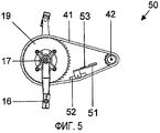
Для достижения дополнительного упрощения измерительного прибора, используемого для измерения прилагаемого усилия, предпочтительно, чтобы измерительный блок для измерения приводного усилия представлял собой рычаг, соединенный с тяговым механизмом, в частности с цепью зубчатой передачи, который немного нажимает на сторону тягового механизма и имеет измерительный датчик для измерения тягового усилия, таким образом, прилагаемого тяговым механизмом.To achieve further simplification of the measuring device used to measure the applied force, it is preferable that the measuring unit for measuring the driving force is a lever connected to the traction mechanism, in particular to the gear chain, which slightly presses on the side of the traction mechanism and has a measuring sensor for measuring traction, thus applied by the traction mechanism.
Предпочтительно, может применяться система оценки для приема сигналов от измерительного блока относительно прилагаемого приводного усилия или относящегося к нему прилагаемого скручивающего усилия и для вычисления развития во времени приводного усилия или скручивающего усилия, а также переменных, выводимых из величин на основе сигналов, выданных измерительным устройством, и непрерывного их отображения. Устройство оценки, кроме того, может принимать от измерительного прибора сигналы относительно моментов времени изменения нагрузки и распределять вычисленные переменные поочередно для правой или левой конечностей тренирующегося человека в зависимости от чередования нагрузки, представляемого измерительным оборудованием. Выходные данные относительно переменных, вычисленных таким образом, могут, в этом случае, распределяться относительно правой и левой конечностей на основе сигнала измерительного прибора относительно моментов времени изменения нагрузки. Несложное определение и автоматизированный вывод данных относительно усилия при тренировке, распределенных для левой/правой сторон, достигаются благодаря этому дальнейшему усовершенствованию.Preferably, an evaluation system can be used to receive signals from the measuring unit with respect to the applied driving force or related applied torsional force and to calculate the development of the driving force or torsional force over time, as well as variables derived from the values based on the signals provided by the measuring device, and their continuous display. The evaluation device, in addition, can receive signals from the measuring device relative to the moments of time of the load change and distribute the calculated variables in turn for the right or left limbs of the training person, depending on the alternation of the load represented by the measuring equipment. The output regarding the variables calculated in this way can, in this case, be distributed relative to the right and left limbs based on the signal of the measuring device with respect to the moments of time of the load change. A simple definition and automated output of data regarding training effort distributed to the left / right sides is achieved through this further improvement.
Кроме того, желательно, чтобы зависимое от скорости сопротивление, которое тренирующийся человек должен преодолевать на тренажерном устройстве, соответствующем изобретению, было насколько возможно приближено к естественному, то есть соответствовало сопротивлению дорожного велосипеда. С этой целью, предпочтительно, чтобы маховик имел устройство, которое затормаживается сопротивлением воздуха и соединено с электромагнитным тормозом. Устройство, затормаживаемое сопротивлением воздуха, может быть лопастным колесом, соединенным с маховиком с возможностью вращения с блокировкой. Кроме того, лопастное колесо может иметь множество лопастей, выровненных параллельно оси вращения.In addition, it is desirable that the speed-dependent resistance that the training person must overcome on the training device according to the invention be as close to natural as possible, i.e. correspond to the resistance of a road bike. For this purpose, it is preferable that the flywheel has a device that is braked by air resistance and connected to an electromagnetic brake. The device braked by air resistance may be a paddle wheel connected to the flywheel with the possibility of rotation with blocking. In addition, the impeller may have many blades aligned parallel to the axis of rotation.
Для получения возможности дополнительного задания эффекта сопротивления воздуха, согласно потребности, предпочтительно, чтобы устройство, затормаживаемое сопротивлением воздуха, располагалось в кожухе, который имеет средство для задания величины воздушного потока, вызываемого движением маховика. Например, кожух может иметь отверстия, размер и воздухопроницаемость которых могут быть заданы, и посредством которых может быть задан воздушный поток, проходящий через кожух.To be able to additionally set the effect of air resistance, according to need, it is preferable that the device braked by air resistance is located in the casing, which has means for setting the magnitude of the air flow caused by the movement of the flywheel. For example, the casing may have openings the size and breathability of which can be specified and by which the air flow passing through the casing can be set.
Далее изобретение будет описано более подробно на основе не ограничивающего примерного варианта его осуществления, который показан на прилагаемых чертежах. На чертежах:The invention will now be described in more detail on the basis of a non-limiting exemplary embodiment, which is shown in the accompanying drawings. In the drawings:
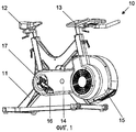
фиг.1 - вид в перспективе (спереди справа) тренажерного устройства согласно примерному варианту осуществления изобретения;figure 1 is a perspective view (front right) of a training device according to an exemplary embodiment of the invention;
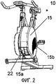
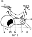
фиг.2 и 3 - тренажер в другом виде под углом и в виде сбоку слева;figure 2 and 3 - the simulator in another form at an angle and in a side view to the left;
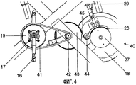
фиг.4 - вид зубчатой передачи тренажерного устройства более подробно (вид сбоку справа без кожуха);4 is a view of the gear train of the training device in more detail (side view on the right without a casing);
фиг.5 - вид детали, изображенной на фиг.4, показывающей измерение силы на цепи зубчатой передачи;5 is a view of the part shown in figure 4, showing the measurement of force on the gear chain;
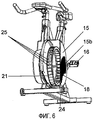
фиг.6 - вид сечения колесного барабана тренажерного устройства;6 is a sectional view of a wheel drum of a training device;
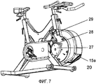
фиг.7 - вид тренажерного устройства с разомкнутым магнитным тормозом;7 is a view of a training device with an open magnetic brake;
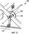
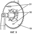
фиг.8 и 9 - детальные виды с левой стороны района расположения педалей с частично снятым кожухом таким образом, чтобы датчики для измерения положения педали были видны, при этом показанные на фиг.7 опорная штанга и осевая втулка опущены;Figs. 8 and 9 are detailed views on the left side of the area of the pedals with the cover partially removed so that the sensors for measuring the position of the pedal are visible, while the support rod and axial sleeve shown in Fig. 7 are omitted;
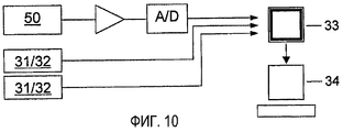
фиг.10 - блок-схема оценки сигнала и данных;figure 10 is a block diagram of the evaluation of the signal and data;
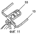
фиг.11 - вид руля тренажерного устройства с дисплеем, и11 is a view of the steering wheel of a training device with a display, and
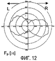
фиг.12 - пример отображения приводного усилия в зависимости от угла поворота (в полярной форме).Fig - an example of the display of the drive force depending on the angle of rotation (in polar form).
Примерный вариант осуществления изобретения, описанный далее, относится к стационарному эргометрическому велотренажеру, который показан на фиг.1-3 в различных видах. Тренажер 10 может использоваться, например, как домашний тренажер, как тренажер в тренировочном зале или может использоваться в элитном спорте или также в медицинской области.An exemplary embodiment of the invention, described below, relates to a stationary ergometric exercise bike, which is shown in figures 1-3 in various forms. The
Тренажер 10 имеет раму 11 велосипедного типа с сиденьем 12 и рулем 13, положения которых могут регулироваться, в то время как сам тренажер в ходе тренировочного цикла неподвижен. В районе расположения ног находится кожух 14, который в районе его передней части имеет защитное ограждение 15 колеса, а также пару педалей 16. Педали 16 прикреплены к оси 17 педалей известным образом и связаны через зубчатую передачу с механизмами сопротивления, которые расположены в защитном ограждении 15 колеса, как описано ниже.The
Как показано на фиг.4, зубчатая передача 40 в показанном примерном варианте осуществления изобретения представляет собой комбинацию двух тяговых приводов, а именно зубчатой передачи и ременного привода, при помощи которых достигается высокая передача движения педали 16 маховику 18. Педали 16 жестко соединены через ось 17 педалей с зубчатым колесом 19, которое приводит ведущее зубчатое колесо 42 при помощи цепи 41. Ведущее зубчатое колесо 42, в свою очередь, соединено с дисковым колесом 43, которое приводит маховик 18 при помощи ремня 45, натянутого при помощи вспомогательного колеса 44.As shown in FIG. 4, the
Показанный вариант осуществления изобретения имеет измерительную систему с точностью измерения 2% или выше. Она служит для измерения усилия, прилагаемого пользователем, и скорости вращения педалей и соединена с вычислительной системой для отображения и оценки измеренных данных.The embodiment shown has a measurement system with a measurement accuracy of 2% or higher. It serves to measure the effort exerted by the user and the speed of rotation of the pedals and is connected to a computer system for displaying and evaluating the measured data.
Измерение усилияForce measurement
Как показано на фиг.5, измерительный блок 50, предпочтительно, расположен в первом тяговом приводе для измерения усилия, которое тренирующийся человек прилагает через педальный привод к цепи 41. Когда длина педали постоянна и известна, приводное усилие может быть вычислено непосредственно с получением действующего вращающего момента (момента силы, "скручивающего усилия") и наоборот, и, в этом отношении, эквивалентных.As shown in FIG. 5, the measuring
Измерительный блок, предпочтительно, выполнен в форме коромысла, изгибающегося с измерительной растягивающейся лентой, который немного отклоняет цепь и измеряет восстанавливающую силу. Рычаг 51, прикрепленный к раме 11, опирается ее концом на ползун 52, который, например, выполнен из пластмассы. Ползун наложен на цепь 41, например, с внутренней стороны, подобно натяжителю цепи, и немного отталкивает цепь наружу. Если цепь натягивается в результате воздействия силы, прилагаемой человеком при тренировке, тангенциальная составляющая силы воздействует на пластмассовый ползун, и на ползун воздействует восстанавливающаяся сила, которая пропорциональна натяжению цепи и, следовательно, скручивающему усилию. Упругий изгиб рычага 51, вызываемый таким образом, измеряется измерительным датчиком, например лентой 53 для измерения натяжения. Сигнал от измерительного датчика оценивается с помощью электроники, как описано ниже.The measuring unit is preferably made in the form of a rocker arm bending with a measuring stretch tape that slightly deflects the chain and measures the restoring force. The
Для калибровки измерения силы к одной из педалей 16 прикрепляют груз известной величины, и вращение механически блокируют на маховике 18 или диске 27 маховика (фиг.7), например, при помощи блокирующего средства (не показано). Сила, измеренная при таких обстоятельствах, служит основанием для калибровки системы измерения усилия по сравнению с известным усилием, прилагаемым грузом.To calibrate the force measurement, a load of known magnitude is attached to one of the
Механизм сопротивленияResistance mechanism
Как показано на фиг.6, маховик 18, ведомый движением педали через зубчатую передачу 60, имеет воздушное лопастное колесо 21, которое установлено без возможности вращения по окружности лопастного колеса. Воздушное лопастное колесо 21 расположено в собственном контейнере, как части защитного ограждения 15 колеса.As shown in Fig.6, the
Как можно видеть на фиг.7, в показанном примерном варианте осуществления изобретения тормоз 20 на вихревых токах расположен на одной оси с маховиком 18, предпочтительно, напротив него. Тормоз 20 на вихревых токах является, например, магнитным тормозом, в котором металлический диск 27 маховика взаимодействует с регулируемыми (постоянными) магнитами 28 известным образом; в альтернативном варианте, также могут быть применены другие тормоза, действующие по электромагнитному принципу. В показанном примерном варианте осуществления изобретения магниты расположены на стальном кронштейне вдоль периферийной части диска 27 и направляются к диску 27 или от него с помощью установочного механизма 29. Диск 27 состоит из стали и, например, покрыт медным кольцом. Для получения возможности полностью заблокировать вращение, в диске выполнены два отверстия 27, например отверстия, в которые могут быть вставлены со стороны блокирующие штифты (не показаны), удерживаемые в кожухе или на раме.As can be seen in FIG. 7, in the exemplary embodiment shown, the
Механизмы сопротивления тренажерного устройства, соответствующего изобретению, дублируют сопротивления, которые возникают при движении на велосипеде. Сопротивления, воздействующие при езде на велосипеде, представляют собой: (a) сопротивление воздуха, (b) трение механических частей в велосипеде и (c) сопротивление качения между шинами и поверхностью дороги или сопротивление из-за наклона поверхности. Как правило, сопротивление воздуха составляет подавляющую пропорцию, часто составляющую больше 90% полного сопротивления, и возрастает в квадрате при увеличении скорости. Поэтому генерируемая мощность возрастает в кубе при увеличении скорости. Трение в велосипеде и сопротивление качению возрастают линейно при увеличении скорости, что соответствует мощности с квадратичной зависимостью от скорости.The resistance mechanisms of the training device according to the invention duplicate the resistance that occurs when driving a bicycle. Resistance when riding a bicycle are: (a) air resistance, (b) the friction of the mechanical parts in a bicycle, and (c) the rolling resistance between tires and the road surface or resistance due to the inclination of the surface. As a rule, air resistance is an overwhelming proportion, often more than 90% of the total resistance, and increases in the square with increasing speed. Therefore, the generated power increases in the cube with increasing speed. Friction in a bicycle and rolling resistance increase linearly with increasing speed, which corresponds to power with a quadratic dependence on speed.
В тренажере 10 используется комбинированная тормозная система для моделирования этих двух типов сопротивления. Он имеет две тормозные подсистемы, а именно, как уже описано, тормозной механизм, действующий при помощи торможения воздухом, в форме колеса 21 и тормоз 20, действующий по электромагнитному принципу. Таким образом, достигается реалистическое моделирование коэффициента сопротивления велосипеда, дающее ощущение движения на "нормальном" велосипеде. Эти две подсистемы могут быть настроены независимо друг от друга. Они не влияют на измерительное оборудование, описанное ниже. Комбинация двух тормозных подсистем делает возможным получение большого диапазона сопротивления, которое зависит от частоты работы педалями. Какие-либо внешние источники энергии не требуются.The
Как показано на фиг.6, воздушное лопастное колесо 21 имеет по существу цилиндрическую кольцеобразную форму. Вдоль окружности расположено множество лопастей 25, находящихся на одинаковых расстояниях между двумя удерживающими кольцами 24 по бокам, причем каждая лопасть расположена параллельно оси вращения колеса 21 и под углом, отличным от 90° к радиусу. Когда колесо 21 вращается, лопасти 25 перемещают окружающий воздух внутрь. Таким образом, воздух всасывается через боковое окно 15b и вытесняется через отверстие 15a (фиг.2), находящееся на нижней передней стороне защитного ограждения 15 колеса; следовательно, колесо 21 затормаживается получаемой циркуляцией воздуха.As shown in FIG. 6, the
В отличие от известных тренажеров с воздушным тормозом, сопротивление в показанном оборудовании может быть установлено посредством регулирования забора воздуха на стороне статора (фиг.3), а именно посредством большего или меньшего закрывания отверстия 15a при помощи створки 22 и/или регулирования бокового окна 15b относительно его воздухопроницаемости, например, по принципу жалюзи. Таким образом, тормозящее действие благодаря сопротивлению воздуха может быть установлено в пределах большого диапазона. В частности, благодаря закрыванию отверстия 15a и окна 15b, сопротивление может быть установлено на минимальную величину, близкую к нулю, таким образом, что в системе по существу остается только механическое трение.In contrast to the known simulators with an air brake, the resistance in the equipment shown can be established by adjusting the air intake on the stator side (Fig. 3), namely by closing the
Сопротивление для каждой из двух тормозных подсистем может быть установлено при помощи этих мер. В показанном примерном варианте осуществления изобретения может быть выбран эффект сопротивления от 0 до 5000 Вт.Resistance for each of the two brake subsystems can be established using these measures. In the shown exemplary embodiment of the invention, a resistance effect of 0 to 5000 watts may be selected.
Измерение скорости педалиPedal speed measurement
На фиг.8 и 9 изображено сенсорное оборудование 30 для измерения скорости педали. Два датчика 31 магнитного поля, например герконы, расположены неподвижно в непосредственной близости зубчатого колеса 19 педальной передачи. Два постоянных магнита 32 расположены в точно противоположных положениях на зубчатом колесе 19 таким образом, что в ходе вращения зубчатого колеса 19, как только каждый магнит 32 проходит мимо каждого из датчиков 31, генерируется, например, сигнальный импульс. Возникающий таким образом сигнал поступает в средство оценки и обеспечивает точное измерение количества оборотов в минуту, а также - с учетом длины кривошипа - скорости педали.On Fig and 9 shows the
Оба датчика 31 и относящиеся к ним магниты 32 соответствуют друг другу парами, и каждый из них расположен на разных радиальных расстояниях от оси (для исключения возможности активизации одного датчика на каждой стороне магнитом другого датчика). Магниты расположены в отношении их углового положения относительно датчиков, относящихся к каждому из них относительно расположения педалей 16 таким образом, что сигнальный импульс от датчика 31 выдается в каждом случае, если происходит чередование усилия от левой педали к правой или наоборот. Как можно видеть на фиг.8 и 9, в показанном положении 0° (правая педаль ориентирована перпендикулярно вверх) один магнит находится точно в положении соответствующего ему датчика, в то время как другой магнит расположен точно против соответствующего ему датчика. Это позволяет распределять измерение и разделять распределение на левую и правую ноги и оценивать силу и мощность справа/слева, прилагаемые каждой ногой, а также сравнивать усилия двух ног (баланс).Both
Благодаря распределению пары магнита и датчика таким образом, чтобы они были совмещены для обнаружения положений изменения нагрузки, может быть установлено начало измерительного цикла, который обычно состоит из последовательности дискретных точек измерения. Последовательность педалей в положениях датчика, следовательно, при чередовании нагрузки, выбрана как начало серии измерений, таким образом, что, с одной стороны, точка измерения может встречаться при изменении нагрузки (где, в частности, следует ожидать минимум прилагаемой силы у неопытных велосипедистов), и, с другой стороны, серия измерений выполняется между последовательными циклами датчика при по существу постоянной скорости; так как после изменения нагрузки угловая скорость движения педали эмпирически по существу постоянна, в отличие от этого, скорость между индивидуальными шаговыми циклами часто может изменяться. Это позволяет упростить измерительный процесс, а также улучшить надежность оценки данных, зарегистрированных относительно силы, как функции положения ноги, в частности, угла поворота.By distributing the magnet and sensor pairs so that they are aligned to detect the position of the load change, the start of the measurement cycle, which usually consists of a sequence of discrete measurement points, can be established. The sequence of pedals in the positions of the sensor, therefore, when alternating the load, is chosen as the beginning of a series of measurements, so that, on the one hand, the measuring point can occur when the load changes (where, in particular, we should expect a minimum of applied force for inexperienced cyclists), and, on the other hand, a series of measurements is performed between successive cycles of the sensor at a substantially constant speed; since after changing the load, the angular speed of the pedal is empirically essentially constant, in contrast, the speed between individual step cycles can often change. This makes it possible to simplify the measurement process, as well as to improve the reliability of evaluating data recorded with respect to force as a function of the position of the leg, in particular, the angle of rotation.
ОценкаRating
Как показано на фиг.10, сигналы датчика, выдаваемые датчиком 53 измерения силы (лентой для измерения натяжения) и датчиками 31, распределенными для измерения относительно педалей, усиливаются, переводятся в цифровую форму при помощи аналого-цифровых преобразователей и передаются в электронное средство оценки, например, дисплей 33 тренажера, расположенный на руле (фиг.11), и/или в предназначенную для этого компьютерную систему 34. В компьютерной системе 34 сигналы преобразуются в зависящем от времени процессе в приводное усилие, прилагаемое к педалям, например, со скоростью передачи данных 100 информационных точек в секунду. Кроме того, сигналы могут отображаться в режиме реального времени и/или сохраняться. Данные затем могут быть вызваны повторно и скорректированы позже. Отображение данных, предпочтительно, осуществляется относительно вращения педалей и/или на полярном дисплее, таком как показан на фиг.12.As shown in FIG. 10, the sensor signals provided by the force measuring sensor 53 (a tension measuring tape) and
На фиг.12 показан пример измеренного усилия Fp на педали (в Н; внешний круг соответствует 250 Н) при полном обороте педали, как функция угла поворота на полярной диаграмме. Показанные углы прямо соответствуют углу педали, которая перемещена в направлении по часовой стрелке, где 0° соответствуют расположению правой педали перпендикулярно вверх. Также следует указать, что, в частности, у тренированных спортсменов и спортсменок возникает синергия между двумя ногами, и чем лучше скоординированная способность калибруется для тренирующихся людей, тем круглее фигура кривой Fp.12 shows an example of the measured pedal force F p (in N; the outer circle corresponds to 250 N) at full pedal rotation as a function of the angle of rotation in the polar diagram. The angles shown directly correspond to the angle of the pedal, which is moved in a clockwise direction, where 0 ° correspond to the location of the right pedal perpendicular upward. It should also be noted that, in particular, trained athletes and sportswomen have synergy between two legs, and the better the coordinated ability is calibrated for training people, the rounder the shape of the curve F p .
В компьютерной системе 40, при помощи пригодного эргометрического программного обеспечения на экране выполняется анализ данных измерений и графическое отображение, например:In the
- вычисления и изображения момента педали,- calculations and images of the moment of the pedal,
- силы, как функции положения ноги,- forces, as a function of the position of the leg,
- количества оборотов в минуту,- the number of revolutions per minute,
- скорости (вычисленной для отвлеченной скорости велосипеда),- speed (calculated for the abstract speed of the bike),
- мощности (Вт),- power (W),
- средней мощности,- average power
- энергии (кДж посредством интегрирования),- energy (kJ through integration),
- баланса между левой и правой ногами (в %),- balance between left and right legs (in%),
- частоты сердечных сокращений (при помощи дополнительного сенсорного датчика, носимого пользователем),- heart rate (using an optional touch sensor worn by the user),
- статистического анализа.- statistical analysis.
Конечно, изобретение не ограничено описанным примерным вариантом его осуществления, а скорее распространяется на все варианты осуществления изобретения, входящие в объем формулы изобретения. В частности, тренажерное устройство, соответствующее изобретению, может иметь приводные элементы, отличные от педалей, например шаговые платформы, такие как педали лестничного типа, или пару рукояток, которые поочередно приводятся в действие. Здесь движение преобразуется известным механическим образом через зубчатую передачу во вращательное движение ведущего колеса.Of course, the invention is not limited to the described exemplary embodiment, but rather extends to all embodiments of the invention falling within the scope of the claims. In particular, the training device according to the invention may have drive elements other than pedals, for example stepping platforms, such as stair-type pedals, or a pair of handles that are alternately actuated. Here, the movement is converted in a known mechanical way through a gear transmission into the rotational movement of the drive wheel.
Claims (18)
отличающееся тем, что устройство включает в себя колесо (19), соединенное с приводом таким образом, что оно синхронно движется с ним, и измерительный прибор (30) имеет пару сенсорных устройств, которые расположены в положениях относительно колеса (19), причем сигнал генерируется, когда колесо (19) расположено в каждом из двух определенных угловых положений в движении, положения соответствуют точкам чередования нагрузки между поочередно приводимыми в действие приводными элементами.1. Stationary ergometric training device with a manual or foot drive with two alternately driven drive elements (16), preferably foot pedals, in which the drive is connected to the flywheel (18) by means of a gear transmission, as well as with a measuring unit (50) for measuring at least one of the driving force exerted by the drive and the associated torque, and a measuring device (30) for measuring the position in motion, in particular the angular position of the drive,
characterized in that the device includes a wheel (19) connected to the drive so that it moves synchronously with it, and the measuring device (30) has a pair of sensor devices that are located in positions relative to the wheel (19), and a signal is generated when the wheel (19) is located in each of two defined angular positions in motion, the positions correspond to alternating load points between alternately driven drive elements.
отличающееся тем, что устройство включает в себя колесо (19), соединенное с приводом таким образом, что оно синхронно движется с ним, и измерительный прибор (30) имеет по меньшей мере один датчик (31) и по меньшей мере один сенсорный компонент (32), расположенные в положениях друг против друга относительно колеса, каждое из упомянутых положений соответствует положению в движении при чередовании нагрузки между приводными элементами.2. A stationary ergometric training device with a manual or foot drive with two alternately driven drive elements (16), preferably foot pedals, in which the drive is connected to the flywheel (18) via a gear transmission, as well as to a measuring unit (50) for measuring at least one of the drive force exerted through the drive and the associated torque, and a measuring device (30) for detecting alternating loads between alternately driven drive elec- trons elements
characterized in that the device includes a wheel (19) connected to the drive so that it moves synchronously with it, and the measuring device (30) has at least one sensor (31) and at least one sensor component (32 ), located in positions opposite each other relative to the wheel, each of the mentioned positions corresponds to the position in motion during the alternation of the load between the drive elements.
(i) измеряют приводное усилие, приложенное посредством приводных элементов, или относящийся к нему вращающий момент;
(ii) обнаруживают моменты времени чередования нагрузки между поочередно приводимыми в действие приводными элементами; и
(iii) вычисляют и непрерывно выводят развитие во времени приводного усилия или относящегося к нему вращающего момента, а также переменных, выведенных из приводного усилия, на основе измерений, полученных на этапах (i) и (ii).15. A method for evaluating the characteristics of a person exercising on a stationary ergometric training device according to any one of claims 1-14, comprising the steps of:
(i) measure the drive force applied by the drive elements, or related torque;
(ii) detecting moments of alternating load between alternately driven drive elements; and
(iii) calculating and continuously deriving over time the development of the driving force or related torque, as well as the variables derived from the driving force, based on the measurements obtained in steps (i) and (ii).
(iv) распределяют переменные, вычисленные на этапе (iii) поочередно относительно правой или левой конечности тренирующегося человека в зависимости от моментов времени чередования нагрузки, обнаруженных на этапе (ii).16. The method of claim 15, further comprising the step of:
(iv) the variables calculated in step (iii) are distributed alternately with respect to the right or left limb of the training person, depending on the moments of load alternation detected in step (ii).
Applications Claiming Priority (5)
| Application Number | Priority Date | Filing Date | Title |
|---|---|---|---|
| ATA1364/2007 | 2007-08-30 | ||
| ATA1363/2007 | 2007-08-30 | ||
| AT13642007 | 2007-08-30 | ||
| AT0136307A AT505617B1 (en) | 2007-08-30 | 2007-08-30 | ERGOMETRIC TRAINING DEVICE |
| PCT/AT2008/000306 WO2009026604A2 (en) | 2007-08-30 | 2008-08-28 | Ergometric training device |
Publications (2)
| Publication Number | Publication Date |
|---|---|
| RU2010111912A RU2010111912A (en) | 2011-10-10 |
| RU2472557C2 true RU2472557C2 (en) | 2013-01-20 |
Family
ID=40329323
Family Applications (1)
| Application Number | Title | Priority Date | Filing Date |
|---|---|---|---|
| RU2010111912/12A RU2472557C2 (en) | 2007-08-30 | 2008-08-28 | Ergometric simulator |
Country Status (18)
| Country | Link |
|---|---|
| US (1) | US8641581B2 (en) |
| EP (2) | EP2407216B1 (en) |
| JP (1) | JP5666301B2 (en) |
| CN (1) | CN101842138B (en) |
| AT (1) | ATE496659T1 (en) |
| AU (1) | AU2008291668B2 (en) |
| BR (1) | BRPI0816102B1 (en) |
| CA (1) | CA2697297C (en) |
| DE (1) | DE502008002499D1 (en) |
| DK (2) | DK2407216T3 (en) |
| ES (2) | ES2387417T3 (en) |
| HK (1) | HK1143103A1 (en) |
| ME (1) | ME01204B (en) |
| NZ (1) | NZ583529A (en) |
| PL (2) | PL2407216T3 (en) |
| RS (2) | RS53712B1 (en) |
| RU (1) | RU2472557C2 (en) |
| WO (1) | WO2009026604A2 (en) |
Cited By (7)
| Publication number | Priority date | Publication date | Assignee | Title |
|---|---|---|---|---|
| WO2015026744A1 (en) * | 2013-08-17 | 2015-02-26 | MedHab, LLC | System and method for monitoring power applied to a bicycle |
| RU2635201C2 (en) * | 2014-11-18 | 2017-11-09 | Валентин Алексеевич Настасенко | Electricity machine with muscular drive |
| RU2720825C1 (en) * | 2019-12-11 | 2020-05-13 | Владимир Александрович Степанов | Exercise bicycle for preventing and treating prostatitis (two versions) |
| RU2754981C1 (en) * | 2020-12-16 | 2021-09-08 | Владимир Александрович Степанов | Simulator for prevention and treatment of prostatitis |
| RU2755380C1 (en) * | 2020-12-28 | 2021-09-15 | Владимир Александрович Степанов | Simulator for prevention and treatment of prostatitis |
| RU2757706C1 (en) * | 2020-12-30 | 2021-10-20 | Владимир Александрович Степанов | Trainer for prevention and treatment of prostatitis |
| RU2766389C1 (en) * | 2021-09-03 | 2022-03-15 | Владимир Александрович Степанов | Prostatitis prevention and treatment exercise machine |
Families Citing this family (46)
| Publication number | Priority date | Publication date | Assignee | Title |
|---|---|---|---|---|
| ME01204B (en) | 2007-08-30 | 2013-03-20 | Wilson John Dudley | Ergometric training device |
| SI23421A (en) * | 2010-07-07 | 2012-01-31 | Univerza V Ljubljani | Device for assessing and display of vector differences by forces, performed by a pair of hands or legs |
| CN102462926B (en) * | 2010-11-19 | 2013-11-06 | 期美科技股份有限公司 | Circulation track detection system for physical trainer and detection method thereof |
| EP2753242A4 (en) * | 2011-09-08 | 2015-01-14 | Paofit Holdings Pte Ltd | Sensor device and system for fitness equipment |
| AU2013249210B2 (en) * | 2012-04-19 | 2016-06-09 | IFIT, Inc. | Torque sensing pulleys and related methods and systems |
| US9950209B2 (en) | 2013-03-15 | 2018-04-24 | Nautilus, Inc. | Exercise machine |
| EP2969066B1 (en) | 2013-03-15 | 2017-10-04 | Nautilus, Inc. | Exercise machine |
| US9199115B2 (en) | 2013-03-15 | 2015-12-01 | Nautilus, Inc. | Exercise machine |
| CN103611265B (en) * | 2013-12-17 | 2015-09-16 | 山东英吉多健康产业有限公司 | There is the Spinning of novel transmission mode |
| TWI548438B (en) * | 2013-12-20 | 2016-09-11 | 岱宇國際股份有限公司 | Exercise device providing symmetry index |
| CN105214282B (en) * | 2014-06-10 | 2018-02-27 | 明跃国际健康科技股份有限公司 | Detect the device and method of sport dynamics information |
| US9283434B1 (en) * | 2014-09-30 | 2016-03-15 | Strength Master Fitness Tech Co., Ltd. | Method of detecting and prompting human lower limbs stepping motion |
| KR101702547B1 (en) * | 2014-12-08 | 2017-02-03 | 정재공 | Multipurpose bicycle health machine |
| JP6301858B2 (en) * | 2015-02-27 | 2018-03-28 | 臺灣輔康醫療▲器▼材股▲ふん▼有限公司Preventive Medical Health Care Co., Ltd. | Exercise equipment |
| JP2017038757A (en) * | 2015-08-19 | 2017-02-23 | セイコーエプソン株式会社 | Pedaling measurement device, pedaling measurement system, pedaling measurement method, and program |
| RU2670696C9 (en) * | 2015-09-25 | 2018-11-28 | Альберт КИ | Portable cylinder-piston equipment for physical exercises with magnets and viscous liquid, creating moisture resistance |
| GB2546113A (en) * | 2016-01-11 | 2017-07-12 | Wattbike Ip Ltd | Stationary ergometric exercise device |
| TWI598134B (en) * | 2016-04-29 | 2017-09-11 | 力山工業股份有限公司 | Resistance apparatus for exercise equipment |
| CN107349556B (en) * | 2016-05-09 | 2019-07-02 | 力山工业股份有限公司 | The resistance sensing mechanism of fitness equipment |
| IT201600083062A1 (en) * | 2016-08-05 | 2018-02-05 | Technogym Spa | Exercise equipment for cycling simulation and its method of operation. |
| EP3549646B1 (en) * | 2016-11-30 | 2023-08-16 | Leomo, Inc. | Motion capture system, motion capture program, and motion capture method |
| US10272280B2 (en) * | 2017-02-16 | 2019-04-30 | Technogym S.P.A. | Braking system for gymnastic machines and operating method thereof |
| CZ307852B6 (en) * | 2017-05-24 | 2019-06-26 | Technická univerzita v Liberci | Rehabilitation ergometer and its control |
| US10561891B2 (en) | 2017-05-26 | 2020-02-18 | Nautilus, Inc. | Exercise machine |
| CO2017005734A1 (en) * | 2017-06-09 | 2017-12-15 | Univ Autonoma De Bucaramanga | Assisted rehabilitation system |
| USD1001920S1 (en) * | 2017-08-17 | 2023-10-17 | Saris Equipment, Llc | Exercise cycle |
| USD873933S1 (en) | 2017-11-03 | 2020-01-28 | Wattbike Ip Limited | Bicycle trainer |
| US10525301B2 (en) * | 2017-12-07 | 2020-01-07 | Great Fitness Industrial Co., Ltd. | Expandable exercise system |
| JP6782722B2 (en) * | 2018-03-01 | 2020-11-11 | 臺灣輔康醫療▲器▼材股▲ふん▼有限公司Preventive Medical Health Care Co., Ltd. | Exercise equipment |
| GB201810397D0 (en) * | 2018-06-25 | 2018-08-08 | Wattbike Ip Ltd | Method and apparartus for monitoring user effectivness during operation of an exercise machine |
| CN109126025A (en) * | 2018-09-30 | 2019-01-04 | 李振平 | The double resistance systems in fitness equipment geomantic omen |
| EP3679995B1 (en) * | 2019-01-14 | 2021-07-21 | Emotion Fitness GmbH & Co. KG | Stationary exercise device |
| US11079918B2 (en) | 2019-02-22 | 2021-08-03 | Technogym S.P.A. | Adaptive audio and video channels in a group exercise class |
| US10888736B2 (en) | 2019-02-22 | 2021-01-12 | Technogym S.P.A. | Selectively adjustable resistance assemblies and methods of use for bicycles |
| US11633647B2 (en) | 2019-02-22 | 2023-04-25 | Technogym S.P.A. | Selectively adjustable resistance assemblies and methods of use for exercise machines |
| US11040247B2 (en) | 2019-02-28 | 2021-06-22 | Technogym S.P.A. | Real-time and dynamically generated graphical user interfaces for competitive events and broadcast data |
| USD909497S1 (en) * | 2019-03-20 | 2021-02-02 | Dyaco International, Inc. | Spin bike |
| CN110327587B (en) * | 2019-07-09 | 2021-05-28 | 厦门景杉网络科技有限公司 | Method for simulating route riding of exercise bicycle and exercise bicycle system |
| CN110314327B (en) * | 2019-07-11 | 2020-11-27 | 绍兴柯桥星蓝能环境科技有限公司 | Pedal exercise device |
| RU199785U1 (en) * | 2020-04-15 | 2020-09-21 | Федеральное государственное казенное военное образовательное учреждение высшего образования "Военный университет" Министерства обороны Российской Федерации | MAGNETIC FLUID BIKE |
| USD977598S1 (en) * | 2020-05-28 | 2023-02-07 | Shanghai Wenjia Industrial Co., Ltd | Spinning bike |
| RU199782U1 (en) * | 2020-06-08 | 2020-09-21 | Федеральное государственное казенное военное образовательное учреждение высшего образования "Военный университет" Министерства обороны Российской Федерации | MAGNETIC FLUID UNIVERSAL SIMULATOR |
| RU200919U1 (en) * | 2020-06-08 | 2020-11-18 | Федеральное государственное казенное военное образовательное учреждение высшего образования "Военный университет" Министерства обороны Российской Федерации | BIKE |
| CN112827120A (en) * | 2021-03-16 | 2021-05-25 | 舒华体育股份有限公司 | Motion posture detection device and method for vehicle-type fitness equipment |
| US20230025376A1 (en) * | 2021-07-14 | 2023-01-26 | Fox Factory, Inc. | Timely component movement measuring system |
| CN114618125B (en) * | 2022-02-18 | 2023-02-24 | 郑州铁路职业技术学院 | Sports man's shank strength training equipment |
Citations (4)
| Publication number | Priority date | Publication date | Assignee | Title |
|---|---|---|---|---|
| EP0323056A2 (en) * | 1987-12-29 | 1989-07-05 | Cateye Co., Ltd. | Cycle trainer having a load applying device |
| US5027303A (en) * | 1989-07-17 | 1991-06-25 | Witte Don C | Measuring apparatus for pedal-crank assembly |
| RU2081645C1 (en) * | 1993-12-27 | 1997-06-20 | Владимир Дмитриевич Болотов | Bicycle-type training apparatus |
| GB2409651A (en) * | 2004-01-02 | 2005-07-06 | Jiann-Bang Liou | Exercise device with cooling fan |
Family Cites Families (39)
| Publication number | Priority date | Publication date | Assignee | Title |
|---|---|---|---|---|
| DE2524605A1 (en) * | 1975-06-03 | 1976-12-23 | Heinz Peter Dipl Brandstetter | DEVICE FOR MEASURING MECHANICAL WORK AND POWER |
| GB1558564A (en) * | 1975-07-03 | 1980-01-03 | Lucas Industries Ltd | Electrically assisted pedal-propelled vehicles |
| JPS5685366A (en) * | 1979-12-13 | 1981-07-11 | Matsushita Electric Ind Co Ltd | Health instrument |
| JPS60171052A (en) | 1984-02-16 | 1985-09-04 | 丸石自転車株式会社 | Beauty athletic machine |
| US4589656A (en) * | 1984-11-07 | 1986-05-20 | Nautilus Sports/Medical Industries, Inc. | Aerobic exercise device for increased user comfort |
| JPS6246193A (en) | 1985-08-23 | 1987-02-28 | Mitsubishi Electric Corp | Manufacture of heat pipe |
| US4934692A (en) * | 1986-04-29 | 1990-06-19 | Robert M. Greening, Jr. | Exercise apparatus providing resistance variable during operation |
| JPH01131423A (en) | 1987-11-17 | 1989-05-24 | Agency Of Ind Science & Technol | Torque sensor for wrapping power transmission system |
| US5051638A (en) * | 1989-12-19 | 1991-09-24 | Nathan Pyles | Magnetically variable air resistance wheel for exercise devices |
| US5165278A (en) * | 1991-02-06 | 1992-11-24 | Scientific Exercise Prescription, Inc. | Cycle ergometer |
| JPH05201374A (en) | 1992-01-28 | 1993-08-10 | Tanita:Kk | Bicycle for momentum gauge |
| DE4227586A1 (en) * | 1992-08-20 | 1994-02-24 | Werner Wolfrum | Ergometer, e.g. for training sports cyclists, - measures deformations of pedals, handlebars and seat stem independently in orthogonal directions |
| US5749807A (en) | 1993-01-19 | 1998-05-12 | Nautilus Acquisition Corporation | Exercise apparatus and associated method including rheological fluid brake |
| US5354251A (en) | 1993-11-01 | 1994-10-11 | Sleamaker Robert H | Multifunction excercise machine with ergometric input-responsive resistance |
| DE9415162U1 (en) | 1994-09-19 | 1994-11-24 | Petzke Wolfgang Dipl Ing | Electronic device for determining pedaling force |
| US5611759A (en) | 1995-06-26 | 1997-03-18 | Cycle-Ops Products, Inc. | Resistance device for bicycle trainers |
| US5573481A (en) | 1995-08-22 | 1996-11-12 | Piercy; William | Foot operated therapeutic device |
| CN1176833A (en) * | 1996-04-15 | 1998-03-25 | 杨波 | Multi-functional intelligent exercising apparatus |
| DE69729202T2 (en) | 1996-07-02 | 2005-05-04 | Graber Products, Inc., Madison | ELECTRONIC EXERCISE SYSTEM |
| US6199021B1 (en) * | 1997-10-15 | 2001-03-06 | Cc Kinetics, Inc. | Method and apparatus for measuring power output of one powering a chain driven vehicle |
| JPH11313094A (en) | 1998-04-27 | 1999-11-09 | Yazaki Corp | Supervisory system of ring type network |
| US20020004439A1 (en) | 2000-02-09 | 2002-01-10 | Galbraith Richard Scott | Multi-position exercise bicycle |
| GB0006672D0 (en) * | 2000-03-21 | 2000-05-10 | Rice Michael J P | Improvements relating to controllers |
| GB2363082B (en) * | 2000-06-06 | 2004-06-02 | Clive Graham Stevens | Resistance adjusting device for an exercise device having a wheel driven by a belt |
| DE10061923A1 (en) | 2000-12-12 | 2002-06-13 | Feo Elektronik Gmbh | ergometer |
| JP3860737B2 (en) * | 2001-10-22 | 2006-12-20 | 株式会社シマノ | Bicycle rear derailleur |
| DE10221519A1 (en) | 2002-05-14 | 2003-12-04 | Gassmann Theiss Messtech | Method and device for evaluating the forces exerted on a pedal crank |
| JP4321052B2 (en) * | 2002-11-26 | 2009-08-26 | パナソニック電工株式会社 | Cycle ergometer |
| ES2410158T3 (en) | 2003-06-17 | 2013-07-01 | Spinpower B.V. | Transmission system, and procedure to measure a driving force in it |
| US7497807B2 (en) | 2003-07-15 | 2009-03-03 | Cube X Incorporated | Interactive computer simulation enhanced exercise machine |
| CN2652450Y (en) * | 2003-09-03 | 2004-11-03 | 陈朝泉 | Control display device for sports equipment |
| CN2642357Y (en) * | 2003-09-28 | 2004-09-22 | 翰阳开发股份有限公司 | Improved bicycle damper |
| US7648446B2 (en) * | 2004-06-09 | 2010-01-19 | Unisen, Inc. | System and method for electronically controlling resistance of an exercise machine |
| CN2770718Y (en) * | 2005-02-23 | 2006-04-12 | 金仪国际科技股份有限公司 | Indoor sports car structure with combined variable electromagnetic controlled speeds |
| GB0515929D0 (en) | 2005-08-03 | 2005-09-07 | Loach Andrew R | Exercise machine |
| WO2007076068A2 (en) | 2005-12-22 | 2007-07-05 | Radow Scott B | Exercise device |
| US7833135B2 (en) * | 2007-06-27 | 2010-11-16 | Scott B. Radow | Stationary exercise equipment |
| ME01204B (en) | 2007-08-30 | 2013-03-20 | Wilson John Dudley | Ergometric training device |
| US7806006B2 (en) * | 2007-11-08 | 2010-10-05 | Grand Valley State University | Bicycle torque measuring system |
-
2008
- 2008-08-28 ME MEP-2011-74A patent/ME01204B/en unknown
- 2008-08-28 DK DK11000568.3T patent/DK2407216T3/en active
- 2008-08-28 ES ES08782834T patent/ES2387417T3/en active Active
- 2008-08-28 DE DE502008002499T patent/DE502008002499D1/en active Active
- 2008-08-28 US US12/675,150 patent/US8641581B2/en active Active
- 2008-08-28 EP EP11000568.3A patent/EP2407216B1/en active Active
- 2008-08-28 PL PL11000568T patent/PL2407216T3/en unknown
- 2008-08-28 DK DK08782834.9T patent/DK2183034T3/en active
- 2008-08-28 BR BRPI0816102-0A patent/BRPI0816102B1/en active Search and Examination
- 2008-08-28 CN CN2008801150583A patent/CN101842138B/en active Active
- 2008-08-28 WO PCT/AT2008/000306 patent/WO2009026604A2/en active Application Filing
- 2008-08-28 RU RU2010111912/12A patent/RU2472557C2/en active
- 2008-08-28 EP EP08782834A patent/EP2183034B1/en active Active
- 2008-08-28 NZ NZ583529A patent/NZ583529A/en unknown
- 2008-08-28 JP JP2010522125A patent/JP5666301B2/en active Active
- 2008-08-28 RS RS20140671A patent/RS53712B1/en unknown
- 2008-08-28 PL PL08782834T patent/PL2183034T3/en unknown
- 2008-08-28 CA CA2697297A patent/CA2697297C/en active Active
- 2008-08-28 AT AT08782834T patent/ATE496659T1/en active
- 2008-08-28 RS RS20110175A patent/RS51930B/en unknown
- 2008-08-28 AU AU2008291668A patent/AU2008291668B2/en active Active
- 2008-08-28 ES ES11000568.3T patent/ES2525568T3/en active Active
-
2010
- 2010-10-13 HK HK10109679.7A patent/HK1143103A1/en unknown
Patent Citations (4)
| Publication number | Priority date | Publication date | Assignee | Title |
|---|---|---|---|---|
| EP0323056A2 (en) * | 1987-12-29 | 1989-07-05 | Cateye Co., Ltd. | Cycle trainer having a load applying device |
| US5027303A (en) * | 1989-07-17 | 1991-06-25 | Witte Don C | Measuring apparatus for pedal-crank assembly |
| RU2081645C1 (en) * | 1993-12-27 | 1997-06-20 | Владимир Дмитриевич Болотов | Bicycle-type training apparatus |
| GB2409651A (en) * | 2004-01-02 | 2005-07-06 | Jiann-Bang Liou | Exercise device with cooling fan |
Cited By (7)
| Publication number | Priority date | Publication date | Assignee | Title |
|---|---|---|---|---|
| WO2015026744A1 (en) * | 2013-08-17 | 2015-02-26 | MedHab, LLC | System and method for monitoring power applied to a bicycle |
| RU2635201C2 (en) * | 2014-11-18 | 2017-11-09 | Валентин Алексеевич Настасенко | Electricity machine with muscular drive |
| RU2720825C1 (en) * | 2019-12-11 | 2020-05-13 | Владимир Александрович Степанов | Exercise bicycle for preventing and treating prostatitis (two versions) |
| RU2754981C1 (en) * | 2020-12-16 | 2021-09-08 | Владимир Александрович Степанов | Simulator for prevention and treatment of prostatitis |
| RU2755380C1 (en) * | 2020-12-28 | 2021-09-15 | Владимир Александрович Степанов | Simulator for prevention and treatment of prostatitis |
| RU2757706C1 (en) * | 2020-12-30 | 2021-10-20 | Владимир Александрович Степанов | Trainer for prevention and treatment of prostatitis |
| RU2766389C1 (en) * | 2021-09-03 | 2022-03-15 | Владимир Александрович Степанов | Prostatitis prevention and treatment exercise machine |
Also Published As
| Publication number | Publication date |
|---|---|
| JP5666301B2 (en) | 2015-02-12 |
| PL2407216T3 (en) | 2015-03-31 |
| CA2697297C (en) | 2014-12-16 |
| AU2008291668B2 (en) | 2013-12-19 |
| EP2183034A2 (en) | 2010-05-12 |
| CN101842138A (en) | 2010-09-22 |
| PL2183034T3 (en) | 2011-08-31 |
| RU2010111912A (en) | 2011-10-10 |
| ATE496659T1 (en) | 2011-02-15 |
| JP2010536508A (en) | 2010-12-02 |
| HK1143103A1 (en) | 2010-12-24 |
| AU2008291668A1 (en) | 2009-03-05 |
| ES2525568T3 (en) | 2014-12-26 |
| EP2407216A2 (en) | 2012-01-18 |
| EP2407216A3 (en) | 2013-01-16 |
| US8641581B2 (en) | 2014-02-04 |
| CN101842138B (en) | 2012-04-11 |
| ES2387417T3 (en) | 2012-09-21 |
| BRPI0816102A2 (en) | 2015-03-03 |
| DK2407216T3 (en) | 2014-12-01 |
| RS53712B1 (en) | 2015-04-30 |
| EP2183034B1 (en) | 2011-01-26 |
| EP2407216B1 (en) | 2014-09-24 |
| ME01204B (en) | 2013-03-20 |
| BRPI0816102B1 (en) | 2019-09-24 |
| WO2009026604A3 (en) | 2009-04-23 |
| DK2183034T3 (en) | 2011-05-23 |
| WO2009026604A2 (en) | 2009-03-05 |
| CA2697297A1 (en) | 2009-03-05 |
| NZ583529A (en) | 2012-08-31 |
| US20110111923A1 (en) | 2011-05-12 |
| DE502008002499D1 (en) | 2011-03-10 |
| RS51930B (en) | 2012-02-29 |
Similar Documents
| Publication | Publication Date | Title |
|---|---|---|
| RU2472557C2 (en) | Ergometric simulator | |
| US7311640B2 (en) | System and method for verifying the calibration of an exercise apparatus | |
| US7727125B2 (en) | Exercise machine and method for use in training selected muscle groups | |
| US8360935B2 (en) | Method, a computer program, and device for controlling a movable resistance element in a training device | |
| US5292293A (en) | Programmable physical exercise apparatus with inertia | |
| US20080096725A1 (en) | Performance monitoring & display system for exercise bike | |
| JP2010536508A5 (en) | ||
| EP2886167A1 (en) | Exercise device providing symmetry index | |
| US8162803B2 (en) | Magnetic resistance trainer power measurement | |
| JP7436398B2 (en) | Method and apparatus for monitoring user effectiveness during exercise machine operation | |
| KR101623575B1 (en) | Muscle exercise and measurement system capable of liner motion and rotational motion | |
| TWI568476B (en) | Apparatus and method for detecting sports biomechanical information | |
| CN111273051B (en) | Method for measuring pedaling frequency on riding platform | |
| US20220080244A1 (en) | Stationary exercise device | |
| JPH06229856A (en) | Measuring instrument for bicycle pedaling force | |
| Van Praagh | Short-Term Power Output in 9-Year-Old Children: Typical Error Between Ergometers | |
| DE202005012008U1 (en) | Exercise bicycle power measurement system uses electronic sensor to measure tension in strap holding calliper brake |
Legal Events
| Date | Code | Title | Description |
|---|---|---|---|
| PC41 | Official registration of the transfer of exclusive right |
Effective date: 20200924 |