RU2467693C2 - X-ray diagnostic apparatus - Google Patents
X-ray diagnostic apparatus Download PDFInfo
- Publication number
- RU2467693C2 RU2467693C2 RU2010137904/14A RU2010137904A RU2467693C2 RU 2467693 C2 RU2467693 C2 RU 2467693C2 RU 2010137904/14 A RU2010137904/14 A RU 2010137904/14A RU 2010137904 A RU2010137904 A RU 2010137904A RU 2467693 C2 RU2467693 C2 RU 2467693C2
- Authority
- RU
- Russia
- Prior art keywords
- ray
- drive
- fastener
- fastening means
- steady state
- Prior art date
Links
- 238000004846 x-ray emission Methods 0.000 claims description 15
- 230000005855 radiation Effects 0.000 claims description 11
- 230000000694 effects Effects 0.000 abstract description 2
- 239000003814 drug Substances 0.000 abstract 1
- 239000000126 substance Substances 0.000 abstract 1
- 238000012545 processing Methods 0.000 description 10
- 230000001133 acceleration Effects 0.000 description 8
- 238000000034 method Methods 0.000 description 6
- 239000002872 contrast media Substances 0.000 description 5
- 238000002594 fluoroscopy Methods 0.000 description 5
- 238000001514 detection method Methods 0.000 description 4
- 238000001802 infusion Methods 0.000 description 3
- 238000002601 radiography Methods 0.000 description 2
- 206010044565 Tremor Diseases 0.000 description 1
- 230000003213 activating effect Effects 0.000 description 1
- 238000002583 angiography Methods 0.000 description 1
- 230000015572 biosynthetic process Effects 0.000 description 1
- 238000013479 data entry Methods 0.000 description 1
- 238000013461 design Methods 0.000 description 1
- 238000010438 heat treatment Methods 0.000 description 1
- 238000003384 imaging method Methods 0.000 description 1
- 238000001990 intravenous administration Methods 0.000 description 1
- 238000009304 pastoral farming Methods 0.000 description 1
- 230000010363 phase shift Effects 0.000 description 1
- 238000001454 recorded image Methods 0.000 description 1
Images


Classifications
-
- A—HUMAN NECESSITIES
- A61—MEDICAL OR VETERINARY SCIENCE; HYGIENE
- A61B—DIAGNOSIS; SURGERY; IDENTIFICATION
- A61B6/00—Apparatus or devices for radiation diagnosis; Apparatus or devices for radiation diagnosis combined with radiation therapy equipment
- A61B6/44—Constructional features of apparatus for radiation diagnosis
- A61B6/4429—Constructional features of apparatus for radiation diagnosis related to the mounting of source units and detector units
- A61B6/4435—Constructional features of apparatus for radiation diagnosis related to the mounting of source units and detector units the source unit and the detector unit being coupled by a rigid structure
- A61B6/4441—Constructional features of apparatus for radiation diagnosis related to the mounting of source units and detector units the source unit and the detector unit being coupled by a rigid structure the rigid structure being a C-arm or U-arm
-
- A—HUMAN NECESSITIES
- A61—MEDICAL OR VETERINARY SCIENCE; HYGIENE
- A61B—DIAGNOSIS; SURGERY; IDENTIFICATION
- A61B6/00—Apparatus or devices for radiation diagnosis; Apparatus or devices for radiation diagnosis combined with radiation therapy equipment
- A61B6/44—Constructional features of apparatus for radiation diagnosis
- A61B6/4476—Constructional features of apparatus for radiation diagnosis related to motor-assisted motion of the source unit
-
- A—HUMAN NECESSITIES
- A61—MEDICAL OR VETERINARY SCIENCE; HYGIENE
- A61B—DIAGNOSIS; SURGERY; IDENTIFICATION
- A61B6/00—Apparatus or devices for radiation diagnosis; Apparatus or devices for radiation diagnosis combined with radiation therapy equipment
- A61B6/48—Diagnostic techniques
- A61B6/481—Diagnostic techniques involving the use of contrast agents
-
- A—HUMAN NECESSITIES
- A61—MEDICAL OR VETERINARY SCIENCE; HYGIENE
- A61B—DIAGNOSIS; SURGERY; IDENTIFICATION
- A61B6/00—Apparatus or devices for radiation diagnosis; Apparatus or devices for radiation diagnosis combined with radiation therapy equipment
- A61B6/50—Apparatus or devices for radiation diagnosis; Apparatus or devices for radiation diagnosis combined with radiation therapy equipment specially adapted for specific body parts; specially adapted for specific clinical applications
- A61B6/504—Apparatus or devices for radiation diagnosis; Apparatus or devices for radiation diagnosis combined with radiation therapy equipment specially adapted for specific body parts; specially adapted for specific clinical applications for diagnosis of blood vessels, e.g. by angiography
-
- A—HUMAN NECESSITIES
- A61—MEDICAL OR VETERINARY SCIENCE; HYGIENE
- A61B—DIAGNOSIS; SURGERY; IDENTIFICATION
- A61B6/00—Apparatus or devices for radiation diagnosis; Apparatus or devices for radiation diagnosis combined with radiation therapy equipment
- A61B6/44—Constructional features of apparatus for radiation diagnosis
- A61B6/4429—Constructional features of apparatus for radiation diagnosis related to the mounting of source units and detector units
- A61B6/4464—Constructional features of apparatus for radiation diagnosis related to the mounting of source units and detector units the source unit or the detector unit being mounted to ceiling
Landscapes
- Health & Medical Sciences (AREA)
- Life Sciences & Earth Sciences (AREA)
- Medical Informatics (AREA)
- Engineering & Computer Science (AREA)
- Nuclear Medicine, Radiotherapy & Molecular Imaging (AREA)
- Surgery (AREA)
- Veterinary Medicine (AREA)
- Biophysics (AREA)
- High Energy & Nuclear Physics (AREA)
- Public Health (AREA)
- General Health & Medical Sciences (AREA)
- Optics & Photonics (AREA)
- Pathology (AREA)
- Radiology & Medical Imaging (AREA)
- Biomedical Technology (AREA)
- Heart & Thoracic Surgery (AREA)
- Molecular Biology (AREA)
- Physics & Mathematics (AREA)
- Animal Behavior & Ethology (AREA)
- Vascular Medicine (AREA)
- Dentistry (AREA)
- Oral & Maxillofacial Surgery (AREA)
- Apparatus For Radiation Diagnosis (AREA)
Abstract
Description
Область техники, к которой относится изобретениеFIELD OF THE INVENTION
Изобретение относится к рентгеновскому диагностическому устройству, используемому для получения изображений, и в частности к способу, при котором собираются динамические изображения, когда средство излучения рентгеновских лучей и средство регистрации рентгеновских лучей, расположенные друг против друга, совершают движение (прецессию) по круговой или эллиптической орбите, причем орбиты расположены в различных, но параллельных друг другу плоскостях.The invention relates to an X-ray diagnostic device used to obtain images, and in particular, to a method in which dynamic images are collected when an X-ray emission means and X-ray registration means located opposite each other move (precession) in a circular or elliptical orbit , and the orbits are located in different but parallel to each other planes.
Уровень техникиState of the art
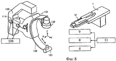
Как видно из фиг.8, рентгеновское диагностическое устройство для визуализации органов кровообращения включает в себя следующие компоненты: С-образную скобу 103, которая удерживает средство 101 излучения рентгеновских лучей и средство 102 регистрации рентгеновского изображения, расположенные друг против друга; средство 104 крепления, которое удерживает С-образную скобу 103 так, чтобы она могла плавно поворачиваться; средство 105 крепления, которое удерживает средство 104 крепления так, чтобы оно могло поворачиваться вокруг оси Y (горизонтальной оси, перпендикулярной оси поворота, вокруг которой плавно поворачивается С-образная скоба); приводное средство 113 поворота, которое плавно поворачивает С-образную скобу 103; приводное средство 114 поворота, которое поворачивает средство 104 крепления; и средство 106 управления приводом, управляющее приводными средствами 113 и 114 поворота.As can be seen from Fig. 8, an X-ray diagnostic device for visualizing the circulatory system includes the following components: a C-
При использовании вышеописанного рентгеновского диагностического устройства известный способ получения трехмерных динамических изображений заключается в том, что поворачивают С-образную скобу 103 с угловой скоростью a·sin(t) и поворачивают средство 104 крепления с угловой скоростью b·cos(t), при этом средство 101 излучения рентгеновских лучей и средство 102 регистрации рентгеновского изображения осуществляют так называемое прецессионное перемещение по соответствующим круговой или эллиптической орбитам, расположенным в плоскостях, параллельных друг другу (см., к примеру, ссылку 1 на патент).Using the above-described X-ray diagnostic device, a known method for obtaining three-dimensional dynamic images is that the C-
Ссылка 1 на патент: патент №3500778
Раскрытие изобретенияDisclosure of invention
Задачи, решаемые настоящим изобретениемTasks Solved by the Present Invention
Хотя в известном рентгеновском диагностическом устройстве соответствующие средства перемещаются в установившемся режиме по круговой или эллиптической орбитам, при этом не рассмотрено перемещение данных средств до установившегося режима.Although in the known X-ray diagnostic device, the corresponding means move in a steady state in circular or elliptical orbits, it is not considered the movement of these means to a steady state.
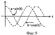
На фиг.9 изображен график угловой скорости поворота С-образной скобы 103 и средства А крепления, которые входят в состав рентгеновского диагностического устройства, соответствующего известному уровню техники. По горизонтальной оси отложено время t, а по вертикальной - угловая скорость. Угловые скорости поворота С-образной скобы 103 и средства А крепления являются тригонометрическими функциями со сдвигом по фазе, равном π/2. Это значит, что их угловые скорости никогда не равны 0 одновременно, когда достигнут установившийся режим. С-образная скоба 103 и средство 104 крепления удерживают тяжелый предмет, к примеру средство 101 излучения рентгеновских лучей или средство 102 регистрации рентгеновского изображения, поэтому они не могут быть ускорены мгновенно. При этом если они ускорятся быстро, вся система будет вибрировать. Такие вибрации могут доставить дискомфорт пациенту; кроме того, вибрации, возникшие при переходе системы в установившийся режим, могут сохраняться и после достижения установившегося режима, в результате непрерывно регистрируемые изображения будут дрожать.Figure 9 shows a graph of the angular velocity of rotation of the C-
Кроме того, пространство вокруг рентгеновского диагностического устройства занято дополнительными устройствами, к примеру диагностическим столом, на котором расположен пациент, устройствами для введения контрастного вещества и стойкой для капельного внутривенного вливания. Если компоненты рентгеновского устройства перемещаются за пределами круговой орбиты, соответствующей установившемуся режиму, то они могут задеть данные дополнительные устройства, пациента или оператора, что может быть опасно.In addition, the space around the X-ray diagnostic device is occupied by additional devices, for example, a diagnostic table on which the patient is located, devices for administering a contrast medium and a stand for drip intravenous infusion. If the components of the X-ray device move outside the circular orbit corresponding to the steady state, then they can touch these additional devices, the patient or the operator, which can be dangerous.
Желательно, чтобы перед прецессией соответствующих средств можно было наблюдать изображение из одной точки прецессионной орбиты и подтвердить его с помощью рентгеноскопии. То есть желательно, чтобы при задании позиции начала прохода по прецессионной орбите угол, под которым будет выполняться рентгенография, подтверждался бы рентгеноскопией.It is desirable that before the precession of the appropriate means it was possible to observe the image from one point of the precession orbit and confirm it using fluoroscopy. That is, it is desirable that when setting the position of the beginning of the passage in the precession orbit, the angle at which the x-ray will be performed, would be confirmed by fluoroscopy.
Задачей настоящего изобретения является решение вышеописанных проблем и обеспечение безопасной и быстрой прецессии.An object of the present invention is to solve the above problems and provide a safe and quick precession.
Способы решения проблемWays to solve problems
Для решения вышеописанных задач настоящее изобретение должно включать в себя следующие компоненты: средство излучения рентгеновских лучей; средство регистрации рентгеновского изображения; первое средство крепления для удержания средства излучения рентгеновских лучей и средства регистрации рентгеновского изображения так, чтобы они были расположены напротив друг друга; второе средство крепления для удержания первого средства крепления с возможностью поворота вокруг первой оси; первое приводное средство для поворота первого средства крепления; третье средство крепления для удержания второго средства крепления с возможностью поворота вокруг второй оси, перпендикулярной первой оси; второе приводное средство для поворота второго средства крепления; средство управления приводом для регулирования скорости вращения первого приводного средства и второго приводного средства, при этом средство управления приводом управляет первым и вторым приводными средствами так, чтобы:To solve the above problems, the present invention should include the following components: means for emitting x-rays; x-ray image recording means; first fixing means for holding the X-ray emission means and the X-ray image recording means so that they are located opposite each other; second fastening means for holding the first fastening means rotatably around the first axis; first drive means for rotating the first fastening means; third fastening means for holding the second fastening means rotatably about a second axis perpendicular to the first axis; second drive means for rotating the second fastening means; drive control means for controlling a rotation speed of the first drive means and the second drive means, wherein the drive control means controls the first and second drive means so that:
(A) в установившемся режиме первое средство крепления или второе средство крепления поворачивалось с угловой скоростью a·sin(t), а другое средство крепления поворачивалось с угловой скоростью b·cos(t), так чтобы средство излучения рентгеновских лучей и средство регистрации рентгеновских лучей осуществляли прецессионное движение по круговой или эллиптической орбите, где а и b - максимальная угловая скорость соответствующего средства крепления в установившемся режиме, t - время; и(A) in steady state, the first fastener or second fastener is rotated with an angular velocity a · sin (t), and the other fastener is rotated with an angular speed b · cos (t) so that the X-ray emission means and the X-ray detection means precessional movement was carried out in a circular or elliptical orbit, where a and b are the maximum angular velocity of the corresponding fastening means in the steady state, t is the time; and
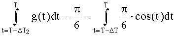
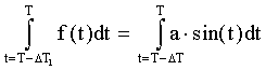
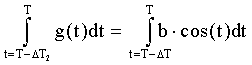
(B) одно из средств крепления находится в периоде запуска в течение времени ΔT1, от положения с исходным углом φ1 и с угловой скоростью f(t), а другое средство крепления находится в периоде запуска в течение времени ΔT2, от положения с исходным углом φ2 и с угловой скоростью g(t), при этом при условии, что установившийся режим достигается в момент времени Т, выполняются все нижеприведенные уравнения, где параметр ΔT - длительность поворота из положения с углом φ1, φ2 до положения с углом, при котором достигается установившийся режим, при повороте с угловой скоростью a·sin(t) и b·cos(t) соответственно:(B) one of the fasteners is in the start-up period for the time ΔT 1 , from the position with the initial angle φ 1 and with the angular velocity f (t), and the other fastener is in the start-up period for the time ΔT 2 , from the position the initial angle φ 2 and with the angular velocity g (t), provided that the steady state is reached at time T, all the equations below are satisfied, where the parameter ΔT is the duration of the rotation from a position with angle φ 1 , φ 2 to position c angle at which steady state is reached when turning from angular velocity a · sin (t) and b · cos (t), respectively:


f(T)=а·sin(T), f(T-ΔT1)=0f (T) = a sin (T), f (T-ΔT 1 ) = 0
g(t)=b·cos(t), G(T-ΔT2)=0g (t) = b cos (t), G (T-ΔT 2 ) = 0
![]()
![]()
![]()
![]()
φ1=-a·cos(T-ΔT)φ 1 = -a cos (T-ΔT)
φ2=b·sin(T-ΔT)φ 2 = b sin (T-ΔT)
Уравнение 2
Принцип действияOperating principle
Ниже указан технический смысл соотношений уравнения 2.Below is the technical meaning of the relations of
(1) Технический смысл значений интегралов от f(t) и g(t)(1) The technical meaning of the values of the integrals of f (t) and g (t)
Значение интеграла от f(t) соответствует углу, на который поворачивается одно из вышеуказанных средств крепления за время его движения от t=T-ΔT1 до Т. Точно так же значение интеграла от g(t) соответствует углу, на который поворачивается другое из вышеуказанных средств крепления за время его движения от t=Т-ΔТ2 до Т.The value of the integral of f (t) corresponds to the angle at which one of the above fastening means rotates during its movement from t = T-ΔT 1 to T. In the same way, the value of the integral of g (t) corresponds to the angle at which the other of the above fastening means during its movement from t = T-ΔT 2 to T.
(2) Технический смысл значений интегралов от a·sin(t) и b·cos(t) и ΔТ(2) The technical meaning of the values of the integrals of a · sin (t) and b · cos (t) and ΔТ
Предполагая, что одно из вышеуказанных средств крепления находится в установившемся режиме поворота от t=Т-ΔТ до Т, значение интеграла от a·sin(t) соответствует углу, на который поворачивается данное средство крепления. Точно так же значение интеграла от b·cos(t) соответствует углу, на который поворачивается одно из средств крепления, полагая, что другое из вышеупомянутых средств крепления перемещается в позицию, соответствующую началу установившегося режима поворота, за время от t=Т-ΔТ до Т.Assuming that one of the above fastening means is in the steady state of rotation from t = T-ΔT to T, the value of the integral from a · sin (t) corresponds to the angle that this fastening means rotates. In the same way, the value of the integral from b · cos (t) corresponds to the angle at which one of the fastening means rotates, assuming that the other of the above fastening means moves to the position corresponding to the beginning of the steady-state rotation mode, from t = Т-ΔТ to T.
(3) Технический смысл равенства значений интегралов, упомянутых выше в (1) и (2)(3) The technical meaning of the equality of the values of the integrals mentioned above in (1) and (2)
Это аналогично использованию графиков скоростей f(t) и g(t) для соответствующих временных интервалов ΔT1 и ΔТ2 для поворота одного и другого средства крепления на угол, на который они бы повернулись одновременно и мгновенно при повороте с угловой скоростью, соответствующей установившемуся режиму, за период ΔT.This is similar to using the speed graphs f (t) and g (t) for the corresponding time intervals ΔT 1 and ΔT 2 to rotate one and the other fastening means at an angle that they would turn simultaneously and instantly when turning at an angular speed corresponding to the steady state , for the period ΔT.
(4) Технический смысл f(T-ΔT1)=0, f(T)=a·sin(T), g(T-ΔT2)=0 и g(t)=b·cos(T)(4) The technical meaning is f (T-ΔT 1 ) = 0, f (T) = a sin (T), g (T-ΔT 2 ) = 0 and g (t) = b cos (T)
Они отражают тот факт, что угловая скорость соответствующих средств в начале запуска равна 0, и угловая скорость данных средств в момент завершения запуска (t=Т) равна угловой скорости средств в установившемся режиме.They reflect the fact that the angular velocity of the corresponding means at the start of the launch is 0, and the angular velocity of these means at the time of completion of the launch (t = T) is equal to the angular velocity of the means in the steady state.
(5) Технический смысл того, что абсолютные значения производных от f(t) и g(t) меньше абсолютных значений а и b(5) The technical sense is that the absolute values of the derivatives of f (t) and g (t) are less than the absolute values of a and b
Эти условия означают, что ускорение соответствующих средств во время запуска не превышает максимального ускорения в установившемся режиме.These conditions mean that the acceleration of the corresponding means during startup does not exceed the maximum acceleration in steady state.
(6) Технический смысл φ1=-a·cos(T-ΔT) и φ2=b·sin(T-ΔT)(6) The technical meaning of φ 1 = -a · cos (T-ΔT) and φ 2 = b · sin (T-ΔT)
Эти условия означают, что угол поворота в период запуска находится на круговой или эллиптической орбите и этот угол в момент Т такой, что он находится на круговой орбите при этой угловой скорости в данный момент времени.These conditions mean that the angle of rotation during the launch period is in a circular or elliptical orbit and this angle at time T is such that it is in a circular orbit at this angular velocity at a given time.
Если выполняются все из вышеуказанных условий (1)-(6), то запуск начинается с круговой или эллиптической орбиты и ускорение соответствующих средств во время запуска не превышает максимального ускорения в установившемся режиме, при этом прецессия в установившемся режиме начинается в момент времени Т.If all of the above conditions (1) - (6) are fulfilled, then the launch starts from a circular or elliptical orbit and the acceleration of the corresponding means during the launch does not exceed the maximum acceleration in the steady state, while the precession in the steady state starts at time T.
Кроме того, настоящее изобретение характеризуется тем, что средство управления приводом управляет первым приводным средством и вторым приводным средством так, чтобы за период запуска средство излучения рентгеновских лучей и средство регистрации рентгеновских лучей перемещались бы по круговой или эллиптической орбитам, соответствующим перемещению данных средств в установившемся режиме.In addition, the present invention is characterized in that the drive control means controls the first drive means and the second drive means so that during the start-up period, the X-ray emission means and the X-ray detection means move in circular or elliptical orbits corresponding to the movement of these means in steady state .
Эффекты, достигаемые при осуществлении изобретенияEffects achieved by carrying out the invention
Из вышеописанного следует, что настоящее изобретение позволяет устранить возникновение вибрации от периода запуска до прецессии в установившемся режиме, а значит, и исключить дрожание снятых изображений и ослабить ощущение страха у пациента. Кроме того, настоящее изобретение позволяет снизить до минимума риск задевания рентгеновским диагностическим устройством близлежащих предметов, к примеру, диагностического стола, на котором расположен пациент, устройств для введения в пациента контрастного вещества, стойки для инфузии и множества других устройств, а также пациента и оператора.From the above it follows that the present invention eliminates the occurrence of vibration from the start-up period to the precession in the steady state, and hence eliminates the jitter of the captured images and reduces the patient’s fear. In addition, the present invention reduces to a minimum the risk of an X-ray diagnostic device touching nearby objects, for example, a diagnostic table on which a patient is located, devices for introducing a contrast medium into the patient, an infusion stand and many other devices, as well as the patient and the operator.
Краткое описание чертежейBrief Description of the Drawings
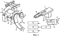
Фиг.1 - схематичный вид рентгеновского диагностического устройства, соответствующего настоящему изобретению.Figure 1 is a schematic view of an x-ray diagnostic device according to the present invention.
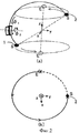
Фиг.2 - схематичный вид прецессии по настоящему изобретению.Figure 2 is a schematic view of the precession of the present invention.
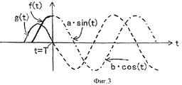
Фиг.3 - график периода запуска в соответствии с одним вариантом выполнения настоящего изобретения.Figure 3 is a graph of the launch period in accordance with one embodiment of the present invention.
Фиг.4 - графики зависимостей, показывающие соотношение между углами поворота в период запуска в соответствии с одним вариантом выполнения настоящего изобретения.4 is a dependency graph showing a relationship between rotation angles during a startup period in accordance with one embodiment of the present invention.
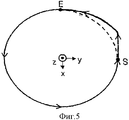
Фиг.5 - траектория перемещения средства регистрации рентгеновского излучения, соответствующая одному варианту выполнения настоящего изобретения.5 is a motion path of an X-ray detection means in accordance with one embodiment of the present invention.
Фиг.6 - графики зависимостей, показывающие соотношение между углами поворота в период запуска в соответствии с другим вариантом выполнения настоящего изобретения.6 is a graph of dependencies showing the relationship between the rotation angles during the launch period in accordance with another embodiment of the present invention.
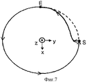
Фиг.7 - траектория перемещения средства регистрации рентгеновского излучения, соответствующая другому варианту выполнения настоящего изобретения.7 is a motion path of an X-ray detection means according to another embodiment of the present invention.
Фиг.8 - схематичный вид рентгеновского диагностического устройства, известного из уровня техники.Fig. 8 is a schematic view of an x-ray diagnostic device known in the art.
Фиг.9 - график скорости прецессии в установившемся режиме согласно известному уровню техники.Fig.9 is a graph of the speed of the precession in steady state according to the prior art.
Перечень позицийList of items
1. Рентгеновская трубка1. X-ray tube
2. Средство регистрации рентгеновского изображения2. X-ray image recording means
3. С-образная скоба (средство крепления)3. C-shaped bracket (fastener)
4. Средство крепления4. Mounting tool
5. Средство крепления5. Mounting tool
6. Контроллер привода6. Drive controller
7. Потолочные рельсы7. Ceiling rails
8. Генератор напряжения8. Voltage generator
9. Устройство для обработки изображения9. Image processing device
10. Монитор10. Monitor
11. Блок управления11. The control unit
12. Панель управления12. Control Panel
121. Устройство ввода данных121. Data entry device
122. Ручной переключатель122. Manual switch
123. Ножной переключатель123. Foot switch
124. Устройство отображения124. Display device
13. Серводвигатель13. Servo motor
14. Серводвигатель14. Servo motor
41. Ведущая шестерня41. Pinion
31. Зубчатая полоса31. Toothed strip
М. ПациентM. Patient
Т. Диагностический столT. Examination table
101. Средство излучения рентгеновских лучей101. Means of radiation of x-rays
102. Средство регистрации рентгеновского изображения102. X-ray Image Recorder
103. С-образная скоба103. C-shaped bracket
104. Средство крепления104. Mounting Tool
105. Средство крепления105. Mounting tool
113. Приводное средство поворота113. Drive turning means
114. Приводное средство поворота114. Drive turning means
106. Средство управления приводом.106. Drive control.
Лучший вариант осуществления изобретенияThe best embodiment of the invention
Далее со ссылкой на прилагаемые чертежи описаны варианты выполнения настоящего изобретения.Next, with reference to the accompanying drawings, embodiments of the present invention are described.
Вариант 1 выполнения
На фиг.1 изображен схематичный вид рентгеновского диагностического устройства, которое соответствует настоящему изобретению и включает в себя следующие компоненты: С-образную скобу 3, которая удерживает средство 1 излучения рентгеновских лучей и средство 2 регистрации рентгеновского изображения так, чтобы данные средства были расположены против друг друга; средство 4 крепления, удерживающее С-образную скобу 3 так, чтобы она могла плавно поворачиваться; средство 5 крепления, удерживающее средство 4 крепления так, чтобы средство 4 крепления могло поворачиваться вокруг оси Y; серводвигатель 13, который плавно поворачивает С-образную скобу 3; и серводвигатель 14, который поворачивает средство 4 крепления. Ось вращения серводвигателя 13 сопряжена с осью вращения ведущей шестерни 41, которая расположена на средстве 4 крепления, при этом ведущая шестерня 41 входит в зацепление с зубчатой полосой 31, которая расположена на С-образной скобе 3. При данной конфигурации вращение серводвигателя 13 приводит к повороту ведущей шестерни 41, что в свою очередь вызывает плавное перемещение С-образной скобы. Предусмотрен также контроллер 6 привода, управляющий серводвигателями 13 и 14.Figure 1 shows a schematic view of an x-ray diagnostic device, which corresponds to the present invention and includes the following components: C-shaped bracket 3, which holds the
В настоящем изобретении серводвигатели 13 и 14 служат приводными средствами поворота, а контроллер 6 привода - средством управления приводом. Однако в рамках настоящего изобретения приводное средство поворота может быть не серводвигателем, а любым другим двигателем, к примеру простым двигателем постоянного тока или двигателем переменного тока, не имеющим встроенного управления с обратной связью, но способным перемещать С-образную скобу 3 или средство 4 крепления с заданной угловой скоростью. Однако при использовании серводвигателя прецессия может быть осуществлена точнее.In the present invention, the
Средство 5 крепления закреплено так, что оно может поступательно перемещаться относительно потолочных рельсов 7. Средство 5 крепления может быть закреплено не на потолочных рельсах, а расположено на полу, при этом данное средство может быть установлено на полу или потолочных рельсах с помощью других деталей. В частности, допустимо предусмотреть средство крепления, которое удерживает средство 5 крепления так, чтобы средство 5 крепления могло поворачиваться вокруг оси Z поворота, перпендикулярной осям Х и Y поворота, и закрепить средство крепления на вышеуказанных потолочных рельсах 7 или полу.The fastening means 5 is fixed so that it can translationally move relative to the ceiling rails 7. The fastening means 5 can be mounted not on the ceiling rails, but is located on the floor, and this tool can be installed on the floor or ceiling rails using other parts. In particular, it is permissible to provide a fastening means that holds the fastening means 5 so that the fastening means 5 can rotate about the pivot axis Z perpendicular to the pivot axes X and Y, and fasten the fastening means on the above ceiling rails 7 or the floor.
В то же время пациент М размещается на диагностическом столе Т, и стол Т или С-образная скоба 3 перемещаются так, чтобы изучаемая область пациента М располагалась между средством 1 излучения рентгеновских лучей и средством 2 регистрации рентгеновского изображения. Кроме того, рентгеновское диагностическое устройство включает в себя генератор 8 высокого напряжения, подающий высокое напряжение, соответствующее заданным условиям, на средство 1 излучения рентгеновских лучей, устройство 9 для обработки изображений, которое обрабатывает сигналы, поступающие от средства 2 регистрации рентгеновских изображений, и формирует изображения, и монитор 10 (не показан), который отображает формированные изображения.At the same time, the patient M is placed on the diagnostic table T, and the table T or the C-shaped bracket 3 is moved so that the study area of the patient M is located between the X-ray emission means 1 and the X-ray image recording means 2. In addition, the x-ray diagnostic device includes a
Кроме того, рентгеновское диагностическое устройство включает в себя блок 11 управления, который подает команды на контроллер 6 привода, генератор 8 высокого напряжения и устройство 9 для обработки изображений. С блоком 11 управления соединена панель 12 управления, которая включает в себя следующие компоненты: устройство 121 ввода данных, используемое, к примеру, для задания параметров изображения и рентгеновского излучения и установки С-образной скобы 3 в заданное положение; ручной переключатель 122 для начала рентгенографии; ножной переключатель 123 для выполнения рентгеноскопии; и устройство 124 для отображения различной информации, к примеру, параметров рентгеновского излучения.In addition, the x-ray diagnostic device includes a
На устройстве 121 ввода данных расположен переключатель для перемещения в исходное положение прецессии. После того как нажат переключатель, блок 11 управления подает на контроллер 6 привода команду, и С-образная скоба 3 перемещается в заранее отмеченное исходное положение прецессии. Контроллер 6 привода, на который поступила команда, подает ее на серводвигатели 13 и 14, в результате С-образная скоба перемещается в исходное положение.A switch for moving to the initial position of the precession is located on the
Оператор управляет устройством 121 ввода данных и выбирает режим прецессии в качестве параметров изображений. Затем задаются параметры рентгеновской визуализации (рентгеноскопии, рентгенографии). После этого приводятся в действие переключатели, расположенные на устройстве 121 ввода данных, для перемещения С-образной скобы в исходное положение прецессии.An operator controls the
Когда при данных условиях оператор приводит в действие ножной переключатель 123, блок 11 управления подает на генератор 8 высокого напряжения команду об излучении рентгеновских лучей. Одновременно на устройство 9 для обработки изображений подается команда об обработке сигналов, поступающих от средства регистрации рентгеновских изображений, и генерации изображений. Генератор 8 высокого напряжения подает на средство 1 излучения рентгеновских лучей высокое напряжение, которое соответствует параметрам рентгеноскопии. Средство 1 излучения рентгеновских лучей излучает рентгеновские лучи в соответствии с данным высоким напряжением. Рентгеновские лучи, проходящие через изучаемую область пациента М, поступают на средство 2 регистрации рентгеновских изображений. Затем средство 2 регистрации рентгеновских изображений формирует на выходе сигнал в соответствии с поступившим излучением. Устройство 9 для обработки изображений получает команды от блока 11 управления, обрабатывает сигналы, исходящие от средства 2 регистрации рентгеновских изображений, и генерирует изображения, которые отображаются на мониторе 10.When, under these conditions, the operator actuates the foot switch 123, the
Оператор проверяет рентгеноскопическое изображение, которое отобразилось на мониторе 10, чтобы убедиться, что изучаемая область расположена рядом с центром изображения; если необходимо провести ангиографию с введением контрастного вещества, то оператор нажимает на переключатель 122, чтобы видеть рентгеноскопические изображения, отображаемые на мониторе, по которым можно судить, что контрастное вещество достигло главной изучаемой области. После того как нажат ручной переключатель 122, блок 11 управления подает команду на контроллер 6 привода для начала прецессии.The operator checks the fluoroscopic image that is displayed on the
Управление запускомLaunch control
После того как контроллер 6 привода, управляющий серводвигателями 13 и 14, получает команду от блока 11 управления, контроллер 6 начинает запуск. Управление запуском детально проиллюстрировано на фиг 2. На фиг.2(a) изображен вид в перспективе траектории перемещения рентгеновской трубки 1 и регистратора 2 рентгеновского изображения. Фиг.2(b) соответствует изображению на фиг.2(a), если на него смотреть в направлении оси Z. В этой специальной системе координат вектор, соединяющий рентгеновскую трубку 1 с регистратором 2 рентгеновских изображений, совпадает с осью Z тогда, когда угол φ1 поворота С-образной скобы 3 равен 0 и угол φ2 поворота средства 4 крепления равен 0. Угол φ1 поворота С-образной скобы 3 принимается положительным, если поворот происходит по часовой стрелке относительно оси Х (на фигуре - направление стрелки φ1). Угол φ2 поворота средства 4 крепления принимается положительным, если поворот происходит против часовой стрелки относительно оси Y (на фигуре - направление стрелки φ2).After the
(i) Определение исходного положения S и положения Е установившегося режима(i) Determination of the initial position S and position E of the steady state
Исходное положение (S на фиг.2(а)) С-образной скобы 3 и средства 4 крепления соответствует φ0S1=-π/6 (-30 градусов) и φ0S2=0. Принимая во внимание то, что в качестве длины запуска используется расстояние, равное 1/4 полного периода перемещения в установившемся режиме, С-образная скоба 3 должна повернуться на π/6, а средство 4 крепления - на π/6 к моменту достижения положения (Е на фиг.2(а), φ0E1=0, φ0E2=π/6), соответствующей началу работы в установившемся режиме. Отношение большей оси к меньшей оси эллиптической или круговой орбиты перемещения средства 1 излучения рентгеновских лучей и 2-мерного регистратора 2 излучения, определяемое такими условиями, как исходное положение, соответствует в настоящем изобретении отношению a к b. В данном примере осуществления настоящего изобретения φ0S1=π/6 соответствует а, а φ0E2=π/6 соответствует b. То есть средство 1 излучения рентгеновских лучей и двумерный регистратор 2 излучения перемещаются по круговым орбитам.The initial position (S in Fig. 2 (a)) of the C-shaped bracket 3 and the fastening means 4 corresponds to φ0 S1 = -π / 6 (-30 degrees) and φ0 S2 = 0. Taking into account the fact that as the length of trigger uses a distance equal to 1/4 the full period of movement in the steady state, the C-arm 3 must turn to π / 6 and the holding means 4 - to π / 6 to the time of reaching the position ( E in FIG. 2 (a), φ0 E1 = 0, φ0 E2 = π / 6), corresponding to the beginning of work in the steady state. The ratio of the major axis to the minor axis of an elliptical or circular orbit of movement of the X-ray emitting means 1 and the 2-
(ii) Вычисление времени, необходимого для запуска, на основе длины запуска(ii) Calculation of the time required for the launch, based on the length of the launch
Пусть скорость С-образной скобы 3 описывается функцией f(t); если С-образная скоба 3 перемещается в течение времени ΔT1 и конечный момент равен Т, то выполняется следующее уравнение:Let the speed of the C-shaped bracket 3 be described by the function f (t); if the C-shaped bracket 3 moves during the time ΔT 1 and the final moment is equal to T, then the following equation holds:

Уравнение 4Equation 4
Кроме того, пусть функция g(t) представляет собой скорость средства (4) крепления, если средство 4 крепления перемещается в течение времени ΔT2 и конечный момент времени равен Т, то выполняется следующее уравнение:In addition, let the function g (t) be the speed of the fastening means (4), if the fastening means 4 moves during the time ΔT 2 and the end time is T, then the following equation holds:
Уравнение 5Equation 5
В соответствии с настоящим изобретением размерность t не обязательно выражается в секундах, но может быть нормированной по времени 2π для осуществления цикла перемещения в установившемся режиме. Вышеописанный параметр аналогичен использованию в качестве длины запуска расстояния, соответствующего 1/4 периода перемещения в установившемся режиме, поэтому ΔT принимает значение π/2.In accordance with the present invention, the dimension t is not necessarily expressed in seconds, but can be normalized to 2π in time to carry out a moving cycle in steady state. The above parameter is analogous to use as run-length distance corresponding to 1/4 period moving in the steady state, so ΔT takes a value π / 2.
(ii) Вычисление времени, необходимого для запуска, на основе длины запуска(ii) Calculation of the time required for the launch, based on the length of the launch
Функции f(t) и g(t) в вышеуказанных уравнениях 4 и 5 могут быть фиксированными при любых условиях или изменяемыми в зависимости от условий. В данном примере осуществления настоящего изобретения использованы функции, изображенные на фиг.3. Эти функции удовлетворяют следующему условию: изменение скорости в период запуска не превышает соответствующего максимального ускорения. Это условие позволяет устранить искажения изображений из-за вибрации системы и создать пациенту чувство безопасности.The functions f (t) and g (t) in the above equations 4 and 5 can be fixed under any conditions or change depending on the conditions. In this embodiment, the functions depicted in FIG. 3 are used. These functions satisfy the following condition: the change in speed during the start-up period does not exceed the corresponding maximum acceleration. This condition eliminates image distortion due to system vibration and creates a sense of security for the patient.

Уравнение 6
В этом случае вычисляются значения ΔT1 и ΔТ2, удовлетворяющие этим уравнениям. Контроллер 6 привода использует вычисленные значения ΔT1 и ΔТ2 в качестве основы для формирования команд скорости, подаваемых на серводвигатели 13 и 14.In this case, the values ΔT 1 and ΔT 2 are calculated that satisfy these equations. The
На фиг.4 показано соотношение между угловой скоростью и углом поворота в период запуска, когда осуществляется вышеописанное управление. На фиг.4(а) показано изменение угловой скорости при повороте С-образной скобы 3. На этой фигуре пунктирная линия отражает скорость в установившемся режиме, a f(t) - скорость в период запуска. На левом графике фиг.4(b) изображен угол поворота за период запуска в качестве значения интеграла (площадь заштрихованной области). На правом графике фиг.4(b) изображен угол, равный значению интеграла (площади заштрихованной области), когда для привода используется та же угловая скорость, что и в установившемся режиме. Функция f(t) выбирается так, чтобы площади заштрихованных областей, изображенных в левой и правой частях фиг.4(b), были равны между собой. В данном примере осуществления настоящего изобретения угловая скорость при повороте С-образной скобы 3 во время запуска та же, что и в установившемся режиме. Аналогично на фиг.4(с) и 4(d) изображены угловая скорость и угол поворота средства 4 крепления за период запуска. Функция g(t) определяется так, чтобы площади заштрихованных областей, изображенных в левой и правой частях фиг.4(d), были равны между собой. В данном примере осуществления настоящего изобретения g(t)=b/2cos(t+ΔT2).Figure 4 shows the relationship between the angular velocity and the angle of rotation during the start-up period, when the above control is carried out. Figure 4 (a) shows the change in angular velocity when turning the C-shaped bracket 3. In this figure, the dashed line represents the speed in steady state, af (t) is the speed during the start-up period. The left graph of FIG. 4 (b) shows the rotation angle for the start-up period as the integral value (area of the hatched area). The right graph of FIG. 4 (b) shows the angle equal to the value of the integral (the area of the shaded area) when the same angular velocity is used for the drive as in steady state. The function f (t) is chosen so that the areas of the hatched areas depicted in the left and right parts of Fig. 4 (b) are equal to each other. In this embodiment of the present invention, the angular velocity when turning the C-bracket 3 during startup is the same as in steady state. Similarly, FIGS. 4 (c) and 4 (d) show the angular velocity and rotation angle of the attachment means 4 during the start-up period. The function g (t) is determined so that the areas of the hatched areas depicted in the left and right parts of FIG. 4 (d) are equal to each other. In this embodiment, g (t) = b / 2cos (t + ΔT 2 ).
Позиция Е, изображенная на фиг.2, достигается в момент времени t=Т. В данном примере осуществления настоящего изобретения сначала начинает поворачиваться средство 4 крепления со скоростью g(t), а затем - и С-образная скоба 3 со скоростью f(t).Position E, depicted in figure 2, is reached at time t = T. In this embodiment, first, the fastening means 4 starts to rotate at a speed g (t), and then the C-bracket 3 at a speed f (t).
Работа в установившемся режимеSteady state operation
Одновременно с завершением запуска блок 11 управления подает на генератор 8 высокого напряжения команду об излучении рентгеновских лучей. В то же время команда подается и на устройство 9 обработки изображений для обработки сигнала, исходящего от средства 2 регистрации рентгеновских изображений, и формирования изображений. К этому времени С-образная скоба 3 уже завершила свой запуск и перемещается в установившемся режиме по орбите прецессии. Генератор 8 высокого напряжения подает на рентгеновскую трубку 1 высокое напряжение в соответствии с заданными условиями, в результате рентгеновская трубка 1 излучает рентгеновские лучи. Излученные рентгеновские лучи проходят через изучаемую область пациента М и поступают на средство 2 регистрации рентгеновских изображений, которое выдает сигналы в соответствии с характеристиками падающего излучения. Устройство 9 обработки изображений получает команды от блока 11 управления, обрабатывает сигналы, поступающие от средства 2 регистрации рентгеновских изображений, и формирует изображения, которые отображаются на мониторе 10. Кроме того, устройство 9 обработки изображений включает в себя средство 91 хранения изображений, в котором серии изображений сохраняются. Последовательность вышеописанных операций выполняется непрерывно и одновременно с прецессией в установившемся режиме, которая вызвана перемещением С-образной скобы 3 и средства 4 крепления с помощью серводвигателей 13 и 14, поэтому на мониторе 10 отображаются трехмерные динамические изображения. Что касается момента подачи команды об излучении рентгеновских лучей от блока 11 управления на генератор 8 высокого напряжения, то эта команда может подаваться не в момент завершения запуска, а перед завершением или после него. Кроме того, желательно, чтобы подавался сигнал (так называемый сигнал готовности), необходимый для прогрева рентгеновской трубки 1, когда начат запуск, поскольку излучение рентгеновских лучей может быть начато непосредственно после подачи команды об излучении рентгеновских лучей.Simultaneously with the completion of the start, the
Завершение получения изображенияFinish image acquisition
Когда оператор прекращает активацию ручного переключателя 122, блок 11 управления подает на генератор 8 высокого напряжения команду о прекращении излучения рентгеновских лучей. При этом на устройство 9 обработки изображений поступает команда о прекращении сбора изображений. Кроме того, на средство 6 управления приводом поступает команда об остановке С-образной скобы. Желательно, чтобы С-образная скоба замедлялась при остановке так же плавно, как и ускорялась при вышеописанном запуске. Однако даже если устройство вибрирует, больше не нужно уменьшать скорость так, чтобы она изменялась с тем же в общем ускорением, что и при запуске, поскольку вибрация гасится к моменту следующего запуска. К тому же для устранения чувства страха у пациента желательно, чтобы С-образная скоба останавливалась как можно быстрее. Однако в интересах безопасности, как и при запуске, желательно, регулировать скорость поворота, так чтобы рентгеновская трубка 1 или регистратор 2 рентгеновских изображений оставались в пределах круговой орбиты.When the operator stops activating the
На фиг.5 изображена орбита рентгеновской трубки в плоскости X-Y, когда выполняется вышеописанное управление. Поскольку сначала поворачивается средство 4 крепления, рентгеновская трубка 1 перемещается по траектории, которая расположена за пределами эллиптической орбиты, соответствующей перемещению трубки в установившемся режиме. При этом возникает риск задевания устройством расположенных рядом стоек дли инфузии, электрокардиографических устройств или устройств для введения контрастного вещества. Поэтому далее описан другой вариант выполнения настоящего изобретения (вариант 2), когда устройство управляется так, чтобы траектория перемещения лежала внутри круговой или эллиптической орбиты.Figure 5 shows the orbit of the x-ray tube in the X-Y plane when the above control is performed. Since the fastener 4 is first rotated, the
Вариант 2 выполнения
Поскольку конструкция контроллера 6 привода в отношении функций, отличных от функции запуска, та же, что и в первом примере осуществления настоящего изобретения, данная функция здесь не описана.Since the design of the
(ii) Вычисление времени, необходимого для запуска, на основе длины прохода(ii) Calculation of the time required to start, based on the length of the passage
Функции f(t) и g(t), приведенные в уравнениях 4 и 5, могут быть фиксированными при всех условиях или переменными в зависимости от условий. В данном примере осуществления настоящего изобретения использованы те же функции, что изображены на фиг.6. Смысл отдельных графиков, приведенных на фиг.6, соответствует смыслу графиков, приведенных на фиг.4. Соответствующие функции удовлетворяют следующим условиям. При выполнении условия, что изменение скорости в течение периода запуска не превышает соответствующих максимальных значений ускорения, сначала начинает поворачиваться С-образная скоба 3 со скоростью f(t), а затем - и средство 4 крепления со скоростью g(t). Это позволяет устранить искажения на изображениях из-за вибраций устройства (фиг.7) и создать у пациента ощущение безопасности. Кроме того, во время запуска средство 1 излучения рентгеновских лучей и двумерный регистратор 2 излучения перемещаются внутри круговой орбиты, соответствующей установившемуся режиму.The functions f (t) and g (t) given in equations 4 and 5 can be fixed under all conditions or variable depending on the conditions. In this embodiment of the present invention, the same functions are used as depicted in FIG. 6. The meaning of the individual graphs shown in Fig.6, corresponds to the meaning of the graphs shown in Fig.4. The corresponding functions satisfy the following conditions. Under the condition that the change in speed during the start-up period does not exceed the corresponding maximum acceleration values, the C-shaped bracket 3 begins to rotate at a speed f (t), and then the fastening means 4 at a speed g (t). This allows you to eliminate distortion in the images due to vibration of the device (Fig.7) and create a patient's sense of security. In addition, during start-up, the X-ray emission means 1 and the two-
На основе вычисленных значений ΔT1 и ΔТ2 контроллер 6 привода подает на серводвигатели 13 и 14 команду по скорости. На фиг.4 изображены функции f(t) и g(t), наложенные друг на друга, при этом горизонтальная ось соответствует времени t. Позиция Е, изображенная на фиг.2, достигается в момент времени t=Т. В данном примере осуществления настоящего изобретения, поскольку значение ΔТ2 изначально больше, поэтому средство 4 крепления сначала поворачивается со скоростью g(t), и за ним С-образная скоба 3 поворачивается со скоростью f(t).Based on the calculated values of ΔT 1 and ΔT 2 , the
Таким образом, в соответствии с настоящим изобретением режим работы с использованием требуемого значения ускорения достигается при использовании разных моментов начала работы для двух осей. Однако в зависимости от используемых функций f(t) и g(t) перемещение данных средств может начаться и одновременно.Thus, in accordance with the present invention, a mode of operation using the desired acceleration value is achieved by using different moments of the start of operation for two axes. However, depending on the functions f (t) and g (t) used, the movement of these funds can begin at the same time.
Claims (2)
средство излучения рентгеновских лучей;
средство регистрации рентгеновских изображений;
первое средство крепления для удержания средства излучения рентгеновских лучей и средства регистрации рентгеновского изображения напротив друг друга;
второе средство крепления для удержания первого средства крепления с возможностью его поворота вокруг первой оси;
первое приводное средство для поворота первого средства крепления;
третье средство крепления для удержания второго средства крепления с возможностью его поворота вокруг второй оси, перпендикулярной первой оси;
второе приводное средство для поворота второго средства крепления; и
средство управления приводом для регулирования скорости приводного движения первого приводного средства и второго приводного средства;
при этом средство управления приводом выполнено с возможностью управления первым приводным средством и вторым приводным средством так, чтобы выполнялись следующие условия:
(А) одно из средств крепления, первое средство крепления или второе средство крепления, поворачивается в установившемся режиме с угловой скоростью a·sin(t), а другое средство крепления поворачивается с угловой скоростью b·cos(t), так что средство излучения рентгеновских лучей и средство регистрации рентгеновского излучения осуществляют прецессию по круговой или эллиптической орбите, где а и b - максимальная угловая скорость соответствующего средства крепления в установившемся режиме, t - время; и
(В) одно из средств крепления находится в периоде запуска в течение времени ΔT1 от положения с исходным углом φ1 и с угловой скоростью f(t), а другое средство крепления находится в периоде запуска в течение времени ΔT2 от положения с исходным углом φ2 и с угловой скоростью g(t), при этом при условии, что установившийся режим достигается в момент времени Т, выполняются все нижеприведенные уравнения, где ΔT - длительность поворота из положения с углом φ1, φ2 до положения с углом, при котором достигается установившийся режим, при повороте с угловой скоростью a·sin(t) и b·cos(t) соответственно:
f(T)=а·sin(T), f(T-ΔT1)=0
g(t)=b·cos(t), g(T-ΔT2)=0
φ1=-a·cos(T-ΔT)
φ2=b·sin(T-ΔT)1. An x-ray diagnostic device comprising:
X-ray emission means;
x-ray image recording means;
first fixing means for holding the X-ray emission means and the X-ray image recording means opposite each other;
second fastening means for holding the first fastening means with the possibility of its rotation around the first axis;
first drive means for rotating the first fastening means;
third fastening means for holding the second fastening means with the possibility of its rotation around a second axis perpendicular to the first axis;
second drive means for rotating the second fastening means; and
drive control means for controlling a driving speed of the first drive means and the second drive means;
wherein the drive control means is configured to control the first drive means and the second drive means so that the following conditions are met:
(A) one of the fastening means, the first fastening means or the second fastening means, rotates in steady state with an angular velocity a · sin (t), and the other fastening means rotates with an angular velocity b · cos (t), so that the X-ray emission means rays and means for recording x-ray radiation carry out the precession in a circular or elliptical orbit, where a and b are the maximum angular velocity of the corresponding means of fastening in the steady state, t is the time; and
(B) one of the fastening means is in the start-up period during the time ΔT 1 from the position with the initial angle φ 1 and with the angular velocity f (t), and the other fastening means is in the start-up period for the time ΔT 2 from the position with the initial angle φ 2 and with an angular velocity g (t), provided that the steady state is reached at time T, all the equations below are satisfied, where ΔT is the duration of rotation from a position with an angle of φ 1 , φ 2 to a position with an angle, at which is achieved steady state when cornering with a sin sin (t) and b cos (t), respectively:
f (T) = a sin (T), f (T-ΔT 1 ) = 0
g (t) = b cos (t), g (T-ΔT 2 ) = 0
φ 1 = -a cos (T-ΔT)
φ 2 = b sin (T-ΔT)
Applications Claiming Priority (1)
| Application Number | Priority Date | Filing Date | Title |
|---|---|---|---|
| PCT/JP2008/057260 WO2009128129A1 (en) | 2008-04-14 | 2008-04-14 | X-ray diagnostic apparatus |
Publications (2)
| Publication Number | Publication Date |
|---|---|
| RU2010137904A RU2010137904A (en) | 2012-03-20 |
| RU2467693C2 true RU2467693C2 (en) | 2012-11-27 |
Family
ID=41198841
Family Applications (1)
| Application Number | Title | Priority Date | Filing Date |
|---|---|---|---|
| RU2010137904/14A RU2467693C2 (en) | 2008-04-14 | 2008-04-14 | X-ray diagnostic apparatus |
Country Status (7)
| Country | Link |
|---|---|
| US (1) | US8233585B2 (en) |
| JP (1) | JP4962617B2 (en) |
| CN (1) | CN101969851B (en) |
| BR (1) | BRPI0822403A2 (en) |
| RU (1) | RU2467693C2 (en) |
| TR (1) | TR201007504T1 (en) |
| WO (1) | WO2009128129A1 (en) |
Families Citing this family (3)
| Publication number | Priority date | Publication date | Assignee | Title |
|---|---|---|---|---|
| JP5500931B2 (en) * | 2009-09-30 | 2014-05-21 | 株式会社東芝 | X-ray diagnostic imaging equipment |
| JP5510540B2 (en) * | 2010-04-07 | 2014-06-04 | 株式会社島津製作所 | X-ray fluoroscopic equipment |
| JP5924411B2 (en) * | 2012-07-03 | 2016-05-25 | 株式会社島津製作所 | Radiography equipment |
Citations (8)
| Publication number | Priority date | Publication date | Assignee | Title |
|---|---|---|---|---|
| EP0993272A1 (en) * | 1997-07-03 | 2000-04-19 | University of Rochester | Method of and system for cone-beam tomography reconstruction |
| RU2158537C1 (en) * | 2000-05-25 | 2000-11-10 | ЗАО "МГП Абрис" | X-ray diagnostic digital apparatus and method for manufacturing x-ray diagnostic digital apparatus arch crosspiece |
| JP2001120531A (en) * | 1999-10-26 | 2001-05-08 | Shimadzu Corp | Fluoroscopic photographing apparatus |
| RU31946U1 (en) * | 2000-08-29 | 2003-09-10 | Бехтерев Алексей Владимирович | Radiographic Scanning Device |
| US20030169847A1 (en) * | 2001-11-21 | 2003-09-11 | University Of Massachusetts Medical Center | System and method for x-ray fluoroscopic imaging |
| JP2005058309A (en) * | 2003-08-08 | 2005-03-10 | Hitachi Medical Corp | Cone beam x-ray ct device and phantom used for the same |
| JP2006271722A (en) * | 2005-03-29 | 2006-10-12 | Toshiba Corp | X-rays diagnostic apparatus |
| US20080018645A1 (en) * | 2003-11-10 | 2008-01-24 | Jeff Dwyer | Anatomical visualization and measurement system |
Family Cites Families (7)
| Publication number | Priority date | Publication date | Assignee | Title |
|---|---|---|---|---|
| US3500778A (en) * | 1969-01-30 | 1970-03-17 | Gillette Co | Automatic stretch quilting machines |
| JPS62186847A (en) * | 1986-02-12 | 1987-08-15 | 株式会社東芝 | X-ray tomographic apparatus |
| JP3500778B2 (en) * | 1995-05-31 | 2004-02-23 | 株式会社島津製作所 | X-ray diagnostic equipment |
| US7042975B2 (en) * | 2002-10-25 | 2006-05-09 | Koninklijke Philips Electronics N.V. | Four-dimensional helical tomographic scanner |
| JP4777346B2 (en) * | 2004-06-28 | 2011-09-21 | コーニンクレッカ フィリップス エレクトロニクス エヌ ヴィ | Inspection device for perfusion investigation |
| DE102006041033B4 (en) * | 2006-09-01 | 2017-01-19 | Siemens Healthcare Gmbh | Method for reconstructing a three-dimensional image volume |
| DE102006045721A1 (en) * | 2006-09-27 | 2008-04-10 | Siemens Ag | Tomographic photograph production method for partially cyclically moved test subject involves utilizing data records from detector output data of different cycle phase ranges in each of at least two iteration stages |
-
2008
- 2008-04-14 RU RU2010137904/14A patent/RU2467693C2/en not_active IP Right Cessation
- 2008-04-14 US US12/867,231 patent/US8233585B2/en active Active
- 2008-04-14 TR TR2010/07504T patent/TR201007504T1/en unknown
- 2008-04-14 BR BRPI0822403-0A patent/BRPI0822403A2/en not_active IP Right Cessation
- 2008-04-14 JP JP2010508045A patent/JP4962617B2/en active Active
- 2008-04-14 WO PCT/JP2008/057260 patent/WO2009128129A1/en active Application Filing
- 2008-04-14 CN CN2008801280394A patent/CN101969851B/en active Active
Patent Citations (8)
| Publication number | Priority date | Publication date | Assignee | Title |
|---|---|---|---|---|
| EP0993272A1 (en) * | 1997-07-03 | 2000-04-19 | University of Rochester | Method of and system for cone-beam tomography reconstruction |
| JP2001120531A (en) * | 1999-10-26 | 2001-05-08 | Shimadzu Corp | Fluoroscopic photographing apparatus |
| RU2158537C1 (en) * | 2000-05-25 | 2000-11-10 | ЗАО "МГП Абрис" | X-ray diagnostic digital apparatus and method for manufacturing x-ray diagnostic digital apparatus arch crosspiece |
| RU31946U1 (en) * | 2000-08-29 | 2003-09-10 | Бехтерев Алексей Владимирович | Radiographic Scanning Device |
| US20030169847A1 (en) * | 2001-11-21 | 2003-09-11 | University Of Massachusetts Medical Center | System and method for x-ray fluoroscopic imaging |
| JP2005058309A (en) * | 2003-08-08 | 2005-03-10 | Hitachi Medical Corp | Cone beam x-ray ct device and phantom used for the same |
| US20080018645A1 (en) * | 2003-11-10 | 2008-01-24 | Jeff Dwyer | Anatomical visualization and measurement system |
| JP2006271722A (en) * | 2005-03-29 | 2006-10-12 | Toshiba Corp | X-rays diagnostic apparatus |
Also Published As
| Publication number | Publication date |
|---|---|
| BRPI0822403A2 (en) | 2015-06-16 |
| WO2009128129A1 (en) | 2009-10-22 |
| JP4962617B2 (en) | 2012-06-27 |
| CN101969851A (en) | 2011-02-09 |
| US8233585B2 (en) | 2012-07-31 |
| RU2010137904A (en) | 2012-03-20 |
| TR201007504T1 (en) | 2010-12-21 |
| CN101969851B (en) | 2013-03-20 |
| JPWO2009128129A1 (en) | 2011-08-04 |
| US20110064187A1 (en) | 2011-03-17 |
Similar Documents
| Publication | Publication Date | Title |
|---|---|---|
| US7620141B2 (en) | X-ray imaging apparatus | |
| US5448610A (en) | Digital X-ray photography device | |
| JP5203761B2 (en) | X-ray diagnostic equipment | |
| JP5388472B2 (en) | A control device, an X-ray imaging system, a control method, and a program for causing a computer to execute the control method. | |
| JP5052077B2 (en) | X-ray diagnostic imaging equipment | |
| JP6662390B2 (en) | X-ray equipment | |
| RU2467693C2 (en) | X-ray diagnostic apparatus | |
| CN107530038A (en) | X-ray system and the method for operating x-ray system | |
| JP5500931B2 (en) | X-ray diagnostic imaging equipment | |
| JP5542370B2 (en) | X-ray CT apparatus and control method of X-ray CT apparatus | |
| JP2015195970A (en) | X-ray diagnostic apparatus | |
| JP2001120531A (en) | Fluoroscopic photographing apparatus | |
| JP2010184037A (en) | Radiation tomography apparatus | |
| JP2664934B2 (en) | Pulsed X-ray fluoroscope | |
| WO2017098610A1 (en) | X-ray imaging apparatus | |
| JP2006130159A (en) | X-ray apparatus | |
| JP4674394B2 (en) | X-ray diagnostic equipment | |
| JP2010068907A (en) | Medical drive unit and radiation imaging apparatus provided with the same | |
| JP6327365B2 (en) | Radiography equipment | |
| JP5752288B2 (en) | X-ray diagnostic imaging equipment | |
| JPS6291845A (en) | X-ray observing device for stereoscopic image | |
| JP5742734B2 (en) | X-ray equipment | |
| JP2016007422A (en) | X-ray imaging apparatus | |
| JP2002291727A (en) | Medical x-ray apparatus | |
| JP5268516B2 (en) | Image display device and diagnostic imaging device |
Legal Events
| Date | Code | Title | Description |
|---|---|---|---|
| MM4A | The patent is invalid due to non-payment of fees |
Effective date: 20160415 |