RU2466498C2 - Dynamic filtering for adjacent channel interference suppression - Google Patents
Dynamic filtering for adjacent channel interference suppression Download PDFInfo
- Publication number
- RU2466498C2 RU2466498C2 RU2011103461/08A RU2011103461A RU2466498C2 RU 2466498 C2 RU2466498 C2 RU 2466498C2 RU 2011103461/08 A RU2011103461/08 A RU 2011103461/08A RU 2011103461 A RU2011103461 A RU 2011103461A RU 2466498 C2 RU2466498 C2 RU 2466498C2
- Authority
- RU
- Russia
- Prior art keywords
- location
- dynamic
- useful signal
- filter
- adjacent channels
- Prior art date
Links
Images


Classifications
-
- H—ELECTRICITY
- H04—ELECTRIC COMMUNICATION TECHNIQUE
- H04B—TRANSMISSION
- H04B1/00—Details of transmission systems, not covered by a single one of groups H04B3/00 - H04B13/00; Details of transmission systems not characterised by the medium used for transmission
- H04B1/06—Receivers
- H04B1/10—Means associated with receiver for limiting or suppressing noise or interference
- H04B1/1027—Means associated with receiver for limiting or suppressing noise or interference assessing signal quality or detecting noise/interference for the received signal
- H04B1/1036—Means associated with receiver for limiting or suppressing noise or interference assessing signal quality or detecting noise/interference for the received signal with automatic suppression of narrow band noise or interference, e.g. by using tuneable notch filters
-
- H—ELECTRICITY
- H04—ELECTRIC COMMUNICATION TECHNIQUE
- H04B—TRANSMISSION
- H04B1/00—Details of transmission systems, not covered by a single one of groups H04B3/00 - H04B13/00; Details of transmission systems not characterised by the medium used for transmission
- H04B1/06—Receivers
- H04B1/10—Means associated with receiver for limiting or suppressing noise or interference
-
- H—ELECTRICITY
- H04—ELECTRIC COMMUNICATION TECHNIQUE
- H04B—TRANSMISSION
- H04B15/00—Suppression or limitation of noise or interference
Abstract
Description
Область техникиTechnical field
Настоящее изобретение относится к подавлению помех и, в частности, к динамической фильтрации для подавления Помех от Смежных Каналов (Adjacent Channel Interference, ACI).The present invention relates to interference suppression and, in particular, to dynamic filtering to suppress Adjacent Channel Interference (ACI).
Уровень техникиState of the art
Согласно многим спецификациям систем связи требуется модем, обеспечивающий достаточный уровень производительности подавления ACI. По мере возрастающей плотности внедрения сетей связи требуемый уровень производительности ACI повышается. Согласно некоторым подходам для реализации подавления ACI в модеме используются статические фильтры, которые либо гасят слишком малую часть помех, либо подавляют часть полезного сигнала.Many communication system specifications require a modem that provides a sufficient level of ACI rejection performance. As the density of implementation of communication networks increases, the required level of ACI performance increases. According to some approaches, the modem uses static filters to implement ACI suppression, which either suppress too little of the interference or suppress part of the useful signal.
Раскрытие изобретенияDisclosure of invention
Настоящее изобретение решает вышеизложенные проблемы путем предоставления подхода динамической фильтрации при подавлении ACI. Динамический подход обеспечивает возможность оптимального подавления помех при минимальном уровне нежелательного подавления полезного сигнала.The present invention solves the above problems by providing a dynamic filtering approach for ACI suppression. A dynamic approach allows optimal interference suppression while minimizing unwanted useful signal suppression.
Согласно одному аспекту настоящей технологии способ подавления ACI содержит этапы, на которых принимают составной сигнал, включающий в себя полезный сигнал и возможные источники помех от одного или более смежных каналов, измеряют полезный сигнал и возможные источники помех от одного или более смежных каналов и регулируют местоположение (полосу пропускания и позицию), по меньшей мере, одного динамического фильтра, чтобы извлечь полезный сигнал.According to one aspect of the present technology, an ACI suppression method comprises the steps of: receiving a composite signal including a wanted signal and possible sources of interference from one or more adjacent channels, measuring the desired signal and possible sources of interference from one or more adjacent channels and adjusting location ( bandwidth and position) of at least one dynamic filter to extract a useful signal.
Согласно еще одному аспекту настоящей технологии устройство приемника содержит антенну, сконфигурированную, чтобы принимать составной сигнал, включающий в себя полезный сигнал и возможные источники помех от одного или более смежных каналов, схему измерения помех, сконфигурированную, чтобы измерять полезный сигнал и возможные источники помех от одного или более смежных каналов, по меньшей мере, один динамический фильтр, сконфигурированный, чтобы извлекать полезный сигнал, и процессор, сконфигурированный, чтобы регулировать местоположение, по меньшей мере, одного динамического фильтра, чтобы извлечь упомянутый полезный сигнал.According to another aspect of the present technology, a receiver device comprises an antenna configured to receive a composite signal including a wanted signal and possible interference sources from one or more adjacent channels, an interference measurement circuit configured to measure the desired signal and possible interference sources from one or more adjacent channels, at least one dynamic filter configured to extract a useful signal, and a processor configured to adjust location of the at least one dynamic filter to extract said desired signal.
Согласно еще одному аспекту настоящей технологии устройство приемника содержит средство приема для приема составного сигнала, включающего в себя полезный сигнал и возможные источники помех от одного или более смежных каналов, средство измерения для измерения полезного сигнала и возможных источников помех от одного или более смежных каналов, средство динамической фильтрации для регулирования местоположения, по меньшей мере, одного динамического фильтра, чтобы извлечь упомянутый полезный сигнал.According to another aspect of the present technology, a receiver device comprises reception means for receiving a composite signal including a useful signal and possible interference sources from one or more adjacent channels, measuring means for measuring a useful signal and possible interference sources from one or more adjacent channels, means dynamic filtering to adjust the location of the at least one dynamic filter to extract said useful signal.
Согласно еще одному аспекту настоящей технологии машиночитаемое средство содержит инструкции для подавления ACI. Эти инструкции содержат код для приема составного сигнала, включающего в себя полезный сигнал и возможные источники помех от одного или более смежных каналов, для измерения полезного сигнала и возможных источников помех от одного или более смежных каналов и для регулирования местоположения, по меньшей мере, одного динамического фильтра, чтобы извлечь упомянутый полезный сигнал.According to yet another aspect of the present technology, computer-readable means comprise instructions for suppressing ACI. These instructions contain a code for receiving a composite signal including a useful signal and possible interference sources from one or more adjacent channels, for measuring a useful signal and possible interference sources from one or more adjacent channels, and for adjusting the location of at least one dynamic filter to extract said useful signal.
Согласно еще одному аспекту настоящей технологии процессор для подавления ACI сконфигурирован, чтобы измерять в составном сигнале полезный сигнал и возможные источники помех от одного или более смежных каналов и регулировать местоположение, по меньшей мере, одного динамического фильтра, чтобы извлечь упомянутый полезный сигнал.According to yet another aspect of the present technology, an ACI suppression processor is configured to measure a useful signal and possible sources of interference from one or more adjacent channels in a composite signal and adjust the location of the at least one dynamic filter to extract said useful signal.
При изучении следующего подробного описания, в котором в качестве иллюстрации показаны и описаны различные аспекты настоящей технологии, специалистам в данной области техники будут очевидны другие возможные аспекты настоящей технологии. Очевидно, что в рамках объема настоящего изобретения данная технология может быть реализована в других аспектах, и ее отдельные элементы могут быть модифицированы различными способами. Соответственно, следующие чертежи и подробное описание следует интерпретировать как иллюстративные, а не как ограничивающие.When studying the following detailed description, which illustrates and describes various aspects of the present technology, other possible aspects of the present technology will be apparent to those skilled in the art. Obviously, within the scope of the present invention, this technology can be implemented in other aspects, and its individual elements can be modified in various ways. Accordingly, the following drawings and detailed description should be interpreted as illustrative and not restrictive.
Краткое описание чертежейBrief Description of the Drawings
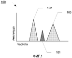
Фиг.1 - иллюстрация примера составного сигнала, включающего в себя полезный сигнал и источники помех от двух смежных каналов, согласно одному аспекту настоящей технологии;Figure 1 is an illustration of an example of a composite signal including a wanted signal and interference sources from two adjacent channels, in accordance with one aspect of the present technology;
Фиг.2 - структурная схема, иллюстрирующая устройство приемника согласно одному аспекту настоящей технологии;FIG. 2 is a block diagram illustrating a receiver device according to one aspect of the present technology; FIG.
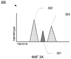
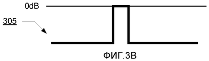
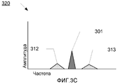
Фиг.3A, 3B и 3C - графические иллюстрации подавления ACI согласно одному аспекту настоящей технологии;3A, 3B, and 3C are graphical illustrations of ACI suppression according to one aspect of the present technology;
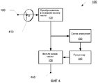
Фиг.4 - структурная схема, иллюстрирующая устройство приемника согласно одному аспекту настоящей технологии;4 is a block diagram illustrating a receiver device according to one aspect of the present technology;
Фиг.5A и 5B - графические иллюстрации подавления ACI согласно одному аспекту настоящей технологии;5A and 5B are graphical illustrations of ACI suppression according to one aspect of the present technology;
Фиг.6 - схема последовательности операций, иллюстрирующая способ подавления ACI согласно одному аспекту настоящей технологии;6 is a flowchart illustrating an ACI suppression method according to one aspect of the present technology;
Фиг.7 - структурная схема, иллюстрирующая компьютерную систему, посредством которой могут быть реализованы определенные аспекты настоящей технологии.7 is a block diagram illustrating a computer system by which certain aspects of the present technology can be implemented.
Осуществление изобретенияThe implementation of the invention
Фиг.1 представляет собой иллюстрацию примера принимаемого сигнала согласно одному аспекту настоящей технологии. Составной сигнал 100 включает в себя полезный сигнал 101 и источники помех 102 и 103 от двух смежных каналов. Каждый из источников помех 102 и 103 от смежных каналов имеет полосу пропускания (представленную шириной помехи вдоль горизонтальной оси частот) и позицию (например, частоту, на которой располагается центр этого источника помех).Figure 1 is an illustration of an example of a received signal in accordance with one aspect of the present technology. The
Некоторые приемники могут быть снабжены статическими фильтрами для подавления источников помех, таких как источники помех 102 и 103 от смежных каналов. Тем не менее, при использовании статических фильтров иногда подавляется слишком малая или слишком большая часть полосы пропускания (например, помехи полностью не подавляются, или подавляется некоторая часть полезного сигнала). В добавление, окружение, в котором имеют место источники помех, может динамически изменяться, так что статический фильтр только в исключительных случаях будет оптимально фильтровать принятый сигнал.Some receivers may be equipped with static filters to suppress interference sources, such as
Согласно одному аспекту настоящей технологии устройство приемника, такое как показанное на Фиг.2, обеспечивает усовершенствованное подавление ACI. Устройство 200 приемника включает в себя антенну 210, сконфигурированную, чтобы принимать составной сигнал 100 и чтобы предоставлять составной сигнал 100 в схему 220 измерения. Согласно еще одному аспекту настоящего раскрытия схема 220 измерения измеряет мощность и/или местоположение полезного сигнала 101 и источников помех 102 и 103 от смежных каналов и предоставляет информацию об измерении в процессор 230. Процессор 230 принимает эту информацию и генерирует инструкции для регулирования динамического фильтра 240, чтобы соответствовать местоположению измеряемых источников помех смежных каналов.According to one aspect of the present technology, a receiver device, such as that shown in FIG. 2, provides advanced ACI suppression. The
Согласно одному аспекту настоящей технологии динамический фильтр 240 может представлять собой полосовой фильтр. При такой конфигурации динамический фильтр 240 может регулироваться согласно местоположению полезного сигнала 101 (то есть, чтобы пропускать только частоты полезного сигнала). Такая конфигурация более подробно проиллюстрирована на Фиг.3A-3C.According to one aspect of the present technology, dynamic filter 240 may be a band-pass filter. With this configuration, the dynamic filter 240 can be adjusted according to the location of the wanted signal 101 (that is, to pass only the frequencies of the wanted signal). Such a configuration is illustrated in more detail in FIGS. 3A-3C.
На Фиг.3A-3C проиллюстрирована производительность динамического полосового фильтра согласно определенным аспектам настоящего раскрытия. Фиг.3A иллюстрирует составной сигнал 300 до фильтрации. Составной сигнал 300 включает в себя полезный сигнал 301 и источники помех 302 и 303 от двух смежных каналов. Соответственно, после измерения мощности и местоположения полезного сигнала и источников помех от двух смежных каналов процессор конфигурирует динамический полосовой фильтр 305 таким образом, чтобы пропускать только частоты, соответствующие полезному сигналу 301. Остальные частоты, включая частоты источников помех 302 и 305, подавляются полосовым фильтром 305. Результат этого подавления проиллюстрирован на Фиг.3C. В отфильтрованном сигнале 320 подавленные помехи (источники помех) 312 и 313 имеют гораздо меньшую амплитуду, в результате чего существенно повышается Отношение Сигнала к Шуму (Signal-to-Interference Ratio, SIR) отфильтрованного сигнала 320.3A-3C illustrate the performance of a dynamic bandpass filter in accordance with certain aspects of the present disclosure. 3A illustrates a
Согласно еще одному аспекту настоящей технологии динамический фильтр 240 может представлять собой узкополосный режекторный фильтр. При такой конфигурации динамический узкополосный режекторный фильтр 240 может быть отрегулирован, чтобы его рабочий диапазон соответствовал местоположению источников помех.According to another aspect of the present technology, the dynamic filter 240 may be a notch filter. With this configuration, the dynamic notch filter 240 can be adjusted so that its operating range matches the location of the interference sources.
Хотя динамический фильтр 240 показан как единый элемент уровня блока, когда динамический фильтр 240 представляет собой узкополосный режекторный фильтр, он может содержать множество динамических узкополосных режекторных фильтров согласно различным аспектам. Например, для такого сигнала, как сигнал 100, может быть желательным иметь два динамических узкополосных режекторных фильтра - один для подавления источников помех 102 и один для подавления источников помех 103. В одном аспекте, в котором количество источников помех от смежных каналов больше количества доступных динамических узкополосных режекторных фильтров, процессор 230 может быть сконфигурирован, чтобы выбирать, какие источники помех должны подавляться, а какие источники помех не должны подавляться, чтобы достичь наилучшего возможного SIR. Альтернативно, узкополосный режекторный фильтр может быть сконфигурирован, чтобы иметь достаточно широкую полосу пропускания и чтобы подавлять множество источников помех (при условии, что между этими помехами не будет полезного сигнала).Although the dynamic filter 240 is shown as a single block level element, when the dynamic filter 240 is a notch filter, it may comprise a plurality of dynamic notch filters in accordance with various aspects. For example, for a signal such as
Согласно еще одному аспекту настоящей технологии динамический фильтр может представлять собой фильтр низких частот. Подобная конфигурация может использоваться в устройстве приемника, в котором фильтрация происходит после преобразования полосы частот модулирующих сигналов. Фиг.4 представляет собой иллюстрацию одного такого устройства приемника согласно одному аспекту настоящей технологии. Схема 430 измерения измеряет мощность и местоположение полезного сигнала 101 и источников помех 102 и 103 от смежных каналов после их преобразования в основную полосу частот и предоставляет информацию об измерении в процессор 440. Процессор 440 принимает эту информацию и генерирует в ответ инструкции для регулирования фильтра 450 низких частот, чтобы обеспечить соответствие относительной мощности и местоположению измеренного полезного сигнала.According to another aspect of the present technology, the dynamic filter may be a low pass filter. A similar configuration can be used in a receiver device in which filtering occurs after the bandwidth of the baseband signal is converted. 4 is an illustration of one such receiver device in accordance with one aspect of the present technology.
Согласно одному аспекту настоящей технологии схема 430 измерения может быть сконфигурирована, чтобы измерять только мощность полезного сигнала и мощность источников помех 102 и 103 смежных каналов. В одном аспекте процессор 440 сконфигурирован, чтобы регулировать фильтр 450 низких частот, соответствующий относительной мощности полезного сигнала, относительно источников помех 102 и 103 смежных каналов. Так, если одни детектированные ACI имеют высокую мощность, полоса пропускания фильтра 450 низких частот сокращается на той стороне полезного сигнала, на которой присутствуют более мощные ACI.According to one aspect of the present technology, the
На Фиг.5A и 5B проиллюстрирована производительность динамического фильтра низких частот согласно определенным аспектам настоящего раскрытия. Фиг.5A иллюстрирует принятый сигнал до 500 и после 510 прохождения через фильтр низких частот. Принятый сигнал 500 включает в себя полезный сигнал 501 и источники помех 502 смежного канала. Соответственно, после измерения мощности и местоположения полезного сигнала 501 и ACI 502 процессор конфигурирует динамический фильтр 505 низких частот, чтобы извлечь полезный сигнал 501. Фильтр 505 низких частот конфигурируется, чтобы на правой стороне фильтра обеспечивалось усиленное подавление, так что фильтр 505 центрируется на отрицательной частоте.5A and 5B illustrate the performance of a dynamic low-pass filter according to certain aspects of the present disclosure. 5A illustrates a received signal up to 500 and after 510 passing through a low-pass filter. The received
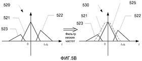
Фиг.5B иллюстрирует принятый сигнал до 520 и после 530 прохождения через фильтр низких частот. Принятый сигнал 520 включает в себя полезный сигнал 521 и источники помех 522 и 523 двух смежных каналов. ACI 521 мощнее, чем ACI 523. Соответственно, после измерения мощности и местоположения полезного сигнала 521 и ACI 522 и 532 процессор конфигурирует динамический фильтр 525 низких частот, чтобы извлечь полезный сигнал 521. Фильтр 525 низких частот конфигурируется, чтобы на обеих сторонах обеспечивалось сильное подавление, но чтобы на правой стороне было более сильное подавление. В результате фильтр 525 центрируется на отрицательной частоте.Fig. 5B illustrates a received signal before 520 and after 530 passing through a low-pass filter. The received
Согласно одному аспекту настоящей технологии алгоритм измерения мощности ACI оценивает уровень P center мощности сигнала и уровни P right и P left мощности ACI посредством фильтров, отцентрированных на частотах ƒcenter , ƒright , ƒleft Гц с полосой пропускания BW Det величиной 3 дБ. Тогда, подавление ACI посредством фильтра низких частот может выполняться по следующей логике:According to one aspect of the present technology, the ACI power measurement algorithm estimates the signal power level P center and the ACI power levels P right and P left using filters centered at ƒ center , ƒ right , ƒ left Hz with a 3 dB BW Det passband. Then, ACI suppression through a low-pass filter can be performed according to the following logic:
если (Pif (P centercenter /P/ P rightright <Пороговой Величины и P<Threshold Value and P centercenter /P/ P leftleft >Пороговой Величины){> Threshold Value) {
Пропустить принятый сигнал через фильтр низких частот с сокращенной полосой пропускания в 3 дБ на стороне более высокой частоты;Pass the received signal through a low-pass filter with a reduced passband of 3 dB on the higher frequency side;
}}
в противном случае, если (Potherwise, if (P centercenter /P/ P rightright >Пороговой Величины и P> Threshold Value and P centercenter /P/ P leftleft <Пороговой Величины){<Threshold Value) {
Пропустить принятый сигнал через фильтр низких частот с сокращенной полосой пропускания в 3 дБ на стороне более низкой частоты;Pass the received signal through a low-pass filter with a reduced passband of 3 dB on the lower frequency side;
}}
в противном случае, если (Potherwise, if (P centercenter /P/ P rightright <Пороговой Величины и P<Threshold Value and P centercenter /P/ P leftleft <Пороговой Величины){<Threshold Value) {
Пропустить принятый сигнал через фильтр низких частот с сокращенной полосой пропускания в 3 дБ на обеих сторонах;Pass the received signal through a low-pass filter with a reduced passband of 3 dB on both sides;
}}
Хотя измерение полезного сигнала и ACI было описано со ссылкой на конкретные алгоритмы, специалистам в данной области техники будет очевидно, что для измерения полезного сигнала и ACI может использоваться любой другой подходящий способ. Соответственно, объем настоящего изобретения не ограничивается описанными выше конкретными подходами для измерения полезного сигнала и ACI, и он охватывает любой способ измерения полезного сигнала и ACI, известный специалистам в данной области техники.Although the measurement of the wanted signal and ACI has been described with reference to specific algorithms, it will be apparent to those skilled in the art that any other suitable method can be used to measure the wanted signal and ACI. Accordingly, the scope of the present invention is not limited to the specific approaches described above for measuring the wanted signal and ACI, and it encompasses any method for measuring the wanted signal and ACI known to those skilled in the art.
Фиг.6 представляет собой схему последовательности операций, иллюстрирующую способ подавления ACI согласно одному аспекту настоящей технологии. Способ начинается на этапе 601, на котором принимают сигнал. Принятый сигнал включает в себя полезный сигнал и возможные источники помех от одного или более смежных каналов. На этапе 602 составной сигнал, опционально, преобразуют в основную полосу частот. На этапе 603 измеряют мощность и местоположение полезного сигнала и возможных источников помех одного или более смежных каналов. На этапе 604 регулируют местоположение динамического фильтра, чтобы извлечь полезный сигнал.6 is a flowchart illustrating an ACI suppression method according to one aspect of the present technology. The method begins at block 601, at which a signal is received. The received signal includes a useful signal and possible sources of interference from one or more adjacent channels. At block 602, the composite signal is optionally converted to the main frequency band. At 603, the power and location of the wanted signal and possible interference sources of one or more adjacent channels are measured. At 604, the location of the dynamic filter is adjusted to extract the desired signal.
Согласно одному аспекту измерение на этапе 603 может включать в себя измерение только мощности полезного сигнала и возможных источников помех от одного или более смежных каналов. При такой конфигурации этап 604 регулирования может включать в себя регулирование местоположения, по меньшей мере, одного динамического фильтра, соответствующего измеренным мощностям.According to one aspect, the measurement at 603 may include measuring only the wanted signal power and possible interference sources from one or more adjacent channels. With such a configuration, the regulation step 604 may include adjusting the location of the at least one dynamic filter corresponding to the measured powers.
Фиг.7 представляет собой структурную схему, которая иллюстрирует компьютерную систему 700, в которой может быть реализован аспект настоящей технологии. Компьютерная система 700 включает в себя шину 702 или другой механизм связи для передачи информации, а также процессор 704, соединенный с шиной 702 для обработки информации. Компьютерная система 700 также включает в себя память 706, такую как ОЗУ или динамическое устройство хранения, которое соединено с шиной 702 и предназначено для хранения информации и инструкций, которые должны выполняться процессором 704. Память 706 также может использоваться для временного хранения переменной или иной промежуточной информации в течение выполнения инструкций процессором 704. Компьютерная система 700 дополнительно включает в себя устройство 710 хранения данных, такое как магнитный диск или оптический диск, соединенное с шиной 702 и предназначенное для хранения информации и инструкций.7 is a block diagram that illustrates a
Компьютерная система 700 может быть соединена через модуль 708 ввода/вывода с устройством отображения (не показано), таким как дисплей на электронно-лучевой трубке или жидкокристаллический дисплей для отображения информации пользователю компьютера. Устройство ввода, такое как, например, клавиатура или мышь, также может быть соединено с компьютерной системой 700 через модуль 708 ввода/вывода для передачи информации и выборов команд в процессор 704.
Согласно одному аспекту настоящей технологии подавление ACI выполняется компьютерной системой 700 при исполнении процессором 704 одной или более последовательностей из одной или более инструкций, содержащихся в памяти 706. Такие инструкции могут быть считаны в память 705 из другого машиночитаемого носителя, такого как устройство 710 хранения данных. Выполнение последовательностей инструкций, содержащихся в главной памяти 706, приводит процессор 704 к выполнению описанных этапов процесса. Для исполнения последовательностей инструкций, содержащихся в памяти 706, также могут использоваться один или более процессоров в многопроцессорной конфигурации. Альтернативно, для реализации различных аспектов взамен или в добавление к программным инструкциям может использоваться аппаратная схема. Так, настоящие аспекты не ограничиваются какой-либо конкретной комбинацией аппаратного обеспечения и программного обеспечения.According to one aspect of the present technology, ACI cancellation is performed by a
Термин "машиночитаемый носитель" в использованном здесь значении обозначает любой носитель, который участвует в предоставлении инструкций в процессор 704 для выполнения. Такой носитель может принять множество форм, включая, но не ограничиваясь перечисленным, энергонезависимую память, энергозависимую память и средство передачи. Энергонезависимые носители включают в себя, например, оптические или магнитные диски, такие как устройство 710 хранения данных. Энергозависимые носители включают в себя динамическую память, такую как память 706. Средство передачи включает в себя коаксиальные кабели, медные провода и волоконно-оптические линии, включая провода, которые образуют шину 702. Средство передачи также может принять форму акустических или световых волн, таких как волны, генерируемые при радиочастотной или инфракрасной передаче данных. Обычные формы машиночитаемых носителей включают в себя, например, дискету, гибкий диск, жесткий диск, магнитную ленту, любой другой магнитный носитель, диск CD-ROM, диск DVD, любой другой оптический носитель, перфокарты, бумажные ленты, любой другой физический носитель с шаблонами из дырок, ОЗУ, ППЗУ, ЭППЗУ, флэш-память, любой другой чип или картридж памяти, несущую волну, или любой другой носитель, который может быть считан компьютером.The term “computer readable medium” as used herein means any medium that is involved in providing instructions to
Специалистам в данной области техники будет очевидно, что различные иллюстративные блоки, модули, элементы, компоненты, способы и алгоритмы, описанные в настоящем документе, могут быть реализованы как электронное аппаратное обеспечение, компьютерное программное обеспечение или их комбинации. Дополнительно, перечисленные могут быть разделены иначе, чем описано выше. Для ясной иллюстрации этой взаимозаменяемости аппаратного обеспечения и программного обеспечения, различные иллюстративные блоки, модули, элементы, компоненты, способы и алгоритмы описаны в терминах их функциональности. Способ реализации такой функции - как аппаратное обеспечение или как программное обеспечение - зависит от конкретного приложения и конструктивных ограничений, налагаемых на систему в целом. Специалисты в данной области техники могут реализовать описанные функциональные возможности различными способами для каждого конкретного приложения.It will be apparent to those skilled in the art that the various illustrative blocks, modules, elements, components, methods, and algorithms described herein can be implemented as electronic hardware, computer software, or combinations thereof. Additionally, the listed may be divided differently than described above. To clearly illustrate this interchangeability of hardware and software, various illustrative blocks, modules, elements, components, methods, and algorithms are described in terms of their functionality. The way this function is implemented, such as hardware or software, depends on the particular application and the design constraints imposed on the system as a whole. Skilled artisans may implement the described functionality in varying ways for each particular application.
Следует понимать, что конкретный порядок или иерархия этапов или блоков в раскрытых процессах является только примером. На основании структурных предпочтений, конкретный порядок или иерархия этапов или блоков в процессах может быть изменена. Пункты прилагающейся формулы изобретения, определяющие способы, представляют элементы различных этапов в иллюстративном порядке, и они не предназначены для ограничения конкретным представленным порядком или иерархией.It should be understood that the specific order or hierarchy of steps or blocks in the disclosed processes is only an example. Based on structural preferences, the specific order or hierarchy of steps or blocks in processes can be changed. The appended claims defining the methods represent elements of the various steps in an illustrative manner and are not intended to be limited to the particular order or hierarchy presented.
Вышеизложенное описание приведено для того, чтобы специалист в данной области техники мог реализовать различные описанные аспекты. Специалистам в данной области техники будут очевидны различные модификации этих аспектов, и общие принципы, определенные в настоящем документе, могут быть применены к другим аспектам. Соответственно, формула изобретения не ограничивается показанными в настоящем документе аспектами, и ей следует сопоставить полный объем, причем если не указано иного, ссылки на определенный элемент в единственном числе обозначают не "один и единственный", а "один или более". Если не указано иного, термин "некоторый" обозначает один или более элементов. Местоимения мужского рода (например, его) включают в себя женский и средний род (например, ее и его), и наоборот. Все структурные и функциональные эквиваленты элементов различных аспектов, которые описаны в настоящем раскрытии и которые известны или станут известны специалистам в данной области техники, явным образом включены в настоящий документ посредством ссылки, и они охватываются прилагаемой формулой изобретения. Более того, ничто из раскрытого в настоящем документе не предназначено для предоставления общественности, независимо от того, что подобное раскрытие в явном виде приведено в формуле изобретения. Ни один элемент формулы изобретения не должен истолковываться согласно условиям §112 раздела 35 кодекса законов США, если элемент в явной форме не выражен посредством фразы "средство для" или - в случае элемента формулы изобретения на способ - посредством фразы "этап для".The foregoing description is provided so that a person skilled in the art can implement the various described aspects. Various modifications to these aspects will be apparent to those skilled in the art, and the general principles defined herein may be applied to other aspects. Accordingly, the claims are not limited to the aspects shown herein, and should be compared in their entirety, and unless otherwise indicated, references to a specific element in the singular indicate not “one and only” but “one or more”. Unless otherwise indicated, the term "some" refers to one or more elements. Masculine pronouns (e.g., his) include feminine and neuter gender (e.g., her and his), and vice versa. All structural and functional equivalents of elements of various aspects, which are described in the present disclosure and which are known or will become known to specialists in this field of technology, are expressly incorporated herein by reference, and they are covered by the attached claims. Moreover, none of the disclosures herein is intended to be publicly available, regardless of whether such disclosure is explicitly set forth in the claims. No element of the claims should be construed in accordance with the terms of Section 112 of Section 35 of the Code of the United States Laws, unless the element is explicitly expressed by the phrase "means for" or - in the case of the element of the claims by way of - the phrase "step for".
Claims (37)
принимают составной сигнал, включающий в себя полезный сигнал и источники помех от одного или более смежных каналов;
измеряют мощность упомянутого полезного сигнала и источников помех от одного или более смежных каналов; и
регулируют местоположение, по меньшей мере, одного динамического фильтра, включая центр, по меньшей мере, одного динамического фильтра на основе мощности упомянутого полезного сигнала относительно мощности источников помех от одного или более смежных каналов, чтобы извлечь упомянутый полезный сигнал.1. A method for suppressing interference from adjacent channels (ACI), comprising stages in which:
receiving a composite signal including a useful signal and interference sources from one or more adjacent channels;
measuring the power of said useful signal and interference sources from one or more adjacent channels; and
adjusting the location of the at least one dynamic filter, including the center of the at least one dynamic filter, based on the power of said useful signal relative to the power of interference sources from one or more adjacent channels to extract said useful signal.
посредством процессора принимают информацию об измерении полезного сигнала и возможных источников помех от одного или более смежных каналов; и
посредством процессора в ответ на принятую информацию генерируют инструкции для регулирования местоположения, по меньшей мере, одного динамического фильтра.12. The method according to claim 1, in which at the stage of regulating the location of at least one dynamic filter:
by the processor receive information about the measurement of the useful signal and possible sources of interference from one or more adjacent channels; and
by the processor, in response to the received information, instructions are generated for adjusting the location of the at least one dynamic filter.
регулирование местоположения, по меньшей мере, одного динамического фильтра низких частот, чтобы извлечь упомянутый полезный сигнал, включающее в себя:
определение первого соотношения первой частоты ко второй частоте и второго соотношения первой частоты к третьей частоте; и
пропускание упомянутого полезного сигнала через, по меньшей мере, один динамический фильтр низких частот, имеющий заданную сокращенную полосу пропускания на стороне более высокой частоты, когда первое соотношение меньше, чем заданное пороговое значение, а второе соотношение больше, чем заданное пороговое значение;
пропускание упомянутого полезного сигнала через, по меньшей мере, один динамический фильтр низких частот, имеющий заданную сокращенную полосу пропускания на стороне более низкой частоты, когда первое соотношение больше, чем заданное пороговое значение, а второе соотношение меньше, чем заданное пороговое значение; и
пропускание упомянутого полезного сигнала через, по меньшей мере, один динамический фильтр низких частот, имеющий заданную сокращенную полосу пропускания на обеих сторонах более низкой и более высокой частоты, когда первое соотношение меньше, чем заданное пороговое значение, и второе соотношение меньше, чем заданное пороговое значение.13. The method according to claim 1, in which at least one dynamic filter is a low-pass filter, the method further comprising:
adjusting the location of the at least one dynamic low-pass filter to extract said useful signal, including:
determining a first ratio of a first frequency to a second frequency and a second ratio of a first frequency to a third frequency; and
passing said useful signal through at least one dynamic low-pass filter having a predetermined reduced passband on the higher frequency side when the first ratio is less than a predetermined threshold value and the second ratio is greater than a predetermined threshold value;
passing said useful signal through at least one dynamic low-pass filter having a predetermined reduced passband on the lower frequency side when the first ratio is greater than a predetermined threshold value and the second ratio is less than a predetermined threshold value; and
passing said useful signal through at least one dynamic low-pass filter having a predetermined reduced passband on both sides of a lower and higher frequency when the first ratio is less than a predetermined threshold value and the second ratio is less than a predetermined threshold value .
антенну, сконфигурированную, чтобы принимать составной сигнал, включающий в себя полезный сигнал и источники помех от одного или более смежных каналов;
схему измерения помех, сконфигурированную, чтобы измерять мощность упомянутого полезного сигнала и источников помех от одного или более смежных каналов;
по меньшей мере, один динамический фильтр, сконфигурированный, чтобы извлекать полезный сигнал; и
процессор, сконфигурированный, чтобы регулировать местоположение, по меньшей мере, одного динамического фильтра, включая центр упомянутого фильтра, на основе мощности упомянутого полезного сигнала относительно мощности источников помех от одного или более смежных каналов, чтобы извлечь упомянутый полезный сигнал.16. A receiver device comprising:
an antenna configured to receive a composite signal including a wanted signal and interference sources from one or more adjacent channels;
an interference measuring circuit configured to measure the power of said useful signal and interference sources from one or more adjacent channels;
at least one dynamic filter configured to extract a useful signal; and
a processor configured to adjust the location of the at least one dynamic filter, including the center of said filter, based on the power of said useful signal relative to the power of interference sources from one or more adjacent channels to extract said useful signal.
определение первого соотношения первой частоты ко второй частоте и второго соотношения первой частоты к третьей частоте; и
пропускание упомянутого полезного сигнала через, по меньшей мере, один динамический фильтр низких частот, имеющий заданную сокращенную полосу пропускания на стороне более высокой частоты, когда первое соотношение меньше, чем заданное пороговое значение, а второе соотношение больше, чем заданное пороговое значение;
пропускание упомянутого полезного сигнала через, по меньшей мере, один динамический фильтр низких частот, имеющий заданную сокращенную полосу пропускания на стороне более низкой частоты, когда первое соотношение больше, чем заданное пороговое значение, а второе соотношение меньше, чем заданное пороговое значение; и
пропускание упомянутого полезного сигнала через, по меньшей мере, один динамический фильтр низких частот, имеющий заданную сокращенную полосу пропускания на обеих сторонах более низкой и более высокой частоты, когда первое соотношение меньше, чем заданное пороговое значение, и второе соотношение меньше, чем заданное пороговое значение.27. The receiver device according to clause 16, in which at least one dynamic filter is a low-pass filter, and adjusting the location of at least one dynamic low-pass filter to extract said useful signal, includes:
determining a first ratio of a first frequency to a second frequency and a second ratio of a first frequency to a third frequency; and
passing said useful signal through at least one dynamic low-pass filter having a predetermined reduced passband on the higher frequency side when the first ratio is less than a predetermined threshold value and the second ratio is greater than a predetermined threshold value;
passing said useful signal through at least one dynamic low-pass filter having a predetermined reduced passband on the lower frequency side when the first ratio is greater than a predetermined threshold value and the second ratio is less than a predetermined threshold value; and
passing said useful signal through at least one dynamic low-pass filter having a predetermined reduced passband on both sides of a lower and higher frequency when the first ratio is less than a predetermined threshold value and the second ratio is less than a predetermined threshold value .
прием составного сигнала, включающего в себя полезный сигнал и источники помех от одного или более смежных каналов;
измерение мощности упомянутого полезного сигнала и источников помех от одного или более смежных каналов; и
регулирование местоположения, по меньшей мере, одного динамического фильтра, включая центр упомянутого фильтра, на основе мощности упомянутого полезного сигнала относительно мощности источников помех от одного или более смежных каналов, чтобы извлечь упомянутый полезный сигнал.30. A machine-readable medium containing instructions stored therein, which, when executed on a processor, enables the processor to execute a method for suppressing interference from adjacent channels, said instructions comprising:
receiving a composite signal including a useful signal and interference sources from one or more adjacent channels;
measuring the power of said useful signal and interference sources from one or more adjacent channels; and
adjusting the location of the at least one dynamic filter, including the center of said filter, based on the power of said useful signal relative to the power of interference sources from one or more adjacent channels to extract said useful signal.
определение первого соотношения первой частоты ко второй частоте и второго соотношения первой частоты к третьей частоте; и
пропускание упомянутого полезного сигнала через, по меньшей мере, один динамический фильтр низких частот, имеющий заданную сокращенную полосу пропускания на стороне более высокой частоты, когда первое соотношение меньше, чем заданное пороговое значение, а второе соотношение больше, чем заданное пороговое значение;
пропускание упомянутого полезного сигнала через, по меньшей мере, один динамический фильтр низких частот, имеющий заданную сокращенную полосу пропускания на стороне более низкой частоты, когда первое соотношение больше, чем заданное пороговое значение, а второе соотношение меньше, чем заданное пороговое значение; и
пропускание упомянутого полезного сигнала через, по меньшей мере, один динамический фильтр низких частот, имеющий заданную сокращенную полосу пропускания на обеих сторонах более низкой и более высокой частоты, когда первое соотношение меньше, чем заданное пороговое значение, и второе соотношение меньше, чем заданное пороговое значение.35. The computer-readable medium of claim 30, wherein the at least one dynamic filter is at least one dynamic low-pass filter, and adjusting the location of the at least one dynamic low-pass filter to further extract said useful signal contains:
determining a first ratio of a first frequency to a second frequency and a second ratio of a first frequency to a third frequency; and
passing said useful signal through at least one dynamic low-pass filter having a predetermined reduced passband on the higher frequency side when the first ratio is less than a predetermined threshold value and the second ratio is greater than a predetermined threshold value;
passing said useful signal through at least one dynamic low-pass filter having a predetermined reduced passband on the lower frequency side when the first ratio is greater than a predetermined threshold value and the second ratio is less than a predetermined threshold value; and
passing said useful signal through at least one dynamic low-pass filter having a predetermined reduced passband on both sides of a lower and higher frequency when the first ratio is less than a predetermined threshold value and the second ratio is less than a predetermined threshold value .
измерять мощность полезного сигнала и мощность источников помех от одного или более смежных каналов; и
регулировать местоположение, по меньшей мере, одного динамического фильтра, включая центр упомянутого фильтра, чтобы соответствовать мощности полезного сигнала относительно мощности источников помех от одного или более смежных каналов.36. An ACI suppressor processor configured to:
measure the useful signal power and the power of interference sources from one or more adjacent channels; and
adjust the location of the at least one dynamic filter, including the center of said filter, to match the power of the wanted signal relative to the power of the interference sources from one or more adjacent channels.
регулировать местоположение, по меньшей мере, одного динамического фильтра, чтобы соответствовать местоположению полезного сигнала относительно местоположения источников помех от одного или более смежных каналов. 37. The processor according to clause 36, which is further configured to measure the location of interference sources from one or more adjacent channels; and
adjust the location of the at least one dynamic filter to match the location of the wanted signal relative to the location of the interference sources from one or more adjacent channels.
Applications Claiming Priority (2)
| Application Number | Priority Date | Filing Date | Title |
|---|---|---|---|
| US12/165,667 US20100002815A1 (en) | 2008-07-01 | 2008-07-01 | Dynamic filtering for adjacent channel interference suppression |
| US12/165,667 | 2008-07-01 |
Publications (2)
| Publication Number | Publication Date |
|---|---|
| RU2011103461A RU2011103461A (en) | 2012-08-10 |
| RU2466498C2 true RU2466498C2 (en) | 2012-11-10 |
Family
ID=41165577
Family Applications (1)
| Application Number | Title | Priority Date | Filing Date |
|---|---|---|---|
| RU2011103461/08A RU2466498C2 (en) | 2008-07-01 | 2009-06-30 | Dynamic filtering for adjacent channel interference suppression |
Country Status (10)
| Country | Link |
|---|---|
| US (1) | US20100002815A1 (en) |
| EP (1) | EP2313981A1 (en) |
| JP (1) | JP2011527160A (en) |
| KR (1) | KR101230355B1 (en) |
| CN (1) | CN102077473A (en) |
| BR (1) | BRPI0914113A2 (en) |
| CA (1) | CA2728305C (en) |
| RU (1) | RU2466498C2 (en) |
| TW (1) | TWI436600B (en) |
| WO (1) | WO2010002946A1 (en) |
Families Citing this family (7)
| Publication number | Priority date | Publication date | Assignee | Title |
|---|---|---|---|---|
| US8116713B2 (en) * | 2008-11-26 | 2012-02-14 | Visteon Global Technologies, Inc. | Automatic bandwidth control with high-deviation detection |
| KR101310721B1 (en) * | 2009-08-11 | 2013-09-24 | 퀄컴 인코포레이티드 | Adaptive transmission (tx)/reception (rx) pulse shaping filter for femtocell base stations and mobile stations within a network |
| US9143182B2 (en) * | 2012-04-24 | 2015-09-22 | Lockheed Martin Corporation | Adaptive cosite arbitration system |
| CN103685095B (en) * | 2013-12-18 | 2017-01-04 | 北京创毅视讯科技有限公司 | A kind of method and apparatus realizing monkey chatter suppression |
| CN104753545B (en) * | 2013-12-30 | 2019-02-15 | 中兴通讯股份有限公司 | A kind of IF process method, apparatus and base station |
| US9350483B2 (en) * | 2014-01-15 | 2016-05-24 | Qualcomm Incorporated | Mitigate adjacent channel interference and non-Wi-Fi interference |
| CN104902054B (en) * | 2015-06-24 | 2018-07-06 | 小米科技有限责任公司 | Filter out the method and device of the interference frequency point of mobile terminal |
Citations (6)
| Publication number | Priority date | Publication date | Assignee | Title |
|---|---|---|---|---|
| RU2205422C1 (en) * | 2002-04-19 | 2003-05-27 | Открытое акционерное общество "Научно-производственное объединение "Алмаз" им. акад. А.А.Расплетина" | Multichannel correlation-filtration receiving facility |
| EP1379003A2 (en) * | 2002-07-02 | 2004-01-07 | Pioneer Corporation | Receiver with adjacent interfering wave elimination function |
| EP1603245A2 (en) * | 2004-05-31 | 2005-12-07 | Pioneer Corporation | Adjacent interference detecting device, adjacent interference removing device, and receiving device |
| FR2871966A1 (en) * | 2004-06-17 | 2005-12-23 | Nortel Networks Ltd | Signal processing method for wireless communication receiver, involves estimating interference level in block at respective frequency bands, for selecting filtering parameters, and analyzing filtered block for estimating channel response |
| US7039093B2 (en) * | 2002-06-14 | 2006-05-02 | Siemens Communications, Inc. | Arrangement for adaptive baseband filter selection |
| RU2289202C2 (en) * | 2004-11-23 | 2006-12-10 | Зао "Элвиис" | Digital multi-channel reprogrammable reception path |
Family Cites Families (10)
| Publication number | Priority date | Publication date | Assignee | Title |
|---|---|---|---|---|
| DE3416493A1 (en) * | 1984-05-04 | 1985-11-07 | Standard Elektrik Lorenz Ag, 7000 Stuttgart | OPTICAL RECEIVING DEVICE |
| US5151939A (en) * | 1990-03-21 | 1992-09-29 | Delco Electronics Corporation | Adaptive audio processor for am stereo signals |
| JP2874457B2 (en) * | 1992-05-29 | 1999-03-24 | 日本電気株式会社 | Demodulator |
| DE4319457C2 (en) * | 1993-06-11 | 1997-09-04 | Blaupunkt Werke Gmbh | Circuit arrangement for adjacent channel detection and suppression in an FM radio receiver |
| US6026129A (en) * | 1996-03-27 | 2000-02-15 | Matsushita Electric Industrial Co., Ltd. | Radio receiving apparatus for receiving communication signals of different bandwidths |
| JP3660050B2 (en) * | 1996-03-27 | 2005-06-15 | 松下電器産業株式会社 | Receiver |
| EP1419583B1 (en) * | 2001-08-23 | 2005-02-16 | Siemens Aktiengesellschaft | Adaptive filtering method and filter for filtering a radio signal in a mobile radio-communication system |
| US6901243B2 (en) * | 2001-11-08 | 2005-05-31 | Qualcomm, Incorporated | Method and apparatus for mitigating adjacent channel interference in a wireless communication system |
| JP3465707B1 (en) * | 2002-05-27 | 2003-11-10 | 日本電気株式会社 | Carrier sense multiple access receiver and its interference suppression method |
| JP2006166367A (en) * | 2004-12-10 | 2006-06-22 | Pioneer Electronic Corp | High frequency receiver and method of reducing adjacent interference wave |
-
2008
- 2008-07-01 US US12/165,667 patent/US20100002815A1/en not_active Abandoned
-
2009
- 2009-06-30 WO PCT/US2009/049331 patent/WO2010002946A1/en active Application Filing
- 2009-06-30 KR KR1020117002610A patent/KR101230355B1/en not_active IP Right Cessation
- 2009-06-30 CN CN200980124970XA patent/CN102077473A/en active Pending
- 2009-06-30 RU RU2011103461/08A patent/RU2466498C2/en not_active IP Right Cessation
- 2009-06-30 BR BRPI0914113A patent/BRPI0914113A2/en not_active IP Right Cessation
- 2009-06-30 EP EP09774396A patent/EP2313981A1/en not_active Withdrawn
- 2009-06-30 CA CA2728305A patent/CA2728305C/en not_active Expired - Fee Related
- 2009-06-30 JP JP2011516839A patent/JP2011527160A/en active Pending
- 2009-07-01 TW TW098122284A patent/TWI436600B/en not_active IP Right Cessation
Patent Citations (6)
| Publication number | Priority date | Publication date | Assignee | Title |
|---|---|---|---|---|
| RU2205422C1 (en) * | 2002-04-19 | 2003-05-27 | Открытое акционерное общество "Научно-производственное объединение "Алмаз" им. акад. А.А.Расплетина" | Multichannel correlation-filtration receiving facility |
| US7039093B2 (en) * | 2002-06-14 | 2006-05-02 | Siemens Communications, Inc. | Arrangement for adaptive baseband filter selection |
| EP1379003A2 (en) * | 2002-07-02 | 2004-01-07 | Pioneer Corporation | Receiver with adjacent interfering wave elimination function |
| EP1603245A2 (en) * | 2004-05-31 | 2005-12-07 | Pioneer Corporation | Adjacent interference detecting device, adjacent interference removing device, and receiving device |
| FR2871966A1 (en) * | 2004-06-17 | 2005-12-23 | Nortel Networks Ltd | Signal processing method for wireless communication receiver, involves estimating interference level in block at respective frequency bands, for selecting filtering parameters, and analyzing filtered block for estimating channel response |
| RU2289202C2 (en) * | 2004-11-23 | 2006-12-10 | Зао "Элвиис" | Digital multi-channel reprogrammable reception path |
Also Published As
| Publication number | Publication date |
|---|---|
| CA2728305A1 (en) | 2010-01-07 |
| CN102077473A (en) | 2011-05-25 |
| BRPI0914113A2 (en) | 2015-10-20 |
| RU2011103461A (en) | 2012-08-10 |
| CA2728305C (en) | 2014-04-08 |
| WO2010002946A1 (en) | 2010-01-07 |
| TWI436600B (en) | 2014-05-01 |
| US20100002815A1 (en) | 2010-01-07 |
| KR101230355B1 (en) | 2013-02-06 |
| EP2313981A1 (en) | 2011-04-27 |
| KR20110026509A (en) | 2011-03-15 |
| TW201008142A (en) | 2010-02-16 |
| JP2011527160A (en) | 2011-10-20 |
Similar Documents
| Publication | Publication Date | Title |
|---|---|---|
| RU2466498C2 (en) | Dynamic filtering for adjacent channel interference suppression | |
| US8577676B2 (en) | Method and apparatus for maintaining speech audibility in multi-channel audio with minimal impact on surround experience | |
| US8379869B2 (en) | Method and system for acoustic shock protection | |
| US7072831B1 (en) | Estimating the noise components of a signal | |
| KR20210020751A (en) | Systems and methods for providing personalized audio replay on a plurality of consumer devices | |
| CN110706693B (en) | Method and device for determining voice endpoint, storage medium and electronic device | |
| CN106878866A (en) | Acoustic signal processing method, device and terminal | |
| CN109410975B (en) | Voice noise reduction method, device and storage medium | |
| KR20080077157A (en) | Filter and method for suppressing effects of adjacent-channel interference | |
| CN113539285B (en) | Audio signal noise reduction method, electronic device and storage medium | |
| WO2021136427A1 (en) | Method of reducing coexistence interference, communication device and readable storage medium | |
| TWI459381B (en) | Speech enhancement method | |
| CN112821972B (en) | Frequency point signal processing method and device, terminal and storage medium | |
| US10667055B2 (en) | Separated audio analysis and processing | |
| CN112711045B (en) | Method and device for processing interference in navigation signal | |
| US20240137713A1 (en) | Howling suppression method, hearing aid, and storage medium | |
| US11798572B2 (en) | Method and apparatus for improving signal-to-noise ratio of microphone signal | |
| CN109547923B (en) | Positioning signal processing method, communication terminal and storage medium | |
| CN117476020A (en) | Audio dynamic range control method, device, electronic equipment and storage medium | |
| JP2015119404A (en) | Multi-pass determination device | |
| US20110228833A1 (en) | Wireless communication apparatus, signal processing method, and non-transitory computer readable medium |
Legal Events
| Date | Code | Title | Description |
|---|---|---|---|
| MM4A | The patent is invalid due to non-payment of fees |
Effective date: 20160701 |