RU2407655C2 - System and method of distance indication - Google Patents
System and method of distance indication Download PDFInfo
- Publication number
- RU2407655C2 RU2407655C2 RU2008134330/11A RU2008134330A RU2407655C2 RU 2407655 C2 RU2407655 C2 RU 2407655C2 RU 2008134330/11 A RU2008134330/11 A RU 2008134330/11A RU 2008134330 A RU2008134330 A RU 2008134330A RU 2407655 C2 RU2407655 C2 RU 2407655C2
- Authority
- RU
- Russia
- Prior art keywords
- transceiver
- electromagnetic wave
- distance
- transmitter
- specified
- Prior art date
Links
Images

Classifications
-
- B—PERFORMING OPERATIONS; TRANSPORTING
- B60—VEHICLES IN GENERAL
- B60G—VEHICLE SUSPENSION ARRANGEMENTS
- B60G17/00—Resilient suspensions having means for adjusting the spring or vibration-damper characteristics, for regulating the distance between a supporting surface and a sprung part of vehicle or for locking suspension during use to meet varying vehicular or surface conditions, e.g. due to speed or load
- B60G17/015—Resilient suspensions having means for adjusting the spring or vibration-damper characteristics, for regulating the distance between a supporting surface and a sprung part of vehicle or for locking suspension during use to meet varying vehicular or surface conditions, e.g. due to speed or load the regulating means comprising electric or electronic elements
- B60G17/019—Resilient suspensions having means for adjusting the spring or vibration-damper characteristics, for regulating the distance between a supporting surface and a sprung part of vehicle or for locking suspension during use to meet varying vehicular or surface conditions, e.g. due to speed or load the regulating means comprising electric or electronic elements characterised by the type of sensor or the arrangement thereof
- B60G17/01933—Velocity, e.g. relative velocity-displacement sensors
-
- B—PERFORMING OPERATIONS; TRANSPORTING
- B60—VEHICLES IN GENERAL
- B60G—VEHICLE SUSPENSION ARRANGEMENTS
- B60G17/00—Resilient suspensions having means for adjusting the spring or vibration-damper characteristics, for regulating the distance between a supporting surface and a sprung part of vehicle or for locking suspension during use to meet varying vehicular or surface conditions, e.g. due to speed or load
- B60G17/02—Spring characteristics, e.g. mechanical springs and mechanical adjusting means
- B60G17/04—Spring characteristics, e.g. mechanical springs and mechanical adjusting means fluid spring characteristics
- B60G17/052—Pneumatic spring characteristics
-
- F—MECHANICAL ENGINEERING; LIGHTING; HEATING; WEAPONS; BLASTING
- F16—ENGINEERING ELEMENTS AND UNITS; GENERAL MEASURES FOR PRODUCING AND MAINTAINING EFFECTIVE FUNCTIONING OF MACHINES OR INSTALLATIONS; THERMAL INSULATION IN GENERAL
- F16F—SPRINGS; SHOCK-ABSORBERS; MEANS FOR DAMPING VIBRATION
- F16F9/00—Springs, vibration-dampers, shock-absorbers, or similarly-constructed movement-dampers using a fluid or the equivalent as damping medium
- F16F9/02—Springs, vibration-dampers, shock-absorbers, or similarly-constructed movement-dampers using a fluid or the equivalent as damping medium using gas only or vacuum
- F16F9/04—Springs, vibration-dampers, shock-absorbers, or similarly-constructed movement-dampers using a fluid or the equivalent as damping medium using gas only or vacuum in a chamber with a flexible wall
- F16F9/05—Springs, vibration-dampers, shock-absorbers, or similarly-constructed movement-dampers using a fluid or the equivalent as damping medium using gas only or vacuum in a chamber with a flexible wall the flexible wall being of the rolling diaphragm type
-
- G—PHYSICS
- G01—MEASURING; TESTING
- G01S—RADIO DIRECTION-FINDING; RADIO NAVIGATION; DETERMINING DISTANCE OR VELOCITY BY USE OF RADIO WAVES; LOCATING OR PRESENCE-DETECTING BY USE OF THE REFLECTION OR RERADIATION OF RADIO WAVES; ANALOGOUS ARRANGEMENTS USING OTHER WAVES
- G01S13/00—Systems using the reflection or reradiation of radio waves, e.g. radar systems; Analogous systems using reflection or reradiation of waves whose nature or wavelength is irrelevant or unspecified
- G01S13/74—Systems using reradiation of radio waves, e.g. secondary radar systems; Analogous systems
- G01S13/82—Systems using reradiation of radio waves, e.g. secondary radar systems; Analogous systems wherein continuous-type signals are transmitted
- G01S13/825—Systems using reradiation of radio waves, e.g. secondary radar systems; Analogous systems wherein continuous-type signals are transmitted with exchange of information between interrogator and responder
-
- B—PERFORMING OPERATIONS; TRANSPORTING
- B60—VEHICLES IN GENERAL
- B60G—VEHICLE SUSPENSION ARRANGEMENTS
- B60G2202/00—Indexing codes relating to the type of spring, damper or actuator
- B60G2202/10—Type of spring
- B60G2202/15—Fluid spring
- B60G2202/152—Pneumatic spring
-
- B—PERFORMING OPERATIONS; TRANSPORTING
- B60—VEHICLES IN GENERAL
- B60G—VEHICLE SUSPENSION ARRANGEMENTS
- B60G2204/00—Indexing codes related to suspensions per se or to auxiliary parts
- B60G2204/10—Mounting of suspension elements
- B60G2204/11—Mounting of sensors thereon
- B60G2204/111—Mounting of sensors thereon on pneumatic springs
-
- B—PERFORMING OPERATIONS; TRANSPORTING
- B60—VEHICLES IN GENERAL
- B60G—VEHICLE SUSPENSION ARRANGEMENTS
- B60G2400/00—Indexing codes relating to detected, measured or calculated conditions or factors
- B60G2400/25—Stroke; Height; Displacement
- B60G2400/252—Stroke; Height; Displacement vertical
-
- B—PERFORMING OPERATIONS; TRANSPORTING
- B60—VEHICLES IN GENERAL
- B60G—VEHICLE SUSPENSION ARRANGEMENTS
- B60G2401/00—Indexing codes relating to the type of sensors based on the principle of their operation
- B60G2401/17—Magnetic/Electromagnetic
- B60G2401/174—Radar
-
- B—PERFORMING OPERATIONS; TRANSPORTING
- B60—VEHICLES IN GENERAL
- B60G—VEHICLE SUSPENSION ARRANGEMENTS
- B60G2401/00—Indexing codes relating to the type of sensors based on the principle of their operation
- B60G2401/17—Magnetic/Electromagnetic
- B60G2401/176—Radio or audio sensitive means, e.g. Ultrasonic
-
- F—MECHANICAL ENGINEERING; LIGHTING; HEATING; WEAPONS; BLASTING
- F16—ENGINEERING ELEMENTS AND UNITS; GENERAL MEASURES FOR PRODUCING AND MAINTAINING EFFECTIVE FUNCTIONING OF MACHINES OR INSTALLATIONS; THERMAL INSULATION IN GENERAL
- F16F—SPRINGS; SHOCK-ABSORBERS; MEANS FOR DAMPING VIBRATION
- F16F2230/00—Purpose; Design features
- F16F2230/08—Sensor arrangement
Landscapes
- Engineering & Computer Science (AREA)
- Mechanical Engineering (AREA)
- Radar, Positioning & Navigation (AREA)
- Remote Sensing (AREA)
- General Engineering & Computer Science (AREA)
- Computer Networks & Wireless Communication (AREA)
- Physics & Mathematics (AREA)
- General Physics & Mathematics (AREA)
- Vehicle Body Suspensions (AREA)
- Radar Systems Or Details Thereof (AREA)
- Arrangements For Transmission Of Measured Signals (AREA)
Abstract
Description
ПРЕДПОСЫЛКИ СОЗДАНИЯ ИЗОБРЕТЕНИЯBACKGROUND OF THE INVENTION
Настоящее изобретение относится к технике измерения расстояния и, более точно, к системе и способу для индикации расстояния между связанными между собой конструкционными элементами, используя модуляцию электромагнитной волны.The present invention relates to techniques for measuring distance and, more specifically, to a system and method for indicating the distance between interconnected structural elements using electromagnetic wave modulation.
Предлагаемая система и способ предназначены для использования в широком диапазоне областей применения и сред. Один пример подходящего применения - использование заявляемой системы и способа в пневматическом элементе подвески, в частности, в пневматической подвеске транспортного средства. Система и способ по изобретению будут подробно обсуждены ниже со ссылками на известные устройства, в которых используются такие взаимосвязанные элементы пневматической подвески. Однако следует понимать, что данная система и способ могут найти более широкое применение и не ограничиваться приведенными здесь примерами, которые являются просто вариантами подходящих областей применения. В настоящее время используется множество устройств и способов, чтобы контролировать положение одного конструкционного элемента относительно другого. Например, часто используются датчики механической связи, которые включают один или несколько элементов связи между смежными конструкционными элементами, такими как компоненты подвески транспортного средства, и рамой или кузовом этого транспортного средства. Элементы связи обычно представляют собой электрическую цепь с переменным резистором или другими подходящими элементами, сопротивление которых изменяется в ответ на движение элементов связи. Электронное контрольное устройство (ЭКУ) или другое подходящее устройство затем определяет относительное положение одного конструкционного элемента к другому на основании соответствующего изменения напряжения на переменном резисторе или соответствующего изменения тока через резистор. Однако такие устройства имеют ряд недостатков, которые обычно связаны с их непрерывным использованием. Одна проблема, связанная с использованием механических связей, в частности, в системе подвески транспортного средства, состоит в том, что элементы механической связи часто подвергаются физическому воздействию, например, ударам частиц грязи от шоссе. Это может привести к повреждению элементов связи или к их полному выходу из строя. В результате, такое устройство больше не функционирует должным образом или вообще не работает.The proposed system and method are intended for use in a wide range of applications and environments. One example of a suitable application is the use of the inventive system and method in a pneumatic suspension element, in particular in a pneumatic suspension of a vehicle. The system and method according to the invention will be discussed in detail below with reference to known devices in which such interconnected air suspension elements are used. However, it should be understood that this system and method may find wider application and not be limited to the examples given here, which are simply options for suitable applications. Currently, many devices and methods are used to control the position of one structural element relative to another. For example, mechanical coupling sensors are often used, which include one or more coupling elements between adjacent structural elements, such as vehicle suspension components, and the frame or body of the vehicle. The coupling elements are usually an electric circuit with a variable resistor or other suitable elements whose resistance changes in response to the movement of the coupling elements. An electronic monitoring device (ECU) or other suitable device then determines the relative position of one structural element to another based on the corresponding change in voltage across the variable resistor or the corresponding change in current through the resistor. However, such devices have a number of disadvantages that are usually associated with their continuous use. One problem associated with the use of mechanical ties, in particular in a vehicle suspension system, is that mechanical coupling elements are often subjected to physical stress, such as impacts of dirt particles from a highway. This can lead to damage to the communication elements or to their complete failure. As a result, such a device no longer functions properly or does not work at all.
Другая проблема, связанная с датчиками механической связи, состоит в том, что электронные компоненты этого датчика обычно подвергаются воздействию тяжелых условий окружающей среды (например, экстремальные значения температуры, вода, грязь, соль), которые обычно действуют на транспортное средство, едущее по шоссе. В результате такого воздействия электронные компоненты датчиков могут быть подвергнуты действию коррозии и не в состоянии нормально функционировать. Из-за этих или других проблем, один или несколько датчиков механической связи могут не реагировать на условия эксплуатации в какой-либо момент времени. Таким образом, обычно требуются регулярный осмотр и замена таких датчиков.Another problem with mechanical communication sensors is that the electronic components of this sensor are usually exposed to harsh environmental conditions (e.g. extreme temperatures, water, dirt, salt), which typically affect a vehicle traveling on a highway. As a result of this effect, the electronic components of the sensors can be corroded and are not able to function normally. Due to these or other problems, one or more mechanical communication sensors may not respond to operating conditions at any given time. Thus, regular inspection and replacement of such sensors is usually required.
Еще один недостаток датчиков механической связи состоит в том, что эти датчики установлены отдельно от других компонентов подвески. В результате обычно требуется дополнительное время и усилия для установки этих компонентов в процессе сборки. Кроме того, обычно требуются дополнительные усилия для устранения люфта при установке и работе механических элементов. Таким образом, такие датчики требуют неоправданно значительных усилий и места для их установки и эксплуатации.Another disadvantage of mechanical communication sensors is that these sensors are installed separately from other suspension components. As a result, additional time and effort is usually required to install these components during the assembly process. In addition, additional efforts are usually required to eliminate play during installation and operation of mechanical elements. Thus, such sensors require unreasonably significant efforts and space for their installation and operation.
Как альтернатива механическим датчикам связи, предлагаются бесконтактные датчики, которые используют звуковые волны или волны давления, идущие через жидкую передающую среду, обычно на сверхзвуковой частоте, для определения положения одного конструкционного элемента относительно другого. Одним примером такого применения является сверхзвуковой датчик, используемый для определения высоты элемента подвески, например пневматической подвески. При таком использовании сверхзвуковой датчик крепится на одном конечном элементе пневматической подвески и посылает сверхзвуковые волны через камеру пружины пневматической подвески к противоположному конечному элементу. Волны отражаются от соответствующего противоположного конечного элемента, и расстояние между ними определяется обычным способом. Одно преимущество такого устройства по сравнению с устройством механической связи состоит в том, что сверхзвуковой датчик, по меньшей мере, частично защищен от неблагоприятного воздействия дороги. Однако использование сверхзвуковых датчиков также связано с рядом недостатков. Один такой недостаток состоит в том, что эти датчики относительно дороги и связаны с нежелательной тенденцией увеличения издержек производства. Кроме того, стоимость замены датчика, который поврежден из-за внешнего воздействия, увеличивается соответственно.As an alternative to mechanical communication sensors, proximity sensors are proposed that use sound waves or pressure waves traveling through a liquid transmission medium, usually at a supersonic frequency, to determine the position of one structural element relative to another. One example of such an application is a supersonic sensor used to determine the height of a suspension element, such as an air suspension. With this use, a supersonic sensor is mounted on one end element of the air suspension and sends supersonic waves through the spring chamber of the air suspension to the opposite end element. The waves are reflected from the corresponding opposite finite element, and the distance between them is determined in the usual way. One advantage of such a device compared to a mechanical communication device is that the supersonic sensor is at least partially protected from the adverse effects of the road. However, the use of supersonic sensors is also associated with a number of disadvantages. One such drawback is that these sensors are relatively expensive and are associated with an undesirable trend of increasing production costs. In addition, the cost of replacing a sensor that is damaged due to external influences increases accordingly.
Еще один недостаток состоит в том, что сверхзвуковые датчики требуют цели для отражения сверхзвуковых волн обратно на датчик для того, чтобы определить расстояние между целевыми элементами. Если такая цель не будет предоставлена, то сверхзвуковые волны не будут отражены назад и, таким образом, правильное определение расстояния не будет обеспечено. Таким образом, для надлежащей работы сверхзвуковых датчиков должна быть предоставлена целевая область. В частности, это может вызвать проблемы там, где конструктивные компоненты ограничивают возможности для создания целевой области. Это также проблема для существующих компонентов оборудованием со сверхзвуковыми датчиками, где у существующих компонентов нет подходящей целевой области.Another disadvantage is that supersonic sensors require a target to reflect supersonic waves back to the sensor in order to determine the distance between the target elements. If such a target is not provided, then the supersonic waves will not be reflected back and, thus, the correct determination of the distance will not be ensured. Thus, for the proper operation of supersonic sensors, a target area must be provided. In particular, this can cause problems where structural components limit the ability to create a target area. This is also a problem for existing components with ultrasonic transducer equipment, where existing components do not have a suitable target area.
СУЩНОСТЬ ИЗОБРЕТЕНИЯSUMMARY OF THE INVENTION
Система индикации расстояния в соответствии с одним вариантом воплощения настоящего изобретения включает передатчик для передачи первой электромагнитной волны. Система также имеет приемопередатчик, который крепится на определенном расстоянии от передатчика. Приемопередатчик оперативно получает первую электромагнитную волну и передает вторую электромагнитную волну. Приемопередатчик также оперативно модулирует вторую электромагнитную волну по расстоянию. Приемник крепится отдельно от приемопередатчика и оперативно принимает вторую модулированную электромагнитную волну.A distance indicating system in accordance with one embodiment of the present invention includes a transmitter for transmitting a first electromagnetic wave. The system also has a transceiver that is mounted at a certain distance from the transmitter. The transceiver promptly receives a first electromagnetic wave and transmits a second electromagnetic wave. The transceiver also operatively modulates the second electromagnetic wave in distance. The receiver is mounted separately from the transceiver and promptly receives a second modulated electromagnetic wave.
В системе индикации расстояния указанный приемопередатчик может модулировать указанную вторую электромагнитную волну, используя одну из амплитудной модуляции и частотной модуляции.In a distance indication system, said transceiver can modulate said second electromagnetic wave using one of amplitude modulation and frequency modulation.
Указанная первая электромагнитная волна может передаваться, используя первую несущую, имеющую первую частоту, и указанная вторая электромагнитная волна может передаваться, используя вторую несущую, имеющую вторую частоту.Said first electromagnetic wave may be transmitted using a first carrier having a first frequency, and said second electromagnetic wave may be transmitted using a second carrier having a second frequency.
Первая частота может находиться в диапазоне от примерно 30 кГц до примерно 300 МГц, а вторая частота в диапазоне от примерно 300 кГц до примерно 6 ГГц.The first frequency may be in the range from about 30 kHz to about 300 MHz, and the second frequency in the range from about 300 kHz to about 6 GHz.
Система индикации расстояния в соответствии с другим вариантом воплощения настоящего изобретения для соответствующей системы подвески транспортного средства, содержащей соответствующий блок пневматической подвески с первым и вторым конечными элементами и упругой стенкой, расположенной между ними, включает передатчик, установленный рядом с первым конечным элементом для передачи первой электромагнитной волны, и приемопередатчик, установленный рядом со вторым конечным элементом на определенном расстоянии от передатчика. Приемопередатчик оперативно получает первую электромагнитную волну и передает вторую электромагнитную волну. Приемопередатчик также оперативно модулирует вторую электромагнитную волну по расстоянию. Приемник крепится отдельно от приемопередатчика и оперативно принимает вторую модулированную электромагнитную волну.A distance indication system in accordance with another embodiment of the present invention for a corresponding vehicle suspension system comprising a corresponding air suspension unit with first and second end elements and an elastic wall located between them, includes a transmitter mounted next to the first end element for transmitting the first electromagnetic waves, and a transceiver installed next to the second end element at a certain distance from the transmitter. The transceiver promptly receives a first electromagnetic wave and transmits a second electromagnetic wave. The transceiver also operatively modulates the second electromagnetic wave in distance. The receiver is mounted separately from the transceiver and promptly receives a second modulated electromagnetic wave.
Блок пневматической подвески в соответствии с одним вариантом воплощения настоящего изобретения включает первый конечный элемент, второй конечный элемент, расположенный на расстоянии от первого конечного элемента, и упругую стенку, которая установлена между первым и вторым конечными элементами, и, по меньшей мере, частично формирует воздушную камеру между ними. Первый приемопередатчик крепится на первом конечном элементе и включает первую антенну для передачи первой электромагнитной волны и вторую антенну для приема второй электромагнитной волны. Второй приемопередатчик крепится на втором конечном элементе, на определенном расстоянии от первого приемопередатчика. Второй приемопередатчик включает первую антенну, служащую для приема первой электромагнитной волны, вторую антенну, предназначенную для передачи второй электромагнитной волны, и процессор, электрически связанный с первой и второй антеннами. Процессор получает электрический сигнал, указывающий на расстояние от первой антенны второго приемопередатчика. Процессор также модулирует характеристику второй электромагнитной волны относительно электрического сигнала.The air suspension unit in accordance with one embodiment of the present invention includes a first end element, a second end element located at a distance from the first end element, and an elastic wall that is installed between the first and second end elements, and at least partially forms an air a camera in between. The first transceiver is mounted on the first final element and includes a first antenna for transmitting the first electromagnetic wave and a second antenna for receiving the second electromagnetic wave. The second transceiver is mounted on the second end element, at a certain distance from the first transceiver. The second transceiver includes a first antenna for receiving a first electromagnetic wave, a second antenna for transmitting a second electromagnetic wave, and a processor electrically coupled to the first and second antennas. The processor receives an electrical signal indicating the distance from the first antenna of the second transceiver. The processor also modulates the characteristic of the second electromagnetic wave relative to the electrical signal.
Указанная модулированная характеристика второй электромагнитной волны является одной характеристикой в виде амплитуды или частоты.The specified modulated characteristic of the second electromagnetic wave is one characteristic in the form of amplitude or frequency.
Указанный первый передатчик включает передающую часть, установленную на первом конечном элементе, и приемную часть, установленную рядом с первым конечным элементом.The specified first transmitter includes a transmitting part mounted on the first end element, and a receiving part mounted next to the first end element.
Первый приемопередатчик включает передатчик, электрически связанный с указанной первой антенной этого блока, причем указанный передатчик работает на частоте от примерно 30 кГц до примерно 300 МГц. Второй приемопередатчик включает передатчик, электрически связанный с указанной второй антенной этого блока, причем указанный передатчик работает на частоте от примерно 300 кГц до примерно 6 ГГц.The first transceiver includes a transmitter electrically coupled to said first antenna of this unit, said transmitter operating at a frequency of from about 30 kHz to about 300 MHz. The second transceiver includes a transmitter electrically coupled to said second antenna of this unit, said transmitter operating at a frequency of from about 300 kHz to about 6 GHz.
Второй приемопередатчик индуктивно связан с указанным первым приемопередатчиком и включает цепь питания, электрически связанную с указанной первой антенной, служит для сбора электрической энергии благодаря индуктивной связи с первым приемопередатчиком.The second transceiver is inductively coupled to said first transceiver and includes a power circuit electrically connected to said first antenna, serves to collect electrical energy due to inductive coupling with the first transceiver.
Второй приемопередатчик включает датчик, электрически связанный с указанным процессором, при этом указанный датчик служит для передачи сигнала на указанный процессор, соответствующего сигналу на входе указанного второго приемопередатчика и второго конечного элемента.The second transceiver includes a sensor electrically coupled to said processor, wherein said sensor serves to transmit a signal to said processor corresponding to a signal at an input of said second transceiver and second end element.
Указанный датчик является одним из устройств в виде акселерометра, термопары или датчика давления.The specified sensor is one of the devices in the form of an accelerometer, thermocouple or pressure sensor.
Указанный процессор оперативно формирует характеристику указанной второй электромагнитной волны относительно указанного расстояния и указанный сигнал датчика.The specified processor quickly generates a characteristic of the specified second electromagnetic wave relative to the specified distance and the specified sensor signal.
Процессор включает одно из устройств в виде преобразователя напряжения и частоты, микропроцессора, микроконтроллера или микрокомпьютера.The processor includes one of the devices in the form of a voltage and frequency converter, a microprocessor, a microcontroller, or a microcomputer.
В соответствии с другим аспектом настоящего изобретения предлагается способ определения расстояния между первым и вторым конечными элементами пневматической подвески, который включает использование передатчика, который крепится рядом с первым конечным элементом и осуществляет передачу первой электромагнитной волны, приемопередатчик, который устанавливается на расстоянии от передатчика, установленного рядом со вторым конечным элементом и служит для передачи второй электромагнитной волны. Способ дополнительно включает формирование электрического сигнала в приемопередатчике, используя первую электромагнитную волну, и модулирование второй электромагнитной волны по расстоянию между передатчиком и приемопередатчиком. Способ включает определение расстояния между передатчиком и приемопередатчиком, на основе второй модулированной электромагнитной волны.In accordance with another aspect of the present invention, there is provided a method for determining the distance between the first and second end elements of an air suspension, which includes using a transmitter that is mounted next to the first end element and transmits a first electromagnetic wave, a transceiver that is installed at a distance from a transmitter installed nearby with the second finite element and serves to transmit the second electromagnetic wave. The method further includes generating an electrical signal in the transceiver using the first electromagnetic wave, and modulating the second electromagnetic wave along the distance between the transmitter and the transceiver. The method includes determining a distance between a transmitter and a transceiver based on a second modulated electromagnetic wave.
Способ может дополнительно включать модуляцию указанной второй несущей, используя модулирующий сигнал, основанный на амплитудной модуляции или частотной модуляции, чтобы сформировать указанную вторую модулированную электромагнитную волну.The method may further include modulating said second carrier using a modulating signal based on amplitude modulation or frequency modulation to form said second modulated electromagnetic wave.
Модуляция второй несущей включает формирование указанного модулирующего сигнала на базе указанного электрического сигнала.The second carrier modulation includes generating said modulating signal based on said electrical signal.
Способ предусматривает стадию установки приемника отдельно от указанного приемопередатчика, при этом указанный приемник принимает указанную вторую модулированную электромагнитную волну и извлекает из нее модулирующий сигнал.The method comprises the step of installing the receiver separately from said transceiver, wherein said receiver receives said second modulated electromagnetic wave and extracts a modulating signal from it.
КРАТКОЕ ОПИСАНИЕ ЧЕРТЕЖЕЙBRIEF DESCRIPTION OF THE DRAWINGS
Фигура 1 - система индикации расстояния в соответствии с настоящим изобретением, показанная в рабочем состоянии на транспортном средстве.Figure 1 is a distance indication system in accordance with the present invention, shown in operating condition on a vehicle.
Фигура 2 - вид сбоку, частично в поперечном разрезе, одного примерного варианта блока пневматической подвески, включающего систему индикации расстояния в соответствии с настоящим изобретением.Figure 2 is a side view, partially in cross section, of one exemplary embodiment of an air suspension unit comprising a distance indication system in accordance with the present invention.
Фигура 3 - схематическое представление одного примерного варианта системы индикации расстояния в соответствии с настоящим изобретением.Figure 3 is a schematic representation of one exemplary embodiment of a distance indication system in accordance with the present invention.
Фигура 4 - схематическое представление другого примерного варианта системы индикации в соответствии с настоящим изобретением.Figure 4 is a schematic representation of another exemplary embodiment of an indication system in accordance with the present invention.
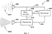
Фигура 5 - схематическое представление одного примерного варианта приемопередатчика в соответствии с настоящим изобретением.Figure 5 is a schematic representation of one exemplary embodiment of a transceiver in accordance with the present invention.
Фигура 6 - схематическое представление еще одного примерного варианта приемопередатчика в соответствии с настоящим изобретением.Figure 6 is a schematic representation of another exemplary embodiment of a transceiver in accordance with the present invention.
ПОДРОБНОЕ ОПИСАНИЕ ИЗОБРЕТЕНИЯDETAILED DESCRIPTION OF THE INVENTION
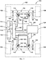
Обратимся теперь к чертежам, на которых показаны примерные варианты воплощения настоящего изобретения без его ограничения данным вариантом. На фигуре 1 показано транспортное средство 100, имеющее подрессоренную массу, такую, например, как кузов транспортного средства 102, и неподрессоренную массу, такую, например, как оси 104 и колеса 106. Между подрессоренной и неподрессоренной массами транспортного средства установлено множество демпфирующих элементов, например, амортизаторов 108, закрепленных соответствующим образом. Дополнительно, множество пневматических упругих элементов, например, блоков пневматической подвески 110 расположено между подрессоренной и неподрессоренной массами транспортного средства рядом с колесом 106 и амортизаторами 108.Turning now to the drawings, in which exemplary embodiments of the present invention are shown without limiting it to this embodiment. 1 shows a
Транспортное средство 100 также включает систему подачи сжатого газа 112, которая сообщается с блоками пневматической подвески 110 и оперативно выборочно подает в блоки подвески и выпускает из них сжатый газ. Система пневматической подвески 112 включает источник сжатого газа, например, компрессор 114, и может включать емкость для хранения газа, например, баллон 116 для приема и хранения сжатого газа, поступающего от источника сжатого газа. Система 112 может дополнительно включать подходящую систему выхлопа газа, например, глушитель 118 для вывода отработанных газов из системы.
Система пневматической подвески 112 может сообщаться с упругими элементами любым подходящим способом. Например, система 112 может включать клапан в сборе 120 или другое подходящее устройство или узел для выборочного распределения газа под давлением между источниками сжатого газа или источниками и упругими элементами. Как показано в примерном варианте воплощения изобретения на фигуре 1, компрессор 114, баллон 116 и глушитель 118 сообщаются по потоку газа с клапаном в сборе 120. Кроме того, блоки пневматической подвески 110 сообщаются по потоку газа с клапаном в сборе 120 через линии подачи газа 122. Таким образом, клапан в сборе 120 может быть выборочно открыт для подачи сжатого газа от компрессора и/или баллона к одному или нескольким бокам пневматической подвески. Кроме того, клапан в сборе 120 может быть выборочно открыт, чтобы выпустить газ под давлением из одного нескольких блоков пневматической подвески через глушитель 118 или другое подходящее устройство. Следует понимать, что описанная выше система пневматической подвески и ее работа являются просто примерами, и что любая другая подходящая среда под давлением, система и/или способ эксплуатации могут в равной мере использоваться в настоящем изобретении.The
Транспортное средство 100 также включает систему управления подвеской 124 для выборочного воздействия на один или несколько компонентов системы подвески, например, на амортизаторы 108, блоки пневматической подвески 110 и/или системы подачи сжатого газа 112. Система управления подвеской 124 включает электронное управляющее устройство 126, соединенное с одним или несколькими элементами клапана в сборе 120, например, через линию связи 128, для выборочного воздействия и/или эксплуатации этой подвески. Кроме того, электронное управляющее устройство 126 сообщается с блоками пневматической подвески 110 соответствующим способом, например, через линии связи 130.
Системы управления подвеской, такие как система управления 124, могут быть различными. Например, система управления 124 может использоваться для регулирования высоты (т.е. выборочно поднимать или опускать подрессоренную массу транспортного средства). В другом примере системы управления подвеской, например, в системе управления 124 могут использоваться для выравнивания (т.е. поддерживать подрессоренную массу транспортного средства, в основном, на определенном уровне). С учетом этой общей связи с контролем высоты и регулированием, в системе управления подвеской обычно используют один или несколько датчиков высоты или датчиков расстояния, чтобы контролировать высоту и/или ориентацию транспортного средства. Известны и широко используются различные датчики высоты и/или устройства индикации расстояния, как обсуждено в одном из предыдущих разделов этого описания. Как альтернативное устройство, блоки пневматической подвески 110 включают системы индикации расстояния в соответствии с настоящим изобретением, которые излучают электромагнитные волны 132 и 134, чтобы определить и сообщить данные о высоте транспортного средства или расстояния между двумя транспортными средствами и элементами системы подвески.Suspension control systems, such as
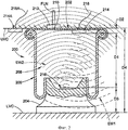
Один примерный вариант пневматического элемента подвески в соответствии с настоящим изобретением показан на фигуре 2 в виде блока пневматической подвески 200, который включает первый или верхний конечный элемент 202, второй или нижний конечный элемент 204, и гибкую упругую стенку 206, закрепленную между ними. Первый или верхний конечный элемент 202 на фигуре расположен вдоль соответствующего верхнего компонента транспортного средства, UVC и второй или нижний конечный элемент 204 расположен вдоль соответствующего нижнего компонента транспортного средства LVC. Верхние и нижние компоненты транспортного средства могут, например, быть частями подрессоренной и неподрессоренной масс транспортного средства или могут быть связаны с этими частями. Кроме того, следует отметить, что первый и второй конечные элементы могут быть соответственно закреплены на верхних и нижних компонентах транспортного средства любым подходящим способом, например, путем использования соединителей (не показаны). Кроме того, следует понимать, что блок пневматической подвески 200, показанный на фигуре 2, представляет собой конструкцию типа пневматической подвески с обкатывающей диафрагмой. Однако, понятно, что эта конструкция является просто примерной, и что любая другая подходящая конструкция может также быть использована.One exemplary embodiment of a pneumatic suspension element in accordance with the present invention is shown in FIG. 2 as an
Упругая стенка 206, по меньшей мере, частично определяет камеру пружины 208, расположенную между конечными элементами 202 и 204. Соответствующая линия FLN, как одна из линий 122 подачи газа под давлением на фигуре 1, например, сообщается с камерой пружины 208 через отверстие, выполненное в одном из конечных элементов блока пневматической подвески, в частности, канал 210, проходящий через первый конечный элемент 202. Подходящий соединитель или фитинг 212 могут использоваться, чтобы поддерживать рабочее сообщение линии подачи газа под давлением FLN с камерой пружины 208 по каналу 210.The
Блок пневматической подвески 200 также включает систему индикации расстояния (без номера позиции), которая содержит первый приемопередатчик 214 и второй приемопередатчик 216, расположенный на расстоянии D1 от первого приемопередатчика. Первый приемопередатчик 214 может сообщаться с одним или несколькими устройствами или элементами через токопроводящую нагрузку 218.The
Например, токопроводящая нагрузка 218 может быть элементом линии связи 130 на фигуре 1, проходящей между блоком пневматической подвески 110 и электронным управляющим устройством 126. Кроме того, электроэнергия может поступать от внешнего источника питания (не показан), например, от генератора переменного тока или от батареи транспортного средства. Однако, как показано на фигуре 2, второй приемопередатчик 216 является предпочтительно радиопередатчиком. Таким образом, связь со вторым приемопередатчиком 216 осуществляется, используя первую электромагнитную волну EW1 и вторую электромагнитную волну EW2.For example, the
В примерном варианте воплощения изобретения, показанном на фигуре 2, первый приемопередатчик 214 установлен на первом конечном элементе 202, а второй приемопередатчик 216 установлен на втором конечном элементе 204. Первый и второй приемопередатчики могут быть закреплены на конечных элементах любым подходящим способом, например, используя подходящие соединители, клей, кронштейны или интегрируя (например, сваркой) приемопередатчик или его компоненты с конечным элементом. Следует понимать, что такое устройство является просто примерным вариантом, и что любые компоненты системы индикации расстояния в соответствии с настоящим изобретением могут быть установлены в других положениях, ориентации и/или с помощью других устройств. Как показано на фигуре 2, первый и второй приемопередатчики могут использоваться в несогласованной ориентации. Так, в примерном варианте воплощения изобретения, показанном на фигуре 2, второй приемопередатчик 216 расположен приблизительно в центре на втором конечном элементе, тогда как первый приемопередатчик 214 расположен снаружи на внешней кромке первого конечного элемента. Точно так же первый приемопередатчик 214 может произвольно включать вторую часть 214А, которая монтируется отдельно от первой части и связана с одним или несколькими другими устройствами или элементами через токопроводящую нагрузку 218А. В таком устройстве первая часть может быть передающей частью, а вторая часть может быть приемной частью. Однако любая другая подходящая конфигурация, устройство или способ работы могут использоваться альтернативно. Кроме того, следует понимать, что расстояние D2 между первым приемопередатчиком 214 и первым конечным элементом 202, и расстояние D3 между вторым приемопередатчиком 216 и вторым конечным элементом 204, как правило, будет фиксированным расстоянием. Специалисты в данной области техники знают, что расстояние между приемопередатчиками, которое представлено как размер D1 на фигуре 2, может также представлять высоту блока пневматической подвески 200, обозначенную размером D4, и что другие размеры или расстояния могут быть определены аналогичным образом.In the exemplary embodiment shown in FIG. 2, the
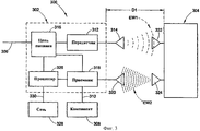
Один примерный вариант воплощения изобретения в виде системы индикации расстояния 300 схематично показан на фигуре 3 и включает первый приемопередатчик 302 и второй приемопередатчик 304, расположенный на расстоянии D1 от первого приемопередатчика 302. Первый приемопередатчик 302 соединен с подходящим внешним источником питания, таким как батарея или генератор переменного тока транспортного средства, например, через токопроводящую нагрузку 306. Кроме того, первый приемопередатчик 302 может быть соединен с одной или несколькими другими системами и/или элементами 308, например, через подходящую токопроводящую нагрузку 310.One exemplary embodiment of the invention as a
Первый приемопередатчик 302 включает передатчик 312 и первую антенну 314, соединенную с передатчиком. Соответственно, стабилизированное напряжение может быть подано на передатчик 312 от внешнего источника питания (не показан) через нагрузку 306. Альтернативно, первый приемопередатчик 302 может включать цепь питания 316, связанную с токопроводящей нагрузкой 306 для получения электрической энергии от подходящего источника питания. Цепь 316 может быть выходом кондиционированной электроэнергии соответствующего напряжения и/или тока для использования в работе других компонентов приемопередатчика 302. Например, цепь питания 316, показанная на фигуре 3, электрически соединенной с передатчиком 312, обеспечивает кондиционированную электроэнергию для этого передатчика. Передатчик 312 является рабочим и выдает 1 прямоугольный импульсный сигнал, который передается, как первая электромагнитная волна EW1, используя первую антенну 314.The
Приемопередатчик 302 также включает приемник 318, электрически соединенный с цепью питания 316, и вторую антенну 320, электрически соединенную с приемником 318. Второй приемопередатчик 304 включает первую рабочую антенну 322, которая получает первую электромагнитную волну EW1. Второй приемопередатчик также включает вторую рабочую антенну 324, которая передает вторую электромагнитную волну EW2, принимаемую второй антенной 320 первого приемопередатчика 302 и поступающую в приемник 318 этого приемопередатчика. Второй приемопередатчик 304 может формировать модулирующий сигнал, соответствующий входному сигналу, действующему на соединенные компоненты системы индикации расстояния, такие как конструкционные компоненты, на которых крепится второй приемопередатчик, и использовать модулирующий сигнал для формирования такой характеристики, как частота или амплитуда второй электромагнитной волны EW2. Приемник оперативно извлекает модулирующий сигнал из второй электромагнитной волны и формирует выходной сигнал, передаваемый на другие устройства и/или системы подходящим способом, например, компоненты или устройства 308 через токопроводящую нагрузку 310. Альтернативно, первый приемопередатчик 302 может включать процессор 326, соединенный с цепью питания 316, которая обеспечивает кондиционированную электроэнергию. Кроме того, процессор 326 находится в электрической связи с приемником 318 и может получать сформированный таким образом выходной сигнал. Процессор может затем декодировать или транслировать выходной сигнал как данные и/или другую информацию, например данные, связанные с расстоянием, значением ускорения, уровнем температуры, уровнем давления или другие входные параметры. Данные и/или другая информация могут быть переданы на другие устройства или системы, например, в систему или сеть транспортного средства 328, например, через токопроводящую нагрузку 330.The
При работе первая электромагнитная волна EW1 передается от первого приемопередатчика 302, используя первую антенну 314, и принимается первой антенной 322 второго приемопередатчика 304. В одном примерном варианте воплощения изобретения первая антенна 322 второго приемопередатчика 304 включает индуктивный элемент (не показан) или другую подходящую цепь или компонент, и первая электромагнитная волна EW1 формирует электрический выход поперек или вдоль этого индуктивного элемента, чтобы обеспечивать электропитание второго приемопередатчика 304. Альтернативно, второй приемопередатчик 304 может быть подключен к отдельному источнику электроэнергии, вместо того чтобы использовать индуктивное соединение с первым приемопередатчиком 302. специалисты в данной области техники знают, что свойства электромагнитных волн меняются в зависимости от расстояния, пройденного электромагнитной волной, по известным зависимостям. Таким образом, используя подходящие вычисления, устройства или сравнение, расстояние, пройденное первой электромагнитной волной EW1 (т.е. расстояние D1 между первым и вторым приемопередатчиками), может быть определено вторым приемопередатчиком и передано первому приемопередатчику или другому компоненту. Альтернативно, сигнал, соответствующий расстоянию, пройденному первой электромагнитной волной EW1, и/или другие данные или информация могут быть переданы со второго приемопередатчика на подходящее устройство или компоненты для приема волны EW1 и определения расстояния и/или других данных или информации. Такие подходящие компоненты могут включать, например, приемник 318 и/или процессор 326 первого приемопередатчика.In operation, the first electromagnetic wave EW1 is transmitted from the
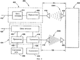
Другой примерный вариант системы индикации расстояния 400 показан на фигуре 4 и включают передающую часть 402, приемную часть 404 и приемопередатчик 406. Передающая часть 402 содержит передатчик 408 и антенну 410, соединенную с передатчиком, который оперативно формирует прямоугольный импульсный сигнал, который передается как первая электромагнитная волна EW1, используя антенну 410. Передатчик 408 может получать кондиционированную электроэнергию от внешнего источника питания через подходящую токопроводящую нагрузку, например, нагрузку 412. Альтернативно, передающая часть 402 может включать цепь питания 414, которая получает электроэнергию от внешнего источника питания и обеспечивает выход электроэнергии для передатчика 408.Another exemplary embodiment of the
Приемная часть 404 включает приемник 416 и антенну 418, электрически соединенную с приемником 416. Кондиционированная электроэнергия может быть получена от внешнего источника электроэнергии через токопроводящую нагрузку, например, нагрузку 420. Альтернативно, цепь питания 422 может быть включена в приемную часть 404, которая может получать электроэнергию от внешнего источника питания и подавать кондиционированную электроэнергию на приемник.The receiving
Приемник 416, показанный на фигуре 4, электрически соединен с компонентом или устройством 424 через токопроводящую нагрузку 426, и принимает поступающие на него сигналы. Альтернативно, процессор 428 может быть включен в приемную часть 404, которая электрически соединена с цепью питания 422 и приемником 416. Процессор 428, если он предусмотрен, может обрабатывать поступающие выходные данные, сигналы и/или другую информацию для других компонентов или систем, таких как транспортное средство или системная сеть 430, например, через подходящее устройство соединения, например, через токопроводящую нагрузку 432. Приемопередатчик 406, показанный на фигуре 4, расположен на расстоянии D1 от передающей части 402. В этом случае первая электромагнитная волна EW1 проходит расстояние D1 и принимается первой антенной 434 приемопередатчика 406. Приемопередатчик 406 принимает вторую электромагнитную волну EW2 от второй антенны 436. Электромагнитная волна EW2 модулирована для передачи сигналов, данных и/или другой информации, передаваемых приемной части 404, способом, подобным обсужденному способу выше по отношению к системе индикации расстояния 300. Система 400 отличается от системы индикации расстояния 300, однако, в этой конструкции приемная часть 404 может быть установлена и закреплена отдельно от передающей части 402. Вместе с тем, приемная часть 404 расположена на расстоянии D5 от приемопередатчика 406, которое больше расстояния D1. Однако следует понимать, что расстояние D5 является просто репрезентативным расстоянием, которое может отличаться от расстояния D1, и что таким образом может быть представлено расстояние больше или меньше, чем расстояние D1.A
Один примерный вариант приемопередатчика, например, в виде приемопередатчиков 216, 304 и 406, которые, соответственно, показаны и обсуждены на фигурах 2-4, показан на фигуре 5 как приемопередатчик 500, который включает первую антенну 502 и вторую антенну 504. Первая антенна 502 оперативно принимает первую электромагнитную волну EW1 и может включать индуктивный элемент (не показан) или другое подходящее устройство или компоненты. Первая электромагнитная волна EW1 формирует электрический сигнал поперек или вдоль этого индуктивного элемента для подачи электроэнергии на приемопередатчик. Приемопередатчик 500 также включает цепь питания 506, электрически связанную с первой антенной 502. Цепь питания 506 может функционировать для подачи электрической энергии, передаваемой поперек или вдоль антенны 502 первой электромагнитной волной EW1. Альтернативно, может быть использован отдельный источник питания, например батарея (не показана). Процессор 508 электрически соединен с антенной 502 и цепью питания 506 через электрические провода 510 и 512, соответственно. Цепь питания 506 служит для подачи питания на процессор, что, соответственно, является условием для его работы. Кроме того, электрический сигнал с антенны 502 подается в процессор 508 по электрическому проводу 510, и с выхода процессора модулирующий сигнал передается на передатчик 514 по электрическому проводу 516. В одном примерном варианте воплощения изобретения выход сигнала модуляции процессором зависит от расстояния между устройством или компонентом, который передает первую электромагнитную волну (например, приемопередатчик 302 или часть передатчика 402) и приемопередатчик 500. Цепь питания 506 также соединена с передатчиком 514 электрическим проводом 518 и подает электроэнергию к этому передатчику. Передатчик 514 оперативно формирует прямоугольный импульсный сигнал и объединяет прямоугольный импульсный сигнал с модулирующим сигналом от процессора 508 для передачи второй электромагнитной волны EW2, используя вторую антенну 504.One exemplary embodiment of a transceiver, for example, in the form of
В одном примерном варианте воплощения изобретения, процессор 508 может быть использован для передачи или преобразования электрического сигнала, полученного из антенны 502, в модулирующий сигнал, изменяемый по амплитуде и/или по частоте, в котором изменения в амплитуде и/или частоте соответствуют уровню напряжения или тока электрического сигнала, поступающего из антенны. Следует отметить, что уровень напряжения и/или тока электрического сигнала, поступающего из антенны, будет изменяться в зависимости от расстояния, пройденного первой электромагнитной волной, которое соответствует расстоянию между приемопередатчиками или другими элементами. Таким образом, измерение расстояния может быть передано, как изменение по частоте и/или по амплитуде электромагнитной волны. Следовательно, электромагнитная волна EW2 модулирована по расстоянию между первым и вторым приемопередатчиками. Модулированная электромагнитная волна может быть получена приемным устройством или компонентами, например, первым приемопередатчиком 302 или приемной частью 404, которая может извлечь модулирующий сигнал и передать его на различные компоненты или системы, которые могут определить расстояние на основе этого сигнала. Альтернативно, приемное устройство или компоненты могут преобразовать модулирующий сигнал или иным образом определить расстояние на основе модуляции второй электромагнитной волны EW2 и выходные данные и/или информацию, соответствующую этому расстоянию.In one exemplary embodiment of the invention, the
Одним примером подходящего устройства для использования в качестве процессора 508 является управляемый генератор или преобразователь напряжение-частота, который оперативно обеспечивает выход переменной частоты в ответ на изменения входного напряжения. Подходящий преобразователь напряжение-частота поставляется Национальной полупроводниковой корпорацией, Санта-Клара, Калифорния под обозначение продукта LM231AN.One example of a suitable device for use as a
Другим примерным вариантом воплощения изобретения являются приемопередатчики 216, 304, 406 и 500, которые показаны и обсуждены на фигурах 2-5. На фигуре 6 показан приемопередатчик 600, который включает первую антенну 602 и вторую антенну 604. Приемопередатчик 600 также включает цепь питания 606, электрически связанную с антенной 602, и служит для сбора электрической энергии, наведенной в первой антенне, как подробно обсуждено выше. Процессор 608 подключен к цепи питания 606 через электрические провода 610 и получает электрическую энергию, которая, соответственно, обеспечивает работу этого устройства. Первый датчик 612 включен между антенной 602 и процессором 608 с помощью проводов 614 и 616. В одном примерном варианте воплощения изобретения датчик 612 реагирует на выходной сигнал, связанный с расстоянием, пройденным первой электромагнитной волной EW1, как обсуждено выше, и передает выходной сигнал на процессор 608. Аналогично процессору 508 в приемопередатчике 500, первый датчик 612 может оперативно изменять частоту и/или амплитуду выходного сигнала в ответ на изменения напряжения и/или тока от антенны 602 по проводу 614. Альтернативно, в качестве датчика 612 может использоваться аналого-цифровой преобразователь или другое подходящее устройство, которое получает входной сигнал с провода 614 и передает цифровой выходной сигнал на процессор 608 по проводу 616. Точно так же процессор 608 может включать другое устройство, например, программируемый микропроцессор, микроконтроллер или микрокомпьютер, который способен принимать цифровой сигнал от датчика и формировать модулирующий сигнал, соответствующий расстоянию, пройденному первой электромагнитной волной.Another exemplary embodiment of the invention are
Процессор выдает модулирующий сигнал на передатчик 618 через электрический провод 620. Передатчик 618 электрически связан с цепью питания 606 через электрический провод 622. Передатчик формирует второй прямоугольный импульсный сигнал и объединяет его с модулирующим сигналом, чтобы создать вторую модулированную электромагнитную волну EW2, которая передается второй антенной 604.The processor provides a modulating signal to the
В одном примерном варианте воплощения изобретения приемопередатчик 600 может также включать один или несколько дополнительных компонентов, таких как датчики 614 и 616. Следует отметить, что могут быть использованы компоненты любого подходящего числа, типа и/или вида, например, датчики, реагирующие на выходные сигналы, датчики, указывающие входной сигнал, действующий на другую часть или компоненты, например, датчики ускорения, давления или температуры. Как показано на фигуре 5, датчик 614 включен между цепью питания 606 и процессором 608 через токопроводящие элементы 628 и 630. Кроме того, датчик 616 является электропроводным элементом между цепью питания и процессором через токопроводящие элементы 632 и 634. Примеры подходящих датчиков включают, например, акселерометры; датчики температуры, например, термопары, и датчики давления.In one exemplary embodiment, the transceiver 600 may also include one or more additional components, such as
Если используются дополнительные компоненты, например, датчики 624 и/или 626, то процессор 608 предпочтительно будет оперативно получать выходные сигналы от этих компонентов, так же как и от датчика 612. Процессор может затем передавать сигналы или данные и/или информацию соответствующему приемному устройству или компоненту. Один подходящий пример включает процессор 608, объединяющий или кодирующий различные выходные сообщения и формирующий модулирующий сигнал для передачи данных и/или информации от датчиков или других компонентов. Альтернативно могут использоваться схемы кодирования сигнала, причем такое кодирование осуществляется со сдвигом частот, например, фазовая манипуляция. Затем передатчик 612 модулирует несущую, используя модулирующий сигнал и данные и/или информацию для передачи первому приемопередатчику, используя вторую электромагнитную волну EW2, как обсуждено выше. После этого первый приемопередатчик или приемная часть может извлечь и декодировать модулирующий сигнал как выходной сигнал, данные и/или информацию, полученную от нескольких датчиков. Первая электромагнитная волна EW1 и вторая электромагнитная волна EW2, соответственно, основаны на первом и втором прямоугольных сигналах с немодулированной несущей. Прямоугольные импульсные сигналы с немодулированной несущей могут быть сформированы любым подходящим способом, и одним примерным вариантом является их формирование соответствующим передатчиком. Например, первый прямоугольный импульсный сигнал может быть сформирован передатчиком 312 или 408. Точно так же второй прямоугольный импульсный сигнал может быть сформирован передатчиком 514 или 618. Следует отметить, что для сигналов несущей могут использоваться любые подходящие свойства и/или характеристики. Например, сигналы несущей могут передаваться на любой подходящей частоте, например, от примерно 20 кГц до примерно 30 ГГц. В одном примерном варианте воплощения изобретения первая электромагнитная волна EW1 основана на первом сигнале несущей, имеющем частоту в диапазоне от примерно 30 кГц до примерно 300 МГц. Кроме того, такой примерный вариант воплощения изобретения включает вторую электромагнитную волну EW2, на основе второго сигнала несущей, имеющего частоту в диапазоне от примерно 300 кГц до примерно 6 ГГц. Однако следует понимать, что альтернативно могут использоваться любая подходящая частота или диапазон частот.If additional components are used, for example,
Хотя настоящее изобретение было описано на конкретных примерах его реализации, и значительное внимание было здесь уделено структурным взаимосвязям между компонентами, следует понимать, что могут быть сделаны различные изменения и модификации в показанных на чертежах и описанных вариантах воплощения изобретения, не выходя из духа и объема изобретения. Соответственно, настоящее описание должно быть интерпретировано просто как пример, а не ограничение настоящего изобретения. Точно так же следует понимать, что все такие модификации и изменения являются частью настоящего изобретения, объем которого определяется формулой изобретения.Although the present invention has been described with specific examples of its implementation, and considerable attention has been paid here to the structural relationships between the components, it should be understood that various changes and modifications can be made to the embodiments shown in the drawings and described embodiments without departing from the spirit and scope of the invention . Accordingly, the present description should be interpreted merely as an example, and not a limitation of the present invention. In the same way, it should be understood that all such modifications and changes are part of the present invention, the scope of which is defined by the claims.
Claims (12)
передатчик, расположенный рядом с первым конечным элементом и служащий для передачи первой электромагнитной волны;
приемопередатчик, расположенный рядом со вторым конечным элементом на определенном расстоянии от указанного передатчика, при этом приемопередатчик получает указанную первую электромагнитную волну и передает вторую электромагнитную волну, при этом приемопередатчик модулирует указанную вторую электромагнитную волну относительно указанного расстояния, и
приемник, расположенный отдельно от приемопередатчика и используемый для приема указанной второй модулированной электромагнитной волны.1. A distance indication system for a vehicle suspension system, which includes an air suspension unit with first and second end elements and an elastic wall located between them, wherein the distance indication system comprises
a transmitter located adjacent to the first final element and serving to transmit the first electromagnetic wave;
a transceiver located next to the second end element at a certain distance from the specified transmitter, wherein the transceiver receives said first electromagnetic wave and transmits a second electromagnetic wave, wherein the transceiver modulates said second electromagnetic wave with respect to said distance, and
a receiver located separately from the transceiver and used to receive the specified second modulated electromagnetic wave.
первый конечный элемент;
второй конечный элемент, расположенный на расстоянии от указанного первого конечного элемента;
упругую стенку, установленную между первым и вторым конечными элементами и, по меньшей мере, частично формирующую воздушную камеру между ними;
первый приемопередатчик, закрепленный на указанном первом конечном элементе, при этом первый приемопередатчик имеет первую антенну, служащую для передачи первой электромагнитной волны, и вторую антенну, используемую для приема второй электромагнитной волны, и
второй приемопередатчик, закрепленный на указанном втором конечном элементе на определенном расстоянии от первого приемопередатчика, при этом второй приемопередатчик имеет первую антенну, служащую для приема указанной первой электромагнитной волны, вторую антенну, служащую для передачи указанной второй электромагнитной волны, и процессор, включенный между указанными первой и второй антеннами, который получает электрический сигнал, относящийся к расстоянию, от первой антенны второго приемопередатчика, и модулирующий характеристику второй электромагнитной волны относительно указанного электрического сигнала.7. The air suspension unit containing
first finite element;
a second finite element located at a distance from the specified first finite element;
an elastic wall mounted between the first and second end elements and at least partially forming an air chamber between them;
a first transceiver mounted on said first terminal element, wherein the first transceiver has a first antenna serving to transmit the first electromagnetic wave, and a second antenna used to receive the second electromagnetic wave, and
the second transceiver mounted on the specified second end element at a certain distance from the first transceiver, while the second transceiver has a first antenna used to receive the specified first electromagnetic wave, a second antenna used to transmit the specified second electromagnetic wave, and a processor connected between the first and a second antenna, which receives an electrical signal related to the distance from the first antenna of the second transceiver, and a modulating characteristic the second electromagnetic wave relative to the specified electrical signal.
(a) использование передатчика, который крепится рядом с первым конечным элементом и передачу первой электромагнитной волны;
(b) использование приемопередатчика, который устанавливается на расстоянии от передатчика рядом со вторым конечным элементом и служит для передачи второй электромагнитной волны;
(c) формирование электрического сигнала в указанном приемопередатчике, используя указанную первую электромагнитную волну;
(d) модуляцию указанной второй электромагнитной волны по расстоянию между передатчиком и приемопередатчиком, и
(е) определение расстояния между передатчиком и приемопередатчиком на основе второй модулированной электромагнитной волны.10. A method for determining the distance between the first and second end elements of an air suspension, comprising the following stages:
(a) using a transmitter that is mounted next to the first end element and transmitting the first electromagnetic wave;
(b) the use of a transceiver that is installed at a distance from the transmitter near the second end element and serves to transmit a second electromagnetic wave;
(c) generating an electrical signal in said transceiver using said first electromagnetic wave;
(d) modulating said second electromagnetic wave with respect to the distance between the transmitter and the transceiver, and
(e) determining a distance between the transmitter and the transceiver based on a second modulated electromagnetic wave.
Applications Claiming Priority (2)
| Application Number | Priority Date | Filing Date | Title |
|---|---|---|---|
| US11/337,746 US7420462B2 (en) | 2006-01-23 | 2006-01-23 | Air spring distance indicating system and method |
| US11/337,746 | 2006-01-23 |
Publications (2)
| Publication Number | Publication Date |
|---|---|
| RU2008134330A RU2008134330A (en) | 2010-02-27 |
| RU2407655C2 true RU2407655C2 (en) | 2010-12-27 |
Family
ID=37964636
Family Applications (1)
| Application Number | Title | Priority Date | Filing Date |
|---|---|---|---|
| RU2008134330/11A RU2407655C2 (en) | 2006-01-23 | 2007-01-19 | System and method of distance indication |
Country Status (8)
| Country | Link |
|---|---|
| US (2) | US7420462B2 (en) |
| EP (1) | EP1991432B1 (en) |
| JP (1) | JP2009524062A (en) |
| CN (1) | CN101405156B (en) |
| AU (1) | AU2007208409B2 (en) |
| HK (1) | HK1128261A1 (en) |
| RU (1) | RU2407655C2 (en) |
| WO (1) | WO2007087235A1 (en) |
Families Citing this family (31)
| Publication number | Priority date | Publication date | Assignee | Title |
|---|---|---|---|---|
| GB2406548A (en) * | 2003-10-03 | 2005-04-06 | Trelleborg Ab | Air suspension system |
| US7894473B2 (en) * | 2006-04-12 | 2011-02-22 | Honeywell International Inc. | System and method for monitoring valve status and performance in a process control system |
| US7643796B2 (en) * | 2006-04-12 | 2010-01-05 | Honeywell International Inc. | System and method for process control using wireless devices with multiple transceivers and at least one process element |
| US7733239B2 (en) * | 2006-05-08 | 2010-06-08 | Bfs Diversified Products, Llc | Distance determining system and method |
| US8160774B2 (en) * | 2008-10-15 | 2012-04-17 | GM Global Technology Operations LLC | Vehicular actuator system |
| US8174377B2 (en) * | 2008-11-14 | 2012-05-08 | GM Global Technology Operations LLC | Suspension height sensor |
| US8175770B2 (en) * | 2008-11-17 | 2012-05-08 | GM Global Technology Operations LLC | Height sensing system for a vehicular suspension assembly |
| US9219956B2 (en) | 2008-12-23 | 2015-12-22 | Keyssa, Inc. | Contactless audio adapter, and methods |
| US9191263B2 (en) * | 2008-12-23 | 2015-11-17 | Keyssa, Inc. | Contactless replacement for cabled standards-based interfaces |
| SE533463C2 (en) * | 2009-02-26 | 2010-10-05 | Stroemsholmen Ab | Balancing device for balancing two relatively moving parts including a gas spring and method for balancing |
| US8063498B2 (en) * | 2009-02-27 | 2011-11-22 | GM Global Technology Operations LLC | Harvesting energy from vehicular vibrations |
| US8253281B2 (en) * | 2009-02-27 | 2012-08-28 | GM Global Technology Operations LLC | Energy harvesting apparatus incorporated into shock absorber |
| US7936113B2 (en) * | 2009-02-27 | 2011-05-03 | GM Global Technology Operations LLC | Harvesting energy from vehicular vibrations using piezoelectric devices |
| US8143766B2 (en) * | 2009-02-27 | 2012-03-27 | GM Global Technology Operations LLC | Harvesting energy from vehicular vibrations using piezoelectric devices |
| US7956797B2 (en) * | 2009-03-09 | 2011-06-07 | GM Global Technology Operations LLC | System and method for measuring a relative distance between vehicle components using ultra-wideband techniques |
| CN101905694B (en) * | 2009-06-04 | 2012-12-26 | 品秀橡胶股份有限公司 | Intelligent electronic suspension system capable of adjusting air pressure automatically |
| US8614518B2 (en) * | 2009-10-14 | 2013-12-24 | GM Global Technology Operations LLC | Self-powered vehicle sensor systems |
| US8905071B2 (en) | 2010-10-26 | 2014-12-09 | Air Lift Company | Integrated manifold system for controlling an air suspension |
| DE102012213697A1 (en) * | 2012-08-02 | 2014-02-06 | Robert Bosch Gmbh | Sensor device and method for determining a pressure of a medium located within an electrochemical energy store, electrochemical energy store and method for producing the same |
| DE102013215360B4 (en) * | 2012-09-10 | 2015-09-10 | Ford Global Technologies, Llc | Height adjustment device for vehicles with air spring and vibration damper |
| EP2724877B1 (en) * | 2012-10-29 | 2019-03-20 | ContiTech USA, Inc. | Air spring with a sensor arrangement |
| EP2728217B1 (en) * | 2012-11-02 | 2019-08-21 | ContiTech USA, Inc. | Air spring height measurement arrangement |
| JP6345450B2 (en) * | 2014-03-14 | 2018-06-20 | 住友電気工業株式会社 | Air spring |
| DE102015002167A1 (en) * | 2015-02-24 | 2016-08-25 | Wabco Gmbh | Method and system for altitude measurement in a vehicle |
| DE102016218603A1 (en) * | 2016-09-27 | 2018-03-29 | Jost-Werke Deutschland Gmbh | Device for detecting the position of a first or second vehicle to be coupled together |
| TWI801389B (en) | 2017-06-16 | 2023-05-11 | 澳洲商巴斯空氣管理有限公司 | Air management system for vehicle and air pressure adjustment method thereof, leveling valve, method for controlling vehicle stability, vehicle suspension system and cross-flow system of vehicle |
| US10220665B2 (en) | 2017-06-16 | 2019-03-05 | BASE Air Management, Inc. | Symmetrically dynamic equalized volume and pressure air management system |
| CN111683828A (en) | 2017-10-17 | 2020-09-18 | 基航管理有限公司 | Symmetrical dynamic equalization of volumetric and pressure air management systems |
| EP3697632A4 (en) * | 2017-10-19 | 2021-07-21 | SAF-Holland, Inc. | Dynamic heavy-duty vehicle suspension arrangement |
| EP3849831A1 (en) * | 2018-09-13 | 2021-07-21 | Firestone Industrial Products Company, LLC | Communication modules as well as gas spring assemblies and vehicle systems including same |
| DE102021214579A1 (en) * | 2021-12-17 | 2023-06-22 | Contitech Ag | air spring arrangement |
Family Cites Families (79)
| Publication number | Priority date | Publication date | Assignee | Title |
|---|---|---|---|---|
| US3780370A (en) | 1971-03-11 | 1973-12-18 | Brown & Root | Electronic range measuring method and apparatus |
| US3859624A (en) | 1972-09-05 | 1975-01-07 | Thomas A Kriofsky | Inductively coupled transmitter-responder arrangement |
| JPS5916229B2 (en) | 1972-09-26 | 1984-04-13 | クリスチアン ハイゲン ラボラトリウム ビ− ブイ | Data transfer method and device between two stations |
| GB1511354A (en) | 1975-05-07 | 1978-05-17 | Nat Res Dev | Distance measuring apparatus |
| US4183022A (en) | 1976-06-03 | 1980-01-08 | Electronique Marcel Dassault | Transponder for radiocommunication system, particularly for measuring the distance between two stations |
| US4041490A (en) | 1976-06-25 | 1977-08-09 | Cubic Corporation | Measurement system calibrated to be insensitive to temperature variation induced changes in internal phase shifts present in the system |
| US4307397A (en) | 1977-12-05 | 1981-12-22 | The South African Inventions Development Corporation | Method of and apparatus for measuring distance |
| US4278977A (en) | 1979-05-04 | 1981-07-14 | Rca Corporation | Range determining system |
| US4646092A (en) | 1982-06-07 | 1987-02-24 | Plessey South Africa Limited | Method of and apparatus for continuous wave electromagnetic distance measurement of positioning |
| JPS60121130A (en) | 1983-12-06 | 1985-06-28 | Nissan Motor Co Ltd | Vehicle travel control device |
| DE3423602A1 (en) | 1984-06-27 | 1986-01-09 | Robert Bosch Gmbh, 7000 Stuttgart | Device for measuring the distance between the chassis and the axle of a vehicle |
| FR2574188B1 (en) | 1984-11-30 | 1987-02-27 | Inst Selskokhozyaistvennogo | METHOD FOR MEASURING THE DISTANCE UP TO A CONTROLLED TOOL CARRIER TRACTOR AND DEVICE FOR CARRYING OUT SAID METHOD |
| GB8516765D0 (en) | 1985-07-02 | 1985-08-07 | Dunlop Ltd | Suspension systems |
| SE456118B (en) | 1985-12-12 | 1988-09-05 | Stiftelsen Inst Mikrovags | PROCEDURE AND DEVICE FOR MEASURING DISTANCE BETWEEN A SUBSTANCE AND ANOTHER FORM WITH SIGNALS OF MICROWAVE FREQUENCY |
| US4757315A (en) | 1986-02-20 | 1988-07-12 | The United States Of America As Represented By The Administrator Of The National Aeronautics And Space Administration | Method and apparatus for measuring distance |
| DE3614744C2 (en) * | 1986-04-30 | 1994-11-10 | Koenig & Bauer Ag | Device for controlling a rotary printing machine |
| US4739328A (en) | 1986-07-14 | 1988-04-19 | Amtech Corporation | System for identifying particular objects |
| US4737705A (en) | 1986-11-05 | 1988-04-12 | Caterpillar Inc. | Linear position sensor using a coaxial resonant cavity |
| US4817922A (en) | 1987-10-23 | 1989-04-04 | The Goodyear Tire & Rubber Company | Airspring height sensor |
| US4798369A (en) * | 1987-11-03 | 1989-01-17 | The Firestone Tire & Rubber Company | Ultrasonic air spring system |
| US5701121A (en) | 1988-04-11 | 1997-12-23 | Uniscan Ltd. | Transducer and interrogator device |
| US4939328A (en) * | 1988-12-23 | 1990-07-03 | Judco Manufacturing, Incorporated | Quiet switching apparatus and method of operation |
| US5285189A (en) | 1991-05-14 | 1994-02-08 | Epic Technologies, Inc. | Abnormal tire condition warning system |
| US5266926A (en) | 1991-05-31 | 1993-11-30 | Avid Marketing, Inc. | Signal transmission and tag power consumption measurement circuit for an inductive reader |
| US6738697B2 (en) | 1995-06-07 | 2004-05-18 | Automotive Technologies International Inc. | Telematics system for vehicle diagnostics |
| JP3069408B2 (en) | 1991-08-09 | 2000-07-24 | 株式会社ブリヂストン | Height sensor and air spring |
| JP3187496B2 (en) | 1992-01-09 | 2001-07-11 | スタンレー電気株式会社 | Height sensor and air spring |
| US5570086A (en) | 1992-02-18 | 1996-10-29 | Citizen Watch Co., Ltd. | Data carrier system |
| US5373445A (en) * | 1992-03-05 | 1994-12-13 | Ford Motor Company | Method and apparatus for determining dynamic force within an air spring suspension |
| US5298904A (en) | 1992-08-04 | 1994-03-29 | Olich Kirk J | Distance measuring system |
| US5450088A (en) | 1992-11-25 | 1995-09-12 | Texas Instruments Deutschland Gmbh | Transponder arrangement |
| EP0650074A1 (en) | 1993-10-22 | 1995-04-26 | Texas Instruments Holland B.V. | Highly accurate RF-ID positioning system |
| JPH07181254A (en) | 1993-12-22 | 1995-07-21 | Hitachi Constr Mach Co Ltd | Safety system of construction machine |
| US5552789A (en) | 1994-02-14 | 1996-09-03 | Texas Instruments Deutschland Gmbh | Integrated vehicle communications system |
| DE4413341C2 (en) | 1994-04-18 | 1999-08-26 | Continental Ag | Measuring device with a magnetic field sensor for contactless detection of the clear distance between two components and their use |
| US5500065A (en) | 1994-06-03 | 1996-03-19 | Bridgestone/Firestone, Inc. | Method for embedding a monitoring device within a tire during manufacture |
| US5731754A (en) | 1994-06-03 | 1998-03-24 | Computer Methods Corporation | Transponder and sensor apparatus for sensing and transmitting vehicle tire parameter data |
| US5550536A (en) | 1994-08-17 | 1996-08-27 | Texas Instruments Deutschland Gmbh | Circuit frequency following technique transponder resonant |
| JPH0962816A (en) | 1994-10-06 | 1997-03-07 | Mitsubishi Electric Corp | Non-contact ic card and non-contact ic card system including the same |
| US5589821A (en) | 1994-12-13 | 1996-12-31 | Secure Technologies, Inc. | Distance determination and alarm system |
| US5707045A (en) | 1996-09-05 | 1998-01-13 | Bridgestone/Firestone, Inc. | Air spring system having an integral height sensor |
| DE19648112C1 (en) * | 1996-11-21 | 1998-03-05 | Contitech Luftfedersyst Gmbh | Device for contactless distance measurement |
| DE19701530C1 (en) | 1997-01-17 | 1998-08-06 | Contitech Luftfedersyst Gmbh | Axial distance determination between end members of compressed gas spring for vehicle |
| US5859692A (en) | 1997-05-16 | 1999-01-12 | Rochester Gauges, Inc. | Height sensor and air spring apparatus incorporating the same in the air chamber |
| US6036179A (en) * | 1997-12-22 | 2000-03-14 | Bridgestone/Firestone, Inc. | Air spring containing an active device and a suspension assembly and method using |
| US6122329A (en) | 1998-02-06 | 2000-09-19 | Intermec Ip Corp. | Radio frequency identification interrogator signal processing system for reading moving transponders |
| DE19820877C2 (en) * | 1998-05-09 | 2002-09-19 | Contitech Luftfedersyst Gmbh | Non-contact distance and pressure measurement within an air spring |
| US6111536A (en) | 1998-05-26 | 2000-08-29 | Time Domain Corporation | System and method for distance measurement by inphase and quadrature signals in a radio system |
| JP3916328B2 (en) | 1998-07-27 | 2007-05-16 | ローム株式会社 | Contactless communication system |
| US6249673B1 (en) | 1998-11-09 | 2001-06-19 | Philip Y. W. Tsui | Universal transmitter |
| US6309494B1 (en) | 1998-12-04 | 2001-10-30 | Bridgestone/Firestone Research, Inc. | Method of attaching sensitive electronic equipment to the inner surface of a tire |
| US6356738B1 (en) | 1999-02-18 | 2002-03-12 | Gary W. Schneider | Method and apparatus for communicating data with a transponder |
| FR2792134B1 (en) | 1999-04-07 | 2001-06-22 | St Microelectronics Sa | DISTANCE DETECTION BETWEEN AN ELECTROMAGNETIC TRANSPONDER AND A TERMINAL |
| IL129651A (en) | 1999-04-28 | 2004-08-31 | Nexense Ltd | High-precision measuring method and apparatus |
| US6474380B1 (en) | 1999-04-29 | 2002-11-05 | Bridgestone/Firestone North American Tire, Llc | Pneumatic tire and monitoring device including dipole antenna |
| US6414626B1 (en) | 1999-08-20 | 2002-07-02 | Micron Technology, Inc. | Interrogators, wireless communication systems, methods of operating an interrogator, methods of operating a wireless communication system, and methods of determining range of a remote communication device |
| AU2001257414A1 (en) | 2000-05-01 | 2001-11-12 | Isc/Us, Inc. | Data capture and logging with passive rf transmission |
| US6469590B1 (en) | 2000-06-20 | 2002-10-22 | Shakespeare Company | Marine antenna with an integral filter |
| JP2004502177A (en) | 2000-06-27 | 2004-01-22 | シーメンス アクチエンゲゼルシヤフト | Method for measuring the distance between two objects, and for controlling access control to an object or for controlling the use of an object, especially an access control and travel authentication device for a motor vehicle |
| WO2002029435A1 (en) | 2000-10-04 | 2002-04-11 | Siemens Aktiengesellschaft | Method and device for the wireless measurement of a movement of at least one object |
| DE10051825A1 (en) | 2000-10-19 | 2002-04-25 | Contitech Luftfedersyst Gmbh | Motor vehicle air spring system with ultrasound measuring arrangement |
| WO2002039314A1 (en) | 2000-11-13 | 2002-05-16 | Bridgestone/Firestone North American Tire, Llc | Wheel assembly identification device |
| JP4152595B2 (en) | 2001-01-11 | 2008-09-17 | 横浜ゴム株式会社 | Transponder and its system |
| ITTO20010035A1 (en) | 2001-01-19 | 2002-07-19 | Comau Systems Spa | PROCEDURE AND SYSTEM FOR MEASURING THE DISTANCE OF A MOBILE BODY FROM A FIXED PART. |
| JP3461498B2 (en) * | 2001-03-01 | 2003-10-27 | 徹志 上保 | Distance measuring device, distance measuring equipment and distance measuring method |
| DE10126087A1 (en) | 2001-05-29 | 2002-12-05 | Sick Ag | Distance determination method and device |
| CA2447898C (en) | 2001-06-01 | 2007-05-22 | The Boler Company | Radio frequency-controlled axle/suspension lift system |
| DE10151593A1 (en) * | 2001-10-18 | 2003-04-30 | Contitech Luftfedersyst Gmbh | Air spring interior space pressure determining method for motor vehicle, involves providing ultrasonic pulse measuring arrangement with transmitter circuit, transducer with adaption layer of fixed constant, and reflector |
| DE10155251A1 (en) | 2001-11-09 | 2003-06-18 | Siemens Ag | Transponder system and method for distance measurement |
| US7139581B2 (en) | 2002-05-02 | 2006-11-21 | Aeroscout, Inc. | Method and system for distance measurement in a low or zero intermediate frequency half-duplex communications loop |
| US6963301B2 (en) | 2002-08-19 | 2005-11-08 | G-Track Corporation | System and method for near-field electromagnetic ranging |
| DE10253278B4 (en) | 2002-11-15 | 2009-10-08 | Continental Automotive Gmbh | Tire measurement with an energy self-modulated backscatter transponder |
| DE10325396A1 (en) | 2003-05-28 | 2004-12-23 | Atmel Germany Gmbh | Circuit arrangement for phase modulation for backscatter-based transponder has control unit that can selectively connect voltage sources to varactor connection(s) depending on desired phase angle |
| JP2005092343A (en) * | 2003-09-12 | 2005-04-07 | Amplet:Kk | Rfid system |
| JP2005112155A (en) | 2003-10-08 | 2005-04-28 | Hitachi Ltd | Suspension device |
| US7310044B2 (en) * | 2004-05-17 | 2007-12-18 | Denso Corporation | Tire condition monitoring system and method |
| US7490817B2 (en) | 2005-01-04 | 2009-02-17 | Bfs Diversified Products Llc | Distance indicating system and method |
| US7364144B2 (en) * | 2005-04-27 | 2008-04-29 | Bfs Diversified Products, Llc | Sensing and communication system and method |
| US20070013544A1 (en) * | 2005-07-14 | 2007-01-18 | Shin-Yung Chiu | Wireless transceiver with multiple independent modulating transmitters |
-
2006
- 2006-01-23 US US11/337,746 patent/US7420462B2/en active Active
-
2007
- 2007-01-19 RU RU2008134330/11A patent/RU2407655C2/en not_active IP Right Cessation
- 2007-01-19 WO PCT/US2007/001532 patent/WO2007087235A1/en active Application Filing
- 2007-01-19 CN CN2007800084715A patent/CN101405156B/en not_active Expired - Fee Related
- 2007-01-19 EP EP07716847.4A patent/EP1991432B1/en active Active
- 2007-01-19 JP JP2008551434A patent/JP2009524062A/en active Pending
- 2007-01-19 AU AU2007208409A patent/AU2007208409B2/en not_active Ceased
-
2008
- 2008-06-23 US US12/144,286 patent/US7532110B2/en active Active
-
2009
- 2009-07-03 HK HK09105976.8A patent/HK1128261A1/en not_active IP Right Cessation
Also Published As
| Publication number | Publication date |
|---|---|
| WO2007087235A1 (en) | 2007-08-02 |
| US20080246596A1 (en) | 2008-10-09 |
| JP2009524062A (en) | 2009-06-25 |
| RU2008134330A (en) | 2010-02-27 |
| HK1128261A1 (en) | 2009-10-23 |
| US7420462B2 (en) | 2008-09-02 |
| US7532110B2 (en) | 2009-05-12 |
| EP1991432B1 (en) | 2015-04-22 |
| EP1991432A1 (en) | 2008-11-19 |
| AU2007208409B2 (en) | 2010-09-02 |
| CN101405156B (en) | 2010-09-01 |
| CN101405156A (en) | 2009-04-08 |
| AU2007208409A1 (en) | 2007-08-02 |
| US20070171036A1 (en) | 2007-07-26 |
Similar Documents
| Publication | Publication Date | Title |
|---|---|---|
| RU2407655C2 (en) | System and method of distance indication | |
| US7733239B2 (en) | Distance determining system and method | |
| US7956797B2 (en) | System and method for measuring a relative distance between vehicle components using ultra-wideband techniques | |
| JP4827853B2 (en) | Distance indicating system and method | |
| EP2735760B1 (en) | Air spring with a height sensor | |
| JP4914440B2 (en) | Inductive coupling of pulses from piezoelectric devices | |
| KR101149248B1 (en) | Improvements in tyre data monitoring systems | |
| CN101208730A (en) | Radio frequency recognition for storing sonic surface wave calibration coefficient | |
| EP1678860A2 (en) | Acoustic wave device with digital data transmission functionality | |
| EP1602906A1 (en) | Reducing coupling of SAW | |
| AU2020314717C1 (en) | Gas spring sensors using millimeter wavelength radar and gas spring assemblies and suspension systems including same | |
| US7832264B2 (en) | Tire sensor system and vehicle body having the same mounted thereon | |
| EP2756973B1 (en) | Energy transforming unit for distance measurement sensor | |
| US20180111438A1 (en) | Method and system for measuring height in a vehicle | |
| US20230313858A1 (en) | PCR Sensor for Air Suspension System. |
Legal Events
| Date | Code | Title | Description |
|---|---|---|---|
| MM4A | The patent is invalid due to non-payment of fees |
Effective date: 20180120 |