RU2406145C2 - Smart card - Google Patents
Smart card Download PDFInfo
- Publication number
- RU2406145C2 RU2406145C2 RU2008125887/08A RU2008125887A RU2406145C2 RU 2406145 C2 RU2406145 C2 RU 2406145C2 RU 2008125887/08 A RU2008125887/08 A RU 2008125887/08A RU 2008125887 A RU2008125887 A RU 2008125887A RU 2406145 C2 RU2406145 C2 RU 2406145C2
- Authority
- RU
- Russia
- Prior art keywords
- card
- smart card
- signal
- terminal
- processor further
- Prior art date
Links
Images


Classifications
-
- G—PHYSICS
- G06—COMPUTING; CALCULATING OR COUNTING
- G06K—GRAPHICAL DATA READING; PRESENTATION OF DATA; RECORD CARRIERS; HANDLING RECORD CARRIERS
- G06K19/00—Record carriers for use with machines and with at least a part designed to carry digital markings
- G06K19/06—Record carriers for use with machines and with at least a part designed to carry digital markings characterised by the kind of the digital marking, e.g. shape, nature, code
- G06K19/067—Record carriers with conductive marks, printed circuits or semiconductor circuit elements, e.g. credit or identity cards also with resonating or responding marks without active components
- G06K19/07—Record carriers with conductive marks, printed circuits or semiconductor circuit elements, e.g. credit or identity cards also with resonating or responding marks without active components with integrated circuit chips
-
- G—PHYSICS
- G06—COMPUTING; CALCULATING OR COUNTING
- G06K—GRAPHICAL DATA READING; PRESENTATION OF DATA; RECORD CARRIERS; HANDLING RECORD CARRIERS
- G06K19/00—Record carriers for use with machines and with at least a part designed to carry digital markings
- G06K19/06—Record carriers for use with machines and with at least a part designed to carry digital markings characterised by the kind of the digital marking, e.g. shape, nature, code
- G06K19/067—Record carriers with conductive marks, printed circuits or semiconductor circuit elements, e.g. credit or identity cards also with resonating or responding marks without active components
- G06K19/07—Record carriers with conductive marks, printed circuits or semiconductor circuit elements, e.g. credit or identity cards also with resonating or responding marks without active components with integrated circuit chips
- G06K19/077—Constructional details, e.g. mounting of circuits in the carrier
-
- G—PHYSICS
- G06—COMPUTING; CALCULATING OR COUNTING
- G06Q—INFORMATION AND COMMUNICATION TECHNOLOGY [ICT] SPECIALLY ADAPTED FOR ADMINISTRATIVE, COMMERCIAL, FINANCIAL, MANAGERIAL OR SUPERVISORY PURPOSES; SYSTEMS OR METHODS SPECIALLY ADAPTED FOR ADMINISTRATIVE, COMMERCIAL, FINANCIAL, MANAGERIAL OR SUPERVISORY PURPOSES, NOT OTHERWISE PROVIDED FOR
- G06Q20/00—Payment architectures, schemes or protocols
- G06Q20/30—Payment architectures, schemes or protocols characterised by the use of specific devices or networks
- G06Q20/34—Payment architectures, schemes or protocols characterised by the use of specific devices or networks using cards, e.g. integrated circuit [IC] cards or magnetic cards
- G06Q20/355—Personalisation of cards for use
- G06Q20/3552—Downloading or loading of personalisation data
-
- G—PHYSICS
- G07—CHECKING-DEVICES
- G07F—COIN-FREED OR LIKE APPARATUS
- G07F7/00—Mechanisms actuated by objects other than coins to free or to actuate vending, hiring, coin or paper currency dispensing or refunding apparatus
- G07F7/08—Mechanisms actuated by objects other than coins to free or to actuate vending, hiring, coin or paper currency dispensing or refunding apparatus by coded identity card or credit card or other personal identification means
- G07F7/10—Mechanisms actuated by objects other than coins to free or to actuate vending, hiring, coin or paper currency dispensing or refunding apparatus by coded identity card or credit card or other personal identification means together with a coded signal, e.g. in the form of personal identification information, like personal identification number [PIN] or biometric data
- G07F7/1008—Active credit-cards provided with means to personalise their use, e.g. with PIN-introduction/comparison system
Landscapes
- Engineering & Computer Science (AREA)
- Physics & Mathematics (AREA)
- General Physics & Mathematics (AREA)
- Theoretical Computer Science (AREA)
- Microelectronics & Electronic Packaging (AREA)
- Business, Economics & Management (AREA)
- Computer Hardware Design (AREA)
- General Business, Economics & Management (AREA)
- Strategic Management (AREA)
- Accounting & Taxation (AREA)
- Computer Networks & Wireless Communication (AREA)
- Mobile Radio Communication Systems (AREA)
- Telephone Function (AREA)
- Credit Cards Or The Like (AREA)
- Coupling Device And Connection With Printed Circuit (AREA)
- Lock And Its Accessories (AREA)
Abstract
Description
ОБЛАСТЬ ТЕХНИКИFIELD OF TECHNOLOGY
Настоящее изобретение относится к области так называемых смарт-карт, а более конкретно к смарт-карте в двухкарточной системе для использования с терминалом, например с банкоматом (ATM), или со считывающим устройством кассового аппарата (POS), или с оконечным устройством связи, например мобильным телефоном.The present invention relates to the field of so-called smart cards, and more particularly to a smart card in a two-card system for use with a terminal, such as an ATM (ATM), or with a cash register reader (POS), or with a communication terminal device, for example mobile phone.
УРОВЕНЬ ТЕХНИКИBACKGROUND
Магнитные карты использовалась в прошлом в качестве платежных или кредитных карточек. В системе, основанной на магнитных картах, персональные данные о владельце карты, служащие для его идентификации, так называемый пароль, хранятся на магнитной карте пользователя; при вводе такой карты в считывающее устройство происходит электромагнитное считывание пароля и сравнение его с паролем, введенным пользователем вручную; таким образом устанавливается личность владельца карты. Однако использование магнитных карт связано со следующими проблемами.Magnetic cards have been used in the past as payment or credit cards. In a system based on magnetic cards, personal information about the card holder, used to identify it, the so-called password, is stored on the user's magnetic card; when such a card is inserted into the reader, the password is read electromagnetic and compared to the password entered manually by the user; in this way the identity of the card holder is established. However, the use of magnetic cards is associated with the following problems.
Во-первых, записанный на магнитную карту пароль может быть легко считан простым считывающим устройством, что значительно облегчает несанкционированное использование карты.Firstly, the password recorded on the magnetic card can be easily read by a simple reader, which greatly facilitates the unauthorized use of the card.
Во-вторых, пароль должен знать только владелец карты, однако для записи пароля необходимо специальное оборудование, и тот, кто работает с этим оборудованием, также имеет доступ к паролю.Secondly, only the cardholder should know the password, however, special equipment is needed to record the password, and those who work with this equipment also have access to the password.
В-третьих, обеспечение безопасности при работе с банкоматами (ATM) и устройствами считывания с кредитных карточек далеко от совершенства и не гарантирует отсутствие утечки информации о пароле. Тем не менее, владелец магнитной карты, не имея возможности изменить пароль, вынужден пользоваться своей картой даже после того, как пароль стал известен третьим лицам.Thirdly, ensuring security when working with ATMs and credit card readers is far from perfect and does not guarantee the absence of password information leakage. Nevertheless, the owner of the magnetic card, unable to change the password, is forced to use his card even after the password has become known to third parties.
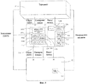
С целью устранения указанных недостатков патент США No. 4758718 под названием "Чип-карта повышенной секретности с обновляемым паролем", Фуджисаки и другие, раскрывает чип-карту, снабженную микропроцессором и памятью. На фиг.1 показано: 10 - чип-карта, используемая как средство идентификации для идентификации личности; 11 - микропроцессор, управляющий регистрацией и обновлением данных о пароле; 12 - интерфейс связи для соединения с терминальным устройством; 13 - клавиатура для ввода данных пароля; 14 - дисплей, например ЖК дисплей, для вывода данных пароля на экран; 15 - память с выделенными участками, на которых записаны данные, используемые для регистрации и обновления пароля; 16 - участок хранения пароля в памяти 15, причем участок пароля имеет размер 16 бит; 17 - участок памяти, выделенный для хранения числа несовпадений при сравнении введенного пароля с паролем, хранящимся в памяти 15; 18 - участок памяти, выделенный для хранения данных о типе и свойствах чип-карты 10; 19 - батарея. В памяти 15 имеется участок, выделенный для регистрации пароля, где пароль регистрируется, и участок, выделенный для обновления пароля, где хранятся данные, необходимые для обновления пароля, записанного в участок памяти, выделенный для его регистрации. Пароль вводится с клавиатуры, а микропроцессор управляет операцией его регистрации в указанный участок памяти, выделенный для регистрации. При поступлении команды изменить пароль производится сравнение зарегистрированного числа ошибочных вводов пароля с числом, предварительно записанным в участок памяти, выделенный для обновления пароля. Если число ошибочных вводов пароля меньше этого предварительно записанного числа, происходит сброс участка памяти, выделенного для регистрации пароля, а также участка памяти, выделенного для обновления пароля, и затем выдается разрешение на регистрацию вновь введенного пароля в участке памяти, выделенном для его регистрации.US Pat. No. 4,758,718, entitled “High Security Chip Card with Updated Password,” Fujisaki and others, discloses a chip card equipped with a microprocessor and memory. Figure 1 shows: 10 - a chip card used as an identification tool for identifying a person; 11 - a microprocessor that controls the registration and updating of password data; 12 is a communication interface for connecting to a terminal device; 13 - keyboard for entering password data; 14 is a display, for example an LCD display, for displaying password data on a screen; 15 - memory with dedicated areas on which data used to register and update the password is recorded; 16 - section of the password storage in the
В настоящее время чип-карты, или "смарт-карты", широко используются в качестве средства платежа за купленные товары в месте покупки (известные как «банковские карты»), за звонки из телефонных автоматов, за парковку автомашины, за услуги мобильной связи (например SIM карты), а также за медицинское обслуживание, проезд в общественном транспорте, пользование электронным кошельком и т.д. Каждый из этих видов оплаты обслуживается определенной карточкой: кредитной, телефонной, парковочной, или SIM-картой, предназначенной для глобальной системы мобильной связи (GSM), и т.д.Currently, chip cards, or “smart cards,” are widely used as a means of payment for purchased goods at the place of purchase (known as “bank cards”), for calls from telephone machines, for parking a car, for mobile communication services ( for example SIM cards), as well as for medical care, travel in public transport, using an electronic wallet, etc. Each of these types of payment is serviced by a specific card: credit, telephone, parking, or SIM-card designed for the global system of mobile communications (GSM), etc.
Недостаток такого карточного разнообразия состоит в том, что одна из этих карточек может оказаться недоступной в нужный момент - либо ее оставили дома, либо она нуждается в пополнении, либо истек срок ее годности. Кроме того, крайне неудобно контролировать дееспособность всех этих карточек и постоянно иметь их при себе. Поэтому имеется необходимость в создании так называемых многофункциональных карт.The disadvantage of this card variety is that one of these cards may not be available at the right time - either it was left at home, or it needs to be replenished, or its expiration date has expired. In addition, it is extremely inconvenient to monitor the legal capacity of all these cards and constantly have them with you. Therefore, there is a need to create the so-called multi-functional cards.
Так, в патенте США No. 6325293, под названием "Способ и система для многоцелевого использования чип-карты", Морено, описана чип-карта, содержащая устройство активации применения по умолчанию, устройство активации конкретного целевого применения и коммутирующее устройство для активации определенной конфигурации чип-карты по команде - либо в виде карты для применения по умолчанию, либо в виде карты для конкретного целевого применения. На фиг.2 показаны организация и общая последовательность операций в соответствии с этим способом.So, in U.S. Pat. 6325293, entitled “Method and System for Multipurpose Use of a Chip Card,” Moreno, describes a chip card containing a default application activation device, a specific application activation device, and a switching device for activating a specific configuration of the chip card by command — either in as a map for a default application, or as a map for a specific target application. Figure 2 shows the organization and overall sequence of operations in accordance with this method.
Как показано на фиг.2, клиент 20 приобрел абонемент у оператора 21, обслуживающего радиотелефон 22 клиента, включающий не только на общую услугу радиотелефонной связи, но и на специальную услугу, например плату за парковку, которая включается отдельным пунктом в список расходов на телефонную связь, который ежемесячно выставляется оператором 21 (в позиции 23 показано выставление счета).As shown in FIG. 2,
После того, как водитель припарковал свою автомашину рядом с электронным счетчиком 24 типа "заплати и покажи", запрограммированным на считывание предварительно оплаченных парковочных карточек, выдаваемых городом 25, водитель может обнаружить, что у него нет при себе парковочной карточки или карточка исчерпала свой лимит, или стала непригодной. В этом случае, чтобы оплатить время стоянки по электронному счетчику, водитель активизирует "парковочную" команду на своем радиотелефоне, например, нажав кнопку 26 или выбрав опцию в меню дополнительных услуг, предоставляемых его мобильным оператором. По этой команде SIM-карта 27 радиотелефона "перестраивается" в парковочную карточку. Водитель извлекает SIM-карту 27 из своего радиотелефона и вводит ее (стрелка 28) в слот электронного счетчика 24, который воспринимает и дебетует эту карту как парковочную. После этого водитель снова вводит карту 27 в радиотелефон 22 (стрелка 29), где она считывается и автоматически перестраивается для выполнения функций глобальной мобильной связи (GSM).After the driver has parked his car next to the pay-and-show
Хотя такие многофункциональные карты технически осуществимы, однако, как показали многочисленные эксперименты, их применение трудно реализовать на практике.Although such multifunctional cards are technically feasible, however, as shown by numerous experiments, their application is difficult to put into practice.
Широкое применение смарт-карт в мире мобильной связи, таких как SIM-карты для системы GSM, USIM-карты для системы WCDMA, RUIM-карты для системы CDMA2000 и PIM-карты для сети PHS, стимулировало разработку разнообразных методов обеспечения безопасности при использовании таких карт с мобильными телефонами (карты типа SIM/USIM/RUIM/PIM в дальнейшем будут называться UICC, универсальными картами на интегральных схемах). Операторы мобильных телефонов обеспечивают безопасность мобильных услуг, устанавливая соответствие между кодами, введенными на смарт-карты, и кодами, которые выдаются клиентам. Кроме того, за дополнительную плату эти операторы предоставляют и другие услуги, например, мобильные банковские услуги или торговля акциями, записывая на SIM-карты коды банков и других провайдеров. Манипуляции с этими кодами производятся с помощью интерфейса набора инструментов SIM (STK), который обеспечивает сама SIM-карта. С появлением радиотелефонов, поддерживающих протокол WAP (протокол беспроводного доступа), производители SIM-карт, стремясь обеспечить безопасность связи по протоколу WAP, разработали модуль WIM (модуль беспроводной идентификации), при этом сертификат и алгоритм PKI записывались на SIM-карту (SWIM-карту) или другую отдельную WIM-карту, которую можно было вводить в другой слот мобильного телефона.The widespread use of smart cards in the world of mobile communications, such as SIM cards for the GSM system, USIM cards for the WCDMA system, RUIM cards for the CDMA2000 system and PIM cards for the PHS network, has stimulated the development of various security methods when using such cards with mobile phones (cards like SIM / USIM / RUIM / PIM will be called UICC, universal cards on integrated circuits). Mobile phone operators ensure the security of mobile services by establishing a correspondence between the codes entered on smart cards and the codes that are issued to customers. In addition, for an additional fee, these operators provide other services, for example, mobile banking services and stock trading, writing codes of banks and other providers on SIM cards. Manipulations with these codes are performed using the SIM Toolkit (STK) interface, which is provided by the SIM card itself. With the advent of cordless telephones that support the WAP protocol (wireless access protocol), SIM card manufacturers, striving to ensure the security of WAP communication, developed the WIM module (wireless identification module), while the certificate and PKI algorithm were recorded on the SIM card (SWIM card ) or another separate WIM card that could be inserted into another slot of a mobile phone.
Клавиатура и дисплей мобильного телефона способствуют более широкому пользовательскому интерфейсу для вставленной смарт-карты, а также мобильная природа удаленного доступа к провайдерам услуг обеспечивает мобильность этих услуг. Для того чтобы сделать возможными мобильные услуги, провайдеры услуг, например банки, поставщики кредитных и проездных карточек, провайдеры услуг сертификатов и биржевые маклеры, охотно склоняются к сотрудничеству с мобильными операторами в разработке более совершенных SIM-карт, таким образом обеспечивая услуги, поддерживаемые их сферой деятельности. Однако, ввиду того что предоставление управление возможностями и функциями SIM-карт находятся под контролем мобильных операторов, формируется замкнутая система с участием только допущенных сторон. Более того, отношения между провайдерами услуг и мобильными операторами характеризуются взаимным недоверием, т.к. и те и другие стремятся получить контроль над методами оплаты и обеспечением безопасности. Этот фактор является основным препятствием, тормозящим решение вопросов безопасности услуг мобильной связи.The keyboard and display of the mobile phone contribute to the wider user interface for the inserted smart card, and the mobile nature of remote access to service providers ensures the mobility of these services. In order to enable mobile services, service providers such as banks, credit and travel card providers, certificate service providers and stockbrokers are willing to work with mobile operators to develop more advanced SIM cards, thus providing services supported by their field activities. However, due to the fact that the provision of control over the capabilities and functions of SIM cards is under the control of mobile operators, a closed system is formed with the participation of only authorized parties. Moreover, the relationship between service providers and mobile operators is characterized by mutual distrust, as both strive to gain control over payment methods and security. This factor is the main obstacle hindering the solution of security issues of mobile communication services.
Существует и еще одна актуальная проблема смарт-карты в мире мобильных услуг, которая связана с так называемой "множественной собственностью" на SIM-карты. Эта проблема проявляется в стремлении отдельного пользователя мобильного телефона использовать не одну, а несколько SIM-карт, причем от разных мобильных операторов, что объясняется его желанием:There is another urgent problem of smart cards in the world of mobile services, which is associated with the so-called "multiple ownership" of SIM cards. This problem manifests itself in the desire of an individual user of a mobile phone to use not one but several SIM cards, moreover, from different mobile operators, which is explained by his desire:
- иметь раздельные счета для личного и делового использования;- have separate accounts for personal and business use;
- пользоваться отдельными SIM-картами от мобильных операторов из разных стран, чтобы во время поездок за границу не платить комиссионные за роуминг:- use separate SIM-cards from mobile operators from different countries, so that when traveling abroad do not pay fees for roaming:
- иметь отдельные SIM-карты для различных сервисных планов, например, для звонков в дневное время и для звонков не в час пик;- have separate SIM cards for various service plans, for example, for calls during the daytime and for calls not at rush hour;
- иметь отдельные SIM-карты для пакетов с льготными тарифами для экономии денег.- have separate SIM cards for packages with preferential rates to save money.
Для решения этой проблемы были разработаны специальные мобильные телефоны с возможностью использования двойной микросхемы или двойного слота, при помощи выполнения дополнительного слота для микросхемы в мобильном телефоне, чтобы мобильный оператор или другой поставщик услуг мог предложить пользователю отдельную смарт-карту или SIM-карту, хранящую свои коды. Однако такие специальные телефоны обычно дорого стоят и не пользуются популярностью у пользователя, что приводит к фрагментации рынка поставщиков услуг.To solve this problem, special mobile phones have been developed with the possibility of using a double microcircuit or a dual slot by using an additional microcircuit slot in a mobile phone so that the mobile operator or other service provider can offer the user a separate smart card or SIM card that stores their codes. However, such special phones are usually expensive and not popular with the user, which leads to fragmentation of the market for service providers.
Поэтому необходимо создать такую смарт-карту, которая устраняла бы недостатки известных аналогичных устройств и решала бы указанные выше проблемы.Therefore, it is necessary to create such a smart card that would eliminate the shortcomings of known similar devices and solve the above problems.
ОПИСАНИЕ ИЗОБРЕТЕНИЯDESCRIPTION OF THE INVENTION
В данном разделе собраны и описаны некоторые признаки заявляемого изобретения. Другие его признаки будут раскрыты в последующих разделах. Настоящее изобретение допускает различные модификации, не выходящие за пределы сущности и объема, прилагаемой формулы изобретения.In this section, some features of the claimed invention are collected and described. Other features will be disclosed in subsequent sections. The present invention allows various modifications, without going beyond the essence and scope of the attached claims.
В соответствии с одним аспектом данного изобретения, смарт-карта содержит процессор; первый интерфейс для связи с терминалом; второй интерфейс для связи с другой смарт-картой; и генератор сигнала сброса (RST) для передачи этого сигнала на другую смарт-карту.In accordance with one aspect of the present invention, the smart card comprises a processor; a first interface for communicating with a terminal; a second interface for communicating with another smart card; and a reset signal generator (RST) for transmitting this signal to another smart card.
Предпочтительно, процессор дополнительно содержит буфер для приема и хранения сигнала ответа на сброс (ATR) от другой смарт-карты.Preferably, the processor further comprises a buffer for receiving and storing a reset response signal (ATR) from another smart card.
Предпочтительно, процессор дополнительно содержит генератор сигнала ответа на сброс (ATR) для генерирования сигнала ответа на сброс.Preferably, the processor further comprises a reset response signal (ATR) generator for generating a reset response signal.
Предпочтительно, процессор дополнительно содержит генератор запроса PTS (выбор типа протокола), для генерирования сигнала запроса PTS на другую смарт-карту.Preferably, the processor further comprises a PTS request generator (protocol type selection), for generating a PTS request signal to another smart card.
Предпочтительно, процессор дополнительно содержит генератор сигнала ответа на запрос PTS для генерирования сигнала ответа на запрос PTS на терминал.Preferably, the processor further comprises a PTS request response signal generator for generating a PTS request response signal to the terminal.
Предпочтительно, процессор дополнительно содержит устройство распознавания сигнала PTS, определяющее, приемлем ли сигнал запроса PTS как для терминала, так и для другой смарт-карты.Preferably, the processor further comprises a PTS signal recognition device that determines whether the PTS request signal is acceptable for both the terminal and another smart card.
Предпочтительно, процессор дополнительно содержит синхронизирующий регулятор для подачи импульсов тактовой частоты на другую смарт-карту.Preferably, the processor further comprises a clock controller for supplying clock pulses to another smart card.
Более предпочтительно, процессор содержит устройство для распознавания команды APDU (модуль данных протокола приложения), определяющее, связан ли передаваемый терминалом сигнал команды АРDU с указанной смарт-картой или с указанной другой смарт-картой.More preferably, the processor comprises an APDU command recognition device (application protocol data module) that determines whether the APDU command signal transmitted by the terminal is associated with the indicated smart card or with the specified other smart card.
Более предпочтительно, процессор дополнительно содержит генератор команды APDU для генерирования сигнала команды APDU на указанную другую смарт-карту.More preferably, the processor further comprises an APDU command generator for generating an APDU command signal to said other smart card.
Более предпочтительно, процессор дополнительно содержит буфер для приема и хранения сигнала ответа на команду APDU, поступившего от другой смарт-карты.More preferably, the processor further comprises a buffer for receiving and storing an APDU response signal from another smart card.
Более предпочтительно, процессор дополнительно содержит генератор ответа на команду APDU для генерирования сигнала ответа на команду APDU на терминал.More preferably, the processor further comprises an APDU command response generator for generating an APDU command response signal to the terminal.
Более предпочтительно, смарт-карта снабжена антенной для связи с бесконтактным терминалом.More preferably, the smart card is provided with an antenna for communication with a contactless terminal.
Более предпочтительно, смарт-карта выполнена в виде SIM-карты (модуль идентификации абонента), USIM-карты (универсальный модуль идентификации абонента), UIM-карты (модуль идентификации пользователя) и RUIM-карты (сменный модуль идентификации пользователя).More preferably, the smart card is in the form of a SIM card (subscriber identity module), a USIM card (universal subscriber identity module), a UIM card (user identification module), and a RUIM card (removable user identification module).
Более предпочтительно, смарт-карта выполнена в виде кредитной карточки, платежной карточки и карточки для банкомата.More preferably, the smart card is in the form of a credit card, a payment card, and an ATM card.
КРАТКОЕ ОПИСАНИЕ ЧЕРТЕЖЕЙBRIEF DESCRIPTION OF THE DRAWINGS
Указанные выше цели и преимущества настоящего изобретения станут более очевидными для специалистов в данной области техники из следующего ниже подробного описания изобретения и прилагаемых чертежей, на которых:The above objectives and advantages of the present invention will become more apparent to those skilled in the art from the following detailed description of the invention and the accompanying drawings, in which:
на фиг.1 изображена блок-схема стандартной чип-карты;figure 1 shows a block diagram of a standard chip card;
на фиг.2 изображена схема использования чип-карты в соответствии с другим известным способом;figure 2 shows a diagram of the use of a chip card in accordance with another known method;
на фиг.3 изображена блок-схема первого варианта осуществления смарт-карты в двухкарточной системе для использования с терминалом транзакций в соответствии с настоящим изобретением;figure 3 shows a block diagram of a first embodiment of a smart card in a dual card system for use with a transaction terminal in accordance with the present invention;
на фиг.4 изображена блок-схема второго варианта осуществления смарт-карты в двухкарточной системе для использования с терминалом связи в соответствии с настоящим изобретением;4 is a block diagram of a second embodiment of a smart card in a dual card system for use with a communication terminal in accordance with the present invention;
на фиг.5А и 5В изображена блок схема, иллюстрирующая способ транзакции при использовании двухкарточной системы в соответствии с настоящим изобретением.5A and 5B are a flowchart illustrating a transaction method when using a dual-card system in accordance with the present invention.
ПОДРОБНОЕ ОПИСАЕНИЕ ПРЕДПОЧТИТЕЛЬНЫХ ВАРИАНТОВ РЕАЛИЗАЦИИ ИЗОБРЕТЕНИЯDETAILED DESCRIPTION OF THE PREFERRED EMBODIMENTS
В соответствии с настоящим изобретением предлагается смарт-карта в двухкарточной системе и способ ее использования. Цели и преимущества данного изобретения станут более очевидными для специалистов в данной области техники из следующего ниже подробного описания вариантов осуществления настоящего изобретения, которое не ограничивается только этими вариантами осуществления.In accordance with the present invention, there is provided a smart card in a two-card system and a method for using it. The objectives and advantages of this invention will become more apparent to those skilled in the art from the following detailed description of embodiments of the present invention, which is not limited to these embodiments only.
Первый вариант осуществления изобретенияFirst Embodiment
На фиг.3. показана блок-схема первого варианта осуществления заявляемой смарт-карты в двухкарточной системе для использования совместно с терминалом транзакций в соответствии с настоящим изобретением. Как видно из фиг.3, указанная двухкарточная система, предназначенная для использования с терминалом транзакций 30, состоит из первой карты 32 и второй карты 31. Первая карта 32 имеет первую память 321 для хранения первой идентификационной информации, используемой во время целевой транзакции с терминалом транзакций 30. Вторая карта 31 содержит процессор 310, генератор 314b сигнала сброса (RST), вторую память 311, третью память 312, четвертую память 313 и синхронизирующий регулятор 34а. Вторая память 311 хранит вторую идентификационную информацию, используемую во время целевой транзакции с терминалом транзакций 30. Третья память 312 хранит информацию о транзакции. Четвертая память 313 хранит первые персональные данные, которые не защищены первой картой 32. Синхронизирующий регулятор 34а принимает синхронизирующий сигнал от терминала транзакций 30 по шине синхронизирующих импульсов 34 (CLK) и выдает другой синхронизирующий сигнал на первую карту 32 по шине синхронизирующих импульсов 37. Синхронизирующий сигнал на выходе регулятора 34а может быть таким же или отличаться от сигнала, посылаемого терминалом транзакций 30.In figure 3. shows a block diagram of a first embodiment of the inventive smart card in a dual-card system for use with a transaction terminal in accordance with the present invention. As can be seen from figure 3, the indicated two-card system, intended for use with the
Первая карта 32 устанавливается с первой операционной системой, а вторая карта 31 со второй операционной системой. Вторая карта 31 может управлять первой картой 32, выполняя одновременно функции смарт-карты и считывающего устройства.The
Вторая карта 31 связана с терминалом транзакций 30 тремя шинами: шиной сброса 33 (RST), шиной синхронизирующих импульсов 34 (CLK) и портом ввода/вывода 35 (I/O). Кроме того, имеются шина подачи напряжения питания VCC и заземляющая шина GND. В качестве терминала транзакций 30 здесь используется либо устройство для считывания смарт-карты в портативном приборе, либо стационарный терминал, например банкомат (ATM) или кассовый аппарат (POS). Как показано, первая карта 32 связана со второй картой 31 тремя шинами, а именно: шиной сброса 36, шиной синхронизирующих импульсов 37 и портом ввода/вывода 38. Фактически вторая карта 31 снабжена двумя портами ввода/вывода, 35 и 38, для сообщения с терминалом транзакций 30 и первой картой 32, соответственно. Вторая карта 31 может легко обрабатывать различные протоколы связи, предлагаемые портами ввода/вывода 35 и 38. В соответствии с первым вариантом осуществления настоящего изобретения вторая карта 31 способна также выдавать сигнал команды APDU (модуль данных протокола приложения) через порт ввода/вывода 38 на первую карту 32. Вторая карта 31 передает также синхронизирующие сигналы на первую карту 32 по шине синхронизирующих импульсов 27. Таким образом, вторая карта 31 функционирует и как смарт-карта, и как устройство для чтения смарт-карт в управлении первой карты 32.The
В общем случае смарт-карта передает сигнал ATR (ответа на сброс) через порт ввода/вывода на устройство считывания после подачи напряжения питания VCC и появления сигналов CLK и RST, т.е. синхронизирующего сигнала и сигнала сброса. Строка данных и элементы данных сигнала ответа на сброс (ATR) определены и подробно описаны в стандарте ISO/IEC 7816-3. Основной формат сигнала ATR показан в Таблице.In general, a smart card transmits an ATR (response to reset) signal through an input / output port to a reader after applying a VCC power supply and the appearance of CLK and RST signals, i.e. timing signal and reset signal. The data string and data elements of the reset response signal (ATR) are defined and described in detail in ISO / IEC 7816-3. The main ATR signal format is shown in the Table.
Два первых байта TS и Т0 определяют различные основные параметры передачи данных и наличие последующих байтов. Символы интерфейса обозначают специальные параметры передачи данных для протокола и играют существенную роль для последующей передачи данных. Исторические символы характеризуют степень распространения базовых функций смарт-карты. Контрольный символ, представляющий собой контрольную сумму предыдущих байтов, может быть опционально передан как последний байт сигнала ответа на сброс (ATR) в зависимости от протокола передачи. Кроме того, строка данных сигнала ATR всегда передается с величиной делителя и содержит различную информацию о протоколе передачи и о смарт-карте. Как известно, смарт-карта показывает различные параметры передачи данных в символах интерфейса сигнала ATR, например, протокол передачи и время ожидания символа.The first two bytes TS and T0 determine the various basic parameters for transmitting data and the availability of subsequent bytes. Interface symbols denote special parameters of data transfer for the protocol and play an essential role for subsequent data transfer. Historical symbols characterize the extent to which the basic functions of a smart card are spread. The check character, which is the checksum of the previous bytes, can optionally be transmitted as the last byte of the reset response signal (ATR) depending on the transmission protocol. In addition, the data line of the ATR signal is always transmitted with a divisor value and contains various information about the transmission protocol and the smart card. As you know, a smart card shows various parameters of data transfer in the characters of the ATR signal interface, for example, the transmission protocol and the symbol timeout.
Кроме того, если терминал собирается изменить один или более из этих параметров, необходимо выполнить процедуру PTS (выбор типа протокола) перед фактическим выполнением самого протокола. У терминала имеется возможность изменить определенные параметры протокола, пока это разрешено смарт-картой.In addition, if the terminal is about to change one or more of these parameters, it is necessary to perform the PTS (protocol type selection) procedure before actually executing the protocol itself. The terminal has the ability to change certain protocol parameters while it is allowed by the smart card.
В соответствии с настоящим изобретением (см. фиг.3 и 5) процессор 310 второй карты 31 содержит в своем составе буфер 318, генератор 319 сигнала ATR, устройство 315а распознавания сигнала PTS, генератор 315b запроса PTS, генератор 315с ответа на запрос PTS, устройство 316а распознавания сигнала команды APDU, генератор 316b сигнала команды APDU и генератор 317 сигнала ответа_на команду APDU. Во время транзакции терминал транзакций 30 определяет, существует ли в системе транзакций первая карта 32 после подачи на нее напряжения питания (шаги S500 и S501). Если первая карта 32 в системе транзакций не существует, терминал транзакций 30 будет выполнять транзакцию по умолчанию со второй картой 31 (шаг S502). Кроме того, транзакция по умолчанию может выполняться и по бесконтактной связи с другим терминалом посредством антенны, которой снабжена вторая карта 31. В этом случае связь осуществляется по радиосигналам. С другой стороны, если терминал транзакций 30 обнаружит, что первая карта 32 существует в системе транзакций, он начнет функционировать в двухкарточной системе, в которой все сигналы, передаваемые на первую карту 32, проходят через вторую карту 31. Иными словами, терминал транзакций 30 не общается непосредственно с первой картой 32, т.е. вторая карта 31 является ведомой по отношению к терминалу транзакций 30 и в то же время ведущей по отношению к первой карте 32. Поэтому сигнал сброса (RST2) от терминала транзакций 30 посылаются непосредственно только на вторую карту 31 независимо от того, относится ли данная транзакция к первой карте 32 или ко второй карте 31. Как только вторая карта получит сигнал сброса RST2, генератор 314b сигнала сброса начнет генерировать сигнал сброса (RST1), передавая его на первую карту 32 (шаг S503). После получения сигнала сброса RST1 первая карта 32 генерирует сигнал ответа на сброс (ATR1), посылая его в буфер 318 (например, буфер, работающий по принципу "первым пришел - первым вышел"), находящийся на второй карте 31 (шаг S504). После получения сигнала ATR1 от первой карты 32 генератор 319 сигнала ответа на сброс ATR, находящийся на второй карте 31, начинает генерировать еще один сигнал ответа на сброс (ATR2) посылая его на терминал транзакций 30 (шаг S505).In accordance with the present invention (see FIGS. 3 and 5), the
В общем случае сигнал ответа на сброс (ATR) должен появляться между 400 и 40000 синхронизирующими импульсами после того, как терминал транзакций 30 выдаст сигнал сброса. При тактовой частоте 3.5712 МГц это соответствует интервалу от 112µs до 11.20 ms, а при тактовой частоте 4.9152 МГц этот интервал будет в пределах от 81.38 µs до 8.14 ms. Если терминал транзакций 30 не получит сигнал ответа (ATR) на сброс в пределах этого интервала, он повторит последовательность активации несколько раз (обычно до трех раз), чтобы попытаться обнаружить сигнал ответа на сброс (ATR). Если эти попытки закончатся неудачей, терминал решит, что карта неисправна и отреагирует соответствующим образом. Однако, если, как указано выше, сигнал ATR1 послан на вторую карту 31 после того, как эта карта получила сигнал сброса RST2 от терминала транзакций 30, то сигнал ATR1 не успеет появиться в отведенный промежуток времени. Поэтому для решения данной проблемы генератор 314b сигнала сброса (RST), находящийся на второй карте 31, программируется на спонтанное генерирование сигнала сброса RST1, который передается на первую карту 32 после подачи напряжения питания на вторую карту 31 независимо от того, получен ли сигнал RST2 от терминала транзакций 30. Иными словами, генератор 314b сигнала сброса (RST) необязательно должен ждать того момента, когда терминал транзакций 30 выдаст сигнал RST2 перед посылкой сигнала RST1 на первую карту 32, чтобы не допустить задержку в реагировании на действия терминала транзакций 30. Поэтому вторая карта 31 хранит переданный первой картой 32 сигнал ответа на сброс ATR1 в буфере 318, пока не будет получен сигнал сброса RST2. Таким образом, сигнал ответа на сброс ATR1 может быть передан сразу же после появления сигнала сброса RST2.In general, a reset response signal (ATR) should appear between 400 and 40,000 clock pulses after
После того, как терминал транзакций 30 получит сигнал ответа на сброс (ATR) от генератора 319, он начнет непрерывно посылать сигнал PTS1, т.е. сигнал выбора типа протокола, на вторую карту 31 для согласования выбора типа протокола (шаг S506). Затем находящийся на второй карте 31 генератор 315b сигнала запроса PTS (выбор типа протокола) начнет генерировать сигнал PTS2, посылая его на первую карту 32. В ответ на сигнал PTS2 первая карта 32 передаст сигнал PTS3 обратно на вторую карту 31. В соответствии с этим, находящееся на второй карте 31 устройство 315а распознавания сигнала PTS определит, смогут ли первая 32 и вторая 31 карты по сигналу PTS3 от первой карты 31 обработать протокол, указанный первым сигналом запроса PTS, посланным терминалом транзакций 30. Затем находящийся на второй карте 31 генератор 315 с сигнала ответа на запрос PTS передаст сигнал PTS4, т.е. еще один сигнал запроса PTS, на терминал транзакций 30. Эта последовательность действий будет выполняться до тех пор, пока протокол, указанный терминалом транзакций 30, не будет согласован между терминалом транзакций 30 и второй картой 31, а также между второй картой 31 и первой картой 32.After the
После согласования протокола терминал транзакций 30 выдаст запрос на транзакцию, послав сигнал команды c-APDU1 (модуль данных протокола приложения) на устройство 316а распознавания команды APDU, находящееся на второй карте 31 (шаг S507). После получения сигнала c-APDU1 устройство 316а распознавания команды APDU определяет, какую транзакцию запрашивает сигнал c-APDU1 - транзакцию по умолчанию или целевую транзакцию (шаг S508). Если сигнал c-APDU1 от терминала транзакций 30 запрашивает целевую транзакцию, то находящийся на второй карте 31 генератор 316b сигналов команды APDU отправит сигнал c-APDU2 на первую карту 32 (шаг S509). Затем будет выполнена целевая транзакция (шаг S510), и первая карта 32 отправит сигнал r-APDU1, т.е. ответ на команду APDU, в буфер 318, находящийся на второй карте 31 (шаг S511). Получив сигнал r-APDU1 от первой карты 32, генератор 317 сигнала ответа на команду APDU на второй карте 32 пошлет сигнал r-APDU2, т.е. еще один сигнал ответа на команду APDU, на терминал транзакций 30, указывая этим, что целевая транзакция выполнена (шаг S512).After negotiating the protocol, the
В данном варианте осуществления настоящего изобретения информация, относящаяся к транзакции, переписывается процессором 310, когда на основании анализа первой или второй идентификационной информации терминал транзакций 30 утвердит запрос на транзакцию, переданный первой картой. Информацией о транзакции может быть, например, баланс на платежной карточке. В этом случае процессор 310 может либо увеличить, либо уменьшить этот баланс во время транзакции.In this embodiment of the present invention, transaction related information is overwritten by the
Кроме того, при введении в терминал транзакций двухкарточной системы вторая карта 31 может обнаружить наличие первой карты 32 в системе транзакций путем вычисления времени, которое требуется первой карте для формирования сигнала ответа на сброс ATR1; в качестве альтернативы вторая карта 31 может поддерживать интерфейс пользователя, например, меню приложения набора инструментов SIM на SIM-карте, чтобы пользователь мобильного телефона с двухкарточной системой мог конфигурировать наличие первой карты.In addition, when a two-card system is introduced into the transaction terminal, the
Например, платежная карточка (POS), которая хранит значения денежных сумм, может в соответствии с настоящим изобретением рассматриваться в качестве второй карты 31, а карточка для банкомата (ATM), хранящая банковский счет, может рассматриваться в качестве первой карты 32. Каждая из этих карточек выполняет определенную функцию. В данном изобретении платежная карточка может быть принята за основную, и кроме того она может выполнять функцию считывающего устройства терминала транзакций по отношению к карточке для банкомата. Таким образом, в соответствии с настоящим изобретением пользователь может перевести деньги с банковского счета карточки для банкомата на электронный кошелек своей платежной карточки через терминал транзакций. Если мобильный телефон снабжен указанной двухкарточной системой, то в терминах настоящего изобретения SIM-карта является второй картой, а платежная карточка является первой картой. Пользователь может перевести деньги на электронный кошелек платежной карточки по SMS, посланной на его мобильный телефон из банка в ответ на SMS, которое он послал в банк со своего мобильного телефона с запросом пополнить счет на платежной карточке. В этом случае мобильный телефон выполняет функцию терминала. Таким образом, настоящее изобретение предлагает двухкарточную систему для использования с двумя различными терминалами транзакций, чтобы на практике облегчить операции с передачей информации.For example, a payment card (POS) that stores cash amounts can, in accordance with the present invention, be regarded as a
Второй вариант осуществления изобретенияSecond Embodiment
На фиг.4 представлена блок-схема второго варианта осуществления заявляемой смарт-карты в двухкарточной системе для использования с терминалом связи в соответствии с настоящим изобретением. Как показано на фиг.4, эта двухкарточная система, используемая с терминалом связи 40, состоит из первой карты 42 и второй карты 41. Первая карта 42 имеет первую память 421 для хранения первой идентификационной информации, включая первые персональные данные, первые секретные коды и первую защитную функцию для использования во время связи с отдаленным терминалом 49 через терминал связи 40. Вторая карта 41 содержит процессор 410, вторую память 411, третью память 412 и избирательное устройство 413. Вторая память 411 хранит вторую идентификационную информацию, включая вторые персональные данные, вторые секретные коды и вторую защитную функцию для использования во время связи с отдаленным терминалом 49 через терминал связи 40. Третья память 412 может хранить первые персональные данные, не защищенные первой картой 32. Избирательное устройство 413 служит для определения того, какая из двух защитных функций (первой или второй карты) должна выполняться. Процессор 410 может задействовать или не задействовать первую карту 42 в зависимости от того, какая из двух карт выбрана избирательным устройством 413.Figure 4 presents a block diagram of a second embodiment of the inventive smart card in a dual card system for use with a communication terminal in accordance with the present invention. As shown in FIG. 4, this two-card system used with the
В данном варианте реализации заявляемого изобретения любая из указанных карт (41 или 42) может быть картой различных мобильных систем связи, а именно: SIM-картой (модуль идентификации абонента), USIM-картой (универсальный модуль идентификации абонента), UIM-картой (модуль идентификации пользователя) и RUIM-картой (сменный модуль идентификации пользователя). Если одна из двух SIM-карт условно считается первой картой 42, а другая - второй картой 41, то вторая SIM-карта могла бы интегрировать два набора информации, хранящиеся на обеих SIM-картах, например два телефонных справочника. Избирательное устройство обычно представляет собою меню набора инструментов SIM и поддерживает интерфейс пользователя при выборе SIM-карты, используемой для регистрации в мобильной сети. На практике двухкарточная система способна интегрировать две SIM-карты в одном терминале связи, т.е. в мобильном телефоне. В соответствии с настоящим изобретением предполагается, что компания мобильной связи может предложить своему клиенту услугу по интеграции старой SIM-карты от другой компании и новой SIM-карты. Пользователь, выбирая по своему желанию одну из двух SIM-карт, мог бы делать телефонные звонки с двух разных телефонных номеров.In this embodiment of the claimed invention, any of these cards (41 or 42) can be a card of various mobile communication systems, namely: a SIM card (subscriber identity module), a USIM card (universal subscriber identity module), a UIM card (module user identification) and RUIM-card (removable user identification module). If one of the two SIM cards is conventionally considered the
Показанные выше конкретные примеры осуществления настоящего изобретения допускают различные модификации, однако понятно, что данное изобретение не ограничивается только этими примерами и допускает внесение изменений и дополнений, которые не выходят за рамки его сути и объема, определяемые прилагаемой формулой изобретения.The above specific embodiments of the present invention allow various modifications, however, it is understood that the present invention is not limited to these examples only and allows changes and additions that do not go beyond its essence and scope, as defined by the attached claims.
Claims (13)
первый интерфейс для использования при общении с терминалом;
второй интерфейс для использования при общении с другой смарт-картой;
процессор для генерирования сигнала ответа на сброс (ATR) для указанного терминала; и
генератор сигнала сброса (RST) для генерирования сигнала сброса на указанную другую смарт-карту.1. A smart card containing:
The first interface to use when communicating with the terminal;
a second interface for use when communicating with another smart card;
a processor for generating a reset response signal (ATR) for said terminal; and
a reset signal generator (RST) for generating a reset signal to a specified other smart card.
Applications Claiming Priority (2)
| Application Number | Priority Date | Filing Date | Title |
|---|---|---|---|
| US11/296,309 US7395973B2 (en) | 2005-12-08 | 2005-12-08 | Smart card |
| US11/296,309 | 2005-12-08 |
Publications (2)
| Publication Number | Publication Date |
|---|---|
| RU2008125887A RU2008125887A (en) | 2010-01-20 |
| RU2406145C2 true RU2406145C2 (en) | 2010-12-10 |
Family
ID=38123338
Family Applications (1)
| Application Number | Title | Priority Date | Filing Date |
|---|---|---|---|
| RU2008125887/08A RU2406145C2 (en) | 2005-12-08 | 2006-03-28 | Smart card |
Country Status (16)
| Country | Link |
|---|---|
| US (1) | US7395973B2 (en) |
| EP (1) | EP1958127B1 (en) |
| JP (1) | JP5019635B2 (en) |
| KR (1) | KR100977916B1 (en) |
| AU (1) | AU2006323231B2 (en) |
| BR (1) | BRPI0620579A2 (en) |
| CA (1) | CA2632733C (en) |
| DK (1) | DK1958127T3 (en) |
| ES (1) | ES2391982T3 (en) |
| NO (1) | NO341003B1 (en) |
| NZ (1) | NZ568258A (en) |
| PL (1) | PL1958127T3 (en) |
| PT (1) | PT1958127E (en) |
| RU (1) | RU2406145C2 (en) |
| WO (1) | WO2007067202A2 (en) |
| ZA (1) | ZA200804265B (en) |
Families Citing this family (26)
| Publication number | Priority date | Publication date | Assignee | Title |
|---|---|---|---|---|
| US20070184858A1 (en) * | 2006-02-09 | 2007-08-09 | Agere Systems Inc. | Method of attaching mobile communication tasks to a Subscriber Information Module card and mobile communication device incorporating the same |
| WO2007094624A1 (en) * | 2006-02-17 | 2007-08-23 | Ktfreetel Co., Ltd. | Ic card, terminal with ic card and initializing method thereof |
| US9047601B2 (en) * | 2006-09-24 | 2015-06-02 | RFCyber Corpration | Method and apparatus for settling payments using mobile devices |
| KR20090032678A (en) * | 2007-09-28 | 2009-04-01 | 삼성전자주식회사 | Terminal having dual sim card and method for executing function thereof |
| US10783514B2 (en) * | 2007-10-10 | 2020-09-22 | Mastercard International Incorporated | Method and apparatus for use in personalizing identification token |
| US7942325B2 (en) * | 2008-01-29 | 2011-05-17 | Research In Motion Limited | Optimized smart card driver performance |
| US20090239575A1 (en) * | 2008-03-21 | 2009-09-24 | Mediatek Inc. | Methods for processing apparatus originated communication request, handling equipment identity requests and communication apparatuses utilizing the same |
| US8108002B2 (en) * | 2008-03-21 | 2012-01-31 | Mediatek Inc. | Communication apparatuses equipped with more than one subscriber identity card and capable of providing reliable communication quality |
| US8204542B2 (en) * | 2008-03-21 | 2012-06-19 | Mediatek Inc. | Methods for processing apparatus originated communication request and communication apparatuses utilizing the same |
| TW200945865A (en) | 2008-04-23 | 2009-11-01 | Mediatek Inc | Method for handling the equipment identity requests and communication apparatus utilizing the same |
| CN101981818B (en) * | 2008-08-08 | 2013-09-25 | Sk普兰尼特有限公司 | Interface system between a terminal and a smart card, method for same, and smart card applied to same |
| KR101095163B1 (en) * | 2008-08-27 | 2011-12-16 | 에스케이플래닛 주식회사 | System working together by terminal and smart card for processing widget and method thereof |
| US8201747B2 (en) * | 2008-11-26 | 2012-06-19 | Qsecure, Inc. | Auto-sequencing financial payment display card |
| KR20100074596A (en) * | 2008-12-24 | 2010-07-02 | 삼성전자주식회사 | Mutistandby terminal and method for offering tool kit menu thereof |
| GB2466663A (en) * | 2009-01-05 | 2010-07-07 | Nec Corp | Altering Maximum Power Supply to Smart Card |
| US8121601B2 (en) * | 2009-04-01 | 2012-02-21 | Mediatek Inc. | Methods for integrating cell measurement procedures of a communication apparatus and communication apparatuses utilizing the same |
| EP2273748A1 (en) * | 2009-07-09 | 2011-01-12 | Gemalto SA | Method of managing an application embedded in a secured electronic token |
| US20110192896A1 (en) * | 2010-02-09 | 2011-08-11 | Pauyi Technology Co., Ltd. | Electronic name card and electronic name card system using radio frequency or microwave identification |
| IT1404159B1 (en) * | 2010-12-30 | 2013-11-15 | Incard Sa | METHOD AND SYSTEM OF CONTROL OF A COMMUNICATION BETWEEN AN INTEGRATED CIRCUIT UNIVERSAL CARD AND AN EXTERNAL APPLICATION |
| TWM425346U (en) | 2011-05-20 | 2012-03-21 | Mxtran Inc | Integrated circuit film for smart card and mobile communication device |
| WO2013013184A2 (en) | 2011-07-20 | 2013-01-24 | Visa International Service Association | Expansion device placement apparatus |
| US20130201004A1 (en) * | 2012-01-20 | 2013-08-08 | Identive Group, Inc. | Proximity Devices and Systems that Support Multiple Formats |
| US9426127B2 (en) | 2012-05-02 | 2016-08-23 | Visa International Service Association | Small form-factor cryptographic expansion device |
| US9768815B2 (en) * | 2014-11-13 | 2017-09-19 | Blackberry Limited | System and method for providing service license aggregation across multiple physical and virtual SIM cards |
| US9729180B2 (en) * | 2014-11-13 | 2017-08-08 | Blackberry Limited | System and method for providing service license aggregation across multiple device SIM cards |
| US20210166183A1 (en) * | 2018-05-23 | 2021-06-03 | Yroo Inc. | Method and apparatus for decentralized information mining of online content |
Family Cites Families (16)
| Publication number | Priority date | Publication date | Assignee | Title |
|---|---|---|---|---|
| JP2930259B2 (en) * | 1991-04-22 | 1999-08-03 | 株式会社東芝 | Portable electronic devices |
| JPH07239922A (en) * | 1994-02-25 | 1995-09-12 | Dainippon Printing Co Ltd | Ic module for ic card |
| US6012634A (en) * | 1995-03-06 | 2000-01-11 | Motorola, Inc. | Dual card and method therefor |
| JPH1125233A (en) * | 1997-02-07 | 1999-01-29 | Oki America Inc | Method and device for ic card |
| US6577229B1 (en) * | 1999-06-10 | 2003-06-10 | Cubic Corporation | Multiple protocol smart card communication device |
| US6394343B1 (en) * | 1999-10-14 | 2002-05-28 | Jon N. Berg | System for card to card transfer of monetary values |
| WO2001029762A2 (en) * | 1999-10-20 | 2001-04-26 | Spyrus, Inc. | Method and system for an integrated circuit card interface device with multiple modes of operation |
| US7337332B2 (en) * | 2000-10-24 | 2008-02-26 | Nds Ltd. | Transferring electronic content |
| JP2002329180A (en) * | 2001-04-27 | 2002-11-15 | Toshiba Corp | Memory card having radio communication function and its data communication method |
| JP2003030613A (en) * | 2001-07-13 | 2003-01-31 | Hitachi Ltd | Storage device and data processor provided with the storage device |
| JP2003030596A (en) * | 2001-07-13 | 2003-01-31 | Hitachi Ltd | Storage device provided with logic channel management function |
| JP2004015667A (en) * | 2002-06-10 | 2004-01-15 | Takeshi Sakamura | Inter ic card encryption communication method, inter ic card encryption communication in electronic ticket distribution system, and ic card |
| US7367503B2 (en) * | 2002-11-13 | 2008-05-06 | Sandisk Corporation | Universal non-volatile memory card used with various different standard cards containing a memory controller |
| US20040162927A1 (en) * | 2003-02-18 | 2004-08-19 | Hewlett-Packard Development Company, L.P. | High speed multiple port data bus interface architecture |
| KR100579053B1 (en) * | 2004-08-26 | 2006-05-12 | 삼성전자주식회사 | Method of multi-interfacing between smart card and memory card and multi-interface card |
| CN2757375Y (en) * | 2004-11-25 | 2006-02-08 | 富士康(昆山)电脑接插件有限公司 | Electronic card connector |
-
2005
- 2005-12-08 US US11/296,309 patent/US7395973B2/en active Active
-
2006
- 2006-03-28 DK DK06739852.9T patent/DK1958127T3/en active
- 2006-03-28 PT PT06739852T patent/PT1958127E/en unknown
- 2006-03-28 JP JP2008544312A patent/JP5019635B2/en active Active
- 2006-03-28 AU AU2006323231A patent/AU2006323231B2/en not_active Ceased
- 2006-03-28 RU RU2008125887/08A patent/RU2406145C2/en active
- 2006-03-28 EP EP06739852A patent/EP1958127B1/en active Active
- 2006-03-28 PL PL06739852T patent/PL1958127T3/en unknown
- 2006-03-28 WO PCT/US2006/011329 patent/WO2007067202A2/en active Application Filing
- 2006-03-28 BR BRPI0620579-8A patent/BRPI0620579A2/en active IP Right Grant
- 2006-03-28 KR KR1020087016143A patent/KR100977916B1/en active IP Right Grant
- 2006-03-28 CA CA2632733A patent/CA2632733C/en active Active
- 2006-03-28 NZ NZ568258A patent/NZ568258A/en not_active IP Right Cessation
- 2006-03-28 ES ES06739852T patent/ES2391982T3/en active Active
-
2008
- 2008-05-14 NO NO20082228A patent/NO341003B1/en not_active IP Right Cessation
- 2008-05-16 ZA ZA200804265A patent/ZA200804265B/en unknown
Also Published As
| Publication number | Publication date |
|---|---|
| KR20080085856A (en) | 2008-09-24 |
| NO20082228L (en) | 2008-09-02 |
| EP1958127B1 (en) | 2012-08-15 |
| DK1958127T3 (en) | 2012-10-29 |
| NZ568258A (en) | 2011-07-29 |
| KR100977916B1 (en) | 2010-08-24 |
| RU2008125887A (en) | 2010-01-20 |
| CA2632733A1 (en) | 2007-06-14 |
| ES2391982T3 (en) | 2012-12-03 |
| EP1958127A4 (en) | 2009-12-16 |
| WO2007067202A3 (en) | 2009-05-28 |
| AU2006323231A1 (en) | 2007-06-14 |
| JP5019635B2 (en) | 2012-09-05 |
| ZA200804265B (en) | 2009-09-30 |
| CA2632733C (en) | 2011-11-01 |
| PT1958127E (en) | 2012-11-21 |
| US7395973B2 (en) | 2008-07-08 |
| PL1958127T3 (en) | 2013-01-31 |
| WO2007067202A2 (en) | 2007-06-14 |
| AU2006323231B2 (en) | 2009-10-29 |
| NO341003B1 (en) | 2017-08-07 |
| JP2009518740A (en) | 2009-05-07 |
| EP1958127A2 (en) | 2008-08-20 |
| BRPI0620579A2 (en) | 2012-05-02 |
| US20070131780A1 (en) | 2007-06-14 |
Similar Documents
| Publication | Publication Date | Title |
|---|---|---|
| RU2406145C2 (en) | Smart card | |
| AU2008298677B2 (en) | Wirelessly executing financial transactions | |
| TWI504229B (en) | Mobile device with electronic wallet function | |
| ES2662254T3 (en) | Method and mobile terminal device that includes smart card module and near field communications media | |
| US9349124B2 (en) | Integrated system and method for enabling mobile commerce transactions using active posters and contactless identity modules | |
| US10229397B2 (en) | Near field communication terminal capable of loading card with money and method of operating the same | |
| KR101247965B1 (en) | System and Method for payment using vehicle type NFC | |
| KR101025621B1 (en) | Method for Charging the Prepaid Card Function in Mobile Devices | |
| CN100483455C (en) | Intelligent card | |
| KR20060102941A (en) | Method and apparatus of settling electronic money | |
| TWI304944B (en) | Smart card | |
| KR20020063351A (en) | Radio communication terminal and use method have wallet built-in | |
| KR20120057322A (en) | A mobile phone with automatic switching of NFC mode | |
| TWI382742B (en) | Dual card system | |
| KR20060111789A (en) | Electronic commercial system for interworking dmb and financial chip based mobile banking service and method therefof | |
| MX2008007267A (en) | Smart card | |
| CN1946113B (en) | Method for providing payment charging information for user terminal and service terminal | |
| GB2522184A (en) | Top-Up | |
| KR20010114048A (en) | Method for settlement in portable telephone with RF IC chip | |
| JP2005243037A (en) | Cellular phone |