RU2388631C2 - Device to control vehicle turning - Google Patents
Device to control vehicle turning Download PDFInfo
- Publication number
- RU2388631C2 RU2388631C2 RU2008110647/11A RU2008110647A RU2388631C2 RU 2388631 C2 RU2388631 C2 RU 2388631C2 RU 2008110647/11 A RU2008110647/11 A RU 2008110647/11A RU 2008110647 A RU2008110647 A RU 2008110647A RU 2388631 C2 RU2388631 C2 RU 2388631C2
- Authority
- RU
- Russia
- Prior art keywords
- yaw
- control
- vehicle
- wheel
- increase
- Prior art date
Links
- 230000000694 effects Effects 0.000 claims abstract 4
- 230000033001 locomotion Effects 0.000 claims description 73
- 230000001133 acceleration Effects 0.000 claims description 35
- 230000009471 action Effects 0.000 claims description 25
- 230000001276 controlling effect Effects 0.000 claims description 13
- 238000001514 detection method Methods 0.000 claims description 13
- 230000001105 regulatory effect Effects 0.000 claims description 3
- 230000001141 propulsive effect Effects 0.000 abstract 2
- 239000000126 substance Substances 0.000 abstract 1
- 230000007246 mechanism Effects 0.000 description 37
- 230000007423 decrease Effects 0.000 description 18
- 230000001629 suppression Effects 0.000 description 13
- 230000015572 biosynthetic process Effects 0.000 description 11
- 230000005540 biological transmission Effects 0.000 description 8
- 238000010586 diagram Methods 0.000 description 7
- 238000010276 construction Methods 0.000 description 4
- 238000000034 method Methods 0.000 description 4
- 238000005516 engineering process Methods 0.000 description 3
- 230000006399 behavior Effects 0.000 description 2
- 238000013461 design Methods 0.000 description 2
- 238000011156 evaluation Methods 0.000 description 2
- 230000006698 induction Effects 0.000 description 2
- 230000009467 reduction Effects 0.000 description 2
- 230000035807 sensation Effects 0.000 description 2
- 230000003321 amplification Effects 0.000 description 1
- 238000012937 correction Methods 0.000 description 1
- 230000008878 coupling Effects 0.000 description 1
- 238000010168 coupling process Methods 0.000 description 1
- 238000005859 coupling reaction Methods 0.000 description 1
- 230000003247 decreasing effect Effects 0.000 description 1
- 230000006870 function Effects 0.000 description 1
- 238000012544 monitoring process Methods 0.000 description 1
- 230000007935 neutral effect Effects 0.000 description 1
- 238000003199 nucleic acid amplification method Methods 0.000 description 1
- 238000012545 processing Methods 0.000 description 1
- 230000000087 stabilizing effect Effects 0.000 description 1
Images


Classifications
-
- B—PERFORMING OPERATIONS; TRANSPORTING
- B60—VEHICLES IN GENERAL
- B60T—VEHICLE BRAKE CONTROL SYSTEMS OR PARTS THEREOF; BRAKE CONTROL SYSTEMS OR PARTS THEREOF, IN GENERAL; ARRANGEMENT OF BRAKING ELEMENTS ON VEHICLES IN GENERAL; PORTABLE DEVICES FOR PREVENTING UNWANTED MOVEMENT OF VEHICLES; VEHICLE MODIFICATIONS TO FACILITATE COOLING OF BRAKES
- B60T8/00—Arrangements for adjusting wheel-braking force to meet varying vehicular or ground-surface conditions, e.g. limiting or varying distribution of braking force
- B60T8/24—Arrangements for adjusting wheel-braking force to meet varying vehicular or ground-surface conditions, e.g. limiting or varying distribution of braking force responsive to vehicle inclination or change of direction, e.g. negotiating bends
- B60T8/246—Change of direction
-
- B—PERFORMING OPERATIONS; TRANSPORTING
- B60—VEHICLES IN GENERAL
- B60T—VEHICLE BRAKE CONTROL SYSTEMS OR PARTS THEREOF; BRAKE CONTROL SYSTEMS OR PARTS THEREOF, IN GENERAL; ARRANGEMENT OF BRAKING ELEMENTS ON VEHICLES IN GENERAL; PORTABLE DEVICES FOR PREVENTING UNWANTED MOVEMENT OF VEHICLES; VEHICLE MODIFICATIONS TO FACILITATE COOLING OF BRAKES
- B60T8/00—Arrangements for adjusting wheel-braking force to meet varying vehicular or ground-surface conditions, e.g. limiting or varying distribution of braking force
- B60T8/17—Using electrical or electronic regulation means to control braking
- B60T8/1755—Brake regulation specially adapted to control the stability of the vehicle, e.g. taking into account yaw rate or transverse acceleration in a curve
-
- B—PERFORMING OPERATIONS; TRANSPORTING
- B60—VEHICLES IN GENERAL
- B60T—VEHICLE BRAKE CONTROL SYSTEMS OR PARTS THEREOF; BRAKE CONTROL SYSTEMS OR PARTS THEREOF, IN GENERAL; ARRANGEMENT OF BRAKING ELEMENTS ON VEHICLES IN GENERAL; PORTABLE DEVICES FOR PREVENTING UNWANTED MOVEMENT OF VEHICLES; VEHICLE MODIFICATIONS TO FACILITATE COOLING OF BRAKES
- B60T8/00—Arrangements for adjusting wheel-braking force to meet varying vehicular or ground-surface conditions, e.g. limiting or varying distribution of braking force
- B60T8/24—Arrangements for adjusting wheel-braking force to meet varying vehicular or ground-surface conditions, e.g. limiting or varying distribution of braking force responsive to vehicle inclination or change of direction, e.g. negotiating bends
-
- B—PERFORMING OPERATIONS; TRANSPORTING
- B60—VEHICLES IN GENERAL
- B60T—VEHICLE BRAKE CONTROL SYSTEMS OR PARTS THEREOF; BRAKE CONTROL SYSTEMS OR PARTS THEREOF, IN GENERAL; ARRANGEMENT OF BRAKING ELEMENTS ON VEHICLES IN GENERAL; PORTABLE DEVICES FOR PREVENTING UNWANTED MOVEMENT OF VEHICLES; VEHICLE MODIFICATIONS TO FACILITATE COOLING OF BRAKES
- B60T8/00—Arrangements for adjusting wheel-braking force to meet varying vehicular or ground-surface conditions, e.g. limiting or varying distribution of braking force
- B60T8/32—Arrangements for adjusting wheel-braking force to meet varying vehicular or ground-surface conditions, e.g. limiting or varying distribution of braking force responsive to a speed condition, e.g. acceleration or deceleration
- B60T8/321—Arrangements for adjusting wheel-braking force to meet varying vehicular or ground-surface conditions, e.g. limiting or varying distribution of braking force responsive to a speed condition, e.g. acceleration or deceleration deceleration
- B60T8/322—Systems specially adapted for vehicles driven by more than one axle, e.g. Four Wheel-Drive vehicles
-
- B—PERFORMING OPERATIONS; TRANSPORTING
- B60—VEHICLES IN GENERAL
- B60W—CONJOINT CONTROL OF VEHICLE SUB-UNITS OF DIFFERENT TYPE OR DIFFERENT FUNCTION; CONTROL SYSTEMS SPECIALLY ADAPTED FOR HYBRID VEHICLES; ROAD VEHICLE DRIVE CONTROL SYSTEMS FOR PURPOSES NOT RELATED TO THE CONTROL OF A PARTICULAR SUB-UNIT
- B60W30/00—Purposes of road vehicle drive control systems not related to the control of a particular sub-unit, e.g. of systems using conjoint control of vehicle sub-units
- B60W30/02—Control of vehicle driving stability
- B60W30/045—Improving turning performance
-
- B—PERFORMING OPERATIONS; TRANSPORTING
- B60—VEHICLES IN GENERAL
- B60W—CONJOINT CONTROL OF VEHICLE SUB-UNITS OF DIFFERENT TYPE OR DIFFERENT FUNCTION; CONTROL SYSTEMS SPECIALLY ADAPTED FOR HYBRID VEHICLES; ROAD VEHICLE DRIVE CONTROL SYSTEMS FOR PURPOSES NOT RELATED TO THE CONTROL OF A PARTICULAR SUB-UNIT
- B60W30/00—Purposes of road vehicle drive control systems not related to the control of a particular sub-unit, e.g. of systems using conjoint control of vehicle sub-units
- B60W30/18—Propelling the vehicle
- B60W30/188—Controlling power parameters of the driveline, e.g. determining the required power
-
- B—PERFORMING OPERATIONS; TRANSPORTING
- B60—VEHICLES IN GENERAL
- B60W—CONJOINT CONTROL OF VEHICLE SUB-UNITS OF DIFFERENT TYPE OR DIFFERENT FUNCTION; CONTROL SYSTEMS SPECIALLY ADAPTED FOR HYBRID VEHICLES; ROAD VEHICLE DRIVE CONTROL SYSTEMS FOR PURPOSES NOT RELATED TO THE CONTROL OF A PARTICULAR SUB-UNIT
- B60W40/00—Estimation or calculation of non-directly measurable driving parameters for road vehicle drive control systems not related to the control of a particular sub unit, e.g. by using mathematical models
- B60W40/10—Estimation or calculation of non-directly measurable driving parameters for road vehicle drive control systems not related to the control of a particular sub unit, e.g. by using mathematical models related to vehicle motion
- B60W40/114—Yaw movement
-
- B—PERFORMING OPERATIONS; TRANSPORTING
- B60—VEHICLES IN GENERAL
- B60T—VEHICLE BRAKE CONTROL SYSTEMS OR PARTS THEREOF; BRAKE CONTROL SYSTEMS OR PARTS THEREOF, IN GENERAL; ARRANGEMENT OF BRAKING ELEMENTS ON VEHICLES IN GENERAL; PORTABLE DEVICES FOR PREVENTING UNWANTED MOVEMENT OF VEHICLES; VEHICLE MODIFICATIONS TO FACILITATE COOLING OF BRAKES
- B60T2201/00—Particular use of vehicle brake systems; Special systems using also the brakes; Special software modules within the brake system controller
- B60T2201/14—Electronic locking-differential
-
- B—PERFORMING OPERATIONS; TRANSPORTING
- B60—VEHICLES IN GENERAL
- B60W—CONJOINT CONTROL OF VEHICLE SUB-UNITS OF DIFFERENT TYPE OR DIFFERENT FUNCTION; CONTROL SYSTEMS SPECIALLY ADAPTED FOR HYBRID VEHICLES; ROAD VEHICLE DRIVE CONTROL SYSTEMS FOR PURPOSES NOT RELATED TO THE CONTROL OF A PARTICULAR SUB-UNIT
- B60W10/00—Conjoint control of vehicle sub-units of different type or different function
- B60W10/04—Conjoint control of vehicle sub-units of different type or different function including control of propulsion units
-
- B—PERFORMING OPERATIONS; TRANSPORTING
- B60—VEHICLES IN GENERAL
- B60W—CONJOINT CONTROL OF VEHICLE SUB-UNITS OF DIFFERENT TYPE OR DIFFERENT FUNCTION; CONTROL SYSTEMS SPECIALLY ADAPTED FOR HYBRID VEHICLES; ROAD VEHICLE DRIVE CONTROL SYSTEMS FOR PURPOSES NOT RELATED TO THE CONTROL OF A PARTICULAR SUB-UNIT
- B60W10/00—Conjoint control of vehicle sub-units of different type or different function
- B60W10/12—Conjoint control of vehicle sub-units of different type or different function including control of differentials
-
- B—PERFORMING OPERATIONS; TRANSPORTING
- B60—VEHICLES IN GENERAL
- B60W—CONJOINT CONTROL OF VEHICLE SUB-UNITS OF DIFFERENT TYPE OR DIFFERENT FUNCTION; CONTROL SYSTEMS SPECIALLY ADAPTED FOR HYBRID VEHICLES; ROAD VEHICLE DRIVE CONTROL SYSTEMS FOR PURPOSES NOT RELATED TO THE CONTROL OF A PARTICULAR SUB-UNIT
- B60W10/00—Conjoint control of vehicle sub-units of different type or different function
- B60W10/18—Conjoint control of vehicle sub-units of different type or different function including control of braking systems
Landscapes
- Engineering & Computer Science (AREA)
- Transportation (AREA)
- Mechanical Engineering (AREA)
- Automation & Control Theory (AREA)
- Physics & Mathematics (AREA)
- Mathematical Physics (AREA)
- Regulating Braking Force (AREA)
- Retarders (AREA)
- Arrangement And Driving Of Transmission Devices (AREA)
- Control Of Driving Devices And Active Controlling Of Vehicle (AREA)
- Hydraulic Control Valves For Brake Systems (AREA)
- Non-Deflectable Wheels, Steering Of Trailers, Or Other Steering (AREA)
Abstract
Description
УРОВЕНЬ ТЕХНИКИBACKGROUND
ОБЛАСТЬ ТЕХНИКИ, К КОТОРОЙ ОТНОСИТСЯ ИЗОБРЕТЕНИЕFIELD OF THE INVENTION
Настоящее изобретение относится к устройству управления режимом поворота транспортного средства.The present invention relates to a vehicle rotation control device.
ОПИСАНИЕ ПРЕДШЕСТВУЮЩЕГО УРОВНЯ ТЕХНИКИDESCRIPTION OF THE PRIOR ART
Традиционно были разработаны технологии для улучшения безопасности транспортного средства посредством стабилизации транспортного средства, во время его поворота. Например, патентная публикация Японии №2007-131229A, описанная позже, раскрывает технологию, в которой разница движущей силы между правым и левым колесами подвергается обратной связи согласно угловой скорости рыскания транспортного средства, и тормозной силе, подаваемой на каждое колесо транспортного средства. Кроме того, LSD (дифференциал повышенного трения) с электронным управлением межосевой дифференциальной передачей, в которой степень ограничения дифференциала между передним и задним колесом является переменной, подвергается обратной связи согласно угловой скорости рыскания транспортного средства.Traditionally, technologies have been developed to improve vehicle safety by stabilizing the vehicle while it is turning. For example, Japanese Patent Publication No. 2007-131229A, described later, discloses a technology in which the difference in driving force between the right and left wheels is feedbacked according to the angular yaw rate of the vehicle and the braking force supplied to each wheel of the vehicle. In addition, the LSD (limited slip differential) with electronically controlled center differential gear, in which the degree of differential restriction between the front and rear wheels is variable, is subjected to feedback according to the angular velocity of the vehicle yaw.
Однако, в некоторых случаях, трудно подавлять тенденцию избыточной поворачиваемости, которая вызывается на поворачивающем транспортном средстве, только выполнением управления, так что может увеличиваться движущая сила внутреннего колеса поворота. То есть поскольку нагрузка, подаваемая на наружное колесо поворота, увеличивается, в то время как транспортное средство поворачивает, а нагрузка, подаваемая на внутреннее колесо поворота, сравнительно уменьшается, сила сцепления внутреннего колеса поворота для сцепления шины с поверхностью дороги, то есть тяговое усилие внутреннего колеса поворота, понижается. Поэтому даже если движущая сила, подаваемая на внутреннее колесо поворота, повышается, внутреннее колесо буксует, и невозможно формировать достаточно высокий момент для подавления тенденции избыточной поворачиваемости в некоторых случаях. В этой связи вышеприведенное явление имеет склонность происходить в случае, когда поворачивающее транспортное средство разгоняется.However, in some cases, it is difficult to suppress the tendency to oversteer, which is caused on the turning vehicle, only by performing control, so that the driving force of the inner turning wheel can increase. That is, since the load supplied to the outer turning wheel increases while the vehicle turns, and the load supplied to the inner turning wheel is comparatively reduced, the traction force of the inner turning wheel for coupling the tire to the road surface, i.e., the traction force of the inner wheel turning, dropping. Therefore, even if the driving force supplied to the inner steering wheel increases, the inner wheel skids, and it is impossible to generate a high enough moment to suppress the tendency of oversteer in some cases. In this regard, the above phenomenon tends to occur when the turning vehicle accelerates.
В случае, когда поворачивающее транспортное средство замедляется, не только понижается тяговое усилие внутреннего колеса поворота, но также увеличивается нагрузка, подаваемая на переднее колесо, а нагрузка, подаваемая на заднее колесо, сравнительно уменьшается, и понижается тяговое усилие заднего колеса. Соответственно даже когда выполняется управление движущей силой между правым и левым колесами на задней стороне, невозможно формировать достаточно высокий момент для подавления формирования недостаточной поворачиваемости и избыточной поворачиваемости в некоторых случаях.When the turning vehicle is decelerated, not only the traction force of the inner turning wheel is reduced, but the load applied to the front wheel also increases, and the load supplied to the rear wheel is relatively reduced, and the traction power of the rear wheel is reduced. Accordingly, even when the driving force is controlled between the right and left wheels on the rear side, it is impossible to generate a high enough moment to suppress the formation of understeer and oversteer in some cases.
В случае, где формируется недостаточная поворачиваемость, когда поворачивающим является транспортное средство с приводом на 4 колеса, можно принять способ, в котором тенденция избыточной поворачиваемости подавляется улучшением поворотного свойства транспортного средства посредством ослабления ограничения дифференциала между передним и задним колесами. Однако, согласно этому способу, поскольку тяговое усилие полноприводного транспортного средства уменьшается, характеристика разгона транспортного средства понижается. То есть при допущении, что заднее колесо транспортного средства начало буксовать, при условии, что дифференциал между передним и задним колесами, созданный межосевой дифференциальной передачей, не ограничен, заднее колесо вращается дальше. Поэтому крутящий момент, который должен изначально передаваться на переднее колесо, передается на заднее колесо, которое является буксующим. Соответственно разгон транспортного средства ограничен.In the case where understeer is formed when the 4-wheel drive vehicle is steer, a method can be adopted in which the tendency to oversteer is suppressed by improving the steering property of the vehicle by loosening the differential constraint between the front and rear wheels. However, according to this method, since the tractive force of an all-wheel drive vehicle decreases, the acceleration characteristic of the vehicle decreases. That is, assuming that the rear wheel of the vehicle began to slip, provided that the differential between the front and rear wheels created by the center differential gear is not limited, the rear wheel rotates further. Therefore, the torque that should initially be transmitted to the front wheel is transmitted to the rear wheel, which is skidding. Accordingly, the acceleration of the vehicle is limited.
Для того чтобы решить вышеприведенные проблемы, настоящий заявитель предложил следующую технологию управления, которая описана в патентной публикации Японии №2007-131229A. Применением управления с обратной связью по угловой скорости рыскания, ограничение дифференциала между передним и задним колесами производится устройством ограничения переднего и заднего дифференциала, а управление движущей силой между правым и левым колесами транспортного средства производится устройством формирования разницы крутящего момента правого и левого колес, и, кроме того, тормозное устройство управляется как целая часть. Только когда подавляется избыточная поворачиваемость, параллельно с управлением движущей силой между правым и левым колесами транспортного средства, выполняется управление такое, что ограничивающая сила, сформированная дифференциальным управлением между передним и задним колесами, производимым межосевой дифференциальной передачей, усиливается.In order to solve the above problems, the present applicant has proposed the following control technology, which is described in Japanese Patent Publication No. 2007-131229A. Using a control with feedback on the yaw rate, the differential between the front and rear wheels is limited by the device for limiting the front and rear differential, and the driving force between the right and left wheels of the vehicle is controlled by the device for generating the torque difference between the right and left wheels, and, in addition to Moreover, the brake device is controlled as a whole. Only when oversteer is suppressed, in parallel with controlling the driving force between the right and left wheels of the vehicle, is control such that the limiting force generated by the differential control between the front and rear wheels produced by the center differential gear is amplified.
Однако, в случае, когда управление по рысканию производится тормозной силой, сформированной тормозным устройством (устройством независимого торможения четырьмя колесами) способом, выполняемым традиционным строением, вызывается недостаток ощущения снижения скорости. Особенно когда тормозная сила подается во время разгона, управление производится в направлении, противоположном желанию водителя, при котором водитель хочет разогнаться. Поэтому ощущение снижения скорости становится заметным. В случае, когда избыточная поворачиваемость подавляется во время резкого разгона, поскольку переднее колесо, поперечная сила которого уменьшена движущей силой, тормозится, а поперечная сила восстанавливается, избыточная поворачиваемость, наоборот, облегчается. В случае, когда транспортное средство является движущимся на низкой скорости, повышается отклонение угловой скорости рыскания. Поэтому в случае выполнения подавления недостаточной поворачиваемости и избыточной поворачиваемости, подавление производится чрезмерно.However, in the case where the yaw control is performed by the braking force generated by the braking device (four-wheel independent braking device) by the method performed by the traditional structure, a lack of sensation of speed reduction is caused. Especially when braking force is applied during acceleration, control is performed in the opposite direction to the driver’s desire, in which the driver wants to accelerate. Therefore, the sensation of a decrease in speed becomes noticeable. In the case where oversteer is suppressed during sudden acceleration, because the front wheel, the lateral force of which is reduced by the driving force, is braked and the lateral force is restored, the oversteer is facilitated. In the case when the vehicle is moving at low speed, the deviation of the angular velocity of yaw increases. Therefore, in the case of suppressing understeer and oversteer, suppression is excessive.
В случае, когда управление по рысканию производится устройством формирования разницы крутящего момента правого и левого колес как при традиционном построении, поскольку нагрузка, поданная на заднее колесо, уменьшается во время замедления, управляющая способность понижается. Кроме того, подавление избыточной поворачиваемости, производимое разницей крутящего момента между правым и левым колесами на задней стороне, наоборот, содействует избыточной поворачиваемости уменьшением поперечной силы заднего колеса.In the case when the yaw control is performed by the device for generating the torque difference between the right and left wheels as in the traditional construction, since the load applied to the rear wheel decreases during deceleration, the control ability decreases. In addition, the suppression of oversteer produced by the difference in torque between the right and left wheels on the rear side, on the contrary, contributes to oversteer by reducing the lateral force of the rear wheel.
В случае, когда управление по рысканию выполняется устройством ограничения переднего и заднего дифференциала, транспортное средство, поведение которого демонстрирует склонность к недостаточной поворачиваемости, приводится в состояние заноса вовнутрь/заноса наружу в зависимости от обстоятельств. Поэтому трудно охватить направление перемещения крутящего момента. Соответственно трудно подавлять недостаточную поворачиваемость ограничением дифференциала, производимым устройством ограничения переднего и заднего дифференциала. Поскольку транспортное средство, поведение которого демонстрирует склонность к избыточной поворачиваемости, всегда приводится в состояние заноса наружу, посредством ограничения дифференциала, производимого устройством ограничения переднего и заднего дифференциала, переднее колесо снабжается движущей силой, а заднее колесо снабжается тормозной силой. Поэтому, когда ограничение дифференциала для подавления избыточной поворачиваемости выполняется во время замедления, заднее колесо, которое тормозится, дополнительно тормозится, что является фактором, содействующим избыточной поворачиваемости.In the case where the yaw control is performed by the front and rear differential limiting device, the vehicle, whose behavior shows a tendency to understeer, is driven into a drift in / drift out depending on the circumstances. Therefore, it is difficult to capture the direction of movement of the torque. Accordingly, it is difficult to suppress understeer by limiting the differential produced by the front and rear differential limiting device. Since a vehicle whose behavior exhibits a tendency to oversteer is always brought into a skid state by limiting the differential produced by the front and rear differential limiting device, the front wheel is supplied with driving force and the rear wheel is supplied with braking force. Therefore, when the differential limitation for suppressing oversteer is performed during deceleration, the rear wheel, which brakes, is additionally braked, which is a contributing factor to oversteer.
СУЩНОСТЬ ИЗОБРЕТЕНИЯSUMMARY OF THE INVENTION
Поэтому один из преимущественных аспектов изобретения состоит в том, чтобы предложить устройство управления режимом поворота транспортного средства, впечатление от вождения которого превосходно, даже когда улучшена поворотливость транспортного средства.Therefore, one of the advantageous aspects of the invention is to provide a vehicle steering mode control device whose driving experience is excellent even when the vehicle agility is improved.
Согласно одному из аспектов изобретения предложено устройство управления для управления поворотом транспортного средства, включающее в себя: первый регулятор, приспособленный для регулирования движущей силы, прикладываемой к по меньшей мере одному из передних колес и задних колес транспортного средства; второй регулятор, приспособленный для регулирования тормозной силы, прикладываемой к по меньшей мере одному из передних колес и задних колес; и контроллер движения, приспособленный для выдачи величины управляющего воздействия, которая распределяется на первый регулятор с первым коэффициентом, а на второй регулятор со вторым коэффициентом, при этом контроллер движения приспособлен для: управления первым регулятором с тем, чтобы увеличивать движущую силу, прикладываемую к по меньшей мере одному из передних колес и задних колес, расположенных на внутренней стороне поворота; и управления вторым регулятором с тем, чтобы увеличивать тормозную силу, прикладываемую к по меньшей мере одному из передних колес и задних колес, расположенных на внешней стороне поворота, для того чтобы подавлять рыскание транспортного средства; управления первым регулятором с тем, чтобы увеличивать движущую силу, прикладываемую к по меньшей мере одному из передних колес и задних колес, расположенных на внешней стороне поворота; и управления вторым регулятором, с тем чтобы увеличивать тормозную силу, прикладываемую к по меньшей мере одному из передних колес и задних колес, расположенных на внутренней стороне поворота, для того чтобы содействовать рысканию; увеличения первого коэффициента для того, чтобы содействовать рысканию; и увеличения второго коэффициента для того, чтобы подавлять рыскание.According to one aspect of the invention, there is provided a control device for controlling vehicle rotation, including: a first controller adapted to control a driving force applied to at least one of the front wheels and rear wheels of the vehicle; a second regulator adapted to control the braking force exerted on at least one of the front wheels and the rear wheels; and a motion controller adapted to provide a magnitude of the control action that is distributed to the first controller with a first coefficient, and to the second controller with a second coefficient, while the motion controller is adapted to: control the first controller in order to increase the driving force applied to at least at least one of the front wheels and rear wheels located on the inside of the turn; and controlling the second regulator so as to increase the braking force exerted on at least one of the front wheels and rear wheels located on the outside of the rotation in order to suppress yaw of the vehicle; controlling the first controller so as to increase the driving force exerted on at least one of the front wheels and rear wheels located on the outside of the rotation; and controlling the second adjuster so as to increase the braking force exerted on at least one of the front wheels and rear wheels located on the inside of the rotation in order to facilitate yaw; increasing the first coefficient in order to facilitate yaw; and increasing the second coefficient in order to suppress yaw.
Согласно вышеприведенному в случае, где формируется избыточная поворачиваемость и подавляется движение рыскания транспортного средства, тормозная сила, подаваемая на внутреннее колесо поворота, увеличивается вместе с увеличением движущей силы, подаваемой на внутреннее колесо поворота. В случае, когда формируется недостаточная поворачиваемость, и движение рыскания транспортного средства облегчается, увеличивается движущая сила, подаваемая на внешнее колесо поворота, и увеличивается тормозная сила, подаваемая на внутреннее колесо поворота. Соответственно возможно улучшать поворотливость транспортного средства. В случае содействия движению рыскания транспортного средства коэффициент величины управляющего воздействия, распределяемой на первый регулятор, делается более высоким, чем в случае подавления движения рыскания транспортного средства так, что движущая сила внешнего колеса поворота, нагрузка соприкосновения с землей которого является интенсивной, повышается сильнее с тем, чтобы эффективно выполнять управление движением рыскания. В случае подавления движения рыскания транспортного средства коэффициент величины управляющего воздействия, распределяемой на второй регулятор, делается более высоким, чем в случае содействия движению рыскания транспортного средства так, что тормозная сила внешнего колеса поворота, нагрузка соприкосновения с землей которого является интенсивной, повышается сильнее с тем, чтобы эффективно выполнять управление движением рыскания. Поэтому возможно стабилизировать поворотливость.According to the above, in the case where oversteer is generated and the yaw of the vehicle is suppressed, the braking force supplied to the inner turning wheel increases with the increase in driving force supplied to the inner turning wheel. In the case when understeer is formed and the yaw of the vehicle is facilitated, the driving force supplied to the outer turning wheel increases and the braking force supplied to the inner turning wheel increases. Accordingly, it is possible to improve vehicle agility. In the case of facilitating the yawing movement of the vehicle, the coefficient of the magnitude of the control action distributed to the first regulator is made higher than in the case of suppressing the yawing movement of the vehicle so that the driving force of the outer steering wheel, whose ground load is intense, increases more so to effectively perform yaw motion control. In the case of suppressing the vehicle yaw movement, the coefficient of the amount of control distributed to the second regulator is made higher than in the case of facilitating the vehicle yaw movement so that the braking force of the outer steering wheel, whose ground load is intense, increases more to effectively perform yaw motion control. Therefore, it is possible to stabilize agility.
Устройство может включать в себя детектор, приспособленный для детектирования ускорения и замедления транспортного средства, при этом: контроллер движения приспособлен для увеличения первого коэффициента в случае, в котором детектор детектирует ускорение; и контроллер движения приспособлен для увеличения второго коэффициента в случае, в котором детектор детектирует замедление.The device may include a detector adapted to detect acceleration and deceleration of the vehicle, wherein: a motion controller is adapted to increase a first coefficient in a case in which the detector detects acceleration; and the motion controller is adapted to increase the second coefficient in the case in which the detector detects deceleration.
Согласно вышеприведенному в случае, где результатом детектирования, произведенного детектором, является ускорение, коэффициент величины управляющего воздействия, распределяемой на первый регулятор, делается более высоким, чем таковой в случае замедления. Поэтому во время ускорения, при котором нагрузка соприкосновения с землей, подаваемая на колесо, становится интенсивной, движущая сила увеличивается так, что управление движением рыскания может выполняться высокоэффективно. Поэтому, наряду с тем, что ощущение замедления во время ускорения снижается, возможно стабилизировать поворотливость транспортного средства. Соответственно возможно сильнее улучшить впечатление от вождения. В случае, когда результатом детектирования, произведенного детектором, является замедление, коэффициент величины управляющего воздействия, распределяемой на второй регулятор, делается более высоким, чем таковой в случае ускорения. Соответственно даже когда нагрузка, подаваемая на колесо, уменьшается во время замедления, возможно подавлять уменьшение поперечной силы, подаваемой на колесо, вызванное увеличением разницы движущей силы между правым и левым колесами. Соответственно возможно стабилизировать поворотливость транспортного средства во время замедления.According to the above, in the case where the result of the detection by the detector is acceleration, the coefficient of the magnitude of the control action distributed to the first controller is made higher than that in the case of deceleration. Therefore, during acceleration, in which the ground contact load applied to the wheel becomes intense, the driving force increases so that yaw movement control can be performed highly efficiently. Therefore, while the sense of deceleration during acceleration is reduced, it is possible to stabilize the agility of the vehicle. Accordingly, it is possible to further improve the driving experience. In the case where the result of the detection performed by the detector is a deceleration, the coefficient of the magnitude of the control action distributed to the second controller is made higher than that in the case of acceleration. Accordingly, even when the load applied to the wheel decreases during deceleration, it is possible to suppress a decrease in the lateral force supplied to the wheel caused by an increase in the difference in the driving force between the right and left wheels. Accordingly, it is possible to stabilize the vehicle agility during deceleration.
Устройство может включать в себя детектор, приспособленный для детектирования скорости транспортного средства, при этом: контроллер движения приспособлен для увеличения первого коэффициента в случае, в котором скорость, детектированная детектором, является меньшей, чем заданное значение; и контроллер движения приспособлен для увеличения второго коэффициента в случае, в котором скорость, детектированная детектором, является не меньшей, чем заданное значение.The device may include a detector adapted to detect vehicle speed, wherein: a motion controller is adapted to increase a first coefficient in a case in which the speed detected by the detector is less than a predetermined value; and the motion controller is adapted to increase the second coefficient in the case in which the speed detected by the detector is not less than a predetermined value.
Согласно вышеприведенному в случае, когда результатом детектирования, произведенного детектором, является низкая скорость, коэффициент величины управляющего воздействия, распределяемой на первый регулятор, делается более высоким, чем таковой в случае высокой скорости. В случае, когда результатом детектирования, произведенного детектором, является высокая скорость, коэффициент величины управляющего воздействия, распределяемой на второй регулятор, делается более высоким, чем таковой в случае низкой скорости. Поэтому, наряду с тем, что подавляется ощущение замедления, вызванное чрезмерно высоким увеличением тормозной силы, недостаточная поворачиваемость и избыточная поворачиваемость могут подавляться надлежащим образом, и может улучшаться поворотливость транспортного средства.According to the above, in the case when the result of the detection performed by the detector is a low speed, the coefficient of the magnitude of the control action distributed to the first controller is made higher than that in the case of a high speed. In the case when the result of the detection performed by the detector is high speed, the coefficient of the magnitude of the control action distributed to the second controller is made higher than that in the case of low speed. Therefore, while the feeling of deceleration caused by an excessively high increase in braking force is suppressed, understeer and oversteer can be suppressed appropriately, and the agility of the vehicle can be improved.
КРАТКОЕ ОПИСАНИЕ ЧЕРТЕЖЕЙBRIEF DESCRIPTION OF THE DRAWINGS
Вариант осуществления может быть подробно описан со ссылкой на прилагаемые чертежи, на которых:An embodiment may be described in detail with reference to the accompanying drawings, in which:
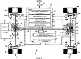
фиг.1 - структурная схема, показывающая общую компоновку устройства управления режимом поворота транспортного средства согласно первому варианту осуществления настоящего изобретения;FIG. 1 is a block diagram showing a general arrangement of a vehicle rotation control apparatus according to a first embodiment of the present invention; FIG.
фиг.2 - структурная схема управления, показывающая, главным образом, управление, производимое устройством управления режимом поворота транспортного средства согласно первому варианту осуществления настоящего изобретения;FIG. 2 is a control block diagram showing mainly control produced by a vehicle rotation control device according to a first embodiment of the present invention;
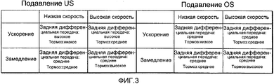
фиг.3 - таблица, показывающая характеристику усиления и ослабления величины управляющего воздействия устройства управления режимом поворота транспортного средства согласно первому варианту осуществления;FIG. 3 is a table showing a characteristic of amplification and attenuation of a magnitude of a control action of a vehicle rotation control apparatus according to a first embodiment;
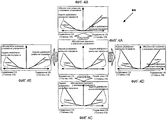
фиг.4A-4E - изображения, показывающие пример характерной схемы управления устройства управления режимом поворота транспортного средства согласно первому варианту осуществления;4A-4E are images showing an example of a representative control circuit of the vehicle rotation control apparatus according to the first embodiment;
фиг.5 - блок-схема последовательности операций, показывающая управление устройства управления режимом поворота транспортного средства согласно первому варианту осуществления;5 is a flowchart showing control of a vehicle rotation control apparatus according to a first embodiment;
фиг.6 - блок-схема последовательности операций, показывающая управление устройства управления режимом поворота транспортного средства согласно первому варианту осуществления и также показывающая подпрограмму управления подавления OS; и6 is a flowchart showing a control of a vehicle rotation control apparatus according to a first embodiment and also showing an OS suppression control subroutine; and
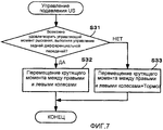
фиг.7 - блок-схема последовательности операций, показывающая управление устройства управления режимом поворота транспортного средства согласно первому варианту осуществления настоящего изобретения, и эта блок-схема последовательности операций способа показывает подпрограмму управления подавления US.7 is a flowchart showing control of a vehicle steering mode control apparatus according to a first embodiment of the present invention, and this method flowchart shows a US suppression control subroutine.
ПОДРОБНОЕ ОПИСАНИЕ ИЗОБРЕТЕНИЯDETAILED DESCRIPTION OF THE INVENTION
Со ссылкой на чертежи, ниже будет пояснен первый вариант осуществления настоящего изобретения. Устройство управления режимом поворота, показанное на фиг.1, применяется в транспортном средстве 1 с приводом на четыре колеса. Выходная мощность двигателя 2, установленного на транспортном средстве 1, передается на правое переднее колесо 8R и левое переднее колесо 8L через коробку передач 3, механизм 4 промежуточной передачи, переднюю дифференциальную передачу 6 и полуоси 7R, 7L. Одновременно выходная мощность двигателя 2, установленного на транспортном средстве 1, передается на правое заднее колесо 14R и левое заднее колесо 14L через механизм 9 гипоидной передачи на стороне передних колес, карданный вал 10, механизм 11 гипоидной передачи на стороне задних колес, заднюю дифференциальную передачу 12 и полуоси 13R, 13L. Более детально эта задняя дифференциальная передача 12 включает в себя механизм 15 перемещения движущей силы для перемещения движущей силы между правым и левым колесами, подробности которого будут описаны позже.With reference to the drawings, a first embodiment of the present invention will be explained below. The rotation control device shown in FIG. 1 is used in a vehicle 1 with a four-wheel drive. The output of the
Передняя дифференциальная передача 6 является дифференциальной передачей типа с индукцией крутящего момента, которая механически ограничивает движение с различной скоростью, производимое между правым 8R и левым колесом 8L, согласно интенсивности крутящего момента, вводимого с двигателя 2.The front differential gear 6 is a torque induction type differential gear that mechanically limits the movement at different speeds between the right 8R and the
Далее, ниже будет описана система привода на стороне заднего колеса 14. На этом заднем колесе 14 предусмотрена дифференциальная передача 12, которая предоставляет возможность движения с различной скоростью, производимого между правым колесом 14R и левым колесом 14L. В этой задней дифференциальной передаче 12 предусмотрен механизм 15 перемещения движущей силы для перемещения движущей силы между правым и левым колесами, посредством которого разница движущей силы, которая должна передаваться на правое колесо 14R и левое колесо 14R, может изменяться надлежащим образом.Next, a drive system on the side of the
На внешней окружности картера 12A этой задней дифференциальной передачи 12 скомпонована коронная шестерня, которая находится в зацеплении с ведущей шестерней 10A, предусмотренной в задней концевой части карданного вала 10. Внутри картера 12A предусмотрен планетарный зубчатый механизм 12B. Посредством этого планетарного зубчатого механизма 12B предоставлена возможность движения с различной скоростью между правым колесом 14R и левым колесом 14L. Соответственно крутящий момент, который был подан с двигателя 2 на коронную шестерню 16 через карданный вал 10 и ведущую шестерню 10A, передается на оба колеса 14R, 14L, наряду с тем, что движение с различной скоростью между правым задним колесом 14R и левым задним колесом 14L допускается механизмом 12B планетарной передачи.A ring gear is arranged on the outer circumference of the
Механизм 15 перемещения движущей силы для перемещения движущей силы между правым и левым колесами включает в себя: механизм 15A коробки скоростей; и механизм 15B передачи крутящего момента со способностью управления регулируемой передачей. Согласно команде, подаваемой с ECU 40 (блока электронного управления), установленного на транспортном средстве 1, разница между движущей силой правого колеса 14R и таковой у левого колеса 14L может изменяться надлежащим образом, согласно состоянию движения транспортного средства. В этой конструкции механизм 15A коробки скоростей увеличивает или уменьшает частоту вращения одного из правого и левого колес (в данном случае частоту вращения левого колеса 14L) и выводит ее на механизм 15B передачи крутящего момента.The driving
Этот механизм 15B передачи крутящего момента типа управления со способностью регулирования привода является механизмом гидравлического многодискового сцепления типа работающего в масляной ванне, допускающим регулирование передачи способности крутящего момента согласно гидравлическому давлению, вводимому из гидравлического узла системы привода, управляемого ECU 40. Этот механизм 15B передачи крутящего момента типа управления со способностью передачи крутящего момента приводится в действие, как изложено ниже. Используя разницу между частотой вращения, которая увеличивается или уменьшается коробкой 15A скоростей, и частотой вращения другого колеса (в настоящем варианте осуществления, правого колеса 14R) среди правого и левого колес, крутящий момент подается и принимается между правым колесом 14R и левым колесом 14L. Вследствие вышеизложенного интенсивность крутящего момента одного колеса увеличивается или уменьшается, а интенсивность крутящего момента другого колеса уменьшается или увеличивается. В этой связи механизм 12B планетарной передачи, механизм 15A коробки скоростей и механизм 15B передачи крутящего момента, описанные выше, широко известны. Поэтому подробные разъяснения конструкций вышеприведенных механизмов здесь опущены. Гидравлическое давление, введенное из гидравлического узла системы привода в механизм 15 перемещения движущей силы, для перемещения движущей силы между правым и левым колесами, управляется контроллером 31 задней дифференциальной передачи. Суть этого управления будет подробно описана позже.This control type
Соответственно, например, в случае, где транспортное средство 1 является движущимся вперед, наряду с тем, что оно поворачивает по часовой стрелке, заданное гидравлическое давление вводится из гидравлического узла системы привода (не показан) в механизм 15 перемещения движущей силы для перемещения движущей силы между правым и левым колесами задней дифференциальной передачи 12. Когда заданное гидравлическое давление передается на правое колесо 14R и крутящий момент уменьшается, правое заднее колесо 14R замедляется. В это время крутящий момент, передаваемый на левое заднее колесо 14L, увеличивается, и левое заднее колесо 14L ускоряется. Соответственно возможно формировать момент рыскания, направление которого - по часовой стрелке, на транспортном средстве 1.Accordingly, for example, in the case where the vehicle 1 is moving forward, while turning it clockwise, a predetermined hydraulic pressure is introduced from the hydraulic unit of the drive system (not shown) into the driving
В этой связи вышеприведенный гидравлический узел системы привода, не показанный на чертеже, включает в себя: аккумулятор; насос с электродвигателем для поддержания давления масла для гидросистем в аккумуляторе при заданном давлении; датчик давления для отслеживания гидравлического давления, нагнетаемого насосом с электродвигателем; клапан с электромагнитным управлением для регулирования гидравлического давления в аккумуляторе, которое уже было отрегулировано насосом с электродвигателем; и клапан переключения направления для переключения гидравлического давления, которое было отрегулировано клапаном с электромагнитным управлением, между заданной гидравлической камерой (не показана) механизма 15 перемещения движущей силы для перемещения движущей силы между правым и левым колесами, и заданной гидравлической камерой (не показана) механизма ограничения движения с различной скоростью для ограничения движения с различной скоростью между передним и задним колесами.In this regard, the above hydraulic unit of the drive system, not shown in the drawing, includes: a battery; a pump with an electric motor to maintain oil pressure for hydraulic systems in the battery at a given pressure; a pressure sensor for monitoring hydraulic pressure pumped by an electric motor pump; a solenoid valve for regulating the hydraulic pressure in the accumulator, which has already been adjusted by a pump with an electric motor; and a direction switching valve for switching a hydraulic pressure that has been adjusted by the solenoid valve between the predetermined hydraulic chamber (not shown) of the driving
Контроллер 31 задней дифференциальной передачи (первый регулятор) является электронным блоком управления, имеющим интерфейс, память и ЦП (центральный процессор, CPU), которые не показаны на чертеже. Контроллер 31 задней дифференциальной передачи приводится в действие, как изложено ниже. Сигнал (сигнал распределения движущей силы), показывающий гидравлическое давление, соответствующее разнице движущей силы между правым задним колесом 14R и левым задним колесом 14L, а также показывающий место назначения вывода гидравлического давления, отправляется в гидравлический узел системы привода. Когда гидравлический узел системы привода, который принял этот разностный сигнал движущей силы, надлежащим образом управляет гидравлическим давлением для механизма 15 перемещения движущей силы ради перемещения движущей силы между правым и левым колесами задней дифференциальной передачи 12, регулируется разница движущей силы между правым задним колесом 14R и левым задним колесом 14L.The rear differential gear controller 31 (first controller) is an electronic control unit having an interface, memory, and a CPU (central processing unit, CPU), which are not shown in the drawing. The differential
Колеса 8L, 8R, 14L, 14R транспортного средства 1 соответственно имеют тормозные устройства 21L, 21R, 22L, 22R. Предусмотрены гидравлические узлы системы управления для независимой подачи гидравлического давления на тормозные устройства 21L, 21R, 22L, 22R. Транспортное средство 1 содержит контроллер 33 тормозных устройств (второй регулятор). Контроллер 33 тормозных устройств является электронным блоком управления, имеющим интерфейс, память и ЦП, которые не показаны на чертеже. Контроллер 33 тормозных устройств посылает сигнал (сигнал увеличения и уменьшения давления торможения), который показывает гидравлическое давление, которое должно увеличиваться и уменьшаться, что касается четырех соответственных тормозных устройств 21L, 21R, 22L, 22R, скомпонованных на колесах 8L, 8R, 14L, 14R, в гидравлический узел системы управления (не показан). Гидравлический узел системы управления, который принял этот сигнал увеличения и уменьшения давления торможения, надлежащим образом управляет гидравлическим давлением, вводимым в тормозное устройство 21L, 21R, 22L, 22R. Этот гидравлический узел тормозной системы включает в себя насос с электродвигателем, клапан с электромагнитным управлением для регулирования гидравлического давления торможения так, что заданное гидравлическое давление может вводиться в каждый тормозной узел 21L, 21R, 22L, 22R согласно направлению, заданному из контроллера 33 тормозных узлов. Как описано выше, контроллер 31 заднего дифференциала и контроллер 33 тормозных узлов присоединены к ECU 40 через сигнальные линии и приводятся в действие согласно управляющему сигналу, посылаемому из ECU 40.The
ECU 40 является электронным блоком управления, имеющим интерфейс, память и ЦП, которые не показаны на чертеже. ECU 40 может считывать результат детектирования, произведенного датчиком 45L, 45R, 46L, 46R скорости транспортного средства (детектором), датчиком 47 угла поворота G, датчиком 48 (детектором) и датчиком 49 угловой скорости рыскания.The
Этот ECU 40 включает в себя часть 41 расчета управляющего момента рыскания, часть 42 оценки недостаточной поворачиваемости/избыточной поворачиваемости (суждения о US/OS) и часть 43 управления движением рыскания (контроллер движения), которые являются программами, записанными в непоказанной памяти. Схема 44 управления движением рыскания, используемая частью 43 управления движением рыскания, записана в этой памяти. Часть 41 расчета управляющего момента рыскания предусмотрена для нахождения управляющего момента рыскания, который является моментом рыскания, который следует добавить так, что транспортное средство 1 может поворачиваться по радиусу поворота, по которому водитель намеревается поворачивать транспортное средство.This
Как показано на фиг.2, эта часть 41 расчета управляющего момента рыскания рассчитывает целевую угловую скорость рыскания (целевое значение корреляции момента рыскания) согласно углу поворота, который измеряется датчиком 47 угла поворота, и скорости транспортного средства, которая детектируется датчиком частоты вращения каждого колеса. Кроме того, когда эта часть 41 расчета управляющего момента рыскания выполняет управление, при котором производится коррекция, посредством сопоставления угловой целевой скорости рыскания с фактической угловой скоростью рыскания, измеренной датчиком 49 угловой скорости рыскания, то есть когда эта часть 41 расчета управляющего момента рыскания выполняет управление с обратной связью согласно фактической угловой скорости рыскания, может рассчитываться управляющий момент рыскания.As shown in FIG. 2, this yaw control
Часть 42 оценки US/OS предусмотрена для вынесения оценки состояния движения транспортного средства 1, которое является поворачивающим. Согласно управляющему моменту рыскания, полученному частью 41 расчета управляющего момента рыскания, а также согласно ускорению в поперечном направлении транспортного средства 1, измеренному G датчиком 49, выносится оценка, находится ли поворачивающее транспортное средство 1 в состоянии (состоянии недостаточной поворачиваемости), в котором формируется недостаточная поворачиваемость (US), находится ли поворачивающее транспортное средство 1 в состоянии (состоянии нейтральной поворачиваемости), в котором фактически не формируется ни недостаточная поворачиваемость (US), ни избыточная поворачиваемость (OS), или находится ли поворачивающее транспортное средство в состоянии (состоянии избыточной поворачиваемости), в котором формируется избыточная поворачиваемость.The US /
Когда часть 43 управления движением рыскания управляет контроллером 31 заднего дифференциала и контроллером 33 тормозных узлов согласно состоянию поворота транспортного средства 1, момент рыскания, соответствующий управляющему моменту рыскания, формируется на транспортном средстве 1. То есть когда управляющий момент рыскания, полученный частью 41 расчета управляющего момента рыскания, результат оценки (состояния поворота транспортного средства 1), произведенного частью 42 оценки US/OS, и ускорение (продольное ускорение) в продольном направлении транспортного средства 1, детектированное (измеренное) G датчиком 49, применяются к схеме 44 управления движением рыскания, получаются значения управления для управления контроллером 31 задней дифференциальной передачи и контроллером 33 тормозных узлов.When the yaw
В этом случае значение управления для контроллера 31 заднего дифференциала является значением, показывающим степень перемещения движущей силы между правым колесом 14R и левым колесом 14L, произведенного механизмом 15 перемещения движущей силы, для перемещения движущей силы между правым и левым колесами задней дифференциальной передачи 12. Более точно, значение управления для контроллера 31 заднего дифференциала является гидравлическим значением механизма 15 перемещения движущей силы для перемещения движущей силы между правым и левым колесами. Значение управления для контроллера 33 тормозных узлов является значением, показывающим степень увеличения и уменьшения тормозной силы каждого тормозного узла 21L, 21R, 22L, 22R. Более точно значение управления для контроллера 33 тормозных узлов является значением увеличения или уменьшения гидравлического давления каждого тормозного узла 21L, 21R, 22L, 22R.In this case, the control value for the rear
Далее, ниже будет пояснена схема 44 управления движением рыскания. Как показано на фиг.4A-4E, схема 44 управления движением рыскания согласно настоящему варианту осуществления состоит из множества схем. Фиг.4A - основная схема. Фиг.4B - схема, выбираемая во время ускорения транспортного средства. Фиг.4C - схема, выбираемая во время замедления транспортного средства. Фиг.4D - схема, выбираемая во время высокоскоростного движения транспортного средства. Фиг.4E - схема, выбираемая во время низкоскоростного движения транспортного средства. Основная компоновка схемы пояснена ниже со ссылкой на фиг.4A, которая представляет вышеприведенные схемы. Ось абсцисс задает степень недостаточной поворачиваемости (US), формируемой на транспортном средстве 1, которая найдена в состоянии поворота транспортного средства 1, то есть которая найдена по управляющему моменту рыскания, полученному частью 41 расчета управляющего момента рыскания и по результату оценки, произведенной частью 42 оценки US/OS. В качестве альтернативы ось абсцисс задает степень избыточной поворачиваемости (OS). С другой стороны, ось ординат задает абсолютное значение у значения управления для контроллера 31 задней дифференциальной передачи и контроллера 33 тормозных устройств. Кроме того, высокая скорость означает скорость, которая является не меньшей, чем заданное значение, а низкая скорость означает скорость, которая является меньшей, чем заданное значение.Next, a yaw
Как показано на фиг.2, схема 44 управления движением рыскания, главным образом, задает область 44A подавления избыточной поворачиваемости и область 44B подавления недостаточной поворачиваемости. В этой области 44A избыточной поворачиваемости область 44A1 управления задним дифференциалом и область 44A2 управления торможением заданы в порядке управляющего момента рыскания, в котором наименьший управляющий момент рыскания установлен первым. В области 44B недостаточной поворачиваемости область 44B1 управления задним дифференциалом и область 44B2 управления торможением заданы в порядке управляющего момента рыскания, в котором наименьший управляющий момент рыскания установлен первым.As shown in FIG. 2, the yaw
В случае, где подавляется движение рыскания транспортного средства 1, то есть в случае, где подавляется избыточная поворачиваемость (OS), формируемая на транспортном средстве 1, часть 43 управления движением рыскания управляет контроллером 31 задней дифференциальной передачи так, что движущая сила колеса (внутреннего колеса поворота), которое является колесом среди правого колеса 14R и левого колеса 14L, расположенным на стороне центра поворота, может увеличиваться. В случае, где подавляется избыточная поворачиваемость (OS), формируемая на транспортном средстве 1, и только в случае, где управляющий момент рыскания управления по-прежнему не может формироваться, даже когда контроллер 31 заднего дифференциала выполняет управление приводом между правым и левым колесами, часть 43 управления движением рыскания управляет контроллером 33 тормозных устройств так, что тормозная сила внешнего колеса поворота может быть большей, чем тормозная сила внутреннего колеса поворота.In the case where the yaw movement of the vehicle 1 is suppressed, that is, in the case where the oversteer (OS) generated on the vehicle 1 is suppressed, the yaw
С другой стороны, в случае, где облегчается движение рыскания транспортного средства 1, то есть в случае, где подавляется недостаточная поворачиваемость (US), формируемая на транспортном средстве 1, часть 43 управления движением рыскания управляет контроллером 31 задней дифференциальной передачи так, что может увеличиваться движущая сила колеса (внешнего колеса поворота) на стороне, противоположной внутреннему колесу поворота среди правого колеса 14R и левого колеса 14L. В случае, где подавляется недостаточная поворачиваемость (US), формируемая на транспортном средстве 1, и только в случае, где управляющий момент рыскания по-прежнему не может формироваться, даже когда контроллер 31 заднего дифференциала выполняет управление приводом между правым и левым колесами, часть 43 управления движением рыскания управляет контроллером 33 тормозных устройств так, что тормозная сила внутреннего колеса поворота может быть большей, чем тормозная сила внешнего колеса поворота.On the other hand, in a case where yaw movement of the vehicle 1 is facilitated, that is, in a case where understeer (US) generated on the vehicle 1 is suppressed, the yaw
То есть в случае подавления движения рыскания транспортного средства (во время формирования OS) часть 43 управления движением рыскания распределяет величину управляющего воздействия на контроллер 31 задней дифференциальной передачи и контроллер 33 тормозных устройств, и, в то время как контроллер 31 задней дифференциальной передачи управляется так, что движущая сила внутреннего колеса поворота может увеличиваться, контроллер 33 тормозных устройств управляется так, что может увеличиваться тормозная сила внешнего колеса поворота. В случае содействия движению рыскания транспортного средства (во время формирования US) часть 43 управления движением рыскания распределяет величину управляющего воздействия на контроллер 31 задней дифференциальной передачи и контроллер 33 тормозных устройств, и, в то время как контроллер 31 задней дифференциальной передачи управляется так, что может увеличиваться движущая сила внешнего колеса поворота, контроллер 33 тормозных устройств управляется так, что может увеличиваться тормозная сила внутреннего колеса поворота. Одновременно в случае содействия движению рыскания транспортного средства (во время формирования US), коэффициент величины управляющего воздействия, которая должна распределяться на контроллер 31 заднего дифференциала, делается более высоким, чем коэффициент величины управляющего воздействия, которая должна распределяться в случае, когда движение рыскания транспортного средства подавляется (во время формирования OS). В случае подавления движения рыскания транспортного средства (во время формирования OS) коэффициент величины управляющего воздействия, которая должна распределяться на контроллер 33 тормозных устройств, делается более высоким, чем коэффициент величины управляющего воздействия, которая должна распределяться в случае, когда движение рыскания транспортного средства облегчается (во время формирования US). Предусмотрена схема 44 управления движением рыскания, имеющая вышеприведенную характеристику управления.That is, in the case of suppressing a vehicle yawing motion (during OS formation), the yawing
Выше описана основная характеристика управления в случае использования схемы 44 управления движением рыскания. Схема 44 движения рыскания изложена детально не только для случая недостаточной поворачиваемости (US) и избыточной поворачиваемости, но также для случая, в котором абсолютное значение управления управляется, будучи изменяемым согласно ускорению, замедлению и скорости транспортного средства, а величина распределения управляющего воздействия между механизмом 15 перемещения движущей силы для перемещения движущей силы между правым и левым колесами, и тормозным узлом управляется, будучи изменяемой, как показано на фиг.3 и 4A-4E. То есть распределение величины управляющего воздействия между контроллером 31 заднего дифференциала и контроллером 33 тормозных узлов может изменяться согласно ускорению, замедлению и скорости транспортного средства. Характеристика распределения величины управляющего воздействия установлена заранее согласно схеме 44 управления движением рыскания, показанной на фиг.4A-4E.The main control characteristic in the case of using the yaw
В случае, когда результатом детектирования, произведенного G датчиком 49, является ускорение (показано на фиг.4B), схема 44 управления движением рыскания делает коэффициент величины управляющего воздействия, распределяемой на контроллер 31 заднего дифференциала, более высоким, чем коэффициент в случае замедления (показано на фиг.4C). В случае, когда результатом детектирования, произведенного G датчиком 49, является замедление (показано на фиг.4C), схема 44 управления движением рыскания делает коэффициент величины управляющего воздействия, распределяемой на контроллер 33 тормозных узлов, более высоким, чем коэффициент в случае ускорения (показано на фиг.4B). В случае, когда результатом детектирования, произведенного датчиком частоты вращения колеса, является низкая скорость (показано на фиг.4E), коэффициент величины управляющего воздействия, распределенной на контроллер 31 заднего дифференциала, делается более высоким, чем коэффициент в случае высокой частоты вращения (показано на фиг.4D). В случае, где результатом детектирования, произведенного датчиком частоты вращения колеса, является высокая скорость (показано на фиг.4E), коэффициент величины управляющего воздействия, распределенной на контроллер 33 тормозных узлов, делается более высоким, чем коэффициент в случае низкой частоты вращения (показано на фиг.4E). Характеристика задана, как описано выше. Характеристика интенсивности величины управляющего воздействия показана на фиг.3. Задняя дифференциальная передача показывает контроллер 31 заднего дифференциала (механизм 15 перемещения движущей силы для перемещения движущей силы между правым и левым колесами). Тормоз показывает контроллер 33 тормозного узла 33 (тормозное устройство 21L, 21R, 22L, 22R). Кроме того, «Высокое», «Среднее» и «Низкое» являются амплитудами абсолютных значений устройств, то есть «Высокое», «Среднее» и «Низкое» являются значениями гидравлического давления устройств. Эти значения предварительно сохранены в ECU 40.In the case where the result of the detection performed by the
Устройство управления режимом поворота транспортного средства согласно варианту осуществления настоящего изобретения составлено, как описано выше. Поэтому оно демонстрирует следующее действие и результат. Суть действия и результата будет пояснена со ссылкой на блок-схемы последовательности операций, показанные на фиг.5-7.The vehicle rotation control device according to an embodiment of the present invention is configured as described above. Therefore, it demonstrates the following action and result. The essence of the action and the result will be explained with reference to the flowcharts shown in Fig.5-7.
Как показано на фиг.5, на этапе S11 часть 41 расчета управляющего момента рыскания считывает угол поворота, детектированный датчиком 47 рулевого управления, скорость транспортного средства, детектированную каждым датчиком 45 скорости транспортного средства, и фактическую угловую скорость рыскания, детектированную датчиком 48 угловой скорости рыскания. Одновременно часть 42 суждения о US/OS считывает поперечное ускорение, детектированное G датчиком 49.As shown in FIG. 5, in step S11, the yaw control
На этапе S12 часть 41 расчета управляющего момента рыскания рассчитывает целевую угловую скорость рыскания согласно углу поворота и скорости транспортного средства, которые были считаны раньше. Когда целевая угловая скорость рыскания и фактическая угловая скорость рыскания сравниваются друг с другом, часть 41 расчета управляющего момента рыскания рассчитывает управляющий момент рыскания. После того на этапе S13 выбирается схема (показанная на фиг.4A-4E), соответствующая скорости, а также ускорению и замедлению.In step S12, the yaw control
На этапах S14 и S16 согласно управляющему моменту рыскания и поперечному ускорению часть 42 суждения о US/OS выносит суждение, формируется ли на транспортном средстве 1 избыточная поворачиваемость (OS), формируется ли на транспортном средстве 1 недостаточная поворачиваемость (US), или, по существу, не формируется ни недостаточная поворачиваемость (US), ни избыточная поворачиваемость (OS). В случае, когда часть 42 суждения о US/OS выносит суждение, что транспортное средство 1 находится в состоянии, в котором была сформирована избыточная поворачиваемость, программа переходит на этап S15, и выполняется управление подавления OS, которое является подпрограммой. Когда часть 42 суждения о US/OS выносит суждение, на этапе 16, что формируется недостаточная поворачиваемость, программа переходит к этапу S17, и выполняется управление подавления US, которое является подпрограммой. В случае, когда часть 42 суждения о US/OS выносит суждение, что не формируется ни недостаточная поворачиваемость, ни избыточная поворачиваемость, программа возвращает управление как есть.In steps S14 and S16, according to the yaw control moment and lateral acceleration, the US /
Далее, ниже будут пояснены управление подавления OS и управление подавления US, которые являются подпрограммами. При управлении подавления OS, показанном на фиг.6, когда управление перемещением крутящего момента (управление задней дифференциальной передачей), производимое между правым задним колесом 14R и левым задним колесом 14L контроллером 31 задней дифференциальной передачи, выполняется контроллером 31 задней дифференциальной передачи на этапе S21, выносится суждение, может или нет быть удовлетворен управляющий момент рыскания.Next, OS suppression control and US suppression control, which are routines, will be explained below. In the OS suppression control shown in FIG. 6, when the torque movement control (rear differential gear control) between the right rear wheel 14R and the left rear wheel 14L by the rear
В этом случае, когда выносится суждение, что управляющий момент рыскания может быть удовлетворен выполнением управления задней дифференциальной передачей, на этапе S22, управление задним дифференциалом выполняется согласно характеристике выбранной схемы. Вследствие вышеизложенного регулируется разница в крутящем моменте между правым задним колесом 14R и левым задним колесом 14L так, что избыточная поворачиваемость, формируемая на транспортном средстве 1, может подавляться.In this case, when it is judged that the yaw control moment can be satisfied by performing the rear differential gear control, in step S22, the rear differential control is performed according to the characteristic of the selected circuit. As a result of the foregoing, the torque difference between the right rear wheel 14R and the left rear wheel 14L is adjusted so that oversteer generated on the vehicle 1 can be suppressed.
С другой стороны, в случае, когда выносится суждение, что управляющий момент рыскания не может быть удовлетворен, даже если выполняется управление задней дифференциальной передачей, на этапе S23, в дополнение к управлению задней дифференциальной передачей, соответствующему характеристике выбранной схемы, выполняется управление (управление тормозом), выполняемое контроллером 33 тормозных устройств, при котором тормозная сила, подаваемая на внешнее колесо поворота, делается более сильной, чем тормозная сила, подаваемая на внутреннее колесо поворота. Вследствие вышеизложенного подавляется избыточная поворачиваемость, формируемая на транспортном средстве 1.On the other hand, in the case where it is judged that the yaw control torque cannot be satisfied even if the rear differential gear is controlled, in step S23, in addition to controlling the rear differential gear corresponding to the characteristic of the selected circuit, control is performed (brake control ) performed by the
Управление подавления US, показанное на фиг.7, будет пояснено, как изложено ниже. На этапе S31, когда выполняется управление задней дифференциальной передачей, выносится суждение, может или нет удовлетворяться управляющий момент рыскания. В этом случае, когда было вынесено суждение, что управляющий момент рыскания может быть удовлетворен выполнением управления задней дифференциальной передачей, на этапе S32, выполняется управление задней дифференциальной передачей, соответствующее характеристике выбранной схемы так, что может регулироваться разница крутящего момента между правым задним колесом 14R и левым задним колесом 14L. Таким способом избыточная поворачиваемость, формируемая на транспортном средстве 1, подавляется.The US suppression control shown in FIG. 7 will be explained as follows. In step S31, when the reverse differential gear control is performed, a judgment is made whether or not the yaw control moment can be satisfied. In this case, when it has been judged that the yaw control torque may be satisfied by performing the rear differential gear control, in step S32, the rear differential gear control corresponding to the characteristic of the selected circuit is performed so that the torque difference between the right rear wheel 14R and left rear wheel 14L. In this way, oversteer generated on the vehicle 1 is suppressed.
В случае, когда было вынесено суждение, что управляющий момент не может быть удовлетворен, когда выполняется только управление задней дифференциальной передачей, на этапе S33, в дополнение к управлению задней дифференциальной передачей выполняется управление тормозом, соответствующее характеристике выбранной схемы так, что недостаточная поворачиваемость, формируемая на транспортном средстве 1, может подавляться.In the case where it has been judged that the control torque cannot be satisfied when only the rear differential gear control is performed, in step S33, in addition to the rear differential gear control, a brake control corresponding to the characteristic of the selected circuit is performed so that insufficient understeer generated on vehicle 1, can be suppressed.
Как описано выше, в настоящем варианте осуществления, в случае подавления движения рыскания транспортного средства 1, движущая сила внутреннего колеса поворота увеличивается, и увеличивается тормозная сила внешнего колеса поворота. В случае содействия движению рыскания транспортного средства движущая сила внешнего колеса поворота увеличивается, и увеличивается тормозная сила внутреннего колеса поворота. Соответственно может улучшаться поворотливость транспортного средства. Во время подавления движения рыскания и во время содействия движению рыскания величина распределения управляющего воздействия между контроллером 31 задней дифференциальной передачи и контроллером 33 тормозных устройств управляется, будучи изменяемой. Поэтому по сравнению со случаем, в котором величина распределения управляющего воздействия постоянна, возможно, чтобы случай по настоящему варианту осуществления гибко справлялся с состоянием транспортного средства. Соответственно впечатление от вождения может улучшаться.As described above, in the present embodiment, in the case of suppressing a yawing movement of the vehicle 1, the driving force of the inner turning wheel is increased, and the braking force of the external turning wheel is increased. In the case of facilitating the yawing movement of the vehicle, the driving force of the outer turning wheel increases and the braking force of the inner turning wheel increases. Accordingly, vehicle agility can be improved. During yaw suppression and during yaw assist, the amount of control action distribution between the rear
То есть в случае содействия движению рыскания транспортного средства (во время формирования US) коэффициент величины управляющего воздействия, распределяемой на контроллер 31 задней дифференциальной передачи, делается более высоким, чем коэффициент в случае подавления движения рыскания транспортного средства (во время формирования OS). Поэтому движущая сила внешнего колеса поворота, нагрузка соприкосновения с землей которого является интенсивной, увеличивается так, что управление движением рыскания может эффективно выполняться. В случае подавления движения рыскания транспортного средства 1 (во время формирования OS) коэффициент величины управляющего воздействия, распределяемой на контроллер 33 тормозных узлов, делается более высоким, чем коэффициент в случае содействия движению рыскания транспортного средства 1 (во время формирования US). Поэтому движущая сила внешнего колеса поворота, нагрузка соприкосновения с землей которого является интенсивной, увеличивается так, что управление движением рыскания может эффективно выполняться, а поворотливость может стабилизироваться.That is, in the case of facilitating vehicle yaw movement (during US formation), the coefficient of the amount of control distributed to the rear
В настоящем варианте осуществления в случае, когда на этапе S13 согласно фиг.5 выбирается схема, показанная на фиг.4B, коэффициент величины управляющего воздействия, распределяемой на контроллер 31 заднего дифференциала, делается более высоким, чем коэффициент случая замедления, показанного на фиг.4C. Поэтому во время ускорения, при котором нагрузка соприкосновения с землей колеса увеличивается, движущая сила еще более увеличивается так, что управление движением рыскания может выполняться более эффективно. Соответственно наряду с тем, что ощущение замедления во время ускорения уменьшается, поворотливость может стабилизироваться, а впечатление от вождения может еще больше улучшаться. Во время замедления транспортного средства 1 и в случае, когда на этапе S13, показанном на фиг.5, выбрана схема, показанная на фиг.4C, коэффициент величины управляющего воздействия, распределяемой на контроллер 33 тормозных узлов, делается более высоким, чем коэффициент в случае ускорения, показанном на фиг.4C. Поэтому даже когда нагрузка колеса уменьшается вследствие замедления, уменьшение поперечной силы колеса, вызванное увеличением разницы движущей силы между правым колесом и левым колесом, может подавляться. Соответственно поворотливость во время замедления может стабилизироваться.In the present embodiment, when the circuit shown in FIG. 4B is selected in step S13 of FIG. 5, the coefficient of the amount of control distributed to the rear
В настоящем варианте осуществления, когда транспортное средство является движущимся на низкой скорости, и на этапе S13, показанном на фиг.5, выбирается схема, показанная на фиг.4E, коэффициент величины управляющего воздействия, распределяемой на контроллер 31 заднего дифференциала, делается более высоким, чем коэффициент случая высокой скорости, показанного на фиг.4D. Когда транспортное средство является движущимся на высокой скорости, и на этапе S13, показанном на фиг.5, выбирается схема, показанная на фиг.4D, коэффициент величины управляющего воздействия, распределяемой на контроллер 33 тормозного узла, делается более высоким, чем коэффициент случая низкой скорости, показанного на фиг.4E. Поэтому наряду с тем, что уменьшается ощущение замедления, вызванное чрезмерно сильной тормозной силой, недостаточная поворачиваемость и избыточная поворачиваемость могут подавляться надлежащим образом, а поворотливость транспортного средства может улучшаться.In the present embodiment, when the vehicle is moving at a low speed, and in step S13 shown in FIG. 5, the circuit shown in FIG. 4E is selected, the coefficient of the amount of control applied to the rear
Выше были пояснены варианты осуществления настоящего изобретения. Однако должно быть отмечено, что настоящее изобретение не ограничено вышеприведенным конкретным вариантом осуществления. Могут быть внесены изменения, не выходя из сущности и объема настоящего изобретения.Embodiments of the present invention have been explained above. However, it should be noted that the present invention is not limited to the above specific embodiment. Changes may be made without departing from the spirit and scope of the present invention.
В вышеприведенном варианте осуществления передняя дифференциальная передача 6 является дифференциальной передачей типа с индукцией крутящего момента, которая механически ограничивает движение с различными скоростями, производимое между правым 8R и левым колесом 8L, согласно интенсивности крутящего момента, введенного с двигателя 2. Однако должно быть отмечено, что настоящее изобретение не ограничено вышеприведенным отдельным вариантом осуществления. Например, механизм 15 перемещения движущей силы для перемещения движущей силы между правым и левым колесами, может быть установлен не только в задней дифференциальной передаче 12, но также в передней дифференциальной передаче 6.In the above embodiment, the front differential gear 6 is a torque induction type differential gear that mechanically restricts the movement at different speeds between the right 8R and the
В качестве альтернативы механизм 15 перемещения движущей силы для перемещения движущей силы между правым и левым колесами, может быть установлен только в передней дифференциальной передаче 6.Alternatively, the driving
В вышеприведенном варианте осуществления пояснения произведены в отношении случая, в котором транспортное средство 1 является транспортным средством с приводом на четыре колеса. Однако транспортное средство 1 не ограничивается главным образом, транспортным средством с приводом на четыре колеса. Транспортное средство 1 может быть транспортным средством с приводом на передние колеса. В качестве альтернативы транспортное средство 1 может быть транспортным средством с приводом на задние колеса.In the above embodiment, explanations are made regarding the case in which the vehicle 1 is a four-wheel drive vehicle. However, the vehicle 1 is not limited mainly to a four-wheel drive vehicle. The vehicle 1 may be a front-wheel drive vehicle. Alternatively, the vehicle 1 may be a rear-wheel drive vehicle.
В вышеприведенном варианте осуществления пояснения приведены в отношении случая, в котором, когда контроллер 31 заднего дифференциала управляет механизмом 15 перемещения движущей силы для перемещения движущей силы между правым и левым колесами, и регулируется разница между крутящим моментом, передаваемым с двигателя 1 на правое заднее колесо 14R, и крутящим моментом, передаваемым с двигателя 1 на левое заднее колесо 14L. Однако должно быть отмечено, что настоящее изобретение не ограничено вышеприведенным отдельным вариантом осуществления. Например, могут независимо регулироваться движущие силы электродвигателей, которые установлены соответственно на стороне передних колес или стороне задних колес. В этой связи, в этом случае, иные чем электродвигатель, другие источники привода, такие как двигатель, могут установлены на транспортном средстве.In the above embodiment, explanations are provided regarding a case in which when the rear
Вместо механизма 15 перемещения движущей силы для перемещения движущей силы между правым и левым колесами, может использоваться механизм распределения движущей силы между правым и левым колесами. Например, может быть принято следующее построение. Когда механизмы сцепления соответственно скомпонованы на правом и левом колесах, и регулируются силы зажима этих механизмов сцепления, интенсивности движущих сил, передаваемых на правое и левое колеса, могут изменяться. Кроме того, это построение может применяться к стороне задних колес или стороне передних колес.Instead of the driving
В вышеприведенном варианте осуществления суждение о недостаточной поворачиваемости/избыточной поворачиваемости производится согласно управляющему моменту рыскания, полученному частью 41 расчета управляющего момента рыскания, и согласно ускорению в поперечном направлении транспортного средства 1, измеренному G датчиком 49. Однако должно быть отмечено, что настоящее изобретение не ограничено вышеприведенным отдельным вариантом осуществления. При условии, что возможно выносить суждение о состоянии поворота транспортного средства, может перениматься любая конструкция.In the above embodiment, the understeer / oversteer is judged according to the yaw control moment obtained by the
В вышеприведенном варианте осуществления информация о скорости детектируется датчиками 45L, 45R, 46L, 46R скорости транспортного средства. Однако должно быть отмечено, что настоящее изобретение не ограничено вышеприведенным отдельным вариантом осуществления. Например, может приниматься следующее построение. Низкоскоростной поворот/высокоскоростной поворот оценивается по информации детектирования, посланной с датчика 47 угла поворота рулевого колеса, и схема выбирается согласно таким образом оцененному значению.In the above embodiment, speed information is detected by
В вышеприведенном варианте осуществления ускорение транспортного средства в продольном направлении детектируется G датчиком 49. Однако настоящее изобретение не ограничено вышеприведенным отдельным вариантом осуществления. Например, продольное ускорение оценивается, когда дифференцируется скорость транспортного средства, и схема может выбираться по этому оцененному значению. В качестве альтернативы, когда продольное ускорение оценивается по выходному крутящему моменту двигателя 2, общей степени снижения передачи 3 и тормозному моменту тормозного узла 21L, 21R, 22L, 22R, схема может выбираться согласно таким образом оцененному значению.In the above embodiment, vehicle acceleration in the longitudinal direction is detected by the
В вышеприведенном варианте осуществления механизм 19 ограничения дифференциала для ограничения дифференциала между передним и задним колесами принадлежит к зубчатому типу. Однако настоящее изобретение не ограничено вышеприведенным отдельным вариантом осуществления. При условии, что он имеет ту же функцию, может использоваться любой тип механизма ограничения дифференциала.In the above embodiment, the differential limiting mechanism 19 for limiting the differential between the front and rear wheels is of the gear type. However, the present invention is not limited to the above separate embodiment. Provided that it has the same function, any type of differential limitation mechanism can be used.
Claims (3)
Applications Claiming Priority (2)
| Application Number | Priority Date | Filing Date | Title |
|---|---|---|---|
| JP2007179646A JP4179392B1 (en) | 2007-07-09 | 2007-07-09 | Vehicle turning behavior control device |
| JP2007-179646 | 2007-07-09 |
Publications (2)
| Publication Number | Publication Date |
|---|---|
| RU2008110647A RU2008110647A (en) | 2009-09-27 |
| RU2388631C2 true RU2388631C2 (en) | 2010-05-10 |
Family
ID=39870146
Family Applications (1)
| Application Number | Title | Priority Date | Filing Date |
|---|---|---|---|
| RU2008110647/11A RU2388631C2 (en) | 2007-07-09 | 2008-03-19 | Device to control vehicle turning |
Country Status (6)
| Country | Link |
|---|---|
| US (1) | US7761215B2 (en) |
| EP (1) | EP2014530B1 (en) |
| JP (1) | JP4179392B1 (en) |
| KR (1) | KR100905190B1 (en) |
| CN (1) | CN101342904B (en) |
| RU (1) | RU2388631C2 (en) |
Cited By (2)
| Publication number | Priority date | Publication date | Assignee | Title |
|---|---|---|---|---|
| US9494923B2 (en) | 2010-09-14 | 2016-11-15 | Khalil Abu Al-Rubb | Electro-mechanical interface |
| RU2747827C1 (en) * | 2019-10-15 | 2021-05-14 | Тойота Дзидося Кабусики Кайся | Vehicle control system and vehicle control device for autonomous vehicle |
Families Citing this family (18)
| Publication number | Priority date | Publication date | Assignee | Title |
|---|---|---|---|---|
| DE102006031511A1 (en) * | 2006-07-07 | 2008-01-17 | Robert Bosch Gmbh | Method for compensating the braking deceleration in a vehicle control |
| JP4313828B2 (en) * | 2007-05-31 | 2009-08-12 | 三菱自動車工業株式会社 | Left / right driving force distribution device |
| JP4179391B1 (en) | 2007-07-09 | 2008-11-12 | 三菱自動車工業株式会社 | Vehicle turning behavior control device |
| JP5138624B2 (en) * | 2009-03-18 | 2013-02-06 | 日立オートモティブシステムズ株式会社 | Vehicle behavior control device |
| DE102010027978A1 (en) * | 2010-04-20 | 2011-10-20 | Robert Bosch Gmbh | Driver assistance system and method for setting a driver assistance system |
| JP5810692B2 (en) * | 2011-07-08 | 2015-11-11 | 三菱自動車工業株式会社 | Vehicle turning behavior control device |
| JP5917906B2 (en) * | 2011-12-20 | 2016-05-18 | トヨタ自動車株式会社 | Vehicle travel support device |
| JP5912505B2 (en) * | 2011-12-20 | 2016-04-27 | トヨタ自動車株式会社 | Vehicle travel support device |
| JP5970322B2 (en) * | 2012-10-01 | 2016-08-17 | 日立オートモティブシステムズ株式会社 | Vehicle motion control device |
| US9376101B2 (en) * | 2013-08-28 | 2016-06-28 | Continental Automotive Systems, Inc. | All-wheel drive torque vectoring by electronic brake system control |
| WO2017044757A1 (en) * | 2015-09-13 | 2017-03-16 | Gm Global Technology Operations, Llc | Automotive vehicle actuator control system |
| WO2017077795A1 (en) * | 2015-11-06 | 2017-05-11 | 株式会社アドヴィックス | Vehicle travel assistance system |
| JP6648495B2 (en) * | 2015-11-10 | 2020-02-14 | アイシン精機株式会社 | Vehicle drive system |
| JP6520874B2 (en) * | 2016-09-12 | 2019-05-29 | トヨタ自動車株式会社 | Vehicle control device |
| CN108116270B (en) * | 2016-11-30 | 2020-07-10 | 比亚迪股份有限公司 | Vehicle instability control method, vehicle instability control device and vehicle |
| JP6790971B2 (en) * | 2017-04-03 | 2020-11-25 | トヨタ自動車株式会社 | Vehicle braking device |
| JP6969440B2 (en) * | 2018-02-26 | 2021-11-24 | トヨタ自動車株式会社 | Vehicle driving support device |
| KR102659235B1 (en) * | 2019-04-11 | 2024-04-19 | 현대자동차주식회사 | Control method for electric limited slip differential |
Family Cites Families (23)
| Publication number | Priority date | Publication date | Assignee | Title |
|---|---|---|---|---|
| JP2623905B2 (en) * | 1990-04-20 | 1997-06-25 | 日産自動車株式会社 | Drive system clutch control device for vehicles |
| JP2853474B2 (en) * | 1992-08-24 | 1999-02-03 | トヨタ自動車株式会社 | Driving force distribution device for four-wheel drive vehicles |
| US5541840A (en) * | 1993-06-25 | 1996-07-30 | Chrysler Corporation | Hand held automotive diagnostic service tool |
| JPH07101262A (en) * | 1993-10-04 | 1995-04-18 | Nissan Motor Co Ltd | Torque distribution control device |
| JP3274758B2 (en) | 1993-12-17 | 2002-04-15 | マツダ株式会社 | Driving force distribution control device for automobile |
| JP3303605B2 (en) * | 1995-05-17 | 2002-07-22 | トヨタ自動車株式会社 | Vehicle behavior control device |
| TW330182B (en) | 1995-09-26 | 1998-04-21 | Honda Motor Co Ltd | Process for controlling yaw moment in a vehicle |
| JP3183124B2 (en) * | 1995-09-28 | 2001-07-03 | 三菱自動車工業株式会社 | Vehicle turning behavior control device |
| EP0844129B1 (en) * | 1996-11-13 | 2003-08-27 | Honda Giken Kogyo Kabushiki Kaisha | Yaw moment control system in vehicle |
| US6035251A (en) * | 1997-11-10 | 2000-03-07 | General Motors Corporation | Brake system control method employing yaw rate and ship angle control |
| JP4119020B2 (en) * | 1998-10-28 | 2008-07-16 | 本田技研工業株式会社 | Vehicle control device |
| JP4071400B2 (en) * | 1999-09-07 | 2008-04-02 | 本田技研工業株式会社 | Vehicle cooperative control device |
| JP2004075013A (en) | 2002-08-22 | 2004-03-11 | Denso Corp | Vehicle control device |
| JP3870911B2 (en) * | 2003-02-10 | 2007-01-24 | 日産自動車株式会社 | Lane departure prevention device |
| JP2005047437A (en) * | 2003-07-30 | 2005-02-24 | Advics:Kk | Movement control device for vehicle |
| JP2005104346A (en) * | 2003-09-30 | 2005-04-21 | Mitsubishi Fuso Truck & Bus Corp | Learning method and device of stability factor of vehicle, and control device for vehicle |
| JP4391304B2 (en) * | 2004-04-23 | 2009-12-24 | 日産自動車株式会社 | Deceleration control device |
| JP4114657B2 (en) * | 2004-10-25 | 2008-07-09 | 三菱自動車工業株式会社 | Vehicle turning behavior control device |
| JP4615321B2 (en) * | 2005-01-26 | 2011-01-19 | 富士重工業株式会社 | Control device for four-wheel drive vehicle |
| JP4618105B2 (en) * | 2005-11-11 | 2011-01-26 | 三菱自動車工業株式会社 | Vehicle turning behavior control device |
| DE102005058945A1 (en) | 2005-12-09 | 2007-06-14 | Zf Friedrichshafen Ag | Method for operating a drive train of a vehicle |
| WO2008092003A2 (en) * | 2007-01-25 | 2008-07-31 | Honda Motor Co., Ltd. | Vehicle systems control for improving stability |
| JP4179391B1 (en) * | 2007-07-09 | 2008-11-12 | 三菱自動車工業株式会社 | Vehicle turning behavior control device |
-
2007
- 2007-07-09 JP JP2007179646A patent/JP4179392B1/en active Active
-
2008
- 2008-02-18 KR KR1020080014346A patent/KR100905190B1/en active IP Right Grant
- 2008-03-19 RU RU2008110647/11A patent/RU2388631C2/en active
- 2008-03-19 US US12/051,577 patent/US7761215B2/en active Active
- 2008-03-20 EP EP20080153158 patent/EP2014530B1/en active Active
- 2008-03-20 CN CN2008100871685A patent/CN101342904B/en active Active
Cited By (3)
| Publication number | Priority date | Publication date | Assignee | Title |
|---|---|---|---|---|
| US9494923B2 (en) | 2010-09-14 | 2016-11-15 | Khalil Abu Al-Rubb | Electro-mechanical interface |
| RU2605003C2 (en) * | 2010-09-14 | 2016-12-20 | АЛЬ-РУББ Халил АБУ | Electromechanical interface |
| RU2747827C1 (en) * | 2019-10-15 | 2021-05-14 | Тойота Дзидося Кабусики Кайся | Vehicle control system and vehicle control device for autonomous vehicle |
Also Published As
| Publication number | Publication date |
|---|---|
| KR100905190B1 (en) | 2009-06-29 |
| CN101342904B (en) | 2012-11-28 |
| CN101342904A (en) | 2009-01-14 |
| EP2014530A2 (en) | 2009-01-14 |
| EP2014530A3 (en) | 2009-01-28 |
| EP2014530B1 (en) | 2015-05-13 |
| KR20090005949A (en) | 2009-01-14 |
| US7761215B2 (en) | 2010-07-20 |
| JP4179392B1 (en) | 2008-11-12 |
| US20090018741A1 (en) | 2009-01-15 |
| RU2008110647A (en) | 2009-09-27 |
| JP2009012708A (en) | 2009-01-22 |
Similar Documents
| Publication | Publication Date | Title |
|---|---|---|
| RU2388631C2 (en) | Device to control vehicle turning | |
| RU2384438C2 (en) | Device to control vehicle turn | |
| JP4618105B2 (en) | Vehicle turning behavior control device | |
| JP4267495B2 (en) | Driving force control method for four-wheel drive vehicle | |
| US7073621B2 (en) | Vehicle steering control device | |
| KR100622228B1 (en) | Driving power control device between right-left wheel for vehicles | |
| KR100918163B1 (en) | Driving force distribution controller | |
| JP4554252B2 (en) | Control method for four-wheel drive vehicle | |
| US20040064239A1 (en) | Power distribution control apparatus for four wheel drive vehicle | |
| KR100468493B1 (en) | Method for operating electric power steering system of automobile | |
| US7657357B2 (en) | Vehicle motion control device | |
| JP2012035698A (en) | Brake control apparatus of vehicle | |
| JP2009107382A (en) | Driving force distributing device and control method of the same | |
| JP2007320502A (en) | Multi-axle vehicle and its steering control device | |
| JP2005289161A (en) | Driving force control method of 4-wheel drive vehicle | |
| JP5040013B2 (en) | Vehicle turning behavior control device | |
| JP4895043B2 (en) | Vehicle driving force control device | |
| JP5090669B2 (en) | 4-wheel drive vehicle behavior stabilization control method | |
| JP4298564B2 (en) | Driving force control method for four-wheel drive vehicle | |
| JP4993105B2 (en) | Vehicle behavior control device | |
| JP5083526B2 (en) | Vehicle driving force control device | |
| JP2005289162A5 (en) |
Legal Events
| Date | Code | Title | Description |
|---|---|---|---|
| PD4A | Correction of name of patent owner |