RU2376658C2 - Recording medium and method and device for recording data onto recording medium - Google Patents
Recording medium and method and device for recording data onto recording medium Download PDFInfo
- Publication number
- RU2376658C2 RU2376658C2 RU2006136029/28A RU2006136029A RU2376658C2 RU 2376658 C2 RU2376658 C2 RU 2376658C2 RU 2006136029/28 A RU2006136029/28 A RU 2006136029/28A RU 2006136029 A RU2006136029 A RU 2006136029A RU 2376658 C2 RU2376658 C2 RU 2376658C2
- Authority
- RU
- Russia
- Prior art keywords
- recording medium
- area
- recording
- opc
- data
- Prior art date
Links
Images
Classifications
-
- G—PHYSICS
- G11—INFORMATION STORAGE
- G11B—INFORMATION STORAGE BASED ON RELATIVE MOVEMENT BETWEEN RECORD CARRIER AND TRANSDUCER
- G11B7/00—Recording or reproducing by optical means, e.g. recording using a thermal beam of optical radiation by modifying optical properties or the physical structure, reproducing using an optical beam at lower power by sensing optical properties; Record carriers therefor
- G11B7/007—Arrangement of the information on the record carrier, e.g. form of tracks, actual track shape, e.g. wobbled, or cross-section, e.g. v-shaped; Sequential information structures, e.g. sectoring or header formats within a track
- G11B7/00736—Auxiliary data, e.g. lead-in, lead-out, Power Calibration Area [PCA], Burst Cutting Area [BCA], control information
-
- G—PHYSICS
- G11—INFORMATION STORAGE
- G11B—INFORMATION STORAGE BASED ON RELATIVE MOVEMENT BETWEEN RECORD CARRIER AND TRANSDUCER
- G11B7/00—Recording or reproducing by optical means, e.g. recording using a thermal beam of optical radiation by modifying optical properties or the physical structure, reproducing using an optical beam at lower power by sensing optical properties; Record carriers therefor
- G11B7/12—Heads, e.g. forming of the optical beam spot or modulation of the optical beam
- G11B7/125—Optical beam sources therefor, e.g. laser control circuitry specially adapted for optical storage devices; Modulators, e.g. means for controlling the size or intensity of optical spots or optical traces
- G11B7/126—Circuits, methods or arrangements for laser control or stabilisation
- G11B7/1267—Power calibration
-
- G—PHYSICS
- G11—INFORMATION STORAGE
- G11B—INFORMATION STORAGE BASED ON RELATIVE MOVEMENT BETWEEN RECORD CARRIER AND TRANSDUCER
- G11B7/00—Recording or reproducing by optical means, e.g. recording using a thermal beam of optical radiation by modifying optical properties or the physical structure, reproducing using an optical beam at lower power by sensing optical properties; Record carriers therefor
- G11B7/24—Record carriers characterised by shape, structure or physical properties, or by the selection of the material
- G11B7/2407—Tracks or pits; Shape, structure or physical properties thereof
- G11B7/24073—Tracks
- G11B7/24082—Meandering
-
- G—PHYSICS
- G11—INFORMATION STORAGE
- G11B—INFORMATION STORAGE BASED ON RELATIVE MOVEMENT BETWEEN RECORD CARRIER AND TRANSDUCER
- G11B7/00—Recording or reproducing by optical means, e.g. recording using a thermal beam of optical radiation by modifying optical properties or the physical structure, reproducing using an optical beam at lower power by sensing optical properties; Record carriers therefor
- G11B2007/0003—Recording, reproducing or erasing systems characterised by the structure or type of the carrier
- G11B2007/0009—Recording, reproducing or erasing systems characterised by the structure or type of the carrier for carriers having data stored in three dimensions, e.g. volume storage
- G11B2007/0013—Recording, reproducing or erasing systems characterised by the structure or type of the carrier for carriers having data stored in three dimensions, e.g. volume storage for carriers having multiple discrete layers
-
- G—PHYSICS
- G11—INFORMATION STORAGE
- G11B—INFORMATION STORAGE BASED ON RELATIVE MOVEMENT BETWEEN RECORD CARRIER AND TRANSDUCER
- G11B2220/00—Record carriers by type
- G11B2220/20—Disc-shaped record carriers
- G11B2220/25—Disc-shaped record carriers characterised in that the disc is based on a specific recording technology
- G11B2220/2537—Optical discs
- G11B2220/2541—Blu-ray discs; Blue laser DVR discs
-
- G—PHYSICS
- G11—INFORMATION STORAGE
- G11B—INFORMATION STORAGE BASED ON RELATIVE MOVEMENT BETWEEN RECORD CARRIER AND TRANSDUCER
- G11B27/00—Editing; Indexing; Addressing; Timing or synchronising; Monitoring; Measuring tape travel
- G11B27/10—Indexing; Addressing; Timing or synchronising; Measuring tape travel
- G11B27/19—Indexing; Addressing; Timing or synchronising; Measuring tape travel by using information detectable on the record carrier
- G11B27/24—Indexing; Addressing; Timing or synchronising; Measuring tape travel by using information detectable on the record carrier by sensing features on the record carrier other than the transducing track ; sensing signals or marks recorded by another method than the main recording
Abstract
Description
Область техники, к которой относится изобретениеFIELD OF THE INVENTION
Настоящее изобретение относится к носителю записи и, в частности, к физической структуре, эффективно используемой при записи данных на носитель записи, и к способу и устройству для записи данных на носитель записи с использованием физической структуры.The present invention relates to a recording medium and, in particular, to a physical structure that is effectively used when recording data on a recording medium, and to a method and apparatus for recording data on a recording medium using a physical structure.
Уровень техникиState of the art
В общем случае получил широкое использование оптический диск, играющий роль носителя записи, на который можно записать большой объем данных. В частности, в последнее время был разработан оптический носитель записи высокой плотности, на который можно записывать (сохранять) видеоданные высокого качества и аудиоданные высокого качества в течение длительного периода времени, например диск Blu-ray (BD).In the general case, an optical disk has been widely used, playing the role of a recording medium on which a large amount of data can be recorded. In particular, a high density optical recording medium has recently been developed on which it is possible to record (save) high quality video data and high quality audio data for a long period of time, such as a Blu-ray disc (BD).
BD на основе техники носителя записи следующего поколения считается решением оптической записи следующего поколения, пригодного для сохранения значительно большего объема данных, чем традиционный DVD. В последнее время, многие разработчики провели интенсивные исследования в области международной технической стандартизации, связанной с BD, а также с другими цифровыми устройствами.Based on the technology of the next generation recording medium, BD is considered the next generation optical recording solution suitable for storing significantly more data than a traditional DVD. Recently, many developers have conducted intensive research in the field of international technical standardization related to BD, as well as with other digital devices.
Однако предпочтительный способ записи данных для использования в BD до сих пор не разработан, из-за чего возникают многочисленные ограничения и проблемы при разработке оптического устройства записи/воспроизведения на основе BD. В частности, возникают серьезные ограничения и проблемы в конкретной области техники для вычисления оптимальной мощности записи для записи данных на носитель записи.However, the preferred method of recording data for use in the BD has not yet been developed, due to which there are numerous limitations and problems when developing an optical recording / reproducing device based on the BD. In particular, serious limitations and problems arise in a particular technical field for calculating the optimum recording power for recording data on a recording medium.
Раскрытие изобретенияDisclosure of invention
Соответственно, настоящее изобретение относится к носителю записи и способу и устройству для записи данных на носитель записи, которые позволяют решить проблемы, обусловленные ограничениями и недостатками уровня техники.Accordingly, the present invention relates to a recording medium and a method and apparatus for recording data on a recording medium, which can solve the problems due to limitations and disadvantages of the prior art.
Задачей настоящего изобретения является обеспечение физической структуры, пригодной для носителя записи, например, BD, и способа и устройства для записи данных на носитель записи с ее помощью.It is an object of the present invention to provide a physical structure suitable for a recording medium, for example, BD, and a method and apparatus for recording data on the recording medium using it.
Дополнительные преимущества, задачи и признаки изобретения будут частично изложены в нижеследующем описании и частично прояснятся для специалистов в данной области после его испытания или могут быть изучены в ходе практического применения изобретения. Задачи и другие преимущества изобретения можно реализовать и достичь за счет структуры, в частности, указанной в приведенном описании и формуле изобретения а также на прилагаемых чертежах.Additional advantages, objects, and features of the invention will be set forth in part in the description which follows and in part will be apparent to those skilled in the art after testing, or may be learned during the practice of the invention. The objectives and other advantages of the invention can be realized and achieved due to the structure, in particular, indicated in the above description and claims, as well as in the accompanying drawings.
Для решения этих задач и достижения других преимуществ и согласно цели изобретения, воплощенного и описанного здесь в широком объеме, носитель записи включающий в себя внутреннюю область, область данных и внешнюю область, включает в себя первую область тестирования, содержащуюся во внутренней области, и вторую область тестирования, содержащуюся во внешней области, в котором первая и вторая области тестирования формируются заранее определенным методом вобуляционной модуляции, таким же, как для области данных.To solve these problems and achieve other advantages, and according to the purpose of the invention, embodied and described herein in a wide scope, a recording medium including an inner region, a data region and an outer region includes a first testing region contained in the inner region and a second region test, contained in the external region, in which the first and second test areas are formed by a predetermined method of wobble modulation, the same as for the data area.
Согласно другому аспекту настоящего изобретения способ записи данных на носитель записи включает в себя этапы, на которых (a) считывают информацию позиции, указывающую доступную область области тестирования, выделенной внешней области носителя записи, причем информация позиции включена в информацию управления, записанную на носителе записи, и выявляют физическую позицию, соответствующую информации позиции чтения, (b) осуществляют процесс оптимального управления мощностью (OPC) для вычисления оптимальной мощности записи в выявленной доступной области и (c) записывают данные на носитель записи с использованием вычисленной оптимальной мощности записи.According to another aspect of the present invention, a method of recording data on a recording medium includes the steps of: (a) reading position information indicating an available area of a test area allocated to an external area of the recording medium, the position information being included in the control information recorded on the recording medium, and identify the physical position corresponding to the information of the reading position, (b) carry out the process of optimal power control (OPC) to calculate the optimal recording power in the detected dos upnoy region and (c) recording data on a recording medium using the calculated optimum write power.
Согласно еще одному аспекту настоящего изобретения устройство для записи данных на носитель записи включает в себя блок оптической головки, считывающий данные, записанные на носителе записи, причем данные включают в себя информацию позиции, указывающую доступную область области тестирования, выделенной внешней области носителя записи, и причем информация позиции включена в информацию управления, записанную на носителе записи, и записывающий данные на носитель записи, и контроллер, выявляющий физическую позицию, соответствующую информации позиции, считанной с блока оптической головки, ищущий оптимальную мощность записи путем осуществления процесса оптимального управления мощностью (OPC) в выявленной доступной области, и управляющий блоком оптической головки для записи данных на носитель записи с использованием найденной оптимальной мощности записи.According to another aspect of the present invention, an apparatus for recording data on a recording medium includes an optical head unit that reads data recorded on the recording medium, the data including position information indicating an available area of a test area allocated to an external area of the recording medium, and wherein position information is included in the control information recorded on the recording medium, and recording data on the recording medium, and a controller identifying a physical position corresponding to the information ation positions read from the pickup unit, searching an optimum write power by performing an optimum power control process (OPC) in the detected available area, and control the optical pickup to record data on the recording medium using the determined optimum recording power.
Следует понимать, что как вышеприведенное общее описание, так и нижеследующее подробное описание настоящего изобретения носят иллюстративный и пояснительный характер и призваны обеспечить дополнительное пояснение заявленного изобретения.It should be understood that both the foregoing general description and the following detailed description of the present invention are illustrative and explanatory in nature and are intended to provide further explanation of the claimed invention.
Краткое описание чертежейBrief Description of the Drawings
Прилагаемые чертежи, призванные обеспечить дополнительное понимание изобретения и включенные в состав и образующие часть этой заявки, иллюстрируют вариант(ы) осуществления изобретения и совместно с описанием служат для объяснения принципа изобретения. На чертежах:The accompanying drawings, intended to provide an additional understanding of the invention and included in and forming part of this application, illustrate embodiment (s) of the invention and, together with the description, serve to explain the principle of the invention. In the drawings:
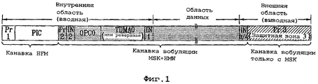
фиг.1 - структура оптического диска, на который можно записывать данные, согласно настоящему изобретению;figure 1 - structure of the optical disk on which you can write data, according to the present invention;
фиг.2 - структура однослойного оптического диска, на который можно записывать данные, согласно настоящему изобретению;figure 2 - structure of a single-layer optical disc on which you can record data, according to the present invention;
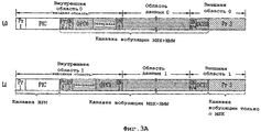
фиг.3А-3В - структуры двухслойного оптического диска, на который можно записывать данные, согласно предпочтительному варианту осуществления настоящего изобретения;3A-3B are structures of a dual layer optical disc onto which data can be recorded, according to a preferred embodiment of the present invention;
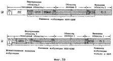
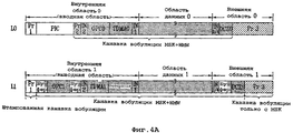
фиг.4А-4В - структуры двухслойного оптического диска, на который можно записывать данные, согласно другому предпочтительному варианту осуществления настоящего изобретения;4A-4B are structures of a two-layer optical disc onto which data can be recorded, according to another preferred embodiment of the present invention;
фиг.5-8 - графики, иллюстрирующие метод модуляции согласно настоящему изобретению;5-8 are graphs illustrating a modulation method according to the present invention;
фиг.9 - принципиальная схема, иллюстрирующая способ записи информации управления на записываемый оптический диск согласно настоящему изобретению;9 is a schematic diagram illustrating a method of recording control information on a recordable optical disc according to the present invention;
фиг.10 - принципиальная схема, иллюстрирующая способ осуществления процесса OPC согласно настоящему изобретению;10 is a schematic diagram illustrating a method for implementing an OPC process according to the present invention;
фиг.11 - принципиальная схема, иллюстрирующая способ поиска начальной позиции OPC согласно настоящему изобретению;11 is a schematic diagram illustrating a method of searching for an OPC starting position according to the present invention;
фиг.12 - блок-схема оптического устройства записи/воспроизведения согласно настоящему изобретению; и12 is a block diagram of an optical recording / reproducing device according to the present invention; and
фиг.13-16 - логические блок-схемы способа записи данных на носитель записи согласно настоящему изобретению.13-16 are logical flowcharts of a method of recording data on a recording medium according to the present invention.
Осуществление изобретенияThe implementation of the invention
Перейдем к подробному рассмотрению предпочтительных вариантов осуществления настоящего изобретения, примеры которых проиллюстрированы на прилагаемых чертежах. По возможности, одни и те же позиции будут использоваться на разных чертежах для обозначения одинаковых или аналогичных объектов.We turn to a detailed discussion of preferred embodiments of the present invention, examples of which are illustrated in the accompanying drawings. If possible, the same positions will be used in different drawings to refer to the same or similar objects.
Прежде чем приступить к описанию настоящего изобретения, следует отметить, что большинство терминов, раскрытых в настоящем изобретении, соответствует общим терминам, хорошо известным в данной области техники, но некоторые термины выбраны заявителем по необходимости и будут далее раскрыты в нижеследующем описании настоящего изобретения. Поэтому, предпочтительно, чтобы термины, определенные заявителем, были поняты на основании их значений в настоящем изобретении.Before proceeding with the description of the present invention, it should be noted that most of the terms disclosed in the present invention correspond to the general terms well known in the art, but some of the terms are selected by the applicant as necessary and will be further described in the following description of the present invention. Therefore, it is preferable that the terms defined by the applicant be understood based on their meanings in the present invention.
Носитель записи для использования в настоящем изобретении подразумевает все записываемые носители, например оптический диск, магнитную ленту и т.д. согласно различным схемам записи. Для удобства описания и лучшего понимания настоящего изобретения оптический диск, например, BD, будет ниже использоваться в иллюстративных целях как вышеупомянутый носитель записи согласно настоящему изобретению.Recording media for use in the present invention includes all recordable media, such as an optical disc, a magnetic tape, etc. according to various recording schemes. For convenience of description and a better understanding of the present invention, an optical disc, for example, BD, will be used below for illustrative purposes as the aforementioned recording medium according to the present invention.
Заметим, что технические идеи настоящего изобретения можно применять к другим носителям записи, не выходя за рамки объема и сущности изобретения. Термин "область оптимального управления мощностью (OPC)" означает заранее определенную область, выделенную для осуществления процесса OPC на носителе записи. Термин "оптимальное управление мощностью (OPC)" означает заранее определенный процесс, позволяющий вычислять оптимальную мощность записи при записи данных (тестирования) на записываемый оптический диск.Note that the technical ideas of the present invention can be applied to other recording media without going beyond the scope and essence of the invention. The term "Optimal Power Management Area (OPC)" means a predetermined area allocated for the implementation of the OPC process on the recording medium. The term “optimal power control (OPC)” means a predetermined process that allows you to calculate the optimal recording power when recording data (testing) on a recordable optical disc.
Иными словами, если оптический диск установлен в конкретном оптическом устройстве записи/воспроизведения, оптическое устройство записи/воспроизведения повторно осуществляет заранее определенный процесс для записи данных в область OPC оптического диска, и воспроизведения записанных данных, что позволяет ему вычислять оптимальную мощность записи, применимую к оптическому диску. Затем оптическое устройство записи/воспроизведения использует вычисленную оптимальную мощность записи при записи данных на оптический диск. Поэтому область OPC необходима для записываемого оптического диска.In other words, if the optical disc is mounted in a particular optical recording / reproducing apparatus, the optical recording / reproducing apparatus repeatedly performs a predetermined process for recording data in the OPC area of the optical disc and reproducing the recorded data, which allows it to calculate the optimum recording power applicable to the optical drive. Then, the optical recording / reproducing apparatus uses the calculated optimum recording power when writing data to the optical disc. Therefore, the OPC area is necessary for a recordable optical disc.
Термин "область зоны калибровки привода (DCZ)" означает конкретную область, используемую оптическим устройством записи/воспроизведения (или приводом) на носителе записи, и позволяет осуществлять не только процесс OPC, но и различные тесты, необходимые для оптического устройства записи/воспроизведения.The term “drive calibration area (DCZ) area” means a specific area used by the optical recording / reproducing device (or drive) on the recording medium, and allows not only the OPC process, but also various tests necessary for the optical recording / reproducing device.
В этом случае, область OPC и область DCZ доступны для процесса OPC. Согласно настоящему изобретению область OPC и область DCZ обычно именуются зонами тестирования. Заметим, что OPC, осуществляющийся в области OPC, применим также к области DCZ.In this case, the OPC area and the DCZ area are available for the OPC process. According to the present invention, the OPC region and the DCZ region are commonly referred to as test zones. Note that the OPC implemented in the OPC area is also applicable to the DCZ area.
На фиг.1 показана структура оптического диска, на который можно записывать данные согласно настоящему изобретению. Для удобства описания и лучшего понимания настоящего изобретения на фиг.1 показан однослойный BD-R/RE, на который можно записывать данные.1 shows the structure of an optical disc on which data according to the present invention can be recorded. For convenience of description and a better understanding of the present invention, FIG. 1 shows a single layer BD-R / RE on which data can be recorded.
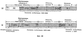
Согласно фиг.1 оптический диск последовательно включает в себя внутреннюю область, область данных и внешнюю область на основании внутренней области диска. Конкретная область, содержащаяся во внутренней области и внешней области, используется либо как область записи для записи информации управления диском, либо как область тестирования. В области данных записываются фактические пользовательские данные. Ниже приведено подробное описание внутренней области и внешней области. Внутренняя область включает в себя область PIC (данных постоянной информации и управления), область OPC, две информационные области IN1 и IN2. В области PIC записывается информация управления диском в виде штампованного HFM (высокочастотно-модулированного) сигнала. Область OPC, выступающая в роли области тестирования, предназначена для осуществления процесса OPC. В информационных областях IN1 и IN2 записывается различная информация управления диском, включая область управления дефектами (DMA).1, an optical disk sequentially includes an inner region, a data region, and an outer region based on the inner region of the disk. The specific region contained in the inner region and the outer region is used either as a recording region for recording disc management information, or as a testing region. Actual user data is recorded in the data area. The following is a detailed description of the inner region and the outer region. The inner area includes a PIC area (permanent information and control data), an OPC area, two information areas IN1 and IN2. In the PIC area, disc management information is recorded in the form of a stamped HFM (high frequency modulated) signal. The OPC area, which acts as the testing area, is designed to implement the OPC process. In the information areas IN1 and IN2, various disc management information is recorded, including a defect management area (DMA).
Согласно вышеприведенному описанию BD-R однократной записи дополнительно включает в себя временную область управления диском (TDMA), примыкающую к области OPC, а BD-RE включает в себя резервную область вблизи области OPC. Резервная область играет роль области восстановления, подлежащей использованию в дальнейшем. Внешняя область включает в себя две другие информационные области IN3 и IN4.According to the above description, the write-once BD-R further includes a temporary disc management area (TDMA) adjacent to the OPC area, and the BD-RE includes a spare area near the OPC area. The backup area plays the role of a recovery area to be used later. The outer area includes two other information areas IN3 and IN4.
Защитные зоны Pr1 и Pr2 для защиты диска входят в состав внутренней области, и защитная зона Pr3 для защиты диска входит в состав внешней области. В частности, защитная область, находящаяся в самой внутренней части внутренней области, именуется первой защитной зоной "Pr1". Защитная область, находящаяся в самой внешней части внешней области, именуется третьей защитной зоной "Pr3". Защитная область, находящаяся между областью PIC и информационной областью IN2 во внутренней области, именуется второй защитной зоной "Pr2". В частности, вторая защитная область "Pr2" указывает переходную область между штампованной областью PIC и записываемой областью и именуется "буферной зоной для перехода".The protection zones Pr1 and Pr2 for protecting the disk are included in the inner region, and the protective zone Pr3 for protecting the disk is included in the outer region. In particular, the protective region located in the innermost part of the inner region is referred to as the first protective zone “Pr1”. The protective region located in the outermost part of the outer region is referred to as the third protective zone “Pr3”. The protection region located between the PIC region and the information region IN2 in the inner region is referred to as the second protection zone “Pr2”. In particular, the second protective region “Pr2” indicates the transition region between the stamped PIC region and the recording region and is referred to as the “transition buffer zone”.
На BD-R/RE согласно настоящему изобретению записываются данные в канавочной части слоя записи, состоящего из площадочной части и канавочной части. Канавочная часть состоит из канавки HFM и канавки вобуляции.On the BD-R / RE according to the present invention, data is recorded in a groove portion of a recording layer consisting of a pad portion and a groove portion. The groove portion consists of an HFM groove and a wobble groove.
Согласно различным схемам модуляции канавка вобуляции подразделяется на канавку модуляции MSK+HMW и канавку модуляции MSK (манипуляции с минимальным сдвигом). MSK - это сокращение от «манипуляция с минимальным сдвигом», а HMW - это сокращение от «модулированной гармонической волны». В частности, канавка вобуляции конфигурируется в виде волнообразной формы с использованием метода модуляции, связанного с синусоидальной волной в канавке, содержащейся в слое записи. Оптическое устройство записи/воспроизведения может считывать информацию адреса (т.е. ADIP: адрес в предварительной канавке) соответствующей канавки и общую информацию диска с использованием вышеупомянутой волнообразной формы. Подробное описание ее будет приведено далее со ссылкой на фиг.5-8.According to various modulation schemes, the wobble groove is subdivided into the MSK + HMW modulation groove and the MSK modulation groove (minimum shift manipulation). MSK is short for “minimal shift manipulation”, and HMW is short for “modulated harmonic wave”. In particular, the wobble groove is configured as a waveform using a modulation method associated with a sine wave in the groove contained in the recording layer. The optical recording / reproducing apparatus can read address information (i.e., ADIP: address in the pre-groove) of the corresponding groove and general disk information using the aforementioned waveform. A detailed description will be given hereinafter with reference to FIGS. 5-8.
Вышеупомянутый метод модуляции по разному применяется к отдельным областям, содержащимся на диске, в соответствии с уникальными характеристиками областей. Область Pr1 и область PIC, содержащиеся во внутренней области, сконфигурированы в виде канавки HFM. Область Pr3, содержащаяся во внешней области, сконфигурирована в виде канавки вобуляции, к которой применяется только модуляция MSK. Кроме вышеупомянутых областей, внутренняя область, внешняя область и область данных сконфигурированы в виде канавки вобуляции, к которой применяется модуляция MSK+HMW.The aforementioned modulation method is applied differently to the individual regions contained on the disc, in accordance with the unique characteristics of the regions. The Pr1 region and the PIC region contained in the inner region are configured as an HFM groove. The Pr3 region contained in the outer region is configured as a wobble groove to which only MSK modulation is applied. In addition to the aforementioned regions, the inner region, the outer region and the data region are configured as a wobble groove to which MSK + HMW modulation is applied.
На фиг.2 показана структура однослойного оптического диска, на который можно записывать данные согласно настоящему изобретению. По сравнению с фиг.1 структура однослойного оптического диска, показанная на фиг.2, дополнительно включает в себя область зоны калибровки привода (DCZ) во внешней области. Нижеследующее описание будет, в основном, приведено относительно области DCZ, а остальные части, отличные от области DCZ, такие же, как на фиг.1, поэтому их подробное описание будет опущено для удобства описания. Согласно вышесказанному область DCZ соответствует зоне тестирования, где оптическое устройство записи/воспроизведения может осуществлять тестирование диска в различных целях. Обычно, процесс OPC осуществляется в области DCZ таким же образом, как в области OPC, играющей роль другой зоны тестирования. Специалистам в данной области техники очевидно, что в области DCZ можно осуществлять не только процесс OPC, но и другое тестирование и нужно заметить, что настоящее изобретение не ограничивается вышеприведенным примером и применимо, при необходимости, к другим случаям.Figure 2 shows the structure of a single-layer optical disc on which data according to the present invention can be recorded. Compared to FIG. 1, the structure of the single-layer optical disc shown in FIG. 2 further includes a region of a drive calibration area (DCZ) in the outer region. The following description will mainly be given with respect to the DCZ region, and other parts other than the DCZ region are the same as in FIG. 1, therefore, a detailed description thereof will be omitted for convenience of description. According to the foregoing, the DCZ region corresponds to the test area, where the optical recording / reproducing device can test the disc for various purposes. Typically, the OPC process is carried out in the DCZ area in the same way as in the OPC area, which plays the role of another test zone. It will be apparent to those skilled in the art that in the DCZ area, not only the OPC process can be performed, but also other testing, and it should be noted that the present invention is not limited to the above example and is applicable, if necessary, to other cases.
По сравнению с фиг.1, область DCZ, показанная на фиг.2, физически включена во внешнюю область. Поэтому область Pr3, показанная на фиг.2, меньше, чем область Pr3, показанная на фиг.1, на заранее определенный размер, соответствующий дополнительно выделенной области DCZ. Предпочтительно, чтобы область DCZ была меньше области OPC (т.е. 2048 кластеров), содержащейся во внутренней области. Например, области DCZ выделено 512 кластеров. Вышеупомянутая дополнительно выделенная область DCZ использует метод модуляции MSK+HMW, в котором модуляция MSK и модуляция HMW смешаны таким же образом, как в области OPC внутренней области и в области данных. Иными словами, вновь выделенная область DCZ предназначена для записи/воспроизведения данных тестирования. Для правильной записи данных тестирования нужно гарантировать надежную информацию адреса (т.е. ADIP) таким же образом, как в общей области данных.Compared to FIG. 1, the DCZ region shown in FIG. 2 is physically included in the outer region. Therefore, the Pr3 region shown in FIG. 2 is smaller than the Pr3 region shown in FIG. 1 by a predetermined size corresponding to the additionally selected DCZ region. Preferably, the DCZ region is smaller than the OPC region (i.e., 2048 clusters) contained in the inner region. For example, in the DCZ area, 512 clusters are allocated. The aforementioned additionally allocated DCZ region uses the MSK + HMW modulation technique in which the MSK modulation and the HMW modulation are mixed in the same manner as in the OPC region of the inner region and in the data region. In other words, the newly allocated DCZ area is for recording / reproducing test data. To correctly record test data, you must ensure reliable address information (i.e., ADIP) in the same way as in the general data area.
На фиг.3А-3В изображены структуры двухслойного оптического диска, на который можно записывать данные согласно предпочтительному варианту осуществления настоящего изобретения. Двухслойный BD-RE показан на фиг.3А. Двухслойный BD-R, на который можно записывать данные, показан на фиг.3В. Согласно вышеприведенному описанию один из двух слоев записи именуется "Layer0 (L0)", а другой именуется "Layer1 (L1)".3A-3B illustrate structures of a two-layer optical disc onto which data can be recorded according to a preferred embodiment of the present invention. A dual layer BD-RE is shown in FIG. 3A. A dual layer BD-R onto which data can be recorded is shown in FIG. 3B. According to the above description, one of the two recording layers is called "Layer0 (L0)" and the other is called "Layer1 (L1)".
Согласно фиг.3А отдельные слои записи имеют одинаковую структуру в двухслойном BD-RE согласно настоящему изобретению. Внешняя область слоя записи L0 включает в себя область DCZ DCZ0, и внешняя область слоя записи L1 включает в себя область DCZ DCZ1. Метод модуляции MSK+HMW, в котором модуляция MSK и модуляция HMW смешаны, применяется к областям DCZ DCZ0 и DCZ1 таким же образом, как в области данных.3A, the individual recording layers have the same structure in a two-layer BD-RE according to the present invention. The outer region of the recording layer L0 includes a DCZ region DCZ0, and the outer region of the recording layer L1 includes a DCZ region DCZ1. The MSK + HMW modulation method, in which the MSK modulation and the HMW modulation are mixed, is applied to the DCZ regions DCZ0 and DCZ1 in the same manner as in the data region.
Согласно фиг.3В двухслойный BD-R однократной записи согласно настоящему изобретению включает в себя области DCZ во внешних областях отдельных слоев записи L0 и L1. Области DCZ DCZ0 и DCZ1 используют метод модуляции MSK_HMW, в котором модуляция MSK и модуляция HMW смешаны таким же образом, как в области данных.Referring to FIG. 3B, a two-layer write-once BD-R according to the present invention includes DCZ regions in the outer regions of the individual recording layers L0 and L1. DCZ regions DCZ0 and DCZ1 use the MSK_HMW modulation method, in which the MSK modulation and the HMW modulation are mixed in the same way as in the data region.
По сравнению с BD-RE, показанным на фиг.3А, BD-R однократной записи, показанный на фиг.3В, требует гораздо больше областей записи информации управления вследствие особенностей однократной записи, поэтому временная область управления диском (TDMA) добавляется к внутренней области, и внутренняя область второго слоя записи L1 включает в себя область OPC (OPC1) вместо области PIC, штампованной посредством HFM.Compared to the BD-RE shown in FIG. 3A, the write-once BD-R shown in FIG. 3B requires much more recording areas of control information due to the features of write-once, therefore, a temporary disc management area (TDMA) is added to the inner area, and the inner region of the second recording layer L1 includes an OPC region (OPC1) instead of a PIC region stamped by HFM.
Согласно вышеприведенному описанию область DCZ настоящего изобретения более эффективно доступна для BD-R однократной записи, показанного на фиг.3В. В частности, BD-R однократной записи требует гораздо больше слоев записи информации управления вследствие особенностей однократной записи, как указано выше, поэтому он использует область DCZ как новую область тестирования, способную заменять область OPC внутренней области, и устраняет проблему, заключающуюся в том, что данные больше не записываются на BD-R однократной записи вследствие недостаточного размера области OPC.As described above, the DCZ region of the present invention is more efficiently available for the write-once BD-R shown in FIG. 3B. In particular, the write-once BD-R requires a lot more management information recording layers due to the write-once features, as mentioned above, therefore, it uses the DCZ area as a new testing area, able to replace the OPC area of the internal area, and eliminates the problem that data is no longer written to the write-once BD-R due to insufficient OPC area.
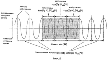
На фиг.4А-4В показаны структуры двухслойного оптического диска, на который можно записывать данные, согласно другому предпочтительному варианту осуществления настоящего изобретения. Способ выделения области DCZ в отдельных слоях записи показан на фиг.4А-4В.4A-4B show structures of a dual layer optical disc onto which data can be recorded, according to another preferred embodiment of the present invention. A method for isolating the DCZ region in separate recording layers is shown in FIGS. 4A-4B.
Согласно вышеприведенному описанию, хотя на фиг.4А-4В показан для иллюстрации записываемый диск однократной записи (например, BD-R) для удобства описания, технические идеи настоящего изобретения применимы к перезаписываемому диску (например, BD-RE), описанному выше. Согласно фиг.4А при выделении областей DCZ DCZ0 и DCZ1 отдельным внешним областям отдельных слоев записи, области DCZ DCZ0 и DCZ1 физически не находятся в одной и той же позиции относительно направления распространения оптического пучка.According to the above description, although FIGS. 4A-4B are shown to illustrate a recordable write-once disc (e.g., BD-R) for ease of description, the technical ideas of the present invention apply to a rewritable disc (e.g., BD-RE) described above. 4A, when the DCZ regions DCZ0 and DCZ1 are selected to separate external regions of the individual recording layers, the DCZ regions DCZ0 and DCZ1 are not physically in the same position relative to the direction of propagation of the optical beam.
Иными словами, при условии, что области DCZ используются для процесса OPC таким же образом, как в области OPC внутренней области, для процесса OPC используется заранее определенное значение мощности постепенно в направлении от высокой мощности к низкой мощности или в направлении от низкой мощности к высокой мощности, или для процесса OPC используется значение мощности, содержащееся в заранее определенном диапазоне относительно опорной мощности.In other words, provided that DCZ regions are used for the OPC process in the same way as in the OPC region of the inner region, a predetermined power value is used for the OPC process gradually in the direction from high power to low power or in the direction from low power to high power or, for the OPC process, a power value is used that is contained in a predetermined range relative to the reference power.
При условии, что области DCZ DCZ0 и DCZ1 физически находятся в одной и той же позиции относительно направления распространения оптического пучка между слоями записи, примыкающими друг к другу, вероятность генерации интерференции пучков света даже в области DCZ (например, DCZ1), содержащейся в соседнем слое записи, отличной от фактически используемой области DCZ (например, DCZ0), увеличивается, что негативно влияет на процесс вычисления оптической мощности записи с использованием процесса OPC. Таким образом, области OPC OPC0 и OPC1, содержащиеся во внутренних областях, физически не находятся в одной той же позиции относительно направления распространения оптического пучка.Provided that the DCZ regions DCZ0 and DCZ1 are physically in the same position relative to the direction of propagation of the optical beam between the recording layers adjacent to each other, the probability of generation of interference of light beams even in the DCZ region (for example, DCZ1) contained in the adjacent layer a recording other than the actual used DCZ area (e.g., DCZ0) is increased, which negatively affects the process of calculating the optical recording power using the OPC process. Thus, the OPC regions OPC0 and OPC1 contained in the inner regions are not physically in the same position relative to the propagation direction of the optical beam.
Поэтому, внешняя область второго слоя записи дополнительно включает в себя буферную область, находящуюся в той же позиции, что и область DCZ (DCZ0) первого слоя записи относительно направления распространения оптического пучка, и область DCZ (DCZ1) затем выделяется во внешнем направлении. Очевидно, что отдельные способы выделения внешней области для первого слоя записи L0 и второго слоя записи L1 можно осуществлять в любом порядке. Например, буферную область можно добавить к внешней области первого слоя записи L1 в той же позиции, что и в области DCZ (DCZ1) второго слоя записи L1 относительно направления распространения света или оптического пучка, и область DCZ (DCZ0) также можно разместить во внешнем направлении.Therefore, the outer region of the second recording layer further includes a buffer region at the same position as the DCZ region (DCZ0) of the first recording layer with respect to the propagation direction of the optical beam, and the DCZ region (DCZ1) is then allocated in the outer direction. Obviously, separate methods for allocating an external area for the first recording layer L0 and the second recording layer L1 can be performed in any order. For example, the buffer region can be added to the outer region of the first recording layer L1 at the same position as in the DCZ (DCZ1) region of the second recording layer L1 with respect to the direction of light or optical beam propagation, and the DCZ region (DCZ0) can also be placed in the outer direction .
Согласно вышеприведенному описанию области DCZ (DCZ0 и DCZ1) используют метод модуляции MZK+HMW, в котором модуляция MSK и модуляция HMW смешаны таким же образом, как в области данных.According to the above description of the DCZ region (DCZ0 and DCZ1), the MZK + HMW modulation method is used, in which the MSK modulation and HMW modulation are mixed in the same way as in the data region.
Согласно фиг.4В область DCZ отличается тем, что она выделена не только внешним областям отдельных слоев записи, но и соседней области данных. Иными словами, слой записи подразделяется на слой записи первого типа (например, L1) и слой записи второго типа (например, L0). Область DCZ (DCZ1) содержится во внешней области слоя записи первого типа, область DCZ (DCZ0) содержится в области данных, примыкающей ко внешней области в слое записи второго типа, и слой записи первого типа и слой записи второго типа попеременно включены в оптический диск.4B, the DCZ region is characterized in that it is allocated not only to the outer regions of the individual recording layers, but also to the neighboring data region. In other words, the recording layer is divided into a recording layer of the first type (e.g., L1) and a recording layer of the second type (e.g., L0). The DCZ region (DCZ1) is contained in the outer region of the first type recording layer, the DCZ region (DCZ0) is contained in the data region adjacent to the outer region in the second type recording layer, and the first type recording layer and the second type recording layer are alternately included in the optical disc.
На фиг.5-8 показаны графики, иллюстрирующие метод модуляции согласно настоящему изобретению.5-8 are graphs illustrating a modulation method according to the present invention.
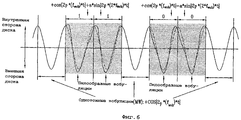
На фиг.5 показан метод модуляции MSK. В частности, область Pr3 (т.е. защитная зона 3), содержащаяся во внешней области, сформирована только посредством модуляции MSK.5 shows an MSK modulation technique. In particular, the Pr3 region (i.e., protection zone 3) contained in the outer region is formed only by modulation of the MSK.
Метод модуляции MSK реализуется путем осуществления косинусного преобразования на частоте вобуляции fwob, как показано на фиг.5. Общая вобуляция именуется "однотонной вобуляцией (MW)", и три вобуляции, генерируемые путем изменения частоты вобуляции fwob и косинусного кода, именуются "вобуляцией метки MSK (MM)".The MSK modulation method is implemented by performing cosine transform at the wobble frequency f wob , as shown in FIG. Common wobble is referred to as “monophonic wobble (MW)”, and the three wobbles generated by changing the wobble frequency f wob and the cosine code are referred to as “MSK mark wobble (MM)”.
На фиг.6 показан метод модуляции HMW. В частности, область OPC, содержащаяся во внутренней области, и область DCZ и область данных, содержащиеся во внешней области, сформированы посредством метода модуляции MSK+HMW, в котором модуляция HMW и модуляция MSK смешаны.6 shows an HMW modulation technique. In particular, the OPC region contained in the inner region, and the DCZ region and the data region contained in the outer region are formed by an MSK + HMW modulation method in which HMW modulation and MSK modulation are mixed.
Согласно вышеприведенному описанию, как показано на фиг.6, метод модуляции HMW реализуется посредством косинусного преобразования, осуществляемого на первой частоте вобуляции fwob, и синусного преобразования, осуществляемого на второй частоте вобуляции 2*fwob. Если синусное преобразование имеет положительный (+) код, определяется значение 1. Если синусное преобразование имеет отрицательный (-) код, определяется значение 0. Вобуляция, сформированная вышеупомянутым методом, именуется "пилообразной вобуляцией (STW)". Пилообразная вобуляция (STW) со значением 1 именуется STW("1"). Пилообразная вобуляция (STW) со значением 0 именуется STW("0").According to the above description, as shown in FIG. 6, the HMW modulation method is implemented by a cosine transform performed on a first wobble frequency f wob and a sine transform performed on a
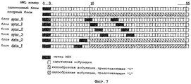
На фиг.7 показан способ идентификации блока ADIP с использованием метода модуляции MSK+HMW. Согласно фиг.7 один блок ADIP включает в себя 56 вобуляций. Три головные вобуляции каждого блока ADIP состоят из метки MSK (MM). Блоки ADIP подразделяются на следующие блоки согласно типам вобуляции.7 shows a method for identifying an ADIP block using the MSK + HMW modulation method. 7, one ADIP unit includes 56 wobbles. The three head wobbles of each ADIP block consist of an MSK tag (MM). ADIP blocks are divided into the following blocks according to the type of wobble.
Иными словами, блок ADIP, состоящий из "1 MM + 53 MW", именуется однотонным блоком, и блок ADIP, состоящий из "1 MM + 15MW + 37 STW("0") + 1MW", именуется опорным блоком.In other words, an ADIP block consisting of “1 MM + 53 MW” is referred to as a monophonic block, and an ADIP block consisting of “1 MM + 15MW + 37 STW (“ 0 ”) + 1MW” is referred to as a reference block.
Блок ADIP, состоящий из "1 MM + 13 MW + 1 MM + 7 MW + 1 MM + 27 MW", именуется "блоком sync_0". Блок ADIP, состоящий из "1 MM + 15 MW + 1 MM + 7 MW + 1 MM + 25 MW", именуется “блоком sync_1". Блок ADIP, состоящий из "1 MM + 17 MW + 1 MM + 7 MW + 1 MM + 23 MW", именуется "блоком sync_2". Блок ADIP, состоящий из "1 MM + 19 MW + 1 MM + 7 MW + 1 MM + 21 MW", именуется "блоком sync_3". Блок ADIP, состоящий из "1 MM + 9 MW + 1 MM + 3 MW + 37 STW("0"), именуется "блоком data_1". Блок ADIP, состоящий из "1 MM + 11 MW + 1 MM + 1 MW + 37 STW("1") + 1 MW", именуется "блоком data_0". Иными словами, если определен "блок data_1", устанавливается значение 1. Если определен "блок data_0", устанавливается значение 0.An ADIP block consisting of "1 MM + 13 MW + 1 MM + 7 MW + 1 MM + 27 MW" is referred to as a "sync_0 block". An ADIP block consisting of "1 MM + 15 MW + 1 MM + 7 MW + 1 MM + 25 MW" is referred to as a "sync_1 block." An ADIP block consisting of "1 MM + 17 MW + 1 MM + 7 MW + 1 MM + 23 MW ", referred to as a" sync_2 block. "An ADIP block consisting of" 1 MM + 19 MW + 1 MM + 7 MW + 1 MM + 21 MW "is referred to as a" sync_3 block. "An ADIP block consisting of" 1 MM + 9 MW + 1 MM + 3 MW + 37 STW ("0"), referred to as the "data_1 block". An ADIP block consisting of "1 MM + 11 MW + 1 MM + 1 MW + 37 STW (" 1 ") + 1 MW" is referred to as a "data_0 block". In other words, if the "data_1 block" is defined, the value is 1. If the "data_0 block" is defined, the
На фиг.8 показан способ построения одного слова ADIP, состоящего из 83 блоков ADIP, показанных на фиг.7.On Fig shows a method of constructing a single word ADIP, consisting of 83 ADIP blocks shown in Fig.7.
Согласно фиг.8, 9 головных блоков ADIP слова ADIP последовательно включают в себя "однотонный блок", "sync_0 unit", "однотонный блок", "блок sync_1", "однотонный блок", "блок sync_2", "однотонный блок", "блок sync_3" и "опорный блок". Каждый из блоков ADIP с 10-го блока ADIP (т.е. номер блока ADIP = 9) по 83-й блок ADIP (т.е. номер блока ADIP = 82) состоит из "блока data_0" либо "блока data_1", показанных на фиг.7. Пять блоков формируются путем объединения блоков ADIP с помощью четырех битов, поэтому вышеупомянутые блоки именуются "номерами полубайтов кодового слова ADIP (c0-c14)".According to Fig. 8, 9 ADIP headunits, the ADIP words sequentially include "plain block", "sync_0 unit", "plain block", "sync_1 block", "plain block", "sync_2 block", "plain block", "sync_3 block" and "reference block". Each ADIP block from the 10th ADIP block (i.e., the ADIP block number = 9) through the 83rd ADIP block (i.e. the ADIP block number = 82) consists of a “data_0 block” or a “data_1 block”, shown in Fig.7. Five blocks are formed by combining ADIP blocks with four bits, so the above blocks are called "ADIP codeword half-byte numbers (c0-c14)."
Физический адрес (т.е. физический адрес ADIP "PAA") соответствующей вобуляции и вспомогательные данные записываются в вышеупомянутый номер полубайта кодового слова ADIP (c0-c14). Оптическое устройство записи/воспроизведения считывает одно слово ADIP, что позволяет ему выявить позицию PAA данного диска.The physical address (ie, the physical ADIP address "PAA") of the corresponding wobble and auxiliary data is recorded in the aforementioned nibble number of the ADIP codeword (c0-c14). The optical recorder / player reads one ADIP word, which allows it to identify the PAA position of a given disc.
Технические идеи, показанные на фиг.5-8, применяются ко всем областям, к которым применяется метод модуляции MSK+HMW. Поэтому, метод модуляции MSK+HMW применяется даже к области DCZ, содержащейся во внешней области.The technical ideas shown in FIGS. 5-8 apply to all areas to which the MSK + HMW modulation method is applied. Therefore, the MSK + HMW modulation method is applied even to the DCZ region contained in the external region.
Причина, по которой метод модуляции MSK+HMW применяется к области DCZ, такова. Область DCZ соответствует конкретной области для записи фактических данных тестирования. Поэтому, если только метод модуляции MSK применяется к области DCZ таким же образом, как в области Pr3 (т.е. защитной зоне 3), пилообразная вобуляция (STW), обусловленная модуляцией HMW, не используется, поэтому "однотонный блок" и "опорный блок" из блоков ADIP, показанных на фиг.7, невозможно отличить друг от друга, и при различении "блока data_1" и “блока data_0" может возникнуть непредсказуемая ошибка.The reason the MSK + HMW modulation method is applied to the DCZ domain is this. The DCZ area corresponds to a specific area for recording actual test data. Therefore, if only the MSK modulation method is applied to the DCZ region in the same way as in the Pr3 region (i.e., protection zone 3), sawtooth wobble (STW) due to HMW modulation is not used, therefore the “solid block” and “reference block” block "from the ADIP blocks shown in Fig.7, it is impossible to distinguish from each other, and when you distinguish between" block data_1 "and" block data_0 "an unpredictable error may occur.
Предпочтительно, область DCZ может использовать метод модуляции MSK+HMW для предотвращения возникновения непредсказуемой ошибки, в отличие от области Pr3 (т.е. защитной зоны 3), к которой применяется только метод модуляции MSK.Preferably, the DCZ region can use the MSK + HMW modulation method to prevent an unpredictable error from occurring, unlike the Pr3 region (i.e., protection zone 3), to which only the MSK modulation method is applied.
Настоящее изобретение применимо к носителю записи, в котором обеспечена совокупность слоев, играющих роль слоев записи.The present invention is applicable to a recording medium in which a plurality of layers acting as recording layers is provided.
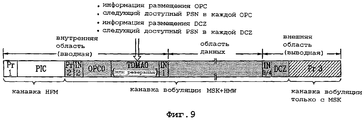
На фиг.9 показана принципиальная схема способа записи информации управления, предназначенной для управления областью OPC и областью DCZ на оптическом диске.Figure 9 shows a schematic diagram of a method for recording management information for controlling an OPC area and a DCZ area on an optical disc.
В частности, DMA (область управления диском) и/или TDMA (временная DMA) включены во внутреннюю область и/или внешнюю область оптического диска. Информация управления области OPC и области DCZ записывается в TDMA или DMA. Иными словами, информация управления записывается в TDMA в случае записываемого диска однократной записи, например, BD-R, и информация управления записывается в DMA в случае перезаписываемого диска, например, BD-RE. Согласно фиг.1 DMA обычно входит в состав информационных областей IN1 и IN2 внутренней области или других информационных областей IN3 и IN4 внешней области.In particular, DMA (disc management area) and / or TDMA (temporary DMA) are included in the inner region and / or outer region of the optical disc. The management information of the OPC area and the DCZ area is recorded in TDMA or DMA. In other words, control information is recorded in TDMA in the case of a recordable write-once disc, for example, BD-R, and control information is recorded in DMA in the case of a rewritable disc, for example, BD-RE. According to figure 1, the DMA is usually included in the information areas IN1 and IN2 of the internal area or other information areas IN3 and IN4 of the external area.
Согласно вышеприведенному описанию информация управления области OPC и области DCZ может включать в себя информацию, указывающую позиции области OPC и области DCZ для каждого слоя записи диска, например, информацию начального адреса и/или информацию конечного адреса (т.е. "информацию размещения OPC" и "информацию размещения DCZ") и информацию, указывающую доступные на данный момент позиции в отдельной OPC и областях DCZ (т.е. "следующий доступный PSN в каждой OPC" и "следующий доступный PSN в каждой DCZ").According to the above description, the control information of the OPC area and the DCZ area may include information indicating the positions of the OPC area and the DCZ area for each disc recording layer, for example, start address information and / or end address information (ie, “OPC placement information” and “DCZ allocation information”) and information indicating the currently available positions in the individual OPC and DCZ areas (ie, “next available PSN in each OPC” and “next available PSN in each DCZ”).
Поэтому, если диск установлен в оптическом устройстве записи/воспроизведения, оптическое устройство записи/воспроизведения считывает информацию управления области OPC и области DCZ, содержащихся в TDMA или DMA. Поэтому, оптическое устройство записи/воспроизведения выявляет информацию позиции области OPC, содержащейся на диске, и другую информацию позиции доступной области OPC, и выявляет информацию позиции области DCZ и другую информацию позиции доступной области DCZ, что позволяет ему осуществлять процесс OPC в выявленных позициях.Therefore, if the disc is installed in the optical recording / reproducing apparatus, the optical recording / reproducing apparatus reads the control information of the OPC region and the DCZ region contained in the TDMA or DMA. Therefore, the optical recording / reproducing device detects the position information of the OPC area contained on the disc and other position information of the available OPC area, and identifies the position information of the DCZ area and other position information of the available DCZ area, which allows it to carry out the OPC process at the detected positions.
Специалистам в данной области техники очевидно, что информация управления, связанная с областью OPC и областью DCZ, в равной степени применима ко всем оптическим дискам, показанным на фиг.2-4В.Those skilled in the art will appreciate that the management information associated with the OPC area and the DCZ area is equally applicable to all of the optical disks shown in FIGS. 2-4B.
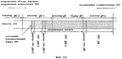
На фиг.10 показана принципиальная схема способа осуществления процесса OPC согласно настоящему изобретению. Направление обхода дорожки носителя записи в оптическом устройстве записи/воспроизведения на носителе записи определяется как направление увеличения PSN, в котором PSN возрастает в направлении от низкого PSN (номера физического сектора) к высокому PSN. Направление для осуществления процесса OPC на носителе записи определяется как направление уменьшения PSN, в котором PSN уменьшается в направлении от высокого PSN к низкому PSN.10 is a schematic diagram of a method for implementing an OPC process according to the present invention. The path direction of the track of the recording medium in the optical recording / reproducing device on the recording medium is defined as the direction of increase of the PSN, in which the PSN increases in the direction from the low PSN (physical sector number) to the high PSN. The direction for the OPC process on the recording medium is defined as the direction of decrease of the PSN, in which the PSN decreases in the direction from high PSN to low PSN.
Направление записи после процесса OPC определяется как направление увеличения PSN от низкого PSN к высокому PSN таким же образом, как направление обхода дорожки.The recording direction after the OPC process is defined as the direction of increasing the PSN from low PSN to high PSN in the same way as the direction of the track.
Согласно вышеприведенному описанию блок для записи данных путем осуществления процесса OPC в области OPC может точно соответствовать 1-кластерному блоку, тогда как блоком для записи данных в области данных носителя записи является 1-кластерный блок. Однако область записи данных, полученная с помощью процесса OPC, может составлять менее 1 кластера, а может быть больше 1 кластера.According to the above description, a unit for recording data by performing an OPC process in an OPC area can exactly correspond to a 1-cluster unit, while a unit for recording data in a data area of a recording medium is a 1-cluster unit. However, the data recording area obtained using the OPC process may be less than 1 cluster, or may be more than 1 cluster.
Иными словами, блок данных, записываемых для осуществления процесса OPC, равен номеру блока адреса (AUN). AUN указывает информацию адреса, используемую во время записи данных. Специалистам в данной области техники очевидно, что неиспользованная область OPC, играющая роль предыдущей области, сформированной до записи данных, не включает в себя вышеупомянутую информацию AUN.In other words, the block of data recorded for the OPC process is equal to the address block number (AUN). AUN indicates the address information used during data recording. It will be apparent to those skilled in the art that the unused OPC area, playing the role of the previous area formed prior to data recording, does not include the above AUN information.
В этом случае, AUN играет роль блока, имеющего диапазон менее кластера, и один кластер включает в себя 16 AUN. В частности, длина осуществления одного процесса OPC выбирается оптическим устройством записи/воспроизведения и не ограничивается количеством физических кластеров.In this case, the AUN plays the role of a block having a range of less than a cluster, and one cluster includes 16 AUNs. In particular, the implementation length of one OPC process is selected by the optical recording / reproducing device and is not limited by the number of physical clusters.
На фиг.10 показан частный случай осуществления трех процессов OPC. В частности, на фиг.10 показана совокупность участков, в каждом из которых осуществляется процесс OPC, и совокупность маркеров OPC для идентификации отдельных участков. Участок для осуществления первого процесса OPC обозначается как "кластер #P+1" и включает в себя первый участок, обозначаемый как "OPC #M", и второй участок, обозначаемый как "маркер OPC #M". В части "OPC #M" записываются данные, и участок "маркер OPC #M" идентифицирует участок "OPC #M".Figure 10 shows a special case of the implementation of three OPC processes. In particular, FIG. 10 shows a plurality of plots in each of which an OPC process is performed, and a plurality of OPC markers for identifying individual plots. The site for the first OPC process is referred to as “cluster # P + 1” and includes a first site designated as “OPC #M” and a second site designated as “OPC #M marker”. In the "OPC #M" portion, data is recorded, and the "OPC #M marker" portion identifies the "OPC #M" portion.
Участок для осуществления второго процесса OPC включает в себя "кластер #P", "кластер #N" и некоторые участки "кластер #N-1". В участке, обозначаемом "OPC #M+1", записываются данные, и "маркер OPC #M+1" идентифицирует участок "OPC #M+1".The site for the second OPC process includes a "cluster #P", "cluster #N" and some sections "cluster # N-1". In the area designated "OPC # M + 1", data is recorded, and the "OPC # M + 1 marker" identifies the area "OPC # M + 1".
Участок для осуществления третьего процесса OPC состоит из нескольких участков участка "кластер #N-1". В частности, участок для осуществления третьего процесса OPC включает в себя "OPC #M+2" и "маркер OPC #M+2". В участке "OPC #M+2" записываются данные, и участок "маркер OPC #M+2" идентифицирует участок "OPC #M+2". В этом случае, "кластер #N-2" и некоторые участки участка "кластер #N-1", расположенные до участка "маркер OPC #M+2", выступают в роли неиспользованных областей кластера.The site for the third OPC process consists of several sites of the cluster # N-1 site. In particular, the site for implementing the third OPC process includes “OPC # M + 2” and “OPC # M + 2 marker”. In the "OPC # M + 2" section, data is recorded, and the "OPC # M + 2 marker" section identifies the "OPC # M + 2" section. In this case, “cluster # N-2” and some sections of the cluster # N-1 section located before the OPC marker # M + 2 section act as unused areas of the cluster.
Согласно вышеприведенному описанию расстояние между двумя последовательными маркерами OPC из маркеров OPC, способных идентифицировать области записи данных, связанные с процессом OPC, меньше или равно заранее определенному расстоянию, соответствующему 16 кластерам. Например, для выполнения вышеупомянутых требований в процессе OPC, требующем, по меньшей мере, 16 кластеров, маркер OPC нужно вставить в процесс OPC. В этом случае, вышеупомянутый маркер OPC должен иметь заранее определенную длину, соответствующую, по меньшей мере, 868 NWL (номинальных длин вобуляции).According to the above description, the distance between two consecutive OPC markers from OPC markers capable of identifying data recording areas associated with the OPC process is less than or equal to a predetermined distance corresponding to 16 clusters. For example, to fulfill the above requirements in an OPC process that requires at least 16 clusters, an OPC token must be inserted into the OPC process. In this case, the aforementioned OPC marker must have a predetermined length corresponding to at least 868 NWL (nominal wobble lengths).
Часть "OPC #M", показанная на фиг.10, занимает один кластер (т.е. 1 кластер) в области OPC. Участок "OPC #M+1" занимает заранее определенную область, большую 1 кластера, в области OPC. Участок "OPC #M+2" занимает заранее определенную область, меньшую 1 кластера, в области OPC. Можно понять, что процесс OPC осуществляется в блоке, меньшем блока кластера, например, в блоке AUN.The “OPC #M” part shown in FIG. 10 occupies one cluster (i.e., 1 cluster) in the OPC area. The "OPC # M + 1" section occupies a predetermined area larger than 1 cluster in the OPC area. The OPC # M + 2 section occupies a predetermined area less than 1 cluster in the OPC area. You can understand that the OPC process is carried out in a block smaller than the cluster block, for example, in the AUN block.
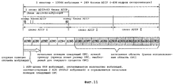
На фиг.11 показана принципиальная схема способа поиска начальной позиции OPC согласно настоящему изобретению.11 is a schematic diagram of a method for searching for an OPC starting position according to the present invention.
На фиг.11 показан 1 кластер из области OPC. 1 кластер соответствует 13944 вобуляциям, 249 блокам ADIP, 498 кадрам синхронизации и 3 словам ADIP. Согласно вышеприведенному описанию 1 слово ADIP включает в себя 83 блока ADIP, и блок ADIP включает в себя 56 вобуляций. 1 кластер включает в себя 16 AUN. В этом случае, вобуляция соответствует NWL (номинальной длине вобуляции).11
Например, ранее использованная (т.е., последняя использованная) область OPC (т.е. AUN6~AUN15), содержащаяся в 1 кластере, указывает 10 AUN (номеров блока адреса), и неиспользованная область OPC указывает 6 AUN с AUN0 по AUN5. AUN6 в последней использованной области OPC можно определить вставлением маркера OPC перед AUN6, как показано на фиг.10. Рабочий размер OPC, соответствующий заранее определенному размеру, необходимому для текущего процесса OPC, заранее определяется оптическим устройством записи/воспроизведения и может задаваться разными способами. Предполагается, что рабочий размер OPC равен 4 AUN с AUN2 по AUN5.For example, a previously used (i.e., last used) OPC area (i.e. AUN6 ~ AUN15) contained in 1 cluster indicates 10 AUN (address block numbers), and an unused OPC area indicates 6 AUN from AUN0 to AUN5 . AUN6 in the last used OPC area can be determined by inserting an OPC marker before AUN6, as shown in FIG. 10. The OPC working size corresponding to a predetermined size required for the current OPC process is predetermined by the optical recording / reproducing device and can be set in various ways. It is assumed that the working size of the OPC is 4 AUN from AUN2 to AUN5.
Поэтому, если пользователь желает осуществить новый процесс OPC с заранее определенной позиции AUN2, пользователь должен искать физическую позицию, соответствующую AUN2. Поэтому, для определения начальной позиции OPC с использованием процесса отсчета вобуляций, необходимо найти опорную позицию счетчика вобуляций. Если заранее определенная опорная вобуляция обнаружена в процессе обнаружения, осуществляемом оптическим устройством записи/воспроизведения, обнаруженная опорная вобуляция считается опорной позицией счетчика вобуляций. Предпочтительно, чтобы опорная позиция счетчика вобуляций была равна начальной позиции кластера.Therefore, if the user wants to implement a new OPC process from a predetermined position AUN2, the user must look for a physical position corresponding to AUN2. Therefore, to determine the starting position of the OPC using the wobble counting process, it is necessary to find the reference position of the wobble counter. If a predetermined reference wobble is detected in the detection process by the optical recording / reproducing device, the detected reference wobble is considered to be the reference position of the wobble meter. Preferably, the reference position of the wobble counter is equal to the initial position of the cluster.
Вышеупомянутая начальная позиция кластера, соответствующая опорной позиции счетчика вобуляций, идентична начальной позиции слова ADIP. Согласно фиг.7-8, 9 головных блоков ADIP слова ADIP соответствуют последовательности: "однотонный блок", "блок sync_0", "однотонный блок", "блок sync_1", "однотонный блок", "блок sync_2", "однотонный блок", "блок sync_3" и "опорный блок". Поэтому, если последовательно обнаруживаются 9 головных блоков ADIP слова ADIP или обнаруживается первый "однотонный блок" в течение времени поиска оптического устройства записи/воспроизведения, устанавливается начальная позиция слова ADIP. Иными словами, начальная позиция кластера считается опорной позицией счетчика вобуляций.The aforementioned starting position of the cluster corresponding to the reference position of the wobble counter is identical to the starting position of the word ADIP. 7-8, 9 ADIP headunits ADIP words correspond to the sequence: "plain block", "sync_0 block", "plain block", "sync_1 block", "plain block", "sync_2 block", "plain block" , "sync_3 block" and "reference block". Therefore, if 9 ADIP headunits of the ADIP word are sequentially detected or the first “plain block” is detected during the search time of the optical recording / reproducing device, the initial position of the ADIP word is set. In other words, the initial position of the cluster is considered to be the reference position of the wobble counter.
Согласно другому примеру вышеупомянутой опорной позиции предпочтительно рассматривать начальную позицию слова ADIP, содержащуюся в 1 кластере, как опорную позицию счетчика вобуляций.According to another example of the aforementioned reference position, it is preferable to consider the initial position of the word ADIP contained in 1 cluster as the reference position of the wobble counter.
Иными словами, 1 кластер включает в себя три слова ADIP. В этом случае, если начальная позиция следующей OPC находится в области "ADIP Word 1" или в области "ADIP Word 2", 9 головных блоков ADIP слова ADIP, указывающие начальную позицию области "ADIP Word 2", соответствуют последовательности: "однотонный блок", "блок sync_0", "однотонный блок", "блок sync_1", "однотонный блок", "блок sync_1", "однотонный блок", "блок sync_2", "однотонный блок", "блок sync_3" и "опорный блок". Если же обнаружен первый "однотонный блок", начальная позиция области "ADIP Word 1" или начальная позиция области "ADIP Word 2" определяется как опорная позиция счетчика вобуляций, что позволяет подсчитать количество вобуляций.In other words, 1 cluster includes three ADIP words. In this case, if the starting position of the next OPC is in the "
Поэтому, если опорная позиция счетчика вобуляций определена и информация размера ранее использованной области OPC, играющей роль записанной области, и информация размера области OPC, необходимого для текущего процесса OPC, выявлены, оптическое устройство записи/воспроизведения подсчитывает количество вобуляций в опорной позиции счетчика вобуляций и ищет начальную позицию OPC, нужную приводу.Therefore, if the reference position of the wobble meter is determined, and the size information of the previously used OPC area playing the role of the recorded area, and the size information of the OPC area needed for the current OPC process are detected, the optical recording / reproducing device counts the number of wobbles in the reference position of the wobble meter and searches The starting position of the OPC needed by the drive.
Согласно предпочтительному варианту осуществления, показанному на фиг.11, привод подсчитывает вобуляции двух AUN с AUN0 по AUN1. Один AUN соответствует длине 868 вобуляций. Поэтому, два AUN соответствуют длине 868·2 вобуляций, привод отсчитывает вобуляции в количестве 868·2 для определения начальной позиции OPC и осуществляет процесс OPC для вычисления оптимальной мощности записи в определенной начальной позиции OPC.According to the preferred embodiment shown in FIG. 11, the drive counts the wobbles of two AUNs from AUN0 to AUN1. One AUN corresponds to the length of 868 wobbles. Therefore, two AUNs correspond to a length of 868 · 2 wobbles, the drive counts the wobbles in the amount of 868 · 2 to determine the starting position of the OPC and performs an OPC process to calculate the optimal recording power at a specific starting position of the OPC.
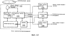
На фиг.12 показана блок-схема оптического устройства записи/воспроизведения согласно настоящему изобретению.12 is a block diagram of an optical recording / reproducing apparatus according to the present invention.
Согласно фиг.12 оптическое устройство записи/воспроизведения включает в себя блок 20 записи/воспроизведения для записи/воспроизведения данных на/с оптического диска и контроллер 12 для управления блоком 20 записи/воспроизведения.12, the optical recording / reproducing apparatus includes a recording / reproducing unit 20 for recording / reproducing data on / from the optical disc and a
Блок 20 записи/воспроизведения включает в себя блок 11 оптической головки, процессор сигналов 13, блок 14 сервопривода, память 15 и микропроцессор 16. Блок 11 оптической головки непосредственно записывает данные на оптический диск или считывает данные, записанные на оптическом диске. Процессор сигналов 13 принимает сигнал, считанный с блока 11 оптической головки, восстанавливает из принятого сигнала полезный сигнал или модулирует сигнал, подлежащий записи, в другой сигнал, записываемый на оптический диск, что позволяет ему передавать восстановленный или модулированный результат. Блок 14 сервопривода управляет работой блока 11 оптической головки, чтобы он правильно считывал полезный сигнал с оптического диска и правильно записывал сигнал на оптический диск. В памяти 15 временно хранится не только информация управления, включающая в себя данные PIC, но и данные. Микропроцессор 16 управляет всеми операциями вышеупомянутых компонентов. Вышеупомянутый блок 20 записи/воспроизведения осуществляет заранее определенный тест в области тестирования носителя записи, что позволяет ему вычислить оптимальную мощность записи. Блок 20 записи/воспроизведения записывает вычисленную оптимальную мощность записи и записывает данные на носитель записи с вычисленной оптимальной мощностью записи после приема команды записи от контроллера 12.The recording / reproducing unit 20 includes an
Блок 20 записи/воспроизведения определяет, форматирован ли оптический диск, играющий роль носителя записи, в процессе инициализации. Если оптический диск не форматирован, блок 20 записи/воспроизведения осуществляет форматирование оптического диска.The recording / reproducing unit 20 determines whether an optical disk playing the role of a recording medium is formatted during the initialization process. If the optical disc is not formatted, the recording / reproducing unit 20 formats the optical disc.
Согласно вышеприведенному описанию оптическое устройство записи/воспроизведения, состоящее только из блока 10 записи/воспроизведения, именуется приводом, и обычно используется в качестве периферийного устройства компьютера.According to the above description, an optical recording / reproducing device consisting only of a recording / reproducing
Контроллер 12 управляет работой всех компонентов. Согласно настоящему изобретению контроллер 12 действует по команде пользователя путем взаимодействия с пользователем и передает команду записи/воспроизведения для записи/воспроизведения данных на/с оптического диска на блок 20 записи/воспроизведения.
Декодер 17 декодирует сигнал, считанный с оптического диска, после приема сигнала управления от контроллера 12, восстанавливает из декодированного сигнала полезную информацию и передает восстановленный сигнал пользователю.The
Кодер 18 принимает сигнал управления от контроллера 12 для записи полезного сигнала на оптический диск, преобразует принятый сигнал в сигнал конкретного формата (например, поток переноса данных MPEG2) и передает сигнал конкретного формата на процессор сигналов 13.
Способ записи данных на носитель записи с использованием вышеупомянутого оптического устройства записи/воспроизведения согласно настоящему изобретению будет описан ниже со ссылкой на фиг.13-16.A method of recording data on a recording medium using the aforementioned optical recording / reproducing apparatus according to the present invention will be described below with reference to FIGS. 13-16.
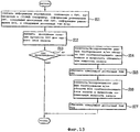
На фиг.13 показан способ записи данных на носитель записи с использованием оптического устройства записи/воспроизведения согласно первому предпочтительному варианту осуществления настоящего изобретения. В частности, на фиг.13 показан способ вычисления оптимальной мощности записи.13 shows a method of recording data on a recording medium using an optical recording / reproducing apparatus according to a first preferred embodiment of the present invention. In particular, FIG. 13 shows a method for calculating an optimal recording power.
Согласно фиг.13, если оптический диск, физическая структура которого включает в себя область OPC и область DCZ, установлен в оптическом устройстве записи/воспроизведения, микропроцессор 16 блока 20 записи/воспроизведения управляет работой блока 11 оптической головки с использованием блока 14 сервопривода, он считывает информацию управления области OPC и информацию управления области DCZ (например, "информацию размещения OPC", "следующий доступный PSN OPC", "информацию размещения DCZ" и "следующий доступный PSN DCZ"), записанную в TDMA или DMA установленного диска на этапе S11, и временно сохраняет информацию управления области OPC и информацию управления области DCZ в памяти 15.13, if an optical disk, the physical structure of which includes an OPC region and a DCZ region, is installed in the optical recording / reproducing device, the
Микропроцессор 16 выявляет правильную позицию, в которой нужно осуществлять процесс OPC, согласно вышеупомянутой информации управления на этапе S12. Микропроцессор 16 принимает команду для осуществления процесса OPC на этапе S13 и осуществляет процесс OPC в вышеуказанной позиции, выявленной с помощью информации управления. В частности, процесс OPC осуществляется в области OPC и области DCZ, что позволяет вычислять оптимальную мощность записи, подлежащую применению к установленному оптическому диску, на этапах S14 и S16. Если оптимальная мощность записи была вычислена на этапах S14 и S16, микропроцессор 16 обновляет информацию "следующего доступного PSN OPC" и информацию "следующего доступного PSN DCZ" как информацию управления, связанную с позицией следующей OPC на этапах S15 и S17. В частности, метод модуляции MSK+HMW применяется как к области OPC, пригодной для осуществления процесса OPC, так и к области DCZ, что позволяет устойчиво считывать информацию ADIP из канавочной дорожки. Физическое положение, соответствующее информации управления области OPC и информации управления области DCZ, выявляется из считанной информации ADIP на этапе S12.The
После приема команды для записи данных на соответствующий диск от контроллера 12 блок 20 записи/воспроизведения осуществляет вышеупомянутую команду записи с использованием вычисленной оптимальной мощности записи, что будет подробно описано ниже со ссылкой на фиг.14.After receiving a command to write data to a corresponding disc from the
На фиг.14 показан способ записи данных на носитель записи с использованием оптического устройства записи/воспроизведения согласно второму предпочтительному варианту осуществления настоящего изобретения.FIG. 14 shows a method of recording data on a recording medium using an optical recording / reproducing apparatus according to a second preferred embodiment of the present invention.
Согласно фиг.14 микропроцессор 16, содержащийся в блоке 20 записи/воспроизведения, принимает команду записи от контроллера 12. Команда записи состоит из данных записи и информации позиции на диске, в которую нужно произвести запись на этапе S21.According to FIG. 14, the
Таким образом, микропроцессор 16 выбирает оптимальную мощность записи, на которой нужно записывать данные, на основании информации позиции записи, содержащейся в команде записи, на этапе S22. Например, если позиция записи находится вблизи внутренней области диска, микропроцессор 16 использует оптимальную мощность записи (т.е. мощность записи, вычисленную на этапе S14), вычисленную в области OPC на этапе S23. Если позиция записи находится вблизи внешней области диска, микропроцессор 16 использует оптимальную мощность записи (т.е. мощность записи, вычисленную на этапе S16), вычисленную в области DCZ на этапе S23.Thus, the
На фиг.15 показан способ записи данных на носитель записи с использованием оптического устройства записи/воспроизведения согласно третьему предпочтительному варианту осуществления настоящего изобретения.15 shows a method of recording data on a recording medium using an optical recording / reproducing apparatus according to a third preferred embodiment of the present invention.
Согласно фиг.15, если оптический диск, физическая структура которого включает в себя область OPC и/или область DCZ, установлен в оптическом устройстве записи/воспроизведения на этапе S31, микропроцессор 16 блока 20 записи/воспроизведения, содержащийся в оптическом устройстве записи/воспроизведения, управляет работой блока 11 оптической головки с использованием блока 14 сервопривода, он считывает информацию с установленного оптического диска и определяет, форматирован ли оптический диск в процессе инициализации диска на этапе S32.15, if an optical disk whose physical structure includes an OPC region and / or a DCZ region is installed in the optical recording / reproducing device in step S31, the
Если на этапе S32 определено, что оптический диск форматирован, микропроцессор 16 осуществляет процесс OPC для вычисления оптимальной мощности записи на этапе S33.If it is determined in step S32 that the optical disk is formatted, the
Перейдем к описанию различных предпочтительных вариантов осуществления, связанных со способом осуществления процесса OPC в двухслойном оптическом диске, состоящем из двух слоев "Layer0(L0)" и "Layer1(L1)".We now turn to the description of various preferred embodiments related to the method of implementing the OPC process in a two-layer optical disk consisting of two layers “Layer0 (L0)” and “Layer1 (L1)”.
Согласно первому предпочтительному варианту осуществления настоящего изобретения осуществляется процесс OPC для вычисления оптимальной мощности записи слоя L0 с использованием области OPC0 и области DCZ0, и, одновременно, осуществляется другой процесс OPC для вычисления оптимальной мощности записи слоя L1 с использованием области OPC1 и области DCZ1. В этом случае, контроллер 12 для приема команды от пользователя может определить, в какой из областей тестирования будет сначала осуществляться процесс OPC.According to a first preferred embodiment of the present invention, an OPC process is performed to calculate the optimum recording power of the L0 layer using the OPC0 region and the DCZ0 region, and, at the same time, another OPC process is performed to calculate the optimal recording power of the L1 layer using the OPC1 region and the DCZ1 region. In this case, the
Иными словами, согласно вышеупомянутому первому предпочтительному варианту осуществления настоящего изобретения вычисляется оптимальная мощность записи области тестирования, вычисленная информация записывается в область тестирования, и вычисленная оптимальная мощность записи используется при записи данных в область данных.In other words, according to the aforementioned first preferred embodiment of the present invention, the optimum recording power of the test area is calculated, the calculated information is recorded in the testing area, and the calculated optimal recording power is used when writing data to the data area.
Согласно второму предпочтительному варианту осуществления настоящего изобретения осуществляется процесс OPC для вычисления оптимальной мощности записи с использованием области OPC0 и области DCZ0, которые выступают в качестве областей тестирования слоя L0. После приема пользовательской команды записи от контроллера 12 осуществляется процесс OPC для вычисления оптимальной мощности записи при записи данных в слой L1 в области OPC1, играющей роль области тестирования слоя L1, и в области DCZ1.According to a second preferred embodiment of the present invention, an OPC process is performed to calculate the optimum recording power using the OPC0 region and the DCZ0 region, which act as the test areas of the L0 layer. After receiving the user write command from the
В этом случае, контроллер 12 для приема команды от пользователя может определить, в какой из областей тестирования, области OPC0 или области DCZ0, будет сначала осуществляться процесс OPC.In this case, the
Согласно третьему предпочтительному варианту осуществления настоящего изобретения осуществляется процесс OPC для вычисления оптимальной мощности записи с использованием как области OPC0, играющей роль области тестирования внутренней области оптического диска, так и области OPC1, играющей роль области тестирования внутренней области. После приема пользовательской команды записи от контроллера 12 процесс OPC для вычисления оптимальной мощности записи при записи данных на оптический диск осуществляется в области DCZ0, играющей роль области тестирования внешней области 0 оптического диска, и в области DCZ1, играющий роль области тестирования внешней области 1. В этом случае, контроллер 12 для приема команды от пользователя может определить, в какой из областей тестирования, области OPC0 или области OPC1, будет сначала осуществляться процесс OPC.According to a third preferred embodiment of the present invention, an OPC process is performed to calculate the optimal recording power using both the OPC0 region, which plays the role of the test area of the inner region of the optical disc, and the OPC1 region, which plays the role of the test region of the inner region. After receiving the user write command from the
Согласно четвертому предпочтительному варианту осуществления настоящего изобретения осуществляется процесс OPC для вычисления оптимальной мощности записи с использованием области OPC0, играющей роль области тестирования внутренней области оптического диска. После приема пользовательской команды записи от контроллера 12 процесс OPC для вычисления оптимальной мощности записи при записи данных на оптический диск осуществляется в трех областях, т.е. в области DCZ0, играющей роль области тестирования внешней области 0 оптического диска, и в областях OPC1 и DCZ1, играющих роль областей тестирования слоя L1.According to a fourth preferred embodiment of the present invention, an OPC process is performed to calculate the optimal recording power using the OPC0 region, which acts as a test region of the inner region of the optical disc. After receiving the user write command from the
Согласно вышеприведенному описанию, если оптическое устройство записи/воспроизведения записывает данные на диск, играющий роль носителя записи, согласно второму предпочтительному варианту осуществления настоящего изобретения в слое L0 осуществляется процесс OPC для вычисления оптимальной мощности записи, что позволяет ему считывать данные с использованием вычисленной оптимальной мощности записи согласно информации позиции области данных, где нужно записать данные. В слое L1 осуществляется операция записи данных согласно информации позиции области данных, где нужно записать данные. В частности, при записи данных вблизи внутренней области области данных оптического диска, в слое L1 применяется оптимальная мощность записи, вычисленная путем осуществления процесса OPC в области OPC1, содержащейся во внутренней области 1. При записи данных вблизи внешней области области данных оптического диска, в слое L1 применяется оптимальная мощность записи, вычисленная путем осуществления процесса OPC в области DCZ1, содержащейся во внешней области 1. Таким образом, в слое L1 можно записывать данные с использованием одной из оптимальных мощностей записи в зависимости от позиции записи данных. Хотя вышеприведенное описание использует второй предпочтительный вариант осуществления в качестве примера различных способов, позволяющих осуществлять процесс OPC, специалистам в данной области техники очевидно, что вышеприведенное описание также применимо к другим предпочтительным вариантам осуществления, т.е. первому предпочтительному варианту осуществления, третьему предпочтительному варианту осуществления и четвертому предпочтительному варианту осуществления.According to the above description, if the optical recording / reproducing apparatus writes data to a disk playing the role of a recording medium, according to the second preferred embodiment of the present invention, an OPC process is performed in the L0 layer to calculate the optimal recording power, which allows it to read data using the calculated optimal recording power according to the position information of the data area where data is to be recorded. In the layer L1, a data recording operation is performed according to the position information of the data area where data is to be recorded. In particular, when recording data near the inner region of the data area of the optical disc, the optimal recording power calculated by performing the OPC process in the OPC region contained in the
Способ осуществления процесса OPC, когда диск, играющий роль носителя записи, является двухслойным диском, раскрыт в вышеприведенном описании. Если вышеупомянутый диск является однослойным диском, в качестве носителя записи используется только один слой записи. Поэтому, если в первом случае, когда процесс OPC осуществляется в областях OPC0 и DCZ, играющих роль областей тестирования, во втором случае, когда процесс OPC осуществляется только в области OPC0, и в третьем случае, когда процесс OPC осуществляется в области DCZ, требуется процесс OPC в течение времени использования диска, т.е., если пользовательская команда записи принимается для двухслойного оптического диска, в первом случае, втором случае и третьем случае осуществляется процесс OPC для вычисления оптимальной мощности записи, при записи данных на оптический диск. Специалистам в данной области техники очевидно, что вышеупомянутый способ осуществления процесса OPC применяется к, по меньшей мере, одному слою, играющему роль слоя записи. При условии, что на оптическом диске использовалась область тестирования для предварительного тестирования в процессе OPC на этапе S33, нужно найти начальную позицию OPC для осуществления процесса OPC в неиспользованной области тестирования. В этом случае, предпочтительно находить начальную позицию OPC с использованием способа, показанного на фиг.11. Если на этапе S32 выясняется, что диск не форматирован, блок 20 записи/воспроизведения определяет наличие или отсутствие внешней команды форматирования на этапе S34.A method for implementing an OPC process when a disc playing the role of a recording medium is a two-layer disc is disclosed in the above description. If the aforementioned disc is a single layer disc, only one recording layer is used as the recording medium. Therefore, if in the first case, when the OPC process is carried out in the OPC0 and DCZ areas, which play the role of test areas, in the second case, when the OPC process is carried out only in the OPC0 area, and in the third case, when the OPC process is performed in the DCZ area, the process is required OPC during the disk usage time, i.e., if a user write command is received for a two-layer optical disc, in the first case, the second case, and the third case, the OPC process is performed to calculate the optimal recording power when writing data to opt disk drive. Those skilled in the art will appreciate that the aforementioned method for implementing the OPC process applies to at least one layer playing the role of a recording layer. Given that the test area was used on the optical disk for preliminary testing in the OPC process in step S33, you need to find the OPC start position for the OPC process in the unused test area. In this case, it is preferable to find the starting position of the OPC using the method shown in FIG. 11. If it is determined in step S32 that the disc is not formatted, the recording / reproducing unit 20 determines the presence or absence of an external formatting command in step S34.
Если на этапе S34 определено, что команда форматирования поступила от контроллера 12, блок 20 записи/воспроизведения осуществляет процесс OPC для вычисления оптимальной мощности записи одновременно с осуществлением процесса форматирования на этапе S35. Предпочтительно осуществлять способ осуществления процесса OPC на этапе S35 таким же образом, как в вышеупомянутых предпочтительных вариантах осуществления, описанных на этапе S33. Способ осуществления процесса OPC одновременно с осуществлением процесса форматирования описан на этапе S35, что позволяет не производить тестирование для вычисления оптимальной мощности записи для записи данных на этапе S35. В этом случае, процесс OPC осуществляется в доступной позиции области тестирования.If it is determined in step S34 that the formatting command was received from the
Процесс OPC осуществляется на этапах S33 и S35, и вычисленная оптимальная мощность записи записывается в области тестирования на этапе S36.The OPC process is performed in steps S33 and S35, and the calculated optimum recording power is recorded in the test area in step S36.
Поэтому, если пользовательская команда записи/воспроизведения поступает на блок 20 записи/воспроизведения через контроллер 12, блок 20 записи/воспроизведения записывает данные на диск или воспроизводит информацию, записанную на диске, на этапе S37.Therefore, if the user recording / reproducing command is supplied to the recording / reproducing unit 20 through the
Согласно вышеприведенному описанию, предпочтительно, чтобы тест для вычисления оптимальной мощности записи только в области OPC осуществлялся на носителе записи, включающем в себя область OPC, отличную от области DCZ.According to the above description, it is preferable that the test for calculating the optimum recording power only in the OPC region is carried out on a recording medium including an OPC region other than the DCZ region.
Способ записи данных на носитель записи, когда оптическое устройство записи/воспроизведения не сразу осуществляет процесс OPC при вставлении оптического диска в оптическое устройство записи/воспроизведения, в случае, если оптический диск форматирован, будет описан ниже со ссылкой на фиг.16.A method of recording data on a recording medium when the optical recording / reproducing apparatus does not immediately carry out the OPC process when the optical disc is inserted into the optical recording / reproducing apparatus, in case the optical disc is formatted, will be described below with reference to FIG. 16.
На этапе S41, несмотря на то, что носитель записи установлен в оптическом устройстве записи/воспроизведения, блок 20 записи/воспроизведения остается в дежурном режиме, не осуществляя процесс OPC.In step S41, although the recording medium is installed in the optical recording / reproducing apparatus, the recording / reproducing unit 20 remains in standby mode without performing the OPC process.
На этапе S42 производится определение, поступила ли команда записи от контроллера 12, когда блок 20 записи/воспроизведения находится в дежурном режиме. Если определено, что команда записи поступила от контроллера 12 на этапе S42, процесс OPC осуществляется в области тестирования для осуществления операции записи данных, что позволяет вычислять оптимальную мощность записи на этапе S43. Вычисленная оптимальная мощность записи записывается в область тестирования.At step S42, it is determined whether a recording command has been received from the
Данные, пригодные для команды записи, записываются в область данных носителя записи с использованием вычисленной оптимальной мощности записи на этапе S44.Data suitable for the recording command is recorded in the data area of the recording medium using the calculated optimum recording power in step S44.
Настоящее изобретение предусматривает использование оптимальной мощности записи, вычисленной в области OPC внутренней области, при записи данных вблизи внутренней области области данных диска. При записи данных вблизи внешней области области данных оптического диска, настоящее изобретение предусматривает использование оптимальной мощности записи, вычисленной в области DCZ внешней области. Поэтому, настоящее изобретение позволяет правильно использовать оптимальную мощность записи в соответствии с позициями записи данных. Иными словами, первая оптимальная мощность записи, применяемая вблизи внутренней области диска, получается в результате вычисления в области OPC, и вторая оптимальная мощность записи, применяемая вблизи внешней области диска, получается в результате вычисления в области DCZ, что позволяет предотвращать ошибку записи данных. В этом случае, ошибка записи данных может возникать, когда одна и та же мощность записи применяется ко всем областям данных в течение заранее определенного времени записи данных, когда данные записываются на диск высокой плотности, например, BD на высокой скорости.The present invention provides for the use of the optimum recording power calculated in the OPC region of the inner region when recording data near the inner region of the disc data region. When recording data near the outer region of the optical disc data region, the present invention provides for the use of the optimum recording power calculated in the DCZ region of the outer region. Therefore, the present invention makes it possible to correctly use the optimum recording power in accordance with the data recording positions. In other words, the first optimal recording power used near the inner region of the disc is obtained by calculation in the OPC region, and the second optimal recording power applied near the outer region of the disc is obtained as a result of computation in the DCZ region, which helps to prevent a data write error. In this case, a data recording error can occur when the same recording power is applied to all data areas during a predetermined data recording time when the data is written to a high density disc, for example, BD at high speed.
В порядке другого примера, первая оптимальная мощность записи, вычисленная в области OPC, и вторая оптимальная мощность записи, вычисленная в области DCZ, не используются в примере без какого-либо изменения, но индивидуальные весовые коэффициенты применяются к первой и второй оптимальным мощностям записи в соответствии с позициями записи данных для определения последней мощности записи. Если же позиция записи данных находится вблизи центральной части области данных, среднее значение вычисленных оптимальных мощностей записи также можно применять к настоящему изобретению.In another example, the first optimal recording power calculated in the OPC area and the second optimal recording power calculated in the DCZ area are not used in the example without any change, but individual weights are applied to the first and second optimal recording powers in accordance with with data recording positions to determine the last recording power. If the data recording position is near the central part of the data region, the average value of the calculated optimal recording powers can also be applied to the present invention.
Из вышеприведенного описания следует, что физическую структуру, включающую в себя область OPC и область DCZ носителя записи, и способ и устройство для записи/воспроизведения данных на/с носителя записи, имеющего физическую структуру согласно настоящему изобретению, применимы к способу изготовления недавно разработанного BD и позволяют эффективно записывать/воспроизводить данные на/с диска.From the above description it follows that the physical structure including the OPC region and the DCZ region of the recording medium, and a method and apparatus for recording / reproducing data on / from a recording medium having a physical structure according to the present invention, are applicable to the manufacturing method of the newly developed BD and allow you to efficiently record / play data on / from the disc.
Промышленное применениеIndustrial application
Специалистам в данной области очевидно, что настоящее изобретение допускает различные модификации и вариации, не выходящие за рамки сущности и объема изобретения. Таким образом, настоящее изобретение призвано охватывать модификации и вариации данного изобретения, если они отвечают объему прилагаемой формулы изобретения и ее эквивалентов.It will be apparent to those skilled in the art that the present invention is capable of various modifications and variations without departing from the spirit and scope of the invention. Thus, the present invention is intended to cover the modifications and variations of the present invention, if they correspond to the scope of the attached claims and their equivalents.
Claims (33)
первую область тестирования, содержащуюся во внутренней области, и
вторую область тестирования, содержащуюся во внешней области,
в котором первая и вторая области тестирования формируются заранее определенным методом вобуляционной модуляции, таким же, как для области данных.1. A recording medium including an inner region, a data region, and an outer region comprising
the first area of testing contained in the inner area, and
the second area of testing contained in the external area,
in which the first and second test areas are formed by a predetermined method of wobble modulation, the same as for the data area.
(a) считывают информацию позиции, указывающую доступную область области тестирования, выделенной в носителе записи, причем информация позиции включена в информацию управления, записанную на носителе записи, и выявляют физическую позицию, соответствующую информации позиции чтения,
(b) осуществляют процесс оптимального управления мощностью (ОРС) для вычисления оптимальной мощности записи в выявленной доступной области, и
(c) записывают данные на носитель записи с использованием вычисленной оптимальной мощности записи.16. A method of recording data on a recording medium, comprising the steps of:
(a) reading position information indicating an available area of the test area allocated in the recording medium, the position information being included in the control information recorded on the recording medium, and detecting a physical position corresponding to the reading position information,
(b) carry out an optimal power control (OPC) process to calculate the optimal recording power in the identified available area, and
(c) write data to the recording medium using the calculated optimal recording power.
контроллер, выявляющий физическую позицию, соответствующую информации позиции, считанной с блока оптической головки, ищущий оптимальную мощность записи путем осуществления процесса оптимального управления мощностью (ОРС) в выявленной доступной области, и управляющий блоком оптической головки для записи данных на носитель записи с использованием найденной оптимальной мощности записи.26. A device for recording data on a recording medium containing an optical head unit that reads data recorded on a recording medium, the data including position information indicating an available area of a test area allocated in the recording medium, and wherein the position information is included in the control information recorded on the recording medium, and recording data on the recording medium, and
a controller that detects the physical position corresponding to the position information read from the optical head unit, searches for optimal recording power by performing the optimal power control (OPC) process in the detected accessible area, and controls the optical head unit for recording data on the recording medium using the found optimal power records.
Applications Claiming Priority (5)
| Application Number | Priority Date | Filing Date | Title |
|---|---|---|---|
| US60890104P | 2004-09-13 | 2004-09-13 | |
| US60/608,901 | 2004-09-13 | ||
| KR10-2005-0007014 | 2005-01-26 | ||
| KR1020050007014A KR101049132B1 (en) | 2005-01-26 | 2005-01-26 | Recording medium and recording method and recording apparatus of recording medium |
| KR10-2005-0023460 | 2005-03-22 |
Publications (2)
| Publication Number | Publication Date |
|---|---|
| RU2006136029A RU2006136029A (en) | 2008-04-20 |
| RU2376658C2 true RU2376658C2 (en) | 2009-12-20 |
Family
ID=39453688
Family Applications (1)
| Application Number | Title | Priority Date | Filing Date |
|---|---|---|---|
| RU2006136029/28A RU2376658C2 (en) | 2004-09-13 | 2005-09-12 | Recording medium and method and device for recording data onto recording medium |
Country Status (4)
| Country | Link |
|---|---|
| US (1) | US8094545B2 (en) |
| JP (1) | JP4836954B2 (en) |
| RU (1) | RU2376658C2 (en) |
| TW (1) | TWI398864B (en) |
Families Citing this family (10)
| Publication number | Priority date | Publication date | Assignee | Title |
|---|---|---|---|---|
| JP4101666B2 (en) * | 2002-01-22 | 2008-06-18 | 松下電器産業株式会社 | Information recording medium, recording apparatus, reproducing apparatus, recording method, reproducing method |
| KR101044938B1 (en) * | 2004-07-10 | 2011-06-28 | 삼성전자주식회사 | Information recording medium including a plurality of recording layers and recording?reproducing apparatus |
| US7535807B2 (en) * | 2004-09-24 | 2009-05-19 | Qisda Corporation | Method for implementing optimal recording power for multi-session recordable optical media in an optical disc drive |
| KR20070032449A (en) * | 2005-09-16 | 2007-03-22 | 삼성전자주식회사 | A optical record/ playback apparatus and method to control playback parameter |
| KR101244907B1 (en) * | 2005-09-29 | 2013-03-18 | 삼성전자주식회사 | Information recording medium in which prepit is formed and recording/reproducing apparatus and recording/reproducing method |
| JP2009543271A (en) * | 2006-07-11 | 2009-12-03 | エルジー エレクトロニクス インコーポレイティド | Recording medium, apparatus and method for recording data on the recording medium and reproducing data from the recording medium |
| JP4796551B2 (en) * | 2007-07-31 | 2011-10-19 | 太陽誘電株式会社 | Optical information reproduction system |
| US20100103793A1 (en) * | 2008-10-27 | 2010-04-29 | Panasonic Corporation | Multilayer optical information recording medium, method for recording information in the multilayer optical information recording medium, recording/reproducing apparatus |
| CN102077281A (en) * | 2008-10-27 | 2011-05-25 | 松下电器产业株式会社 | Information recording medium, recording device and reproducing device |
| US20100172226A1 (en) * | 2008-10-27 | 2010-07-08 | Panasonic Corporation | Information recording medium, reproduction apparatus and recording apparatus |
Family Cites Families (24)
| Publication number | Priority date | Publication date | Assignee | Title |
|---|---|---|---|---|
| JPH07311942A (en) * | 1994-05-16 | 1995-11-28 | Hitachi Ltd | Optical recording control system |
| TW468162B (en) * | 1999-10-13 | 2001-12-11 | Koninkl Philips Electronics Nv | Method of hiding areas on a disc like recording of the optically rewritable type |
| JP3765223B2 (en) | 2000-05-23 | 2006-04-12 | ヤマハ株式会社 | Optical disc recording method and optical disc recording apparatus |
| KR20020019638A (en) | 2000-09-06 | 2002-03-13 | 구자홍 | Optimum Power Control Method of optical recorder |
| WO2002023542A1 (en) | 2000-09-13 | 2002-03-21 | Matsushita Electric Industrial Co., Ltd. | Optical information recording medium and optical information recording method, optical information recording device |
| EP1346350A1 (en) | 2000-12-04 | 2003-09-24 | Koninklijke Philips Electronics N.V. | Method and optical recording apparatus for determining the optimum write power |
| JP2003022532A (en) * | 2001-07-06 | 2003-01-24 | Columbia Music Entertainment Inc | Optical information recording medium and method and device for optical information recording |
| JP3869743B2 (en) * | 2001-03-28 | 2007-01-17 | 松下電器産業株式会社 | Recording power determination method and recording power determination device |
| TWI224321B (en) | 2001-04-17 | 2004-11-21 | Via Tech Inc | Optimal power calibration method of optical information recorder |
| JP4652641B2 (en) | 2001-10-11 | 2011-03-16 | ソニー株式会社 | Disc recording medium, disc drive apparatus, and playback method |
| JP4121265B2 (en) | 2001-10-16 | 2008-07-23 | コーニンクレッカ フィリップス エレクトロニクス エヌ ヴィ | Disc-shaped recording medium, disc drive apparatus, disc manufacturing apparatus and method |
| JP2003168216A (en) | 2001-11-29 | 2003-06-13 | Sony Corp | Optical recording medium, and device and method for recording on the same |
| JP3847151B2 (en) | 2001-11-29 | 2006-11-15 | 株式会社リコー | Recording method and recording apparatus for phase change optical information recording medium |
| KR100635318B1 (en) * | 2002-03-15 | 2006-10-18 | 가부시끼가이샤 도시바 | Information recording medium, and information recording/reproducing device and method |
| JP4013605B2 (en) | 2002-03-22 | 2007-11-28 | ヤマハ株式会社 | Optical disc recording method and optical disc recording apparatus |
| KR100915874B1 (en) | 2002-05-01 | 2009-09-07 | 엘지전자 주식회사 | High density optical disc, and apparatus and method for reproducing a data recorded on them |
| KR100739671B1 (en) * | 2002-05-17 | 2007-07-13 | 삼성전자주식회사 | Optical disc having small access unit and method of modulating address information thereon |
| JP4295474B2 (en) | 2002-05-24 | 2009-07-15 | ソニー株式会社 | Disk recording medium, disk drive device, and disk manufacturing method |
| KR20030094730A (en) * | 2002-06-07 | 2003-12-18 | 삼성전자주식회사 | Recording medium for storing write inhibition information, recording method and write inhibition method thereof |
| JP4115173B2 (en) | 2002-06-11 | 2008-07-09 | ソニー株式会社 | Disc recording medium, disc manufacturing method, disc drive apparatus |
| JP2004103208A (en) * | 2002-07-18 | 2004-04-02 | Nec Corp | Information recording medium, method for indicator generation, manufacturing method, recording condition adjusting method, and recording method for the same medium, and information recorder |
| TWI304973B (en) | 2003-01-23 | 2009-01-01 | Lg Electronics Inc | Recording medium with copy protection information formed in intermittent or alternate wobbled pits and apparatus and methods for forming, recording, and reproducing the recording medium |
| US7286454B2 (en) * | 2003-06-30 | 2007-10-23 | Samsung Electronics Co., Ltd. | Information storage medium |
| JP4266138B2 (en) * | 2003-08-11 | 2009-05-20 | パイオニア株式会社 | Information recording apparatus and optimum laser power detection method |
-
2005
- 2005-09-12 RU RU2006136029/28A patent/RU2376658C2/en not_active IP Right Cessation
- 2005-09-12 JP JP2007531079A patent/JP4836954B2/en not_active Expired - Fee Related
- 2005-09-13 TW TW094131529A patent/TWI398864B/en not_active IP Right Cessation
- 2005-09-13 US US11/224,240 patent/US8094545B2/en not_active Expired - Fee Related
Also Published As
| Publication number | Publication date |
|---|---|
| JP4836954B2 (en) | 2011-12-14 |
| TWI398864B (en) | 2013-06-11 |
| JP2008512818A (en) | 2008-04-24 |
| RU2006136029A (en) | 2008-04-20 |
| US20060077879A1 (en) | 2006-04-13 |
| TW200625297A (en) | 2006-07-16 |
| US8094545B2 (en) | 2012-01-10 |
Similar Documents
| Publication | Publication Date | Title |
|---|---|---|
| RU2376658C2 (en) | Recording medium and method and device for recording data onto recording medium | |
| US5648954A (en) | Optical disk using land and groove tracks | |
| US8259547B2 (en) | Information storage medium and method of recording and/or reproducing with respect to the medium | |
| US8077561B2 (en) | Recording medium, apparatus for recording/reproducing data on/from the same and method thereof | |
| KR100965014B1 (en) | Optical recording medium, information processing device using the recording medium, and data recording method | |
| US9966097B2 (en) | Optical recording medium having condition management area for managing the recording condition of management information | |
| KR101053616B1 (en) | Recording medium, recording method and recording apparatus of recording medium | |
| KR101049132B1 (en) | Recording medium and recording method and recording apparatus of recording medium | |
| AU2005283190B2 (en) | Recording medium, and method and apparatus for recording data in the recording medium | |
| WO2003094162A1 (en) | Magnetooptic disk | |
| KR101111513B1 (en) | Method and Apparatus for recording data on the recording medium | |
| KR100577291B1 (en) | Optical recording medium having record capacity information and method for record capacity variable of optical recording medium and method for data recording/playing using the same | |
| KR100577274B1 (en) | Optical recording medium having record capacity information and method for record capacity variable of optical recording medium and method for data recording/playing using the same | |
| KR100578085B1 (en) | Playback Performance Improvement Method of Optical Writable Medium | |
| JP2008512817A (en) | Method and apparatus for recording data on a recording medium | |
| WO2006031039A1 (en) | Recording medium, and method and apparatus for recording data in the recording medium | |
| KR20110029307A (en) | Recording medium, data recording method, and data recording apparatus | |
| JP2002260244A (en) | Optical recording medium |
Legal Events
| Date | Code | Title | Description |
|---|---|---|---|
| MM4A | The patent is invalid due to non-payment of fees |
Effective date: 20180913 |