RU2360154C2 - Vertical rotor support - Google Patents
Vertical rotor support Download PDFInfo
- Publication number
- RU2360154C2 RU2360154C2 RU2007122080/11A RU2007122080A RU2360154C2 RU 2360154 C2 RU2360154 C2 RU 2360154C2 RU 2007122080/11 A RU2007122080/11 A RU 2007122080/11A RU 2007122080 A RU2007122080 A RU 2007122080A RU 2360154 C2 RU2360154 C2 RU 2360154C2
- Authority
- RU
- Russia
- Prior art keywords
- support
- bearing
- thrust bearing
- spherical
- radius
- Prior art date
Links
Images

Landscapes
- Sliding-Contact Bearings (AREA)
- Support Of The Bearing (AREA)
Abstract
Description
Изобретение относится к опорам быстровращающихся машин и приборов, таким как накопители энергии, гироскопы, сепараторы, центрифуги, и, в частности, к опорам вертикальных валов таких устройств.The invention relates to the supports of fast-rotating machines and devices, such as energy storage devices, gyroscopes, separators, centrifuges, and, in particular, to the supports of the vertical shafts of such devices.
Известна вертикально нагруженная опора быстровращающегося ротора по патенту US №5945754, 1999.08.31, Н02К 5/16. Опора позволяет вращать ротор с большой скоростью 800-1200 об/с и выполнена в виде иглы, на конце которой закреплен наконечник со сферической опорной поверхностью, установленной в сферическое углубление подпятника подшипника опоры, расположенного на демпфирующем элементе опоры. На поверхности сферы наконечника выполнены сферические спиральные канавки для нагнетания смазывающей жидкости между поверхностями наконечника и подпятника и отрыва поверхности наконечника от подпятника для уменьшения износа опоры.Known vertically loaded bearing of a rapidly rotating rotor according to US patent No. 5945754, 1999.08.31, H02K 5/16. The support allows the rotor to rotate at a high speed of 800-1200 r / s and is made in the form of a needle, on the end of which a tip is fixed with a spherical bearing surface mounted in a spherical recess of the bearing bearing, located on the damping element of the bearing. Spherical spiral grooves are made on the surface of the tip sphere to inject lubricating fluid between the surfaces of the tip and the thrust bearing and tear off the tip surface from the thrust bearing to reduce wear of the support.
Известная опора сложна в изготовлении и требует индивидуальной притирки сферы наконечника иглы и сферы подпятника, что создает дополнительные затраты при изготовлении и ремонте опорной пары.The known support is difficult to manufacture and requires individual grinding in the sphere of the needle tip and the thrust bearing sphere, which creates additional costs in the manufacture and repair of the support pair.
Известна вертикально нагруженная опора быстровращающегося вала по патенту UK №1212481, 1969.03.05, F16C 17/08, взятая за прототип. Вертикально нагруженная цапфа подшипника вала со скругленным по радиусу концом поддерживается в соответствующем углублении в подпятнике подшипника. В подпятнике подшипника выполнена прорезь, соединенная с каналом для отвода смазки. Радиус кривизны сферы цапфы подшипника составляет либо 2/3 от величины радиуса сферического углубления подпятника и сфера скруглена на периферии вала по меньшему радиусу, либо меньше величины радиуса сферы подпятника. На цапфе и на охватывающей цапфу втулке выполнены канавки для прокачки смазки.Known vertically loaded bearing of a rapidly rotating shaft according to UK patent No. 1212481, 1969.03.05, F16C 17/08, taken as a prototype. A vertically loaded shaft bearing journal with a radius rounded end is supported in a corresponding recess in the bearing thrust bearing. A groove is made in the bearing seat of the bearing connected to the channel for removing grease. The radius of curvature of the sphere of the journal of the bearing is either 2/3 of the radius of the spherical recess of the thrust bearing and the sphere is rounded on the periphery of the shaft to a smaller radius, or less than the radius of the sphere of the thrust bearing. Grooves for pumping grease are made on the trunnion and on the sleeve that spans the trunnion.
Известная опора имеет высокие напряжения в опорных поверхностях под вертикальной и радиальной нагрузкой при давлении меньшей сферы цапфы на большую сферу углубления подпятника, что может вызвать разрыв смазывающей пленки и износ опоры.The known bearing has high stresses in the supporting surfaces under vertical and radial loads at a pressure of a smaller spherical sphere on a large sphere of the thrust bearing, which can cause the lubricating film to rupture and the bearing to wear.
Задача, на решение которой направлено настоящее изобретение, состоит в создании простой в изготовлении опоры быстровращающегося ротора с увеличенной осевой и радиальной нагрузкой.The problem to which the present invention is directed, is to create a simple to manufacture support of a rapidly rotating rotor with increased axial and radial load.
Технический результат, достигаемый при осуществлении изобретения, заключается в повышении несущей способности опоры, снижении затрат на изготовление и ремонт опоры.The technical result achieved by the implementation of the invention is to increase the bearing capacity of the support, reducing the cost of manufacturing and repairing the support.
Технический результат достигается тем, что в опоре вертикального ротора, включающей погруженную в смазывающую жидкость опорную поверхность, выполненную на скругленном конце цапфы, установленную на опорную поверхность, выполненную в углублении подпятника опоры, опорная поверхность цапфы выполнена в виде тороидальной поверхности.The technical result is achieved by the fact that in the support of the vertical rotor, including the support surface immersed in the lubricating fluid, made on the rounded end of the spigot, mounted on the support surface, made in the recess of the foot of the support, the support surface of the spigot is made in the form of a toroidal surface.
Дополнительно, опорная поверхность подпятника выполнена в виде сферической поверхности.Additionally, the bearing surface of the thrust bearing is made in the form of a spherical surface.
Кроме того, радиус тороидальной поверхности цапфы составляет 0,4÷0,95 от величины радиуса сферической опорной поверхности подпятника.In addition, the radius of the toroidal surface of the journal is 0.4 ÷ 0.95 of the radius of the spherical bearing surface of the thrust bearing.
Дополнительно, расстояние между осевой линией тороидальной поверхности и осью цапфы составляет 0,05÷0,6 от величины радиуса сферической опорной поверхности подпятника.Additionally, the distance between the axial line of the toroidal surface and the axis of the journal is 0.05 ÷ 0.6 of the radius of the spherical bearing surface of the thrust bearing.
Кроме того, глубина сферической опорной поверхности подпятника составляет 0,7÷1,3 от величины радиуса сферической опорной поверхности подпятника.In addition, the depth of the spherical bearing surface of the thrust bearing is 0.7 ÷ 1.3 of the radius of the spherical bearing surface of the thrust bearing.
Дополнительно, торцевая поверхность цапфы выполнена плоской.Additionally, the end surface of the journal is made flat.
Кроме того, торцевая поверхность цапфы выполнена сферической с радиусом сферы, большим радиуса сферической опорной поверхности подпятника.In addition, the end surface of the trunnion is made spherical with a radius of the sphere greater than the radius of the spherical bearing surface of the thrust bearing.
Дополнительно, на тороидальной поверхности цапфы выполнены канавки, наклоненные к оси вращения в направлении нагнетания смазывающей жидкости между тороидальной и сферической опорными поверхностями.Additionally, grooves are made on the toroidal surface of the trunnion, inclined to the axis of rotation in the direction of injection of the lubricating fluid between the toroidal and spherical bearing surfaces.
Кроме того, сферическая опорная поверхность подпятника сопряжена с цилиндрической или конической поверхностью.In addition, the spherical bearing surface of the thrust bearing is associated with a cylindrical or conical surface.
Дополнительно, в подпятнике выполнен канал для прохода смазывающей жидкости, расположенный на оси вращения ротора.Additionally, in the thrust bearing there is a channel for the passage of lubricating fluid located on the axis of rotation of the rotor.
Кроме того, в подпятнике выполнен один или несколько каналов для прохода смазывающей жидкости, расположенный под углом к оси вращения ротора.In addition, one or more channels for the passage of a lubricating fluid located at an angle to the axis of rotation of the rotor are made in the thrust bearing.
Дополнительно, подпятник опоры установлен на демпфирующем элементе.Additionally, the thrust bearing is mounted on the damping element.
Кроме того, подпятник выполнен из лейкосапфира или рубина.In addition, the thrust bearing is made of leucosapphire or ruby.
Сущность изобретения поясняется прилагаемыми чертежами.The invention is illustrated by the accompanying drawings.
На фиг.1 показан вертикальный разрез общего вида опоры с демпфирующим элементом.Figure 1 shows a vertical section of a General view of the support with a damping element.
На фиг.2 дан вертикальный разрез цапфы и подпятника с обозначениями геометрии опоры.Figure 2 shows a vertical section of the trunnion and thrust bearing with the designations of the geometry of the support.
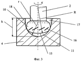
На фиг.3 показан вертикальный разрез варианта геометрии цапфы и подпятника.Figure 3 shows a vertical section of a variant of the geometry of the axle and thrust bearing.
Вертикальный ротор 1 с цапфой 2 установлен для вращения вокруг вертикальной оси 3 на подпятник 4, закрепленный на демпфирующем элементе 5. Демпфирующий элемент 5 в виде цилиндра установлен на шарнире 6 и центрирующих пружинах 7 в полости корпуса 8, заполненного смазывающей жидкостью 9. На конце цапфы 2 выполнена тороидальная опорная поверхность 10, погруженная в смазывающую жидкость 9 и опирающаяся на сферическую опорную поверхность 11, выполненную в углублении подпятника 4. Для прохода смазывающей жидкости к опорным поверхностям 10 и 11 в подпятнике 4 выполнены канал 12, расположенный на оси вращения 3, и канал 13, расположенный под углом к оси вращения 3. Тороидальная опорная поверхность 10 образована вращением вокруг оси 3 дуги окружности радиуса ρ с центром, смещенным от оси 3 на величину δ, и опирается на сферическую опорную поверхность 11 подпятника 4 с радиусом сферы r. Причем, радиус ρ тороидальной поверхности 10 цапфы 2 составляет 0,4÷0,95 от величины радиуса r сферической опорной поверхности 11 подпятника 4, так что выполняется соотношение: ρ=(0,4÷0,95)r. Расстояние δ между осевой линией тороидальной поверхности 10 и осью 3 цапфы 2 составляет 0,05÷0,6 от величины радиуса r сферической опорной поверхности 11 подпятника 4, так что выполняется соотношение: δ=(0,05÷0,6)r.A vertical rotor 1 with a
Торцевая поверхность 14 цапфы 2 в варианте опоры, показанном на фиг.2, выполнена плоской. Торцевая поверхность 15 цапфы 2 в варианте опоры, показанном на фиг.3, выполнена сферической с радиусом сферы R. Причем радиус R сферы 15 больше радиуса r сферической опорной поверхности 11 подпятника 4, так что выполняется соотношение: R>r.The
На тороидальной поверхности 10 цапфы 2 выполнены канавки 16, наклоненные к оси 3 вращения ротора 1 в направлении нагнетания смазывающей жидкости 9 между тороидальной 10 и сферической 11 опорными поверхностям.On the
Глубина h сферической опорной поверхности 11 подпятника 4 составляет 0,7÷1,3 от величины радиуса r сферической опорной поверхности 11, так что выполняется соотношение: h=(0,7÷1,3)r.The depth h of the spherical bearing
При глубине h>r сферическая опорная поверхность 11 сопряжена с цилиндрической поверхностью 17 или конической поверхностью 18 с небольшой конусностью (показана на фиг.3 пунктиром).At a depth h> r, the
Опора работает следующим образом.The support works as follows.
При отсутствии вращения ротора 1 конец цапфы 2 с тороидальной поверхностью 10 погружен в смазывающую жидкость 9 и установлен на сферической опорной поверхности 11 подпятника 4. Контактные напряжения от осевой нагрузки вертикального ротора 1 распределены между сферической опорной поверхности 11 и тороидальной поверхностью 10 по кольцевой площадке. Площадь этой площадки значительно превышает площадь пятна контакта на поверхностях известной опоры, в результате чего уровень максимальных контактных напряжений в тороидальной опоре значительно меньше, чем в опоре с непритертыми сферическими поверхностями. При вращении ротора 1 с частотой 800-1200 Гц происходит увеличение температуры смазывающей жидкости на поверхностях контакта между тороидальной поверхностью 10 и сферической опорной поверхностью 11. Меньший уровень распределенных по большей площади контактных напряжений создает более равномерное распределение температур в зоне контакта тороидальной опоры, что снижает значение максимальных температур в смазывающей жидкости и повышает работоспособность опоры. Выполнение каналов 12 и 13 в подпятнике 4 опоры обеспечивает при вращении ротора 1 проток более холодной смазывающей жидкости в зону контакта с повышенной температурой и дополнительное охлаждение опоры, а выполнение канавок 16 на тороидальной поверхности 10 увеличивает скорость циркуляции масла через зону контакта, что снижает износ опоры и увеличивает ее работоспособность.In the absence of rotation of the rotor 1, the end of the
Кроме того, при выполнении подпятника 4 из лейкосапфира или рубина в сочетании, например, со стальной тороидальной поверхностью 10 цапфы 2 опорная пара имеет малый коэффициент трения и меньшую мощность трения и температуру в опоре.In addition, when running the thrust bearing 4 from leucosapphire or ruby in combination, for example, with a steel
Сопряжение сферической опорной поверхности 11 при ее увеличенной глубине с цилиндрической поверхностью 17 или конической поверхностью 18 обеспечивает предотвращение выскакивания конца цапфы 2 из подпятника 4 при больших радиальных нагрузках взаимодействия и неустойчивых режимах работы ротора, а установка подпятника опоры на демпфирующем элементе 5 дополнительно уменьшает радиальные нагрузки.Pairing the spherical bearing
Конструкция опоры допускает изготовление опорной поверхности цапфы и подпятника без их взаимной притирки в индивидуальную пару, что снижает затраты на изготовление, а независимая установка элементов пары в опору при сборке или замене при ремонте снижает затраты на монтаж и эксплуатацию.The construction of the support allows the production of the supporting surface of the journal and the thrust bearing without lapping them into an individual pair, which reduces manufacturing costs, and the independent installation of the couple elements in the support during assembly or replacement during repair reduces installation and operation costs.
Claims (12)
Priority Applications (1)
| Application Number | Priority Date | Filing Date | Title |
|---|---|---|---|
| RU2007122080/11A RU2360154C2 (en) | 2007-06-13 | 2007-06-13 | Vertical rotor support |
Applications Claiming Priority (1)
| Application Number | Priority Date | Filing Date | Title |
|---|---|---|---|
| RU2007122080/11A RU2360154C2 (en) | 2007-06-13 | 2007-06-13 | Vertical rotor support |
Publications (2)
| Publication Number | Publication Date |
|---|---|
| RU2007122080A RU2007122080A (en) | 2008-12-20 |
| RU2360154C2 true RU2360154C2 (en) | 2009-06-27 |
Family
ID=41027392
Family Applications (1)
| Application Number | Title | Priority Date | Filing Date |
|---|---|---|---|
| RU2007122080/11A RU2360154C2 (en) | 2007-06-13 | 2007-06-13 | Vertical rotor support |
Country Status (1)
| Country | Link |
|---|---|
| RU (1) | RU2360154C2 (en) |
Cited By (2)
| Publication number | Priority date | Publication date | Assignee | Title |
|---|---|---|---|---|
| RU2489613C1 (en) * | 2012-02-13 | 2013-08-10 | Закрытое акционерное общество "Центротех-СПб" | Rotation stabilising device of vertical rotor |
| CN112160988A (en) * | 2020-10-14 | 2021-01-01 | 湖南大学 | Squeeze film damper, thrust bearing using same and use method of thrust bearing |
-
2007
- 2007-06-13 RU RU2007122080/11A patent/RU2360154C2/en not_active IP Right Cessation
Cited By (3)
| Publication number | Priority date | Publication date | Assignee | Title |
|---|---|---|---|---|
| RU2489613C1 (en) * | 2012-02-13 | 2013-08-10 | Закрытое акционерное общество "Центротех-СПб" | Rotation stabilising device of vertical rotor |
| CN112160988A (en) * | 2020-10-14 | 2021-01-01 | 湖南大学 | Squeeze film damper, thrust bearing using same and use method of thrust bearing |
| CN112160988B (en) * | 2020-10-14 | 2021-12-24 | 湖南大学 | Squeeze film damper, thrust bearing using same and use method of thrust bearing |
Also Published As
| Publication number | Publication date |
|---|---|
| RU2007122080A (en) | 2008-12-20 |
Similar Documents
| Publication | Publication Date | Title |
|---|---|---|
| EP2302239B1 (en) | Bearing device, retention mechanism and method for retaining at least one bearing pad | |
| KR100963523B1 (en) | Hybrid air foil journal bearings with external hydrostatic pressure supplies | |
| CN108302121B (en) | Tilting pad sliding bearing | |
| US20100215475A1 (en) | Vacuum Pump | |
| US6676296B2 (en) | Radial bearing and transmission using the same | |
| US20100155512A1 (en) | Thrust bearing for a gyratory crusher and method of supporting a vertical shaft in such a crusher | |
| CN102362086B (en) | Bearing device, bearing unit, and rotary machine | |
| US11828284B2 (en) | Screw compressor element and machine | |
| CN101641525A (en) | Journal bearing device | |
| RU2360154C2 (en) | Vertical rotor support | |
| RU2360155C2 (en) | Vertical rotor support | |
| JP5119281B2 (en) | Combined bearing device | |
| KR100723040B1 (en) | Bearing assembly for high speed rotary body | |
| CN210178922U (en) | Packing sealing device | |
| CN201301890Y (en) | Thrust bearing | |
| CN109958706A (en) | A kind of low-speed heave-load aligning bush(ing) bearing and its method of adjustment | |
| CN113775642A (en) | Thrust bearing and rotating shaft | |
| JP2013137100A (en) | Journal bearing, and steam turbine | |
| RU2726967C1 (en) | Protector for hydraulic protection of submersible oil-filled electric motor | |
| JP3884599B2 (en) | motor | |
| KR102557781B1 (en) | Cryogenic Bearing Test apparatus | |
| US11931744B2 (en) | Inertia cone crusher with a journal plain bearing | |
| RU2505719C1 (en) | Thrust plain bearing | |
| RU2070996C1 (en) | Bearing unit | |
| KR101877263B1 (en) | Bearing assembly having plate for removing bubbles and oil mist |
Legal Events
| Date | Code | Title | Description |
|---|---|---|---|
| MF41 | Cancelling an invention patent (total invalidation of the patent) |
Effective date: 20100927 |