RU2328074C2 - Coded multiple-input multiple-output systems with random channel inversion to be used in each natural mode - Google Patents
Coded multiple-input multiple-output systems with random channel inversion to be used in each natural mode Download PDFInfo
- Publication number
- RU2328074C2 RU2328074C2 RU2005108590/09A RU2005108590A RU2328074C2 RU 2328074 C2 RU2328074 C2 RU 2328074C2 RU 2005108590/09 A RU2005108590/09 A RU 2005108590/09A RU 2005108590 A RU2005108590 A RU 2005108590A RU 2328074 C2 RU2328074 C2 RU 2328074C2
- Authority
- RU
- Russia
- Prior art keywords
- group
- transmission channels
- transmission
- mimo
- channel
- Prior art date
Links
Images

Classifications
-
- H—ELECTRICITY
- H04—ELECTRIC COMMUNICATION TECHNIQUE
- H04W—WIRELESS COMMUNICATION NETWORKS
- H04W52/00—Power management, e.g. TPC [Transmission Power Control], power saving or power classes
- H04W52/04—TPC
- H04W52/30—TPC using constraints in the total amount of available transmission power
- H04W52/34—TPC management, i.e. sharing limited amount of power among users or channels or data types, e.g. cell loading
- H04W52/346—TPC management, i.e. sharing limited amount of power among users or channels or data types, e.g. cell loading distributing total power among users or channels
-
- H—ELECTRICITY
- H04—ELECTRIC COMMUNICATION TECHNIQUE
- H04B—TRANSMISSION
- H04B7/00—Radio transmission systems, i.e. using radiation field
- H04B7/005—Control of transmission; Equalising
-
- H—ELECTRICITY
- H04—ELECTRIC COMMUNICATION TECHNIQUE
- H04B—TRANSMISSION
- H04B7/00—Radio transmission systems, i.e. using radiation field
- H04B7/02—Diversity systems; Multi-antenna system, i.e. transmission or reception using multiple antennas
- H04B7/04—Diversity systems; Multi-antenna system, i.e. transmission or reception using multiple antennas using two or more spaced independent antennas
- H04B7/0413—MIMO systems
-
- H—ELECTRICITY
- H04—ELECTRIC COMMUNICATION TECHNIQUE
- H04L—TRANSMISSION OF DIGITAL INFORMATION, e.g. TELEGRAPHIC COMMUNICATION
- H04L1/00—Arrangements for detecting or preventing errors in the information received
- H04L1/0001—Systems modifying transmission characteristics according to link quality, e.g. power backoff
- H04L1/0002—Systems modifying transmission characteristics according to link quality, e.g. power backoff by adapting the transmission rate
- H04L1/0003—Systems modifying transmission characteristics according to link quality, e.g. power backoff by adapting the transmission rate by switching between different modulation schemes
-
- H—ELECTRICITY
- H04—ELECTRIC COMMUNICATION TECHNIQUE
- H04L—TRANSMISSION OF DIGITAL INFORMATION, e.g. TELEGRAPHIC COMMUNICATION
- H04L1/00—Arrangements for detecting or preventing errors in the information received
- H04L1/0001—Systems modifying transmission characteristics according to link quality, e.g. power backoff
- H04L1/0009—Systems modifying transmission characteristics according to link quality, e.g. power backoff by adapting the channel coding
-
- H—ELECTRICITY
- H04—ELECTRIC COMMUNICATION TECHNIQUE
- H04L—TRANSMISSION OF DIGITAL INFORMATION, e.g. TELEGRAPHIC COMMUNICATION
- H04L1/00—Arrangements for detecting or preventing errors in the information received
- H04L1/004—Arrangements for detecting or preventing errors in the information received by using forward error control
- H04L1/0041—Arrangements at the transmitter end
-
- H—ELECTRICITY
- H04—ELECTRIC COMMUNICATION TECHNIQUE
- H04L—TRANSMISSION OF DIGITAL INFORMATION, e.g. TELEGRAPHIC COMMUNICATION
- H04L1/00—Arrangements for detecting or preventing errors in the information received
- H04L1/004—Arrangements for detecting or preventing errors in the information received by using forward error control
- H04L1/0056—Systems characterized by the type of code used
- H04L1/0067—Rate matching
- H04L1/0068—Rate matching by puncturing
-
- H—ELECTRICITY
- H04—ELECTRIC COMMUNICATION TECHNIQUE
- H04L—TRANSMISSION OF DIGITAL INFORMATION, e.g. TELEGRAPHIC COMMUNICATION
- H04L1/00—Arrangements for detecting or preventing errors in the information received
- H04L1/004—Arrangements for detecting or preventing errors in the information received by using forward error control
- H04L1/0056—Systems characterized by the type of code used
- H04L1/0071—Use of interleaving
-
- H—ELECTRICITY
- H04—ELECTRIC COMMUNICATION TECHNIQUE
- H04L—TRANSMISSION OF DIGITAL INFORMATION, e.g. TELEGRAPHIC COMMUNICATION
- H04L1/00—Arrangements for detecting or preventing errors in the information received
- H04L1/02—Arrangements for detecting or preventing errors in the information received by diversity reception
- H04L1/06—Arrangements for detecting or preventing errors in the information received by diversity reception using space diversity
-
- H—ELECTRICITY
- H04—ELECTRIC COMMUNICATION TECHNIQUE
- H04B—TRANSMISSION
- H04B7/00—Radio transmission systems, i.e. using radiation field
- H04B7/02—Diversity systems; Multi-antenna system, i.e. transmission or reception using multiple antennas
- H04B7/04—Diversity systems; Multi-antenna system, i.e. transmission or reception using multiple antennas using two or more spaced independent antennas
- H04B7/0413—MIMO systems
- H04B7/0426—Power distribution
- H04B7/0434—Power distribution using multiple eigenmodes
- H04B7/0439—Power distribution using multiple eigenmodes utilizing channel inversion
-
- H—ELECTRICITY
- H04—ELECTRIC COMMUNICATION TECHNIQUE
- H04W—WIRELESS COMMUNICATION NETWORKS
- H04W52/00—Power management, e.g. TPC [Transmission Power Control], power saving or power classes
- H04W52/04—TPC
- H04W52/38—TPC being performed in particular situations
- H04W52/42—TPC being performed in particular situations in systems with time, space, frequency or polarisation diversity
Landscapes
- Engineering & Computer Science (AREA)
- Computer Networks & Wireless Communication (AREA)
- Signal Processing (AREA)
- Quality & Reliability (AREA)
- Mobile Radio Communication Systems (AREA)
- Radio Transmission System (AREA)
Abstract
Description
Область техники, к которой относится изобретениеFIELD OF THE INVENTION
Настоящее изобретение относится в целом к передаче данных, более конкретно к методикам выполнения выборочной инверсии каналов на каждой собственной моде для систем со многими входами и многими выходами.The present invention relates generally to data transmission, and more particularly to techniques for performing selective channel inversion on each eigenmode for systems with many inputs and many outputs.
Предшествующий уровень техникиState of the art
Система связи со многими входами и многими выходами (MIMO) использует множество (NT) передающих антенн и множество (NR) приемных антенн для передачи данных. Канал MIMO, сформированный NT передающими и NR приемными антеннами, может быть разложен на NS независимых каналов, причем NS≤min{NT, NR}. Каждый из NS независимых каналов также называется пространственным подканалом или собственной модой канала MIMO.A multi-input multi-output (MIMO) communication system uses multiple (N T ) transmit antennas and multiple (N R ) receive antennas for data transmission. A MIMO channel formed by N T transmit and N R receive antennas can be decomposed into N S independent channels, with N S ≤min {N T , N R }. Each of the N S independent channels is also called a spatial subchannel or a native MIMO channel mode.
Пространственные подканалы широкополосной системы MIMO могут оказаться в различных состояниях канала из-за различных факторов, таких как замирание и многолучевое распространение. Каждый пространственный подканал может, таким образом, испытывать частотно-избирательное замирание, которое характеризуется различными коэффициентами усиления канала на различных частотах полной ширины полосы системы. В предположении отсутствия управления мощностью это приводит к различным значениям отношения сигнала к шуму и помехам (SNR) на различных частотах каждого пространственного подканала, который тогда смог бы поддерживать различные скорости передачи данных для конкретного уровня качества функционирования (например, частота пакетных ошибок, равная 1%).Spatial subchannels of a MIMO broadband system may be in different channel conditions due to various factors such as fading and multipath. Each spatial subchannel can thus experience frequency selective fading, which is characterized by different channel gains at different frequencies of the full system bandwidth. Assuming no power control, this leads to different signal-to-noise and interference (SNR) values at different frequencies of each spatial subchannel, which could then support different data rates for a particular level of performance (for example, a packet error rate of 1% )
Для преодоления частотно-избирательного замирания в широкополосном канале может использоваться мультиплексирование с ортогональным разделением частот (OFDM) для эффективного разделения всей ширины полосы системы на некоторое количество (NF) поддиапазонов, которые также называются элементами разрешения по частоте или подканалами. При реализации OFDM каждый поддиапазон ассоциирован с соответствующей поднесущей, на которой могут модулироваться данные. Для системы MIMO, которая использует OFDM (т.е. системы MIMO-OFDM) каждый поддиапазон каждого пространственного подканала может рассматриваться как независимый канал передачи.To overcome frequency selective fading in a wideband channel, orthogonal frequency division multiplexing (OFDM) can be used to effectively divide the entire system bandwidth into a number of (N F ) subbands, which are also called frequency bins or subchannels. In OFDM implementation, each subband is associated with a corresponding subcarrier on which data can be modulated. For a MIMO system that uses OFDM (i.e., MIMO-OFDM systems), each subband of each spatial subchannel can be considered an independent transmission channel.
Ключевым фактором в системе кодированной связи является выбор подходящих скоростей передачи данных и схем кодирования и модуляции для использования для передачи данных на основе состояния канала. Главной целью системы является максимизирование спектральной эффективности при снижении сложности как для передатчика, так и для приемника.A key factor in a coded communication system is the selection of suitable data rates and coding and modulation schemes to use for data transmission based on channel status. The main goal of the system is to maximize spectral efficiency while reducing complexity for both the transmitter and the receiver.
Одна непосредственная методика выбора скорости передачи данных и схем кодирования и модуляции состоит в "битовой загрузке" каждого канала передачи в системе соответственно его передающей способности. Однако эта технология имеет несколько существенных недостатков. Во-первых, кодирование и модулирование отдельно для каждого канала передачи может существенно увеличить сложность обработки как на передатчике, так и на приемнике. Во-вторых, кодирование отдельно для каждого канала передачи может существенно увеличить задержку при кодировании-декодировании.One immediate technique for selecting a data rate and coding and modulation schemes is to "bit load" each transmission channel in the system according to its transmitting power. However, this technology has several significant drawbacks. Firstly, coding and modulation separately for each transmission channel can significantly increase the processing complexity at both the transmitter and the receiver. Secondly, encoding separately for each transmission channel can significantly increase the delay in encoding-decoding.
Следовательно, есть потребность в разработке технологий для достижения высокой спектральной эффективности в системах MIMO без необходимости проведения кодирования в отдельности для каждого канала передачи.Therefore, there is a need to develop technologies to achieve high spectral efficiency in MIMO systems without the need for separate coding for each transmission channel.
Сущность изобретенияSUMMARY OF THE INVENTION
Предлагаются методики для выполнения выборочной инверсии каналов на каждой собственной моде в системе MIMO для достижения высокой спектральной эффективности при снижении сложности как на передатчике, так и на приемнике. Имеющиеся каналы передачи организованы в некоторое количество групп, где каждая группа может включать в себя все каналы передачи (или элементы разрешения по частоте) для собственной моды канала MIMO. Полная передаваемая мощность распределяется по группам путем использования конкретной схемы распределения мощности (например, равномерного распределения мощности, разбавления и т.п.). Выборочная инверсия каналов затем выполняется независимо для каждой группы, выбранной для использования при передаче данных (т.е. с ненулевой выделенной передаваемой мощностью). Для каждой такой группы один или более каналов передачи в группе выбираются для использования, и масштабный коэффициент определяется для каждого выбранного канала так, чтобы все выбранные каналы для группы инвертировались и достигали одинакового качества принятого сигнала (например, SNR принятого сигнала).Methods are proposed for performing selective channel inversion on each eigenmode in the MIMO system to achieve high spectral efficiency while reducing complexity both at the transmitter and at the receiver. The existing transmission channels are organized into a number of groups, where each group can include all transmission channels (or frequency resolution elements) for the eigenmode of the MIMO channel. The total transmitted power is distributed into groups by using a specific power distribution scheme (for example, uniform power distribution, dilution, etc.). Selective channel inversion is then performed independently for each group selected for use in data transmission (i.e., with non-zero allocated transmit power). For each such group, one or more transmission channels in the group are selected for use, and a scaling factor is determined for each selected channel so that all selected channels for the group are inverted and achieve the same received signal quality (for example, SNR of the received signal).
Различные аспекты и варианты осуществления изобретения описаны ниже с дополнительными подробностями. Изобретение дополнительно предлагает способы, программные коды, процессоры цифровой обработки сигналов, блоки передатчика, блоки приемника и другие устройства и элементы, которые реализуют различные аспекты, варианты осуществления и признаки изобретения, как более подробно описано ниже.Various aspects and embodiments of the invention are described below with further details. The invention further provides methods, program codes, digital signal processing processors, transmitter units, receiver units, and other devices and elements that implement various aspects, embodiments, and features of the invention, as described in more detail below.
Перечень чертежейList of drawings
Признаки, сущность и преимущества настоящего изобретения станут более очевидны из подробного описания, изложенного ниже и взятого в сочетании с чертежами, на которых используется сквозная нумерация позиций и где:Signs, nature and advantages of the present invention will become more apparent from the detailed description set forth below and taken in conjunction with the drawings, which use the continuous numbering of positions and where:
фиг.1 - графическая иллюстрация разложения по собственным значениям для системы MIMO-OFDM;figure 1 is a graphical illustration of the expansion in eigenvalues for the MIMO-OFDM system;
фиг.2 - графики средней спектральной эффективности, достигаемой тремя схемами передачи для примера системы MIMO 4×4;figure 2 - graphs of the average spectral efficiency achieved by three transmission schemes for an example of a 4 × 4 MIMO system;
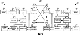
фиг.3 - структурная схема точки доступа и пользовательского терминала в системе MIMO-OFDM;FIG. 3 is a block diagram of an access point and user terminal in a MIMO-OFDM system; FIG.
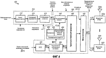
фиг.4 - структурная схема блока передатчика в точке доступа; и4 is a block diagram of a transmitter unit at an access point; and
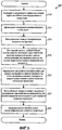
фиг.5 - блок-схема последовательности операций для обработки данных с использованием выборочной инверсии каналов на каждой собственной моде.5 is a flowchart for processing data using selective channel inversion on each eigenmode.
Подробное описаниеDetailed description
В системе связи MIMO, такой как многоантенная система беспроводной связи, потоки данных, передаваемые от NT передающих антенн, создают взаимные помехи на приемнике. Одна технология для преодоления этих помех состоит в том, чтобы "диагонализировать" канал MIMO для получения ряда независимых каналов.In a MIMO communication system, such as a multi-antenna wireless communication system, data streams transmitted from N T transmit antennas interfere with the receiver. One technology to overcome this interference is to “diagonalize” the MIMO channel to produce a number of independent channels.
Модель для системы MIMO может быть представлена выражением:The model for the MIMO system can be represented by the expression:
y= Hx + n, (1) y = Hx + n, (1)
где y - вектор с NR компонентами, {yi} при i∈{1,...,NR}, для символов, принятых NR приемными антеннами (т.е. "принятый" вектор);where y is a vector with N R components, {y i } for i∈ {1, ..., N R }, for the symbols received by N R receiving antennas (ie, the "received"vector);
x - вектор с NТ компонентами, {xj} при j∈{1,...,NТ}, для символов, переданных NТ передающими антеннами (т.е. "переданный" вектор); x is a vector with N T components, {x j } for j∈ {1, ..., N T }, for symbols transmitted by N T transmit antennas (ie, a "transmitted"vector);
H - это (NR×NТ) матрица характеристики канала, которая содержит передаточные функции (т.е. комплексные коэффициенты усиления) от NТ передающих антенн к NR приемным антеннам; и H is a (N R × N T ) channel response matrix that contains transfer functions (i.e., complex gains) from N T transmit antennas to N R receive antennas; and
n - аддитивный белый Гауссовский шум (AWGN) с вектором средних значений 0 и ковариационной матрицей Λ=σ2 I, где 0 - вектор со всеми нулями, I - единичная матрица с единицами по диагонали и нулями в остальных местах, σ2 - дисперсия шума. n is the additive white Gaussian noise (AWGN) with the
Для простоты подразумевается узкополосный канал с плавным замиранием. В этом случае характеристика канала может быть представлена постоянной комплексной величиной для всей ширины полосы системы, а элементы матрицы Н отклика канала являются скалярными величинами. Хотя здесь для простоты принимается предположение частотной неизбирательности, методики, описанные здесь, могут распространяться на частотно-избирательные каналы.For simplicity, a narrow-band fading channel is implied. In this case, the channel response can be represented by a constant complex value for the entire system bandwidth, and the elements of the channel response matrix H are scalar quantities. Although here, for simplicity, the assumption of frequency non-selectivity is accepted, the techniques described here may extend to frequency selective channels.
Матрица Н характеристики канала может быть диагонализирована путем выполнения разложения по собственным значениям корреляционной матрицы для матрицы Н, которая определяется выражением: R = H H H. Разложение по собственным значениям корреляционной матрицы R размерностью (NТ×NТ) может быть представлено как:The channel characteristic matrix H can be diagonalized by expanding the eigenvalues of the correlation matrix for the matrix H , which is determined by the expression: R = H H H. The expansion in eigenvalues of the correlation matrix R of dimension (N T × N T ) can be represented as:
R=EDE H (2) R = EDE H (2)
где Е - это унитарная матрица размерностью (NТ×NТ), столбцы которой представляют собой собственные векторы е i матрицы R, i∈{1,...,NТ};where E is a unitary matrix of dimension (N T × N T ), the columns of which are eigenvectors e i of the matrix R , i∈ {1, ..., N T };
D - это диагональная матрица размерностью (NТ×NТ) с компонентами на диагонали, соответствующими собственным значениям R и; D is a diagonal matrix of dimension (N T × N T ) with components on the diagonal corresponding to the eigenvalues of R and;
для любой матрицы М матрица М Н обозначает сопряженную транспозицию матрицы М.for any matrix M, the matrix M H denotes the conjugate transposition of the matrix M.
Унитарная матрица характеризуется свойством Е Н Е = I.The unitary matrix is characterized by the property E H E = I.
Разложение по собственным значениям может также выполняться, используя разложение по сингулярным числам матрицы (SVD), которое известно из уровня техники.Expansion in eigenvalues can also be performed using the expansion in singular matrix numbers (SVD), which is known from the prior art.
Диагональная матрица D содержит неотрицательные действительные величины по диагонали и нули в остальных местах. Эти диагональные компоненты называются собственными значениями матрицы R и указывают на коэффициенты усиления по мощности для независимых каналов канала MIMO. Число независимых каналов для системы MIMO с NТ передающими и NR приемными антеннами равно числу ненулевых собственных значений матрицы R, NS≤min{NT, NR}. Эти ненулевые собственные значения обозначаются как {λi}, i={1,...,NS}.The diagonal matrix D contains non-negative real values along the diagonal and zeros in other places. These diagonal components are called the eigenvalues of the matrix R and indicate the power gains for the independent channels of the MIMO channel. The number of independent channels for a MIMO system with N T transmit and N R receive antennas is equal to the number of nonzero eigenvalues of the matrix R , N S ≤min {N T , N R }. These nonzero eigenvalues are denoted as {λ i }, i = {1, ..., N S }.
Не учитывая ограничения по мощности для NT передающих антенн, канал может быть диагонализирован путем умножения унитарной матрицы Е слева на вектор "данных" s (или "предварительной обработки") для получения переданного вектора х. Предварительная обработка на передатчике может быть выражена как:Without considering the power limitations for N T transmit antennas, the channel can be diagonalized by multiplying the unitary matrix E on the left by the vector of “data” s (or “preprocessing”) to obtain the transmitted vector x . Pre-processing at the transmitter can be expressed as:
х = Es (3) x = Es (3)
На приемнике принятый вектор y может быть умножен справа на Е Н Н Н (или "обработан") для получения оценки вектора s данных. Обработка для получения оценки s вектора данных может быть выражена как:At the receiver, the received vector y can be multiplied to the right by E H N H (or “processed”) to obtain an estimate of the data vector s . Processing to obtain an estimate s of the data vector can be expressed as:

где ![]()
![]()
![]()
![]()
Как показано в уравнении (4), предварительная обработка на передатчике и обработка на приемнике приводят к тому, что вектор s данных преобразуется посредством эффективной характеристики канала, представленной матрицей D, а также к масштабированию шумовых элементов. Так как D является диагональной матрицей, фактически есть NS не создающих взаимных помех параллельных каналов. Каждый из этих каналов имеет коэффициент усиления, равный квадрату соответствующего собственного значения, λi 2, и мощность шума, равную σ2λi, i∈{1,...,NS}, что дает отношение сигнала к шуму, равное λi/σ2. Таким образом, коэффициент усиления мощности каждого из этих каналов равен собственному значению λi, i∈{1,...,NS}. Параллельный канал i часто называют собственной модой i или модой i. Диагонализация канала MIMO, как показано в уравнениях (3) и (4), может быть достигнута, если передатчик обеспечен матрицей Н характеристики канала или эквивалентной информацией.As shown in equation (4), pre-processing at the transmitter and processing at the receiver cause the data vector s to be transformed by the effective channel response represented by matrix D , as well as scaling the noise elements. Since D is a diagonal matrix, in fact there are N S non-interfering parallel channels. Each of these channels has a gain equal to the square of the corresponding eigenvalue, λ i 2 , and a noise power equal to σ 2 λ i , i∈ {1, ..., N S }, which gives a signal to noise ratio equal to λ i / σ 2 . Thus, the power gain of each of these channels is equal to the eigenvalue λ i , i∈ {1, ..., N S }. Parallel channel i is often called native mode i or mode i. MIMO channel diagonalization, as shown in equations (3) and (4), can be achieved if the transmitter is provided with a channel characteristic matrix H or equivalent information.
Разложение по собственным значениям, описанное выше, может также выполняться для широкополосного частотно-избирательного канала. Для системы MIMO-OFDM широкополосный канал делится на NF ортогональных элементов разрешения по частоте c плавным замиранием, или поддиапазонов. Разложение по собственным значениям может тогда выполняться независимо для матрицы Н(k) характеристики канала для каждого элемента разрешения по частоте, k, для определения NS пространственных подканалов или собственных мод для этого элемента разрешения по частоте. Каждый пространственный подканал каждого элемента разрешения по частоте называется также каналом "передачи".The eigenvaluation described above can also be performed for a broadband frequency-selective channel. For a MIMO-OFDM system, the broadband channel is divided into N F orthogonal frequency bins with fading, or subbands. Eigenvalue decomposition can then be performed independently for the channel characteristic matrix H (k) for each frequency resolution element, k, to determine N S spatial subchannels or eigenmodes for this frequency resolution element. Each spatial subchannel of each frequency resolution element is also called a “transmit” channel.
Модель системы MIMO-OFDM может также выражаться следующей формулой:The MIMO-OFDM system model can also be expressed by the following formula:
y(k)=H(k)x(k) + n(k), k∈{1,...,NF} (5) y (k) = H (k) x (k) + n (k), k∈ {1, ..., N F } (5)
где "(k)" означает k-ый элемент разрешения по частоте.where "(k)" means the kth element of the frequency resolution.
Разложение по собственным значениям корреляционной матрицы R(k) для каждого элемента разрешения по частоте может выражаться как:The expansion in eigenvalues of the correlation matrix R (k) for each frequency resolution element can be expressed as:
R(k)=E(k)D(k)E H(k) (6) R (k) = E (k) D (k) E H (k) (6)
Ненулевые собственные значения для R(k) обозначены как {λi(k)}, i={1,...,NS} и k={1,...,NF}. Таким образом, для системы MIMO-OFDM разложение по собственным значениям для каждого из NF элементов разрешения по частоте приводит к NS пространственным подканалам или собственным модам для каждого элемента разрешения по частоте, или к общему количеству NSNF каналов передачи.Nonzero eigenvalues for R (k) are denoted by {λ i (k)}, i = {1, ..., N S } and k = {1, ..., N F }. Thus, for an MIMO-OFDM system, eigenvaluation for each of the N F frequency bins results in N S spatial subchannels or eigenmodes for each frequency bins or in the total number of N S N F transmission channels.
Собственные значения могут предоставляться в двух формах - в "сортированной" форме и форме "произвольного порядка". В сортированной форме NS собственных значений каждого элемента разрешения по частоте отсортированы в убывающем порядке так, что {λ1(k)≥λ2(k)≥ ... ≥λNs(k)}, где λ1(k) - самое большое собственное значение для элемента k разрешения по частоте и λNs(k) - самое малое собственное значение для элемента k разрешения по частоте. В форме произвольного порядка упорядочение собственных значений может быть произвольным и, кроме того, независимым от частоты. Конкретная форма, выбранная для использования, сортированная или произвольно-упорядоченная, влияет на выбор собственных мод для использования для передачи данных и схемы кодирования и модуляции, которая будет использоваться для каждой выбранной собственной моды, как описано ниже.Eigenvalues can be provided in two forms - in the "sorted" form and in the "arbitrary order" form. In the sorted form N S of the eigenvalues of each element, the frequency resolutions are sorted in decreasing order so that {λ 1 (k) ≥λ 2 (k) ≥ ... ≥λ Ns (k)}, where λ 1 (k) - the largest eigenvalue for the frequency resolution element k and λ Ns (k) is the smallest eigenvalue for the frequency resolution element k. In the form of an arbitrary order, the ordering of the eigenvalues can be arbitrary and, moreover, independent of frequency. The particular form selected for use, sorted or randomly ordered, affects the choice of eigenmodes to use for data transmission and the coding and modulation scheme that will be used for each selected eigenmodes, as described below.
Фиг.1 графически представляет разложение по собственным значениям для системы MIMO-ОМЧР. Набор диагональных матриц D(k), k={1,...,NF} показан расположенным в порядке вдоль оси 110, которая представляет частотное измерение. Собственные значения {λi(k)}, i={1,...,NS}, каждой матрицы D(k) расположены по диагонали матрицы. Ось 112 может, таким образом, рассматриваться как представляющая пространственное измерение. Собственная мода i для всех элементов разрешения по частоте (или просто собственная мода i) соотносится с набором элементов, {λi(k)} при k={1,...,NF}, который характеризует частотную характеристику по всем NF элементам разрешения по частоте для этой собственной моды. Набор элементов {λi(k)} для каждой собственной моды показан заштрихованными квадратами вдоль пунктирной линии 114. Каждый заштрихованный квадрат на Фиг.1 представляет канал передачи. Для каждой собственной моды, которая испытывает частотно-избирательное замирание, элементы {λi(k)} для этой собственной моды могут быть различными для различных значений k.1 graphically represents an eigenvalue decomposition for a MIMO-OFDM system. The set of diagonal matrices D (k), k = {1, ..., N F } is shown arranged in order along axis 110, which represents a frequency measurement. The eigenvalues {λ i (k)}, i = {1, ..., N S }, of each matrix D (k) are located on the diagonal of the matrix. The axis 112 may thus be considered as representing a spatial dimension. The eigenmode i for all frequency resolution elements (or just the eigenmode i) corresponds to a set of elements, {λ i (k)} for k = {1, ..., N F }, which characterizes the frequency response over all N F frequency resolution elements for this native mode. The set of elements {λ i (k)} for each eigenmode is shown by shaded squares along the dashed line 114. Each shaded square in FIG. 1 represents a transmission channel. For each eigenmode that experiences frequency selective fading, the elements {λ i (k)} for this eigenmode can be different for different values of k.
Если собственные значения каждой диагональной матрицы D(k) отсортированы в порядке убывания, то собственной моде 1 (которая также называется главной собственной модой) будет соответствовать самое большое собственное значение λ1(k) в каждой матрице, а собственная мода NS будет включать самое малое собственное значение, λNs(k), в каждой матрице.If the eigenvalues of each diagonal matrix D (k) are sorted in descending order, then the eigenmode 1 (also called the main eigenmode) will correspond to the largest eigenvalue λ 1 (k) in each matrix, and the eigenmode N S will include the most small eigenvalue, λ Ns (k), in each matrix.
В результате разложения по собственным значениям для каждого элемента разрешения по частоте в системе MIMO-ОМЧР получают всего NSNF собственных значений для NSNF каналов передачи по всей ширине полосы. Каждый канал передачи может достигать различного SNR и может иметь различные возможности передачи. Разнообразные схемы распределения мощности (или схемы передачи) могут использоваться для распределения всей передаваемой мощности по этим каналам передачи для достижения высокой общей спектральной эффективности, которая выражается в битах в секунду на Герц (бит/с/Гц). Некоторые из этих схем описаны более подробно ниже.As a result of eigenvalue decomposition for each frequency resolution element in the MIMO-OFDM system, a total of N S N F eigenvalues are obtained for N S N F transmission channels over the entire bandwidth. Each transmission channel may achieve a different SNR and may have different transmission capabilities. A variety of power distribution schemes (or transmission schemes) can be used to distribute all the transmitted power over these transmission channels to achieve a high overall spectral efficiency, which is expressed in bits per second per Hertz (bit / s / Hz). Some of these schemes are described in more detail below.
1. Разбавление1. Dilution
Схема "разбавления" может использоваться для оптимального распределения всей передаваемой мощности по каналам передачи так, что общая эффективность использования спектральной полосы максимизируется, при ограничении, что полная передаваемая мощность на передатчике ограничена величиной Ptotal. Схема разбавления распределяет мощность по NSNF каналам передачи так, что каналы с более высокими значениями SNR получают большие доли общей передаваемой мощности. Передаваемая мощность, выделенная заданному каналу передачи, определяется SNR данного канала, которое задается величиной λi (k)/σ 2, где λi(k) - i-е собственное значение в k-м элементе разрешения по частоте.The dilution scheme can be used to optimally distribute all the transmitted power over the transmission channels so that the overall efficiency of the use of the spectral band is maximized, while limiting that the total transmitted power at the transmitter is limited to P total . The dilution scheme distributes the power over the N S N F transmission channels so that channels with higher SNRs receive large fractions of the total transmitted power. The transmitted power allocated to a given transmission channel is determined by the SNR of this channel, which is given by the value λ i (k) / σ 2 , where λ i (k) is the ith eigenvalue in the kth frequency resolution element.
Процедура выполнения разбавления известна из уровня техники и не описывается здесь. Результатом разбавления является характерное распределение передаваемой мощности в каждом из NSNF каналов передачи, которое обозначается как Pi(k), i={1,...,NS} и k={1,...,NF}. Распределение мощности выполняется так, чтобы удовлетворялось следующее условие:The dilution procedure is known in the art and is not described here. The result of dilution is the characteristic distribution of transmitted power in each of the N S N F transmission channels, which is denoted by P i (k), i = {1, ..., N S } and k = {1, ..., N F }. Power distribution is performed so that the following condition is satisfied:

где L ={1,...,NS} и K={1,...,NF}.where L = {1, ..., N S } and K = {1, ..., N F }.
На основе распределенных передаваемых мощностей Pi(k) при i={1,...,NS} и k={1,...,NF} SNR принятого сигнала, γi(k) для каждого канала передачи может быть выражено следующим образом:Based on the distributed transmitted powers P i (k) for i = {1, ..., N S } and k = {1, ..., N F } SNR of the received signal, γ i (k) for each transmission channel can be expressed as follows:

Общая спектральная эффективность С для NSNF каналов передачи может быть затем вычислена на основе непрерывной монотонно возрастающей логарифмической функции для пропускной способности:The total spectral efficiency C for N S N F transmission channels can then be calculated based on a continuous monotonically increasing logarithmic function for throughput:

В типичной схеме связи полный диапазон значений SNR принятых сигналов, которые, как ожидается, будут наблюдаться, может быть разделен на ряд поддиапазонов. Каждый поддиапазон может затем быть соотнесен с конкретной схемой кодирования и модуляции, выбранной для получения самой высокой спектральной эффективности при заданной частоте ошибок по битам (BER), частоте кадровых ошибок (FER) или частоте пакетных ошибок (PER). Распределение мощности, соответствующее разбавлению может привести к различным значениям SNR принятых сигналов для каждого из NSNF каналов передачи. Это привело бы тогда к использованию многих различных схем кодирования/модуляции для каналов передачи. Кодирование/модуляция на каждый канал передачи увеличивает спектральную эффективность за счет большей сложности как для передатчика, так и для приемника.In a typical communication scheme, the full range of SNR values of the received signals that are expected to be observed can be divided into a number of subbands. Each subband can then be associated with a particular coding and modulation scheme selected to obtain the highest spectral efficiency for a given bit error rate (BER), frame error rate (FER), or packet error rate (PER). A power distribution corresponding to dilution can result in different SNR values of the received signals for each of the N S N F transmission channels. This would then lead to the use of many different coding / modulation schemes for transmission channels. Coding / modulation for each transmission channel increases spectral efficiency due to greater complexity for both the transmitter and the receiver.
2. Выборочная инверсия канала, примененная ко всем каналам передачи2. Selective channel inversion applied to all transmission channels
Схема "Выборочной инверсии канала (ВИК, SCI)-для-всех-каналов" выполняет выборочную инверсию канала (ВИК) на всех каналах передачи так, чтобы те каналы, которые выбраны для использования, достигали приблизительно равных значений SNR принятых сигналов на приемнике. Это позволило бы использовать общую схему кодирования и модуляции для всех выбранных каналов передачи. Эта схема существенно снижает сложность как для передатчика, так и для приемника по сравнению со схемой разбавления. Уравнивание значений SNR принятых сигналов может достигаться сначала выбором всех или только подмножества из NSNF имеющихся каналов передачи для использования для передачи данных. Выбор каналов может приводить к исключению плохих каналов с низкими значениями SNR. Полная передаваемая мощность Ptotal тогда распределяется по выбранным каналам таким образом, что SNR принятого сигнала приблизительно одинаково для всех выбранных каналов передачи.The Selective Channel Inversion (VIC, SCI) -all-channels scheme performs selective channel inversion (VIC) on all transmission channels so that those channels selected for use achieve approximately equal SNR values of the received signals at the receiver. This would allow the use of a common coding and modulation scheme for all selected transmission channels. This scheme significantly reduces the complexity for both the transmitter and receiver compared to the dilution scheme. Alignment of the SNR values of the received signals can be achieved first by selecting all or only a subset of the N S N F available transmission channels for use for data transmission. Channel selection can eliminate bad channels with low SNRs. The total transmitted power P total is then distributed over the selected channels so that the SNR of the received signal is approximately the same for all selected transmission channels.
Если выполняется "полная" инверсия каналов для всех NSNF имеющихся каналов передачи, то полная передаваемая мощность Ptotal может быть распределена так, что приблизительно одинаковая мощность сигнала получается для всех этих каналов. Приблизительная величина передаваемой мощности Pi(k) для выделения i-ой собственной моде k-го элемента разрешения по частоте может выражаться как:If a “complete” channel inversion is performed for all N S N F available transmission channels, then the total transmitted power P total can be distributed so that approximately the same signal power is obtained for all these channels. The approximate value of the transmitted power P i (k) for highlighting the i-th eigenmode of the k-th frequency resolution element can be expressed as:

где α - это нормировочный множитель, используемый для распределения полной передаваемой мощности между имеющимися каналами передачи. Этот нормировочный множитель α может быть выражен как:where α is the normalization factor used to distribute the total transmitted power between the available transmission channels. This normalization factor α can be expressed as:

Нормировочный множитель α обеспечивает приблизительно одинаковую мощность принятого сигнала для всех каналов передачи, которая дается величиной αPtotal. Полная передаваемая мощность таким образом эффективно распределяется (неравномерно) по всем имеющимся каналам передачи на основе их коэффициентов усиления по мощности, которые задаются собственными значениями λi(k).The normalization factor α provides approximately the same received signal power for all transmission channels, which is given by the value αP total . The total transmitted power is thus effectively distributed (unevenly) across all available transmission channels based on their power gains, which are set by the eigenvalues λ i (k).
Если выполняется "выборочная" инверсия каналов, то только те каналы передачи, значения принимаемой мощности которых находятся на уровне или выше определенного порога β относительно полной принимаемой мощности, выбираются для использования для передачи данных. Каналы передачи, уровни принимаемой мощности для которых попадают в диапазон ниже этого порога, отвергаются и не используются. Для каждого выбранного канала передачи передаваемая мощность, которая должна выделяться этому каналу, определяется как описано выше, так, чтобы все выбранные каналы передачи принимались при приблизительно одинаковом уровне мощности. Порог β может быть выбран так, чтобы максимизировать спектральную эффективность, или на основе каких-либо других критериев.If a “selective” channel inversion is performed, then only those transmission channels whose received power values are at or above a certain threshold β relative to the total received power are selected for use for data transmission. Transmission channels for which received power levels fall below this threshold are rejected and not used. For each selected transmission channel, the transmitted power to be allocated to that channel is determined as described above, so that all selected transmission channels are received at approximately the same power level. The threshold β may be selected so as to maximize spectral efficiency, or based on any other criteria.
Выбор каналов передачи для использования может осуществляться следующим образом. Сначала средний коэффициент Pavg усиления по мощности вычисляется для всех имеющихся каналов передачи и может быть выражен следующим образом:The choice of transmission channels for use can be as follows. First, the average power gain P avg is calculated for all available transmission channels and can be expressed as follows:

Передаваемая мощность, подлежащая выделению каждому каналу передачи, может быть выражена как:The transmitted power to be allocated to each transmission channel can be expressed as:

где β - это порог и ![]()
![]()
![]()
![]()

Порог β может быть получен, как описано ниже (в разделе 3.2.)The threshold β can be obtained as described below (in section 3.2.)
Как показано в уравнении (13), канал передачи выбирается для использования, если его собственное значение (или коэффициент усиления канала по мощности) больше или равно порогу мощности (т.е. λi(k)βPavg). Так как нормированный множитель ![]()
![]()
![]()
![]()
Уравнивание значений SNR принятых сигналов для всех выбранных каналов передачи может, таким образом, быть достигнуто путем неравномерного распределения полной передаваемой мощности по этим каналам. Приблизительно равные значения SNR принятых сигналов позволили бы использовать одну скорость передачи данных и общую схему кодирования/модуляции для всех выбранных каналов передачи, что значительно снизило бы сложность.The equalization of the SNR values of the received signals for all selected transmission channels can thus be achieved by uneven distribution of the total transmitted power over these channels. Approximately equal SNR values of the received signals would allow the use of one data rate and a common coding / modulation scheme for all selected transmission channels, which would significantly reduce complexity.
3. Выборочная инверсия каналов, примененная на каждой собственной моде 3. Selected channel inversion applied on each own mode
Схема "ВИК-на-каждой-собственной моде" выполняет выборочную инверсию каналов независимо для каждой собственной моды для обеспечения улучшенного функционирования. В варианте осуществления NSNF каналов передачи организованы в NS групп так, что каждая группа включает в себя все NF элементов разрешения по частоте для заданной собственной моды (т.е. группа i включает в себя пространственные подканалы для всех NF элементов разрешения по частоте для собственной моды i). Таким образом, есть одна группа для каждой собственной моды.The VIC-on-each-eigenmode circuit performs selective channel inversion independently for each eigenmode to provide improved performance. In an embodiment, N S N F transmission channels are organized into N S groups so that each group includes all N F frequency resolution elements for a given eigenmode (i.e., group i includes spatial subchannels for all N F elements frequency resolutions for eigenmode i). Thus, there is one group for each own fashion.
Схема "ВИК-на-каждой-собственной моде" включает в себя два этапа. На первом этапе полная передаваемая мощность Ptotal распределяется по NS группам на основе конкретной схемы распределения мощности. На втором этапе выборочная инверсия каналов выполняется независимо для каждой группы для распределения выделенной в этой группе передаваемой мощности по NF элементам разрешения по частоте в этой группе. Каждый из этих этапов описан более подробно ниже.The VIC-on-every-own fashion scheme includes two steps. At the first stage, the total transmitted power P total is distributed among N S groups based on a specific power distribution scheme. At the second stage, selective channel inversion is performed independently for each group to distribute the transmitted power allocated in this group among N F frequency resolution elements in this group. Each of these steps is described in more detail below.
3.1. Распределение мощности по группам 3.1. Power distribution by groups
Полная передаваемая мощность Ptotal может быть распределена по NS группам различными путями, некоторые из которых описаны ниже.The total transmitted power P total can be distributed among N S groups in various ways, some of which are described below.
В первом варианте осуществления полная передаваемая мощность Ptotal распределяется равномерно по всем NS группам так, чтобы всем им была выделена одинаковая мощность. Передаваемая мощность PG(i), выделенная каждой группе, может быть выражена как:In the first embodiment, the total transmitted power P total is distributed evenly across all N S groups so that all of them are allocated the same power. The transmitted power P G (i) allocated to each group can be expressed as:

Во втором варианте осуществления полная передаваемая мощность Ptotal распределяется по NS группам на основе разбавления по всем имеющимся каналам передачи. Для этого варианта осуществления полная передаваемая мощность Ptotal сначала распределяется по всем NSNF каналам передачи, используя разбавление, как описано выше. На каждый канал передачи выделяется Pi(k), i∈{1,...,NS} и k∈{1,...,NF}. Передаваемая мощность, выделенная каждой группе, может затем быть определена путем суммирования по передаваемым мощностям, выделенным NF каналам передачи в этой группе. Передаваемая мощность, выделенная группе i, может быть выражена как:In a second embodiment, the total transmitted power P total is distributed among N S groups based on dilution across all available transmission channels. For this embodiment, the total transmitted power P total is first distributed across all N S N F transmission channels using dilution as described above. For each transmission channel, P i (k), i∈ {1, ..., N S } and k∈ {1, ..., N F } are allocated. The transmitted power allocated to each group can then be determined by summing the transmitted powers allocated to the N F transmission channels in this group. The transmitted power allocated to group i can be expressed as:

В третьем варианте осуществления полная передаваемая мощность Ptotal распределяется по NS группам на основе разбавления по всем группам, используя их средние по каналам значения SNR. Исходно среднее по каналам SNR, γavg(i), для каждой группы определяется как:In the third embodiment, the total transmitted power P total is distributed among N S groups based on dilution across all groups using their channel average SNRs. Initially, the average of the SNR channels, γ avg (i), for each group is determined as:

Затем выполняется разбавление для распределения полной передаваемой мощности Ptotal по NS группам на основе их средних по каналам значений SNR. Передаваемая мощность, выделенная каждой из NS групп, обозначается как PG(i), i∈{1,...,NS}.Then dilution is performed to distribute the total transmitted power P total among the N S groups based on their channel average SNRs. The transmitted power allocated to each of the N S groups is denoted by P G (i), i∈ {1, ..., N S }.
В четвертом варианте осуществления полная передаваемая мощность Ptotal распределяется по NS группам на основе разбавления по всем группам, используя значения SNR принятых сигналов каналов передачи после инверсии каналов. В этом варианте осуществления полная передаваемая мощность Ptotal сначала распределяется равномерно по NS группам, как показано выше в уравнении (15), так, что каждой группе выделяется начальное значение передаваемой мощности ![]()
![]()
![]()
![]()
![]()
![]()
![]()
![]()
![]()
![]()

Затем полная передаваемая мощность Ptotal распределяется по NS группам, используя разбавление на основе их средних значений SNR принятого сигнала ![]()
![]()
Нет необходимости выполнять вторую выборочную инверсию каналов для заданной группы, если (1) пересмотренная передаваемая мощность, выделенная группе посредством разбавления, превышает начальное равномерное распределение мощности (т.е. ![]()
![]()

Уравнение (19) может использоваться, потому что (1) все элементы разрешения по частоте в группе уже были выбраны для использования, и никакой дополнительный элемент разрешения по частоте не может быть выбран, даже если пересмотренное распределение PG(i) мощности для группы по значению превышает начальное распределение мощности ![]()
![]()
3.2. Выборочная инверсия каналов, примененная к каждой группе 3.2. Selective channel inversion applied to each group
После того, как полная передаваемая мощность Ptotal распределена по NS группам, используя любую из описанных выше схем распределения мощности по группам, выборочная инверсия каналов выполняется независимо для каждой из NS групп и на NF элементах разрешения по частоте внутри каждой группы. Выборочная инверсия каналов для каждой группы может быть выполнена следующим образом.After the total transmitted power P total is distributed across N S groups using any of the power distribution schemes described above for groups, selective channel inversion is performed independently for each of N S groups and on N F frequency resolution elements within each group. Selective channel inversion for each group can be performed as follows.
Сначала определяют средний коэффициент усиления по мощности, Pavg(i), для каждой группы как:First determine the average power gain, P avg (i), for each group as:

Передаваемая мощность, выделенная k-ому элементу разрешения по частоте в группе i, может быть выражена как:The transmitted power allocated to the k-th frequency resolution element in group i can be expressed as:

где βi - это порог, а ![]()
![]()
![]()
![]()

Суммирование коэффициентов усиления мощности инверсных каналов в уравнении (22) принимает во внимание коэффициенты усиления каналов по всем выбранным элементам разрешения по частоте группы i.The summation of the power gain of the inverse channels in equation (22) takes into account the gain of the channels for all selected frequency resolution elements of group i.
Порог βi для отбора элементов разрешения по частоте для использования в каждой группе может быть установлен на основе различных критериев, например, так, чтобы оптимизировать спектральную эффективность. В одном варианте осуществления порог βi устанавливается на основе коэффициентов усиления мощности канала (или собственных значений) и показателей спектральной эффективности для выбранных элементов разрешения по частоте на основе равномерного распределения передаваемой мощности по элементам разрешения по частоте в каждой группе, как описано ниже.The threshold β i for selecting frequency resolution elements for use in each group can be set based on various criteria, for example, so as to optimize spectral efficiency. In one embodiment, the threshold β i is set based on the channel power gain (or eigenvalues) and spectral efficiency indicators for the selected frequency resolution elements based on the uniform distribution of the transmitted power among the frequency resolution elements in each group, as described below.
Для этого варианта осуществления определение значения порога βi для группы i происходит следующим образом (причем это определение выполняется независимо для каждой группы). Сначала собственные значения для всех NF элементов разрешения по частоте в группе ранжируются и размещаются в списке Gi(λ), λ∈{1,...,NF}, в порядке убывания, так что Gi(1)=max{λi(k)} и Gi(NF)=min{λi(k)} i∈{1,...,NS}.For this embodiment, the determination of the threshold value β i for group i occurs as follows (moreover, this determination is performed independently for each group). First, the eigenvalues for all N F frequency resolution elements in the group are ranked and placed in the list G i (λ), λ∈ {1, ..., N F }, in decreasing order, so that G i (1) = max {λ i (k)} and G i (N F ) = min {λ i (k)} i∈ {1, ..., N S }.
Для каждого λ, где λ∈{1,...,NF}, вычисляется эффективность использования спектральной полосы для λ лучших элементов разрешения по частоте, где слово "лучшие" относится к элементам разрешения, по частоте с самыми высокими коэффициентами усиления по мощности, Gi(λ). Это может быть достигнуто следующим образом. Во-первых, полная передаваемая мощность, доступная для групп, PG(i), распределяется по λ лучшим элементам разрешения по частоте, используя любую из описанных выше схем распределения мощности. Для простоты используется схема равномерного распределения мощности, и передаваемая мощность для каждого из λ элементов разрешения по частоте составляет PG(i)/λ. Затем SNR принятого сигнала для каждого из λ элементов разрешения по частоте вычисляется по формуле:For each λ, where λ∈ {1, ..., N F }, the spectral band efficiency for λ best frequency resolution elements is calculated, where the word "best" refers to frequency resolution elements with the highest power gains , G i (λ). This can be achieved as follows. Firstly, the total transmitted power available for the groups, P G (i), is distributed over the λ best frequency resolution elements using any of the power distribution schemes described above. For simplicity, a uniform power distribution scheme is used, and the transmitted power for each of λ frequency resolution elements is P G (i) / λ. Then, the SNR of the received signal for each of the λ frequency elements is calculated by the formula:

Затем спектральная эффективность Сi(λ) для λ лучших элементов разрешения по частоте в группе i вычисляется по формуле:Then the spectral efficiency C i (λ) for λ the best frequency resolution elements in group i is calculated by the formula:

где ρ - это масштабный коэффициент, используемый для того, чтобы учитывать недостатки схемы кодирования и модуляции, выбранной для использования.where ρ is the scale factor used to take into account the disadvantages of the coding and modulation scheme selected for use.
Спектральная эффективность Сi(λ) вычисляется для каждого значения λ, где λ∈{1,...,NF}, и сохраняется в массиве. После того, как все NF значений Сi(λ) вычислены для NF возможных комбинаций выбранных элементов разрешения по частоте, просматривается массив значений спектральной эффективности, и определяется самое большое значение Сi(λ). Тогда значение λ, λmax, соответствующее самому большому значению Сi(λ), представляет собой количество элементов разрешения по частоте, которое обеспечивает максимальную спектральную эффективность для оцениваемых состояний канала и при использовании равномерного распределения передаваемой мощности.The spectral efficiency C i (λ) is calculated for each value of λ, where λ∈ {1, ..., N F }, and is stored in the array. After all N F values of C i (λ) are calculated for N F possible combinations of selected frequency resolution elements, an array of spectral efficiency values is scanned and the largest value of C i (λ) is determined. Then the value of λ, λ max , corresponding to the largest value of C i (λ), is the number of frequency resolution elements that provides maximum spectral efficiency for the estimated channel conditions and when using uniform distribution of transmitted power.
Поскольку собственные значения для NF элементов разрешения по частоте в группе i ранжируются в порядке убывания в списке Gi(λ), спектральная эффективность увеличивается по мере того, как для использования выбираются больше элементов разрешения по частоте, пока не достигается оптимальная точка, после которой спектральная эффективность уменьшается, так как больше от передаваемой мощности данной группы выделяется худшим элементам разрешения по частоте. Таким образом, вместо вычисления спектральной эффективности Сi(λ) для всех возможных значений λ, спектральная эффективность Сi(λ) для каждого нового значения λ может сравниваться со спектральной эффективностью Сi(λ-1) для предыдущего значения λ. Вычисление может быть закончено, если достигнута оптимальная спектральная эффективность, которая определяется тем, что Сi(λ)<Сi(λ-1).Since the eigenvalues for N F frequency resolution elements in group i are ranked in decreasing order in the list G i (λ), the spectral efficiency increases as more frequency resolution elements are selected for use until an optimal point is reached, after which spectral efficiency decreases, as more of the transmitted power of this group is allocated to the worst frequency resolution elements. Thus, instead of calculating the spectral efficiency C i (λ) for all possible values of λ, the spectral efficiency C i (λ) for each new value of λ can be compared with the spectral efficiency C i (λ-1) for the previous value of λ. The calculation can be completed if optimal spectral efficiency is achieved, which is determined by the fact that C i (λ) <C i (λ-1).
Тогда порог βi может быть выражен формулой:Then the threshold β i can be expressed by the formula:
где Pavg(i) определяется, как показано в уравнении (20).where P avg (i) is determined as shown in equation (20).
Порог βi может также быть установлен на основе некоторого другого критерия или некоторой другой схемы распределения мощности (вместо равномерного распределения).The threshold β i can also be set based on some other criterion or some other power distribution scheme (instead of a uniform distribution).
Выборочная инверсия каналов описана более подробно в Заявке на Патент США № 09/860,274, поданной 17 мая 2001 г., № 09/881,610, поданной 14 июня 2001 г., № 09/892,379, поданной 26 июня 2001, причем все три заявки озаглавлены "Method and Apparatus for Processing Data for Transmission in a Multi-Channel Communication System Using Selective Channel Inversion", переуступлены правообладателю настоящей заявки и включены в настоящее описание посредством ссылки.Selective channel inversion is described in more detail in US Patent Application No. 09 / 860,274, filed May 17, 2001, No. 09 / 881,610, filed June 14, 2001, No. 09 / 892,379, filed June 26, 2001, all three of which are entitled. "Method and Apparatus for Processing Data for Transmission in a Multi-Channel Communication System Using Selective Channel Inversion", assigned to the copyright holder of this application and incorporated into this description by reference.
Выполнение выборочной инверсии каналов независимо для каждой группы приводит к набору распределений передаваемой мощности, Pi(k) при k∈{1,...,NF}, для NF элементов разрешения по частоте в каждой группе. Выборочная инверсия каналов может привести к тому, что менее, чем NF элементов разрешения по частоте будут выбраны для использования для любой заданной группы. Невыбранным элементам разрешения по частоте не будет выделяться передаваемая мощность (т.е. Pi(k)=0 для этих элементов). Распределения мощности для выбранных элементов разрешения по частоте таковы, что на этих элементах достигаются приблизительно одинаковые значения SNR принятых сигналов. Тогда это позволяет использовать одну скорость передачи данных и общую схему кодирования/модуляции для всех выбранных элементов разрешения по частоте в каждой группе.Performing selective channel inversion independently for each group leads to a set of transmitted power distributions, P i (k) for k∈ {1, ..., N F }, for N F frequency resolution elements in each group. Selective channel inversion can result in fewer than N F frequency resolution elements selected for use with any given group. Unselected frequency resolution elements will not be allocated transmitted power (i.e., P i (k) = 0 for these elements). The power distributions for the selected frequency resolution elements are such that approximately the same SNR values of the received signals are achieved on these elements. Then it allows you to use one data rate and a common coding / modulation scheme for all selected frequency resolution elements in each group.
В случае сортированной формы собственные значения λi(k), i∈{1,...,NS} для каждой диагональной матрицы D(k) сортируются так, что диагональные элементы с меньшими индексами, как правило, больше. Собственная мода 1 тогда соответствовала бы самому большому собственному значению в каждой из NF диагональных матриц, собственная мода 2 соответствовала бы второму по величине собственному значению, и т.д. Для сортированной формы, даже хотя инверсия каналов выполняется по всем NF элементам разрешения по частоте, собственные моды с более низкими индексами с малой вероятностью будут иметь слишком много плохих элементов разрешения по частоте (если вообще таковые будут), и излишняя передаваемая мощность не используется для плохих элементов.In the case of a sorted form, the eigenvalues λ i (k), i∈ {1, ..., N S } for each diagonal matrix D (k) are sorted so that the diagonal elements with lower indices are usually larger. Eigenmode 1 would then correspond to the largest eigenvalue in each of the N F diagonal matrices,
Если используется принцип разбавления для распределения полной передаваемой мощности по NS собственным модам, то число собственных мод, выбранных для использования, может быть сокращено при низких значениях SNR. Сортированная форма таким образом, имеет то преимущество, что при низких значениях SNR кодирование и модуляция дополнительно упрощаются посредством сокращения числа собственных мод, выбранных для использования.If the dilution principle is used to distribute the total transmitted power over N S eigenmodes, then the number of eigenmodes selected for use can be reduced at low SNRs. Thus, the sorted form has the advantage that, at low SNRs, coding and modulation are further simplified by reducing the number of eigenmodes selected for use.
Для формы произвольного упорядочения собственные значения для каждой диагональной матрицы D(k) произвольно упорядочены (расположены в произвольном порядке). Это может привести к меньшим вариациям в средних значениях SNR принятых сигналов для всех собственных мод. В этом случае меньше, чем NS общих схем кодирования и модуляции могут использоваться для NS собственных мод.For a form of arbitrary ordering, the eigenvalues for each diagonal matrix D (k) are randomly ordered (arranged in an arbitrary order). This can lead to smaller variations in the average SNR of the received signals for all eigenmodes. In this case, fewer than N S common coding and modulation schemes can be used for N S eigenmodes.
В одной схеме передачи, если группа должна использоваться для передачи данных, то выбираются все NF элементов разрешения по частоте в этой группе (т.е. надо, чтобы любая активная собственная мода была полной собственной модой). Частотно-избирательный характер собственной моды может быть чрезмерно усиленным, если один или несколько элементов разрешения по частоте игнорируются при использовании. Это большее частотно-избирательное замирание может обусловить более высокий уровень межсимвольных помех (ISI), т.е. явления, при котором каждый символ в принятом сигнале действует как искажение для последующих символов в этом принятом сигнале. Тогда может потребоваться уравнивание на приемнике для ослабления отрицательного воздействия искажения ISI. Этого уравнивания можно избежать путем выполнения полной инверсии каналов на всех элементах разрешения по частоте каждой собственной моды, которая выбрана для использования. Эта схема передачи может выгодным образом использоваться в сочетании с сортированной формой и распределением мощности по принципу разбавления, поскольку, как указывалось выше, маловероятно, что собственные моды с более низкими индексами будут иметь слишком много плохих элементов разрешения по частоте.In one transmission scheme, if a group is to be used for data transmission, then all N F frequency resolution elements in this group are selected (i.e., any active eigenmode must be a full eigenmode). The frequency-selective nature of the eigenmode may be excessively amplified if one or more frequency resolution elements are ignored during use. This larger frequency selective fading may result in a higher level of intersymbol interference (ISI), i.e. a phenomenon in which each symbol in a received signal acts as a distortion for subsequent symbols in this received signal. Then, receiver equalization may be required to mitigate the negative effects of ISI distortion. This adjustment can be avoided by performing a complete inversion of the channels on all resolution elements in the frequency of each eigenmode that is selected for use. This transmission scheme can be advantageously used in combination with the sorted form and power distribution according to the dilution principle, since, as mentioned above, it is unlikely that eigenmodes with lower indices will have too many bad frequency resolution elements.
Фиг.2 представляет графики средней спектральной эффективности, полученные посредством трех схем передачи на примере системы MIMO 4×4 с полной передаваемой мощностью Ptotal=4. Три графика, показанные на Фиг.2 для трех схем передачи: (1) распределение мощности по принципу разбавления по всем каналам передачи, (2) выборочная инверсия каналов, примененная ко всем каналам передачи (ВИК-для-всех-каналов), и (3) выборочная инверсия каналов, примененная к каждой собственной моде независимо (ВИК-на-каждой-собственной моде) с полной передаваемой мощностью, распределенной по четырем группам с использованием принципа разбавления на основе средних по каналам значений SNR.Figure 2 presents graphs of average spectral efficiency obtained by three transmission schemes using the 4 × 4 MIMO system with the total transmitted power P total = 4 as an example. The three graphs shown in Figure 2 for three transmission schemes: (1) dilution power distribution across all transmission channels, (2) selective channel inversion applied to all transmission channels (VIC-for-all-channels), and ( 3) selective channel inversion applied to each eigenmode independently (VIC-on-each-eigenmode) with the total transmitted power distributed over four groups using the dilution principle based on channel average SNR values.
Средняя спектральная эффективность показана как функция рабочего SNR, которое определяется как γор=1/σ2. Фиг.2 демонстрирует, что распределение мощности по принципу разбавления (график 210) дает самую высокую спектральную эффективность, как ожидалось. Эффективность схемы "ВИК-для-всех-каналов" (график 230) приблизительно на 2,5 дВ хуже, чем для оптимальной схемы разбавления при спектральной эффективности 15 бит/с/Гц. Однако использование схемы "ВИК-для-всех-каналов" приводит к значительно более низкой сложности как для передатчика, так и для приемника, так как для всех выбранных каналов передачи может использоваться одна и та же скорость передачи данных и общая схема кодирования/модуляции. Эффективность схемы "ВИК-на-каждой-собственной моде" (график 220) приблизительно на 1,5 дВ хуже, чем схемы разбавления и на 1,0 дВ лучше, чем для схемы "ВИК-для-всех-каналов" при спектральной эффективности 15 бит/с/Гц. Этот результат является ожидаемым, поскольку схема "ВИК-на-каждой-собственной моде" комбинирует разбавление с выборочной инверсией каналов. Хотя схема "ВИК-на-каждой-собственной моде" является более сложной, чем схема "ВИК-для-всех-каналов", она менее сложная, чем схема разбавления, и позволяет достичь соизмеримой эффективности.The average spectral efficiency is shown as a function of the working SNR, which is defined as γ op = 1 / σ 2 . Figure 2 shows that dilution power distribution (plot 210) gives the highest spectral efficiency as expected. The efficiency of the VIC-for-all-channels scheme (plot 230) is approximately 2.5 dV worse than for the optimal dilution scheme with a spectral efficiency of 15 bit / s / Hz. However, the use of a VIC-for-all-channels scheme leads to significantly lower complexity for both the transmitter and the receiver, since the same data rate and the common coding / modulation scheme can be used for all selected transmission channels. The efficiency of the VIC-on-each-eigenmode scheme (plot 220) is approximately 1.5 dV worse than the dilution schemes and 1.0 dV better than the VIC-for-all-channels scheme with
Фиг.3 представляет блок-схему варианта осуществления точки 310 доступа и терминала 350 пользователя в системе 300 MIMO-OFDM.FIG. 3 is a block diagram of an embodiment of an
В точке 300 доступа данные трафика (т.е. информационные биты) от источника 312 данных доставляются на процессор 314 передаваемых данных, который кодирует, перемежает и модулирует данные для обеспечения символов модуляции. Процессор 320 передачи MIMO дополнительно обрабатывает символы модуляции для обеспечения предварительно обработанных символов, которые затем мультиплексируются со служебными данными и доставляются на NT модуляторов (322а-322t), один на каждую передающую антенну. Каждый модулятор 322 обрабатывает соответствующий поток предварительно обработанных символов для генерирования модулированного сигнала, который затем передается посредством соответствующей антенны 324.At
На пользовательском терминале 350 модулированные сигналы, передаваемые от NT антенн 324а-324t, принимаются NR антеннами 352а-352r. Принятый сигнал от каждой антенны 352 доставляется на соответствующий демодулятор 354. Каждый демодулятор 354 подготавливает (например, фильтрует, усиливает и преобразует с понижением частоты) и оцифровывает принятый сигнал для обеспечения потока выборок, и дополнительно обрабатывает выборки для обеспечения потока принятых символов. Затем процессор 360 приема MIMO обрабатывает NR потоков принятых символов для обеспечения NT потоков восстановленных символов, которые являются оценками символов модуляции, отправленных точкой доступа.At
Обработка для обратного тракта от пользовательского терминала к точке доступа может быть подобна или отлична от обработки для прямого тракта. Обратный тракт может использоваться для отправки информации о состоянии канала (CSI) от пользовательского терминала обратно к точке доступа. CSI используется в точке доступа для выбора надлежащих схем кодирования и модуляции для использования и выполнения выборочной инверсии каналов.Processing for the return path from the user terminal to the access point may be similar or different from processing for the direct path. The return path may be used to send channel status information (CSI) from the user terminal back to the access point. The CSI is used at the access point to select the appropriate coding and modulation schemes for using and performing selective channel inversion.
Контроллеры 330 и 370 управляют работой в точке доступа и пользовательском терминале, соответственно. Запоминающие устройства 332 и 372 обеспечивают хранение программных кодов и данных, используемых контроллерами 330 и 370, соответственно.
Фиг.4 представляет блок-схему варианта осуществления блока 440 передатчика, который является вариантом осуществления соответствующей передатчику части точки 310 доступа, как показано на Фиг.3. Блок 400 передатчика может также использоваться для пользовательского 350 терминала.FIG. 4 is a block diagram of an embodiment of a
В процессоре 314 передаваемых декодер/прореживатель (блок исключения символов) 412 принимает и кодирует данные трафика (т.е. информационные биты) в соответствии с одной или более схемами кодирования для обеспечения кодированных битов. Затем канальный перемежитель 414 перемежает кодированные биты на основе одной или более схем перемежения для обеспечения комбинации временного, пространственного и/или частотного разнесения. Затем элемент 416 отображения символов отображает перемеженные данные в соответствии с одной или более схемами модуляции (например, QPSK, M-PSK, M-QAM и т.д.) для обеспечения символов модуляции.In a transmit
Кодирование и модуляция для NS групп могут выполняться различными путями. В одном варианте осуществления используется отдельная схема кодирования и модуляции для каждой группы каналов передачи, для которых применяется выборочная инверсия каналов. В этом варианте осуществления отдельный набор из декодера, перемежителя и элемента отображения символов можно использовать для каждой группы. В другом варианте осуществления для всех групп используется общая схема кодирования, за которой следуют прореживатель переменной частоты и отдельная схема модуляции для каждой группы. Этот вариант осуществления снижает сложность оборудования как на передатчике, так и на приемнике. В другом варианте осуществления решетчатое кодирование и турбокодирование также могут использоваться для кодирования информационных битов.Coding and modulation for N S groups can be performed in various ways. In one embodiment, a separate coding and modulation scheme is used for each group of transmission channels for which selective channel inversion is applied. In this embodiment, a separate set of decoder, interleaver, and symbol mapper may be used for each group. In another embodiment, a common coding scheme is used for all groups, followed by a variable frequency decimator and a separate modulation scheme for each group. This embodiment reduces the complexity of the equipment at both the transmitter and the receiver. In another embodiment, trellis coding and turbo coding can also be used to encode information bits.
В процессоре 320 передачи MIMO оценки импульсной характеристики канала MIMO направляются в блок 422 быстрого преобразования Фурье (FFT) как последовательность матриц выборок во временной области,![]()
![]()
![]()
![]()
![]()
![]()
Блок 424 затем выполняет разложение по собственным значениям для каждой матрицы ![]()
![]()
Блок 430 распределения мощности распределяет полную передаваемую мощность Ptotal по NS группам, используя любую из схем распределения мощности по группам, описанных выше. Это приводит к распределениям мощности PG(i), i={1,...,NS} для NS групп. Блок 430 затем выполняет выборочную инверсию каналов независимо для каждой группы на основе выделенной этой группе передаваемой мощности PG(i). Это приводит к распределениям мощности Pi(k), k={1,...,NF} для NF элементов разрешения по частоте в каждой группе, где Pi(k) может быть равным нулю для одного или более элементов в каждой группе (если не требуется, чтобы любая активная собственная мода была полной собственной модой). Блок 432 выполняет разбавление для распределения полной передаваемой мощности, и блок 434 выполняет выборочную инверсию каналов для каждой группы. Распределения мощности Pi(k) для всех каналов передачи подаются на блок 440 масштабирования сигналов.A
Блок 440 принимает и масштабирует символы модуляции на основе распределений мощности для получения масштабированных символов модуляции. Масштабирование сигналов для каждого символа модуляции может быть выражено следующим образом:

где si(k) - символ модуляции, который должен передаваться на собственной моде i элемента k разрешения по частоте s'i(k) - соответствующий масштабированный символ модуляции, и ![]()
![]()
Затем пространственный процессор 450 осуществляет предварительную обработку масштабированных символов модуляции на основе унитарных матриц E(k) для получения предварительно обработанных символов, что выражается следующим образом:Then, the

где ![]()
![]()
![]()
![]()
Мультиплексор 452 принимает и мультиплексирует служебные данные с предварительно обработанными символами. Служебные данные могут передаваться на всех каналах передачи или на подмножестве этих каналов, и используются на приемнике для оценки канала MIMO. Мультиплексор 452 обеспечивает один поток предварительно обработанных символов на каждом модуляторе 322 ОМЧД.A
В каждом модуляторе 322 ОМЧД блок обратного быстрого преобразования Фурье (IFFT) принимает предварительно обработанный поток символов и выполняет обратное быстрое преобразование Фурье для каждого набора из NF символов для NF элементов разрешения по частоте для получения соответствующего представления во временной области, которое называется символом OFDM. Для каждого символа OFDM генератор циклического префикса повторяет часть символа OFDM для формирования соответствующего символа передачи. Циклический префикс гарантирует то, что символ передачи сохраняет свои ортогональные свойства при наличии разброса задержек вследствие многолучевого распространения. Блок передатчика затем преобразует символы передачи в один или более аналоговых сигналов и дополнительно обрабатывает (например, усиливает, фильтрует, или преобразует с повышением частоты) аналоговые сигналы для генерирования модулированного сигнала, который затем передается соответствующей антенной 324.In each TDM modulator 322, an inverse fast Fourier transform (IFFT) unit receives a preprocessed symbol stream and performs an inverse fast Fourier transform for each set of N F symbols for N F frequency resolution elements to obtain a corresponding representation in the time domain called the OFDM symbol . For each OFDM symbol, the cyclic prefix generator repeats a portion of the OFDM symbol to form a corresponding transmission symbol. The cyclic prefix ensures that the transmission symbol retains its orthogonal properties in the presence of a delay spread due to multipath propagation. The transmitter unit then converts the transmission symbols into one or more analog signals and further processes (e.g., amplifies, filters, or upconverts) the analog signals to generate a modulated signal, which is then transmitted by the corresponding antenna 324.
Фиг.5 представляет блок-схему последовательности операций варианта осуществления процесса 500 обработки данных с использованием выборочной инверсии каналов на каждой собственной моде. Сначала данные, которые должны передаваться, кодируются и модулируются на основе одной или более схем кодирования и модуляции (этап 512).5 is a flowchart of an embodiment of a
Имеющиеся каналы передачи организуются в ряд групп, где каждая группа может включать все элементы разрешения по частоте для заданной собственной моды (этап 514). (Каждая группа может также быть определена так, чтобы она включала в себя элементы разрешения по частоте для множества собственных мод, или только подмножество элементов разрешения по частоте для одной собственной моды). Полная передаваемая мощность затем распределяется по группам, используя конкретную схему распределения мощности по группам (этап 516).The existing transmission channels are organized into a series of groups, where each group can include all frequency resolution elements for a given eigenmode (block 514). (Each group can also be defined so that it includes frequency resolution elements for many eigenmodes, or only a subset of frequency resolution elements for one eigenmode). The total transmitted power is then distributed into groups using a specific group power distribution scheme (block 516).
Затем выборочная инверсия каналов выполняется независимо для каждой группы. Для каждой группы, выбранной для использования (т.е. с ненулевой выделенной передаваемой мощностью), один или более элементов разрешения по частоте в группе выбираются для использования для передачи данных на основе передаваемой мощности, выделенной этой группе (этап 518). Альтернативно могут быть выбраны все элементы разрешения по частоте в группе, если эта группа должна использоваться. Масштабный коэффициент затем определяется для каждого выбранного элемента разрешения по частоте так, чтобы все выбранные элементы разрешения по частоте для каждой группы имели одинаковое качество принятого сигнала, которое количественно может быть выражено посредством SNR принятого сигнала, принятой мощности или какой-либо другой меры (этап 520).Then the selective channel inversion is performed independently for each group. For each group selected for use (i.e., with non-zero allocated transmit power), one or more frequency resolution elements in the group are selected for use to transmit data based on the transmitted power allocated to this group (step 518). Alternatively, all frequency resolution elements in a group can be selected if this group is to be used. The scale factor is then determined for each selected frequency resolution element so that all selected frequency resolution elements for each group have the same received signal quality, which can be quantified by the SNR of the received signal, received power, or some other measure (step 520 )
Каждый символ модуляции затем масштабируется посредством масштабного коэффициента для элемента разрешения по частоте, подлежащего использованию для передачи этого символа модуляции (этап 522). Масштабированные символы модуляции могут быть дополнительно предварительно обработанными для диагонализации канала MIMO (этап 524). Предварительно обработанные символы дополнительно обрабатываются и передаются.Each modulation symbol is then scaled by a scale factor for the frequency resolution element to be used to transmit this modulation symbol (block 522). The scaled modulation symbols may be further preprocessed to diagonalize the MIMO channel (block 524). Pre-processed characters are further processed and transmitted.
Для ясности выше были описаны конкретные варианты осуществления. Изменения в этих вариантах осуществления и других вариантах осуществления могут также быть возможны на основе идей, изложенных здесь. Например, не является необходимым использовать схему "ВИК-на-каждой-собственной моде" с пространственной обработкой (т.е. предварительной обработкой) на передатчике. Другие методики могут также использоваться для того, чтобы диагонализировать канал MIMO без выполнения предварительной обработки на передатчике. Некоторые такие методики описаны в Заявке на Патент США № 09/003,087, озаглавленной "Multiple-Access Multiple-Input Multiple-Output (MIMO) Communication System", поданной 6 ноября 2001 г., переуступленной правообладателю настоящей заявки и включенной в настоящее описание посредством ссылки. Если пространственная обработка не выполняется на передатчике, то выборочная инверсия каналов может применяться на передающей антенне или каком-либо другом блоке группы.For clarity, specific embodiments have been described above. Changes in these embodiments and other embodiments may also be possible based on the teachings set forth herein. For example, it is not necessary to use a “VIC-on-each-eigenmode” scheme with spatial processing (ie, preprocessing) at the transmitter. Other techniques may also be used to diagonalize the MIMO channel without performing preprocessing on the transmitter. Some of these techniques are described in Application for US Patent No. 09 / 003,087, entitled "Multiple-Access Multiple-Input Multiple-Output (MIMO) Communication System", filed November 6, 2001, assigned to the copyright holder of this application and incorporated into this description by reference . If spatial processing is not performed on the transmitter, then selective channel inversion can be applied on the transmit antenna or some other block of the group.
Выборочная инверсия каналов может выполняться на передатчике на основе оценочной матрицы H (k) характеристики канала, как описано выше. Выборочная инверсия каналов может также выполняться на приемнике на основе коэффициентов усиления канала, значений SNR принятых сигналов или какой-либо другой меры качества принятого сигнала. В любом случае, передатчик снабжается достаточной информацией о состоянии канала (CSI) в любой форме, так что он может определить (1) конкретную скорость передачи данных и схему кодирования и модуляции для использования для каждой собственной моды и (2) передаваемую мощность (или масштабный коэффициент) для использования для каждого выбранного канала передачи так, чтобы каналы в каждой группе имели сходное качество сигнала на приемнике (т.е. для инвертирования выбранных каналов передачи).Selective channel inversion can be performed at the transmitter based on the channel response matrix H (k), as described above. Selective channel inversion can also be performed at the receiver based on channel gains, received signal SNRs, or some other measure of received signal quality. In any case, the transmitter is provided with sufficient channel state information (CSI) in any form, so that it can determine (1) the specific data rate and coding and modulation scheme for use for each eigenmode and (2) the transmitted power (or large coefficient) to be used for each selected transmission channel so that the channels in each group have similar signal quality at the receiver (i.e., to invert the selected transmission channels).
Описанные здесь методики могут также использоваться для выполнения выборочной инверсии каналов на группах, которые, как определено, представляют собой нечто отличное от единственной собственной моды. Например, группа может быть определена так, чтобы она включала в себя элементы разрешения по частоте для многих собственных мод или только некоторые из элементов разрешения по частоте для одной или более собственных мод и т.д.The techniques described here can also be used to perform selective inversion of channels on groups, which, as defined, are something other than a single eigenmode. For example, a group can be defined so that it includes frequency resolution elements for many eigenmodes, or only some of the frequency resolution elements for one or more eigenmodes, etc.
Для ясности, методики для выполнения выборочной инверсии каналов на каждой собственной моде были описаны специально для системы MIMO-OFDM. Эти методики могут также использоваться для системы MIMO, которая не использует OFDM. Кроме того, хотя определенные варианты осуществления были специально описаны для прямой линии связи, эти технологии могут также применяться для обратной линии связи.For clarity, the techniques for performing selective channel inversion on each eigenmode have been described specifically for the MIMO-OFDM system. These techniques can also be used for a MIMO system that does not use OFDM. Furthermore, although certain embodiments have been specifically described for the forward link, these technologies can also be applied for the reverse link.
Методики, описанные здесь, могут быть реализованы различными средствами. Например, эти методики могут быть реализованы в аппаратном обеспечении, программном обеспечении или в их комбинации. Для аппаратной реализации элементы, используемые для осуществления любой методики или комбинации методик, могут быть реализованы в рамках одной или более специализированных интегральных схем (ASIC), процессоров цифровой обработки сигналов (DSP), устройств цифровой обработки сигналов (DSPD), программируемых логических устройств (PLD), программируемых пользователем вентильных матриц (FPGA), процессоров, контроллеров, микроконтроллеров, микропроцессоров, других электронных блоков, предназначенных для выполнения описанных здесь функций или их комбинаций.The techniques described here can be implemented by various means. For example, these techniques may be implemented in hardware, software, or a combination thereof. For a hardware implementation, the elements used to implement any technique or combination of techniques can be implemented within one or more specialized integrated circuits (ASICs), digital signal processing processors (DSP), digital signal processing devices (DSPD), programmable logic devices (PLD ), user-programmable gate arrays (FPGAs), processors, controllers, microcontrollers, microprocessors, other electronic units designed to perform the functions described here or their combinations inations.
Для программной реализации методики, описанные здесь, могут быть реализованы модулями (например, процедурами, функциями и т.п.), которые выполняют описанные здесь функции. Коды программного обеспечения могут храниться в запоминающем устройстве (например, запоминающем устройстве 332 или 372 на Фиг.3) и исполняться процессором (например, контроллером 330 или 370). Запоминающее устройство может быть реализовано в составе процессора или быть внешним по отношению к процессору, причем в этом случае оно может быть подключено к процессору для обмена данными посредством различных средств, известных из уровня техники.For a software implementation, the techniques described here can be implemented by modules (e.g., procedures, functions, etc.) that perform the functions described herein. Software codes may be stored in a storage device (e.g.,
Заголовки включены здесь для ссылок и чтобы помочь в нахождении определенных разделов. Эти заголовки не предназначены для ограничения объема понятий, описанных под ними, и эти понятия могут иметь применимость в других разделах по всему описанию.Headings are included here for reference and to help locate specific sections. These headings are not intended to limit the scope of the concepts described below, and these concepts may have applicability in other sections throughout the description.
Вышеизложенное описание раскрытых вариантов осуществления дается для предоставления возможности любому специалисту в данной области осуществить или использовать настоящее изобретение. Различные модификации этих вариантов осуществления будут очевидны специалистам в данной области, и общие принципы, определенные здесь, могут применяться к другим вариантам осуществления без отступления от сущности изобретения и не выходя за пределы объема изобретения. Таким образом, настоящее изобретение не предполагается быть ограниченным вариантами осуществления, представленными здесь, но должно соответствовать самому широкому объему, согласующемуся с принципами и новыми признаками, раскрытыми здесь.The foregoing description of the disclosed embodiments is provided to enable any person skilled in the art to make or use the present invention. Various modifications to these embodiments will be apparent to those skilled in the art, and the general principles defined herein can be applied to other embodiments without departing from the spirit of the invention and without departing from the scope of the invention. Thus, the present invention is not intended to be limited by the embodiments presented here, but should be consistent with the broadest scope consistent with the principles and new features disclosed herein.
Claims (20)
Applications Claiming Priority (2)
| Application Number | Priority Date | Filing Date | Title |
|---|---|---|---|
| US10/229,209 US8194770B2 (en) | 2002-08-27 | 2002-08-27 | Coded MIMO systems with selective channel inversion applied per eigenmode |
| US10/229,209 | 2002-08-27 |
Publications (2)
| Publication Number | Publication Date |
|---|---|
| RU2005108590A RU2005108590A (en) | 2005-08-27 |
| RU2328074C2 true RU2328074C2 (en) | 2008-06-27 |
Family
ID=31976188
Family Applications (1)
| Application Number | Title | Priority Date | Filing Date |
|---|---|---|---|
| RU2005108590/09A RU2328074C2 (en) | 2002-08-27 | 2003-08-19 | Coded multiple-input multiple-output systems with random channel inversion to be used in each natural mode |
Country Status (16)
| Country | Link |
|---|---|
| US (1) | US8194770B2 (en) |
| EP (1) | EP1532762B1 (en) |
| JP (1) | JP4386836B2 (en) |
| KR (1) | KR100983231B1 (en) |
| CN (1) | CN100370721C (en) |
| AU (1) | AU2003265601B2 (en) |
| BR (1) | BR0313819A (en) |
| CA (1) | CA2496619A1 (en) |
| DE (1) | DE60310237T2 (en) |
| HK (1) | HK1083283A1 (en) |
| IL (1) | IL166579A0 (en) |
| MX (1) | MXPA05002229A (en) |
| RU (1) | RU2328074C2 (en) |
| TW (1) | TWI324862B (en) |
| UA (1) | UA84684C2 (en) |
| WO (1) | WO2004021634A1 (en) |
Cited By (1)
| Publication number | Priority date | Publication date | Assignee | Title |
|---|---|---|---|---|
| US8861628B2 (en) | 2007-01-05 | 2014-10-14 | Lg Electronics Inc. | Layer mapping method and data transmission method for MIMO system |
Families Citing this family (113)
| Publication number | Priority date | Publication date | Assignee | Title |
|---|---|---|---|---|
| US6956907B2 (en) * | 2001-10-15 | 2005-10-18 | Qualcomm, Incorporated | Method and apparatus for determining power allocation in a MIMO communication system |
| US8218609B2 (en) | 2002-10-25 | 2012-07-10 | Qualcomm Incorporated | Closed-loop rate control for a multi-channel communication system |
| US7986742B2 (en) * | 2002-10-25 | 2011-07-26 | Qualcomm Incorporated | Pilots for MIMO communication system |
| US7002900B2 (en) | 2002-10-25 | 2006-02-21 | Qualcomm Incorporated | Transmit diversity processing for a multi-antenna communication system |
| US8208364B2 (en) * | 2002-10-25 | 2012-06-26 | Qualcomm Incorporated | MIMO system with multiple spatial multiplexing modes |
| US8170513B2 (en) | 2002-10-25 | 2012-05-01 | Qualcomm Incorporated | Data detection and demodulation for wireless communication systems |
| US20040081131A1 (en) | 2002-10-25 | 2004-04-29 | Walton Jay Rod | OFDM communication system with multiple OFDM symbol sizes |
| US7324429B2 (en) | 2002-10-25 | 2008-01-29 | Qualcomm, Incorporated | Multi-mode terminal in a wireless MIMO system |
| US8570988B2 (en) * | 2002-10-25 | 2013-10-29 | Qualcomm Incorporated | Channel calibration for a time division duplexed communication system |
| US8169944B2 (en) | 2002-10-25 | 2012-05-01 | Qualcomm Incorporated | Random access for wireless multiple-access communication systems |
| US8134976B2 (en) | 2002-10-25 | 2012-03-13 | Qualcomm Incorporated | Channel calibration for a time division duplexed communication system |
| US8320301B2 (en) * | 2002-10-25 | 2012-11-27 | Qualcomm Incorporated | MIMO WLAN system |
| EP1511189B1 (en) * | 2002-11-26 | 2017-09-06 | Wi-Fi One, LLC | Communication method, transmitter apparatus and receiver apparatus |
| US7317770B2 (en) * | 2003-02-28 | 2008-01-08 | Nec Laboratories America, Inc. | Near-optimal multiple-input multiple-output (MIMO) channel detection via sequential Monte Carlo |
| US9325532B2 (en) * | 2003-06-30 | 2016-04-26 | Avago Technologies General Ip (Singapore) Pte. Ltd. | Method and apparatus for communicating symbols in a multiple input multiple output communication system using interleaved subcarriers across a plurality of antennas |
| US7245879B2 (en) * | 2003-08-08 | 2007-07-17 | Intel Corporation | Apparatus and associated methods to perform intelligent transmit power control with subcarrier puncturing |
| US7065144B2 (en) * | 2003-08-27 | 2006-06-20 | Qualcomm Incorporated | Frequency-independent spatial processing for wideband MISO and MIMO systems |
| US7742546B2 (en) * | 2003-10-08 | 2010-06-22 | Qualcomm Incorporated | Receiver spatial processing for eigenmode transmission in a MIMO system |
| US9226308B2 (en) | 2003-10-15 | 2015-12-29 | Qualcomm Incorporated | Method, apparatus, and system for medium access control |
| US8483105B2 (en) * | 2003-10-15 | 2013-07-09 | Qualcomm Incorporated | High speed media access control |
| US8462817B2 (en) * | 2003-10-15 | 2013-06-11 | Qualcomm Incorporated | Method, apparatus, and system for multiplexing protocol data units |
| US8233462B2 (en) | 2003-10-15 | 2012-07-31 | Qualcomm Incorporated | High speed media access control and direct link protocol |
| US8284752B2 (en) * | 2003-10-15 | 2012-10-09 | Qualcomm Incorporated | Method, apparatus, and system for medium access control |
| US8842657B2 (en) | 2003-10-15 | 2014-09-23 | Qualcomm Incorporated | High speed media access control with legacy system interoperability |
| US8472473B2 (en) * | 2003-10-15 | 2013-06-25 | Qualcomm Incorporated | Wireless LAN protocol stack |
| KR100520159B1 (en) * | 2003-11-12 | 2005-10-10 | 삼성전자주식회사 | Apparatus and method for interference cancellation of ofdm system using multiple antenna |
| KR100996080B1 (en) | 2003-11-19 | 2010-11-22 | 삼성전자주식회사 | Apparatus and method for controlling adaptive modulation and coding in a communication system using orthogonal frequency division multiplexing scheme |
| US9473269B2 (en) | 2003-12-01 | 2016-10-18 | Qualcomm Incorporated | Method and apparatus for providing an efficient control channel structure in a wireless communication system |
| US8903440B2 (en) * | 2004-01-29 | 2014-12-02 | Qualcomm Incorporated | Distributed hierarchical scheduling in an ad hoc network |
| US7818018B2 (en) * | 2004-01-29 | 2010-10-19 | Qualcomm Incorporated | Distributed hierarchical scheduling in an AD hoc network |
| US7356017B2 (en) * | 2004-02-19 | 2008-04-08 | Nokia Corporation | Data loading method, transmitter, and base station |
| US8315271B2 (en) * | 2004-03-26 | 2012-11-20 | Qualcomm Incorporated | Method and apparatus for an ad-hoc wireless communications system |
| US8542763B2 (en) | 2004-04-02 | 2013-09-24 | Rearden, Llc | Systems and methods to coordinate transmissions in distributed wireless systems via user clustering |
| US10277290B2 (en) | 2004-04-02 | 2019-04-30 | Rearden, Llc | Systems and methods to exploit areas of coherence in wireless systems |
| US10200094B2 (en) | 2004-04-02 | 2019-02-05 | Rearden, Llc | Interference management, handoff, power control and link adaptation in distributed-input distributed-output (DIDO) communication systems |
| US11451275B2 (en) | 2004-04-02 | 2022-09-20 | Rearden, Llc | System and method for distributed antenna wireless communications |
| US10886979B2 (en) | 2004-04-02 | 2021-01-05 | Rearden, Llc | System and method for link adaptation in DIDO multicarrier systems |
| US8654815B1 (en) | 2004-04-02 | 2014-02-18 | Rearden, Llc | System and method for distributed antenna wireless communications |
| US9826537B2 (en) | 2004-04-02 | 2017-11-21 | Rearden, Llc | System and method for managing inter-cluster handoff of clients which traverse multiple DIDO clusters |
| US9819403B2 (en) | 2004-04-02 | 2017-11-14 | Rearden, Llc | System and method for managing handoff of a client between different distributed-input-distributed-output (DIDO) networks based on detected velocity of the client |
| US10187133B2 (en) * | 2004-04-02 | 2019-01-22 | Rearden, Llc | System and method for power control and antenna grouping in a distributed-input-distributed-output (DIDO) network |
| US11309943B2 (en) | 2004-04-02 | 2022-04-19 | Rearden, Llc | System and methods for planned evolution and obsolescence of multiuser spectrum |
| US10425134B2 (en) | 2004-04-02 | 2019-09-24 | Rearden, Llc | System and methods for planned evolution and obsolescence of multiuser spectrum |
| US11394436B2 (en) | 2004-04-02 | 2022-07-19 | Rearden, Llc | System and method for distributed antenna wireless communications |
| US9312929B2 (en) | 2004-04-02 | 2016-04-12 | Rearden, Llc | System and methods to compensate for Doppler effects in multi-user (MU) multiple antenna systems (MAS) |
| US10985811B2 (en) | 2004-04-02 | 2021-04-20 | Rearden, Llc | System and method for distributed antenna wireless communications |
| US10749582B2 (en) | 2004-04-02 | 2020-08-18 | Rearden, Llc | Systems and methods to coordinate transmissions in distributed wireless systems via user clustering |
| US7346115B2 (en) * | 2004-04-22 | 2008-03-18 | Qualcomm Incorporated | Iterative eigenvector computation for a MIMO communication system |
| US7564814B2 (en) * | 2004-05-07 | 2009-07-21 | Qualcomm, Incorporated | Transmission mode and rate selection for a wireless communication system |
| JP4604798B2 (en) * | 2004-05-10 | 2011-01-05 | ソニー株式会社 | Wireless communication system, wireless communication apparatus, wireless communication method, and computer program |
| US7620096B2 (en) * | 2004-05-25 | 2009-11-17 | New Jersey Institute Of Technology | Equal BER power control for uplink MC-CDMA with MMSE successive interference cancellation |
| US8401018B2 (en) * | 2004-06-02 | 2013-03-19 | Qualcomm Incorporated | Method and apparatus for scheduling in a wireless network |
| US8457152B2 (en) * | 2004-07-16 | 2013-06-04 | Qualcomm Incorporated | Multiple modulation schemes in single rate layering wireless communication systems |
| US9685997B2 (en) | 2007-08-20 | 2017-06-20 | Rearden, Llc | Systems and methods to enhance spatial diversity in distributed-input distributed-output wireless systems |
| US7864659B2 (en) | 2004-08-02 | 2011-01-04 | Interdigital Technology Corporation | Quality control scheme for multiple-input multiple-output (MIMO) orthogonal frequency division multiplexing (OFDM) systems |
| WO2006020568A1 (en) | 2004-08-11 | 2006-02-23 | Interdigital Technology Corporation | Channel sounding for improved system performance |
| JP3754441B1 (en) * | 2004-09-10 | 2006-03-15 | 三洋電機株式会社 | Reception method and apparatus, and communication system using the same |
| US10270511B2 (en) * | 2004-11-17 | 2019-04-23 | Koninklijke Philips N.V. | Robust wireless multimedia transmission in multiple in multiple-out (MIMO) system assisted by channel state information |
| US8040787B2 (en) * | 2004-12-02 | 2011-10-18 | New Jersey Institute Of Technology | Method and/or system for reduction of PAPR |
| US7590195B2 (en) * | 2005-02-23 | 2009-09-15 | Nec Laboratories America, Inc. | Reduced-complexity multiple-input multiple-output (MIMO) channel detection via sequential Monte Carlo |
| US7565113B2 (en) * | 2005-03-29 | 2009-07-21 | Sony Corporation | Method and apparatus to resist fading in mimo and simo wireless systems |
| JP4604800B2 (en) * | 2005-04-01 | 2011-01-05 | ソニー株式会社 | Wireless communication apparatus and wireless communication method |
| US7466749B2 (en) | 2005-05-12 | 2008-12-16 | Qualcomm Incorporated | Rate selection with margin sharing |
| US8358714B2 (en) * | 2005-06-16 | 2013-01-22 | Qualcomm Incorporated | Coding and modulation for multiple data streams in a communication system |
| US8600336B2 (en) | 2005-09-12 | 2013-12-03 | Qualcomm Incorporated | Scheduling with reverse direction grant in wireless communication systems |
| US7746815B2 (en) * | 2005-09-23 | 2010-06-29 | Samsung Electronics Co., Ltd | Hybrid forwarding apparatus and method for cooperative relaying in an OFDM network |
| KR100906333B1 (en) * | 2006-01-11 | 2009-07-06 | 삼성전자주식회사 | Apparatus and method for allocation of aggregated band resource in space division multiple access system |
| US7924698B2 (en) * | 2006-04-21 | 2011-04-12 | Fujitsu Limited | Proportional fair scheduler for OFDMA wireless systems |
| JP4838353B2 (en) * | 2006-06-16 | 2011-12-14 | テレフオンアクチーボラゲット エル エム エリクソン(パブル) | Method for obtaining channel quality measurements in multi-antenna systems |
| CN101094022B (en) * | 2006-06-19 | 2012-12-19 | 联想(北京)有限公司 | Transmitter, communication system, and communication method |
| CN101106435B (en) | 2006-07-10 | 2011-08-03 | 华为技术有限公司 | A method for common transfer of multiple pairs and transmission terminal and receiving terminal |
| WO2008021182A2 (en) * | 2006-08-09 | 2008-02-21 | Interdigital Technology Corporation | Method and apparatus for providing differentiated quality of service for packets in a particular flow |
| KR100986938B1 (en) * | 2007-04-26 | 2010-10-12 | 재단법인서울대학교산학협력재단 | Apparatus and method for partial adaptive transmission in multiple-input multiple-output system |
| US20090103488A1 (en) * | 2007-06-28 | 2009-04-23 | University Of Maryland | Practical method for resource allocation for qos in ofdma-based wireless systems |
| US8396502B2 (en) * | 2007-07-23 | 2013-03-12 | Alcatel Lucent | Power controlling method and corresponding base station |
| JP2010212822A (en) * | 2009-03-09 | 2010-09-24 | Toshiba Corp | Communication system, transmission apparatus, and receiving device, apparatus |
| US20100238984A1 (en) * | 2009-03-19 | 2010-09-23 | Motorola, Inc. | Spatial Information Feedback in Wireless Communication Systems |
| US8467786B2 (en) | 2009-05-04 | 2013-06-18 | Motorola Mobility Llc | Communication devices and methods for providing services to communication devices in a communication system including a private cell |
| US9002354B2 (en) | 2009-06-12 | 2015-04-07 | Google Technology Holdings, LLC | Interference control, SINR optimization and signaling enhancements to improve the performance of OTDOA measurements |
| US8873650B2 (en) | 2009-10-12 | 2014-10-28 | Motorola Mobility Llc | Configurable spatial channel information feedback in wireless communication system |
| US9059818B2 (en) | 2009-10-16 | 2015-06-16 | Lg Electronics Inc. | Method and apparatus for transmitting multi-user MIMO reference signal in wireless communication system for supporting relay |
| US8917677B2 (en) | 2010-04-14 | 2014-12-23 | Samsung Electronics Co., Ltd. | Systems and methods for bundling resource blocks in a wireless communication system |
| US9203489B2 (en) | 2010-05-05 | 2015-12-01 | Google Technology Holdings LLC | Method and precoder information feedback in multi-antenna wireless communication systems |
| US8509338B2 (en) | 2010-05-05 | 2013-08-13 | Motorola Mobility Llc | Method and precoder information feedback in multi-antenna wireless communication systems |
| US8537658B2 (en) | 2010-08-16 | 2013-09-17 | Motorola Mobility Llc | Method of codebook design and precoder feedback in wireless communication systems |
| US9398539B2 (en) * | 2010-10-21 | 2016-07-19 | Lg Electronics Inc. | Method for transmitting signal in multiple node system |
| US9241318B2 (en) * | 2010-12-23 | 2016-01-19 | Electronics And Telecommunications Research Institute | Apparatus and method for receiving data in communication system |
| WO2013022468A1 (en) * | 2011-08-05 | 2013-02-14 | Intel Corporation | Wireless communication device and method for multi-mcs ofdm transmissions at different transmission power levels |
| WO2013077838A1 (en) | 2011-11-21 | 2013-05-30 | Intel Corporation | Wireless device and method for low power and low data rate operation |
| KR101953244B1 (en) | 2012-04-26 | 2019-02-28 | 삼성전자주식회사 | Method and apparatus for user scheduling in the multi user mimo communication system |
| US11050468B2 (en) | 2014-04-16 | 2021-06-29 | Rearden, Llc | Systems and methods for mitigating interference within actively used spectrum |
| US11190947B2 (en) | 2014-04-16 | 2021-11-30 | Rearden, Llc | Systems and methods for concurrent spectrum usage within actively used spectrum |
| US10194346B2 (en) | 2012-11-26 | 2019-01-29 | Rearden, Llc | Systems and methods for exploiting inter-cell multiplexing gain in wireless cellular systems via distributed input distributed output technology |
| US11189917B2 (en) | 2014-04-16 | 2021-11-30 | Rearden, Llc | Systems and methods for distributing radioheads |
| US9813262B2 (en) | 2012-12-03 | 2017-11-07 | Google Technology Holdings LLC | Method and apparatus for selectively transmitting data using spatial diversity |
| US9591508B2 (en) | 2012-12-20 | 2017-03-07 | Google Technology Holdings LLC | Methods and apparatus for transmitting data between different peer-to-peer communication groups |
| US9979531B2 (en) | 2013-01-03 | 2018-05-22 | Google Technology Holdings LLC | Method and apparatus for tuning a communication device for multi band operation |
| US9923657B2 (en) | 2013-03-12 | 2018-03-20 | Rearden, Llc | Systems and methods for exploiting inter-cell multiplexing gain in wireless cellular systems via distributed input distributed output technology |
| US9973246B2 (en) | 2013-03-12 | 2018-05-15 | Rearden, Llc | Systems and methods for exploiting inter-cell multiplexing gain in wireless cellular systems via distributed input distributed output technology |
| US10488535B2 (en) | 2013-03-12 | 2019-11-26 | Rearden, Llc | Apparatus and method for capturing still images and video using diffraction coded imaging techniques |
| US10229697B2 (en) | 2013-03-12 | 2019-03-12 | Google Technology Holdings LLC | Apparatus and method for beamforming to obtain voice and noise signals |
| US10164698B2 (en) | 2013-03-12 | 2018-12-25 | Rearden, Llc | Systems and methods for exploiting inter-cell multiplexing gain in wireless cellular systems via distributed input distributed output technology |
| RU2767777C2 (en) | 2013-03-15 | 2022-03-21 | Риарден, Ллк | Systems and methods of radio frequency calibration using the principle of reciprocity of channels in wireless communication with distributed input - distributed output |
| US9386542B2 (en) | 2013-09-19 | 2016-07-05 | Google Technology Holdings, LLC | Method and apparatus for estimating transmit power of a wireless device |
| US9549290B2 (en) | 2013-12-19 | 2017-01-17 | Google Technology Holdings LLC | Method and apparatus for determining direction information for a wireless device |
| US11290162B2 (en) | 2014-04-16 | 2022-03-29 | Rearden, Llc | Systems and methods for mitigating interference within actively used spectrum |
| US9491007B2 (en) | 2014-04-28 | 2016-11-08 | Google Technology Holdings LLC | Apparatus and method for antenna matching |
| US9478847B2 (en) | 2014-06-02 | 2016-10-25 | Google Technology Holdings LLC | Antenna system and method of assembly for a wearable electronic device |
| KR101794028B1 (en) * | 2016-02-19 | 2017-11-06 | 국방과학연구소 | An apparatus for allocating a power of a subcarrier in an underwater communication system with a multi transducer and method therefor |
| CN108206712B (en) * | 2016-12-19 | 2021-04-27 | 上海诺基亚贝尔股份有限公司 | Method and device for carrying out pre-combination processing on uplink massive MIMO signals |
| US11665684B2 (en) * | 2018-05-14 | 2023-05-30 | Apple Inc. | Mechanism on measurement gap based in inter-frequency measurement |
| CN111224696B (en) * | 2018-11-26 | 2021-04-20 | 深圳市通用测试系统有限公司 | Wireless performance test method and system for wireless terminal |
| CN113645684B (en) * | 2020-05-11 | 2023-07-04 | 大唐移动通信设备有限公司 | Downlink power self-adaptive distribution method, device, apparatus and storage medium |
Family Cites Families (408)
| Publication number | Priority date | Publication date | Assignee | Title |
|---|---|---|---|---|
| CA1261080A (en) | 1985-12-30 | 1989-09-26 | Shunichiro Tejima | Satellite communications system with random multiple access and time slot reservation |
| US4750198A (en) | 1986-12-12 | 1988-06-07 | Astronet Corporation/Plessey U.K. | Cellular radiotelephone system providing diverse separately-accessible groups of channels |
| US4797879A (en) | 1987-06-05 | 1989-01-10 | American Telephone And Telegraph Company At&T Bell Laboratories | Packet switched interconnection protocols for a star configured optical lan |
| IT1250515B (en) | 1991-10-07 | 1995-04-08 | Sixtel Spa | NETWORK FOR LOCAL AREA WITHOUT WIRES. |
| US5241544A (en) | 1991-11-01 | 1993-08-31 | Motorola, Inc. | Multi-channel tdm communication system slot phase correction |
| US5592490A (en) | 1991-12-12 | 1997-01-07 | Arraycomm, Inc. | Spectrally efficient high capacity wireless communication systems |
| US6850252B1 (en) | 1999-10-05 | 2005-02-01 | Steven M. Hoffberg | Intelligent electronic appliance system and method |
| US5295159A (en) * | 1992-04-17 | 1994-03-15 | Bell Communications Research, Inc. | Coordinated coding for digital transmission |
| RU2015281C1 (en) | 1992-09-22 | 1994-06-30 | Борис Михайлович Кондрашов | Locking device |
| GB2300337B (en) | 1992-10-05 | 1997-03-26 | Ericsson Ge Mobile Communicat | Digital control channel |
| US5404355A (en) | 1992-10-05 | 1995-04-04 | Ericsson Ge Mobile Communications, Inc. | Method for transmitting broadcast information in a digital control channel |
| US5471647A (en) | 1993-04-14 | 1995-11-28 | The Leland Stanford Junior University | Method for minimizing cross-talk in adaptive transmission antennas |
| US5479447A (en) | 1993-05-03 | 1995-12-26 | The Board Of Trustees Of The Leland Stanford, Junior University | Method and apparatus for adaptive, variable bandwidth, high-speed data transmission of a multicarrier signal over digital subscriber lines |
| US5483667A (en) | 1993-07-08 | 1996-01-09 | Northern Telecom Limited | Frequency plan for a cellular network |
| DE69423546T2 (en) | 1993-07-09 | 2000-09-21 | Koninkl Philips Electronics Nv | Telecommunication network, master station and slave station for use in such a network |
| US5506861A (en) | 1993-11-22 | 1996-04-09 | Ericsson Ge Mobile Comminications Inc. | System and method for joint demodulation of CDMA signals |
| US5493712A (en) | 1994-03-23 | 1996-02-20 | At&T Corp. | Fast AGC for TDMA radio systems |
| CN1149375A (en) | 1994-05-02 | 1997-05-07 | 摩托罗拉公司 | Multiple subchannel flexible protocol method and apparatus |
| US5677909A (en) | 1994-05-11 | 1997-10-14 | Spectrix Corporation | Apparatus for exchanging data between a central station and a plurality of wireless remote stations on a time divided commnication channel |
| US6157343A (en) | 1996-09-09 | 2000-12-05 | Telefonaktiebolaget Lm Ericsson | Antenna array calibration |
| DE4425713C1 (en) | 1994-07-20 | 1995-04-20 | Inst Rundfunktechnik Gmbh | Method for multi-carrier modulation and demodulation of digitally coded data |
| FR2724084B1 (en) | 1994-08-31 | 1997-01-03 | Alcatel Mobile Comm France | INFORMATION TRANSMISSION SYSTEM VIA A TIME-VARIED TRANSMISSION CHANNEL, AND RELATED TRANSMISSION AND RECEPTION EQUIPMENT |
| US5710768A (en) | 1994-09-30 | 1998-01-20 | Qualcomm Incorporated | Method of searching for a bursty signal |
| MY120873A (en) | 1994-09-30 | 2005-12-30 | Qualcomm Inc | Multipath search processor for a spread spectrum multiple access communication system |
| JPH08274756A (en) | 1995-03-30 | 1996-10-18 | Toshiba Corp | Radio communication system |
| KR0155818B1 (en) | 1995-04-29 | 1998-11-16 | 김광호 | Power distribution method and apparatus in multi-carrier transmitting system |
| US5606729A (en) | 1995-06-21 | 1997-02-25 | Motorola, Inc. | Method and apparatus for implementing a received signal quality measurement in a radio communication system |
| US5729542A (en) | 1995-06-28 | 1998-03-17 | Motorola, Inc. | Method and apparatus for communication system access |
| US7929498B2 (en) | 1995-06-30 | 2011-04-19 | Interdigital Technology Corporation | Adaptive forward power control and adaptive reverse power control for spread-spectrum communications |
| US5638369A (en) | 1995-07-05 | 1997-06-10 | Motorola, Inc. | Method and apparatus for inbound channel selection in a communication system |
| DE69535033T2 (en) | 1995-07-11 | 2007-03-08 | Alcatel | Allocation of capacity in OFDM |
| GB9514659D0 (en) | 1995-07-18 | 1995-09-13 | Northern Telecom Ltd | An antenna downlink beamsteering arrangement |
| US5867539A (en) | 1995-07-21 | 1999-02-02 | Hitachi America, Ltd. | Methods and apparatus for reducing the effect of impulse noise on receivers |
| JP2802255B2 (en) | 1995-09-06 | 1998-09-24 | 株式会社次世代デジタルテレビジョン放送システム研究所 | Orthogonal frequency division multiplexing transmission system and transmission device and reception device using the same |
| GB9521739D0 (en) | 1995-10-24 | 1996-01-03 | Nat Transcommunications Ltd | Decoding carriers encoded using orthogonal frequency division multiplexing |
| US5699365A (en) | 1996-03-27 | 1997-12-16 | Motorola, Inc. | Apparatus and method for adaptive forward error correction in data communications |
| US5924015A (en) | 1996-04-30 | 1999-07-13 | Trw Inc | Power control method and apparatus for satellite based telecommunications system |
| EP0807989B1 (en) | 1996-05-17 | 2001-06-27 | Motorola Ltd | Devices for transmitter path weights and methods therefor |
| JPH09307526A (en) | 1996-05-17 | 1997-11-28 | Mitsubishi Electric Corp | Digital broadcast receiver |
| FI101920B (en) | 1996-06-07 | 1998-09-15 | Nokia Telecommunications Oy | Channel reservation procedure for a packet network |
| US5822374A (en) | 1996-06-07 | 1998-10-13 | Motorola, Inc. | Method for fine gains adjustment in an ADSL communications system |
| US6798735B1 (en) | 1996-06-12 | 2004-09-28 | Aware, Inc. | Adaptive allocation for variable bandwidth multicarrier communication |
| US6072779A (en) | 1997-06-12 | 2000-06-06 | Aware, Inc. | Adaptive allocation for variable bandwidth multicarrier communication |
| US6097771A (en) | 1996-07-01 | 2000-08-01 | Lucent Technologies Inc. | Wireless communications system having a layered space-time architecture employing multi-element antennas |
| US6144711A (en) | 1996-08-29 | 2000-11-07 | Cisco Systems, Inc. | Spatio-temporal processing for communication |
| JP2001359152A (en) | 2000-06-14 | 2001-12-26 | Sony Corp | Radio communication system and radio base station device and radio mobile station device and radio zone assigning method and radio communication method |
| US6275543B1 (en) | 1996-10-11 | 2001-08-14 | Arraycomm, Inc. | Method for reference signal generation in the presence of frequency offsets in a communications station with spatial processing |
| US5886988A (en) | 1996-10-23 | 1999-03-23 | Arraycomm, Inc. | Channel assignment and call admission control for spatial division multiple access communication systems |
| US6049548A (en) | 1996-11-22 | 2000-04-11 | Stanford Telecommunications, Inc. | Multi-access CS-P/CD-E system and protocols on satellite channels applicable to a group of mobile users in close proximity |
| WO1998024192A1 (en) | 1996-11-26 | 1998-06-04 | Trw Inc. | Cochannel signal processing system |
| US6232918B1 (en) | 1997-01-08 | 2001-05-15 | Us Wireless Corporation | Antenna array calibration in wireless communication systems |
| JPH10209956A (en) | 1997-01-28 | 1998-08-07 | Nippon Telegr & Teleph Corp <Ntt> | Radio packet communication method |
| JPH10303794A (en) | 1997-02-27 | 1998-11-13 | Mitsubishi Electric Corp | Known system detector |
| US6084915A (en) | 1997-03-03 | 2000-07-04 | 3Com Corporation | Signaling method having mixed-base shell map indices |
| US6175550B1 (en) | 1997-04-01 | 2001-01-16 | Lucent Technologies, Inc. | Orthogonal frequency division multiplexing system with dynamically scalable operating parameters and method thereof |
| KR100267856B1 (en) | 1997-04-16 | 2000-10-16 | 윤종용 | Over head channel management method an apparatus in mobile communication system |
| US6308080B1 (en) | 1997-05-16 | 2001-10-23 | Texas Instruments Incorporated | Power control in point-to-multipoint systems |
| FR2764143A1 (en) | 1997-05-27 | 1998-12-04 | Philips Electronics Nv | METHOD FOR DETERMINING A SYMBOL TRANSMISSION FORMAT IN A TRANSMISSION SYSTEM AND SYSTEM |
| US5867478A (en) | 1997-06-20 | 1999-02-02 | Motorola, Inc. | Synchronous coherent orthogonal frequency division multiplexing system, method, software and device |
| US6067458A (en) | 1997-07-01 | 2000-05-23 | Qualcomm Incorporated | Method and apparatus for pre-transmission power control using lower rate for high rate communication |
| US6333953B1 (en) | 1997-07-21 | 2001-12-25 | Ericsson Inc. | System and methods for selecting an appropriate detection technique in a radiocommunication system |
| EP0895387A1 (en) | 1997-07-28 | 1999-02-03 | Deutsche Thomson-Brandt Gmbh | Detection of the transmission mode of a DVB signal |
| US6141542A (en) | 1997-07-31 | 2000-10-31 | Motorola, Inc. | Method and apparatus for controlling transmit diversity in a communication system |
| CN1086061C (en) | 1997-08-12 | 2002-06-05 | 鸿海精密工业股份有限公司 | Fixture for electric connector |
| JP2991167B2 (en) | 1997-08-27 | 1999-12-20 | 三菱電機株式会社 | TDMA variable slot allocation method |
| EP0899896A1 (en) | 1997-08-27 | 1999-03-03 | Siemens Aktiengesellschaft | Method and system to estimate spatial parameters of transmission channels |
| US6131016A (en) | 1997-08-27 | 2000-10-10 | At&T Corp | Method and apparatus for enhancing communication reception at a wireless communication terminal |
| US6167031A (en) * | 1997-08-29 | 2000-12-26 | Telefonaktiebolaget Lm Ericsson (Publ) | Method for selecting a combination of modulation and channel coding schemes in a digital communication system |
| US6590928B1 (en) | 1997-09-17 | 2003-07-08 | Telefonaktiebolaget Lm Ericsson (Publ) | Frequency hopping piconets in an uncoordinated wireless multi-user system |
| AUPO932297A0 (en) | 1997-09-19 | 1997-10-09 | Commonwealth Scientific And Industrial Research Organisation | Medium access control protocol for data communications |
| KR100234329B1 (en) | 1997-09-30 | 1999-12-15 | 윤종용 | FFT window position recovery apparatus for OFDM system receiver and method thereof |
| US6178196B1 (en) | 1997-10-06 | 2001-01-23 | At&T Corp. | Combined interference cancellation and maximum likelihood decoding of space-time block codes |
| US6574211B2 (en) | 1997-11-03 | 2003-06-03 | Qualcomm Incorporated | Method and apparatus for high rate packet data transmission |
| US6377812B1 (en) | 1997-11-20 | 2002-04-23 | University Of Maryland | Combined power control and space-time diversity in mobile cellular communications |
| US6122247A (en) | 1997-11-24 | 2000-09-19 | Motorola Inc. | Method for reallocating data in a discrete multi-tone communication system |
| JPH11163823A (en) | 1997-11-26 | 1999-06-18 | Victor Co Of Japan Ltd | Orthogonal frequency division multiplex signal transmission method, transmitter and receiver |
| US6084917A (en) | 1997-12-16 | 2000-07-04 | Integrated Telecom Express | Circuit for configuring and dynamically adapting data and energy parameters in a multi-channel communications system |
| US6088387A (en) | 1997-12-31 | 2000-07-11 | At&T Corp. | Multi-channel parallel/serial concatenated convolutional codes and trellis coded modulation encoder/decoder |
| EP2254300B1 (en) | 1998-01-06 | 2013-05-15 | Mosaid Technologies Incorporated | Multicarrier modulation system with variable symbol rates |
| US5982327A (en) | 1998-01-12 | 1999-11-09 | Motorola, Inc. | Adaptive array method, device, base station and subscriber unit |
| US6608874B1 (en) | 1998-01-12 | 2003-08-19 | Hughes Electronics Corporation | Method and apparatus for quadrature multi-pulse modulation of data for spectrally efficient communication |
| US5973638A (en) | 1998-01-30 | 1999-10-26 | Micronetics Wireless, Inc. | Smart antenna channel simulator and test system |
| EP0938208A1 (en) | 1998-02-22 | 1999-08-25 | Sony International (Europe) GmbH | Multicarrier transmission, compatible with the existing GSM system |
| JP3082756B2 (en) | 1998-02-27 | 2000-08-28 | 日本電気株式会社 | Multi-carrier transmission system and method |
| WO1999044379A1 (en) | 1998-02-27 | 1999-09-02 | Telefonaktiebolaget Lm Ericsson (Publ) | Multiple access categorization for mobile station |
| US6141388A (en) | 1998-03-11 | 2000-10-31 | Ericsson Inc. | Received signal quality determination method and systems for convolutionally encoded communication channels |
| US6317466B1 (en) | 1998-04-15 | 2001-11-13 | Lucent Technologies Inc. | Wireless communications system having a space-time architecture employing multi-element antennas at both the transmitter and receiver |
| US6615024B1 (en) | 1998-05-01 | 2003-09-02 | Arraycomm, Inc. | Method and apparatus for determining signatures for calibrating a communication station having an antenna array |
| US7123628B1 (en) | 1998-05-06 | 2006-10-17 | Lg Electronics Inc. | Communication system with improved medium access control sub-layer |
| US6205410B1 (en) | 1998-06-01 | 2001-03-20 | Globespan Semiconductor, Inc. | System and method for bit loading with optimal margin assignment |
| US6795424B1 (en) | 1998-06-30 | 2004-09-21 | Tellabs Operations, Inc. | Method and apparatus for interference suppression in orthogonal frequency division multiplexed (OFDM) wireless communication systems |
| JP2000092009A (en) | 1998-07-13 | 2000-03-31 | Sony Corp | Communication method, transmitter and receiver |
| CN1192651C (en) | 1998-07-16 | 2005-03-09 | 三星电子株式会社 | Processing packet data in mobile communication system |
| US6154443A (en) | 1998-08-11 | 2000-11-28 | Industrial Technology Research Institute | FFT-based CDMA RAKE receiver system and method |
| CA2340716A1 (en) | 1998-08-18 | 2000-03-02 | Beamreach Networks, Inc. | Stacked-carrier discrete multiple tone communication technology |
| KR100429540B1 (en) | 1998-08-26 | 2004-08-09 | 삼성전자주식회사 | Packet data communication apparatus and method of mobile communication system |
| US6515617B1 (en) | 1998-09-01 | 2003-02-04 | Hughes Electronics Corporation | Method and system for position determination using geostationary earth orbit satellite |
| DE19842712C1 (en) | 1998-09-17 | 2000-05-04 | Siemens Ag | Correlation error correction procedure for signal demodulator, involves computing difference between primary and secondary phase values of spreading signals, to compute phase value of local signal |
| US6292917B1 (en) | 1998-09-30 | 2001-09-18 | Agere Systems Guardian Corp. | Unequal error protection for digital broadcasting using channel classification |
| EP0993212B1 (en) | 1998-10-05 | 2006-05-24 | Sony Deutschland GmbH | Random access channel partitioning scheme for CDMA system |
| EP0993211B1 (en) | 1998-10-05 | 2005-01-12 | Sony International (Europe) GmbH | Random access channel partitioning scheme for CDMA system |
| EP1108317B1 (en) | 1998-10-27 | 2002-08-28 | Siemens Aktiengesellschaft | Channel allocation method and device for coded and combined information sets |
| JP4287536B2 (en) | 1998-11-06 | 2009-07-01 | パナソニック株式会社 | OFDM transmitter / receiver and OFDM transmitter / receiver method |
| ES2185244T3 (en) | 1998-12-03 | 2003-04-16 | Fraunhofer Ges Forschung | APPARATUS AND PROCEDURE TO TRANSMIT INFORMATION AND APPLIANCE AND PROCEDURE TO RECEIVE INFORMATION. |
| GB9827182D0 (en) | 1998-12-10 | 1999-02-03 | Philips Electronics Nv | Radio communication system |
| FI108588B (en) | 1998-12-15 | 2002-02-15 | Nokia Corp | Method and radio system for transmitting a digital signal |
| JP2000244441A (en) | 1998-12-22 | 2000-09-08 | Matsushita Electric Ind Co Ltd | Ofdm transmitter-receiver |
| US6310909B1 (en) | 1998-12-23 | 2001-10-30 | Broadcom Corporation | DSL rate adaptation |
| US6266528B1 (en) | 1998-12-23 | 2001-07-24 | Arraycomm, Inc. | Performance monitor for antenna arrays |
| US6463290B1 (en) | 1999-01-08 | 2002-10-08 | Trueposition, Inc. | Mobile-assisted network based techniques for improving accuracy of wireless location system |
| US6348036B1 (en) * | 1999-01-24 | 2002-02-19 | Genzyme Corporation | Surgical retractor and tissue stabilization device |
| RU2152132C1 (en) | 1999-01-26 | 2000-06-27 | Государственное унитарное предприятие Воронежский научно-исследовательский институт связи | Radio communication line with three- dimensional modulation |
| JP3619729B2 (en) | 2000-01-19 | 2005-02-16 | 松下電器産業株式会社 | Radio receiving apparatus and radio receiving method |
| KR100651457B1 (en) | 1999-02-13 | 2006-11-28 | 삼성전자주식회사 | Method of contiguous outer loop power control in dtx mode of cdma mobile communication system |
| US6574267B1 (en) | 1999-03-22 | 2003-06-03 | Golden Bridge Technology, Inc. | Rach ramp-up acknowledgement |
| US6363267B1 (en) | 1999-04-07 | 2002-03-26 | Telefonaktiebolaget Lm Ericsson (Publ) | Mobile terminal decode failure procedure in a wireless local area network |
| US6346910B1 (en) | 1999-04-07 | 2002-02-12 | Tei Ito | Automatic array calibration scheme for wireless point-to-multipoint communication networks |
| EP1075093A1 (en) | 1999-08-02 | 2001-02-07 | Interuniversitair Micro-Elektronica Centrum Vzw | A method and apparatus for multi-user transmission |
| US6594798B1 (en) | 1999-05-21 | 2003-07-15 | Microsoft Corporation | Receiver-driven layered error correction multicast over heterogeneous packet networks |
| US6532562B1 (en) | 1999-05-21 | 2003-03-11 | Microsoft Corp | Receiver-driven layered error correction multicast over heterogeneous packet networks |
| US6594473B1 (en) | 1999-05-28 | 2003-07-15 | Texas Instruments Incorporated | Wireless system with transmitter having multiple transmit antennas and combining open loop and closed loop transmit diversities |
| KR100605978B1 (en) | 1999-05-29 | 2006-07-28 | 삼성전자주식회사 | Transceiver apparatus and method for continuous outer loop power control in dtx mode of cdma mobile communication system |
| US7072410B1 (en) | 1999-06-01 | 2006-07-04 | Peter Monsen | Multiple access system and method for multibeam digital radio systems |
| US6141567A (en) | 1999-06-07 | 2000-10-31 | Arraycomm, Inc. | Apparatus and method for beamforming in a changing-interference environment |
| US6385264B1 (en) | 1999-06-08 | 2002-05-07 | Qualcomm Incorporated | Method and apparatus for mitigating interference between base stations in a wideband CDMA system |
| US6976262B1 (en) | 1999-06-14 | 2005-12-13 | Sun Microsystems, Inc. | Web-based enterprise management with multiple repository capability |
| RU2214688C2 (en) | 1999-07-08 | 2003-10-20 | Самсунг Электроникс Ко., Лтд. | Device and method establishing transmission rate for mobile communication system |
| US6163296A (en) | 1999-07-12 | 2000-12-19 | Lockheed Martin Corp. | Calibration and integrated beam control/conditioning system for phased-array antennas |
| RU2168278C2 (en) | 1999-07-16 | 2001-05-27 | Корпорация "Самсунг Электроникс" | Process of unrestricted access of subscribers of mobile station |
| US6532225B1 (en) | 1999-07-27 | 2003-03-11 | At&T Corp | Medium access control layer for packetized wireless systems |
| JP2001044930A (en) | 1999-07-30 | 2001-02-16 | Matsushita Electric Ind Co Ltd | Device and method for radio communication |
| US6735188B1 (en) | 1999-08-27 | 2004-05-11 | Tachyon, Inc. | Channel encoding and decoding method and apparatus |
| US6278726B1 (en) | 1999-09-10 | 2001-08-21 | Interdigital Technology Corporation | Interference cancellation in a spread spectrum communication system |
| US6115406A (en) | 1999-09-10 | 2000-09-05 | Interdigital Technology Corporation | Transmission using an antenna array in a CDMA communication system |
| US6426971B1 (en) | 1999-09-13 | 2002-07-30 | Qualcomm Incorporated | System and method for accurately predicting signal to interference and noise ratio to improve communications system performance |
| SG80071A1 (en) | 1999-09-24 | 2001-04-17 | Univ Singapore | Downlink beamforming method |
| DE19951525C2 (en) | 1999-10-26 | 2002-01-24 | Siemens Ag | Method for calibrating an electronically phased array antenna in radio communication systems |
| US6492942B1 (en) | 1999-11-09 | 2002-12-10 | Com Dev International, Inc. | Content-based adaptive parasitic array antenna system |
| US7088671B1 (en) | 1999-11-24 | 2006-08-08 | Peter Monsen | Multiple access technique for downlink multibeam digital radio systems |
| US7110785B1 (en) | 1999-12-03 | 2006-09-19 | Nortel Networks Limited | Performing power control in a mobile communications system |
| US6298092B1 (en) | 1999-12-15 | 2001-10-02 | Iospan Wireless, Inc. | Methods of controlling communication parameters of wireless systems |
| US6351499B1 (en) | 1999-12-15 | 2002-02-26 | Iospan Wireless, Inc. | Method and wireless systems using multiple antennas and adaptive control for maximizing a communication parameter |
| EP1109326A1 (en) | 1999-12-15 | 2001-06-20 | Lucent Technologies Inc. | Peamble detector for a CDMA receiver |
| JP3975629B2 (en) | 1999-12-16 | 2007-09-12 | ソニー株式会社 | Image decoding apparatus and image decoding method |
| US6298035B1 (en) | 1999-12-21 | 2001-10-02 | Nokia Networks Oy | Estimation of two propagation channels in OFDM |
| JP2001186051A (en) | 1999-12-24 | 2001-07-06 | Toshiba Corp | Data signal discrimination circuit and method |
| KR100467543B1 (en) | 1999-12-28 | 2005-01-24 | 엔티티 도꼬모 인코퍼레이티드 | Path search method, channel estimation method, and communication systems |
| US6718160B2 (en) | 1999-12-29 | 2004-04-06 | Airnet Communications Corp. | Automatic configuration of backhaul and groundlink frequencies in a wireless repeater |
| US6888809B1 (en) | 2000-01-13 | 2005-05-03 | Lucent Technologies Inc. | Space-time processing for multiple-input, multiple-output, wireless systems |
| US7254171B2 (en) | 2000-01-20 | 2007-08-07 | Nortel Networks Limited | Equaliser for digital communications systems and method of equalisation |
| JP2001217896A (en) | 2000-01-31 | 2001-08-10 | Matsushita Electric Works Ltd | Wireless data communication system |
| FI117465B (en) | 2000-02-03 | 2006-10-31 | Danisco Sweeteners Oy | Procedure for hard coating of chewable cores |
| US6868120B2 (en) | 2000-02-08 | 2005-03-15 | Clearwire Corporation | Real-time system for measuring the Ricean K-factor |
| US6704374B1 (en) | 2000-02-16 | 2004-03-09 | Thomson Licensing S.A. | Local oscillator frequency correction in an orthogonal frequency division multiplexing system |
| DE10008653A1 (en) | 2000-02-24 | 2001-09-06 | Siemens Ag | Improvements in a radio communication system |
| US6956814B1 (en) | 2000-02-29 | 2005-10-18 | Worldspace Corporation | Method and apparatus for mobile platform reception and synchronization in direct digital satellite broadcast system |
| JP2001244879A (en) | 2000-03-02 | 2001-09-07 | Matsushita Electric Ind Co Ltd | Transmission power control unit and its method |
| EP1137217A1 (en) | 2000-03-20 | 2001-09-26 | Telefonaktiebolaget Lm Ericsson | ARQ parameter negociation in a data packet transmission system using link adaptation |
| US6952454B1 (en) | 2000-03-22 | 2005-10-04 | Qualcomm, Incorporated | Multiplexing of real time services and non-real time services for OFDM systems |
| US20020154705A1 (en) | 2000-03-22 | 2002-10-24 | Walton Jay R. | High efficiency high performance communications system employing multi-carrier modulation |
| US6473467B1 (en) | 2000-03-22 | 2002-10-29 | Qualcomm Incorporated | Method and apparatus for measuring reporting channel state information in a high efficiency, high performance communications system |
| DE10014676C2 (en) | 2000-03-24 | 2002-02-07 | Polytrax Inf Technology Ag | Data transmission over a power supply network |
| US7113499B2 (en) | 2000-03-29 | 2006-09-26 | Texas Instruments Incorporated | Wireless communication |
| EP1843622B1 (en) | 2000-04-04 | 2009-12-30 | Sony Deutschland Gmbh | Event triggered change of access service class in a random access channel |
| US7403748B1 (en) | 2000-04-07 | 2008-07-22 | Nokia Coporation | Multi-antenna transmission method and system |
| US7289570B2 (en) | 2000-04-10 | 2007-10-30 | Texas Instruments Incorporated | Wireless communications |
| US6757263B1 (en) | 2000-04-13 | 2004-06-29 | Motorola, Inc. | Wireless repeating subscriber units |
| ATE357802T1 (en) | 2000-04-18 | 2007-04-15 | Aware Inc | DATA ASSIGNMENT WITH CHANGEABLE SIGNAL-NOISE RATIO |
| US6751199B1 (en) | 2000-04-24 | 2004-06-15 | Qualcomm Incorporated | Method and apparatus for a rate control in a high data rate communication system |
| JP3414357B2 (en) | 2000-04-25 | 2003-06-09 | 日本電気株式会社 | Transmission power control method in CDMA mobile communication system |
| EP1455493B1 (en) | 2000-04-25 | 2005-11-30 | Nortel Networks Limited | Radio telecommunications system with reduced delays for data transmission |
| US7068628B2 (en) | 2000-05-22 | 2006-06-27 | At&T Corp. | MIMO OFDM system |
| US7139324B1 (en) | 2000-06-02 | 2006-11-21 | Nokia Networks Oy | Closed loop feedback system for improved down link performance |
| EP1198908B1 (en) | 2000-06-12 | 2017-08-09 | Samsung Electronics Co., Ltd. | Method of assigning an uplink random access channel in a cdma mobile communication system |
| US6744811B1 (en) | 2000-06-12 | 2004-06-01 | Actelis Networks Inc. | Bandwidth management for DSL modem pool |
| US7248841B2 (en) | 2000-06-13 | 2007-07-24 | Agee Brian G | Method and apparatus for optimization of wireless multipoint electromagnetic communication networks |
| US6760313B1 (en) | 2000-06-19 | 2004-07-06 | Qualcomm Incorporated | Method and apparatus for adaptive rate selection in a communication system |
| SE519303C2 (en) | 2000-06-20 | 2003-02-11 | Ericsson Telefon Ab L M | Device for narrowband communication in a multicarrier system |
| US6891858B1 (en) | 2000-06-30 | 2005-05-10 | Cisco Technology Inc. | Dynamic modulation of modulation profiles for communication channels in an access network |
| CN1140147C (en) | 2000-07-01 | 2004-02-25 | 信息产业部电信传输研究所 | Method and system of outer loop power control |
| AU2001267891A1 (en) | 2000-07-03 | 2002-01-14 | Matsushita Electric Industrial Co., Ltd. | Base station unit and method for radio communication |
| EP2262157A3 (en) | 2000-07-05 | 2011-03-23 | Sony Deutschland Gmbh | Pilot pattern design for a STTD scheme in an OFDM system |
| FI109393B (en) | 2000-07-14 | 2002-07-15 | Nokia Corp | Method for encoding media stream, a scalable and a terminal |
| WO2002007327A1 (en) | 2000-07-17 | 2002-01-24 | Koninklijke Philips Electronics N.V. | Coding of data stream |
| KR100493152B1 (en) | 2000-07-21 | 2005-06-02 | 삼성전자주식회사 | Transmission antenna diversity method, base station apparatus and mobile station apparatus therefor in mobile communication system |
| EP1176750A1 (en) | 2000-07-25 | 2002-01-30 | Telefonaktiebolaget L M Ericsson (Publ) | Link quality determination of a transmission link in an OFDM transmission system |
| EP1178641B1 (en) | 2000-08-01 | 2007-07-25 | Sony Deutschland GmbH | Frequency reuse scheme for OFDM systems |
| US6920192B1 (en) | 2000-08-03 | 2005-07-19 | Lucent Technologies Inc. | Adaptive antenna array methods and apparatus for use in a multi-access wireless communication system |
| JP4176463B2 (en) | 2000-08-10 | 2008-11-05 | 富士通株式会社 | Transmission diversity communication device |
| US6582088B2 (en) | 2000-08-10 | 2003-06-24 | Benq Corporation | Optical path folding apparatus |
| EP1182799A3 (en) | 2000-08-22 | 2002-06-26 | Lucent Technologies Inc. | Method for enhancing mobile cdma communications using space-time transmit diversity |
| KR100526499B1 (en) | 2000-08-22 | 2005-11-08 | 삼성전자주식회사 | Apparatus for transmit diversity for more than two antennas and method thereof |
| IT1318790B1 (en) | 2000-08-29 | 2003-09-10 | Cit Alcatel | METHOD TO MANAGE THE TIME-SLOT ALLOCATION CHANGE IN ADANELLO MS-SPRING NETWORKS OF TRANSOCEANIC TYPE. |
| US7233625B2 (en) | 2000-09-01 | 2007-06-19 | Nortel Networks Limited | Preamble design for multiple input—multiple output (MIMO), orthogonal frequency division multiplexing (OFDM) system |
| US7009931B2 (en) | 2000-09-01 | 2006-03-07 | Nortel Networks Limited | Synchronization in a multiple-input/multiple-output (MIMO) orthogonal frequency division multiplexing (OFDM) system for wireless applications |
| US6937592B1 (en) | 2000-09-01 | 2005-08-30 | Intel Corporation | Wireless communications system that supports multiple modes of operation |
| US6850481B2 (en) | 2000-09-01 | 2005-02-01 | Nortel Networks Limited | Channels estimation for multiple input—multiple output, orthogonal frequency division multiplexing (OFDM) system |
| US6985434B2 (en) * | 2000-09-01 | 2006-01-10 | Nortel Networks Limited | Adaptive time diversity and spatial diversity for OFDM |
| FR2814014B1 (en) | 2000-09-14 | 2002-10-11 | Mitsubishi Electric Inf Tech | MULTI-USER DETECTION METHOD |
| US6802035B2 (en) | 2000-09-19 | 2004-10-05 | Intel Corporation | System and method of dynamically optimizing a transmission mode of wirelessly transmitted information |
| US6760882B1 (en) | 2000-09-19 | 2004-07-06 | Intel Corporation | Mode selection for data transmission in wireless communication channels based on statistical parameters |
| US7062294B1 (en) | 2000-09-29 | 2006-06-13 | Arraycomm, Llc. | Downlink transmission in a wireless data communication system having a base station with a smart antenna system |
| US7110378B2 (en) * | 2000-10-03 | 2006-09-19 | Wisconsin Alumni Research Foundation | Channel aware optimal space-time signaling for wireless communication over wideband multipath channels |
| US7016296B2 (en) | 2000-10-16 | 2006-03-21 | Broadcom Corporation | Adaptive modulation for fixed wireless link in cable transmission system |
| JP3553038B2 (en) | 2000-11-06 | 2004-08-11 | 株式会社エヌ・ティ・ティ・ドコモ | Signal transmission method, signal reception method, transmission device, reception device, and recording medium |
| US6768727B1 (en) | 2000-11-09 | 2004-07-27 | Ericsson Inc. | Fast forward link power control for CDMA system |
| US8634481B1 (en) * | 2000-11-16 | 2014-01-21 | Alcatel Lucent | Feedback technique for wireless systems with multiple transmit and receive antennas |
| US6980601B2 (en) | 2000-11-17 | 2005-12-27 | Broadcom Corporation | Rate adaptation and parameter optimization for multi-band single carrier transmission |
| US7006464B1 (en) | 2000-11-17 | 2006-02-28 | Lucent Technologies Inc. | Downlink and uplink channel structures for downlink shared channel system |
| JP3695316B2 (en) | 2000-11-24 | 2005-09-14 | 株式会社日本自動車部品総合研究所 | Spread spectrum receiver correlation detector |
| US6751480B2 (en) | 2000-12-01 | 2004-06-15 | Lucent Technologies Inc. | Method for simultaneously conveying information to multiple mobiles with multiple antennas |
| JP4505677B2 (en) | 2000-12-06 | 2010-07-21 | ソフトバンクテレコム株式会社 | Transmission diversity apparatus and transmission power adjustment method |
| US6952426B2 (en) | 2000-12-07 | 2005-10-04 | Nortel Networks Limited | Method and apparatus for the transmission of short data bursts in CDMA/HDR networks |
| KR100353641B1 (en) | 2000-12-21 | 2002-09-28 | 삼성전자 주식회사 | Base station transmit antenna diversity apparatus and method in cdma communication system |
| US6850498B2 (en) | 2000-12-22 | 2005-02-01 | Intel Corporation | Method and system for evaluating a wireless link |
| US20020085641A1 (en) | 2000-12-29 | 2002-07-04 | Motorola, Inc | Method and system for interference averaging in a wireless communication system |
| US6987819B2 (en) | 2000-12-29 | 2006-01-17 | Motorola, Inc. | Method and device for multiple input/multiple output transmit and receive weights for equal-rate data streams |
| US7050510B2 (en) | 2000-12-29 | 2006-05-23 | Lucent Technologies Inc. | Open-loop diversity technique for systems employing four transmitter antennas |
| US6731668B2 (en) | 2001-01-05 | 2004-05-04 | Qualcomm Incorporated | Method and system for increased bandwidth efficiency in multiple input—multiple output channels |
| EP1223776A1 (en) | 2001-01-12 | 2002-07-17 | Siemens Information and Communication Networks S.p.A. | A collision free access scheduling in cellular TDMA-CDMA networks |
| US6693992B2 (en) | 2001-01-16 | 2004-02-17 | Mindspeed Technologies | Line probe signal and method of use |
| US6801790B2 (en) | 2001-01-17 | 2004-10-05 | Lucent Technologies Inc. | Structure for multiple antenna configurations |
| US7164669B2 (en) | 2001-01-19 | 2007-01-16 | Adaptix, Inc. | Multi-carrier communication with time division multiplexing and carrier-selective loading |
| US7054662B2 (en) | 2001-01-24 | 2006-05-30 | Qualcomm, Inc. | Method and system for forward link beam forming in wireless communications |
| JP2002232943A (en) | 2001-01-29 | 2002-08-16 | Sony Corp | Data transmission processing method, data reception processing method, transmitter, receiver, and cellular wireless communication system |
| GB0102316D0 (en) | 2001-01-30 | 2001-03-14 | Koninkl Philips Electronics Nv | Radio communication system |
| US6961388B2 (en) | 2001-02-01 | 2005-11-01 | Qualcomm, Incorporated | Coding scheme for a wireless communication system |
| US6885654B2 (en) | 2001-02-06 | 2005-04-26 | Interdigital Technology Corporation | Low complexity data detection using fast fourier transform of channel correlation matrix |
| US6975868B2 (en) | 2001-02-21 | 2005-12-13 | Qualcomm Incorporated | Method and apparatus for IS-95B reverse link supplemental code channel frame validation and fundamental code channel rate decision improvement |
| US7006483B2 (en) | 2001-02-23 | 2006-02-28 | Ipr Licensing, Inc. | Qualifying available reverse link coding rates from access channel power setting |
| AU2002240506A1 (en) | 2001-02-26 | 2002-09-12 | Magnolia Broadband, Inc | Smart antenna based spectrum multiplexing using a pilot signal |
| GB0105019D0 (en) | 2001-03-01 | 2001-04-18 | Koninkl Philips Electronics Nv | Antenna diversity in a wireless local area network |
| US7039125B2 (en) | 2001-03-12 | 2006-05-02 | Analog Devices, Inc. | Equalized SNR power back-off |
| EP1241824A1 (en) | 2001-03-14 | 2002-09-18 | TELEFONAKTIEBOLAGET LM ERICSSON (publ) | Multiplexing method in a multicarrier transmit diversity system |
| US6478422B1 (en) | 2001-03-19 | 2002-11-12 | Richard A. Hansen | Single bifocal custom shooters glasses |
| US6771706B2 (en) | 2001-03-23 | 2004-08-03 | Qualcomm Incorporated | Method and apparatus for utilizing channel state information in a wireless communication system |
| US7248638B1 (en) | 2001-03-23 | 2007-07-24 | Lsi Logic | Transmit antenna multi-mode tracking |
| US7386076B2 (en) | 2001-03-29 | 2008-06-10 | Texas Instruments Incorporated | Space time encoded wireless communication system with multipath resolution receivers |
| US8290098B2 (en) * | 2001-03-30 | 2012-10-16 | Texas Instruments Incorporated | Closed loop multiple transmit, multiple receive antenna wireless communication system |
| GB2373973B (en) | 2001-03-30 | 2003-06-11 | Toshiba Res Europ Ltd | Adaptive antenna |
| US20020176485A1 (en) | 2001-04-03 | 2002-11-28 | Hudson John E. | Multi-cast communication system and method of estimating channel impulse responses therein |
| US6785513B1 (en) | 2001-04-05 | 2004-08-31 | Cowave Networks, Inc. | Method and system for clustered wireless networks |
| US6859503B2 (en) | 2001-04-07 | 2005-02-22 | Motorola, Inc. | Method and system in a transceiver for controlling a multiple-input, multiple-output communications channel |
| KR100510434B1 (en) | 2001-04-09 | 2005-08-26 | 니폰덴신뎅와 가부시키가이샤 | OFDM signal transmission system, OFDM signal transmission apparatus and OFDM signal receiver |
| FR2823620B1 (en) | 2001-04-12 | 2003-08-15 | France Telecom | METHOD OF ENCODING / DECODING A DIGITAL DATA STREAM ENCODED WITH INTERLOCATION ON BITS IN TRANSMISSION AND IN MULTIPLE RECEPTION IN THE PRESENCE OF INTERSYMBOL INTERFERENCE AND CORRESPONDING SYSTEM |
| US7310304B2 (en) | 2001-04-24 | 2007-12-18 | Bae Systems Information And Electronic Systems Integration Inc. | Estimating channel parameters in multi-input, multi-output (MIMO) systems |
| US6611231B2 (en) | 2001-04-27 | 2003-08-26 | Vivato, Inc. | Wireless packet switched communication systems and networks using adaptively steered antenna arrays |
| US7133459B2 (en) | 2001-05-01 | 2006-11-07 | Texas Instruments Incorporated | Space-time transmit diversity |
| CN100446612C (en) | 2001-05-04 | 2008-12-24 | 诺基亚公司 | Admission control with directional antenna |
| EP1255369A1 (en) * | 2001-05-04 | 2002-11-06 | TELEFONAKTIEBOLAGET LM ERICSSON (publ) | Link adaptation for wireless MIMO transmission schemes |
| DE10122788A1 (en) | 2001-05-10 | 2002-06-06 | Basf Ag | Preparation of purified melt of monomer(s) involves forming suspension, crystallizing, mechanically separating suspended monomer crystals and further crystallizing and separating |
| US6785341B2 (en) | 2001-05-11 | 2004-08-31 | Qualcomm Incorporated | Method and apparatus for processing data in a multiple-input multiple-output (MIMO) communication system utilizing channel state information |
| US7688899B2 (en) | 2001-05-17 | 2010-03-30 | Qualcomm Incorporated | Method and apparatus for processing data for transmission in a multi-channel communication system using selective channel inversion |
| US7072413B2 (en) | 2001-05-17 | 2006-07-04 | Qualcomm, Incorporated | Method and apparatus for processing data for transmission in a multi-channel communication system using selective channel inversion |
| US6751187B2 (en) * | 2001-05-17 | 2004-06-15 | Qualcomm Incorporated | Method and apparatus for processing data for transmission in a multi-channel communication system using selective channel transmission |
| US6718493B1 (en) | 2001-05-17 | 2004-04-06 | 3Com Corporation | Method and apparatus for selection of ARQ parameters and estimation of improved communications |
| US7492737B1 (en) * | 2001-05-23 | 2009-02-17 | Nortel Networks Limited | Service-driven air interface protocol architecture for wireless systems |
| ES2188373B1 (en) | 2001-05-25 | 2004-10-16 | Diseño De Sistemas En Silencio, S.A. | COMMUNICATION OPTIMIZATION PROCEDURE FOR MULTI-USER DIGITAL TRANSMISSION SYSTEM ON ELECTRICAL NETWORK. |
| US6920194B2 (en) | 2001-05-29 | 2005-07-19 | Tioga Technologies, Ltd. | Method and system for detecting, timing, and correcting impulse noise |
| US7158563B2 (en) | 2001-06-01 | 2007-01-02 | The Board Of Trustees Of The Leland Stanford Junior University | Dynamic digital communication system control |
| US20020183010A1 (en) | 2001-06-05 | 2002-12-05 | Catreux Severine E. | Wireless communication systems with adaptive channelization and link adaptation |
| GB2376315B (en) | 2001-06-05 | 2003-08-06 | 3Com Corp | Data bus system including posted reads and writes |
| US7190749B2 (en) | 2001-06-06 | 2007-03-13 | Qualcomm Incorporated | Method and apparatus for canceling pilot interference in a wireless communication system |
| US20020193146A1 (en) | 2001-06-06 | 2002-12-19 | Mark Wallace | Method and apparatus for antenna diversity in a wireless communication system |
| EP1265411B1 (en) | 2001-06-08 | 2007-04-18 | Sony Deutschland GmbH | Multicarrier system with adaptive bit-wise interleaving |
| US20030012308A1 (en) | 2001-06-13 | 2003-01-16 | Sampath Hemanth T. | Adaptive channel estimation for wireless systems |
| US7027523B2 (en) | 2001-06-22 | 2006-04-11 | Qualcomm Incorporated | Method and apparatus for transmitting data in a time division duplexed (TDD) communication system |
| KR20040008230A (en) | 2001-06-27 | 2004-01-28 | 노오텔 네트웍스 리미티드 | Communication of control information in wireless communication systems |
| US6751444B1 (en) * | 2001-07-02 | 2004-06-15 | Broadstorm Telecommunications, Inc. | Method and apparatus for adaptive carrier allocation and power control in multi-carrier communication systems |
| FR2827731B1 (en) | 2001-07-23 | 2004-01-23 | Nexo | LOUDSPEAKER WITH DIRECT RADIATION AND OPTIMIZED RADIATION |
| US6996380B2 (en) | 2001-07-26 | 2006-02-07 | Ericsson Inc. | Communication system employing transmit macro-diversity |
| US6738020B1 (en) | 2001-07-31 | 2004-05-18 | Arraycomm, Inc. | Estimation of downlink transmission parameters in a radio communications system with an adaptive antenna array |
| EP1284545B1 (en) | 2001-08-13 | 2008-07-02 | Motorola, Inc. | Transmit diversity wireless communication |
| KR100703295B1 (en) | 2001-08-18 | 2007-04-03 | 삼성전자주식회사 | Method and apparatus for transporting and receiving data using antenna array in mobile system |
| US20030039317A1 (en) | 2001-08-21 | 2003-02-27 | Taylor Douglas Hamilton | Method and apparatus for constructing a sub-carrier map |
| EP1289328A1 (en) | 2001-08-28 | 2003-03-05 | Lucent Technologies Inc. | A method of sending control information in a wireless telecommunications network, and corresponding apparatus |
| US6990059B1 (en) | 2001-09-05 | 2006-01-24 | Cisco Technology, Inc. | Interference mitigation in a wireless communication system |
| FR2829326A1 (en) | 2001-09-06 | 2003-03-07 | France Telecom | SUB-OPTIMAL ITERATIVE RECEPTION PROCESS AND SYSTEM FOR CDMA HIGH SPEED TRANSMISSION SYSTEM |
| US7149254B2 (en) * | 2001-09-06 | 2006-12-12 | Intel Corporation | Transmit signal preprocessing based on transmit antennae correlations for multiple antennae systems |
| US7133070B2 (en) | 2001-09-20 | 2006-11-07 | Eastman Kodak Company | System and method for deciding when to correct image-specific defects based on camera, scene, display and demographic data |
| US6788948B2 (en) | 2001-09-28 | 2004-09-07 | Arraycomm, Inc. | Frequency dependent calibration of a wideband radio system using narrowband channels |
| US7035359B2 (en) | 2001-10-11 | 2006-04-25 | Telefonaktiebolaget L.M. Ericsson | Methods and apparatus for demodulation of a signal in a signal slot subject to a discontinuous interference signal |
| US7548506B2 (en) | 2001-10-17 | 2009-06-16 | Nortel Networks Limited | System access and synchronization methods for MIMO OFDM communications systems and physical layer packet and preamble design |
| US7773699B2 (en) | 2001-10-17 | 2010-08-10 | Nortel Networks Limited | Method and apparatus for channel quality measurements |
| US7116652B2 (en) | 2001-10-18 | 2006-10-03 | Lucent Technologies Inc. | Rate control technique for layered architectures with multiple transmit and receive antennas |
| KR20030032875A (en) | 2001-10-19 | 2003-04-26 | 삼성전자주식회사 | Apparatus for controlling transmit power of downlink data channel in mobile communication system serving multimedia broadcast/multicast service and method thereof |
| US7349667B2 (en) | 2001-10-19 | 2008-03-25 | Texas Instruments Incorporated | Simplified noise estimation and/or beamforming for wireless communications |
| WO2003039031A1 (en) | 2001-10-31 | 2003-05-08 | Matsushita Electric Industrial Co., Ltd. | Radio transmission apparatus and radio communication method |
| US7218684B2 (en) | 2001-11-02 | 2007-05-15 | Interdigital Technology Corporation | Method and system for code reuse and capacity enhancement using null steering |
| US20030125040A1 (en) | 2001-11-06 | 2003-07-03 | Walton Jay R. | Multiple-access multiple-input multiple-output (MIMO) communication system |
| US8018903B2 (en) | 2001-11-21 | 2011-09-13 | Texas Instruments Incorporated | Closed-loop transmit diversity scheme in frequency selective multipath channels |
| US7346126B2 (en) | 2001-11-28 | 2008-03-18 | Telefonaktiebolaget L M Ericsson (Publ) | Method and apparatus for channel estimation using plural channels |
| AU2002224120A1 (en) | 2001-11-28 | 2003-06-10 | Fujitsu Limited | Orthogonal frequency-division multiplex transmission method |
| US7263119B1 (en) | 2001-11-29 | 2007-08-28 | Marvell International Ltd. | Decoding method and apparatus |
| US6760388B2 (en) | 2001-12-07 | 2004-07-06 | Qualcomm Incorporated | Time-domain transmit and receive processing with channel eigen-mode decomposition for MIMO systems |
| US7155171B2 (en) | 2001-12-12 | 2006-12-26 | Saraband Wireless | Vector network analyzer applique for adaptive communications in wireless networks |
| US20030112745A1 (en) | 2001-12-17 | 2003-06-19 | Xiangyang Zhuang | Method and system of operating a coded OFDM communication system |
| US7076514B2 (en) | 2001-12-18 | 2006-07-11 | Conexant, Inc. | Method and system for computing pre-equalizer coefficients |
| US7099398B1 (en) | 2001-12-18 | 2006-08-29 | Vixs, Inc. | Method and apparatus for establishing non-standard data rates in a wireless communication system |
| US7573805B2 (en) * | 2001-12-28 | 2009-08-11 | Motorola, Inc. | Data transmission and reception method and apparatus |
| JP4052835B2 (en) | 2001-12-28 | 2008-02-27 | 株式会社日立製作所 | Wireless transmission system for multipoint relay and wireless device used therefor |
| CA2366397A1 (en) | 2001-12-31 | 2003-06-30 | Tropic Networks Inc. | An interface for data transfer between integrated circuits |
| US7209433B2 (en) | 2002-01-07 | 2007-04-24 | Hitachi, Ltd. | Channel estimation and compensation techniques for use in frequency division multiplexed systems |
| US7020110B2 (en) | 2002-01-08 | 2006-03-28 | Qualcomm Incorporated | Resource allocation for MIMO-OFDM communication systems |
| US7020482B2 (en) | 2002-01-23 | 2006-03-28 | Qualcomm Incorporated | Reallocation of excess power for full channel-state information (CSI) multiple-input, multiple-output (MIMO) systems |
| KR100547845B1 (en) | 2002-02-07 | 2006-01-31 | 삼성전자주식회사 | Apparatus and method for transmitting and receiving serving high speed common control channel set information in communication system using high speed forward packet access method |
| US7046978B2 (en) | 2002-02-08 | 2006-05-16 | Qualcomm, Inc. | Method and apparatus for transmit pre-correction in wireless communications |
| US6980800B2 (en) | 2002-02-12 | 2005-12-27 | Hughes Network Systems | System and method for providing contention channel organization for broadband satellite access in a communications network |
| US7292854B2 (en) | 2002-02-15 | 2007-11-06 | Lucent Technologies Inc. | Express signaling in a wireless communication system |
| US7076263B2 (en) | 2002-02-19 | 2006-07-11 | Qualcomm, Incorporated | Power control for partial channel-state information (CSI) multiple-input, multiple-output (MIMO) systems |
| US20030162519A1 (en) * | 2002-02-26 | 2003-08-28 | Martin Smith | Radio communications device |
| US6862271B2 (en) | 2002-02-26 | 2005-03-01 | Qualcomm Incorporated | Multiple-input, multiple-output (MIMO) systems with multiple transmission modes |
| US6959171B2 (en) | 2002-02-28 | 2005-10-25 | Intel Corporation | Data transmission rate control |
| US6873651B2 (en) | 2002-03-01 | 2005-03-29 | Cognio, Inc. | System and method for joint maximal ratio combining using time-domain signal processing |
| US6636568B2 (en) | 2002-03-01 | 2003-10-21 | Qualcomm | Data transmission with non-uniform distribution of data rates for a multiple-input multiple-output (MIMO) system |
| US6687492B1 (en) * | 2002-03-01 | 2004-02-03 | Cognio, Inc. | System and method for antenna diversity using joint maximal ratio combining |
| JP3561510B2 (en) | 2002-03-22 | 2004-09-02 | 松下電器産業株式会社 | Base station apparatus and packet transmission method |
| US20040198276A1 (en) | 2002-03-26 | 2004-10-07 | Jose Tellado | Multiple channel wireless receiver |
| US7012978B2 (en) | 2002-03-26 | 2006-03-14 | Intel Corporation | Robust multiple chain receiver |
| US7197084B2 (en) | 2002-03-27 | 2007-03-27 | Qualcomm Incorporated | Precoding for a multipath channel in a MIMO system |
| KR100456693B1 (en) | 2002-03-28 | 2004-11-10 | 삼성전자주식회사 | Method for minimizing setupt time by the optimization of bit allocation on multi-canannel communication system |
| US7224704B2 (en) | 2002-04-01 | 2007-05-29 | Texas Instruments Incorporated | Wireless network scheduling data frames including physical layer configuration |
| US7099377B2 (en) | 2002-04-03 | 2006-08-29 | Stmicroelectronics N.V. | Method and device for interference cancellation in a CDMA wireless communication system |
| US7103325B1 (en) | 2002-04-05 | 2006-09-05 | Nortel Networks Limited | Adaptive modulation and coding |
| US6804191B2 (en) | 2002-04-05 | 2004-10-12 | Flarion Technologies, Inc. | Phase sequences for timing and access signals |
| US7876726B2 (en) | 2002-04-29 | 2011-01-25 | Texas Instruments Incorporated | Adaptive allocation of communications link channels to I- or Q-subchannel |
| US6690660B2 (en) | 2002-05-22 | 2004-02-10 | Interdigital Technology Corporation | Adaptive algorithm for a Cholesky approximation |
| US7327800B2 (en) | 2002-05-24 | 2008-02-05 | Vecima Networks Inc. | System and method for data detection in wireless communication systems |
| US6862440B2 (en) | 2002-05-29 | 2005-03-01 | Intel Corporation | Method and system for multiple channel wireless transmitter and receiver phase and amplitude calibration |
| US7421039B2 (en) | 2002-06-04 | 2008-09-02 | Lucent Technologies Inc. | Method and system employing antenna arrays |
| KR100498326B1 (en) | 2002-06-18 | 2005-07-01 | 엘지전자 주식회사 | Adaptive modulation coding apparatus and method for mobile communication device |
| US7184713B2 (en) | 2002-06-20 | 2007-02-27 | Qualcomm, Incorporated | Rate control for multi-channel communication systems |
| US7095709B2 (en) | 2002-06-24 | 2006-08-22 | Qualcomm, Incorporated | Diversity transmission modes for MIMO OFDM communication systems |
| US7359313B2 (en) * | 2002-06-24 | 2008-04-15 | Agere Systems Inc. | Space-time bit-interleaved coded modulation for wideband transmission |
| US7613248B2 (en) | 2002-06-24 | 2009-11-03 | Qualcomm Incorporated | Signal processing with channel eigenmode decomposition and channel inversion for MIMO systems |
| DE60311464T2 (en) | 2002-06-27 | 2007-08-30 | Koninklijke Philips Electronics N.V. | Measurement of channel properties in a communication system |
| US7551546B2 (en) | 2002-06-27 | 2009-06-23 | Nortel Networks Limited | Dual-mode shared OFDM methods/transmitters, receivers and systems |
| US7342912B1 (en) | 2002-06-28 | 2008-03-11 | Arraycomm, Llc. | Selection of user-specific transmission parameters for optimization of transmit performance in wireless communications using a common pilot channel |
| EP1379020A1 (en) | 2002-07-03 | 2004-01-07 | National University Of Singapore | A wireless communication apparatus and method |
| US7912999B2 (en) | 2002-07-03 | 2011-03-22 | Freescale Semiconductor, Inc. | Buffering method and apparatus for processing digital communication signals |
| US6683916B1 (en) * | 2002-07-17 | 2004-01-27 | Philippe Jean-Marc Sartori | Adaptive modulation/coding and power allocation system |
| US6885708B2 (en) | 2002-07-18 | 2005-04-26 | Motorola, Inc. | Training prefix modulation method and receiver |
| KR20040011653A (en) | 2002-07-29 | 2004-02-11 | 삼성전자주식회사 | Orthogonal frequency division multiplexing communication method and apparatus adapted to channel characteristics |
| DE60325612D1 (en) | 2002-07-30 | 2009-02-12 | Ipr Licensing Inc | SYSTEM AND METHOD FOR RADIO COMMUNICATION WITH MULTIPLE INPUTS AND MULTIPLE OUTPUTS (MIMO) |
| US7653415B2 (en) | 2002-08-21 | 2010-01-26 | Broadcom Corporation | Method and system for increasing data rate in a mobile terminal using spatial multiplexing for DVB-H communication |
| DE60325921D1 (en) | 2002-08-22 | 2009-03-12 | Imec Inter Uni Micro Electr | Method for MIMO transmission for multiple users and corresponding devices |
| US20040037257A1 (en) | 2002-08-23 | 2004-02-26 | Koninklijke Philips Electronics N.V. | Method and apparatus for assuring quality of service in wireless local area networks |
| US6940917B2 (en) | 2002-08-27 | 2005-09-06 | Qualcomm, Incorporated | Beam-steering and beam-forming for wideband MIMO/MISO systems |
| EP1535410A1 (en) | 2002-09-06 | 2005-06-01 | Nokia Corporation | Antenna selection method |
| US7260153B2 (en) | 2002-09-09 | 2007-08-21 | Mimopro Ltd. | Multi input multi output wireless communication method and apparatus providing extended range and extended rate across imperfectly estimated channels |
| US20040052228A1 (en) | 2002-09-16 | 2004-03-18 | Jose Tellado | Method and system of frequency and time synchronization of a transceiver to signals received by the transceiver |
| US7961774B2 (en) | 2002-10-15 | 2011-06-14 | Texas Instruments Incorporated | Multipath interference-resistant receivers for closed-loop transmit diversity (CLTD) in code-division multiple access (CDMA) systems |
| US6850511B2 (en) | 2002-10-15 | 2005-02-01 | Intech 21, Inc. | Timely organized ad hoc network and protocol for timely organized ad hoc network |
| US7453844B1 (en) | 2002-10-22 | 2008-11-18 | Hong Kong Applied Science and Technology Research Institute, Co., Ltd. | Dynamic allocation of channels in a wireless network |
| US7274938B2 (en) | 2002-10-22 | 2007-09-25 | Texas Instruments Incorporated | Wired control channel for supporting wireless communication in non-exclusive spectrum |
| US8169944B2 (en) | 2002-10-25 | 2012-05-01 | Qualcomm Incorporated | Random access for wireless multiple-access communication systems |
| US7324429B2 (en) | 2002-10-25 | 2008-01-29 | Qualcomm, Incorporated | Multi-mode terminal in a wireless MIMO system |
| US8134976B2 (en) | 2002-10-25 | 2012-03-13 | Qualcomm Incorporated | Channel calibration for a time division duplexed communication system |
| AU2003285112B2 (en) | 2002-10-25 | 2009-04-02 | Qualcomm Incorporated | Data detection and demodulation for wireless communication systems |
| US7986742B2 (en) | 2002-10-25 | 2011-07-26 | Qualcomm Incorporated | Pilots for MIMO communication system |
| US8208364B2 (en) | 2002-10-25 | 2012-06-26 | Qualcomm Incorporated | MIMO system with multiple spatial multiplexing modes |
| US8218609B2 (en) | 2002-10-25 | 2012-07-10 | Qualcomm Incorporated | Closed-loop rate control for a multi-channel communication system |
| US8320301B2 (en) | 2002-10-25 | 2012-11-27 | Qualcomm Incorporated | MIMO WLAN system |
| US7151809B2 (en) | 2002-10-25 | 2006-12-19 | Qualcomm, Incorporated | Channel estimation and spatial processing for TDD MIMO systems |
| US8570988B2 (en) | 2002-10-25 | 2013-10-29 | Qualcomm Incorporated | Channel calibration for a time division duplexed communication system |
| AU2002353638A1 (en) | 2002-10-26 | 2004-05-13 | Electronics And Telecommunications Research Institute | Frequency hopping ofdma method using symbols of comb pattern |
| EP1416688A1 (en) | 2002-10-31 | 2004-05-06 | Motorola Inc. | Iterative channel estimation in multicarrier receivers |
| US7317750B2 (en) | 2002-10-31 | 2008-01-08 | Lot 41 Acquisition Foundation, Llc | Orthogonal superposition coding for direct-sequence communications |
| US7280625B2 (en) | 2002-12-11 | 2007-10-09 | Qualcomm Incorporated | Derivation of eigenvectors for spatial processing in MIMO communication systems |
| US7058367B1 (en) | 2003-01-31 | 2006-06-06 | At&T Corp. | Rate-adaptive methods for communicating over multiple input/multiple output wireless systems |
| US7583637B2 (en) | 2003-01-31 | 2009-09-01 | Alcatel-Lucent Usa Inc. | Methods of controlling data rate in wireless communications systems |
| US20040176097A1 (en) | 2003-02-06 | 2004-09-09 | Fiona Wilson | Allocation of sub channels of MIMO channels of a wireless network |
| EP1447934A1 (en) | 2003-02-12 | 2004-08-18 | Institut Eurecom G.I.E. | Transmission and reception diversity process for wireless communications |
| JP2004266586A (en) | 2003-03-03 | 2004-09-24 | Hitachi Ltd | Data transmitting and receiving method of mobile communication system |
| JP4250002B2 (en) | 2003-03-05 | 2009-04-08 | 富士通株式会社 | Adaptive modulation transmission system and adaptive modulation control method |
| US6927728B2 (en) | 2003-03-13 | 2005-08-09 | Motorola, Inc. | Method and apparatus for multi-antenna transmission |
| US7885228B2 (en) | 2003-03-20 | 2011-02-08 | Qualcomm Incorporated | Transmission mode selection for data transmission in a multi-channel communication system |
| JP4259897B2 (en) | 2003-03-25 | 2009-04-30 | シャープ株式会社 | Wireless data transmission system and wireless data transmission / reception device |
| US7242727B2 (en) | 2003-03-31 | 2007-07-10 | Lucent Technologies Inc. | Method of determining transmit power for transmit eigenbeams in a multiple-input multiple-output communications system |
| MXPA06000434A (en) | 2003-07-11 | 2006-04-05 | Qualcomm Inc | Dynamic shared forward link channel for a wireless communication system. |
| WO2005014820A1 (en) | 2003-08-08 | 2005-02-17 | Si Chuan Heben Biotic Engineering Co. Ltd. | 5-enolpyruvyl-3-phosphoshikimate synthase of high glyphosate-bioresistance and coding sequence |
| ATE487291T1 (en) | 2003-08-27 | 2010-11-15 | Wavion Ltd | WIFI CAPACITY EXPANSION BY USING SDM |
| US7065144B2 (en) | 2003-08-27 | 2006-06-20 | Qualcomm Incorporated | Frequency-independent spatial processing for wideband MISO and MIMO systems |
| US7356089B2 (en) | 2003-09-05 | 2008-04-08 | Nortel Networks Limited | Phase offset spatial multiplexing |
| KR100995031B1 (en) | 2003-10-01 | 2010-11-19 | 엘지전자 주식회사 | Method for controlling signal transmitting applying for MIMO |
| US8233462B2 (en) | 2003-10-15 | 2012-07-31 | Qualcomm Incorporated | High speed media access control and direct link protocol |
| US8842657B2 (en) | 2003-10-15 | 2014-09-23 | Qualcomm Incorporated | High speed media access control with legacy system interoperability |
| US8483105B2 (en) | 2003-10-15 | 2013-07-09 | Qualcomm Incorporated | High speed media access control |
| WO2005041515A1 (en) | 2003-10-24 | 2005-05-06 | Qualcomm Incorporated | Frequency division multiplexing of multiple data streams in a wireless multi-carrier communication system |
| US7508748B2 (en) | 2003-10-24 | 2009-03-24 | Qualcomm Incorporated | Rate selection for a multi-carrier MIMO system |
| US7616698B2 (en) | 2003-11-04 | 2009-11-10 | Atheros Communications, Inc. | Multiple-input multiple output system and method |
| US7298805B2 (en) | 2003-11-21 | 2007-11-20 | Qualcomm Incorporated | Multi-antenna transmission for spatial division multiple access |
| US9473269B2 (en) | 2003-12-01 | 2016-10-18 | Qualcomm Incorporated | Method and apparatus for providing an efficient control channel structure in a wireless communication system |
| US7231184B2 (en) | 2003-12-05 | 2007-06-12 | Texas Instruments Incorporated | Low overhead transmit channel estimation |
| JP4425925B2 (en) | 2003-12-27 | 2010-03-03 | 韓國電子通信研究院 | MIMO-OFDM system using eigenbeamforming technique |
| US7206354B2 (en) | 2004-02-19 | 2007-04-17 | Qualcomm Incorporated | Calibration of downlink and uplink channel responses in a wireless MIMO communication system |
| US7746886B2 (en) | 2004-02-19 | 2010-06-29 | Broadcom Corporation | Asymmetrical MIMO wireless communications |
| US7274734B2 (en) | 2004-02-20 | 2007-09-25 | Aktino, Inc. | Iterative waterfiling with explicit bandwidth constraints |
| US7486740B2 (en) | 2004-04-02 | 2009-02-03 | Qualcomm Incorporated | Calibration of transmit and receive chains in a MIMO communication system |
| US7848442B2 (en) | 2004-04-02 | 2010-12-07 | Lg Electronics Inc. | Signal processing apparatus and method in multi-input/multi-output communications systems |
| US7110463B2 (en) | 2004-06-30 | 2006-09-19 | Qualcomm, Incorporated | Efficient computation of spatial filter matrices for steering transmit diversity in a MIMO communication system |
| US7599443B2 (en) | 2004-09-13 | 2009-10-06 | Nokia Corporation | Method and apparatus to balance maximum information rate with quality of service in a MIMO system |
| KR100905605B1 (en) | 2004-09-24 | 2009-07-02 | 삼성전자주식회사 | Data transmission method for ofdm-mimo system |
| TWI296753B (en) | 2004-10-26 | 2008-05-11 | Via Tech Inc | Usb control circuit for saving power and the method thereof |
| US7525988B2 (en) | 2005-01-17 | 2009-04-28 | Broadcom Corporation | Method and system for rate selection algorithm to maximize throughput in closed loop multiple input multiple output (MIMO) wireless local area network (WLAN) system |
| US7603141B2 (en) | 2005-06-02 | 2009-10-13 | Qualcomm, Inc. | Multi-antenna station with distributed antennas |
| US8619620B2 (en) | 2008-09-16 | 2013-12-31 | Qualcomm Incorporated | Methods and systems for transmission mode selection in a multi channel communication system |
| US20100260060A1 (en) | 2009-04-08 | 2010-10-14 | Qualcomm Incorporated | Integrated calibration protocol for wireless lans |
-
2002
- 2002-08-27 US US10/229,209 patent/US8194770B2/en active Active
-
2003
- 2003-08-19 BR BRPI0313819-4A patent/BR0313819A/en not_active IP Right Cessation
- 2003-08-19 KR KR1020057002684A patent/KR100983231B1/en not_active IP Right Cessation
- 2003-08-19 RU RU2005108590/09A patent/RU2328074C2/en not_active IP Right Cessation
- 2003-08-19 UA UAA200502702A patent/UA84684C2/en unknown
- 2003-08-19 CN CNB038206331A patent/CN100370721C/en not_active Expired - Fee Related
- 2003-08-19 EP EP03791732A patent/EP1532762B1/en not_active Expired - Fee Related
- 2003-08-19 JP JP2004532954A patent/JP4386836B2/en not_active Expired - Lifetime
- 2003-08-19 DE DE60310237T patent/DE60310237T2/en not_active Expired - Lifetime
- 2003-08-19 AU AU2003265601A patent/AU2003265601B2/en not_active Ceased
- 2003-08-19 WO PCT/US2003/026395 patent/WO2004021634A1/en active IP Right Grant
- 2003-08-19 MX MXPA05002229A patent/MXPA05002229A/en active IP Right Grant
- 2003-08-19 CA CA002496619A patent/CA2496619A1/en not_active Abandoned
- 2003-08-27 TW TW092123617A patent/TWI324862B/en not_active IP Right Cessation
-
2005
- 2005-01-30 IL IL16657905A patent/IL166579A0/en unknown
-
2006
- 2006-03-14 HK HK06103245.1A patent/HK1083283A1/en not_active IP Right Cessation
Cited By (4)
| Publication number | Priority date | Publication date | Assignee | Title |
|---|---|---|---|---|
| US8861628B2 (en) | 2007-01-05 | 2014-10-14 | Lg Electronics Inc. | Layer mapping method and data transmission method for MIMO system |
| US9496986B2 (en) | 2007-01-05 | 2016-11-15 | Lg Electronics Inc. | Layer mapping method and data transmission method for MIMO system |
| US10263676B2 (en) | 2007-01-05 | 2019-04-16 | Lg Electronics Inc. | Layer mapping method and data transmission method for MIMO system |
| US10693539B2 (en) | 2007-01-05 | 2020-06-23 | Lg Electronics Inc. | Layer mapping method and data transmission method for MIMO system |
Also Published As
| Publication number | Publication date |
|---|---|
| JP2005537750A (en) | 2005-12-08 |
| MXPA05002229A (en) | 2005-07-05 |
| KR100983231B1 (en) | 2010-09-20 |
| EP1532762A1 (en) | 2005-05-25 |
| AU2003265601B2 (en) | 2008-12-18 |
| TW200414708A (en) | 2004-08-01 |
| WO2004021634A1 (en) | 2004-03-11 |
| BR0313819A (en) | 2007-09-11 |
| CA2496619A1 (en) | 2004-03-11 |
| US8194770B2 (en) | 2012-06-05 |
| RU2005108590A (en) | 2005-08-27 |
| CN100370721C (en) | 2008-02-20 |
| CN1679269A (en) | 2005-10-05 |
| DE60310237T2 (en) | 2007-06-28 |
| US20040042556A1 (en) | 2004-03-04 |
| UA84684C2 (en) | 2008-11-25 |
| IL166579A0 (en) | 2006-01-15 |
| DE60310237D1 (en) | 2007-01-18 |
| HK1083283A1 (en) | 2006-06-30 |
| TWI324862B (en) | 2010-05-11 |
| KR20050058333A (en) | 2005-06-16 |
| EP1532762B1 (en) | 2006-12-06 |
| AU2003265601A1 (en) | 2004-03-19 |
| JP4386836B2 (en) | 2009-12-16 |
Similar Documents
| Publication | Publication Date | Title |
|---|---|---|
| RU2328074C2 (en) | Coded multiple-input multiple-output systems with random channel inversion to be used in each natural mode | |
| JP4927976B2 (en) | Beam-steering and beam-forming for wideband MIMO / MISO systems | |
| RU2317648C2 (en) | Method for processing signals with decomposition onto native channel modes and with inversion of channel for 3g network based systems | |
| RU2406228C2 (en) | Selection of transmission speed for characteristic control in mimo communication system | |
| EP1479177B1 (en) | Multiple-input, multiple-output (mimo) systems with multiple transmission modes | |
| JP4607901B2 (en) | Spatial spreading in multi-antenna communication systems. | |
| CN101176276B (en) | Rate selection wtih margin sharing | |
| KR20030094420A (en) | Method and apparatus for processing data for transmission in a multi-channel communication system using selective channel inversion | |
| WO2006093468A1 (en) | Transmit power allocation in wireless communication system | |
| JP2010093788A (en) | Wireless communication apparatus, and method of controlling wireless communication apparatus | |
| WO2012159408A1 (en) | Modulation and coding manner processing method and device |
Legal Events
| Date | Code | Title | Description |
|---|---|---|---|
| MM4A | The patent is invalid due to non-payment of fees |
Effective date: 20110820 |