RU2302707C2 - Dynamic encoding filters - Google Patents
Dynamic encoding filters Download PDFInfo
- Publication number
- RU2302707C2 RU2302707C2 RU2004124831/09A RU2004124831A RU2302707C2 RU 2302707 C2 RU2302707 C2 RU 2302707C2 RU 2004124831/09 A RU2004124831/09 A RU 2004124831/09A RU 2004124831 A RU2004124831 A RU 2004124831A RU 2302707 C2 RU2302707 C2 RU 2302707C2
- Authority
- RU
- Russia
- Prior art keywords
- values
- video
- filter
- coefficients
- interpolation filter
- Prior art date
Links
Images

Classifications
-
- H—ELECTRICITY
- H04—ELECTRIC COMMUNICATION TECHNIQUE
- H04N—PICTORIAL COMMUNICATION, e.g. TELEVISION
- H04N19/00—Methods or arrangements for coding, decoding, compressing or decompressing digital video signals
- H04N19/50—Methods or arrangements for coding, decoding, compressing or decompressing digital video signals using predictive coding
- H04N19/503—Methods or arrangements for coding, decoding, compressing or decompressing digital video signals using predictive coding involving temporal prediction
- H04N19/51—Motion estimation or motion compensation
- H04N19/523—Motion estimation or motion compensation with sub-pixel accuracy
-
- H—ELECTRICITY
- H04—ELECTRIC COMMUNICATION TECHNIQUE
- H04N—PICTORIAL COMMUNICATION, e.g. TELEVISION
- H04N19/00—Methods or arrangements for coding, decoding, compressing or decompressing digital video signals
- H04N19/10—Methods or arrangements for coding, decoding, compressing or decompressing digital video signals using adaptive coding
- H04N19/102—Methods or arrangements for coding, decoding, compressing or decompressing digital video signals using adaptive coding characterised by the element, parameter or selection affected or controlled by the adaptive coding
- H04N19/117—Filters, e.g. for pre-processing or post-processing
-
- H—ELECTRICITY
- H04—ELECTRIC COMMUNICATION TECHNIQUE
- H04N—PICTORIAL COMMUNICATION, e.g. TELEVISION
- H04N19/00—Methods or arrangements for coding, decoding, compressing or decompressing digital video signals
- H04N19/10—Methods or arrangements for coding, decoding, compressing or decompressing digital video signals using adaptive coding
- H04N19/134—Methods or arrangements for coding, decoding, compressing or decompressing digital video signals using adaptive coding characterised by the element, parameter or criterion affecting or controlling the adaptive coding
- H04N19/136—Incoming video signal characteristics or properties
-
- H—ELECTRICITY
- H04—ELECTRIC COMMUNICATION TECHNIQUE
- H04N—PICTORIAL COMMUNICATION, e.g. TELEVISION
- H04N19/00—Methods or arrangements for coding, decoding, compressing or decompressing digital video signals
- H04N19/10—Methods or arrangements for coding, decoding, compressing or decompressing digital video signals using adaptive coding
- H04N19/169—Methods or arrangements for coding, decoding, compressing or decompressing digital video signals using adaptive coding characterised by the coding unit, i.e. the structural portion or semantic portion of the video signal being the object or the subject of the adaptive coding
- H04N19/17—Methods or arrangements for coding, decoding, compressing or decompressing digital video signals using adaptive coding characterised by the coding unit, i.e. the structural portion or semantic portion of the video signal being the object or the subject of the adaptive coding the unit being an image region, e.g. an object
- H04N19/172—Methods or arrangements for coding, decoding, compressing or decompressing digital video signals using adaptive coding characterised by the coding unit, i.e. the structural portion or semantic portion of the video signal being the object or the subject of the adaptive coding the unit being an image region, e.g. an object the region being a picture, frame or field
-
- H—ELECTRICITY
- H04—ELECTRIC COMMUNICATION TECHNIQUE
- H04N—PICTORIAL COMMUNICATION, e.g. TELEVISION
- H04N19/00—Methods or arrangements for coding, decoding, compressing or decompressing digital video signals
- H04N19/10—Methods or arrangements for coding, decoding, compressing or decompressing digital video signals using adaptive coding
- H04N19/169—Methods or arrangements for coding, decoding, compressing or decompressing digital video signals using adaptive coding characterised by the coding unit, i.e. the structural portion or semantic portion of the video signal being the object or the subject of the adaptive coding
- H04N19/17—Methods or arrangements for coding, decoding, compressing or decompressing digital video signals using adaptive coding characterised by the coding unit, i.e. the structural portion or semantic portion of the video signal being the object or the subject of the adaptive coding the unit being an image region, e.g. an object
- H04N19/176—Methods or arrangements for coding, decoding, compressing or decompressing digital video signals using adaptive coding characterised by the coding unit, i.e. the structural portion or semantic portion of the video signal being the object or the subject of the adaptive coding the unit being an image region, e.g. an object the region being a block, e.g. a macroblock
-
- H—ELECTRICITY
- H04—ELECTRIC COMMUNICATION TECHNIQUE
- H04N—PICTORIAL COMMUNICATION, e.g. TELEVISION
- H04N19/00—Methods or arrangements for coding, decoding, compressing or decompressing digital video signals
- H04N19/10—Methods or arrangements for coding, decoding, compressing or decompressing digital video signals using adaptive coding
- H04N19/189—Methods or arrangements for coding, decoding, compressing or decompressing digital video signals using adaptive coding characterised by the adaptation method, adaptation tool or adaptation type used for the adaptive coding
- H04N19/196—Methods or arrangements for coding, decoding, compressing or decompressing digital video signals using adaptive coding characterised by the adaptation method, adaptation tool or adaptation type used for the adaptive coding being specially adapted for the computation of encoding parameters, e.g. by averaging previously computed encoding parameters
- H04N19/197—Methods or arrangements for coding, decoding, compressing or decompressing digital video signals using adaptive coding characterised by the adaptation method, adaptation tool or adaptation type used for the adaptive coding being specially adapted for the computation of encoding parameters, e.g. by averaging previously computed encoding parameters including determination of the initial value of an encoding parameter
-
- H—ELECTRICITY
- H04—ELECTRIC COMMUNICATION TECHNIQUE
- H04N—PICTORIAL COMMUNICATION, e.g. TELEVISION
- H04N19/00—Methods or arrangements for coding, decoding, compressing or decompressing digital video signals
- H04N19/46—Embedding additional information in the video signal during the compression process
- H04N19/463—Embedding additional information in the video signal during the compression process by compressing encoding parameters before transmission
-
- H—ELECTRICITY
- H04—ELECTRIC COMMUNICATION TECHNIQUE
- H04N—PICTORIAL COMMUNICATION, e.g. TELEVISION
- H04N19/00—Methods or arrangements for coding, decoding, compressing or decompressing digital video signals
- H04N19/50—Methods or arrangements for coding, decoding, compressing or decompressing digital video signals using predictive coding
-
- H—ELECTRICITY
- H04—ELECTRIC COMMUNICATION TECHNIQUE
- H04N—PICTORIAL COMMUNICATION, e.g. TELEVISION
- H04N19/00—Methods or arrangements for coding, decoding, compressing or decompressing digital video signals
- H04N19/60—Methods or arrangements for coding, decoding, compressing or decompressing digital video signals using transform coding
- H04N19/61—Methods or arrangements for coding, decoding, compressing or decompressing digital video signals using transform coding in combination with predictive coding
-
- H—ELECTRICITY
- H04—ELECTRIC COMMUNICATION TECHNIQUE
- H04N—PICTORIAL COMMUNICATION, e.g. TELEVISION
- H04N19/00—Methods or arrangements for coding, decoding, compressing or decompressing digital video signals
- H04N19/80—Details of filtering operations specially adapted for video compression, e.g. for pixel interpolation
-
- H—ELECTRICITY
- H04—ELECTRIC COMMUNICATION TECHNIQUE
- H04N—PICTORIAL COMMUNICATION, e.g. TELEVISION
- H04N19/00—Methods or arrangements for coding, decoding, compressing or decompressing digital video signals
- H04N19/85—Methods or arrangements for coding, decoding, compressing or decompressing digital video signals using pre-processing or post-processing specially adapted for video compression
- H04N19/89—Methods or arrangements for coding, decoding, compressing or decompressing digital video signals using pre-processing or post-processing specially adapted for video compression involving methods or arrangements for detection of transmission errors at the decoder
Abstract
Description
Область техники, к которой относится изобретениеFIELD OF THE INVENTION
Настоящее изобретение относится к «компенсации движения» в видеокодировании. Конкретнее, изобретение относится к способу кодирования коэффициентов интерполяционных фильтров, используемых для восстановления пиксельных значений изображения в видеокодерах и видеодекодерах со скомпенсированным движением. Изобретение также относится к соответствующим видеокодеру, видеодекодеру и системе видеопередачи, которые осуществляют способ по изобретению.The present invention relates to “motion compensation” in video coding. More specifically, the invention relates to a method for encoding interpolation filter coefficients used to recover pixel values of an image in motion compensated video encoders and video decoders. The invention also relates to corresponding video encoder, video decoder and video transmission system that implement the method according to the invention.
Уровень техникиState of the art
Ныне существуют разнообразные стандарты видеокодирования. Они включают в себя рекомендации Н.263 Сектора стандартизации связи Международного союза связи (ITU-T) и стандарты MPEG-1, MPEG-2 и MPEG-4 Экспертной группы по движущимся изображениям Международной организации стандартов (ISO). Эти стандарты видеокодирования основаны на использовании скомпенсированного предсказания движения и кодировании ошибки предсказания. Скомпенсированное предсказание движения выполняется путем анализа и кодирования движения между следующими друг за другом кадрами в видеопоследовательности и восстановления блоков изображения с помощью информации движения. Это восстановление блоков изображения строится с использованием интерполяционных фильтров движения, которые способны генерировать (пиксельные) значения изображения для необходимых пиксельных и субпиксельных позиций. Базовые принципы скомпенсированного предсказания движения и восстановления изображений с помощью интерполяционных фильтров описываются более подробно в нижеследующих абзацах.Today there are a variety of video coding standards. These include the recommendations of the H.263 Communication Standardization Sector of the International Telecommunication Union (ITU-T) and the MPEG-1, MPEG-2 and MPEG-4 standards of the International Organization of Standards (ISO) Moving Images Expert Group. These video coding standards are based on the use of compensated motion prediction and error prediction coding. Compensated motion prediction is performed by analyzing and coding the motion between successive frames in a video sequence and reconstructing image blocks using motion information. This restoration of image blocks is constructed using interpolation motion filters that are capable of generating (pixel) image values for the required pixel and subpixel positions. The basic principles of compensated motion prediction and image reconstruction using interpolation filters are described in more detail in the following paragraphs.
Цифровые видеопоследовательности, как и обычные движущиеся картинки на пленке, содержат последовательность неподвижных изображений, часто называемых «кадрами». Иллюзия движения создается отображением этих кадров друг за другом с относительно быстрой частотой, обычно 15-30 кадров в секунду. Из-за относительно быстрой кадровой частоты содержимое изображений в следующих друг за другом кадрах имеет свойство быть совершенно подобным, и, таким образом, следующие друг за другом кадры содержат значительный объем избыточной информации.Digital video sequences, like ordinary moving pictures on a film, contain a sequence of still images, often called “frames”. The illusion of movement is created by displaying these frames one after another with a relatively fast frequency, usually 15-30 frames per second. Due to the relatively fast frame rate, the contents of the images in successive frames tend to be completely similar, and thus the successive frames contain a significant amount of redundant information.
Каждый кадр цифровой видеопоследовательности содержит матрицу пикселов изображения. В обычно используемом цифровом видеоформате, известном как четвертной общий формат обмена сжатыми данными (QCIF), кадр содержит матрицу из 176×144 пикселов и тем самым каждый кадр имеет 25344 пиксела. Каждый пиксел кадра представляется некоторым числом битов, которые несут информацию о яркости и/или цветовом содержании (цветности) области изображения, соответствующей пикселу. Обычно используется так называемая цветовая модель YUV для представления содержания яркости и цветности изображения. Яркостная, или Y, компонента представляет интенсивность (яркость) изображения, тогда как цветовое содержание изображения представляется двумя компонентами цветности, помеченными U и V.Each frame of a digital video sequence contains a matrix of image pixels. In a commonly used digital video format known as the fourth common compressed data exchange (QCIF) format, the frame contains a matrix of 176 × 144 pixels, and thus each frame has 25344 pixels. Each pixel of the frame is represented by a certain number of bits that carry information about the brightness and / or color content (color) of the image area corresponding to the pixel. The so-called YUV color model is commonly used to represent the brightness and color content of an image. The brightness, or Y, component represents the intensity (brightness) of the image, while the color content of the image is represented by two color components, labeled U and V.
Цветовая модель, основанная на представлении яркости/цветности содержимого изображения, обеспечивает некоторые преимущества по сравнению с цветовыми моделями, которые основаны на представлении, включающем в себя основные цвета (то есть красный, зеленый и синий, RGB). Вследствие того что человеческая зрительная система более чувствительна к изменениям интенсивности, нежели к цветовым изменениям, цветовая модель YUV эксплуатирует это свойство путем использования более низкого пространственного разрешения для компонент цветности (U, V), чем для яркостной компоненты (Y). При этом объем информации, необходимый для кодирования цветовой информации в изображении, может быть снижен с меньшим снижением качества изображения.A color model based on the luminance / color representation of the image content provides several advantages over color models that are based on a presentation that includes primary colors (i.e., red, green, and blue, RGB). Due to the fact that the human visual system is more sensitive to changes in intensity than to color changes, the YUV color model exploits this property by using lower spatial resolution for the color components (U, V) than for the luminance component (Y). At the same time, the amount of information needed to encode color information in an image can be reduced with a smaller decrease in image quality.
Более низкое пространственное разрешение компонент цветности обычно достигается за счет пространственной субдискретизации. Как правило, блок из 16×16 пикселов изображения кодируется одним блоком из 16×16 значений, представляющих яркостную информацию, а две компоненты цветности представляются каждая блоком из 8×9 пикселов, представляющих область изображения, эквивалентную матрице 16×16 яркостных значений. Компоненты цветности являются, таким образом, пространственно субдискретизированными с коэффициентом 2 в горизонтальном и вертикальном направлениях. Результирующий комплект из одного яркостного блока 16×16 и двух блоков цветности 8×8 называется обычно макроблоком YUV или макроблоком для краткости.Lower spatial resolution of color components is usually achieved by spatial subsampling. Typically, a block of 16 × 16 pixels of an image is encoded by one block of 16 × 16 values representing brightness information, and two color components are each represented by a block of 8 × 9 pixels representing an image area equivalent to a matrix of 16 × 16 brightness values. The color components are thus spatially sub-sampled with a factor of 2 in the horizontal and vertical directions. The resulting set of one 16 × 16 luminance block and two 8 × 8 chroma blocks is usually called the YUV macroblock or macroblock for short.
Изображение QCIF содержит 11×9 макроблоков. Если яркостные блоки и блоки цветности представляются с разрешением 8 битов (то есть числами в диапазоне от 0 до 255), то общее число битов, требуемых на макроблок, составляет (16×16×8) + 2×(8×8×8) = 3072 бита. Таким образом, число битов, необходимых для представления видеокадра в формате QCIF с помощью разрешения чисел в 8 битов на компонент, составляет 99×3072 = 304126 битов. Поэтому объем данных, требуемых для передачи, записи или отображения видеопоследовательности, содержащей ряды кадров формата QCIF с частотой 30 кадров в секунду, составляет более чем 9 Мбит/с (миллионов битов в секунду). Эта частота данных практически нецелесообразна для использования в приложениях видеозаписи, передачи и отображения вследствие очень больших потребных емкости памяти, пропускной способности канала передачи и производительности аппаратного обеспечения. Для этой цели разработаны стандарты видеокодирования, такие как упомянутые выше, чтобы снизить объем информации, требуемой для представления и передачи видеоданных при сохранении приемлемого качества изображения.The QCIF image contains 11 × 9 macroblocks. If luminance and chrominance blocks are represented with a resolution of 8 bits (i.e., numbers in the range from 0 to 255), then the total number of bits required per macroblock is (16 × 16 × 8) + 2 × (8 × 8 × 8) = 3072 bits. Thus, the number of bits required to represent a video frame in QCIF format using a resolution of 8 bits per component is 99 × 3072 = 304126 bits. Therefore, the amount of data required to transmit, record or display a video sequence containing rows of QCIF frames with a frequency of 30 frames per second is more than 9 Mbps (million bits per second). This data frequency is practically impractical for use in video recording, transmission and display applications due to the very large required memory capacity, transmission channel bandwidth and hardware performance. For this purpose, video coding standards, such as those mentioned above, have been developed to reduce the amount of information required for the presentation and transmission of video data while maintaining acceptable image quality.
Каждый из ранее упомянутых стандартов видеокодирования предназначен для применения в системах видеозаписи или передачи, имеющих различные характеристики. К примеру, стандарт MPEG-1 ISO разработан конкретно для использования в ситуациях, когда доступная полоса пропускания данных доходит до 1,5 Мбит/с. Стандарт видеокодирования MPEG-2 прежде всего применим к цифровым носителям данных и видеовещанию и связи с доступными полосами пропускания данных вплоть до примерно 10 Мбит/с. Рекомендация Н.263 ITU-T направлена на использование в системах, когда доступная полоса пропускания в общем случае гораздо ниже. Она, в частности, пригодна для использования в ситуациях, когда видеоданные должны передаваться в режиме реального времени по сети выделенных линий, такой как цифровая сеть с предоставлением комплексных услуг (ЦСКУ) (ISDN) или традиционная коммутируемая телефонная сеть общего пользования (КТСОП) (PSTN), когда доступная полоса пропускания для передачи данных составляет, как правило, порядка 64 кбит/с. В мобильной видеотелефонии, где передача имеет место по меньшей мере частично по линии радиосвязи, доступная полоса пропускания может снизиться до 20 кбит/с.Each of the previously mentioned video coding standards is intended for use in video recording or transmission systems having different characteristics. For example, the MPEG-1 ISO standard is specifically designed for use in situations where the available data bandwidth reaches 1.5 Mbps. The MPEG-2 video coding standard is primarily applicable to digital storage media and video broadcasting and communication with available data bandwidths up to about 10 Mbps. ITU-T Recommendation H.263 is intended for use in systems where the available bandwidth is generally much lower. It is particularly suitable for use in situations where video data must be transmitted in real time over a dedicated line network, such as a digital integrated services network (ISDN) or traditional public switched telephone network (PSTN) (PSTN) ), when the available bandwidth for data transmission is, as a rule, about 64 kbit / s. In mobile video telephony, where transmission takes place at least partially over a radio link, the available bandwidth can be reduced to 20 kbps.
Хотя различные ныне существующие стандарты видеокодирования предназначены для использования в различных ситуациях, механизмы, которые они применяют для снижения объема подлежащей передаче информации, имеют много общих признаков. В частности, все они работают таким образом, чтобы снизить объем избыточной и бесполезной для восприятия информации в подлежащей передаче видеопоследовательности. По существу имеется три типа избыточности в видеопоследовательностях: пространственная, временная и спектральная избыточность. Пространственная избыточность представляет собой выражение, используемое для описания корреляции между соседними пикселами в отдельном кадре последовательности. Временная избыточность выражает тот факт, что объекты, появляющиеся в одном кадре последовательности, вероятно появятся и в последующих кадрах. Спектральная избыточность относится к корреляции между различными цветовыми компонентами одного и того же изображения.Although the various current video coding standards are intended for use in various situations, the mechanisms that they use to reduce the amount of information to be transmitted have many common features. In particular, they all work in such a way as to reduce the amount of information that is redundant and useless for perception in the video sequence to be transmitted. Essentially, there are three types of redundancy in video sequences: spatial, temporal, and spectral redundancy. Spatial redundancy is an expression used to describe the correlation between adjacent pixels in a separate frame of a sequence. Temporary redundancy is expressed by the fact that objects appearing in one frame of a sequence are likely to appear in subsequent frames. Spectral redundancy refers to the correlation between different color components of the same image.
Достаточно эффективного сжатия обычно нельзя достичь простым снижением различных форм избыточности в заданной последовательности изображений. Таким образом, большинство нынешних видеокодеров снижают также и качество тех частей видеопоследовательности, которые субъективно наименее важны. Вдобавок, избыточность сжатого видеопотока битов снижается сама по себе посредством эффективного кодирования без потерь. Как правило, это достигается с помощью энтропийного кодирования.Sufficiently effective compression usually cannot be achieved by simply reducing various forms of redundancy in a given sequence of images. Thus, most current video encoders also reduce the quality of those parts of the video sequence that are subjectively the least important. In addition, the redundancy of the compressed video bitstream is reduced by itself through efficient lossless coding. Typically, this is achieved using entropy coding.
Скомпенсированное предсказание движения представляет собой вид снижения временной избыточности, в котором содержимое некоторых (часто многих) кадров в видеопоследовательности «предсказывается» из других кадров в последовательности путем прослеживания движения объектов или областей изображения между кадрами. Кадры, которые сжимаются с помощью скомпенсированного предсказания движения, называются обыкновенно ИНТЕР-кодированными или Р-кадрами, тогда как кадры, которые сжаты без использования скомпенсированного предсказания движения, называются ИНТРА-кодированными или I-кадрами. Предсказанное (со скомпенсированным движением, ИНТЕР-кодированное) изображение редко бывает точным в достаточной степени, чтобы представлять содержимое изображение с достаточным качеством, а потому с каждым ИНТЕР-кадром связывается также кадр ошибки предсказания (ОП) (РЕ) с пространственным сжатием. Многие схемы видеосжатия могут также использовать двунаправленно предсказанные кадры, которые обыкновенно называются В-картинками или В-кадрами. В-картинки вводятся между опорными или так называемыми «якорными» парами картинок (I или Р кадрами) и предсказываются либо из одной, либо из обеих якорных картинок.Compensated motion prediction is a form of reducing temporal redundancy in which the content of some (often many) frames in a video sequence is “predicted” from other frames in a sequence by tracking the movement of objects or image areas between frames. Frames that are compressed using compensated motion prediction are commonly called INTER-coded or P-frames, while frames that are compressed without using compensated motion prediction are called INTRA-coded or I-frames. A predicted (motion-compensated, INTER-encoded) image is rarely accurate enough to represent the image content with sufficient quality, and therefore, a prediction error (PE) frame with spatial compression is also associated with each INTER-frame. Many video compression schemes may also use bi-directional predicted frames, commonly referred to as B-pictures or B-frames. B-pictures are inserted between reference or so-called “anchor” pairs of pictures (I or P frames) and are predicted from either one or both anchor pictures.
Различные типы кадра, которые появляются в обычной сжатой видеопоследовательности, иллюстрируются на фиг. 3 сопровождающих чертежей. Как можно видеть из этого чертежа, последовательность начинается с ИНТРА или I кадра 30. На фиг. 3 стрелки 33 означают процесс «прямого» предсказания, посредством которого формируются Р-кадры 34. Процесс двунаправленного предсказания, посредством которого формируются В-кадры 36, обозначен стрелками 31а и 31b соответственно.The various types of frame that appear in a conventional compressed video sequence are illustrated in FIG. 3 accompanying drawings. As can be seen from this drawing, the sequence begins with the INTRA or I frame 30. In FIG. 3, arrows 33 mean a “direct” prediction process by which P-frames 34 are formed. A bi-directional prediction process by which B-frames 36 are formed is indicated by arrows 31a and 31b, respectively.
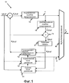
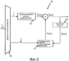
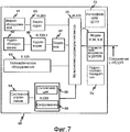
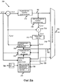
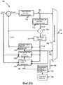
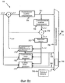
Условная схема общей системы видеокодирования с помощью скомпенсированного предсказания движения показана на фиг. 1 и 2. Фиг. 1 иллюстрирует кодер 10, применяющий скомпенсированное предсказание движения, а фиг. 2 иллюстрирует соответствующий декодер 20. Кодер 10, показанный на фиг. 1, содержит блок 11 оценки движущегося поля, блок 12 кодирования движущегося поля, блок 13 скомпенсированного предсказания движения, блок 14 кодирования ошибки предсказания, блок 15 декодирования ошибки предсказания, мультиплексирующий блок 16, кадровую память 17 и сумматор 19. Декодер 20 содержит блок 21 скомпенсированного предсказания движения, блок 22 декодирования ошибки предсказания, демультиплексирующий блок 23 и кадровую память 24.A schematic diagram of a general video coding system using compensated motion prediction is shown in FIG. 1 and 2. FIG. 1 illustrates an
Принцип работы видеокодеров, применяющих скомпенсированное предсказание движения, состоит в том, чтобы минимизировать объем информации в кадре E n(x,y) ошибки предсказания, который является разностью между текущим кодируемым кадром I n(x,y) и предсказанным кадром P n(x,y). Кадр ошибки предсказания таким образом определяется так:The principle of operation of video encoders using compensated motion prediction is to minimize the amount of information in the prediction error frame E n ( x, y ), which is the difference between the current encoded frame I n ( x, y ) and the predicted frame P n ( x , y ). The prediction error frame is thus defined as follows:
E n(x,y) = I n(x,y) - P n(x,y). (1) E n ( x, y ) = I n ( x, y ) - P n ( x, y ). (one)
Предсказанный кадр P n(x,y) строится с помощью пиксельных значений опорного кадра R n(x,y), который в общем случае является одним из ранее кодированных и переданных кадров, например кадром, непосредственно предшествующим текущему кадру, и доступен из кадровой памяти 17 кодера 10. Конкретнее, предсказанный кадр P n(x,y) сооружается путем нахождения «предсказанных пикселов» в опорном кадре R n(x,y), которые по существу соответствуют пикселам в текущем кадре. Выделяется информация движения, описывающая соотношение (например, относительное местоположение, вращение, масштаб и т.п.) между пикселами в текущем кадре и их соответствующих предсказанных пикселах в опорном кадре, и предсказанный кадр сооружается путем перемещения предсказанных пикселов согласно информации движения. При этом предсказанный кадр сооружается в качестве приблизительного представления текущего кадра с помощью пиксельных значений в опорном кадре. Упомянутый выше кадр ошибки предсказания поэтому представляет разность между приблизительным представлением текущего кадра, предоставленным предсказанным кадром, и самим текущим кадром. Основное преимущество, обеспечиваемое видеокодерами, которые используют скомпенсированное предсказание движения, возникает из того факта, что сравнительно компактное описание текущего кадра можно получить за счет информации движения, требуемой для формирования предсказания, вместе со связанной информацией ошибки предсказания в кадре ошибки предсказания.The predicted frame P n ( x, y ) is constructed using the pixel values of the reference frame R n ( x, y ), which in the general case is one of the previously encoded and transmitted frames, for example, the frame immediately preceding the current frame and is accessible from the
Вследствие большого числа пикселов в кадре в общем случае неэффективно передавать в декодер отдельную информацию движения для каждого пиксела. Вместо этого в большинстве видеокодирующих схем текущий кадр разделяется на большое число сегментов S k, и в декодер передается информация движения, относящаяся к этим сегментам. К примеру, информация движения, как правило, обеспечивается для каждого макроблока кадра, а затем та же самая информация движения используется для всех кадров в этом макроблоке. В некоторых стандартах видеокодирования, таких как рекомендация Н.26L ITU-T, ныне находящаяся в разработке, макроблок может быть разделен на меньшие блоки, причем каждый меньший блок снабжается своей собственной информацией движения.Due to the large number of pixels in the frame, it is generally inefficient to transmit separate motion information for each pixel to the decoder. Instead, in most video coding schemes, the current frame is divided into a large number of segments S k , and motion information related to these segments is transmitted to the decoder. For example, motion information is typically provided for each macroblock of a frame, and then the same motion information is used for all frames in that macroblock. In some video coding standards, such as the H.26L ITU-T recommendation currently under development, the macroblock can be divided into smaller blocks, each smaller block being provided with its own motion information.
Информация движения обычно принимает вид векторов движения [Δx(x,y), Δy(x,y)]. Пара чисел Δx(x,y) и Δy(x,y) представляет горизонтальное и вертикальное смещение пиксела (x,y) в текущем кадре I n(x,y) по отношению к пикселу в опорном кадре R n(x,y). Векторы [Δx(x,y), Δy(x,y)] движения вычисляются в блоке 11 оценки движущегося поля, а набор векторов движения в текущем кадре [Δx(·), Δy(·)] называется полем векторов движения.The motion information usually takes the form of motion vectors [Δ x ( x, y ), Δ y ( x, y )]. The pair of numbers Δ x ( x, y ) and Δ y ( x, y ) represents the horizontal and vertical displacement of the pixel ( x, y ) in the current frame I n ( x, y ) with respect to the pixel in the reference frame R n ( x, y ). The motion vectors [Δ x ( x, y ), Δ y ( x, y )] are calculated in the moving
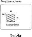
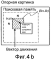
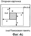
Как правило, местоположение макроблока в текущем видеокадре конкретизируется координатами (x,y) его верхнего левого угла. Тем самым в схеме видеокодирования, в которой информация движения связывается с каждым макроблоком в кадре, каждый вектор движения описывает горизонтальное и вертикальное смещение Δx(x,y) и Δy(x,y) пиксела, представляющего верхний левый угол макроблока в текущем кадре I n(x,y) по отношению к пикселу в верхнем левом углу практически соответствующего блока предсказанных пикселов в опорном кадре R n(x,y) (как показано на фиг. 4b).As a rule, the location of the macroblock in the current video frame is specified by the coordinates ( x, y ) of its upper left corner. Thus, in a video coding scheme in which motion information is associated with each macroblock in a frame, each motion vector describes the horizontal and vertical displacement Δ x ( x, y ) and Δ y ( x, y ) of a pixel representing the upper left corner of the macroblock in the current frame I n ( x, y ) with respect to the pixel in the upper left corner of the practically corresponding block of predicted pixels in the reference frame R n ( x, y ) (as shown in Fig. 4b).
Оценка движения представляет собой напряженную в вычислительном отношении задачу. При заданном опорном кадре R n(x,y) и, к примеру, квадратном макроблоке N×N пикселов в текущем кадре (как показано на фиг. 4а) цель оценки движения состоит в нахождении в опорном кадре пиксельного блока N×N, который согласуется с характеристиками макроблока в текущей картинке согласно некоторому критерию. Этим критерием может быть, например, сумма абсолютных разностей (САР) (SAD) между пикселами макроблока в текущем кадре и блока пикселов в опорном кадре, с которым он сравнивается. Этот способ известен в общем как «сопряжение блоков». Следует отметить, что в общем случае должна согласовываться геометрия блока и что опорный кадр не обязан быть одним и тем же, когда объекты реального мира могут подвергаться изменениям масштаба, а также вращению и деформации. Однако в нынешних международных стандартах видеокодирования, таких как указанные выше, используется лишь модель поступательного движения (см. ниже), а потому достаточно фиксированной прямоугольной геометрии.Motion estimation is a computationally intensive task. Given a reference frame R n ( x, y ) and, for example, a square macroblock of N × N pixels in the current frame (as shown in Fig. 4a), the purpose of the motion estimation is to find an N × N pixel block in the reference frame that is consistent with macroblock characteristics in the current picture according to some criterion. This criterion may be, for example, the sum of the absolute differences (CAP) (SAD) between the pixels of the macroblock in the current frame and the block of pixels in the reference frame with which it is compared. This method is generally known as “block pairing”. It should be noted that in the general case, the geometry of the block should be consistent and that the reference frame does not have to be the same when real-world objects can undergo scale changes, as well as rotation and deformation. However, in the current international video coding standards, such as those mentioned above, only the translational motion model is used (see below), and therefore a fairly fixed rectangular geometry is used.
В идеале, для того чтобы достичь наилучшей возможности найти сопряжение, следует просмотреть весь опорный кадр. Однако это непрактично, т.к. накладывает слишком тяжелое бремя вычислений на видеокодер. Вместо этого область поиска обычно ограничивается до области [-p,p] вокруг исходного местоположения макроблока в текущем кадре, как показано на фиг. 4с.Ideally, in order to achieve the best possible match, you should view the entire reference frame. However, this is impractical because imposes too heavy a burden of computation on the video encoder. Instead, the search region is usually limited to the region [- p, p ] around the original macroblock location in the current frame, as shown in FIG. 4s
Чтобы снизить объем информации движения, подлежащей передаче от кодера 10 к декодеру 20, поле векторов движения кодируется в блоке 12 кодирования поля движения в кодере 10 путем представления его моделью движения. В этом способе векторы движения сегментов изображения получают иное выражение с помощью некоторых заданных функций или, иными словами, поле векторов движения представляют моделью. Почти все ныне используемые модели поля векторов движения являются аддитивными моделями движения, удовлетворяющими следующим общим формулам:In order to reduce the amount of motion information to be transmitted from the
![]()
![]()
![]()
![]()
где a i и b i являются коэффициентами движения. Эти коэффициенты движения передаются к декодеру 20 (информационный поток 2 на фиг. 1 и 2). Функции f i и g i представляют собой базисные функции поля движения. Они известны как кодеру, так и декодеру. Приблизительное поле ![]()
![]()
Простейшей моделью движения является модель поступательного движения, которая требует лишь двух коэффициентов для описания векторов движения каждого сегмента. Величины векторов движения задаются уравнениямиThe simplest motion model is the translational motion model, which requires only two coefficients to describe the motion vectors of each segment. The magnitudes of the motion vectors are given by the equations
Δx(x,y) = a 0 Δ x ( x, y ) = a 0
Δy(x,y) = b 0 (4)Δ y ( x, y ) = b 0 (4)
Это модель, использованная в рекомендациях Н.263 ITU-T и стандартах ISO MPEG-1, MPEG-2, MPEG-4, чтобы описать движение пиксельных блоков 16×16 и 8×8. Системы, которые используют модель поступательного движения, как правило, выполняют оценку движения в полнопиксельном разрешении или некоторой целой части полнопиксельного разрешения, например, в полу- или четвертьпиксельном разрешении.This is the model used in the H.263 ITU-T recommendations and ISO MPEG-1, MPEG-2, MPEG-4 standards to describe the movement of pixel blocks 16 × 16 and 8 × 8. Systems that use the translational motion model typically perform motion estimation in full-pixel resolution or some integer part of full-pixel resolution, for example, in half- or quarter-pixel resolution.
Предсказанный кадр P n(x,y) строится в блоке 13 скомпенсированного предсказания движения в кодере 10 и задается уравнениемThe predicted frame P n ( x, y ) is constructed in
![]()
![]()
В блоке 14 кодирования ошибки предсказания кадр E n(x,y) обычно сжимается путем представления его в качестве конечного ряда (преобразования) некоторых двумерных функций. К примеру, можно использовать двумерное дискретное косинусное преобразование (ДКП) (DCT). Коэффициенты преобразования квантуются и подвергаются энтропийному кодированию (например, по Хаффману) перед тем, как они передаются к декодеру (информационный поток 1 на фиг. 1 и 2). Вследствие того что квантование вносит ошибку, эта операция обычно приводит к некоторому ухудшению (потере информации) в кадре E n(x,y) ошибки предсказания. Чтобы скомпенсировать это ухудшение, кодер 10 также содержит блок 15 декодирования ошибки предсказания, где с помощью коэффициентов преобразования строится декодированный кадр ![]()
![]()
![]()
![]()
Информационный поток 2, несущий информацию о векторах движения, объединяется в мультиплексоре 16 с информацией об ошибке предсказания, и информационный поток 3, содержащий, как правило, по меньшей мере два типа информации, посылается к декодеру 20.The
Теперь будет описана работа соответствующего видеодекодера 20.Now will be described the operation of the
Кадровая память 24 декодера 20 хранит ранее восстановленный опорный кадр R n(x,y). Предсказанный кадр P n(x,y) строится в блоке 21 скомпенсированного предсказания движения в декодере 20 согласно уравнению (5) с помощью принятой информации о коэффициентах движения и значениях пикселов ранее построенного опорного кадра R n(x,y). Переданные коэффициенты преобразования кадра E n(x,y) используются в блоке 22 декодирования ошибки предсказания для построения декодированного кадра ![]()
![]()
![]()
![]()
![]()
![]()
![]()
![]()
Этот декодированный текущий кадр может сохраняться в кадровой памяти 24 в качестве следующего опорного кадра R n+1(x,y).This decoded current frame may be stored in
В представленном выше описании кодирования и декодирования скомпенсированного движения в цифровом видео вектор [Δx(x,y), Δy(x,y)] движения, описывающий движение макроблока в текущем кадре по отношению к опорному кадру R n(x,y), может указывать на любые из пикселов в опорном кадре. Это означает, что движение между кадрами цифровой видеопоследовательности может быть представлено только при разрешении, определяемом пикселами изображения в кадре (так называемое полнопиксельное разрешение). Реальное же движение имеет произвольную точность, а потому описанная выше система может обеспечить лишь приблизительное моделирование движения между следующими друг за другом кадрами цифровой видеопоследовательности. Как правило, моделирование движения между видеокадрами с полнопиксельным разрешением не бывает достаточно точным, чтобы обеспечить эффективную минимизацию ошибки предсказания (ОП) (РЕ), связанной с каждым макроблоком или кадром. Поэтому, чтобы обеспечить более точное моделирование реального движения и помочь в снижении объема информации ОП, который должен быть передан от кодера к декодеру, многие стандарты видеокодирования позволяют векторам движения указывать на «промежуточные» пикселы изображения. Другими словами, векторы движения могут иметь «субпиксельное» разрешение. Позволение векторам движения иметь субпиксельное разрешение добавляется к сложности операций кодирования и декодирования, которые надлежит выполнять, так что еще более выгодно ограничить степень пространственного разрешения, которую может иметь вектор движения. Таким образом, стандарты видеокодирования, такие как упоминавшиеся ранее, обычно позволяют векторам движения иметь полнопиксельное, полупиксельное и четвертьпиксельное разрешение.In the above description of the coding and decoding of compensated motion in digital video, the motion vector [Δ x ( x, y ), Δ y ( x, y )] describing the movement of the macroblock in the current frame with respect to the reference frame R n ( x, y ) , can point to any of the pixels in the reference frame. This means that the movement between frames of a digital video sequence can be represented only at a resolution determined by the image pixels in the frame (the so-called full-pixel resolution). The real movement has arbitrary accuracy, and therefore the system described above can provide only an approximate simulation of the movement between successive frames of a digital video sequence. As a rule, motion simulation between full-resolution video frames is not accurate enough to effectively minimize the prediction error (OD) (PE) associated with each macroblock or frame. Therefore, in order to provide more accurate modeling of real motion and to help reduce the amount of OP information that must be transmitted from the encoder to the decoder, many video coding standards allow motion vectors to point to “intermediate” image pixels. In other words, motion vectors can have a “sub-pixel” resolution. Allowing motion vectors to have sub-pixel resolution is added to the complexity of the encoding and decoding operations to be performed, so it is even more beneficial to limit the degree of spatial resolution that a motion vector can have. Thus, video coding standards, such as those mentioned earlier, usually allow motion vectors to have full-pixel, half-pixel, and quarter-pixel resolutions.
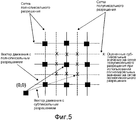
Оценка движения с субпиксельным разрешением может быть воплощена как двухстадийный процесс, как иллюстрируется в примерном виде на фиг. 5, для основной схемы видеокодирования, в которой векторы движения могут иметь полно- или полупиксельное разрешение. На первой стадии вектор движения, имеющий полнопиксельное разрешение, находят с помощью подходящей схемы оценки движения, такой как описанный выше способ сопряжения блоков. На фиг. 5 показан результирующий вектор движения, имеющий полнопиксельное разрешение.Subpixel resolution motion estimation can be implemented as a two-stage process, as illustrated in an exemplary form in FIG. 5 for a basic video coding scheme in which motion vectors can have full or half pixel resolution. In a first step, a motion vector having full pixel resolution is found using a suitable motion estimation scheme, such as the block pairing method described above. In FIG. 5 shows the resulting motion vector having full-pixel resolution.
На второй стадии вектор движения, найденный на первой стадии, улучшается, чтобы получить желательное полупиксельное разрешение. В примере, проиллюстрированном на фиг. 5, это делается путем формирования восьми новых поисковых блоков из 16×16 пикселов, причем местоположение верхнего левого угла каждого блока помечено позицией Х на фиг. 5. Эти местоположения обозначаются как [Δx + m/2, Δy + n/2], где m и n могут принимать значения -1, 0 и +1, но не могут быть нулем в одно и то же время. Поскольку известны только значения пикселов для пикселов исходного изображения, значения (к примеру, значения яркости и/или цветности) субпикселов, находящихся в полупиксельных местоположениях, оцениваются для каждого из восьми новых поисковых блоков с помощью какого-либо вида интерполяционной схемы.In the second stage, the motion vector found in the first stage is improved to obtain the desired half-pixel resolution. In the example illustrated in FIG. 5, this is done by forming eight new search blocks of 16 × 16 pixels, wherein the location of the upper left corner of each block is indicated by X in FIG. 5. These locations are denoted as [Δ x + m / 2, Δ y + n / 2], where m and n can take values -1, 0 and +1, but cannot be zero at the same time. Since only pixel values for pixels of the original image are known, values (for example, brightness and / or color values) of subpixels located at half-pixel locations are estimated for each of the eight new search units using some kind of interpolation scheme.
Интерполируя значения субпикселов с полупиксельным разрешением, каждый из восьми поисковых блоков сравнивается с макроблоков, чей вектор движения ищется. Как и в способе сопряжения блоков, выполняемом для нахождения вектора движения с полнопиксельным разрешением, макроблок сравнивается с каждым из восьми поисковых блоков согласно некоторому критерию, к примеру, САР. В результате сравнения в общем случае будет получено минимальное значение САР. В зависимости от природы движения в видеопоследовательности это минимальное значение может соответствовать местоположению, определенному исходным вектором движения (с полнопиксельным разрешением) или оно может соответствовать местоположению с полупиксельным разрешением. Таким образом, возможно определить, указывает ли вектор движения на полнопиксельное или полупиксельное местоположение, и, если приемлемо полупиксельное разрешение, найти правильный вектор движения с полупиксельным разрешением.Interpolating the values of subpixels with half-pixel resolution, each of the eight search blocks is compared with the macroblocks whose motion vector is sought. As in the method of pairing blocks performed to find the motion vector with full pixel resolution, the macroblock is compared with each of the eight search blocks according to some criterion, for example, CAP. As a result of the comparison, in the general case, the minimum ATS value will be obtained. Depending on the nature of the motion in the video sequence, this minimum value may correspond to the location determined by the original motion vector (with full pixel resolution) or it may correspond to the location with half pixel resolution. Thus, it is possible to determine whether the motion vector indicates a full-pixel or half-pixel location, and if half-pixel resolution is acceptable, find the correct motion vector with half-pixel resolution.
На практике оценка субпиксельного значения в опорном кадре выполняется путем интерполирования значения субпиксела из окружающих пиксельных значений. В общем случае, интерполяция значения F(x,y), расположенного в нецелом местоположении (x,y) = (n+Δx, m+Δy), может формулироваться как двумерная операция, математически представленная какIn practice, estimation of a subpixel value in a reference frame is performed by interpolating a subpixel value from surrounding pixel values. In general, the interpolation of the value of F (x, y) located at a non-integral location (x, y) = (n + Δx, m + Δy) can be formulated as a two-dimensional operation, mathematically represented as
![]()
![]()
где f(k,l) представляют собой коэффициенты фильтров, а n и m получаются усечением соответственно x и y до целых величин. Как правило, коэффициенты фильтров зависят от значений x и y, а интерполяционные фильтры обычно именуют «разделяемыми фильтрами», и в этом случае субпиксельное значение F(x,y) можно вычислить следующим образом:where f (k, l) are the filter coefficients, and n and m are obtained by truncating x and y, respectively, to integer values. As a rule, filter coefficients depend on x and y values , and interpolation filters are usually referred to as “shared filters”, in which case the sub-pixel value F (x, y) can be calculated as follows:
![]()
![]()
Векторы движения вычисляются в кодере. Когда соответствующие коэффициенты движения передаются в декодер, то интерполировать требуемые субпикселы с помощью интерполяционного способа, идентичного использованному в кодере, представляется простым делом. При этом кадр, следующий за опорным кадром в кадровой памяти 24, может быть восстановлен из опорного кадра и переданных векторов движения.Motion vectors are calculated in the encoder. When the corresponding motion coefficients are transmitted to the decoder, then interpolating the required subpixels using an interpolation method identical to that used in the encoder seems to be a simple matter. In this case, the frame following the reference frame in the
Традиционно, интерполяционные фильтры, используемые в видеокодерах и видеодекодерах, применяют фиксированные значения коэффициентов фильтров, и один и тот же фильтр (т.е. один и тот же тип фильтра с теми же самыми значениями коэффициентов фильтра) используется для всех кадров кодируемой видеопоследовательности. Тот же самым фильтр используется далее для всех видеопоследовательностей, безотносительно к их природе и к тому, как они были собраны (захвачены). Wedi ("Adaptive Interpolation Filter for Motion Compensated Hybrid Video Coding", Picture Coding Symposium (PCS 2001) [«Адаптивный интерполяционный фильтр для гибридного видеокодирования скомпенсированного движения», Симпозиум по кодированию изображений], Сеул, Корея, Апрель 2001) предлагает использование интерполяционных фильтров с адаптивными значениями коэффициентов фильтра, чтобы скомпенсировать некоторые недостатки в способе видеокодирования. В частности, Wedi описывает, как, при наложении в процессе получения изображений, конечное разрешение дозволенных векторов движения и ограничение правильности модели поступательного движения вносят дополнительные ошибки предсказания. Наложение в видеоизображениях возникает вследствие использования неидеальных фильтров нижних частот (и, как следствие, невыполнение теоремы отсчетов Найквиста) в процессе получения изображения. Наложение нарушает скомпенсированное предсказание движения в видеопоследовательности и вызывает дополнительную компоненту ошибки предсказания. Конечная точность дозволенных векторов движения (например, полнопиксельная, полупиксельная или четвертьпиксельная) и способность модели поступательного движения представлять лишь горизонтальное и вертикальное поступательное движение между следующими друг за другом видеокадрами также вызывают дополнительные составляющие ошибки предсказания. Wedi предполагает далее, что улучшения в эффективности кодирования можно достичь путем адаптации значений коэффициентов фильтра в интерполяционном фильтре, чтобы компенсировать дополнительные ошибки предсказания, внесенные наложением, конечную точность вектора движения и ограниченную правильность модели поступательного движения.Traditionally, interpolation filters used in video encoders and video decoders apply fixed filter coefficient values, and the same filter (i.e. the same filter type with the same filter coefficient values) is used for all frames of the encoded video sequence. The same filter is used further for all video sequences, regardless of their nature and how they were assembled (captured). Wedi ("Adaptive Interpolation Filter for Motion Compensated Hybrid Video Coding", Picture Coding Symposium (PCS 2001) [Adaptive Interpolation Filter for Hybrid Video Coding for Compensated Motion, Symposium on Image Coding], Seoul, Korea, April 2001) proposes the use of interpolation filters with adaptive filter coefficient values to compensate for some of the shortcomings in the video coding method. In particular, Wedi describes how, when superimposed during image acquisition, the final resolution of the allowed motion vectors and the limitation of the correctness of the translational motion model introduce additional prediction errors. Overlapping in video images occurs due to the use of non-ideal low-pass filters (and, as a result, the failure of the Nyquist sampling theorem) in the process of image acquisition. The overlay violates the compensated motion prediction in the video sequence and causes an additional component of the prediction error. The finite accuracy of the allowed motion vectors (e.g., full-pixel, half-pixel, or quarter-pixel) and the ability of the translational motion model to represent only horizontal and vertical translational motion between successive video frames also cause additional prediction error components. Wedi further suggests that improvements in coding efficiency can be achieved by adapting the filter coefficients in the interpolation filter to compensate for the additional prediction errors introduced by the overlay, the finite accuracy of the motion vector, and the limited correctness of the translational motion model.
В более общем случае, следует понимать, что, поскольку природа и характеристики движения изменяются в видеопоследовательности, оптимальный интерполяционный фильтр изменяется как функция от времени и местоположения в изображении. Wedi представляет пример, в котором интерполяционный фильтр с динамически адаптивными значениями коэффициентов фильтра встраивается в видеокодек H.26L, конкретнее в версию этого кодека, определенную тестовой моделью (TML) 4. TML-4 в H.26L использовала четвертьпиксельное разрешение вектора движения и интерполяционный фильтр винеровского типа с шестью симметричными коэффициентами фильтра (6-отводный фильтр). Представленный в статье Wedi пример предлагает адаптацию коэффициентов фильтра в интерполяционном фильтре на покадровой основе, дифференциальное кодирование коэффициентов фильтра и передачу их к декодеру в качестве побочной информации к основным видеоданным. Было сделано предложение на основе этого подхода включить использование интерполяционных фильтров с динамически адаптивными значениями коэффициентов фильтра в тестовой модели 8 видео кодека H.26L. Это представлено в документе сектора стандартизации связи ITU, озаглавленном "Adaptive Interpolation Filter for H.26L" (Адаптивный интерполяционный фильтр для H.26L) Study Group 16, Question 6, Video Coding Experts Group (VCEG), document VCEG-N28 September 2001, и "More Results on Adaptive Interpolation Filter for H.26L" (Больше результатов по Адаптивному интерполяционному фильтру для H.26L) Study Group 16, Question 6, Video Coding Experts Group (VCEG), document VCEG-O16r1, November 2001.In a more general case, it should be understood that, since the nature and characteristics of the movement change in the video sequence, the optimal interpolation filter changes as a function of time and location in the image. Wedi presents an example in which an interpolation filter with dynamically adaptive filter coefficients is embedded in the H.26L video codec, more specifically in the version of this codec defined by the test model (TML) 4. TML-4 in H.26L used a quarter-pixel resolution of the motion vector and an interpolation filter Wiener type with six symmetric filter coefficients (6-tap filter). The example presented in the Wedi article offers the adaptation of filter coefficients in an interpolation filter on a frame-by-frame basis, differential coding of filter coefficients and their transmission to the decoder as secondary information to the main video data. A proposal was made based on this approach to include the use of interpolation filters with dynamically adaptive filter coefficients in test model 8 of the H.26L video codec. This is presented in an ITU communications standardization sector document entitled “Adaptive Interpolation Filter for H.26L”
Использование динамически адаптивных интерполяционных фильтров вызывает важный вопрос, касающийся эффективности кодирования закодированного потока видеоданных, а также воздействует на стойкость к ошибкам кодированных видеоданных. Вопрос эффективности кодирования можно легко понять. В видеокодирующей системе, которая применяет интерполирующий фильтр с фиксированными значениями коэффициентов фильтра, нет необходимости включать какую-либо информацию, относящуюся к значениям коэффициентов фильтра в битовом потоке кодированных видеоданных. Значения коэффициентов фильтра могут просто записываться в видеокодере и видеодекодере. Иными словами, в видеокодирующей системе, воплощенной согласно конкретному стандарту видеокодирования, который применяет фиксированные интерполяционные фильтры, значения коэффициентов заранее запрограммированы как в кодере, так и в декодере согласно описаниям стандарта. Однако, если допускаются динамически адаптивные коэффициенты фильтра, становится необходимым передавать информацию, связанную со значениями коэффициентов. По мере периодического обновления коэффициентов фильтра (например, на покадровой основе) эта информация с необходимостью добавляется к объему информации, подлежащей передаче от видеокодера к видеодекодеру, и имеет вредное влияние на эффективность кодирования. В применениях видеокодирования с низкой битовой скоростью любое увеличение в объеме информации, подлежащей передаче, в большинстве случаев нежелательно.The use of dynamically adaptive interpolation filters raises an important question regarding the encoding efficiency of the encoded video data stream, and also affects the error resistance of encoded video data. The issue of coding efficiency can be easily understood. In a video coding system that uses an interpolating filter with fixed filter coefficient values, there is no need to include any information related to the filter coefficient values in the bitstream of the encoded video data. The filter coefficients can simply be recorded in the video encoder and video decoder. In other words, in a video coding system implemented according to a specific video coding standard that uses fixed interpolation filters, the coefficient values are pre-programmed both in the encoder and in the decoder according to the standard descriptions. However, if dynamically adaptive filter coefficients are allowed, it becomes necessary to transmit information related to the coefficient values. As the filter coefficients are periodically updated (for example, on a frame-by-frame basis), this information is necessarily added to the amount of information to be transmitted from the video encoder to the video decoder, and has a detrimental effect on the coding efficiency. In low bit rate video coding applications, any increase in the amount of information to be transmitted is in most cases undesirable.
Таким образом, для того чтобы оптимально моделировать и компенсировать движение, нужно эффективное представление динамических интерполяционных фильтров.Thus, in order to optimally simulate and compensate for motion, an effective representation of dynamic interpolation filters is needed.
Что касается стойкости к ошибкам, то следует понимать, что путь, которым информация о коэффициентах динамически переменного интерполяционного фильтра передается от кодера к декодеру, может влиять на восприимчивость видеоданных к ошибкам передачи. Конкретнее, в видеокодирующих системах, которые применяют динамически адаптивные интерполяционные фильтры, правильное восстановление кадра в видеопоследовательности на декодере зависит от правильного приема и декодирования значений коэффициентов фильтра. Если информация, относящаяся к значениям коэффициентов, подвергается ошибкам во время ее передачи от кодера к декодеру, вероятно искажение восстанавливаемых видеоданных. Существует три известных в уровне техники пути кодирования коэффициентов фильтра. Первый состоит в энтропийном кодировании по отдельности значений коэффициентов фильтра. Второй состоит в энтропийном кодировании значений коэффициентов фильтра дифференцированно, по отношению к коэффициентам фильтра уже декодированных фильтров (как предложено в статье Wedi), а третий представляет собой определение набора фильтров и кодирование индекса выбранного фильтра.With regard to error resistance, it should be understood that the way in which information about the coefficients of a dynamically variable interpolation filter is transmitted from the encoder to the decoder can affect the susceptibility of video data to transmission errors. More specifically, in video coding systems that employ dynamically adaptive interpolation filters, the correct reconstruction of a frame in a video sequence at a decoder depends on the correct reception and decoding of filter coefficient values. If the information related to the coefficient values is subject to errors during its transmission from the encoder to the decoder, distortion of the restored video data is likely. There are three prior art coding methods for filter coefficients. The first is entropy coding of filter coefficient values separately. The second consists in entropy coding of the filter coefficient values differentially, with respect to the filter coefficients of the filters already decoded (as suggested by Wedi ), and the third is the definition of the filter set and the coding of the index of the selected filter.
Известные в уровне техники решения, которые можно было бы использовать для кодирования коэффициентов интерполяционного фильтра, как упомянуто выше, все имеют проблемы, связанные с ними в различных сценариях использования. Первый способ, в котором коэффициенты интерполяционного фильтра кодируются по отдельности, предлагают более низкую производительность кодирования, т.к. он не использует никакой предварительной информации (т.е. информации о точно закодированных значениях коэффициентов интерполяционного фильтра). Этот подход, следовательно, требует чрезмерно большого объема информации, подлежащей добавлению к закодированным к потоку кодированных видеобитов для того, чтобы описать значения коэффициентов интерполяционного фильтра. Дифференциальное кодирование коэффициентов, как предлагается в статье Wedi, эффективно, но не может использоваться в среде с возможными ошибками передачи, поскольку коэффициенты фильтра зависят от правильного декодирования более ранних коэффициентов фильтра. Как описано ранее, если битовый поток кодированных данных подвергается воздействию ошибки во время его передачи от кодера к декодеру, вероятно возникновение искажения видеоданных, восстановленных в декодере. Третье известное из уровня техники решение с заданным набором фильтров обеспечивает только ограниченные альтернативы и тем самым ухудшает производительность кодирования. Иными словами, эта опция не может достичь полных преимуществ от использования интерполяционных фильтров с динамически адаптивными значениями коэффициентов фильтра, как излагается в статье Wedi.The prior art solutions that could be used to encode the coefficients of an interpolation filter, as mentioned above, all have problems associated with them in various use cases. The first method, in which the coefficients of the interpolation filter are encoded separately, offer lower coding performance because it does not use any preliminary information (i.e., information on precisely encoded values of the coefficients of the interpolation filter). This approach, therefore, requires an excessively large amount of information to be added to the encoded stream of encoded video bits in order to describe the values of the coefficients of the interpolation filter. Differential coefficient coding, as suggested by Wedi , is effective, but cannot be used in environments with possible transmission errors, since filter coefficients depend on the correct decoding of earlier filter coefficients. As described previously, if the bitstream of the encoded data is subjected to an error during its transmission from the encoder to the decoder, distortion of the video data restored in the decoder is likely to occur. A third prior art solution with a predetermined set of filters provides only limited alternatives and thereby degrades coding performance. In other words, this option cannot achieve the full benefits of using interpolation filters with dynamically adaptive filter coefficients, as described in Wedi .
Таким образом, должно быть понятно, что имеется необходимость в способе кодирования значений коэффициентов адаптивных интерполяционных фильтров, который был бы эффективен и не приводил к ухудшению в стойкости к ошибкам битового потока кодированных данных.Thus, it should be understood that there is a need for a method of coding the coefficient values of adaptive interpolation filters that is efficient and does not lead to a deterioration in error resistance of the bitstream of the encoded data.
Сущность изобретенияSUMMARY OF THE INVENTION
Настоящее изобретение объединяет хорошую эффективность кодирования от дифференциального кодирования со свойствами стойкости к ошибкам, что позволяет использовать его во всех средах. Поэтому оно, в частности, пригодно для осуществления в видеокодирующей системе для использования в подверженных ошибкам средах, например, когда поток кодированных видеобитов должен передаваться по линии радиосвязи, подверженной помехам.The present invention combines good coding efficiency from differential coding with error resistance properties, which allows it to be used in all environments. Therefore, it is, in particular, suitable for implementation in a video coding system for use in error prone environments, for example, when a stream of encoded video bits must be transmitted over a radio communication line subject to interference.
Таким образом, согласно первому аспекту настоящего изобретения предлагается способ кодирования изображений в цифровой видеопоследовательности для получения кодированных видеоданных, причем цифровая видеопоследовательность содержит последовательность видеокадров, а каждый видеокадр имеет множество пиксельных значений, и при этом для восстановления пиксельных значений в кадре упомянутой цифровой видеопоследовательности из кодированных видеоданных используют интерполяционный фильтр, имеющий множество коэффициентов, представленных множеством значений коэффициентов.Thus, according to a first aspect of the present invention, there is provided a method of encoding images in a digital video sequence to obtain encoded video data, wherein the digital video sequence contains a sequence of video frames and each video frame has a plurality of pixel values, and wherein, to recover pixel values in a frame of said digital video sequence from encoded video data using an interpolation filter having multiple coefficients is represented many set of coefficients.
Способ отличается тем, чтоThe method is characterized in that
кодируют значения коэффициентов интерполяционного фильтра дифференциально по отношению к заданному базовому фильтру, чтобы сформировать набор разностных значений, иencode the values of the coefficients of the interpolation filter differentially with respect to a given base filter to form a set of difference values, and
адаптируют набор разностных значений в кодированных видеоданных таким образом, чтобы восстановление пиксельных значений было основано на наборе разностных значений.adapt the set of difference values in the encoded video data so that the recovery of pixel values is based on a set of difference values.
Преимущественно кодированные видеоданные включают в себя кодированные значения, выражающие упомянутый набор разностных значений, а набор разностных значений энтропийно кодируют перед передачей от видеокодера к видеодекодеру.Advantageously, encoded video data includes encoded values expressing said set of difference values, and a set of difference values are entropy encoded before being transmitted from the video encoder to the video decoder.
Преимущественно заданный базовый фильтр имеет множество коэффициентов со значениями, статистически аналогичными значениям коэффициентов интерполяционного фильтра.Advantageously, the predetermined base filter has a plurality of coefficients with values statistically similar to the values of the coefficients of the interpolation filter.
Преимущественно коэффициенты интерполяционного фильтра выбирают для интерполяции пиксельных значений в выбранном сегменте изображения.Advantageously, the interpolation filter coefficients are selected to interpolate pixel values in the selected image segment.
Преимущественно заданный базовый фильтр имеет фиксированные значения коэффициентов.Advantageously, the predetermined base filter has fixed coefficient values.
Преимущественно заданный базовый фильтр имеет множество коэффициентов, адаптированных к статистическим данным видеопоследовательности.A predominantly defined base filter has a plurality of coefficients adapted to the statistics of the video sequence.
Предпочтительно интерполяционный фильтр является симметричным, так что кодируют только половину коэффициентов фильтра.Preferably, the interpolation filter is symmetric, so that only half of the filter coefficients are encoded.
Преимущественно значения коэффициентов интерполяционного фильтра кодируют в определенном порядке от первого значения коэффициента к последнему значению коэффициента, и этот определенный порядок отличается от пространственного порядка упомянутых коэффициентов.Advantageously, the coefficient values of the interpolation filter are encoded in a specific order from the first coefficient value to the last coefficient value, and this specific order differs from the spatial order of the mentioned coefficients.
Преимущественно сумма значений коэффициентов интерполяционного фильтра фиксирована.Mostly the sum of the values of the coefficients of the interpolation filter is fixed.
Преимущественно заданный базовый фильтр имеет множество значений коэффициентов, и постоянное значение добавляют к этим значениям коэффициентов заданного базового фильтра, так чтобы снизить амплитуду разностей между значениями коэффициентов интерполяционного фильтра и значениями коэффициентов заданного базового фильтра.Advantageously, the predetermined base filter has a plurality of coefficient values, and a constant value is added to these coefficient values of the predetermined base filter, so as to reduce the amplitude of the differences between the interpolation filter coefficients and the coefficients of the given base filter.
Согласно второму аспекту настоящего изобретения предлагается видеокодер, который содержитAccording to a second aspect of the present invention, there is provided a video encoder that comprises
средство для кодирования изображений в цифровой видеопоследовательности, имеющей последовательность видеокадров, для получения кодированных видеоданных, выражающих эту видеопоследовательность, а каждый кадр видеопоследовательности содержит множество пиксельных значений, иmeans for encoding images in a digital video sequence having a sequence of video frames to obtain encoded video data expressing the video sequence, and each frame of the video sequence contains a plurality of pixel values, and
средство для определения интерполяционного фильтра для восстановления пиксельных значений в кадре упомянутой цифровой видеопоследовательности в процессе декодирования, причем интерполяционный фильтр имеет несколько коэффициентов, представленных множеством значений коэффициентов.means for determining an interpolation filter for recovering pixel values in a frame of said digital video sequence in a decoding process, the interpolation filter having several coefficients represented by a plurality of coefficient values.
Видеокодер отличается тем, что содержитThe video encoder is characterized in that it contains
средство, откликающееся на интерполяционный фильтр, для вычисления разности между значениями коэффициентов интерполяционного фильтра и заданного базового фильтра для получения набора разностных значений, иmeans responsive to the interpolation filter, for calculating the difference between the values of the coefficients of the interpolation filter and the specified base filter to obtain a set of difference values, and
средство для адаптации набора разностных значений в кодированных видеоданных, предназначенное для того, чтобы восстановление пиксельных значений в процессе декодирования было основано на наборе разностных значений.means for adapting a set of difference values in encoded video data, designed to restore pixel values in a decoding process based on a set of difference values.
Преимущественно кодер содержит средство для энтропийного кодирования набора разностных значений перед адаптацией набора разностных значений в кодированных видеоданных.Advantageously, the encoder comprises means for entropy encoding a set of difference values before adapting a set of difference values in encoded video data.
Согласно третьему аспекту настоящего изобретения предлагается способ декодирования видеоданных, выражающих цифровую видеопоследовательность, содержащую последовательность видеокадров, причем каждый кадр видеопоследовательности содержит множество пиксельных значений, при этом интерполяционный фильтр, имеющий множество коэффициентов, представленных множеством значений коэффициентов, используют для восстановления пиксельных значений в кадре упомянутой цифровой видеопоследовательности.According to a third aspect of the present invention, there is provided a method for decoding video data expressing a digital video sequence comprising a sequence of video frames, wherein each frame of the video sequence contains a plurality of pixel values, wherein an interpolation filter having a plurality of coefficients represented by a plurality of coefficient values is used to reconstruct the pixel values in the frame of said digital video sequences.
Способ отличается тем, чтоThe method is characterized in that
извлекают из видеоданных набор разностных значений, причем набор разностных значений выражает разность между значениями коэффициентов интерполяционного фильтра и заданного базового фильтра,extracting from the video data a set of difference values, the set of difference values expressing the difference between the values of the coefficients of the interpolation filter and the specified base filter,
создают дополнительный фильтр на основании набора разностных значений и заданного базового фильтра, иcreate an additional filter based on a set of difference values and a given base filter, and
восстанавливают пиксельные значения на основании дополнительного фильтра.restore pixel values based on an additional filter.
Преимущественно заданный базовый фильтр имеет множество коэффициентов, представленных множеством значений коэффициентов, а создание дополнительного фильтра выполняют суммированием набора разностных значений с упомянутыми значениями коэффициентов заданного базового фильтра.Advantageously, a predetermined base filter has a plurality of coefficients represented by a plurality of coefficient values, and the creation of an additional filter is performed by summing a set of difference values with the mentioned coefficient values of a given base filter.
Преимущественно набор разностных значений извлекают из видеоданных путем энтропийного декодирования.Advantageously, the set of difference values is extracted from the video data by entropy decoding.
Согласно четвертому аспекту настоящего изобретения предлагается видеодекодер, который содержит средство для приема видеоданных в битовом потоке, причем принятые видеоданные выражают цифровую видеопоследовательность, содержащую последовательность видеокадров, а каждый кадр видеопоследовательности содержит множество пиксельных значений.According to a fourth aspect of the present invention, there is provided a video decoder which comprises means for receiving video data in a bit stream, the received video data expressing a digital video sequence comprising a sequence of video frames, and each frame of the video sequence containing a plurality of pixel values.
Видеодекодер отличается тем, что содержитThe video decoder is characterized in that it contains
средство для извлечения набора разностных значений из битового потока,means for extracting a set of difference values from the bitstream,
средство для создания интерполяционного фильтра на основании заданного базового фильтра и набора разностных значений, иmeans for creating an interpolation filter based on a given base filter and a set of difference values, and
средство для восстановления пиксельных значений в кадре видеопоследовательности на основании интерполяционного фильтра и принятых видеоданных.means for recovering pixel values in a frame of a video sequence based on an interpolation filter and received video data.
Преимущественно видеодекодер имеет дополнительно средство для суммирования набора разностных значений со значениями дополнительных коэффициентов заданного базового фильтра для создания интерполяционного фильтра и средство для энтропийного декодирования набора разностных значений из битового потока.Advantageously, the video decoder has additional means for summing the set of difference values with the values of the additional coefficients of the given base filter for creating an interpolation filter and means for entropy decoding of the set of difference values from the bitstream.
Согласно пятому аспекту настоящего изобретения предлагается видеокодирующая система, которая содержитAccording to a fifth aspect of the present invention, there is provided a video coding system which comprises
кодер для кодирования изображений в цифровой видеопоследовательности, имеющей последовательность видеокадров, для получения кодированных видеоданных в битовом потоке, выражающем видеопоследовательность, а каждый кадр видеопоследовательности содержит множество пиксельных значений, при этом кодер имеет средство для определения интерполяционного фильтра для восстановления пиксельных значений в кадре упомянутой цифровой видеопоследовательности в процессе декодирования, а интерполяционный фильтр имеет множество коэффициентов фильтра, представленных множеством значений коэффициентов, иan encoder for encoding images in a digital video sequence having a sequence of video frames to obtain encoded video data in a bit stream expressing the video sequence, and each frame of the video sequence contains a plurality of pixel values, the encoder having means for determining an interpolation filter for recovering pixel values in the frame of the mentioned digital video sequence in the decoding process, and the interpolation filter has many filter coefficients tra represented by the set of coefficient values, and
декодер для приема кодированных видеоданных в битовом потоке для восстановления пиксельных значений в кадре видеопоследовательности в процессе декодирования.a decoder for receiving encoded video data in a bit stream to recover pixel values in a frame of a video sequence during decoding.
Видеокодирующая система отличается тем, чтоThe video coding system is characterized in that
кодер дополнительно содержитthe encoder further comprises
средство для вычисления разности между интерполяционным фильтром и заданным базовым фильтром для получения набора разностных значений, иmeans for calculating the difference between the interpolation filter and the specified base filter to obtain a set of difference values, and
средство для адаптации набора разностных значений в битовом потоке, аmeans for adapting the set of difference values in the bitstream, and
декодер содержитdecoder contains
средство для извлечения из битового потока набора разностных значений, иmeans for extracting from the bitstream a set of differential values, and
средство для создания дополнительного фильтра на основании заданного базового фильтра и извлеченного набора разностных значений таким образом, чтобы восстановление пиксельных значений в процессе декодирования было основано на дополнительном фильтре.means for creating an additional filter based on a given base filter and an extracted set of difference values so that the restoration of pixel values in the decoding process is based on an additional filter.
Эти и остальные признаки настоящего изобретения станут понятными из нижеследующего описания совместно с сопровождающими чертежами. Понятно, однако, что чертежи разработаны единственно для целей иллюстрации, а не как определение пределов изобретения.These and other features of the present invention will become apparent from the following description in conjunction with the accompanying drawings. It is understood, however, that the drawings are designed solely for the purpose of illustration, and not as a definition of the scope of the invention.
Краткое описание чертежейBrief Description of the Drawings
Фиг. 1 является блок-схемой, иллюстрирующей общий видеокодер согласно существующему уровню техники.FIG. 1 is a block diagram illustrating a common video encoder according to the prior art.
Фиг. 2 является блок-схемой, иллюстрирующей общий видеодекодер согласно существующему уровню техники.FIG. 2 is a block diagram illustrating a common video decoder according to the state of the art.
Фиг. 3 является условным представлением, иллюстрирующим типы кадров, используемых в видеокодировании.FIG. 3 is a conditional representation illustrating frame types used in video coding.
Фиг. 4а является условным представлением, иллюстрирующим макроблок в текущем кадре.FIG. 4a is a conditional representation illustrating a macroblock in a current frame.
Фиг. 4b является условным представлением, иллюстрирующим опорный кадр для сопряжения блоков.FIG. 4b is a schematic view illustrating a reference frame for pairing blocks.
Фиг. 4с является условным представлением, иллюстрирующим поисковую область вокруг исходного местоположения макроблока в текущем кадре.FIG. 4c is a schematic view illustrating a search area around a source location of a macroblock in a current frame.
Фиг. 5 является условным представлением, иллюстрирующим процесс оценки движения до субпиксельного разрешения согласно существующему уровню техники.FIG. 5 is a conditional view illustrating a process for estimating motion to sub-pixel resolution according to the state of the art.
Фиг. 6а является условным представлением, иллюстрирующим оптимальный интерполяционный фильтр.FIG. 6a is a conditional representation illustrating an optimal interpolation filter.
Фиг. 6b является условным представлением, иллюстрирующим оптимальный интерполяционный фильтр, разлагаемый на базовый фильтр и разностные коэффициенты.FIG. 6b is a conditional representation illustrating an optimal interpolation filter decomposable into a base filter and difference coefficients.
Фиг. 6с является условным представлением, иллюстрирующим разностные коэффициенты для кодирования и отправки на декодер.FIG. 6c is a conditional representation illustrating difference coefficients for encoding and sending to a decoder.
Фиг. 7 представляет собой блок-схему, иллюстрирующую терминальное устройство, содержащее оборудование видеокодирования и видеодекодирования, способное осуществлять настоящее изобретение.FIG. 7 is a block diagram illustrating a terminal device comprising video coding and video decoding equipment capable of implementing the present invention.
Фиг. 8а представляет собой блок-схему, иллюстрирующую видеокодер согласно предпочтительному варианту выполнения по настоящему изобретению.FIG. 8a is a block diagram illustrating a video encoder according to a preferred embodiment of the present invention.
Фиг. 8b представляет собой блок-схему, иллюстрирующую видеокодер согласно другому варианту выполнения по настоящему изобретению.FIG. 8b is a block diagram illustrating a video encoder according to another embodiment of the present invention.
Фиг. 8с представляет собой блок-схему, иллюстрирующую видеокодер согласно еще одному варианту выполнения по настоящему изобретению.FIG. 8c is a block diagram illustrating a video encoder according to another embodiment of the present invention.
Фиг. 9а представляет собой блок-схему, иллюстрирующую видеодекодер согласно предпочтительному варианту выполнения по настоящему изобретению.FIG. 9a is a block diagram illustrating a video decoder according to a preferred embodiment of the present invention.
Фиг. 9b представляет собой блок-схему, иллюстрирующую видеодекодер согласно другому варианту выполнения по настоящему изобретению.FIG. 9b is a block diagram illustrating a video decoder according to another embodiment of the present invention.
Фиг. 9с представляет собой блок-схему, иллюстрирующую видеодекодер согласно еще одному варианту выполнения по настоящему изобретению.FIG. 9c is a block diagram illustrating a video decoder according to another embodiment of the present invention.
Наилучший режим осуществления изобретенияBEST MODE FOR CARRYING OUT THE INVENTION
Кодер согласно настоящему изобретению кодирует коэффициенты фильтра дифференциально по отношению к заданным коэффициентам базового фильтра. Фиг. 6а-6с иллюстрируют способ согласно настоящему изобретению. Столбиковые графики, представленные на фиг. 6а, являются примерами значений коэффициентов интерполяционного фильтра, причем каждый столбик соответствует одному из коэффициентов фильтра. Высота столбика представляет соответствующее значение коэффициента, при этом выступающие над горизонтальной осью столбики представляют положительные значения коэффициентов, а выступающие под горизонтальной осью столбики представляют отрицательные значения коэффициентов. На фиг. 6а и 6b столбиковый график 110 представляет фильтр, который обнаруживается кодером как наилучшим образом пригодный для интерполяции движения выбранного сегмента, тогда как столбиковый график 140 представляет базовый фильтр. В примере, показанном на фиг. 6а, фильтр является 6-отводным симметричным фильтром, имеющим 6 коэффициентов фильтра. Вместо отправки коэффициентов фильтра самих по себе, кодируются и посылаются только разности между выбранным фильтром 110 и базовым фильтром 140. Посланные коэффициенты 120 показаны на фиг. 9с.The encoder according to the present invention encodes the filter coefficients differentially with respect to the specified base filter coefficients. FIG. 6a-6c illustrate the method according to the present invention. The bar graphs shown in FIG. 6a are examples of interpolation filter coefficient values, each bar corresponding to one of the filter coefficients. The height of the bar represents the corresponding value of the coefficient, while the columns protruding above the horizontal axis represent the positive values of the coefficients, and the columns protruding below the horizontal axis represent the negative values of the coefficients. In FIG. 6a and 6b, the
С настоящим изобретением получается выигрыш в кодировании, поскольку малые амплитудные разности можно эффективно кодировать энтропийным кодером. Когда такие разностные значения включаются в поток кодированных видеобитов, получаемый видеокодером, и этот поток видеобитов передается от кодера к соответствующему декодеру, коэффициенты интерполяционного фильтра могут восстанавливаться в декодере путем извлечения разностных значений из кодированного битового потока и добавления их к соответствующим значениям коэффициентов заданного базового фильтра, сохраненным в декодере.With the present invention, a gain in coding is obtained since small amplitude differences can be efficiently encoded by an entropy encoder. When such difference values are included in the encoded video bit stream received by the video encoder, and this video bit stream is transmitted from the encoder to the corresponding decoder, the interpolation filter coefficients can be restored in the decoder by extracting the difference values from the encoded bit stream and adding them to the corresponding coefficient values of the given base filter, saved in the decoder.
Следует отметить, что базовый фильтр может также быть адаптирован к статистическим данным видеопоследовательности и принятым коэффициентам фильтра, чтобы еще больше улучшить эффективность кодирования. Возможно также, что базовый фильтр задается для целого кодека. Иными словами, один и тот же заданный базовый фильтр используется для всех видеопоследовательностей, подлежащих кодированию, независимо от их характеристик или пути, которым они получены. Альтернативно, базовый фильтр адаптируется к видеоданным, т.е. разные базовые фильтры используются для разных видеопоследовательностей, либо базовый фильтр может адаптироваться во время кодирования конкретной видеопоследовательности согласно некоторым заданным правилам.It should be noted that the base filter can also be adapted to the statistics of the video sequence and the received filter coefficients in order to further improve the coding efficiency. It is also possible that a base filter is set for the whole codec. In other words, the same given base filter is used for all video sequences to be encoded, regardless of their characteristics or the way in which they are received. Alternatively, the base filter adapts to the video data, i.e. different basic filters are used for different video sequences, or the basic filter can be adapted during the encoding of a particular video sequence according to some specified rules.
Если фильтр симметричный, как показано на фиг. 6а-6с, нужно кодировать только половину коэффициентов фильтра. Остальные можно получить копированием. В примере, представленном на фиг. 6с, объем информации, необходимой для представления значений коэффициентов адаптивного интерполяционного фильтра в потоке кодированных видеобитов, может быть снижен далее путем реализации того, что четвертый, пятый и шестой коэффициенты фильтра идентичны соответственно третьему, второму и первому коэффициентам фильтра. Таким образом, в этом случае шесть коэффициентов интерполяционного фильтра могут действительно кодироваться тремя значениями, из которых первое представляет разность между первым коэффициентом интерполяционного фильтра и первым коэффициентом заданного базового фильтра, второе представляет разность между вторым коэффициентом интерполяционного фильтра и вторым коэффициентом заданного базового фильтра, а третье представляет разность между третьим коэффициентом интерполяционного фильтра и третьим коэффициентом заданного базового фильтра. Затем нужно лишь включить эти три разностных значения в поток кодированных видеобитов, передаваемый от кодера к декодеру, т.к. декодер может получить оставшиеся три коэффициента интерполяционного фильтра соответствующим копированием первых трех восстановленных значений коэффициентов фильтра. Такой же подход может быть выбран, если базовый фильтр и интерполяционный фильтр имеют не четное, а нечетное число коэффициентов, но являются тем не менее симметричными. В этом случае следует понимать, что число разностных значений, подлежащих кодированию, составляет (n/2) + 1, где n есть число коэффициентов в базовом фильтре / интерполяционном фильтре.If the filter is symmetrical, as shown in FIG. 6a-6c, only half of the filter coefficients need to be encoded. The rest can be obtained by copying. In the example of FIG. 6c, the amount of information needed to represent the adaptive interpolation filter coefficients in a coded video bit stream can be further reduced by realizing that the fourth, fifth, and sixth filter coefficients are identical to the third, second, and first filter coefficients, respectively. Thus, in this case, six interpolation filter coefficients can actually be encoded with three values, of which the first represents the difference between the first interpolation filter coefficient and the first coefficient of the specified base filter, the second represents the difference between the second interpolation filter coefficient and the second coefficient of the specified base filter, and the third represents the difference between the third coefficient of the interpolation filter and the third coefficient of a given base filter. Then you just need to include these three difference values in the stream of encoded video bits transmitted from the encoder to the decoder, because the decoder can obtain the remaining three interpolation filter coefficients by copying the first three restored filter coefficient values. The same approach can be chosen if the base filter and the interpolation filter have not an even but an odd number of coefficients, but are nonetheless symmetrical. In this case, it should be understood that the number of difference values to be encoded is ( n / 2) + 1, where n is the number of coefficients in the base filter / interpolation filter.
Способ согласно настоящему изобретению можно скомбинировать также с другими способами кодирования коэффициентов. К примеру, набор наиболее часто используемых фильтров можно кодировать их индексами. Менее часто используемые фильтры можно кодировать описанным изобретением, обеспечивающим максимальное варьирование доступных фильтров и тем самым преодолевающим ранее упомянутые недостатки третьего известного из уровня техники способа кодирования значений коэффициентов.The method according to the present invention can also be combined with other coefficient coding methods. For example, a set of commonly used filters can be encoded with their indices. Less commonly used filters can be encoded by the described invention, providing maximum variation of the available filters and thereby overcoming the previously mentioned disadvantages of the third prior art method for encoding coefficient values.
Порядок кодирования коэффициентов фильтра не обязательно следует пространственному порядку. Например, разностные значения, представляющие значения коэффициентов интерполяционного фильтра, не нужно включать в поток кодированных видеобитов в том же самом порядке, что и коэффициенты, встречающиеся в фильтре. В этом случае должно быть определено и известно как в кодере, так и в декодере заданное правило, конкретизирующее порядок, в котором разностные значения появляются в битовом потоке.The coding order of the filter coefficients does not necessarily follow the spatial order. For example, difference values representing the values of the interpolation filter coefficients do not need to be included in the encoded video bit stream in the same order as the coefficients found in the filter. In this case, a specified rule must be defined and known both in the encoder and in the decoder, specifying the order in which the difference values appear in the bitstream.
Возможно, что базовый фильтр адаптируется к принятым коэффициентам фильтра того же самого фильтра. Например, если первый переданный коэффициент фильтра больше, чем коэффициент базового фильтра, второй коэффициент базового фильтра можно уменьшить. Это особенно верно, если известна сумма коэффициентов фильтра.It is possible that the base filter adapts to the received filter coefficients of the same filter. For example, if the first transmitted filter coefficient is larger than the base filter coefficient, the second base filter coefficient can be reduced. This is especially true if the sum of the filter coefficients is known.
Как правило, сумма коэффициентов фильтра фиксирована. В таком случае нет необходимости кодировать последний коэффициент фильтра, но его можно вычислить вычитанием суммы первых коэффициентов из общей суммы. Если сумма коэффициентов фильтра не фиксирована, можно добавить отдельно передаваемую постоянную или постоянные к коэффициентам базового фильтра или выходу фильтра, чтобы снизить амплитуды разностей коэффициентов.Typically, the sum of the filter coefficients is fixed. In this case, there is no need to encode the last filter coefficient, but it can be calculated by subtracting the sum of the first coefficients from the total. If the sum of the filter coefficients is not fixed, you can add the separately transmitted constant or constants to the coefficients of the base filter or the filter output to reduce the amplitudes of the coefficient differences.
Фиг. 7 представляет терминальное устройство, содержащее оборудование видеокодирования и видеодекодирования, которое можно адаптировать для работы в соответствии с настоящим изобретением. Точнее, фиг. 7 иллюстрирует мультимедийный терминал 60, воплощенный согласно рекомендации Н.324 ITU-T. Этот терминал может рассматриваться как мультимедийное приемопередающее устройство. Он включает в себя элементы, которые захватывают, кодируют и мультиплексируют потоки мультимедийных данных для передачи по сети связи, равно как и элементы, которые принимают, демультиплексируют, декодируют и отображают принятое мультимедийное содержание. Рекомендация Н.324 ITU-T определяет всю работу терминала и ссылается на другие рекомендации, которые руководят работой его различных составляющих частей. Этот вид мультимедийного терминала можно использовать в реально-временных приложениях, таких как разговорная телефония, или в не реально-временных приложениях, таких как выборка или создание потоков видеоклипов, к примеру, от сервера мультимедийного содержания в Интернете.FIG. 7 is a terminal device comprising video coding and video decoding equipment that can be adapted to operate in accordance with the present invention. More specifically, FIG. 7 illustrates a
В контексте настоящего изобретения следует понимать, что терминал Н.324, показанный на фиг. 7, является лишь одним из нескольких альтернативных воплощений мультимедийного терминала, пригодным для применения изобретенного способа. Следует также отметить, что имеется несколько альтернатив, относящихся к местоположению и воплощению терминального оборудования. Как иллюстрируется на фиг. 7, мультимедийный терминал может располагаться в оборудовании связи, соединенном с сетью выделенных телефонных линий, такой как КТСОП (коммутируемая телефонная сеть общего пользования). В этом случае мультимедийный терминал снабжается модемом 71, соответствующим рекомендациям V.8, V.34 и, опционально, V.8bis. Альтернативно, мультимедийный терминал может соединяться с внешним модемом. Модем обеспечивает диалог мультиплексированных цифровых данных и управляющих сигналов, вырабатываемых мультимедийным терминалом в аналоговом виде, пригодных для передачи по КТСОП. Он далее позволяет мультимедийному терминалу принимать данные и управляющие сигналы в аналоговом виде от КТСОП и преобразовывать их в поток цифровых данных, который можно демультиплексировать и обрабатывать подходящим образом терминалом.In the context of the present invention, it should be understood that the H.324 terminal shown in FIG. 7 is only one of several alternative embodiments of a multimedia terminal suitable for applying the inventive method. It should also be noted that there are several alternatives related to the location and implementation of terminal equipment. As illustrated in FIG. 7, the multimedia terminal may be located in communication equipment connected to a dedicated telephone network, such as a PSTN (Public Switched Telephone Network). In this case, the multimedia terminal is equipped with a
Мультимедийный терминал Н.324 может быть также воплощен таким образом, что он может соединяться непосредственно с сетью цифровых выделенных линий, такой как ЦСКУ (цифровая сеть с предоставлением комплексных услуг). В этом случае модем 71 заменяется интерфейсом пользователь-сеть ЦСКУ. На фиг. 7 этот интерфейс пользователь-сеть ЦСКУ представлен альтернативным блоком 72.The H.324 multimedia terminal can also be implemented in such a way that it can be connected directly to a network of digital dedicated lines, such as a digital wireless network with integrated services. In this case, the
Мультимедийные терминалы Н.324 могут быть также приспособлены для использования в приложениях мобильной связи. При использовании с линией беспроводной связи модем 71 можно заменить подходящим беспроводным интерфейсом, как представлено альтернативным блоком 73 на фиг. 7. К примеру, мультимедийный терминал Н.324/М может включать в себя радиоприемопередатчик, обеспечивающий соединение с существующей мобильной телефонной сетью GSM второго поколения или с предложенной УМТС (универсальной мобильной телефонной системой) (UMTS) третьего поколения.H.324 multimedia terminals can also be adapted for use in mobile communications applications. When used with a wireless link,
Следует отметить, что в мультимедийных терминалах, разработанных для двунаправленной связи, т.е. для передачи и приема видеоданных, полезно предусмотреть как видеокодер, так и видеодекодер, осуществленные согласно настоящему изобретению. Такая пара кодера и декодера часто осуществляется как единый объединенный функциональный блок, называемый «кодек».It should be noted that in multimedia terminals designed for bidirectional communication, i.e. for transmitting and receiving video data, it is useful to provide both a video encoder and a video decoder implemented in accordance with the present invention. Such a pair of encoder and decoder is often implemented as a single integrated functional unit, called the "codec".
Теперь будет более подробно описан типичный мультимедийный терминал Н.324 со ссылкой на фиг. 7. Мультимедийный терминал 60 включает в себя множество элементов, называемых «терминальным оборудованием». Это терминальное оборудование включает в себя видео, аудио и телематические устройства, обозначенные в общем ссылочными позициями 61, 62 и 63 соответственно. Видеооборудование 61 может включать в себя, например, видеокамеру для получения видеоизображений, монитор для отображения принятого видеосодержания и опциональное оборудование видеообработки. Аудиооборудование 62, как правило, включает в себя микрофон, к примеру, для получения речевых сообщений и громкоговоритель для воспроизведения принятого аудиосодержания. Аудиооборудование может также включать в себя дополнительные блоки аудиообработки. Телематическое оборудование 63 может включать в себя терминал данных, клавиатуру, электронную белую доску или приемопередатчик неподвижных изображений, такой как факсовый блок.A typical H.324 multimedia terminal will now be described in more detail with reference to FIG. 7. The
Видеооборудование 61 соединяется с видеокодеком 65. Видеокодек 65 содержит видеокодер и соответствующий видеодекодер, которые оба воплощены согласно изобретению. Такие кодер и декодер будут описаны дальше. Видеокодек 65 отвечает за кодирование полученных видеоданных в подходящем виде для дальнейшей передачи по линии связи и для декодирования сжатого видеосодержимого, принятого из сети связи. В примере, проиллюстрированном на фиг. 7, предполагается, что видеокодек осуществлен таким образом, что он включает использование динамически адаптивных интерполяционных фильтров. Далее предполагается, что кодерная секция выполнена с возможностью кодирования и передачи значений коэффициентов интерполяционного фильтра к соответствующему декодеру согласно варианту выполнения изобретенного способа, как описано ранее. Аналогично, декодерная секция видеокодека выполнена с возможностью приема и декодирования значений коэффициентов фильтра, закодированных согласно тому же самому варианту выполнения изобретенного способа.
Терминальное аудиооборудование соединяется с аудиокодеком, обозначенным на фиг. 7 ссылочной позицией 66. Подобно видеокодеку, аудиокодек содержит пару кодер-декодер. Он преобразует аудиоданные, полученные терминальным аудиооборудованием, в вид, пригодный для передачи по линии связи, и преобразует закодированные аудиоданные, принятые от сети, обратно в вид, пригодный для воспроизведения, например, на терминальном громкоговорителе. Выход аудиокодека соединен с блоком 67 задержки. Это компенсирует задержки, вносимые процессом видеокодирования, и тем самым гарантирует синхронизацию аудио- и видеосодержимого.The terminal audio equipment is connected to the audio codec indicated in FIG. 7 at 66. Like a video codec, an audio codec contains a codec-decoder pair. It converts the audio data received by the terminal audio equipment into a form suitable for transmission over a communication line, and converts the encoded audio data received from the network back into a form suitable for reproduction, for example, on a terminal speaker. The audio codec output is connected to a
Системный управляющий блок 64 мультимедийного терминала управляет сигнализацией между конечным пользователем и сетью с помощью подходящего управляющего протокола (блок 68 сигнализации), чтобы установить общий режим работы между передающим и принимающим терминалами. Блок 68 сигнализации обменивается информацией о возможностях кодирования и декодирования передающего и принимающего терминалов и может использоваться, чтобы разрешить разные режимы кодирования видеокодера. Системный управляющий блок 64 управляет также использованием шифрования данных. Информация, касающаяся вида шифрования, подлежащего использованию в передаче данных, пропускается от блока 69 шифрования к мультиплексору-демультиплексору (блок MUX\DMUX) 70.The multimedia terminal
Во время передачи данных от мультимедийного терминала блок 70 MUX\DMUX объединяет кодированные и синхронизированные видео- и аудиопотоки с данными, введенными от телематического оборудования 63, и возможными управляющими данными, чтобы сформировать единый битовый поток. Выданная блоком 69 шифрования информация (если она имеется), касающаяся вида шифрования данных, подлежащего применению к битовому потоку, используется для выбора режима шифрования. Соответственно, когда принимается мультиплексированный и, возможно, зашифрованный мультимедийный битовый поток, блок 70 MUX\DMUX отвечает за расшифровку битового потока, разделение его на его составляющие медиакомпоненты и за пропускание этих компонентов к соответствующему кодеку(-ам) и/или терминальному оборудованию для декодирования и воспроизведения.During data transmission from the multimedia terminal, the MUX
Фиг. 8а представляет собой блок-схему видеокодера 700, воплощенного согласно предпочтительному варианту выполнения изобретения. Структура видеокодера, показанная на фиг. 8а, во многих аспектах подобна структуре известного из уровня техники видеокодера, проиллюстрированного на фиг. 1, с подходящими модификациями в тех частях кодера, которые выполняют операции, связанные с субпиксельной интерполяцией значений и формированием потока кодированных видеоданных. Большинство элементов видеокодера 700 функционируют и работают так же, как и соответствующие элементы ранее описанного известного из уровня техники видеокодера 100 (см. фиг. 1). Описание таких элементов опущено по причине краткости. В частности, видеокодер 700 содержит блок 711 оценки поля движения, блок 712 кодирования поля движения, блок 713 предсказания скомпенсированного движения, блок 714 кодирования ошибки предсказания, блок 715 декодирования ошибки предсказания, мультиплексирующий блок 716, кадровую память 717 и сумматор 719. Как показано на фиг. 8а, блок 711 оценки поля движения включает в себя также блок 710 вычисления дифференциальных коэффициентов, который используется для вычисления разности между выбранным фильтром и базовым фильтром 709.FIG. 8a is a block diagram of a
Теперь будет подробно описана работа видеокодера 700. Как и известные из уровня техники видеокодеры, видеокодер 700 согласно варианту выполнения настоящего изобретения применяет скомпенсированное предсказание движения по отношению к опорному кадру R n(x,y) для выработки битового потока, представляющего видеокадр, кодируемый в ИНТЕР-формате. Он применяет скомпенсированное предсказание движения при субпиксельном разрешении и далее применяет интерполяционный фильтр, имеющий динамически переменные значения коэффициентов фильтра для того, чтобы сформировать субпиксельные значения, требуемые во время процесса оценки движения.Now, the operation of the
Видеокодер 700 выполняет скомпенсированное предсказание движения на поблочной основе и осуществляет компенсацию движения при субпиксельном разрешении как двухстадийный процесс для каждого блока. На первой стадии вектор движения, имеющий полнопиксельное разрешение, находится посредством сопряжения блоков, т.е. поиска блока пиксельных значений в опорном кадре R n(x,y), который наилучшим образом сопрягается с пиксельными значениями текущего блока изображения, подлежащего кодированию. Операция сопряжения блоков выполняется блоком 711 оценки поля движения вместе с кадровой памятью 717, из которой извлекаются пиксельные значения опорного кадра R n(x,y). На второй стадии скомпенсированного предсказания движения найденный на первой стадии вектор движения обновляется для желательного субпиксельного разрешения. Чтобы сделать это, блок 711 оценки поля движения формирует новые поисковые блоки, имеющие субпиксельное разрешение, путем интерполирования пиксельных значений опорного кадра R n(x,y) в области, ранее идентифицированной как наилучшее сопряжение для кодируемого в настоящий момент блока изображения (см. фиг. 5). Как часть этого процесса, блок 711 оценки поля движения находит оптимальный интерполяционный фильтр для интерполяции субпиксельных значений. Полезно, чтобы значения коэффициентов интерполяционного фильтра адаптировались в связи с кодированием каждого блока изображения. В альтернативных вариантах выполнения коэффициенты интерполяционного фильтра могут адаптироваться менее часто, например один раз на каждый кадр или в начале новой видеопоследовательности, подлежащей кодированию.
Интерполировав необходимые субпиксельные значения и сформировав новые поисковые блоки, блок 711 оценки поля движения выполняет дальнейший поиск для того, чтобы определить, представляет ли какой-либо из новых поисковых блоков лучшее сопряжение с текущим блоком изображения, нежели наилучшим образом сопряженный блок, первоначально идентифицированный при полнопиксельном разрешении. При этом блок 711 оценки поля движения определяет, указывает ли вектор движения, представляющий кодируемый в настоящий момент блок изображения, на полнопиксельное или субпиксельное разрешение.By interpolating the necessary subpixel values and generating new search blocks, the
Блок 711 оценки поля движения выводит идентифицированный вектор движения в блок 712 кодирования поля движения, который аппроксимирует вектор движения с помощью модели движения, как описано ранее. Блок 713 скомпенсированного предсказания движения формирует затем предсказание для текущего блока изображения с помощью аппроксимированного вектора движения и информации ошибки предсказания. Вслед за этим предсказание кодируется в блоке 714 кодирования ошибки предсказания. Закодированная информация ошибки предсказания для текущего блока изображения направляется затем из блока 714 кодирования ошибки предсказания в мультиплексирующий блок 716. Мультиплексирующий блок 716 принимает также информацию об аппроксимированном векторе движения (в виде коэффициентов движения) от блока 712 кодирования поля движения, а также информацию об оптимальном интерполяционном фильтре, использованном во время скомпенсированного предсказания движения текущего блока изображения из блока 711 оценки поля движения. Согласно этому варианту выполнения настоящего изобретения блок 711 оценки поля движения на основании вычислительного результата, вычисленного блоком 710 вычислений дифференциальных коэффициентов, передает набор разностных значений 705, указывающий разность между коэффициентами фильтра в оптимальном интерполяционном фильтре для текущего блока и коэффициентами заданного базового фильтра 709, хранящимися в кодере 700. Мультиплексирующий блок 716 формирует вслед за этим кодированный битовый поток 703, представляющий текущий блок изображения, путем объединения информации движения (коэффициентов движения), данных ошибки предсказания, разностных значений коэффициентов фильтра и возможной управляющей информации. Каждый из различных видов информации может быть закодирован энтропийным кодером перед включением в битовый поток и последующей передачей к соответствующему декодеру.A
В альтернативном варианте выполнения изобретения блок 711 оценки поля движения посылает значения 704, указывающие коэффициенты фильтра для оптимального интерполяционного фильтра, в блок 710 вычисления дифференциальных коэффициентов, который расположен между блоком 711 оценки поля движения и мультиплексирующим блоком 716, как показано на фиг. 8b. На основании базового фильтра 709 блок 710 вычислений дифференциальных коэффициентов вычисляет разностные значения 705 и передает их в мультиплексирующий блок 716.In an alternative embodiment, the
В другом альтернативном варианте выполнения блок 710 вычисления дифференциальных коэффициентов находится внутри мультиплексирующего блока 716. В этом случае коэффициенты 704 фильтра для оптимального интерполяционного фильтра могут прямо посылаться блоком 711 оценки поля движения в мультиплексирующий блок 716, как показано на фиг. 8с.In another alternative embodiment, the differential
Фиг. 9а представляет собой блок-схему видеодекодера 800, воплощенного согласно предпочтительному варианту выполнения настоящего изобретения и соответствующего видеокодеру, проиллюстрированному на фиг. 8а. Декодер 800 содержит блок 721 скомпенсированного предсказания движения, блок 722 декодирования ошибки предсказания, демультиплексирующий блок 723 и кадровую память 824. Большинство элементов в декодере 800 функционируют и работают так же, как и соответствующие элементы в уровне техники 20 (см. фиг. 2). Однако декодер 800 по настоящему изобретению, как показано на фиг. 9а, включает в себя блок 810 восстановления фильтра, который восстанавливает оптимальный интерполяционный фильтр 110 (см. фиг. 6а) на основании разностных значений 130 (фиг. 6b и 6с) и заданного базового фильтра 809. Заданный базовый фильтр 809 предпочтительно одинаков с базовым фильтром 709 (фиг. 8а-8с).FIG. 9a is a block diagram of a
Теперь будет подробно описана работа видеодекодера 800. Демультиплексор 823 принимает кодированный битовый поток 803, разделяет этот битовый поток на его составные части (коэффициенты движения, данные ошибки предсказания, разностные значения коэффициентов фильтра и возможная управляющая информация) и выполняет любое необходимое энтропийное декодирование разных видов данных. Демультиплексор 823 направляет информацию ошибки предсказания из принятого битового потока 803 в блок 822 декодирования ошибки предсказания. Он также направляет принятую информацию движения в блок 821 скомпенсированного предсказания движения. В этом варианте выполнения настоящего изобретения демультиплексор 823 направляет принятые (и энтропийно декодированные) разностные значения через сигнал 802 в блок 821 скомпенсированного предсказания движения, чтобы позволить блоку 810 восстановления фильтра восстановить оптимальный интерполяционный фильтр 110 (см. фиг. 6а) путем добавления принятых разностных значений к коэффициентам заданного базового фильтра 809, хранящимся в декодере. Блок 821 скомпенсированного предсказания движения вслед за этим использует оптимальный интерполяционный фильтр, как определяется восстановленными значениями коэффициентов для построения предсказания декодируемого в настоящий момент блока изображения. Конкретнее, блок 821 скомпенсированного предсказания движения формирует предсказание для текущего блока изображения путем извлечения пиксельных значений опорного кадра R n(x,y), хранящегося в кадровой памяти 824, и интерполирования их, как это необходимо, согласно принятой информации движения, чтобы сформировать любые требуемые субпиксельные значения. Предсказание для текущего блока изображения объединяется затем с соответствующими данными ошибки предсказания, чтобы сформировать восстановление рассматриваемого блока изображения.Now, the operation of the
Альтернативно, блок 810 восстановления фильтра находится вне блока 821 скомпенсированного предсказания движения, как показано на фиг. 9b. Из разностных значений, содержащихся в сигнале 802, принятом от демультиплексора 823, блок 810 восстановления фильтра восстанавливает оптимальные интерполяционные фильтры и посылает восстановленные коэффициенты 805 фильтра в блок 821 скомпенсированного предсказания движения. В еще одном альтернативном варианте выполнения блок 810 восстановления фильтра находится в демультиплексирующем блоке 823. Демультиплексирующий блок 823 направляет восстановленные коэффициенты оптимального интерполяционного фильтра в блок 821 скомпенсированного предсказания движения.Alternatively, the
Кодер согласно настоящему изобретению кодирует коэффициенты фильтра дифференциально по отношению к коэффициентам заданного определенного базового фильтра, чтобы позволить декодеру восстановить оптимальный интерполяционный фильтр на основании разностных значений. Коэффициенты базового фильтра должны быть известны как кодеру, так и декодеру и должны быть статистически приемлемо близкими к действительному фильтру, использованному в видеопоследовательности, чтобы получить хорошую производительность кодирования. Иными словами, согласно способу по настоящему изобретению определяется базовый фильтр, имеющий конкретный набор значений коэффициентов, а затем разности между коэффициентами базового фильтра и коэффициентами реально использованного интерполяционного фильтра кодируются и включаются в поток видеобитов. При этом объем информации, необходимый для представления коэффициентов адаптивного интерполяционного фильтра в потоке кодированных видеобитов, снижается по отношению к способу, в котором каждый из коэффициентов адаптивного фильтра кодируется по отдельности. Если коэффициенты базового фильтра достаточно подобны коэффициентам реально использованного интерполяционного фильтра, подлежащие кодированию разностные значения малы. Таким образом, преимущественно заданный базовый фильтр статистически подобен реально использованному интерполяционному фильтру, т.к. в этом случае разностные значения уменьшаются и достигается дальнейшее улучшение эффективности кодирования.The encoder according to the present invention encodes the filter coefficients differentially with respect to the coefficients of a given specific base filter to allow the decoder to restore the optimal interpolation filter based on the difference values. The coefficients of the base filter should be known to both the encoder and the decoder and should be statistically acceptable close to the actual filter used in the video sequence to obtain good coding performance. In other words, according to the method of the present invention, a base filter is determined having a specific set of coefficient values, and then the differences between the coefficients of the base filter and the coefficients of the interpolation filter actually used are encoded and included in the video bit stream. At the same time, the amount of information necessary to represent the coefficients of the adaptive interpolation filter in the stream of encoded video bits is reduced with respect to the method in which each of the coefficients of the adaptive filter is encoded separately. If the coefficients of the base filter are sufficiently similar to the coefficients of the interpolation filter actually used, the difference values to be encoded are small. Thus, the predominantly specified base filter is statistically similar to the interpolation filter actually used, because in this case, the difference values are reduced and a further improvement in coding efficiency is achieved.
В отличие от способа дифференциального кодирования, как предложено в статье Wedi, способ согласно настоящему изобретению сохраняет относительно хорошую стойкость к ошибкам. В случае ошибки, появляющейся во время передачи потока кодированных видеобитов от кодера к декодеру, ошибке подвергается только разность между базовым фильтром и реально использованным интерполяционным фильтром.In contrast to the differential encoding method, as proposed by Wedi , the method according to the present invention retains relatively good error resistance. In the event of an error occurring during the transmission of the encoded video bit stream from the encoder to the decoder, only the difference between the base filter and the interpolation filter actually used is subjected to the error.
Следует отметить, что функциональные элементы мультимедийного терминала, видеокодер, декодер и видеокодек согласно настоящему изобретению могут быть осуществлены как программное обеспечение или выделенное аппаратное обеспечение или как комбинация этих двух. Способы видеокодирования и видеодекодирования согласно изобретению особенно пригодны для воплощения в виде компьютерной программы, содержащей машиночитаемые команды для выполнения функциональных шагов изобретения. Как таковые, кодер, декодер и видеокодек согласно изобретению могут быть осуществлены как программный код, хранящийся на носителе данных и исполняемый в компьютере, таком как персональный настольный компьютер, чтобы снабдить такой компьютер функциями видеокодирования и/или видеодекодирования.It should be noted that the functional elements of the multimedia terminal, video encoder, decoder and video codec according to the present invention can be implemented as software or dedicated hardware or as a combination of the two. The methods of video coding and video decoding according to the invention are particularly suitable for implementation in the form of a computer program containing machine-readable instructions for performing the functional steps of the invention. As such, the encoder, decoder and video codec according to the invention can be implemented as program code stored on a storage medium and executed on a computer, such as a personal desktop computer, to provide such a computer with video encoding and / or video decoding functions.
Хотя изобретение описано в контексте конкретных вариантов выполнения, для специалистов ясно, что к этим пояснениям можно сделать несколько модификаций и различных изменений. Таким образом, хотя изобретение конкретно показано и описано по отношению к одному или нескольким его предпочтительным вариантам выполнения, специалистам понятно, что некоторые модификации или изменения в нем можно сделать без отхода от объема и сущности изобретения, как оно изложено выше.Although the invention has been described in the context of specific embodiments, it is clear to those skilled in the art that several modifications and various changes can be made to these explanations. Thus, although the invention is specifically shown and described with respect to one or more of its preferred embodiments, those skilled in the art will appreciate that some modifications or changes to it can be made without departing from the scope and spirit of the invention as set forth above.
Claims (21)
Applications Claiming Priority (2)
| Application Number | Priority Date | Filing Date | Title |
|---|---|---|---|
| US34881102P | 2002-01-14 | 2002-01-14 | |
| US60/348,811 | 2002-01-14 |
Publications (2)
| Publication Number | Publication Date |
|---|---|
| RU2004124831A RU2004124831A (en) | 2006-01-27 |
| RU2302707C2 true RU2302707C2 (en) | 2007-07-10 |
Family
ID=23369646
Family Applications (1)
| Application Number | Title | Priority Date | Filing Date |
|---|---|---|---|
| RU2004124831/09A RU2302707C2 (en) | 2002-01-14 | 2003-01-14 | Dynamic encoding filters |
Country Status (12)
| Country | Link |
|---|---|
| US (1) | US7379501B2 (en) |
| EP (1) | EP1466477B1 (en) |
| JP (1) | JP4494789B2 (en) |
| KR (1) | KR100945546B1 (en) |
| CN (1) | CN100553321C (en) |
| AU (1) | AU2003201069C1 (en) |
| BR (2) | BRPI0304545B1 (en) |
| HU (1) | HU228615B1 (en) |
| MX (1) | MXPA04006814A (en) |
| RU (1) | RU2302707C2 (en) |
| SG (1) | SG149694A1 (en) |
| WO (1) | WO2003058945A2 (en) |
Cited By (23)
| Publication number | Priority date | Publication date | Assignee | Title |
|---|---|---|---|---|
| RU2473168C2 (en) * | 2008-07-30 | 2013-01-20 | Майкро Моушн, Инк. | Optimisation of processor operation in processing system, comprising one or more digital filters |
| RU2477576C2 (en) * | 2008-04-10 | 2013-03-10 | Квэлкомм Инкорпорейтед | Interpolation filter support for sub-pixel resolution in video coding |
| RU2482616C2 (en) * | 2008-01-08 | 2013-05-20 | Квэлкомм Инкорпорейтед | Video coding of filter coefficients based on horizontal and vertical symmetry |
| US8462842B2 (en) | 2008-04-10 | 2013-06-11 | Qualcomm, Incorporated | Symmetry for interpolation filtering of sub-pixel positions in video coding |
| RU2491758C2 (en) * | 2008-07-07 | 2013-08-27 | Квэлкомм Инкорпорейтед | Video encoding by filter selection |
| US8705622B2 (en) | 2008-04-10 | 2014-04-22 | Qualcomm Incorporated | Interpolation filter support for sub-pixel resolution in video coding |
| RU2517247C2 (en) * | 2008-08-13 | 2014-05-27 | Томсон Лайсенсинг | Method for modification of reference block in reference image, method for coding or decoding said reference image with help of reference block and device to this end, and data carrier to transfer block coded with help of reference block |
| RU2521081C2 (en) * | 2008-07-11 | 2014-06-27 | Квэлкомм Инкорпорейтед | Video data filtration with help of multiple filters |
| US8804831B2 (en) | 2008-04-10 | 2014-08-12 | Qualcomm Incorporated | Offsets at sub-pixel resolution |
| US8831086B2 (en) | 2008-04-10 | 2014-09-09 | Qualcomm Incorporated | Prediction techniques for interpolation in video coding |
| US8964853B2 (en) | 2011-02-23 | 2015-02-24 | Qualcomm Incorporated | Multi-metric filtering |
| US8971412B2 (en) | 2008-04-10 | 2015-03-03 | Qualcomm Incorporated | Advanced interpolation techniques for motion compensation in video coding |
| RU2543953C2 (en) * | 2010-04-12 | 2015-03-10 | Квэлкомм Инкорпорейтед | Mixed tap filters |
| US9077971B2 (en) | 2008-04-10 | 2015-07-07 | Qualcomm Incorporated | Interpolation-like filtering of integer-pixel positions in video coding |
| US9143803B2 (en) | 2009-01-15 | 2015-09-22 | Qualcomm Incorporated | Filter prediction based on activity metrics in video coding |
| RU2573747C2 (en) * | 2011-06-27 | 2016-01-27 | Ниппон Телеграф Энд Телефон Корпорейшн | Video encoding method and apparatus, video decoding method and apparatus and programmes therefor |
| RU2602978C1 (en) * | 2012-09-24 | 2016-11-20 | Нтт Докомо, Инк. | Video predictive encoding device, video predictive encoding method, video predictive decoding device and video predictive decoding method |
| US9661337B2 (en) | 2010-10-01 | 2017-05-23 | Samsung Electronics Co., Ltd. | Image intra prediction method and apparatus |
| RU2630385C2 (en) * | 2012-06-27 | 2017-09-07 | Сони Корпорейшн | Image processing device and method |
| US9967590B2 (en) | 2008-04-10 | 2018-05-08 | Qualcomm Incorporated | Rate-distortion defined interpolation for video coding based on fixed filter or adaptive filter |
| RU2675092C1 (en) * | 2015-07-03 | 2018-12-14 | Хуавей Текнолоджиз Ко., Лтд. | Method for predicting the image and the device for predicting the image |
| RU2700192C2 (en) * | 2015-07-28 | 2019-09-13 | Фраунхофер-Гезелльшафт Цур Фердерунг Дер Ангевандтен Форшунг Е.Ф. | Adaptive filter in frequency domain with division into blocks, containing adaptation modules and correction modules |
| RU2701715C2 (en) * | 2011-06-28 | 2019-09-30 | Сони Корпорейшн | Image processing device and method |
Families Citing this family (80)
| Publication number | Priority date | Publication date | Assignee | Title |
|---|---|---|---|---|
| CN1169303C (en) | 2000-05-09 | 2004-09-29 | 索尼公司 | Data processing device and date processing method, and recorded medium |
| JP4102973B2 (en) * | 2002-04-24 | 2008-06-18 | 日本電気株式会社 | Encoding method and decoding method of moving image, apparatus and program using the same |
| JP2004061446A (en) * | 2002-07-31 | 2004-02-26 | Fujitsu Ten Ltd | Pattern matching processing method and image processor |
| US20040091047A1 (en) | 2002-11-11 | 2004-05-13 | Sony Corporation | Method and apparatus for nonlinear multiple motion model and moving boundary extraction |
| JP4462823B2 (en) * | 2002-11-20 | 2010-05-12 | ソニー株式会社 | Image signal processing apparatus and processing method, coefficient data generating apparatus and generating method used therefor, and program for executing each method |
| US9330060B1 (en) | 2003-04-15 | 2016-05-03 | Nvidia Corporation | Method and device for encoding and decoding video image data |
| US8660182B2 (en) * | 2003-06-09 | 2014-02-25 | Nvidia Corporation | MPEG motion estimation based on dual start points |
| US7817869B2 (en) * | 2004-05-07 | 2010-10-19 | Sony Corporation | Variable support robust transform for multiple description coding |
| US8503530B2 (en) * | 2004-05-27 | 2013-08-06 | Zhourong Miao | Temporal classified filtering for video compression |
| JP2008503960A (en) * | 2004-06-23 | 2008-02-07 | コーニンクレッカ フィリップス エレクトロニクス エヌ ヴィ | Pixel interpolation |
| JP4736456B2 (en) * | 2005-02-15 | 2011-07-27 | 株式会社日立製作所 | Scanning line interpolation device, video display device, video signal processing device |
| JP2008536414A (en) * | 2005-04-13 | 2008-09-04 | ゴットフリート・ヴィルヘルム・ライプニッツ・ウニヴェルジテート・ハノーヴァー | Video extended encoding method and apparatus |
| US8208564B2 (en) * | 2005-06-24 | 2012-06-26 | Ntt Docomo, Inc. | Method and apparatus for video encoding and decoding using adaptive interpolation |
| WO2007011851A2 (en) * | 2005-07-15 | 2007-01-25 | Texas Instruments Incorporated | Filtered and warped motion compensation |
| FR2889778A1 (en) * | 2005-08-12 | 2007-02-16 | Thomson Licensing Sas | METHOD FOR ENCODING AND DECODING VIDEO IMAGES WITH SPACE SCALABILITY |
| KR100754841B1 (en) * | 2005-10-28 | 2007-09-04 | 경희대학교 산학협력단 | Scalable H.264 encoding/decoding method for performing interlayer prediction using selected interpolator filter based on the rate distortion cost |
| US8731071B1 (en) | 2005-12-15 | 2014-05-20 | Nvidia Corporation | System for performing finite input response (FIR) filtering in motion estimation |
| US8189934B2 (en) * | 2006-03-27 | 2012-05-29 | Panasonic Corporation | Image coding apparatus and image decoding apparatus |
| EP1841230A1 (en) * | 2006-03-27 | 2007-10-03 | Matsushita Electric Industrial Co., Ltd. | Adaptive wiener filter for video coding |
| US8724702B1 (en) * | 2006-03-29 | 2014-05-13 | Nvidia Corporation | Methods and systems for motion estimation used in video coding |
| EP1840875A1 (en) * | 2006-03-31 | 2007-10-03 | Sony Deutschland Gmbh | Signal coding and decoding with pre- and post-processing |
| US8208553B2 (en) * | 2006-05-04 | 2012-06-26 | Altera Corporation | Methods and apparatus for quarter-pel refinement in a SIMD array processor |
| US8831111B2 (en) * | 2006-05-19 | 2014-09-09 | The Hong Kong University Of Science And Technology | Decoding with embedded denoising |
| TWI367457B (en) | 2006-07-03 | 2012-07-01 | Nippon Telegraph & Telephone | Image processing method and apparatus, image processing program, and storage medium for storing the program |
| US8660380B2 (en) | 2006-08-25 | 2014-02-25 | Nvidia Corporation | Method and system for performing two-dimensional transform on data value array with reduced power consumption |
| US9307122B2 (en) * | 2006-09-27 | 2016-04-05 | Core Wireless Licensing S.A.R.L. | Method, apparatus, and computer program product for providing motion estimation for video encoding |
| WO2008044637A1 (en) | 2006-10-10 | 2008-04-17 | Nippon Telegraph And Telephone Corporation | Video encoding method and decoding method, their device, their program, and storage medium containing the program |
| CN101711481B (en) * | 2006-10-18 | 2013-01-09 | 汤姆森特许公司 | Method and apparatus for video coding using prediction data refinement |
| KR101354659B1 (en) * | 2006-11-08 | 2014-01-28 | 삼성전자주식회사 | Method and apparatus for motion compensation supporting multicodec |
| WO2008069073A1 (en) | 2006-11-30 | 2008-06-12 | Ntt Docomo, Inc. | Dynamic image encoding device, dynamic image encoding method, dynamic image encoding program, dynamic image decoding device, dynamic image decoding method, and dynamic image decoding program |
| EP2127391A2 (en) * | 2007-01-09 | 2009-12-02 | Nokia Corporation | Adaptive interpolation filters for video coding |
| US8942505B2 (en) * | 2007-01-09 | 2015-01-27 | Telefonaktiebolaget L M Ericsson (Publ) | Adaptive filter representation |
| KR101369746B1 (en) | 2007-01-22 | 2014-03-07 | 삼성전자주식회사 | Method and apparatus for Video encoding and decoding using adaptive interpolation filter |
| US8756482B2 (en) | 2007-05-25 | 2014-06-17 | Nvidia Corporation | Efficient encoding/decoding of a sequence of data frames |
| US9118927B2 (en) | 2007-06-13 | 2015-08-25 | Nvidia Corporation | Sub-pixel interpolation and its application in motion compensated encoding of a video signal |
| US8571104B2 (en) * | 2007-06-15 | 2013-10-29 | Qualcomm, Incorporated | Adaptive coefficient scanning in video coding |
| US8428133B2 (en) * | 2007-06-15 | 2013-04-23 | Qualcomm Incorporated | Adaptive coding of video block prediction mode |
| US8873625B2 (en) | 2007-07-18 | 2014-10-28 | Nvidia Corporation | Enhanced compression in representing non-frame-edge blocks of image frames |
| AU2008306503A1 (en) * | 2007-10-05 | 2009-04-09 | Nokia Corporation | Video coding with pixel-aligned directional adaptive interpolation filters |
| US8090031B2 (en) * | 2007-10-05 | 2012-01-03 | Hong Kong Applied Science and Technology Research Institute Company Limited | Method for motion compensation |
| EP2048886A1 (en) * | 2007-10-11 | 2009-04-15 | Panasonic Corporation | Coding of adaptive interpolation filter coefficients |
| WO2009088340A1 (en) * | 2008-01-08 | 2009-07-16 | Telefonaktiebolaget Lm Ericsson (Publ) | Adaptive filtering |
| EP2252063A4 (en) * | 2008-03-07 | 2012-09-12 | Toshiba Kk | Dynamic image encoding/decoding device |
| KR101591825B1 (en) * | 2008-03-27 | 2016-02-18 | 엘지전자 주식회사 | A method and an apparatus for encoding or decoding of a video signal |
| US8059908B2 (en) * | 2008-04-29 | 2011-11-15 | Sony Corporation | Adaptive area of influence filter for irregular spatial sub-sampled images |
| US8059909B2 (en) * | 2008-04-29 | 2011-11-15 | Sony Corporation | Adaptive generation of irregular spatial sub-sampling for images |
| US8055087B2 (en) * | 2008-04-29 | 2011-11-08 | Sony Corporation | Sample level variation for spatial sub-sampled images |
| US8548041B2 (en) | 2008-09-25 | 2013-10-01 | Mediatek Inc. | Adaptive filter |
| WO2010038858A1 (en) * | 2008-10-03 | 2010-04-08 | ソニー株式会社 | Image processing device and method |
| US8666181B2 (en) | 2008-12-10 | 2014-03-04 | Nvidia Corporation | Adaptive multiple engine image motion detection system and method |
| WO2011003326A1 (en) * | 2009-07-06 | 2011-01-13 | Mediatek Singapore Pte. Ltd. | Single pass adaptive interpolation filter |
| KR101701342B1 (en) | 2009-08-14 | 2017-02-01 | 삼성전자주식회사 | Method and apparatus for video encoding considering adaptive loop filtering, and method and apparatus for video decoding considering adaptive loop filtering |
| JP2011050001A (en) * | 2009-08-28 | 2011-03-10 | Sony Corp | Image processing apparatus and method |
| CN101854549B (en) * | 2010-05-28 | 2012-05-02 | 浙江大学 | Spatial domain prediction based video and image coding and decoding method and device |
| KR101710883B1 (en) * | 2009-11-04 | 2017-02-28 | 삼성전자주식회사 | Apparatus and method for compressing and restoration image using filter information |
| KR101729903B1 (en) * | 2009-12-18 | 2017-04-24 | 샤프 가부시키가이샤 | Decoding device |
| JP5439162B2 (en) * | 2009-12-25 | 2014-03-12 | 株式会社Kddi研究所 | Moving picture encoding apparatus and moving picture decoding apparatus |
| US20120281749A1 (en) * | 2010-01-08 | 2012-11-08 | Sharp Kabushiki Kaisha | Encoder, decoder, and data configuration |
| EP2988503A1 (en) * | 2010-01-14 | 2016-02-24 | Dolby Laboratories Licensing Corporation | Buffered adaptive filters |
| US9154807B2 (en) * | 2010-06-25 | 2015-10-06 | Qualcomm Incorporated | Inclusion of switched interpolation filter coefficients in a compressed bit-stream |
| BR112013000554A2 (en) * | 2010-07-09 | 2020-09-24 | Samsung Electronics Co., Ltd. | method to interpolate image, and apparatus to interpolate image |
| US10045046B2 (en) * | 2010-12-10 | 2018-08-07 | Qualcomm Incorporated | Adaptive support for interpolating values of sub-pixels for video coding |
| JP5571542B2 (en) * | 2010-12-22 | 2014-08-13 | 日本電信電話株式会社 | Video encoding method and video decoding method |
| KR101438471B1 (en) * | 2011-01-03 | 2014-09-16 | 미디어텍 인크. | Method of filter-unit based in-loop filtering |
| JP5670226B2 (en) * | 2011-03-04 | 2015-02-18 | Kddi株式会社 | Moving picture coding apparatus, moving picture coding method, and program |
| JP5552092B2 (en) * | 2011-06-13 | 2014-07-16 | 日本電信電話株式会社 | Moving picture coding apparatus, moving picture coding method, and moving picture coding program |
| KR102039049B1 (en) * | 2011-07-15 | 2019-11-15 | 지이 비디오 컴프레션, 엘엘씨 | Sample array coding for low-delay |
| JP5972687B2 (en) * | 2012-07-02 | 2016-08-17 | 株式会社Nttドコモ | Moving picture predictive coding apparatus, moving picture predictive coding method, moving picture predictive coding program, moving picture predictive decoding apparatus, moving picture predictive decoding method, and moving picture predictive decoding program |
| US10218971B2 (en) * | 2012-09-28 | 2019-02-26 | Vid Scale, Inc. | Adaptive upsampling for multi-layer video coding |
| JP2014082541A (en) * | 2012-10-12 | 2014-05-08 | National Institute Of Information & Communication Technology | Method, program and apparatus for reducing data size of multiple images including information similar to each other |
| CN103905825B (en) * | 2012-12-27 | 2018-02-13 | 中国电信股份有限公司 | The motion compensation process and device of video image |
| US10356426B2 (en) * | 2013-06-27 | 2019-07-16 | Google Llc | Advanced motion estimation |
| US10432974B2 (en) | 2014-02-13 | 2019-10-01 | Intel Corporation | Methods and apparatus to perform fractional-pixel interpolation filtering for media coding |
| US10306229B2 (en) | 2015-01-26 | 2019-05-28 | Qualcomm Incorporated | Enhanced multiple transforms for prediction residual |
| CN105739935B (en) * | 2016-01-22 | 2019-06-04 | 厦门美图移动科技有限公司 | A kind of multiple terminals joint display methods, apparatus and system |
| US10623774B2 (en) | 2016-03-22 | 2020-04-14 | Qualcomm Incorporated | Constrained block-level optimization and signaling for video coding tools |
| US11323748B2 (en) | 2018-12-19 | 2022-05-03 | Qualcomm Incorporated | Tree-based transform unit (TU) partition for video coding |
| US11750784B2 (en) * | 2019-05-31 | 2023-09-05 | Medicapture, Inc. | Automatic video file repair method and system |
| US11356707B2 (en) * | 2019-09-23 | 2022-06-07 | Qualcomm Incorporated | Signaling filters for video processing |
| CN112004081A (en) * | 2020-06-15 | 2020-11-27 | 广东科学技术职业学院 | Video coding method |
Family Cites Families (7)
| Publication number | Priority date | Publication date | Assignee | Title |
|---|---|---|---|---|
| DE3853554T2 (en) * | 1987-06-09 | 1995-08-24 | Sony Corp | Motion vector estimation in television pictures. |
| US5784107A (en) * | 1991-06-17 | 1998-07-21 | Matsushita Electric Industrial Co., Ltd. | Method and apparatus for picture coding and method and apparatus for picture decoding |
| JP2991833B2 (en) | 1991-10-11 | 1999-12-20 | 松下電器産業株式会社 | Interlace scanning digital video signal encoding apparatus and method |
| GB2301971B (en) * | 1995-06-06 | 1999-10-06 | Sony Uk Ltd | Video compression |
| US6122017A (en) | 1998-01-22 | 2000-09-19 | Hewlett-Packard Company | Method for providing motion-compensated multi-field enhancement of still images from video |
| US6937772B2 (en) * | 2000-12-20 | 2005-08-30 | Eastman Kodak Company | Multiresolution based method for removing noise from digital images |
| DE10120395A1 (en) * | 2001-04-25 | 2002-10-31 | Bosch Gmbh Robert | Device for the interpolation of samples as well as image encoder and image decoder |
-
2003
- 2003-01-14 BR BRPI0304545-5A patent/BRPI0304545B1/en unknown
- 2003-01-14 US US10/342,439 patent/US7379501B2/en active Active
- 2003-01-14 MX MXPA04006814A patent/MXPA04006814A/en active IP Right Grant
- 2003-01-14 JP JP2003559135A patent/JP4494789B2/en not_active Expired - Lifetime
- 2003-01-14 KR KR1020047010878A patent/KR100945546B1/en active IP Right Grant
- 2003-01-14 WO PCT/IB2003/000061 patent/WO2003058945A2/en active Application Filing
- 2003-01-14 SG SG200604797-1A patent/SG149694A1/en unknown
- 2003-01-14 EP EP03729301A patent/EP1466477B1/en not_active Expired - Lifetime
- 2003-01-14 RU RU2004124831/09A patent/RU2302707C2/en active
- 2003-01-14 AU AU2003201069A patent/AU2003201069C1/en not_active Expired
- 2003-01-14 HU HU0500030A patent/HU228615B1/en unknown
- 2003-01-14 CN CNB038022095A patent/CN100553321C/en not_active Expired - Lifetime
- 2003-01-14 BR BR0304545-5A patent/BR0304545A/en active IP Right Grant
Cited By (50)
| Publication number | Priority date | Publication date | Assignee | Title |
|---|---|---|---|---|
| RU2482616C2 (en) * | 2008-01-08 | 2013-05-20 | Квэлкомм Инкорпорейтед | Video coding of filter coefficients based on horizontal and vertical symmetry |
| US8638852B2 (en) | 2008-01-08 | 2014-01-28 | Qualcomm Incorporated | Video coding of filter coefficients based on horizontal and vertical symmetry |
| US9967590B2 (en) | 2008-04-10 | 2018-05-08 | Qualcomm Incorporated | Rate-distortion defined interpolation for video coding based on fixed filter or adaptive filter |
| RU2479941C2 (en) * | 2008-04-10 | 2013-04-20 | Квэлкомм Инкорпорейтед | Prediction techniques for interpolation in video coding |
| RU2477577C2 (en) * | 2008-04-10 | 2013-03-10 | Квэлкомм Инкорпорейтед | Interpolation-like filtering of integer pixel positions in video coding |
| US8462842B2 (en) | 2008-04-10 | 2013-06-11 | Qualcomm, Incorporated | Symmetry for interpolation filtering of sub-pixel positions in video coding |
| US11683519B2 (en) | 2008-04-10 | 2023-06-20 | Qualcomm Incorporated | Rate-distortion defined interpolation for video coding based on fixed filter or adaptive filter |
| RU2477576C2 (en) * | 2008-04-10 | 2013-03-10 | Квэлкомм Инкорпорейтед | Interpolation filter support for sub-pixel resolution in video coding |
| US8705622B2 (en) | 2008-04-10 | 2014-04-22 | Qualcomm Incorporated | Interpolation filter support for sub-pixel resolution in video coding |
| US9077971B2 (en) | 2008-04-10 | 2015-07-07 | Qualcomm Incorporated | Interpolation-like filtering of integer-pixel positions in video coding |
| US10440388B2 (en) | 2008-04-10 | 2019-10-08 | Qualcomm Incorporated | Rate-distortion defined interpolation for video coding based on fixed filter or adaptive filter |
| US8804831B2 (en) | 2008-04-10 | 2014-08-12 | Qualcomm Incorporated | Offsets at sub-pixel resolution |
| US8971412B2 (en) | 2008-04-10 | 2015-03-03 | Qualcomm Incorporated | Advanced interpolation techniques for motion compensation in video coding |
| US8831086B2 (en) | 2008-04-10 | 2014-09-09 | Qualcomm Incorporated | Prediction techniques for interpolation in video coding |
| RU2491758C2 (en) * | 2008-07-07 | 2013-08-27 | Квэлкомм Инкорпорейтед | Video encoding by filter selection |
| US8811484B2 (en) | 2008-07-07 | 2014-08-19 | Qualcomm Incorporated | Video encoding by filter selection |
| US11711548B2 (en) | 2008-07-11 | 2023-07-25 | Qualcomm Incorporated | Filtering video data using a plurality of filters |
| RU2521081C2 (en) * | 2008-07-11 | 2014-06-27 | Квэлкомм Инкорпорейтед | Video data filtration with help of multiple filters |
| US10123050B2 (en) | 2008-07-11 | 2018-11-06 | Qualcomm Incorporated | Filtering video data using a plurality of filters |
| US9979380B2 (en) | 2008-07-30 | 2018-05-22 | Micro Motion, Inc. | Optimizing processor operation in a processing system including one or more digital filters |
| RU2473168C2 (en) * | 2008-07-30 | 2013-01-20 | Майкро Моушн, Инк. | Optimisation of processor operation in processing system, comprising one or more digital filters |
| RU2517247C2 (en) * | 2008-08-13 | 2014-05-27 | Томсон Лайсенсинг | Method for modification of reference block in reference image, method for coding or decoding said reference image with help of reference block and device to this end, and data carrier to transfer block coded with help of reference block |
| US9143803B2 (en) | 2009-01-15 | 2015-09-22 | Qualcomm Incorporated | Filter prediction based on activity metrics in video coding |
| RU2543953C2 (en) * | 2010-04-12 | 2015-03-10 | Квэлкомм Инкорпорейтед | Mixed tap filters |
| US9661337B2 (en) | 2010-10-01 | 2017-05-23 | Samsung Electronics Co., Ltd. | Image intra prediction method and apparatus |
| US9258563B2 (en) | 2011-02-23 | 2016-02-09 | Qualcomm Incorporated | Multi-metric filtering |
| US8982960B2 (en) | 2011-02-23 | 2015-03-17 | Qualcomm Incorporated | Multi-metric filtering |
| US9819936B2 (en) | 2011-02-23 | 2017-11-14 | Qualcomm Incorporated | Multi-metric filtering |
| US9877023B2 (en) | 2011-02-23 | 2018-01-23 | Qualcomm Incorporated | Multi-metric filtering |
| US8964853B2 (en) | 2011-02-23 | 2015-02-24 | Qualcomm Incorporated | Multi-metric filtering |
| US8964852B2 (en) | 2011-02-23 | 2015-02-24 | Qualcomm Incorporated | Multi-metric filtering |
| US8989261B2 (en) | 2011-02-23 | 2015-03-24 | Qualcomm Incorporated | Multi-metric filtering |
| RU2573747C2 (en) * | 2011-06-27 | 2016-01-27 | Ниппон Телеграф Энд Телефон Корпорейшн | Video encoding method and apparatus, video decoding method and apparatus and programmes therefor |
| RU2701715C2 (en) * | 2011-06-28 | 2019-09-30 | Сони Корпорейшн | Image processing device and method |
| RU2630385C2 (en) * | 2012-06-27 | 2017-09-07 | Сони Корпорейшн | Image processing device and method |
| RU2731125C2 (en) * | 2012-06-27 | 2020-08-31 | Сони Корпорейшн | Image processing device and method |
| RU2715017C1 (en) * | 2012-09-24 | 2020-02-21 | Нтт Докомо, Инк. | Video prediction encoding device, video prediction encoding method, video prediction decoding device and video prediction decoding method |
| RU2715015C1 (en) * | 2012-09-24 | 2020-02-21 | Нтт Докомо, Инк. | Video prediction encoding device, video prediction encoding method, video prediction decoding device and video prediction decoding method |
| RU2642810C1 (en) * | 2012-09-24 | 2018-01-26 | Нтт Докомо, Инк. | Video predictive encoding device, video predictive encoding method, video predictive decoding device and video predictive decoding method |
| RU2673393C1 (en) * | 2012-09-24 | 2018-11-26 | Нтт Докомо, Инк. | Video predictive encoding device, video predictive encoding method, video predictive decoding device and video predictive decoding method |
| RU2602978C1 (en) * | 2012-09-24 | 2016-11-20 | Нтт Докомо, Инк. | Video predictive encoding device, video predictive encoding method, video predictive decoding device and video predictive decoding method |
| RU2701052C1 (en) * | 2012-09-24 | 2019-09-24 | Нтт Докомо, Инк. | Video prediction encoding device, video prediction encoding method, video prediction decoding device and video prediction decoding method |
| RU2699675C1 (en) * | 2012-09-24 | 2019-09-09 | Нтт Докомо, Инк. | Video prediction encoding device, video prediction encoding method, video prediction decoding device and video prediction decoding method |
| US11240529B2 (en) | 2015-07-03 | 2022-02-01 | Huawei Technologies Co., Ltd. | Picture prediction method and picture prediction apparatus |
| RU2675092C1 (en) * | 2015-07-03 | 2018-12-14 | Хуавей Текнолоджиз Ко., Лтд. | Method for predicting the image and the device for predicting the image |
| US10771809B2 (en) | 2015-07-03 | 2020-09-08 | Huawei Technologies Co., Ltd. | Picture prediction method and picture prediction apparatus |
| US10560714B2 (en) | 2015-07-03 | 2020-02-11 | Huawei Technologies Co., Ltd. | Picture prediction method and picture prediction apparatus |
| US11831902B2 (en) | 2015-07-03 | 2023-11-28 | Huawei Technologies Co., Ltd. | Picture prediction method and picture prediction apparatus |
| US10454454B2 (en) | 2015-07-28 | 2019-10-22 | Fraunhofer-Gesellschaft zur Förderung der angewandten Forschung e.V. | Partitioned block frequency domain adaptive filter device comprising adaptation modules and correction modules |
| RU2700192C2 (en) * | 2015-07-28 | 2019-09-13 | Фраунхофер-Гезелльшафт Цур Фердерунг Дер Ангевандтен Форшунг Е.Ф. | Adaptive filter in frequency domain with division into blocks, containing adaptation modules and correction modules |
Also Published As
| Publication number | Publication date |
|---|---|
| AU2003201069C1 (en) | 2008-11-06 |
| CN1615645A (en) | 2005-05-11 |
| SG149694A1 (en) | 2009-02-27 |
| BRPI0304545B1 (en) | 2018-07-03 |
| EP1466477A2 (en) | 2004-10-13 |
| JP4494789B2 (en) | 2010-06-30 |
| WO2003058945A2 (en) | 2003-07-17 |
| HU228615B1 (en) | 2013-04-29 |
| CN100553321C (en) | 2009-10-21 |
| WO2003058945A3 (en) | 2003-12-31 |
| BR0304545A (en) | 2004-11-03 |
| US7379501B2 (en) | 2008-05-27 |
| EP1466477A4 (en) | 2006-10-25 |
| US20030169931A1 (en) | 2003-09-11 |
| HUP0500030A2 (en) | 2005-07-28 |
| KR100945546B1 (en) | 2010-03-08 |
| AU2003201069B2 (en) | 2008-02-28 |
| KR20040075348A (en) | 2004-08-27 |
| EP1466477B1 (en) | 2013-02-27 |
| AU2003201069A1 (en) | 2003-07-24 |
| RU2004124831A (en) | 2006-01-27 |
| JP2005514872A (en) | 2005-05-19 |
| MXPA04006814A (en) | 2004-12-06 |
Similar Documents
| Publication | Publication Date | Title |
|---|---|---|
| RU2302707C2 (en) | Dynamic encoding filters | |
| RU2477575C2 (en) | Method for sub-pixel value interpolation | |
| KR20060105409A (en) | Method for scalably encoding and decoding video signal | |
| AU2002324085A1 (en) | Method for sub-pixel value interpolation | |
| JP2007515115A (en) | Improvement of calculation method of interpolated pixel value | |
| GB2379820A (en) | Interpolating values for sub-pixels | |
| AU2007237319B2 (en) | Method for sub-pixel value interpolation | |
| JPH09214974A (en) | Method and device for encoding image | |
| Bhaskaran et al. | Video Teleconferencing Standards |
Legal Events
| Date | Code | Title | Description |
|---|---|---|---|
| PC41 | Official registration of the transfer of exclusive right |
Effective date: 20160602 |