RU2288761C2 - Method of the fire-fighting (versions) and the device for its realization - Google Patents
Method of the fire-fighting (versions) and the device for its realization Download PDFInfo
- Publication number
- RU2288761C2 RU2288761C2 RU2004101228/12A RU2004101228A RU2288761C2 RU 2288761 C2 RU2288761 C2 RU 2288761C2 RU 2004101228/12 A RU2004101228/12 A RU 2004101228/12A RU 2004101228 A RU2004101228 A RU 2004101228A RU 2288761 C2 RU2288761 C2 RU 2288761C2
- Authority
- RU
- Russia
- Prior art keywords
- fire extinguishing
- barrel
- flame retardant
- shells
- fire
- Prior art date
Links
Images


Classifications
-
- A—HUMAN NECESSITIES
- A62—LIFE-SAVING; FIRE-FIGHTING
- A62C—FIRE-FIGHTING
- A62C3/00—Fire prevention, containment or extinguishing specially adapted for particular objects or places
- A62C3/02—Fire prevention, containment or extinguishing specially adapted for particular objects or places for area conflagrations, e.g. forest fires, subterranean fires
- A62C3/0228—Fire prevention, containment or extinguishing specially adapted for particular objects or places for area conflagrations, e.g. forest fires, subterranean fires with delivery of fire extinguishing material by air or aircraft
- A62C3/025—Fire extinguishing bombs; Projectiles and launchers therefor
-
- A—HUMAN NECESSITIES
- A62—LIFE-SAVING; FIRE-FIGHTING
- A62C—FIRE-FIGHTING
- A62C27/00—Fire-fighting land vehicles
-
- F—MECHANICAL ENGINEERING; LIGHTING; HEATING; WEAPONS; BLASTING
- F42—AMMUNITION; BLASTING
- F42B—EXPLOSIVE CHARGES, e.g. FOR BLASTING, FIREWORKS, AMMUNITION
- F42B5/00—Cartridge ammunition, e.g. separately-loaded propellant charges
- F42B5/02—Cartridges, i.e. cases with charge and missile
- F42B5/03—Cartridges, i.e. cases with charge and missile containing more than one missile
- F42B5/035—Cartridges, i.e. cases with charge and missile containing more than one missile the cartridge or barrel assembly having a plurality of axially stacked projectiles each having a separate propellant charge
Abstract
Description
Настоящая заявка связана с находящейся на рассмотрении международной патентной заявкой этого же заявителя №PCT/AU00/00296 на "Устройство для запуска снарядов", зарегистрированной 7 апреля 2000 года и опубликованной под номером WO 00/62004 19 октября 2000 года.This application is related to the pending international patent application of the same applicant No.PCT / AU00 / 00296 for the "Projectile launcher", registered April 7, 2000 and published under the
ПРЕДПОСЫЛКИ СОЗДАНИЯ ИЗОБРЕТЕНИЯBACKGROUND OF THE INVENTION
Область техникиTechnical field
Настоящее изобретение относится к устройствам для тушения пожара. В частности, хотя не исключительно, настоящее изобретение относится к способам и устройствам для борьбы с огнем на относительно большой территории.The present invention relates to fire extinguishing devices. In particular, although not exclusively, the present invention relates to methods and devices for controlling fire in a relatively large area.
Уровень техникиState of the art
Огонь, который распространяется по большой территории, проходит либо в двух направлениях по площади, например при горении травы, либо в трехмерном пространстве типа лесного пожара или горения кустарника, охваченных огнем механических или химических заводов или многоэтажных зданий. Такой пожар связан с конкретной проблемой быстрой доставки антипирена или воды для заливки пламени на месте пожара при сведении к минимуму рисков для пожарных и защите окружающих зданий.The fire that spreads over a large territory passes either in two directions over the area, for example, when grass is burning, or in a three-dimensional space such as a forest fire or burning a bush, engulfed in the fire of mechanical or chemical plants or multi-storey buildings. Such a fire is associated with the specific problem of the rapid delivery of flame retardant or water to fill the flame at the fire site, while minimizing the risks for firefighters and protecting the surrounding buildings.
Обычная методика пожаротушения, как правило, включает предотвращение распространения пламени по периметру, что может включать создание встречного огня. Использование встречного огня также связано с риском, особенно в случае изменения направления ветра.A common fire extinguishing technique typically involves preventing perimeter flame from spreading, which may include oncoming fire. The use of oncoming fire is also associated with risk, especially in the event of a change in wind direction.
Также известно использование летательных аппаратов для сброса веществ подавления пламени, когда противопожарный материал падает в пламя сверху, например при сбросе воды из баков, установленных на вертолете или самолете. Однако это довольно дорогостоящий способ, требующий специальных самолетов и квалифицированных пилотов для получения максимального эффекта.It is also known to use aircraft to discharge flame suppression substances when fire-fighting material falls into the flame from above, for example, when water is discharged from tanks mounted on a helicopter or aircraft. However, this is a rather expensive method, requiring special aircraft and skilled pilots to obtain maximum effect.
Кроме того, наличие ядовитых паров или других побочных продуктов промышленного или химического пламени вместе с возможностью взрывов и остатков органических веществ, создаваемых такими взрывами, может нести дополнительные риски для пожарных, не говоря уже о других людях и находящихся поблизости объектах. Соответственно, весьма желательно бороться с такими пожарами с относительно безопасного расстояния.In addition, the presence of toxic fumes or other by-products of an industrial or chemical flame, together with the possibility of explosions and residues of organic substances created by such explosions, may pose additional risks for firefighters, not to mention other people and nearby objects. Accordingly, it is highly desirable to deal with such fires from a relatively safe distance.
КРАТКОЕ ОПИСАНИЕ ИЗОБРЕТЕНИЯSUMMARY OF THE INVENTION
Цель изобретенияThe purpose of the invention
Основной целью изобретение является создание способа пожаротушения, который при распространении пламени обеспечивает, в основном, одновременный его охват антипиреном, чтобы, таким образом, ограничить площадь огня и, в конечном счете, полностью погасить пожар.The main objective of the invention is to create a fire extinguishing method, which, when spreading a flame, provides, basically, its simultaneous coverage with a flame retardant, so as to limit the area of fire and, ultimately, completely extinguish the fire.
Другой целью изобретения являет создание устройства для тушения огня, имеющего улучшенные характеристики по сравнению с обычными аппаратами и приборами для тушения пожара.Another objective of the invention is to provide a device for extinguishing a fire having improved characteristics compared to conventional apparatus and devices for extinguishing a fire.
Раскрытие изобретенияDisclosure of invention
Соответственно, изобретение предусматривает способ пожаротушения, в котором указанный способ включает идентификацию целевого района, который должен быть обработан антипиреном, и выстрел множества снарядов, содержащих антипирен, из артиллерийско-технического средства, имеющего, по меньшей мере, одну сборку стволов, при этом указанная, по меньшей мере, одна сборка стволов имеет ствол, множество снарядов, расположенных по оси в канале ствола при создании плотного рабочего контакта со стенками канала ствола, и отдельные метательные заряды для перемещения соответствующих снарядов по стволу и их последовательного выброса через дульный срез ствола, благодаря чему указанный антипирен рассеивается над целевым районом.Accordingly, the invention provides a fire extinguishing method, wherein said method includes identifying a target area to be flame retardant and firing a plurality of shells containing flame retardant from artillery and technical means having at least one barrel assembly, wherein at least one barrel assembly has a barrel, a plurality of shells arranged axially in the barrel channel to create tight working contact with the walls of the barrel channel, and individual propellant charges to move the corresponding shells along the barrel and their sequential ejection through the muzzle of the barrel, so that the specified flame retardant is scattered over the target area.
Другой целью изобретения является создание устройства для пожаротушения, включающего систему наведения для идентификации целевого района, который нужно покрыть антипиреном, и артиллерийско-техническое средство для выброса множества снарядов, заполненных антипиреном, из указанного артиллерийско-технического средства, в котором указанное артиллерийско-техническое средство содержит, по меньшей мере, одну сборку стволов, при этом указанная, по меньшей мере, одна сборка стволов имеет ствол, множество снарядов, расположенных по оси в канале ствола при плотном рабочем контакте со стенками канала ствола, и отдельные метательные заряды для перемещения соответствующих снарядов по стволу и их последовательного выброса через дульный срез ствола, посредством чего указанный антипирен рассеивается над целевым районом.Another objective of the invention is to provide a fire extinguishing device, including a guidance system for identifying the target area to be covered with flame retardant, and artillery and technical means for ejecting multiple shells filled with flame retardant from said artillery and technical means, in which said artillery and technical means contain at least one assembly of trunks, wherein said at least one assembly of trunks has a barrel, a plurality of shells arranged axially in the canal e trunk at dense operative contact with the bore wall, and individual charges for propelling respective projectiles moving the barrel and sequential ejection through the muzzle of the barrel, whereby said fire retardant is dispersed over the target area.
Было найдено что, обработкой "горячих точек" в пламени можно уменьшить интенсивность пламени. Таким образом, обычная методика пожаротушения может быть сделана более эффективной. В настоящем изобретении могут быть использованы преимущественно инфракрасные системы наведения, чтобы облегчить идентификацию и наведение снарядов на "горячие точки" или другие выбранные места в пределах пламени. Альтернативно, может быть использована визуальная идентификация целевого района.It has been found that by treating “hot spots” in a flame, flame intensity can be reduced. Thus, a conventional fire fighting technique can be made more efficient. Primarily infrared guidance systems can be used in the present invention to facilitate the identification and guidance of projectiles at “hot spots” or other selected locations within the flame. Alternatively, visual identification of the target area may be used.
Целевой район может быть выбран, как описанная выше "горячая точка".The target area can be selected as the hot spot described above.
Альтернативно, целевой район, может быть выбран, чтобы обеспечить защиту людей или объектов от огня. Например, сброс противопожарных материалов может использоваться, чтобы помочь пожарным или людям, окруженным пламенем, выйти из опасной зоны, создавая целевой район в виде коридора или запасного выхода.Alternatively, a targeted area may be selected to protect people or objects from fire. For example, the discharge of fire-fighting materials can be used to help firefighters or people surrounded by flames get out of the danger zone, creating a targeted area in the form of a corridor or emergency exit.
Тип антипирена, который может быть использован в способе по настоящему изобретению, включает самые различные материалы для тушения огня. Антипирены, в основном, классифицируемые как тип А, В или С, могут быть использованы для гашения пламени, создаваемого различными источниками огня. В способе по настоящему изобретению может быть использован порошковый антипирен, который подходит для всех типов пламени. Альтернативно, множество сборок стволов может быть использовано для выборочного выброса снарядов с различными антипиренами, включая гели и газы, которые могут быть выбраны для подавления конкретного вида пламени.The type of flame retardant that can be used in the method of the present invention includes a wide variety of fire extinguishing materials. Fire retardants, generally classified as type A, B or C, can be used to extinguish flames created by various sources of fire. A powder flame retardant that is suitable for all types of flame can be used in the method of the present invention. Alternatively, a plurality of barrel assemblies can be used to selectively release projectiles with various flame retardants, including gels and gases that can be selected to suppress a particular type of flame.
Артиллерийско-техническое средство включает множество сборок стволов, содержащих ствол; множество снарядов, расположенных по оси в канале ствола при плотном рабочем контакте со стенками канала ствола, и отдельные метательные заряды для перемещения соответствующих снарядов по стволу и их последовательного выброса через дульный срез для тушения пожара. Такие сборки стволов описаны в ранее поданных международных патентных заявках того же заявителя: PCT/AU94/00124, PCT/AU96/00459 и PCT/AU97/00713.The artillery-technical means includes many assemblies of trunks containing a barrel; a lot of shells located along the axis in the bore with close working contact with the walls of the bore, and individual propelling charges for moving the corresponding shells along the barrel and their sequential ejection through the muzzle for extinguishing a fire. Such barrel assemblies are described in earlier filed international patent applications by the same applicant: PCT / AU94 / 00124, PCT / AU96 / 00459 and PCT / AU97 / 00713.
Снаряд может быть круглым, обычной формы, или стреловидным и иметь стабилизаторы при использовании гладкоствольного ствола или иметь поясок для нарезного ствола. Метательный заряд снаряда может быть выполнен в виде твердого блока и оперативно примыкать к снаряду в стволе, или метательный заряд может быть заключенным в металлический или другой твердый корпус, который может содержать капсюль, имеющий внешнее контактное средство, предназначенное для контакта с заранее установленным электрическим контактом, связанным со стволом. Например, капсюль может быть снабжен пружинным контактом, который может быть отведен при вставлении помещенного в гильзу заряда и затем вставлен в отверстие ствола после выравнивания с этим отверстием для оперативного контакта с контактным средством ствола. При желании внешний корпус может быть расходуемым или может химически реагировать, улучшая горение заряда. Кроме того, сборка сложенных и соединенных или отдельных закрытых в корпусе зарядов и снарядов могут быть использована при перезарядке устройства.The projectile can be round, normal, or swept and have stabilizers when using a smoothbore barrel or have a belt for a rifled barrel. The projectile propellant charge can be made in the form of a solid block and quickly adjoin the projectile in the barrel, or the propellant charge can be enclosed in a metal or other solid case, which may contain a capsule having an external contact means designed to contact with a pre-established electrical contact, connected to the trunk. For example, the capsule may be provided with a spring contact, which can be retracted when the charge placed in the sleeve is inserted and then inserted into the barrel bore after aligning with this hole for operational contact with the barrel contact means. If desired, the outer casing may be consumable or may react chemically, improving charge burning. In addition, the assembly of stacked and connected or separate charges and shells enclosed in the housing can be used when recharging the device.
Каждый снаряд может включать головку снаряда и углубление, которое, по меньшей мере, частично определяет место для метательного заряда. Углубление может включать сборку прокладок, которая проходит назад от головки снаряда и упирается в смежную сборку снарядов.Each projectile may include a projectile head and a recess, which at least partially defines a place for a propellant charge. The recess may include a gasket assembly that extends back from the projectile head and abuts against an adjacent projectile assembly.
Сборка прокладок может проходить через пространство метательного заряда и головку снаряда, благодаря чему сила сжатия передается непосредственно через примыкающие смежные сборки прокладок. В такой конструкции сборка прокладок может обеспечить опору для фланца, который может быть выполнен в тонкой цилиндрической задней части снаряда. Кроме того, фланец может формировать плотный рабочий контакт с каналом ствола, чтобы предотвратить утечку продуктов сгорания мимо головки снаряда.The gasket assembly can pass through the propellant charge space and the projectile head, whereby the compressive force is transmitted directly through adjacent adjacent gasket assemblies. In this design, the gasket assembly can provide support for the flange, which can be made in the thin cylindrical rear of the projectile. In addition, the flange can form a tight working contact with the bore to prevent leakage of combustion products past the projectile head.
Сборка прокладок может включать жесткое кольцо, которое проходит наружу для сцепления с тонкой задней цилиндрической частью мягкой головки снаряда, обеспечивая уплотнение каналом ствола таким образом, что осевые сжимающие нагрузки передаются непосредственно между сборками прокладок, устраняя, таким образом, деформацию мягкой головки снаряда.The gasket assembly may include a rigid ring that extends outward to engage the thin rear cylindrical portion of the soft shell head, providing a seal with the barrel so that axial compressive loads are transferred directly between the gasket assemblies, thereby eliminating deformation of the soft shell head.
Дополнительные расклинивающие поверхности могут быть предусмотрены на сборке прокладок и головке снаряда, соответственно, благодаря чему головка снаряда входит в контакт с каналом ствола в ответ на относительное осевое сжатие между прокладкой и головкой снаряда. В таком устройстве головка снаряда и сборка прокладок могут быть загружены в ствол и после осевого смещения создают хорошее уплотнение между головкой снаряда и стволом. Соответственно, средство расширения входит в контакт со стенками канала ствола.Additional proppant surfaces may be provided on the gasket assembly and the projectile head, respectively, whereby the projectile head comes into contact with the barrel channel in response to relative axial compression between the gasket and the projectile head. In such a device, the projectile head and gasket assembly can be loaded into the barrel and, after axial displacement, create a good seal between the projectile head and the barrel. Accordingly, the expansion means comes into contact with the walls of the bore.
Головка снаряда может иметь суженое отверстие в своем заднем торце, в которое входит суженая пробка, расположенная на переднем конце сборки прокладок; при этом относительное осевое движение между головкой снаряда и дополнительной суженной за пробкой создает радиальное усилие, действующее на головку снаряда.The projectile head may have a narrowed hole in its rear end, which includes a narrowed plug located at the front end of the gasket assembly; in this case, the relative axial movement between the projectile head and the additional narrowed behind the plug creates a radial force acting on the projectile head.
Ствол может быть неметаллический, и канал ствола может содержать углубления, которые могут частично или полностью содержать средство воспламенения. В этой конфигурации ствол имеет электрические проводники, которые облегчают электрическую связь между средством управления и средством воспламенения. Эта конфигурация может быть использована для одноразовых сборок стволов, которые имеет ограниченный срок службы при выстреле, при этом средство воспламенения и провод или провода управления могут быть встроены в ствол.The barrel may be non-metallic, and the barrel channel may contain recesses, which may partially or completely contain a means of ignition. In this configuration, the barrel has electrical conductors that facilitate electrical communication between the control means and the ignition means. This configuration can be used for disposable barrel assemblies that have a limited life when fired, with the ignition tool and the wire or control wires being integrated into the barrel.
Альтернативно, сборка стволов может включать отверстия для воспламенения заряда, выполненные в стволе, а средство воспламенения располагается вне ствола рядом с указанными отверстиями. Внешний неметаллический ствол может включать углубления, предназначенные для размещения средств воспламенения, окружающих ствол. Внешний ствол может также иметь электрические проводники, которые обеспечивают электрическую связь между средством управления и средством воспламенения. Внешний ствол может быть сформирован в виде многослойного ствола из пластика, который может содержать печатную схему для средства воспламенения.Alternatively, the barrel assembly may include holes for ignition of the charge made in the barrel, and the means of ignition is located outside the barrel next to these holes. The external non-metallic barrel may include recesses designed to accommodate the ignition means surrounding the barrel. The outer barrel may also have electrical conductors that provide electrical communication between the control means and the ignition means. The outer barrel may be formed in the form of a multilayer barrel of plastic, which may contain a printed circuit for the means of ignition.
Сборка стволов может содержать смежные снаряды, которые отделены друг от друга и поддерживаются в разделенном состоянии с помощью установочных средств, отделенных от снарядов, и каждый снаряд может включать расширяемое уплотнительное средство для формирования оперативного уплотнения с каналом ствола. Уплотнительным средством может быть метательный заряд между смежными снарядами, а средство уплотнения, соответственно, включает часть юбки на каждом снаряде, которая расширяется наружу под воздействием нагрузки, действующей внутри ствола. Нагрузка, действующая в стволе, может быть приложена при установке снарядов в ствол, или после установки, например забивая колонку снарядов и метательных зарядов в ствол, или такая нагрузка может возникать при выстреле переднего снаряда и, в частности, внешнего смежного снаряда.The barrel assembly may contain adjacent shells that are separated from each other and maintained in a separated state by means of installation means separate from the shells, and each shell may include expandable sealing means for forming an operative seal with the barrel bore. The sealing means may be a propelling charge between adjacent shells, and the sealing means, respectively, includes a part of the skirt on each shell, which expands outward under the influence of the load acting inside the barrel. The load acting in the barrel can be applied when installing shells in the barrel, or after installation, for example, clogging a column of shells and propellant charges in the barrel, or such a load can occur when a front projectile and, in particular, an external adjacent projectile are fired.
Задний конец снаряда может включать юбку вокруг канавки в теле снаряда типа конического углубления или частично-сферического углубления или ему подобного, в которое входит часть метательного заряда. При этом перемещение снаряда при выстреле расположенного впереди снаряда приводит к радиальному расширению юбки снаряда. Движение может происходить при сжатии, возникающем при заклинивающем перемещении снаряда по передней части метательного заряда, и может происходить в результате стока металла от относительно массивной передней части снаряда к его менее массивной части юбки.The rear end of the projectile may include a skirt around a groove in the body of the projectile, such as a conical recess or a partially spherical recess or the like, which includes part of the propellant charge. In this case, the movement of the projectile during the firing of the projectile located in front leads to the radial expansion of the projectile skirt. The movement can occur during compression, which occurs when the projectile wedges along the front of the propellant, and can occur as a result of the flow of metal from the relatively massive front of the projectile to its less massive part of the skirt.
Альтернативно, снаряд может быть снабжен отходящим назад внешним уплотнительным фланцем или обоймой, которая отгибается наружу до плотного контакта с каналом ствола при движении снаряда назад. Кроме того, уплотнение может быть создано, вставляя снаряды в нагретый ствол, который при остывании сжимается на соответствующие частях уплотнения снарядов. Снаряд может содержать относительно твердую оправку, расположенную рядом с метательным зарядом и взаимодействующую с деформируемой кольцевой частью, которая может быть сформована вокруг оправки, чтобы сформировать единичный снаряд, который опирается на металлический поясок между носовой частью снаряда и его хвостом для направленного наружу расширения части оправки в плотный контакт с каналом ствола.Alternatively, the projectile may be equipped with a retreating outer sealing flange or cage, which bends outward until it is in tight contact with the barrel when the projectile moves backward. In addition, a seal can be created by inserting shells into a heated barrel, which when cooled is compressed on the corresponding parts of the shells. The projectile may contain a relatively solid mandrel located next to the propelling charge and interacting with a deformable annular part that can be molded around the mandrel to form a single projectile that rests on a metal band between the nose of the projectile and its tail for outward extension of the mandrel part to tight contact with the bore.
Сборка снаряда может включать расширяющуюся назад опорную поверхность, поддерживающую уплотнительное кольцо и приспособленную для радиального расширения до плотного контакта с каналом ствола при движении снаряда вперед через ствол. В такой конфигурации желательно, чтобы метательный заряд имел бы цилиндрическую переднюю часть, которая граничит с торцевой поверхностью снаряда.The projectile assembly may include a backwardly extending abutment surface supporting the o-ring and adapted for radial expansion to close contact with the barrel channel when the projectile moves forward through the barrel. In such a configuration, it is desirable that the propelling charge would have a cylindrical front portion that borders the end surface of the projectile.
Снаряды могут размещаться в кольцевых канавках в канале ствола или в нарезных канавках канала ствола и могут иметь металлическую гильзу, окружающую, по меньшей мере, внешнюю концевую часть снаряда. Снаряд может быть снабжен сжимаемыми внешними кольцами, которые выходят наружу в кольцевые углубления в стволе и которые входят в снаряд при выстреле, чтобы не мешать свободному проходу снаряда через ствол.The shells can be placed in annular grooves in the bore or in the grooves of the bore and can have a metal sleeve surrounding at least the outer end of the projectile. The projectile can be equipped with compressible outer rings that extend outward into the annular recesses in the barrel and which enter the projectile when fired so as not to interfere with the free passage of the projectile through the barrel.
Электрическое зажигание последовательно воспламеняющихся метательных зарядов в сборках стволов предпочтительно может включать стадии воспламенения переднего метательного заряда путем посылки сигнала воспламенения через уложенные снаряды, вызывая воспламенение переднего метательного заряда для ввода в действие следующего метательного заряда следующим сигналом воспламенения. Соответственно, все метательные заряды по направлению внутрь с торца загруженного ствола разделены вставкой соответствующих изоляционных прокладок, расположенных между нормально замкнутыми электрическими контактами.Electrical ignition of sequentially flammable propellant charges in barrel assemblies may preferably include the stages of ignition of the front propellant charge by sending an ignition signal through stacked shells, causing the front propellant to ignite to bring the next propellant charge into action with the next ignition signal. Accordingly, all propelling charges inward from the end of the loaded barrel are separated by the insertion of the corresponding insulating spacers located between normally closed electrical contacts.
Воспламенение топлива может быть осуществлено с помощью электрических средств или воспламенение может быть реализовано с помощью обычного капсюля с ударником для воспламенения наиболее удаленного метательного заряда и последовательного управляемого воспламенения метательных зарядов последующих снарядов. Это может быть достигнуто управляемой утечкой назад продуктов горения или путем управляемого горения сгораемых вставок, проходящих через снаряды.Ignition of the fuel can be carried out by electrical means or ignition can be realized using a conventional capsule with a striker to ignite the most distant propellant charge and sequentially controlled ignition of propellant charges of subsequent projectiles. This can be achieved by controlled backflow of combustion products or by controlled combustion of combustible inserts passing through the shells.
В другом варианте изобретения воспламенение метательных зарядов управляется с помощью электроники, когда заряды имеют капсюли, которые воспламеняются отдельными сигналами воспламенения. Например, капсюли в сложенных в стволе метательных зарядах могут воспламеняться последовательно путем подачи импульсов воспламенения различной ширины, благодаря чему электронные средства управление могут выборочно посылать импульс воспламенения увеличивающейся ширины для воспламенения метательных зарядов последовательно в заранее заданном порядке. Однако предпочтительно, чтобы метательные заряды воспламенялись сигналом определенной ширины импульса с тем, чтобы горение переднего метательного заряда подготавливало к действию следующий метательный заряд, который воспламеняется следующим поданным импульсом.In another embodiment of the invention, the ignition of propellant charges is electronically controlled when the charges have capsules that are ignited by individual ignition signals. For example, the capsules in the propellant charges folded in the barrel can be ignited sequentially by supplying ignition pulses of different widths, whereby electronic control means can selectively send an ignition pulse of increasing width to ignite the propellant charges sequentially in a predetermined order. However, it is preferable that the propellant charges are ignited by a signal of a specific pulse width so that the combustion of the front propellant charge prepares the next propellant charge, which is ignited by the next pulse supplied.
Соответственно, в таких вариантах все метательные заряды, расположенные внутри с конца загруженного ствола, разоружены вставкой соответствующих прокладок, расположенных между нормально замкнутыми электрическими контактами, причем эти прокладки сгорают при выстреле очередного снаряда и вызывают замыкание контактов после передачи сигнала запуска, и, таким образом, каждая изолирующая прокладка открывает путь для воспламенения соответствующего переднего метательного заряда.Accordingly, in such embodiments, all propelling charges located inside from the end of the loaded barrel are disarmed by the insertion of the corresponding gaskets located between normally closed electrical contacts, and these gaskets burn out when the next projectile is fired and cause the contacts to close after transmitting the start signal, and thus each insulating pad opens the way for igniting the corresponding front propellant charge.
Множество снарядов может выстреливаться одновременно или в быстрой последовательности, или, например, в ответ на повторное приведение в действие спусковой схемы вручную. В таких устройствах электрический сигнал может подаваться от внешней схемы или передаваться через уложенные в ствол снаряды, которые могут быть электрически соединены друг с другом для создания электрической цепи, или прижимать электрические контакты друг к другу. Снаряды могут быть снабжены цепью управления или они могут формировать электрическую цепь со стволом.Many shells can be fired simultaneously or in quick succession, or, for example, in response to re-activating the trigger circuit manually. In such devices, an electrical signal can be supplied from an external circuit or transmitted through shells laid in the barrel, which can be electrically connected to each other to create an electrical circuit, or press the electrical contacts to each other. The shells may be provided with a control circuit or they may form an electrical circuit with a barrel.
Возможности по тушению пожаров способом и устройством по настоящему изобретению могут, в основном, быть реализованы для борьбы с огнем на относительно плоской двухмерной поверхности. Снаряды, содержащие антипирен, могут быть взорваны для рассеивания антипирена на равнине. Например, поверхность источника пламени, который вызывает горение травы и распространение пожара, в основном, представляет собой плоскую двухмерную поверхность, которая часто является горизонтальной. Эти источники огня могут быть эффективно подавлены с помощью многоствольных гранатометов, которые выбрасывают гранаты, начиненные антипиреном. Хотя трава и кустарник могут иметь вертикальное пламя высотой до двух метров, пожар такой глубины может, в основном, покрываться антипиреном, который разбрасывается при обычном разрыве гранаты.Possibilities for extinguishing fires by the method and device of the present invention can mainly be implemented to combat fire on a relatively flat two-dimensional surface. Shells containing flame retardant can be detonated to disperse the flame retardant on the plain. For example, the surface of a flame source that causes grass to burn and a fire spreads is basically a flat two-dimensional surface that is often horizontal. These sources of fire can be effectively suppressed using multi-barreled grenade launchers that throw grenades stuffed with flame retardant. Although the grass and shrubs can have a vertical flame up to two meters high, a fire of this depth can mainly be covered with a flame retardant, which is scattered during the usual rupture of a grenade.
Может оказаться предпочтительным взрывать гранаты и рассеивать антипирен выше плоскости пламени. Это может быть осуществлено при помощи лазерного устройства или подобной системы, смонтированной на грузовике, или автономного устройства, которое может переноситься пожарным. Лазерный сигнал передается в горизонтальной плоскости поверх огня. Этот сигнал может быть принят гранатами и служит для установки времени выпуска порошка. Таким образом, все гранаты будут взрываться на заданной высоте над пламенем и, таким образом, обеспечивать более эффективное рассеивание антипирена над источником пламени. Снаряды могут разрываться и рассеивать антипирен при помощи небольшого заряда взрывчатки. Альтернативно, рассеивание антипирена может быть осуществлено с помощью механических устройств.It may be preferable to detonate grenades and disperse the flame retardant above the flame plane. This can be done using a laser device or similar truck mounted system or a standalone device that can be carried by a firefighter. The laser signal is transmitted in a horizontal plane over the fire. This signal can be received by grenades and serves to set the time of release of the powder. Thus, all grenades will explode at a given height above the flame and, thus, provide more efficient dispersion of the flame retardant over the flame source. Shells can burst and disperse flame retardants with a small explosive charge. Alternatively, dispersion of the flame retardant can be accomplished using mechanical devices.
Гранаты могут быть уложены в ствол гранатомета с созданием определенного времени отклика системы с тем, чтобы расчетный процент метательных зарядов воспламенялся во время получения сигнала, тогда как остальные заряды воспламеняются с задержкой времени. Результатом может быть тот факт, что некоторые гранаты взрываются выше пламени, другие взрываются в самом пламени и, в случае высокой травы и кустарника, некоторые гранаты взрываются в столбе пламени. Некоторые гранаты могут врываться при ударе о землю. Таким образом, формы пламени типа языков огня и т.д., которые могли бы иначе потушены только с вершины, будут также тушиться снизу, и столб огня будет охватываться антипиреном более эффективно.Grenades can be placed in the barrel of the grenade launcher with the creation of a certain response time of the system so that the estimated percentage of propellant charges ignites when the signal is received, while the remaining charges ignite with a time delay. The result may be the fact that some grenades explode above the flame, others explode in the flame itself and, in the case of tall grass and shrubs, some grenades explode in a column of flame. Some grenades can burst when hit on the ground. Thus, forms of flame such as tongues of fire, etc., which could otherwise be extinguished only from the top, will also be extinguished from below, and the pillar of fire will be covered with flame retardant more effectively.
Гранаты могут получать сигналы о начале разрыва от различных других источников типа радиопередатчиков и от любого другого подходящего средства. Кроме того, снаряды могут быть активированы воздействием тепла и включать средство для разрыва гранаты при входе в горячее пламя.Grenades can receive signals about the beginning of a gap from various other sources such as radio transmitters and from any other suitable means. In addition, the shells can be activated by exposure to heat and include a means to burst a grenade upon entering a hot flame.
Снаряды, имеющие стабилизаторы или другие средства управления полетом, могут быть оснащены тепловыми датчиками, например инфракрасными, с тем, чтобы снаряды, которые могли бы в противном случае упасть вне периметра пламени или за пределами предпочтительного расстояния вне периметра пламени, автономно изменят курс, чтобы падать внутри желательного периметра.Shells that have stabilizers or other flight controls can be equipped with thermal sensors, such as infrared, so that shells that might otherwise fall outside the flame perimeter or outside the preferred distance outside the flame perimeter will autonomously change course to fall inside the desired perimeter.
Способ и по устройство настоящему изобретению могут также использоваться для тушения пожаров в трехмерном объеме. Например, средствами настоящего изобретения может быть потушено вертикальное пламя лесного пожара значительной высоты.The method and apparatus of the present invention can also be used to extinguish fires in a three-dimensional volume. For example, the vertical flame of a forest fire of considerable height can be extinguished by the means of the present invention.
Например, часто при лесном пожаре пламя охватывает деревья от корневой части до верхнего яруса леса. Высота этого вертикального пламени делает задачу тушения огня намного труднее, чем в описанном выше случае с травой и кустарником. Требуется большое количество гранат и желательно использовать эффективное средство распределения разрыва гранат в пределах столба пламени. Предпочтительно, чтобы средство, обеспечивающее взрыв гранат на различной высоте столба огня, гарантировало бы эффективный охват столба пламени порошковым антипиреном.For example, often during a forest fire, flames cover trees from the root to the upper tier of the forest. The height of this vertical flame makes the task of extinguishing the fire much more difficult than in the case of grass and shrubs described above. A large number of grenades is required and it is desirable to use an effective means of distributing the bursting of grenades within a column of flame. Preferably, the means providing the explosion of grenades at different heights of the column of fire, would guarantee effective coverage of the column of flame powder fire retardant.
Предпочтительно, чтобы снаряды или гранаты могли быть выброшены в такое пламя с самолета. Кроме того, в сценарии тушения лесного пожара с самолета может быть использована глобальная система позиционирования для определения высоты самолета, высоты и контура нижнего слоя лесного покрова, и эта информация может быть передана с помощью электроники гранатометам в течение обстрела. Также может использоваться радиолокатор, чтобы определить высоту самолета над почвенным слоем леса и высоту верхнего яруса леса. Эта информация может быть использована для подачи команд разрыва снарядов.Preferably, shells or grenades can be thrown into such a flame from an airplane. In addition, in the scenario of extinguishing a forest fire from an aircraft, a global positioning system can be used to determine the height of the aircraft, the height and contour of the lower layer of forest cover, and this information can be transmitted electronically to grenade launchers during the shelling. A radar can also be used to determine the height of the aircraft above the soil layer of the forest and the height of the upper tier of the forest. This information can be used to issue shell burst commands.
Траектория гранат может быть рассчитана компьютером с учетом направления ветра, высоты и скорости самолета, контура нижнего яруса леса, и эти данные могут быть переданы на дисплей оператора в самолете. На эти данные на дисплее может быть наложено инфракрасное изображение пламени, на которое воздействуют выбрасываемые противопожарные материалы. Таким образом, и/или там, где имеется визуальное подтверждение ситуации, оператор может начать обстрел в предпочтительный момент и будет способен найти самое горячее место пожара. Помимо этого, настоящее изобретение позволяет оператору использовать антипирен для разрыва полосы огня и создания прохода.The trajectory of grenades can be calculated by a computer taking into account the direction of the wind, the height and speed of the aircraft, the contour of the lower tier of the forest, and these data can be transferred to the operator’s display in the aircraft. An infrared image of a flame that is exposed to fire-fighting materials can be superimposed on this data on the display. Thus, and / or where there is visual confirmation of the situation, the operator can start shelling at the preferred moment and will be able to find the hottest place of the fire. In addition, the present invention allows the operator to use a flame retardant to break a strip of fire and create a passage.
Альтернативно, монитор может обозначить наиболее важные зоны в пределах обрабатываемой площади с тем, что свести к минимуму количество выбрасываемого антипирена.Alternatively, a monitor may indicate the most important areas within the area being treated so that the amount of flame retardant emitted is minimized.
Использование автономного средства управления и инфракрасных датчиков на гранатах может уменьшать потери гранат за счет отклонения от цели и более эффективно концентрировать порошок в пламени.Using autonomous controls and infrared sensors on grenades can reduce grenade losses due to deviation from the target and more efficiently concentrate the powder in a flame.
В одном варианте изобретения сборки стволов могут быть расположены под различными углами относительно друг друга, чтобы концентрировать или рассеивать пламя в зависимости от характера этого пламени.In one embodiment of the invention, the barrel assemblies may be located at different angles relative to each other in order to concentrate or diffuse the flame depending on the nature of the flame.
КРАТКОЕ ОПИСАНИЕ ЧЕРТЕЖЕЙBRIEF DESCRIPTION OF THE DRAWINGS
Для лучшего понимания сущности изобретения и его практической реализации оно далее описывается со ссылками на приложенные чертежи, на которых:For a better understanding of the essence of the invention and its practical implementation, it is further described with reference to the attached drawings, in which:
Фигура 1 - изображение пламени, для гашения которого может быть применен способ по настоящему изобретению;Figure 1 - image of a flame for extinguishing which can be applied the method of the present invention;
Фигура 2 - общий вид оборудования для тушения пожара по первому варианту изобретения при использовании настоящего изобретения;Figure 2 - General view of the equipment for extinguishing a fire according to the first embodiment of the invention when using the present invention;
Фигура 3 - общий вид оборудования для тушения пожара по второму варианту изобретения при использовании настоящего изобретения;Figure 3 is a General view of the equipment for extinguishing a fire according to the second embodiment of the invention when using the present invention;
Фигура 4 - поперечный разрез сборки стволов для использования в любом из первого и второго вариантов; иFigure 4 is a cross-sectional view of an assembly of shafts for use in any of the first and second embodiments; and
Фигура 5 - схема блока управления для использования в бортовых средствах пожаротушения по третьему варианту изобретения.Figure 5 is a diagram of a control unit for use in on-board fire extinguishing means according to the third embodiment of the invention.
ОПИСАНИЕ ПРЕДПОЧТИТЕЛЬНЫХ ВАРИАНТОВ ИЗОБРЕТЕНИЯDESCRIPTION OF THE PREFERRED EMBODIMENTS OF THE INVENTION
На фигуре 1 показан охваченный пожаром кустарник 10, который горит как на земле 11, так и в столбе пламени, охватывающего деревья 12. В одном варианте настоящего изобретения антипирены при разрыве снаряда вводятся на различной высоте над землей и на грунте, чтобы потушить пламя 10 по всей высоте.Figure 1 shows a bush 10 engulfed in fire that burns both on the ground 11 and in a column of flame spanning trees 12. In one embodiment of the present invention, flame retardants are introduced at projectile burst at different heights above ground and on the ground to extinguish flame 10 all the height.
На фигуре 2 показано средство пожаротушения в виде грузовика 20. Средство пожаротушения может также быть смонтировано на борту самолета или вертолета. Средство пожаротушения включает множество сборок стволов 21 для выброса снарядов 22, содержащих антипирен. Средство пожаротушения также имеет лазерную систему наведения для управления снарядами 22, содержащими антипирен. Следует отметить, что сборки стволов могут быть установлены на вращающейся платформе в задней части грузовика с тем, чтобы они могли быть наведены на цель лазерной системой наведения 23.The figure 2 shows the fire extinguishing means in the form of a
В одном конкретном варианте изобретения лазерная система наведения 23 может работать в альтернативном режиме, в котором луч 24, сформированный системой наведения, развертывается на заданной высоте над землей. Развернутый луч эффективно передает радиосигнал на снаряды, чтобы начать выброс антипирена. Следует отметить, что другое средство типа передатчика радиосигналов может также использоваться, чтобы вызвать взрыв снарядов и выброс порошка. Некоторые снаряды могут также включать датчики тепла для реактивного выпуска антипирена в неровном пламени.In one particular embodiment of the invention, the
На фигуре 3 показан переносный узел 25 или ручной гранатомет, содержащий множество сборок стволов 30 различных размеров, содержащих снаряды (см. фигуру 4), с антипиреном. Этот узел включает расширяемые стенки 26, в которых размещаются спаренные сборки стволов 30, и складываемую опорную конструкцию 27 для ориентирования стволов 30 в наклонном положении. Такой узел 25 удобно транспортировать на участок вблизи пожара и при необходимости развертывать вручную в поле командой пожарных.The figure 3 shows a
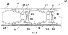
На фигуре 4 показан типичный поперечный разрез снарядов 35, загружаемых в ствол 39, который вложен в узел 30, изображенный на фигуре 2 или 3. Снаряды 35 данного варианта содержат порошковый антипирен в емкости 32, образованной в основной части снаряда, и метательный заряд в камере высокого давления 36 в хвостовой части снаряда. При воспламенении продукты сгорания метательного заряда проходят через отверстия 38 в камеру низкого давления 33, чтобы выбросить передний снаряд 35 из ствола 39.Figure 4 shows a typical cross-section of
Снаряды 35 входят в плотный контакт со стенками канала ствола 39 через коническую гильзу 31, которая крепится на снаряде с помощью фланца 37 гильзы.
Гильза 31 проходит назад от головки снаряда, составляя сборку прокладок для определения камеры низкого давления 33 и примыкая к смежному расположенному сзади снаряду. Гильза 31 включает заклинивающую поверхность 34, которая входит в контакт с дополнительной поверхностью на головке снаряда, так что когда сжимающие нагрузки прилагаются к колонке снарядов, загруженных в ствол 39, по меньшей мере, часть гильзы 31 может входит в плотный рабочий контакт с каналом ствола.The
На фигуре 5 представлена функциональная блок-схема системы управления 40 для использования в бортовом узле пожаротушения еще одного варианта настоящего изобретения. Система управления включает центральный процессор 41, который получает данные от различных датчиков, включая обычные датчики, устанавливаемые на самолете, несущем гондолу 54 с множеством снарядов, как описано выше. Например, радиолокационный высотомер 42 обеспечивает индикацию в реальном времени высоты самолета над уровнем земли, а приемник глобальной системы позиционирования (ГСП) 43 обеспечивает информацию о положении самолета. Цифровая база данных карты местности 44 может быть использована с учетом скорости самолета и информации о курсе 48, чтобы определить участок местности, который будет пересечен при полете, и воспроизведения карты местности 51 на дисплее 45 для использования этих данных оператором. Положение самолета в реальном времени может быть представлено на дисплее соответствующим изображением 50, сформированным на основе данных, полученных от приемника ГСП 43.The figure 5 presents a functional block diagram of a control system 40 for use in the airborne fire extinguishing unit of another embodiment of the present invention. The control system includes a
Система управления 40 также включает входы для подсистемы наведения, которая в данном варианте содержит систему инфракрасных датчиков (ИФ) 46. Инфракрасный датчик 46, как правило, "просматривает" пространство впереди самолета, чтобы создать карту пожара 52, изображающую различные уровни интенсивности пламени, которая нагадывается на карту местности, отображаемую на дисплее 45. Оператор может просматривать всю местность и карту района пожара на дисплее 45 и определять участки пламени 47, на которые нужно направить самолет, например, с помощью указателя 53, соединенного с дисплеем 45. Обозначенный целевой район пламени 47 может использоваться в программе центрального процессора вместе с определенной высотой и положением самолета для вычисления ожидаемого времени полета снарядов и для наведения снарядов и формирования сигналов выпуска снарядов из гондолы 54 и, если требуется, сигналов задержки взрыва для отдельных снарядов. Плотность снарядов может быть соответственно определена автоматически на основе интенсивности пламени, показанной инфракрасными датчиками 46, и задержки взрыва относительно обозначенной высоты для рассеивания антипирена из снарядов.The control system 40 also includes inputs for the guidance subsystem, which in this embodiment includes a system of infrared sensors (IF) 46. The
В альтернативном устройстве наведение и выстрел снарядов гондолы и программирование задержки взрыва может осуществляется в зависимости от интенсивности пламени. Это устройство может использоваться для наведения снарядов на горячие точки по большому фронту пламени.In an alternative device, guidance and firing of nacelle shells and programming of the delay of the explosion may be carried out depending on the intensity of the flame. This device can be used to aim shells at hot spots along a large flame front.
Способ и его устройство, настоящему изобретению обеспечивают точное наведение на горячие точки в пламени, таким образом, предотвращая или, по меньшей мере, сдерживая распространение огня.The method and its device, the present invention provide accurate guidance on hot spots in the flame, thus preventing or at least containing the spread of fire.
Кроме того, там, где возникает угроза для строений и/или для жизни людей, опасный фронт пламени может быть обработан антипиреном с большей точностью.In addition, where there is a threat to buildings and / or human life, a dangerous flame front can be flame retardant with greater accuracy.
Приведенное выше описание дано только в качестве иллюстрации, и любые модификации изобретения могут быть сделаны специалистами в данной области, не выходя из объема изобретения. Полный объем изобретения охвачен приведенной ниже формулой изобретения.The above description is given by way of illustration only, and any modifications to the invention may be made by those skilled in the art without departing from the scope of the invention. The full scope of the invention is covered by the following claims.
Claims (25)
Applications Claiming Priority (2)
| Application Number | Priority Date | Filing Date | Title |
|---|---|---|---|
| AUPR6197A AUPR619701A0 (en) | 2001-07-06 | 2001-07-06 | Fire fighting |
| AUPR6197.01 | 2001-07-06 |
Publications (2)
| Publication Number | Publication Date |
|---|---|
| RU2004101228A RU2004101228A (en) | 2004-12-27 |
| RU2288761C2 true RU2288761C2 (en) | 2006-12-10 |
Family
ID=3830161
Family Applications (1)
| Application Number | Title | Priority Date | Filing Date |
|---|---|---|---|
| RU2004101228/12A RU2288761C2 (en) | 2001-07-06 | 2002-07-03 | Method of the fire-fighting (versions) and the device for its realization |
Country Status (14)
| Country | Link |
|---|---|
| US (1) | US20040238186A1 (en) |
| EP (1) | EP1404415A4 (en) |
| JP (1) | JP2004532716A (en) |
| KR (1) | KR20040015333A (en) |
| CN (1) | CN1525873A (en) |
| AU (1) | AUPR619701A0 (en) |
| BR (1) | BR0211236A (en) |
| CA (1) | CA2452161A1 (en) |
| IL (1) | IL159733A0 (en) |
| MX (1) | MXPA04000165A (en) |
| RU (1) | RU2288761C2 (en) |
| TW (1) | TW200410743A (en) |
| WO (1) | WO2003004102A1 (en) |
| ZA (1) | ZA200400032B (en) |
Cited By (5)
| Publication number | Priority date | Publication date | Assignee | Title |
|---|---|---|---|---|
| CN105749458A (en) * | 2014-12-18 | 2016-07-13 | 常熟市福安消防设备有限公司 | Throwing-type fire-fighting fire-extinguishing bomb |
| RU2591616C1 (en) * | 2015-07-13 | 2016-07-20 | Владимир Александрович Парамошко | Method for rapid explosive fire extinguishing of range fire |
| RU2593132C1 (en) * | 2015-07-13 | 2016-07-27 | Владимир Александрович Парамошко | Method for rapid explosive fire extinguishing of crown forest fire |
| RU2594146C1 (en) * | 2015-07-13 | 2016-08-10 | Владимир Александрович Парамошко | Method for prompt explosive fire extinguishing of a fire in hazardous facilities, zones and units of industrial, transport and agriculture |
| RU2780170C2 (en) * | 2021-03-26 | 2022-09-20 | Владимир Дмитриевич Захматов | Method for precise large-scale fire extinguishing by flocks of unmanned aerial vehicles creating multi-squalls, vortices, tornadoes |
Families Citing this family (24)
| Publication number | Priority date | Publication date | Assignee | Title |
|---|---|---|---|---|
| US7210537B1 (en) * | 2002-01-23 | 2007-05-01 | Mcneil Steven D | Method of controlling fires |
| EP1625341A4 (en) | 2003-05-02 | 2010-09-29 | Metal Storm Ltd | Combined electrical mechanical firing systems |
| DE10346163A1 (en) * | 2003-10-04 | 2005-05-04 | Diehl Bgt Defence Gmbh & Co Kg | Missile for fire fighting |
| AU2007231570B2 (en) * | 2006-03-22 | 2011-12-08 | Federal Express Corporation | Fire suppressant device and method, including expansion agent |
| US20080087444A1 (en) * | 2006-10-12 | 2008-04-17 | Held Jerry M | New technique for fire fighting-large scale open fires |
| FR2912922B1 (en) | 2007-02-22 | 2009-06-26 | Nexter Munitions Sa | FIRE EXTINGUISHING DEVICE |
| DE102007061108B4 (en) * | 2007-12-19 | 2012-11-22 | Herbert Steinleitner | Method and apparatus for firefighting |
| ES2345380B1 (en) * | 2009-03-20 | 2011-07-11 | Fermin Caraballo Sanchez | SET REMOTE FIRE EXTINGUISHING SYSTEM. |
| WO2013102213A1 (en) * | 2011-12-30 | 2013-07-04 | Chandler Partners International, Ltd. | Fire fighting systems and methods |
| EP3527493B1 (en) | 2012-01-27 | 2020-08-26 | Simplex Manufacturing Co. | Aerial fire suppression system |
| CN102847251B (en) * | 2012-09-19 | 2014-07-23 | 邓全龙 | Pneumatic window breaking fire extinguishing cannon |
| ES2394339B1 (en) * | 2012-10-01 | 2013-09-19 | Juan Pedro RIVAS LÓPEZ | Device for the prevention, containment and / or extinguishing of fires, and associated procedure |
| CN103656938B (en) * | 2013-12-30 | 2015-11-25 | 长春远洋特种工业材料有限公司 | Matrix form pulse multitube launches fire extinguishing equipment and fire fighting truck |
| US10406390B2 (en) | 2016-08-09 | 2019-09-10 | Simplex Manufacturing Co. | Aerial fire suppression system |
| US11224773B1 (en) * | 2017-03-30 | 2022-01-18 | Michael Shane Strickland | Fire suppression and safety system |
| US10388049B2 (en) * | 2017-04-06 | 2019-08-20 | Honeywell International Inc. | Avionic display systems and methods for generating avionic displays including aerial firefighting symbology |
| CN106823212A (en) * | 2017-04-21 | 2017-06-13 | 杨宏兵 | Ball of putting out the fire moves release platform and ball method for releasing of putting out the fire |
| CN107537120A (en) * | 2017-08-28 | 2018-01-05 | 王秋辉 | A kind of fire extinguishing bullet launching device, fire-fighting aircraft and extinguishing method |
| US11008100B1 (en) * | 2017-12-11 | 2021-05-18 | Andre S. Richardson | Helicopter-mounted fire suppression delivery system |
| DE102018000298A1 (en) | 2018-01-16 | 2019-07-18 | Shagin Chagaev | A fire extinguisher of a hanging type for extinguishing forest and steppe fires |
| CN110433416A (en) * | 2019-07-10 | 2019-11-12 | 湖南宏兵安防设备有限公司 | A kind of multi-level high-altitude full coverage type extinguishing method |
| RU2742430C1 (en) * | 2020-06-17 | 2021-02-05 | Олег Александрович Рыбин | Fire extinguishing method |
| CN113908480B (en) * | 2021-09-14 | 2023-05-12 | 淮海工业集团有限公司 | Fire extinguishing bomb initial velocity measurement system |
| WO2023200248A1 (en) * | 2022-04-12 | 2023-10-19 | 온누리컴퍼니 유한회사 | Fire extinguishing grenade, and launcher and launching method thereof |
Family Cites Families (17)
| Publication number | Priority date | Publication date | Assignee | Title |
|---|---|---|---|---|
| US2665768A (en) * | 1951-09-14 | 1954-01-12 | Lee I Talbot | Fire extinguishing bomb |
| US3065798A (en) * | 1960-07-01 | 1962-11-27 | John E Rall | Projectile fire extinguishing device |
| DE2518918A1 (en) * | 1975-04-29 | 1976-11-11 | Anthony Edmund Briddon | Large fires extinguished from safe distance by projectile - containing extinguishing agent spread by explosive or pressurised gas |
| AU568980B2 (en) * | 1985-06-04 | 1988-01-14 | Fujitsu Limited | Method and device for timing pull-in of receiving equipment |
| IL77783A (en) * | 1986-02-04 | 1991-04-15 | Stolov Michael | Arrangement and method for propelling liquids over long distances |
| US5038866A (en) * | 1986-11-21 | 1991-08-13 | Santa Barbara Research Center | Powder discharge apparatus |
| US4964469A (en) * | 1988-05-18 | 1990-10-23 | Smith Wayne D | Device for broadcasting dry material by explosive force |
| US5883329A (en) | 1993-03-12 | 1999-03-16 | O'dwyer; James Michael | Barrel assembly |
| AUPN426595A0 (en) | 1995-07-19 | 1995-10-05 | O'dwyer, James Michael | Firearms |
| AUPO315696A0 (en) | 1996-10-23 | 1996-11-14 | O'dwyer, James Michael | Projectile firing weapons |
| RU2121856C1 (en) * | 1997-04-21 | 1998-11-20 | Государственный научно-исследовательский институт машиностроения | Fire-extinguishing apparatus |
| AUPP961299A0 (en) | 1999-04-07 | 1999-05-06 | Metal Storm Limited | Projectile launching apparatus |
| AU765812B2 (en) * | 1999-04-07 | 2003-10-02 | Metal Storm Limited | Projectile launching apparatus and methods for fire fighting |
| AU748952C (en) * | 1999-04-07 | 2003-01-09 | Metal Storm Limited | Projectile launching apparatus and method for seismic exploration of a remote site |
| CZ20023815A3 (en) * | 2000-05-18 | 2003-04-16 | Paul Edwards | System for discharging burning inhibitor |
| US6470805B1 (en) * | 2001-04-30 | 2002-10-29 | The United States Of America As Represented By The Secretary Of The Navy | Fire retardant bio-friendly practice munition |
| US6832604B1 (en) * | 2002-01-22 | 2004-12-21 | Paul Thompson | Pneumatic delivery system for projectiles |
-
2001
- 2001-07-06 AU AUPR6197A patent/AUPR619701A0/en not_active Abandoned
-
2002
- 2002-07-03 WO PCT/AU2002/000854 patent/WO2003004102A1/en not_active Application Discontinuation
- 2002-07-03 ZA ZA200400032A patent/ZA200400032B/en unknown
- 2002-07-03 KR KR10-2004-7000154A patent/KR20040015333A/en not_active Application Discontinuation
- 2002-07-03 JP JP2003510111A patent/JP2004532716A/en active Pending
- 2002-07-03 CN CNA028136233A patent/CN1525873A/en active Pending
- 2002-07-03 US US10/482,664 patent/US20040238186A1/en not_active Abandoned
- 2002-07-03 EP EP02742508A patent/EP1404415A4/en not_active Withdrawn
- 2002-07-03 RU RU2004101228/12A patent/RU2288761C2/en not_active IP Right Cessation
- 2002-07-03 CA CA002452161A patent/CA2452161A1/en not_active Abandoned
- 2002-07-03 MX MXPA04000165A patent/MXPA04000165A/en unknown
- 2002-07-03 IL IL15973302A patent/IL159733A0/en unknown
- 2002-07-03 BR BR0211236-1A patent/BR0211236A/en not_active IP Right Cessation
- 2002-12-19 TW TW091136719A patent/TW200410743A/en unknown
Cited By (5)
| Publication number | Priority date | Publication date | Assignee | Title |
|---|---|---|---|---|
| CN105749458A (en) * | 2014-12-18 | 2016-07-13 | 常熟市福安消防设备有限公司 | Throwing-type fire-fighting fire-extinguishing bomb |
| RU2591616C1 (en) * | 2015-07-13 | 2016-07-20 | Владимир Александрович Парамошко | Method for rapid explosive fire extinguishing of range fire |
| RU2593132C1 (en) * | 2015-07-13 | 2016-07-27 | Владимир Александрович Парамошко | Method for rapid explosive fire extinguishing of crown forest fire |
| RU2594146C1 (en) * | 2015-07-13 | 2016-08-10 | Владимир Александрович Парамошко | Method for prompt explosive fire extinguishing of a fire in hazardous facilities, zones and units of industrial, transport and agriculture |
| RU2780170C2 (en) * | 2021-03-26 | 2022-09-20 | Владимир Дмитриевич Захматов | Method for precise large-scale fire extinguishing by flocks of unmanned aerial vehicles creating multi-squalls, vortices, tornadoes |
Also Published As
| Publication number | Publication date |
|---|---|
| EP1404415A1 (en) | 2004-04-07 |
| BR0211236A (en) | 2004-08-10 |
| MXPA04000165A (en) | 2004-05-21 |
| KR20040015333A (en) | 2004-02-18 |
| JP2004532716A (en) | 2004-10-28 |
| CN1525873A (en) | 2004-09-01 |
| WO2003004102A1 (en) | 2003-01-16 |
| TW200410743A (en) | 2004-07-01 |
| ZA200400032B (en) | 2007-12-27 |
| IL159733A0 (en) | 2004-06-20 |
| EP1404415A4 (en) | 2004-09-29 |
| US20040238186A1 (en) | 2004-12-02 |
| CA2452161A1 (en) | 2003-01-16 |
| AUPR619701A0 (en) | 2001-08-02 |
Similar Documents
| Publication | Publication Date | Title |
|---|---|---|
| RU2288761C2 (en) | Method of the fire-fighting (versions) and the device for its realization | |
| US6860187B2 (en) | Projectile launching apparatus and methods for fire fighting | |
| RU2293281C2 (en) | Missile for throwing charges and modes of its using | |
| US20160175626A1 (en) | Fire retardation missile system and method | |
| KR100863829B1 (en) | Projectile firing apparatus | |
| RU2247922C2 (en) | False target | |
| US20050139363A1 (en) | Fire suppression delivery system | |
| KR20020065588A (en) | Area denial | |
| KR20070104344A (en) | Device for smothering a fire in a building | |
| RU2193906C2 (en) | Fire-extinguishing method and rocket-type fire-extinguishers for effectuating method | |
| KR20230174833A (en) | Fire-extinguishing bomb for fire suppression | |
| AU765812B2 (en) | Projectile launching apparatus and methods for fire fighting | |
| US20180099168A1 (en) | Fire retardation missile system and method | |
| RU2324138C2 (en) | Armored vehicle protection method and arrangement | |
| AU2002344678A1 (en) | Fire fighting method and apparatus | |
| US20230073113A1 (en) | Interceptor | |
| KR101484690B1 (en) | Rapid Fire Extinguishing Device using Fuel-Air Explosive Technology | |
| RU2651319C1 (en) | Method for armored vehicles protection and device for its implementation | |
| KR20230146489A (en) | Extinguishing grenade for fire suppression and its launcher and firing method | |
| KR20230146419A (en) | Extinguishing grenade for fire suppression and its launcher and firing method | |
| KR20050016264A (en) | Projectile for radially deploying sub-projectiles | |
| KR200287145Y1 (en) | Fire suppression digestion coal structure that use propulsion coal | |
| KR20170110432A (en) | Methodfor extinguishing forest fire using grenade | |
| TW200412418A (en) | Projectile for radially deploying sub-projectiles | |
| AU2002325618A1 (en) | Projectile for radially deploying sub-projectiles |
Legal Events
| Date | Code | Title | Description |
|---|---|---|---|
| MM4A | The patent is invalid due to non-payment of fees |
Effective date: 20070704 |