RU2287863C2 - Representation of consecutive sections for information blocks - Google Patents
Representation of consecutive sections for information blocks Download PDFInfo
- Publication number
- RU2287863C2 RU2287863C2 RU2003133984/28A RU2003133984A RU2287863C2 RU 2287863 C2 RU2287863 C2 RU 2287863C2 RU 2003133984/28 A RU2003133984/28 A RU 2003133984/28A RU 2003133984 A RU2003133984 A RU 2003133984A RU 2287863 C2 RU2287863 C2 RU 2287863C2
- Authority
- RU
- Russia
- Prior art keywords
- information
- recording
- recorded
- section
- zone
- Prior art date
Links
Images


Classifications
-
- G—PHYSICS
- G11—INFORMATION STORAGE
- G11B—INFORMATION STORAGE BASED ON RELATIVE MOVEMENT BETWEEN RECORD CARRIER AND TRANSDUCER
- G11B20/00—Signal processing not specific to the method of recording or reproducing; Circuits therefor
- G11B20/10—Digital recording or reproducing
- G11B20/12—Formatting, e.g. arrangement of data block or words on the record carriers
-
- G—PHYSICS
- G11—INFORMATION STORAGE
- G11B—INFORMATION STORAGE BASED ON RELATIVE MOVEMENT BETWEEN RECORD CARRIER AND TRANSDUCER
- G11B27/00—Editing; Indexing; Addressing; Timing or synchronising; Monitoring; Measuring tape travel
- G11B27/10—Indexing; Addressing; Timing or synchronising; Measuring tape travel
- G11B27/19—Indexing; Addressing; Timing or synchronising; Measuring tape travel by using information detectable on the record carrier
- G11B27/28—Indexing; Addressing; Timing or synchronising; Measuring tape travel by using information detectable on the record carrier by using information signals recorded by the same method as the main recording
- G11B27/32—Indexing; Addressing; Timing or synchronising; Measuring tape travel by using information detectable on the record carrier by using information signals recorded by the same method as the main recording on separate auxiliary tracks of the same or an auxiliary record carrier
- G11B27/327—Table of contents
- G11B27/329—Table of contents on a disc [VTOC]
-
- G—PHYSICS
- G11—INFORMATION STORAGE
- G11B—INFORMATION STORAGE BASED ON RELATIVE MOVEMENT BETWEEN RECORD CARRIER AND TRANSDUCER
- G11B27/00—Editing; Indexing; Addressing; Timing or synchronising; Monitoring; Measuring tape travel
- G11B27/002—Programmed access in sequence to a plurality of record carriers or indexed parts, e.g. tracks, thereof, e.g. for editing
-
- G—PHYSICS
- G11—INFORMATION STORAGE
- G11B—INFORMATION STORAGE BASED ON RELATIVE MOVEMENT BETWEEN RECORD CARRIER AND TRANSDUCER
- G11B27/00—Editing; Indexing; Addressing; Timing or synchronising; Monitoring; Measuring tape travel
- G11B27/10—Indexing; Addressing; Timing or synchronising; Measuring tape travel
- G11B27/102—Programmed access in sequence to addressed parts of tracks of operating record carriers
- G11B27/105—Programmed access in sequence to addressed parts of tracks of operating record carriers of operating discs
-
- G—PHYSICS
- G11—INFORMATION STORAGE
- G11B—INFORMATION STORAGE BASED ON RELATIVE MOVEMENT BETWEEN RECORD CARRIER AND TRANSDUCER
- G11B27/00—Editing; Indexing; Addressing; Timing or synchronising; Monitoring; Measuring tape travel
- G11B27/10—Indexing; Addressing; Timing or synchronising; Measuring tape travel
- G11B27/19—Indexing; Addressing; Timing or synchronising; Measuring tape travel by using information detectable on the record carrier
- G11B27/24—Indexing; Addressing; Timing or synchronising; Measuring tape travel by using information detectable on the record carrier by sensing features on the record carrier other than the transducing track ; sensing signals or marks recorded by another method than the main recording
-
- G—PHYSICS
- G11—INFORMATION STORAGE
- G11B—INFORMATION STORAGE BASED ON RELATIVE MOVEMENT BETWEEN RECORD CARRIER AND TRANSDUCER
- G11B27/00—Editing; Indexing; Addressing; Timing or synchronising; Monitoring; Measuring tape travel
- G11B27/10—Indexing; Addressing; Timing or synchronising; Measuring tape travel
- G11B27/19—Indexing; Addressing; Timing or synchronising; Measuring tape travel by using information detectable on the record carrier
- G11B27/28—Indexing; Addressing; Timing or synchronising; Measuring tape travel by using information detectable on the record carrier by using information signals recorded by the same method as the main recording
- G11B27/30—Indexing; Addressing; Timing or synchronising; Measuring tape travel by using information detectable on the record carrier by using information signals recorded by the same method as the main recording on the same track as the main recording
- G11B27/3027—Indexing; Addressing; Timing or synchronising; Measuring tape travel by using information detectable on the record carrier by using information signals recorded by the same method as the main recording on the same track as the main recording used signal is digitally coded
-
- G—PHYSICS
- G11—INFORMATION STORAGE
- G11B—INFORMATION STORAGE BASED ON RELATIVE MOVEMENT BETWEEN RECORD CARRIER AND TRANSDUCER
- G11B2220/00—Record carriers by type
- G11B2220/20—Disc-shaped record carriers
- G11B2220/21—Disc-shaped record carriers characterised in that the disc is of read-only, rewritable, or recordable type
- G11B2220/215—Recordable discs
- G11B2220/216—Rewritable discs
-
- G—PHYSICS
- G11—INFORMATION STORAGE
- G11B—INFORMATION STORAGE BASED ON RELATIVE MOVEMENT BETWEEN RECORD CARRIER AND TRANSDUCER
- G11B2220/00—Record carriers by type
- G11B2220/20—Disc-shaped record carriers
- G11B2220/21—Disc-shaped record carriers characterised in that the disc is of read-only, rewritable, or recordable type
- G11B2220/215—Recordable discs
- G11B2220/218—Write-once discs
-
- G—PHYSICS
- G11—INFORMATION STORAGE
- G11B—INFORMATION STORAGE BASED ON RELATIVE MOVEMENT BETWEEN RECORD CARRIER AND TRANSDUCER
- G11B2220/00—Record carriers by type
- G11B2220/20—Disc-shaped record carriers
- G11B2220/25—Disc-shaped record carriers characterised in that the disc is based on a specific recording technology
- G11B2220/2537—Optical discs
- G11B2220/2545—CDs
-
- G—PHYSICS
- G11—INFORMATION STORAGE
- G11B—INFORMATION STORAGE BASED ON RELATIVE MOVEMENT BETWEEN RECORD CARRIER AND TRANSDUCER
- G11B2220/00—Record carriers by type
- G11B2220/20—Disc-shaped record carriers
- G11B2220/25—Disc-shaped record carriers characterised in that the disc is based on a specific recording technology
- G11B2220/2537—Optical discs
- G11B2220/2562—DVDs [digital versatile discs]; Digital video discs; MMCDs; HDCDs
Abstract
Description
Изобретение относится к устройству для записи по меньшей мере одного блока информации на дорожке в области записи на носителе информации, причем такой блок информации содержит слова данных и слова исправления ошибок для исправления ошибок в пределах блока информации, и такая дорожка имеет предварительно сформированную информацию о расположении, которая указывает позиции для записи блоков информации, такое устройство содержит средство записи для записи меток, представляющих блоки информации, и средство управления для записи и извлечения информации о расположении, которая указывает расположение записанных блоков информации.The invention relates to a device for recording at least one block of information on a track in a recording area on a storage medium, such a block of information comprising data words and error correction words for correcting errors within the information block, and such a track has preformed location information, which indicates positions for recording information blocks, such a device comprises recording means for recording marks representing information blocks, and control means for recording and retrieving information on the location of Oia, which indicates the position of the recorded information blocks.
Изобретение дополнительно относится к способу записи по меньшей мере одного блока информации на дорожке в области записи на носителе информации, причем такой блок информации содержит слова данных и слова исправления ошибок для исправления ошибок в пределах блока информации, и такая дорожка имеет предварительно сформированную информацию о расположении, которая указывает позиции для записи блоков информации, такой способ содержит запись меток, представляющих блоки информации, и запись и извлечение информации о расположении, которая указывает расположение записанных блоков информации.The invention further relates to a method for recording at least one block of information on a track in a recording area on a storage medium, such a block of information comprising data words and error correction words for error correction within the information block, and such a track has preformed location information, which indicates positions for recording information blocks, such a method comprises recording marks representing information blocks, and recording and retrieving location information that It binds the location of the recorded information blocks.
Изобретение дополнительно относится к носителю информации, содержащему дорожку в области записи для записи по меньшей мере одного блока информации, причем такой блок информации содержит слова данных и слова исправления ошибок для исправления ошибок в пределах блока информации, и такая дорожка имеет предварительно сформированную информацию о расположении, которая указывает позиции для записи блоков информации и имеет предварительно сформированную информацию управления для управления процессом записи.The invention further relates to a storage medium containing a track in the recording area for recording at least one block of information, wherein such a block of information contains data words and error correction words for error correction within the information block, and such a track has preformed location information, which indicates positions for recording blocks of information and has pre-formed control information for controlling the recording process.
Устройство и способ записи информационных сигналов на носителе информации известны из патента США 5124966 (PHN12887). Информация кодируется в блок информации, который содержит слова данных и слова исправления ошибок для исправления ошибок в пределах блока информации. Устройство содержит средство записи для записи меток, представляющих блоки информации. Информация по меньшей мере одного блока информации модулируется в модулированный сигнал и записывается на дорожке в предопределенных позициях, которые указаны с помощью информации о расположении на предварительно сформированной дорожке. Устройство имеет средство управления для записи и извлечения информации о расположении в специальной области на носителе информации, которая показывает расположение записанных блоков информации. Временное оглавление (TOC) записывается в специальной области и считывается во время записи последующих информационных сигналов. Временное оглавление (TOC) представляет информацию о расположении, которая показывает расположение записанных блоков информации. Каждый раз, когда записывается информационный сигнал, дополнительные данные должны быть записаны в специальной области. Для извлечения фактического состояния последней записанной информации специальная область должна полностью считываться. В однократно записываемом носителе информации, таком как записываемый компакт-диск (CD-R), данные о расположении не могут перезаписываться, и, следовательно, объем данных о расположении может быть большим.A device and method for recording information signals on a storage medium are known from US Pat. No. 5,214,966 (PHN12887). Information is encoded into an information block that contains data words and error correction words for error correction within the information block. The device comprises recording means for recording marks representing blocks of information. Information of at least one block of information is modulated into a modulated signal and recorded on a track at predetermined positions that are indicated using location information on a preformed track. The device has control means for recording and retrieving location information in a special area on the storage medium that shows the location of recorded information blocks. A temporary table of contents (TOC) is recorded in a special area and is read during the recording of subsequent information signals. A temporary table of contents (TOC) represents location information that shows the location of recorded blocks of information. Each time an information signal is recorded, additional data must be recorded in a special area. To extract the actual state of the last recorded information, a special area must be fully read. In a write-once storage medium, such as a recordable compact disc (CD-R), the location data cannot be overwritten, and therefore, the volume of the location data may be large.
Задачей изобретения является обеспечение более гибкой и надежной системы для записи данных о расположении.The objective of the invention is to provide a more flexible and reliable system for recording location data.
Для этой цели устройство, которое описано в начальном абзаце, отличается тем, что средство управления содержит средство отображения для определения, в какой секции записан блок информации, причем секция является одной из множества последовательных секций, составляющих область записи, и для записи случайного элемента сигнала в ячейку в области отображения носителя информации, причем ячейка в области отображения служит индикатором указанной секции, и длина случайного элемента сигнала существенно меньше, чем длина указанного блока информации, и средство обнаружения для извлечения из указанной области отображения информации о том, содержит ли секция по меньшей мере один блок информации, с помощью обнаружения присутствия записанных случайных элементов сигнала. Способ, описанный в начальном абзаце, отличается тем, что данный способ содержит этап определения того, в какой секции записан блок информации, причем секция является одной из множества последовательных секций, составляющих область записи, и этап записи случайного элемента сигнала в ячейке в области отображения носителя информации, причем данная ячейка в области отображения служит индикатором для указанной секции, и длина случайного элемента сигнала существенно меньше, чем длина указанного блока информации, и этап извлечения из указанной области отображения информации о том, содержит ли секция по меньшей мере один блок информации, с помощью обнаружения присутствия записанных случайных элементов сигнала. Случайный элемент сигнала означает сегмент сигнала, представляющий данные, которые могут иметь любое значение, которое включает в себя известную и/или фиксированную комбинацию. Преимуществом является то, что для определения объема данных, записанных в области записи, объем информации о расположении, подлежащей извлечению, самое большее, имеет размер области отображения. Следовательно, время реакции устройства на запрос на запись будет коротким.For this purpose, the device described in the initial paragraph is characterized in that the control means comprises a display means for determining in which section the information block is recorded, the section being one of a plurality of consecutive sections constituting the recording area and for recording a random signal element in a cell in the display area of the information medium, and the cell in the display area serves as an indicator of the indicated section, and the length of the random signal element is significantly less than the length of the specified information block ation, and detecting means for retrieving from said mapping area information on whether the section is at least one information block by detecting the presence of the recorded random signal elements. The method described in the initial paragraph is characterized in that the method comprises the step of determining in which section the information block is recorded, the section being one of a plurality of consecutive sections constituting the recording area, and the step of recording a random signal element in a cell in the medium display area information, and this cell in the display area serves as an indicator for the indicated section, and the length of the random signal element is significantly less than the length of the specified block of information, and the step of extracting from the specified of the information display area of whether the section contains at least one block of information by detecting the presence of recorded random signal elements. A random signal element means a signal segment representing data that can have any value that includes a known and / or fixed combination. An advantage is that to determine the amount of data recorded in the recording area, the amount of location information to be extracted is at most the size of the display area. Therefore, the response time of the device to the write request will be short.
Изобретение основано на следующем понимании. Во-первых, изобретатели увидели, что время реакции устройства записи на запрос на запись существенно зависит от объема информации о расположении, которая должна считываться. Во-вторых, изобретатели увидели, что объем информации о расположении может быть уменьшен посредством записи в область отображения, используя короткие случайные элементы сигнала. Длина элемента меньше, чем длина блока информации, и поэтому информация не может быть извлечена из записанных случайных элементов сигнала, но тот факт, была или нет записана ячейка, обеспечивает информацию о состоянии соответствующей секции в области записи диска.The invention is based on the following understanding. First, the inventors saw that the response time of a recorder to a write request substantially depends on the amount of location information to be read. Secondly, the inventors saw that the amount of location information can be reduced by writing to the display area using short random signal elements. The length of the element is less than the length of the information block, and therefore the information cannot be extracted from the recorded random signal elements, but the fact, whether or not the cell was recorded, provides information about the status of the corresponding section in the recording area of the disc.
Согласно второму аспекту изобретения носитель информации, который описан в начальном абзаце, отличается тем, что информация управления содержит информацию управления областью записи, которая указывает параметры, подлежащие записи для управления областью отображения, которая указывает, в каких секциях записаны блоки информации, причем секция является одной из множества последовательных секций, составляющих область записи, область отображения имеет ячейки для записи случайных элементов сигнала, ячейка в области отображения служит индикатором указанной секции, и длина случайного элемента сигнала существенно меньше, чем длина указанного блока информации. В варианте осуществления устройства средство управления сконфигурировано для извлечения информации управления с носителя информации, причем информация управления содержит информацию управления областью записи, которая указывает параметры, подлежащие записи для управления областью отображения. Преимуществом является то, что записывающее устройство может извлекать данные о расположении из области отображения в зависимости от типа носителя информации. Следовательно, различные типы носителей информации и различные конфигурации области отображения могут использоваться в одном записывающем устройстве.According to a second aspect of the invention, the storage medium described in the initial paragraph is characterized in that the control information comprises recording area management information that indicates parameters to be recorded for controlling a display area that indicates in which sections information blocks are recorded, wherein the section is one of the plurality of consecutive sections making up the recording area, the display area has cells for recording random signal elements, the cell in the display area serves as an ikator of the indicated section, and the length of the random signal element is significantly less than the length of the specified information block. In an embodiment of the device, the control means is configured to retrieve control information from the storage medium, the control information comprising recording area management information that indicates parameters to be recorded for controlling the display area. An advantage is that the recording device can retrieve location data from the display area depending on the type of storage medium. Therefore, various types of storage media and various display area configurations can be used in a single recording device.
В варианте осуществления устройства, в котором предварительно сформированная информация о расположении кодируется в кадрах адреса, имеющих длину кадра, длина элемента по существу равна длине кадра. Преимуществом является то, что расположение элемента соответствует кадрам адреса, и поэтому может легко определяться и считываться, используя схемы, уже существующие в устройстве для считывания блоков информации.In an embodiment of a device in which preformed location information is encoded in address frames having a frame length, the length of the element is substantially equal to the length of the frame. The advantage is that the location of the element corresponds to address frames, and therefore can be easily determined and read using circuits already existing in the device for reading blocks of information.
Следует отметить, что патент США №5293566 описывает записывающее устройство для записи носителя информации перезаписываемого типа. В секции управления диском записывается адрес последнего записанного сектора. Эта секция перезаписывается каждый раз, когда записывается новый информационный сигнал. Следовательно, считывание информации из секции управления диском, которая часто перезаписывается, может стать ненадежным из-за износа этой части носителя информации; и такой способ не подходит для носителей информации, которые записываются однократно.It should be noted that US patent No. 5293566 describes a recording device for recording a rewritable type of information medium. In the disk management section, the address of the last recorded sector is recorded. This section is overwritten every time a new information signal is recorded. Therefore, reading information from the disc management section, which is often overwritten, may become unreliable due to wear of this part of the storage medium; and this method is not suitable for storage media that are recorded once.
Эти и другие аспекты изобретения будут очевидны и объяснены дополнительно со ссылкой на варианты осуществления, описанные для примера в последующем описании и со ссылкой на сопроводительные чертежи, на которых:These and other aspects of the invention will be apparent and explained further with reference to embodiments described for example in the following description and with reference to the accompanying drawings, in which:
фиг.1а показывает носитель информации (вид сверху),figa shows a storage medium (top view),
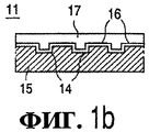
фиг.1б показывает носитель информации (сечение),figb shows a storage medium (section),
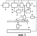
фиг.2 показывает записывающее устройство,figure 2 shows a recording device,
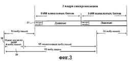
фиг.3 показывает соответствие ADIP и блоков информации,figure 3 shows the correspondence of ADIP and blocks of information,
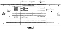
фиг.4 показывает структуру слова ADIP,4 shows the structure of the word ADIP,
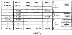
фиг.5 показывает структуру исправления ошибок ADIP,5 shows an ADIP error correction structure,
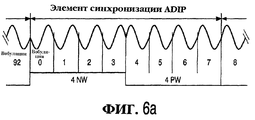
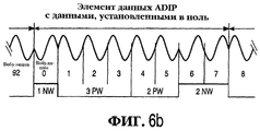
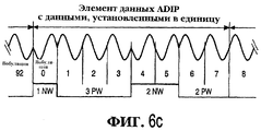
фиг.6а-6с показывает правила модуляции ADIP,6a-6c show ADIP modulation rules,
фиг.7 показывает таблицу физической информации диска,7 shows a table of physical information of a disk,
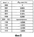
фиг.8 показывает времена коррекции переднего фронта,8 shows leading edge correction times,
фиг.9 показывает нумерацию секторов носителя информации,Fig.9 shows the numbering of sectors of the information carrier,
фиг.10 показывает структуру записанного односессионного диска,10 shows a structure of a recorded single-session disc,
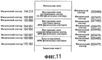
фиг.11 показывает внутреннюю область диска,11 shows the inner region of the disk,
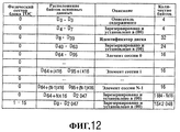
фиг.12 показывает формат блока ТОС,12 shows a format of a TOC block,
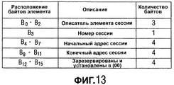
фиг.13 показывает элемент сессии,13 shows a session item,
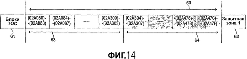
фиг.14 показывает индикаторы области записи,14 shows indicators of a recording area,
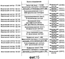
фиг.15 показывает вводную зону,Fig shows the introductory area,
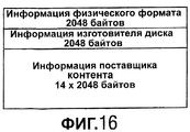
фиг.16 показывает структуру блока управляющих данных,Fig.16 shows the structure of the control data block,
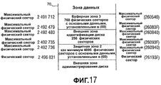
фиг.17 показывает выводную зону, и17 shows an exit zone, and
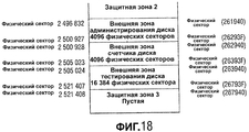
фиг.18 показывает внешнюю область диска.Fig. 18 shows an outer region of a disk.
Соответствующие элементы на различных фигурах имеют одинаковые ссылочные номера позиций.The corresponding elements in the various figures have the same reference numerals.
Фиг.1а показывает имеющий форму диска носитель 11 записи, имеющий дорожку 9 и центральное отверстие 10. Дорожка 9, которая является расположением последовательности записанных (или которые должны быть записаны) меток, которые представляют информацию, организована в соответствии со спиральным узором витков, составляющих по существу параллельные дорожки на информационном слое. Носитель информации, который может считываться оптическим образом, называется оптическим диском и имеет информационный слой с возможностью записи. Примерами записываемого диска являются CD-R и перезаписываемый компакт-диск (CD-RW) и записываемые версии цифровых универсальных дисков (DVD), например, формата DVD+RW. Дополнительные подробности о диске DVD могут быть найдены в документе: ECMA-267:120 mm DVD-Read-Only Disc - (1997). Информация представлена на информационном слое с помощью записи оптически обнаруживаемых меток вдоль дорожки, например кристаллические или аморфные метки в материале с фазовым переходом. Дорожка 9 на записываемом носителе информации обозначена предварительно вытисненной структурой дорожки, которая обеспечивается во время изготовления пустого носителя информации. Структура дорожки составлена, например, с помощью сплошной спиральной канавки 14, которая дает возможность головке записи-считывания следовать за дорожкой во время считывания. Структура дорожки содержит информацию о расположении, например адрес, для указания расположения единиц информации, обычно называемых блоками информации. Информация о расположении включает в себя определенные метки синхронизации для определения местонахождения начала таких блоков информации. Информация о расположении кодируется в кадрах модулированных вобуляций, как описано ниже.Fig. 1a shows a disc-
Фиг.1b - поперечное сечение по линии b-b носителя 11 информации записываемого типа, в котором прозрачная подложка 15 обеспечивается слоем 16 записи и защитным слоем 17. Защитный слой 17 может содержать дополнительный слой подложки, например как в DVD, где слой записи находится на подложке толщиной 0,6 мм, а дополнительная подложка толщиной 0,6 мм присоединена к его оборотной стороне. Предварительно сформированная сплошная спиральная канавка 14 может быть реализована как углубление или подъем материала подложки 15, или как изменение свойства материала по сравнению с его окружением.Fig. 1b is a cross-sectional view along the bb line of a recordable information medium 11 in which a
Носитель 11 информации предназначен для хранения информации, представленной кадрами, содержащими модулированные сигналы. Кадр - предопределенный объем данных, которым предшествует сигнал синхронизации. Обычно такие кадры также содержат коды исправления ошибок, например слова четности. Некоторое количество таких кадров составляет блок информации, причем блок информации содержит дополнительные слова исправления ошибок. Блок информации - наименьший элемент записи информации, из которого информация может быть надежно извлечена. Пример такой системы записи известен из системы DVD, в которой кадры содержат 172 слова данных и 10 слов четности, и 208 кадров составляют блок кода исправления ошибок (ECC).The
В варианте осуществления носителя информации дорожка 9 имеет предварительно сформированную информацию о расположении, которая показывает расположение записываемых блоков информации, и предварительно сформированную информацию управления для управления процессом записи. Информация управления содержит информацию управления областью записи, которая указывает параметры, подлежащие записи для управления областью отображения, которая показывает, в каких секциях записаны блоки информации. Система управления областью отображения описана ниже с устройством. Информация управления областью записи определяет конкретные параметры системы, подлежащие использованию для определенного носителя информации, например размер области отображения или размер секций.In an embodiment of the storage medium, track 9 has preformed location information that shows the location of the recorded information blocks, and preformed control information for controlling the recording process. The management information comprises recording area management information that indicates parameters to be recorded for controlling a display area that shows in which sections information blocks are recorded. The display area management system is described below with the device. Recording area management information determines specific system parameters to be used for a particular storage medium, for example, the size of a display area or the size of sections.
Фиг.2 показывает записывающее устройство для записи информации на носителе 11 информации записываемого или перезаписываемого типа, например CD-R или CD-RW. Устройство обеспечено средством записи для сканирования дорожки на носителе информации, причем данное средство включает в себя блок 21 привода для вращения носителя 11 информации, головку 22, блок 25 позиционирования для грубой установки головки 22 в радиальном направлении на дорожке и блок 20 управления. Головка 22 содержит оптическую систему известного типа для генерации лазерного луча 24, проходящего через оптические элементы и сфокусированного на пятне 23 лазерного луча на дорожке информационного слоя носителя информации. Лазерный луч 24 генерируется источником лазерного луча, например лазерным диодом. Головка дополнительно содержит (не показан) фокусирующий привод для перемещения фокуса лазерного луча 24 вдоль оптической оси указанного луча и привод слежения для точного позиционирования пятна 23 в радиальном направлении на центре дорожки. Привод слежения может содержать катушки индуктивности для радиального перемещения оптического элемента или, альтернативно, может настраиваться для изменения угла отражающего элемента. Для записи информации лучом управляют, чтобы с его помощью создать оптически обнаруживаемые метки на слое записи. Для считывания лазерный луч, отраженный от информационного слоя, обнаруживается датчиком обычного типа, например четырехэлементным диодом, расположенным в головке 22 для генерации сигнала считывания и сигналов других датчиков, которые включают в себя сигнал ошибки слежения и ошибки фокусирования для управления указанными приводами слежения и фокусирования. Сигнал считывания обрабатывается блоком 30 обработки считывания обычного типа, который включает в себя демодулятор, блок обратного форматирования и блок вывода для извлечения информации. Соответственно, средство извлечения для считывания информации включает в себя блок привода 21, головку 22, блок 25 позиционирования и блок 30 обработки считывания. Устройство содержит средство обработки записи для обработки входной информации с целью генерации сигнала записи для активации головки 22, причем данное средство содержит входной блок 27, и средство модулятора, содержащее блок 28 форматирования и модулятор 29. Блок 20 управления управляет записью и извлечением информации и может быть сконфигурирован для приема команд от пользователя или от главного компьютера. Блок 20 управления связан через линии 26 управления, например через системную шину, с указанным входным блоком 27, блоком 28 форматирования и модулятором 29, с блоком 30 обработки считывания, с приводом 21 диска и с блоком 25 позиционирования. Блок 20 управления содержит схему управления, например микропроцессор, память программ и управляющие логические элементы для выполнения процедур и функций согласно изобретению, как описано ниже со ссылкой на фиг.3-7. Блок 20 управления может также быть реализован как конечный автомат в логических схемах. Во время операции записи метки, представляющие информацию, формируются на носителе информации. Метки могут иметь любую оптически считываемую форму, например, быть в форме областей с коэффициентом отражения, отличным от их окружения, полученных при записи в таких материалах, как материалы, которые меняют цвет, химический состав или фазу, или в форме областей с направлением намагничивания, отличным от их окружения, полученных при записи в магнитооптическом материале. Запись и считывание информации для записи на оптических дисках и используемые правила форматирования, исправления ошибок и канального кодирования широко известны из предшествующего уровня техники, например из системы компакт-диска. Метки могут быть сформированы посредством пятна 23, сгенерированного на слое записи с помощью луча 24 электромагнитного излучения, обычно испускаемого лазерным диодом. Пользовательская информация представлена на входном блоке 27, который может содержать средство сжатия входных сигналов, таких как аналоговый аудио и/или видео сигнал, или цифровой несжатый аудио-/видеосигнал. Подходящее средство сжатия описано для аудиосигнала в документе WO 98/16014-A1 (PHN 16452), а для видеосигнала - в стандарте MPEG2, разработанном Экспертной группой по вопросам движущихся изображений. Входной блок 27 обрабатывает аудио- и/или видеосигналы в элементы информации, которые передают к блоку 28 форматирования для добавления управляющих данных и для форматирования данных согласно формату записи (как описано ниже), например, добавляя коды исправления ошибок (ECC) и/или используя перемежение. Для компьютерных приложений элементы информации могут передаваться к блоку 28 форматирования непосредственно. Отформатированные данные с выхода блока 28 форматирования передают к блоку 29 модуляции, который содержит, например, канальный кодер, для генерации модулированного сигнала, который активирует головку 22. Дополнительно блок 29 модуляции содержит средство синхронизации, предназначенное для включения последовательности синхронизирующих импульсов в модулированный сигнал. Отформатированные элементы, подаваемые на вход блока 29 модуляции, содержат информацию адреса и записываются в соответствующих адресуемых местах на носителе информации под управлением блока 20 управления. Устройство имеет средство отображения, содержащее блок 31 отображения, присоединенный к блоку 20 управления, и средство обнаружения, содержащее блок 32 обнаружения, присоединенный к блоку 20 управления и блоку 31 отображения. Блок 31 отображения имеет вывод 33, присоединенный к блоку 29 модуляции для записи информационных меток, в частности, случайного элемента сигнала, т.е. для записи сигнала случайных данных, имеющих длину кадра адреса, как описано ниже. Блок обнаружения имеет ввод 34 для обнаружения записанных меток, в частности для обнаружения высокочастотного сигнала, сгенерированного, когда записанная часть дорожки сканируется головкой 22. Блок 20 управления сконфигурирован для записи и извлечения данных о расположении, которые указывают расположение записанных блоков информации. Блок 31 отображения сконфигурирован для определения, в какой секции записан блок информации. Для этой цели носитель информации подразделяют на секции, причем каждая секция является одной из множества последовательных секций, составляющих область записи. После определения того, что в определенной секции был записан по меньшей мере один блок информации, блок отображения записывает случайный элемент сигнала в ячейку в области отображения носителя информации. Область отображения является областью носителя информации для управляющей информации о состоянии области записи, например о том, записаны ли некоторые части области записи или нет. Указанная ячейка в области отображения служит индикатором указанной определенной секции, и, следовательно, если ячейка была записана, то это указывает на то, что соответствующая секция содержит по меньшей мере один блок информации. Длина случайного элемента сигнала существенно меньше, чем длина указанного блока информации, и поэтому пространство, требуемое для области отображения, ограничено. Блок 32 обнаружения извлекает из указанной области отображения информацию о том, содержит ли секция по меньшей мере один блок информации, с помощью обнаружения присутствия записанных случайных элементов сигнала в определенных ячейках. Например, записанные блоки информации имеют последовательные адреса, и записанная ячейка с самым старшим адресом указывает на записанную секцию с самым старшим адресом в области записи. Средство обнаружения затем обнаруживает самый старший записанный адрес с помощью обнаружения записанной секции с самым старшим адресом с помощью информации из области отображения и затем последовательно обнаруживает самый старший записанный адрес с помощью обнаружения присутствия меток в нескольких местах в пределах записанной секции с самым старшим адресом в соответствии с систематическим поиском. Такой поиск может быть логарифмическим поиском, при котором адрес интерационно выбирается по существу в 50% от оставшейся неизвестной части секции для проверки того, присутствуют ли метки.Figure 2 shows a recording device for recording information on a
В варианте осуществления устройства область отображения имеет последовательный диапазон ячеек, соответствующих количеству секций, и средство отображения сконфигурировано для записи случайного элемента сигнала в ячейку в пределах диапазона ячеек, соответствующих расположению секций в пределах области записи. При практическом использовании размеры всех секций равны между собой, например размер каждой секции равен 640 блоков информации. Используя соответствующее количество секций, равное 256, вся область записи носителя информации оказывается охваченной. В варианте осуществления устройства средство 20 управления сконфигурировано для считывания информации управления с носителя информации. Информация управления является предварительно сформированной информацией, например, закодированной в вобуляции предварительно сформированной сплошной спиральной канавки, и она включает в себя параметры для управления процессом записи. Информация управления содержит информацию управления областью записи, которая указывает параметры, подлежащие записи для управления областью отображения. Блок 31 отображения и блок 32 обнаружения устанавливают в определенные значения с помощью параметров, которые указаны в информации управления областью записи, например размера области отображения. Информация управления областью записи может, например, содержать индикатор типа диска, указывающий определенный тип диска, который имеет предопределенный размер области отображения.In an embodiment of the device, the display area has a consecutive range of cells corresponding to the number of sections, and the display means is configured to record a random signal element into the cell within the range of cells corresponding to the location of the sections within the recording area. In practical use, the sizes of all sections are equal to each other, for example, the size of each section is 640 blocks of information. Using the corresponding number of sections equal to 256, the entire recording area of the information carrier is covered. In an embodiment of the device, control means 20 is configured to read control information from the storage medium. The control information is pre-formed information, for example, encoded in a wobble, a pre-formed solid spiral groove, and it includes parameters for controlling the recording process. The management information comprises recording area management information that indicates parameters to be recorded for managing the display area. The
В варианте осуществления носителя информации предварительно сформированная информация о расположении закодирована в кадрах адреса, имеющих длину кадра, например, как описано ниже для кадра ADIP. В варианте осуществления устройства блок отображения записывает случайные элементы сигнала, длина которых по существу равна длине кадра.In an embodiment of the storage medium, preformed location information is encoded in address frames having a frame length, for example, as described below for an ADIP frame. In an embodiment of the device, the display unit records random signal elements whose length is substantially equal to the length of the frame.
В варианте осуществления устройства средство управления сконфигурировано для инкрементной записи информации оглавления в зоне TOC на носителе информации, причем данная инкрементная запись начинается с начального адреса TOC зоны. Формат оглавления описан ниже. Средство 31 отображения сконфигурировано для записи области отображения в пределах зоны TOC от конечного адреса зоны TOC. Ячейки используются, начиная с самого старшего адреса в зоне TOC, и каждая последующая используемая секция обозначается с помощью записи ячейки, имеющей последующий меньший адрес. Подробное описание формата дается ниже, где ячейки называют индикаторами области записи. В варианте осуществления устройства средство 32 обнаружения содержит средство вычисления для вычисления адреса начала секции, содержащей самый старший записанный адрес номера физического сектора (PSN) с помощьюIn an embodiment of the device, the control means is configured to incrementally record the table of contents information in the TOC zone on the storage medium, and this incremental record starts from the starting address of the TOC zone. The format of the table of contents is described below. The display means 31 is configured to record the display area within the TOC zone from the end address of the TOC zone. Cells are used starting from the highest address in the TOC zone, and each subsequent section used is indicated by a cell record with the next lower address. A detailed description of the format is given below, where the cells are called indicators of the recording area. In an embodiment of the device, the detection means 32 comprises calculation means for calculating a start address of a section containing the oldest recorded physical sector number (PSN) address using
PSN=(E_TOC-L_MAP)*(R_SIZE/U_LEN)+S_RECA.PSN = (E_TOC-L_MAP) * (R_SIZE / U_LEN) + S_RECA.
В этой формуле E_TOC является конечным адресом зоны TOC, L_MAP - самый младший адрес записанной ячейки в области отображения, R_SIZE - размер каждой секции, U_LEN - длина случайного элемента сигнала и S_RECA - адрес начала первой секции в области записи. Практические значения даны ниже.In this formula, E_TOC is the end address of the TOC zone, L_MAP is the lowest address of the recorded cell in the display area, R_SIZE is the size of each section, U_LEN is the length of the random signal element, and S_RECA is the start address of the first section in the recording area. Practical values are given below.
Практический вариант осуществления системы для записи информации согласно изобретению является следующим. Система определяет механические, физические и оптические характеристики записываемых оптических дисков диаметром 120 мм с емкостью 4,7 Гбайт и 9,4 Гбайт. Она определяет качество записанных и незаписанных сигналов, формат данных и способ записи, таким образом учитывая обмен информацией с помощью таких дисков. Данные могут записываться однократно и считываться многократно, используя необратимый способ. Эти диски идентифицируются как DVD+R. Форма дорожки является следующей. Область записи, называемая "информационной зоной", должна содержать дорожки, сформированные одной спиральной канавкой. Каждая дорожка должна формироваться оборотом на 360° непрерывной спирали. Записи должны быть сделаны в данной канавке. Дорожки в информационной зоне содержат модулированное по фазе синусоидальное отклонение от номинальной средней линии, называемое вобуляцией, которая содержит информацию адресации, которая называется "адрес на предварительно сформированной сплошной спиральной канавке" или ADIP. Дорожки должны быть непрерывными в информационной зоне. Дорожки должны начинаться с радиуса 22,0 мм как максимум и заканчиваться как минимум на радиусе 58,50 мм. Траектория дорожки должна быть непрерывной спиралью от внутренней части (начало "вводной зоны") к внешней части (конец "выводной зоны"), когда диск вращается против часовой стрелки, если смотреть со стороны оптической головки. Шаг дорожки - расстояние, измеренное между усредненными средними линиями смежных дорожек, измеренное в радиальном направлении. Шаг дорожки должен быть 0,74 мкм±0,03 мкм. Среднее значение шага дорожки по информационной зоне должно быть 0,74 мкм±0,01 мкм. Вобуляция дорожек - синусоидальное отклонение от номинальной средней линии, с длиной волны 4,2656 мкм±0,0450 мкм (эквивалентно 32 канальным битам). Суммарное значение коэффициента нелинейных искажений (THD) генератора для генерации синусоидальной вобуляции должно быть ≤ -40 децибелов. Данная вобуляция модулируется по фазе с помощью инвертирования циклов вобуляции. Информацию, которая содержится в модуляции вобуляции, называют "адрес на предварительно сформированной сплошной спиральной канавке" или ADIP.A practical embodiment of a system for recording information according to the invention is as follows. The system determines the mechanical, physical and optical characteristics of recordable optical discs with a diameter of 120 mm with a capacity of 4.7 GB and 9.4 GB. It determines the quality of recorded and unrecorded signals, data format and recording method, thus taking into account the exchange of information using such discs. Data can be written once and read multiple times using an irreversible method. These discs are identified as DVD + R. The shape of the track is as follows. The recording area, called the "information zone", must contain tracks formed by a single spiral groove. Each track should be formed by a 360 ° rotation of a continuous spiral. Entries must be made in this groove. The tracks in the information zone contain a phase-modulated sinusoidal deviation from the nominal midline, called wobble, which contains addressing information called “address on a preformed solid spiral groove” or ADIP. Tracks must be continuous in the information area. Tracks should start at a radius of 22.0 mm as a maximum and end at least at a radius of 58.50 mm. The path of the track should be a continuous spiral from the inside (the beginning of the "input zone") to the outside (end of the "lead-out zone") when the disc rotates counterclockwise when viewed from the side of the optical head. Track pitch is the distance measured between the average center lines of adjacent tracks, measured in the radial direction. Track pitch should be 0.74 μm ± 0.03 μm. The average value of the track pitch in the information zone should be 0.74 μm ± 0.01 μm. Track wobble is a sinusoidal deviation from the nominal midline, with a wavelength of 4.2656 μm ± 0.0450 μm (equivalent to 32 channel bits). The total value of the THD of the generator for generating sinusoidal wobble should be ≤ -40 decibels. This wobble is modulated in phase by inverting the wobble cycles. The information that is contained in the wobble modulation is called an “address on a preformed solid spiral groove” or ADIP.
Фиг.3 показывает соответствие ADIP и блоков информации. Блоки 37 информации, подлежащие записи на диск, должны быть выровнены с информацией 39 ADIP, модулированной в вобуляции 38. Показано, что 93 вобуляции соответствуют 2 кадрам синхронизации, которые являются началом блока информации. Из каждых 93 вобуляций, 8 вобуляций модулированы по фазе с помощью информации ADIP. Дополнительно, 1 вобуляция равняется 32 канальным битам (=32Т), и один элемент ADIP =8 модулированным вобуляциям на 2 кадра синхронизации.Figure 3 shows the correspondence of ADIP and information blocks. The information blocks 37 to be written to the disc must be aligned with the
Фиг.4 показывает структуру слова ADIP. 52 элемента ADIP сгруппированы в одно слово ADIP. Это означает, что одно слово ADIP передает 4×13×2 кадра синхронизации ≡4 физических сектора. Каждое слово ADIP состоит из: 1 элемент синхронизации ADIP +51 элемент данных ADIP. Элемент синхронизации ADIP=4 инвертированных вобуляции для слова синхронизации +4 монотонных вобуляции. Элемент данных ADIP=1 инвертированная вобуляция для бита синхронизации +3 монотонных вобуляции +4 вобуляции, представляющих один бит данных. (см. 0)Figure 4 shows the structure of the word ADIP. 52 ADIP elements are grouped into a single ADIP word. This means that one ADIP word transmits 4 × 13 × 2 synchronization frames ≡4 physical sectors. Each ADIP word consists of: 1 ADIP synchronization element +51 ADIP data element. Synchronization element ADIP = 4 inverted wobbles for a synchronization word +4 monotonic wobbles. Data item ADIP = 1 inverted wobble for synchronization bit +3 monotonic wobble + 4 wobble representing one data bit. (see 0)
Информация, содержащаяся в битах данных слова ADIP, является следующей:The information contained in the data bits of the word ADIP is as follows:
бит 1: этот бит зарезервирован и должен быть установлен в ноль.bit 1: this bit is reserved and should be set to zero.
биты 2-23: эти 22 бита содержат физический адрес. Бит 2 данных - старший значащий бит (MSB), а бит 23 данных - младший значащий бит (LSB). Адреса увеличиваются на единицу для каждого следующего слова ADIP. Первый адрес в информационной зоне должен быть таким, что физический адрес (00C000) расположен на радиусе ![]()
![]()
биты 24-31: эти 8 битов содержат вспомогательную информацию о диске, например записываемую управляющую информацию. В зоне данных и выводной зоне диска вспомогательные байты должны быть установлены в (00). Во вводной зоне диска вспомогательные байты должны использоваться следующим образом: биты 24-31 из 256 последовательных слов ADIP должны формировать один вспомогательный кадр ADIP с 256 байтами информации. Первый байт каждого вспомогательного кадра ADIP должен быть расположен в слове ADIP с физическим адресом, который кратен 256 (физический адрес=(xxxx00)). Содержимое этих 256 байтов определено на фиг.7.bits 24-31: these 8 bits contain auxiliary disk information, such as recorded control information. In the data zone and the output zone of the disk, auxiliary bytes must be set to (00). In the input zone of the disk, auxiliary bytes should be used as follows: bits 24-31 of 256 consecutive ADIP words should form one auxiliary ADIP frame with 256 bytes of information. The first byte of each auxiliary ADIP frame must be located in the ADIP word with a physical address that is a multiple of 256 (physical address = (xxxx00)). The contents of these 256 bytes are defined in FIG.
биты 32-51: эти 20 битов содержат биты четности для исправления ошибок для информации ADIP.bits 32-51: these 20 bits contain parity bits for error correction for ADIP information.
Фиг.5 показывает структуру исправления ошибок ADIP. Для исправления ошибок ADIP биты данных ADIP сгруппированы в 4-битовые слоги. Отображение битов данных в массив слогов описано на фиг.5. Бит 0 - фиктивный бит, который должен рассматриваться как установленный в ноль для блока коррекции ошибок.5 shows an ADIP error correction structure. To correct ADIP errors, ADIP data bits are grouped into 4-bit syllables. The mapping of data bits into an array of syllables is described in FIG. 5.
Создается основанный на слогах код Рида-Соломона (13, 8, 6), из которого 5 слогов четности с N8 по N12 определяются полиномиальным остатком R (x):A syllable-based Reed-Solomon code is created (13, 8, 6), from which 5 parity syllables N8 through N12 are determined by the polynomial remainder R (x):
![]()
![]()
гдеWhere
![]()
![]()
![]()
![]()
α - первообразный корень 0010 из примитивного многочлена P(x)=x4+x+1.α is the
Все биты 5 слогов четности с N8 по N12 должны быть инвертированы перед записью.All
Фиг.6 показывает правила модуляции ADIP. Элементы ADIP модулируются с помощью инвертирования некоторых из 8 циклов вобуляции. Фиг.6a показывает модуляцию слова синхронизации ADIP, фиг.6b показывает модуляцию нулевого бита ADIP, и фиг.6c показывает модуляцию единичного бита ADIP, на которых6 shows ADIP modulation rules. ADIP elements are modulated by inverting some of the 8 wobble cycles. Fig.6a shows the modulation of the ADIP synchronization word, Fig.6b shows the modulation of the zero bit ADIP, and Fig.6c shows the modulation of a single ADIP bit, on which
- PW - положительная вобуляция, начало движения по которой направлено к внутренней части диска;- PW - positive wobble, the beginning of movement along which is directed to the inner part of the disk;
- NW - отрицательная вобуляция, начало движения по которой направлено к внешней стороне диска;- NW - negative wobble, the beginning of movement along which is directed to the outer side of the disk;
- все монотонные вобуляции обозначены как PW.- all monotonous wobbles are designated as PW.
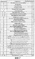
Фиг.7 показывает таблицу физической информации диска.7 shows a table of physical information of a disk.
Физическая информация диска кодируется в ADIP, как описано выше. Эта информация должна содержать 256 байтов, показанных на фиг.7. Она содержит информацию о диске и значения, используемые для алгоритма оптимального управления мощностью (OPC) для определения оптимального уровня мощности лазера для записи. Данная информация копируется в записываемую зону, которая называется "управляющими данными", во время инициализации диска. Содержимое этих данных следующее:Physical disk information is encoded in ADIP as described above. This information should contain 256 bytes, shown in Fig.7. It contains disk information and values used for the Optimal Power Management (OPC) algorithm to determine the optimal laser power level for recording. This information is copied to a recordable area called “control data” during disk initialization. The contents of this data are as follows:
Байт 0 - категория диска и номер версии. Биты b7-b4 должны определять категорию диска, они должны быть установлены в 1010, указывая диск DVD+R.Byte 0 - disk category and version number. Bits b7-b4 should determine the category of the disc, they should be set to 1010, indicating the disc DVD + R.
Биты b3-b0 должны определять номер версии, они должны быть установлены в 0000, указывая данную версию.Bits b3-b0 must determine the version number, they must be set to 0000, indicating this version.
Байт 1 - размер диска и максимальная скорость передачи.Byte 1 - disk size and maximum transfer rate.
Биты b7-b4 должны определять размер диска, они должны быть установлены в 0000, указывая на диск диаметром 120 мм.Bits b7-b4 should determine the size of the disk, they should be set to 0000, indicating a disk with a diameter of 120 mm.
Биты b3-b0 должны определять максимальную скорость передачи при чтении, они должны быть установлены в 1111, указывая, что максимальная скорость передачи при чтении не задана.Bits b3-b0 should determine the maximum reading baud rate, they should be set to 1111, indicating that the maximum reading baud rate was not set.
Байт 2 - структура диска.Byte 2 - disk structure.
Биты b7-b4 должны быть установлены в 0000.Bits b7-b4 must be set to 0000.
Биты b3-b0 определяют тип слоя (слоев) записи: они должны быть установлены в 0010, указывая слой записи с однократной записью.Bits b3-b0 determine the type of recording layer (s): they must be set to 0010, indicating a write-once recording layer.
Байт 3 - плотность записи.
Биты b7-b4 должны определять среднюю длину канального бита в информационной зоне, они должны быть установлены в 0000, указывая 0,133 мкм.Bits b7-b4 should determine the average length of the channel bit in the information area, they should be set to 0000, indicating 0.133 microns.
Биты b3-b0 должны определять средний шаг дорожки, они должны быть установлены в 0000, указывая средний шаг дорожки 0,74 мкм.Bits b3-b0 should determine the average pitch of the track, they should be set to 0000, indicating the average pitch of the track 0.74 μm.
Байты 4-15 - распределение зоны данных.Bytes 4-15 - data zone allocation.
Байт 4 должен быть установлен в (00).
Байты 5-7 должны быть установлены в (030000), определяя PSN 196608 первого физического сектора зоны данных.Bytes 5-7 should be set to (030000), defining PSN 196608 of the first physical sector of the data zone.
Байт 8 должен быть установлен в (00).
Байты 9-11 должны быть установлены в (26053F), определяя PSN 2491711 как последний возможный физический сектор зоны данных.Bytes 9-11 should be set to (26053F), defining PSN 2491711 as the last possible physical sector of the data zone.
Байты 12-15 должны быть установлены в (00).Bytes 12-15 should be set to (00).
Байт 16 - должен быть установлен в (00).Byte 16 - must be set to (00).
Байты 17-18 зарезервированы. Эти байты зарезервированы и должны быть установлены в (00).Bytes 17-18 are reserved. These bytes are reserved and must be set to (00).
Байты 19-26 - идентификатор изготовителя дисков. Эти 8 байтов должны идентифицировать изготовителя диска. Конечные, не используемые байты должны быть установлены в (00).Bytes 19-26 are the identifier of the disc manufacturer. These 8 bytes should identify the manufacturer of the disk. Trailing, unused bytes must be set to (00).
Байты 27-29 - идентификатор типа носителя. Изготовители дисков могут изготавливать различные типы носителей, которые должны определяться этими 3 байтами. Определенный тип диска обозначен в этом поле.Bytes 27-29 - media type identifier. Disc manufacturers can manufacture various types of media that must be specified by these 3 bytes. A specific type of disk is indicated in this field.
Байт 30 - номер версии изделия. Этот байт должен идентифицировать номер версии изделия в двоичном виде. Все диски с тем же самым идентификатором изготовителя диска и тем же самым идентификатором изделия, независимо от номера версии изделия, должны иметь те же самые свойства записи (допускаются только незначительные различия: номера версии изделия должны быть несущественны для записывающих устройств). Если не используется, то этот байт должен быть установлен в (00).
Байт 31 - количество используемых байтов информации физического формата. Этот байт формирует одно 8-битное двоичное число, указывающее количество байтов, фактически используемое для информации физического формата. Он должен быть установлен в (36), указывая, что используются только первые 54 байта информации физического формата.
Байт 32 - базовая скорость записи. Этот байт указывает самую низкую возможную скорость записи диска, которая упоминается также как базовая скорость, как число n, такое, что
n=10×Vref n = 10 × V ref
(n округляется к целому значению). Он должен быть установлен в (23), указывая базовую скорость записи 3,49 м/с.(n is rounded to an integer value). It should be set to (23), indicating a base recording speed of 3.49 m / s.
Байт 33 - максимальная скорость записи. Этот байт указывает самую высокую возможную скорость записи диска, как число n, такое, что
n=10×Vref n = 10 × V ref
(n округляется к целому значению). Он должен быть установлен в (54), указывая максимальную скорость записи 8,44 м/с.(n is rounded to an integer value). It should be set to (54), indicating a maximum recording speed of 8.44 m / s.
Байт 34 - длина волны λIND. Этот байт должен определять длину волны лазера в нанометрах, с которой оптимальные параметры записи в следующих байтах были определены, как число n, такое, что n=длина волны - 600.
Байт 35 зарезервирован.
Байт 36 - максимальная мощность Pr считывания при базовой скорости. Этот байт должен определять максимальную мощность Pr считывания в милливаттах при базовой скорости как число n, такое, что
n=20×(Pr-0,7).n = 20 × (Pr-0.7).
Байт 37 - PIND при базовой скорости. PIND - начальное значение для определения Ppo, используемого в алгоритме OPC. Этот байт должен определять показательное значение PIND Ppo в милливаттах при базовой скорости как число n, такое, чтоByte 37 - PIND at base speed. PIND is the initial value for determining the Ppo used in the OPC algorithm. This byte should determine the exponent PIND Ppo in milliwatts at the base speed as a number n, such that
n=20×(PIND-5).n = 20 × (P IND -5).
Байт 38 - βtarget при базовой скорости. Этот байт должен определять целевое значение для β, βtarget при базовой скорости, используемое в алгоритме OPC как число n, такое, чтоByte 38 - β target at base speed. This byte should determine the target value for β, β target at the base speed, used in the OPC algorithm as the number n, such that
n=10×βtarget. n = 10 × β target.
Байт 39 - максимальная мощность считывания, Pr при максимальной скорости. Этот байт должен определять максимальную мощность Pr считывания в милливаттах при максимальной скорости как число n, такое, что
n=20×(Pr-0,7).n = 20 × (Pr-0.7).
Байт 40 - PIND при максимальной скорости. PIND - начальное значение для определения Ppo, используемого в алгоритме OPC. Этот байт должен определять показательное значение PIND Ppo в милливаттах при максимальной скорости как число n, такое, чтоByte 40 - PIND at maximum speed. PIND is the initial value for determining the Ppo used in the OPC algorithm. This byte should determine the exponent PIND Ppo in milliwatts at maximum speed as a number n such that
n=20×(PIND-5).n = 20 × (PIND-5).
Байт 41 - βtarget при максимальной скорости. Этот байт должен определять целевое значение для β, βtarget при максимальной скорости, используемой в алгоритме OPC, как число n, такое, чтоByte 41 - β target at maximum speed. This byte should determine the target value for β, β target at the maximum speed used in the OPC algorithm, as the number n, such that
n=10×βtarget.n = 10 × β target .
Байт 42 - Ttop (≥4) длительность первого импульса для текущей метки (ТМ) ≥4 при базовой скорости. Этот байт должен определять длительность первого импульса последовательности импульсов, когда текущей меткой является метка 4T или большая метка для записи при базовой скорости. Значение выражено в долях тактового периода канального бита как число n, такое, что![]()
![]()
Байт 43 - Ttop (=3) длительность первого импульса для текущей метки =3 при базовой скорости. Этот байт должен определять длительность первого импульса последовательности импульсов, когда текущей меткой является метка 3T для записи при базовой скорости. Значение выражено в долях тактового периода канального бита как число n, такое, чтоByte 43 - Ttop (= 3) the duration of the first pulse for the current label = 3 at base speed. This byte should determine the duration of the first pulse of the pulse train when the current mark is a 3T mark for recording at base speed. The value is expressed in fractions of the clock period of the channel bit as the number n, such that
![]()
![]()
Байт 44 - Tmp длительность последовательности импульсов при базовой скорости. Этот байт должен определять длительность с 2-ого импульса по последний импульс последовательности импульсов для записи при базовой скорости. Значение выражено в долях тактового периода канального бита как число n, такое, чтоByte 44 - Tmp the duration of the pulse sequence at the base speed. This byte should determine the duration from the 2nd pulse to the last pulse of the pulse train for recording at base speed. The value is expressed in fractions of the clock period of the channel bit as the number n, such that
![]()
![]()
Байт 45 - Tlp длительность последнего импульса при базовой скорости. Этот байт должен определять длительность последнего импульса последовательности импульсов для записи при базовой скорости. Значение выражено в долях тактового периода канального бита как число n, такое, чтоByte 45 - Tlp last pulse duration at base speed. This byte should determine the duration of the last pulse of the pulse train to record at base speed. The value is expressed in fractions of the clock period of the channel bit as the number n, such that
![]()
![]()
Байт 46 - dTtop опережение первого импульса при базовой скорости. Этот байт должен определять опережение первого импульса последовательности импульсов относительно заднего фронта второго канального бита импульса данных для записи при базовой скорости. Значение выражено в долях тактового периода канального бита как число n, такое, чтоByte 46 - dTtop leading the first pulse at the base speed. This byte should determine the advance of the first pulse of the pulse train relative to the trailing edge of the second channel bit of the data pulse for recording at the base speed. The value is expressed in fractions of the clock period of the channel bit as the number n, such that
![]()
![]()
Байт 47 - dTle коррекция переднего фронта первого импульса для предыдущего пробела (отсутствия сигнала) (ПОС)=3 при базовой скорости. Биты 7-4 из этого байта должны определять коррекцию переднего фронта для 1-ого импульса последовательности импульсов, когда предыдущий пробел был пробелом 3T для записи при базовой скорости. Значение выражено в долях тактового периода канального бита в соответствии с фиг.8.Byte 47 - dTle correction of the leading edge of the first pulse for the previous space (no signal) (PIC) = 3 at the base speed. Bits 7-4 from this byte should determine the leading edge correction for the 1st pulse of the pulse train when the previous space was a 3T space for recording at base speed. The value is expressed in fractions of the clock period of the channel bit in accordance with Fig.
Байт 48 - Ttop (≥4) длительность первого импульса для текущей метки ≥4 при максимальной скорости. Этот байт должен определять длительность первого импульса последовательности импульсов, когда текущая метка является меткой 4T или большей меткой для записи при максимальной скорости. Значение выражено в долях тактового периода канального бита как число n, такое, чтоByte 48 - Ttop (≥4) the duration of the first pulse for the current label ≥4 at maximum speed. This byte should determine the duration of the first pulse of the pulse train when the current mark is a 4T mark or a larger mark for recording at maximum speed. The value is expressed in fractions of the clock period of the channel bit as the number n, such that
![]()
![]()
Байт 49 - Ttop (3) длительность первого импульса для текущей метки =3 при максимальной скорости. Этот байт должен определять длительность первого импульса последовательности импульсов, когда текущая метка является меткой 3T для записи при максимальной скорости. Значение выражено в долях тактового периода канального бита как число n, такое, чтоByte 49 - Ttop (3) the duration of the first pulse for the current label = 3 at maximum speed. This byte should determine the duration of the first pulse of the pulse train when the current mark is a 3T mark for recording at maximum speed. The value is expressed in fractions of the clock period of the channel bit as the number n, such that
![]()
![]()
Байт 50 - Tmp длительность последовательности импульсов при максимальной скорости. Этот байт должен определять длительность со 2-ого импульса до последнего импульса последовательности импульсов для записи при максимальной скорости. Значение выражено в долях тактового периода канального бита как число n, такое, чтоByte 50 - Tmp pulse train duration at maximum speed. This byte should determine the duration from the 2nd pulse to the last pulse of the pulse train for recording at maximum speed. The value is expressed in fractions of the clock period of the channel bit as the number n, such that
![]()
![]()
Байт 51 - Tlp длительность последнего импульса при максимальной скорости. Этот байт должен определять длительность последнего импульса последовательности импульсов для записи при максимальной скорости. Значение выражено в долях тактового периода канального бита как число n, такое, чтоByte 51 - Tlp last pulse duration at maximum speed. This byte should determine the duration of the last pulse of the pulse train to record at maximum speed. The value is expressed in fractions of the clock period of the channel bit as the number n, such that
![]()
![]()
Байт 52 - dTtop опережение первого импульса при максимальной скорости. Этот байт должен определять опережение первого импульса последовательности импульсов относительно заднего фронта второго канального бита импульса данных для записи при максимальной скорости. Значение выражено в долях тактового периода канального бита как число n, такое, чтоByte 52 - dTtop ahead of the first pulse at maximum speed. This byte should determine the advance of the first pulse of the pulse train relative to the trailing edge of the second channel bit of the data pulse for recording at maximum speed. The value is expressed in fractions of the clock period of the channel bit as the number n, such that
![]()
![]()
Байт 53 - dTle коррекция переднего фронта первого импульса для предыдущего пробела =3 при максимальной скорости. Биты 7-4 из этого байта должны определять коррекцию переднего фронта для 1-ого импульса последовательности импульсов, когда предыдущий пробел был пробелом 3T для записи при максимальной скорости. Значение выражено в долях тактового периода канального бита согласно фиг.8.Byte 53 - dTle correction of the leading edge of the first pulse for the previous space = 3 at maximum speed. Bits 7-4 from this byte should determine the leading edge correction for the 1st pulse of the pulse train when the previous space was a 3T space for recording at maximum speed. The value is expressed in fractions of the clock period of the channel bit according to Fig.
Байты 54-255 зарезервированы - все (00). Все эти байты должны быть установлены в (00).Bytes 54-255 are reserved - all (00). All these bytes must be set to (00).
Фиг.8 показывает времена коррекции переднего фронта. Параметр называют dTle и он описан выше на фиг.7 в байте 47. Биты с 3 по 0 этого байта должны быть установлены в 0000. Неуказанные комбинации разрядов не должны использоваться.Fig. 8 shows leading edge correction times. The parameter is called dTle and it is described above in FIG. 7 in
Фиг.9 показывает нумерацию секторов носителя информации. Область записи называют информационной зоной. Информационная зона должна содержать всю информацию на диске, значимую для обмена данными. Информационная зона может содержать одну или более сессий. Каждая сессия должна быть разделена на три части: вводная зона/зона открытия, зона данных и выводная зона/зона закрытия. На двусторонних дисках существует одна информационная зона на каждой стороне. Зоны данных предназначены для записи пользовательских данных. Вводная зона содержит информацию управления. Выводная зона делает возможным непрерывный плавный вывод и также содержит информацию управления. Внутренняя и внешняя области диска предназначены для тестирования диска. Описание дается для односессионного диска. В таком диске вводная зона, зона данных и выводная зона составляют область записи, в которой информация записывается, используя необратимый эффект. Структура многосессионного диска будет определена позже.Fig.9 shows the numbering of sectors of the information carrier. The recording area is called an information zone. The information zone should contain all the information on the disk that is significant for data exchange. An information zone may contain one or more sessions. Each session should be divided into three parts: the introductory zone / opening zone, the data zone and the lead-out zone / closing zone. On double-sided discs, there is one information zone on each side. Data zones are for recording user data. The introductory area contains control information. The exit zone enables continuous, smooth output and also contains control information. The internal and external areas of the disc are for testing the disc. Description is for a single session disc. In such a disc, an input zone, a data zone and an output zone constitute a recording area in which information is recorded using an irreversible effect. The structure of the multisession disc will be determined later.
Фиг.10 показывает структуру записываемого односессионного диска. Информационная зона односторонних дисков и каждой стороны двусторонних дисков подразделяется на внутреннюю область диска, вводную зону, зону данных, выводную зону и внешнюю область диска. Радиусы указаны для зон с помощью номинальных значений центра первой (или последней) дорожки зоны. Номера физических секторов (PSN) показывают первый физический сектор каждой зоны. Зона данных должна иметь первый PSN (030000). Номера PSN увеличиваются на 1 для каждого следующего физического сектора во всей информационной зоне.Figure 10 shows the structure of a recordable single-session disc. The information area of single-sided disks and each side of double-sided disks is subdivided into the internal area of the disk, the input area, the data area, the output area and the external area of the disk. Radii are indicated for zones using the nominal values of the center of the first (or last) track of the zone. Physical sector numbers (PSNs) indicate the first physical sector of each zone. The data zone must have the first PSN (030000). PSNs are incremented by 1 for each subsequent physical sector in the entire information area.
Фиг.11 показывает внутреннюю область диска. Внутренняя область диска - самая внутренняя зона диска, которая используется диском для выполнения тестирования диска и алгоритмов OPC. Номер физического сектора первого и последнего физического сектора каждой части указан в шестнадцатеричном и десятичном представлении, а количество физических секторов в каждой части обозначено в десятичном виде. Показано следующее разделение:11 shows an inner region of a disc. The inner area of the disk is the innermost area of the disk that the disk uses to perform disk testing and OPC algorithms. The physical sector number of the first and last physical sectors of each part is indicated in hexadecimal and decimal, and the number of physical sectors in each part is indicated in decimal. The following separation is shown:
- Начальная зона: эта зона должна оставаться пустой.- Initial zone: this zone should remain empty.
- Внутренняя зона тестирования диска: 16384 физических сектора, которые зарезервированы для тестирования диска и OPC.- Internal disk testing zone: 16384 physical sectors that are reserved for disk testing and OPC.
- Внутренняя зона счетчика диска: 4096 физических секторов, зарезервированных для подсчета количества алгоритмов OPC, выполненных во внутренней зоне тестирования диска. Всякий раз, когда блок ECC или его часть записываются во внутренней зоне тестирования диска, блок ECC должен быть помечен с помощью записи 4 физических секторов во внутренней зоне счетчика диска.- Internal area of the disk counter: 4096 physical sectors reserved for counting the number of OPC algorithms performed in the internal area of the disk test. Whenever an ECC block or part thereof is recorded in the internal area of a disc test, the ECC unit must be marked by recording 4 physical sectors in the internal area of the disc counter.
- Внутренняя зона администрирования диска: 4096 физических секторов, которые используются для необязательной специфической для диска информации. Первые 16 физических секторов этой зоны должны быть заполнены основными данными, установленными в (00). Внутренняя зона администрирования диска содержит информацию о диске, например идентификатор диска (ID диска), и данные, которые определяются изготовителем диска.- Internal disk administration area: 4096 physical sectors that are used for optional disk-specific information. The first 16 physical sectors of this zone should be filled with the basic data set in (00). The internal disk administration area contains disk information, such as a disk identifier (disk ID), and data that is determined by the manufacturer of the disk.
- Зона оглавления (TOC): 4096 физических секторов для хранения информации о расположении сессий и записей на диске. Первые 16 физических секторов этой зоны должны быть заполнены основными данными, установленными в (00). Эта зона состоит из 2 частей:- Table of Contents Zone (TOC): 4096 physical sectors for storing session and disc location information. The first 16 physical sectors of this zone should be filled with the basic data set in (00). This zone consists of 2 parts:
часть 1: состоит из 191 блоков ECC (блоков TOC), которые используются для хранения расположения всех закрытых сессий,part 1: consists of 191 ECC blocks (TOC blocks), which are used to store the location of all closed sessions,
часть 2: состоит из 1024 физических секторов, сгруппированных в элементы из 4 секторов, причем каждый элемент соответствует одному слову ADIP. Эти элементы должны использоваться в качестве индикаторов области записи.part 2: consists of 1024 physical sectors grouped into elements of 4 sectors, each element corresponding to one ADIP word. These elements should be used as indicators of the recording area.
Фиг.12 показывает формат блока TOC. Всякий раз, когда сессия закрывается, следующий блок ECC должен записываться в зоне оглавления сразу после последнего блока TOC с расположением всех закрытых сессий. Первый блок ECC в зоне оглавления должен использоваться в качестве входного для второго блока ECC. Если все 191 блоков TOC использовались, то дополнительные сессии все еще можно добавить, однако диску придется применять процедуру поиска для того, чтобы найти дополнительные сессии. Данная фигура показывает следующее содержимое блока TOC для каждого физического сектора:12 shows a TOC block format. Whenever a session closes, the next ECC block should be recorded in the table of contents right after the last TOC block with all closed sessions located. The first ECC block in the table of contents should be used as input to the second ECC block. If all 191 TOC blocks were used, then additional sessions can still be added, however, the disk will have to use the search procedure in order to find additional sessions. This figure shows the following contents of the TOC block for each physical sector:
Физический сектор 0/байты D0-D3 - описатель содержимого. Эти байты идентифицируют сессию DCB и должны быть установлены в (544F4300), представляя символы "SDC" и номер версии 0.
Физический сектор 0/байты D4-D7 - зарезервированы. Должны быть установлены в (00).
Физический сектор 0/байты D8-D39 - идентификатор диска. Эти байты должны содержать идентификатор диска.
Физический сектор 0/байты D40-D63 - зарезервированы. Должны быть установлены в (00).
Физический сектор 0/байты D64-D2047 - элементы сессии. Эти байты сгруппированы в модулях по 16 байтов каждый. Каждый модуль из 16 байтов может содержать элемент сессии согласно фиг.13. Все неиспользуемые байты должны быть установлены в (00).
Фиг.13 показывает элемент сессии. Блок TOC должен содержать элемент сессии для каждой закрытой сессии на диске. Элементы сессии должны упорядочиваться по увеличению чисел и адресов следующим образом:13 shows a session item. The TOC block must contain a session element for each closed session on disk. Session elements should be ordered by increasing numbers and addresses as follows:
байты B0-B2: эти 3 байта идентифицируют тип элемента и должны быть установлены в (53.53.4E), представляя символы "SSN";Bytes B0-B2: These 3 bytes identify the type of item and should be set to (53.53.4E), representing the characters "SSN";
байт B3: этот байт должен определять порядковый номер сессии, указанной в этом элементе;byte B3: this byte should determine the sequence number of the session specified in this element;
байты B4-B7: эти 4 байта должны определять PSN первого физического сектора в зоне данных сессии, указанной в этом элементе;Bytes B4-B7: These 4 bytes should determine the PSN of the first physical sector in the session data area specified in this element;
байты B8-B11: эти 4 байта должны определять PSN последнего физического сектора в зоне данных сессии, указанной в этом элементе;Bytes B8-B11: These 4 bytes should determine the PSN of the last physical sector in the session data area specified in this element;
байты B12-B15: эти 4 байта зарезервированы и должны быть установлены в (00).Bytes B12-B15: These 4 bytes are reserved and must be set to (00).
Фиг.14 показывает индикаторы области записи (RAI). Последняя часть зоны TOC для записи блоков 61 TOC показана схематично. Область 60 отображения расположена в конце зоны TOC. Следующая зона, т.е. зона 62 защиты, показана с правой стороны. Область отображения записывают, начиная с самого старшего адреса. Записанная часть 64 указывает записанные секции области записи, а незаписанная часть 63 указывает незаписанные секции. Чтобы ускорить доступ к диску, устройство записи должно знать, в какой секции диска последний записанный блок ECC может быть найден. Для этой цели определяется область отображения, основываясь на записанных областях, размером в 4 физических сектора, причем каждая область соответствует одному слову ADIP. Эти области должны быть записаны с помощью случайных сигналов кода EFM (кодирование 8 к 14). Никакие промежутки не позволяются между записываемыми словами ADIP. 1024 физических сектора зарезервированы для этой цели, позволяя делить диск максимально на 256 секций. Индикаторы области записи должны использоваться от внешней стороны зоны TOC к внутренней стороне зоны TOC. С помощью "высокочастотного обнаружения" устройство записи может найти расположение начала индикаторов области записи и определить секцию, в которой может быть найден последний записанный блок ECC. Каждая секция из 640 блоков ECC между PSN=(030000) и PSN=(26053F) соответствует одному индикатору области записи. Все секции вплоть до последнего записанного блока ECC включительно должны быть обозначены своим индикатором области записи. В математической форме: если первый индикатор области записи составлен из физических секторов с PSNRAI по PSNRAI +3, тогда последний записанный блок ECC может быть найден между:14 shows indicators of a recording area (RAI). The last part of the TOC zone for recording TOC blocks 61 is shown schematically. A
PSN={(02A47C)-(PSNRAI)}×(A0)+(030000) иPSN = {(02A47C) - (PSNRAI)} × (A0) + (030000) and
PSN={(02A47C)-(PSNRAI)}×(A0)+(030280)PSN = {(02A47C) - (PSNRAI)} × (A0) + (030280)
или в десятичном представлении:or in decimal notation:
PSN={173180-PSNRAI}×160+196608 иPSN = {173180-PSNRAI} × 160 + 196608 and
PSN={173180-PSNRAI}×160+197248PSN = {173180-PSNRAI} × 160 + 197248
В варианте осуществления устройства блок 32 обнаружения сконфигурирован для логарифмического поиска области отображения посредством итерационного обнаружения высокочастотных сигналов по проверяемому адресу, который находится в 50% от непроверенной части области отображения, причем область отображения имеет одну записанную часть, указывающую на последовательно записанные секции. Когда метки не обнаружены по проверяемому адресу, тогда следующий проверяемый адрес располагают в 50% от непроверенного адресного интервала по направлению к началу области отображения, и наоборот.Оставшийся непроверенный интервал адресов можно исследовать непрерывно, когда указанный оставшийся непроверенным интервал адресов станет настолько малым, что переход к логарифмическому определению адреса потребовал бы больше времени. Подобный процесс поиска может использоваться для обнаружения самого старшего записанного адреса в пределах секции.In an embodiment of the device, the
Фиг.15 показывает вводную зону. Вводная зона расположена с внутренней стороны информационной зоны. Неиспользованный диск не имеет никаких данных, записанных во вводной зоне. После завершения диска или закрытия первой сессии должна записываться вводная зона, как описано ниже. Фиг.15 показывает зоны и адреса следующим образом (примечания, как для фиг.11):15 shows an introduction zone. The introductory area is located on the inside of the information area. An unused disc does not have any data recorded in the introductory area. After completing the disc or closing the first session, an introductory area should be recorded as described below. Fig. 15 shows zones and addresses as follows (notes, as for Fig. 11):
- Зона защиты 1: зона защиты используется для создания минимального объема вводной зоны, требуемой для совместимости. Эта зона должна содержать 14848 физических секторов, заполненных основными данными, установленными в (00).- Protection Zone 1: The protection zone is used to create the minimum introductory area required for compatibility. This zone should contain 14848 physical sectors filled with basic data set in (00).
- Зарезервированная зона 1: 4096 физических секторов зарезервированы и должны быть установлены в (00).- Reserved zone 1: 4096 physical sectors are reserved and must be set to (00).
- Зарезервированная зона 2: 64 физических сектора зарезервированы и должны быть установлены в (00).- Reserved zone 2: 64 physical sectors are reserved and must be set to (00).
- Внутренняя зона идентификации диска: 256 физических секторов, зарезервированных для информации, согласованной сторонами, которые обмениваются данными. Каждый набор из 16 физических секторов из одного блока ECC является или управляющим блоком диска (DCB), или записан основными данными со всеми (00). Каждый блок ECC в этой зоне, следующий после блока, записанного основными данными со всеми (00), должен также записываться основными данными со всеми (00).- Internal disk identification zone: 256 physical sectors reserved for information agreed by the parties that exchange data. Each set of 16 physical sectors from one ECC block is either a disk control unit (DCB), or is recorded with basic data with all (00). Each ECC block in this zone, following the block recorded by the master data with all (00), must also be recorded by the master data with all (00).
- Зарезервированная зона 3: 64 физических сектора зарезервированы и должны быть установлены в (00).- Reserved zone 3: 64 physical sectors are reserved and must be set to (00).
- Зона эталонного кода: записанная зона эталонного кода должна состоять из 32 физических секторов двух блоков ECC, которые генерируют определенную комбинацию канальных битов на диске. Это должно быть достигнуто, устанавливая в значение (AC) все 2048 байтов основных данных каждого соответствующего кадра данных. Кроме того, скремблирование не должно применяться к этим кадрам данных, за исключением первых 160 байтов основных данных первого кадра данных каждого блока ECC.- Reference Code Zone: The recorded reference code zone should consist of 32 physical sectors of two ECC blocks that generate a specific combination of channel bits on the disk. This must be achieved by setting to (AC) all 2048 bytes of the main data of each corresponding data frame. In addition, scrambling should not be applied to these data frames, with the exception of the first 160 bytes of the main data of the first data frame of each ECC block.
- Буферная зона 1: эта зона должна состоять из 480 физических секторов из 30 блоков ECC. Все основные данные кадров данных в этой зоне должны быть установлены в (00).- Buffer zone 1: this zone should consist of 480 physical sectors of 30 ECC blocks. All master data data frames in this zone must be set to (00).
- Зона управляющих данных: эта зона должна состоять из 3072 физических секторов из 192 блоков ECC. Содержимое 16 физических секторов каждого блока ECC повторяется 192 раза.- Management data zone: this zone should consist of 3072 physical sectors of 192 ECC blocks. The contents of 16 physical sectors of each ECC block are repeated 192 times.
- Буферная зона 2: эта записанная зона должна состоять из 512 физических секторов из 32 блоков ECC. Все основные данные кадров данных в этой зоны должны быть установлены в (00).- Buffer Zone 2: This recorded zone should consist of 512 physical sectors of 32 ECC blocks. All master data frame data in this zone must be set to (00).
Фиг.16 показывает структуру блока управляющих данных. Первые 2048 байтов составляют информацию физического формата, содержимое которой показано на фиг.7. Следующие 2048 байтов составляет информация производителя диска. Последний 14 x 2048 байтов доступны для информации поставщика контента (информационно значимого наполнения). В варианте осуществления устройства 28672 байта информации поставщика контента установлены в ноль (00). Данные, принимаемые от главного компьютера, блокируются и не записываются в это поле. Это предохраняет записываемые в него данные конфиденциального характера, например ключи расшифровки для декодирования видеоинформации видеодиска DVD. Информация физического формата содержит информацию о формате и диске. Информация в байтах от 0 до 255 должна копироваться со вспомогательных данных ADIP во время завершения диска или закрытия первой сессии и должна отражать фактическое состояние диска или первой сессии (например, фактический конец зоны данных). Все 256 байтов имеют такое же описание и содержимое, как информация физического диска, описанная на фиг.7, кроме следующих байтов:16 shows a structure of a control data block. The first 2048 bytes constitute physical format information, the contents of which are shown in FIG. The following 2048 bytes is information about the manufacturer of the disk. The last 14 x 2048 bytes are available for content provider information (content). In an embodiment of the device, 28672 bytes of content provider information are set to zero (00). Data received from the host computer is blocked and not written to this field. This protects confidential data recorded in it, for example, decryption keys for decoding video information of a DVD video disc. Physical format information contains format and disk information. Information in bytes from 0 to 255 should be copied from the auxiliary ADIP data during the completion of the disk or the closure of the first session and should reflect the actual state of the disk or the first session (for example, the actual end of the data zone). All 256 bytes have the same description and contents as the physical disk information described in FIG. 7, except for the following bytes:
Байт 0 - категория диска и номер версии.Byte 0 - disk category and version number.
Биты b7-b4 должны определять категорию диска, указывая на DVD+R диск.Bits b7-b4 should identify the category of the disc, indicating the DVD + R disc.
Биты b3-b0 должны определять номер версии системного описания.Bits b3-b0 must determine the version number of the system description.
Байт 1 - устанавливает размеры диска и максимальную скорость передачи.Byte 1 - sets the disk size and maximum transfer rate.
Биты b7-b4 должны определять размер диска, они должны быть установлены в 0000, указывая на диск 120 мм.Bits b7-b4 should determine the size of the disk, they should be set to 0000, indicating a 120 mm disk.
Биты b3-b0 должны определять максимальную скорость передачи при считывании.Bits b3-b0 should determine the maximum bit rate when reading.
Эти биты могут быть установлены в одно из следующих значений, в зависимости от максимальной скорости считывания, необходимой приложениям:These bits can be set to one of the following values, depending on the maximum read speed required by the applications:
0000: максимальная скорость передачи 2,52 Мбит/с;0000: maximum transfer rate 2.52 Mbps;
0001: максимальная скорость передачи 5,04 Мбит/с;0001: maximum transfer rate of 5.04 Mbps;
0010: максимальная скорость передачи 10,08 Мбит/с;0010: maximum bit rate 10.08 Mbps;
1111: максимальная скорость передачи не определена.1111: maximum baud rate not defined.
Все другие комбинации зарезервированы и не должны использоваться.All other combinations are reserved and should not be used.
Байт 2 - структура диска.Byte 2 - disk structure.
Биты b7-b4 должны быть установлены в 0000.Bits b7-b4 must be set to 0000.
Биты b3-b0 должны определять тип слоя (слоев) записи: они должны быть установлены в 0010, указывая слой записи с однократной записью.Bits b3-b0 must determine the type of recording layer (s): they must be set to 0010, indicating a write-once recording layer.
Байты 4-15 - распределение зоны данных.Bytes 4-15 - data zone allocation.
Байт 4 должен быть установлен в (00).
Байты 5-7 должны быть установлены в (030000), чтобы определять номер физического сектора (PSN), равный 196608, для первого физического сектора зоны данных.Bytes 5-7 must be set to (030000) to determine the physical sector number (PSN) of 196608 for the first physical sector of the data zone.
Байт 8 должен быть установлен в (00).
Байты 9-11 должны определять номер последнего физического сектора зоны данных для первой сессии.Bytes 9-11 should determine the number of the last physical sector of the data zone for the first session.
Байты 12-15 должны быть установлены в (00).Bytes 12-15 should be set to (00).
Байты 256-2047 - зарезервированы. Эти оставшиеся байты не имеют никакого отношения к информации ADIP и должны быть установлены в ноль (00).Bytes 256-2047 are reserved. These remaining bytes have nothing to do with ADIP information and should be set to zero (00).
Фиг.17 показывает выводную зону. Наверху показана зона 70 данных, предназначенная для записи пользовательских данных. Зона данных имеет 2295104 физических секторов области пользовательских данных. Радиус начала зоны данных определяется физическим адресом ADIP (00C000). После зоны данных следует выводная зона. Выводная зона расположена с внешней стороны информационной зоны. Фиг.17 показывает следующие части:17 shows an exit zone. Above is a
- Буферная зона 3: эта записываемая зона должна состоять из 768 физических секторов. Последний возможный адрес начала буферной зоны 3 - (260540). Все основные данные кадров данных в этой зоне должны быть установлены в (00).- Buffer Zone 3: This recordable zone should consist of 768 physical sectors. The last possible address for the start of
- Внешняя зона идентификации диска: 256 физических секторов, зарезервированных для информации, согласованной по условию обменивающимися сторонами. Каждый набор из 16 физических секторов одного блока ECC является или управляющим блоком диска (DCB), или записывается основными данными, равными (00). Содержимое этой зоны должно быть эквивалентно содержимому последней внутренней зоны идентификации сессии (или содержимому внутренней зоны идентификации диска в случае односессионного диска).- External disk identification zone: 256 physical sectors reserved for information agreed upon by the exchanging parties. Each set of 16 physical sectors of one ECC block is either a disk control unit (DCB), or is written with basic data equal to (00). The contents of this zone should be equivalent to the contents of the last internal session identification zone (or the contents of the internal disk identification zone in the case of a single-session disk).
- Зона защиты 2: данная зона защиты используется в качестве защиты для отделения записываемой зоны тестирования от информационных зон, содержащих пользовательские данные. Эта зона должна быть заполнена основными данными, установленными в (00). Эта зона должна содержать как минимум 4096 физических секторов.- Protection zone 2: this protection zone is used as protection to separate the recorded test zone from information zones containing user data. This zone must be filled with the basic data set in (00). This zone must contain at least 4096 physical sectors.
- Внешняя область диска: внешняя область диска - наиболее удаленная зона диска, которая используется диском для выполнения тестов диска и алгоритмов OPC.- External disk area: the external disk area is the most remote disk area that the disk uses to perform disk tests and OPC algorithms.
Фиг.18 показывает внешнюю область диска, начиная с зоны защиты 2. Показаны следующие части:Fig. 18 shows an outer region of a disk starting from
- Внешняя зона администрирования диска: 4096 физических секторов, которые используются для необязательной специфической для диска информации. Первые 16 физических секторов этой зоны должны быть заполнены основными данными, которые все установлены в (00). Эта зона может использоваться тем же самым способом, как внутренняя зона администрирования диска (см. 0).- External disk administration zone: 4096 physical sectors that are used for optional disk-specific information. The first 16 physical sectors of this zone should be filled with basic data, which are all set to (00). This zone can be used in the same way as the internal disk administration zone (see 0).
- Внешняя зона счетчика диска: 4096 физических секторов, зарезервированных для подсчета количества алгоритмов OPC, выполненных во внешней зоне тестирования диска.- External area of the disk counter: 4096 physical sectors reserved for counting the number of OPC algorithms performed in the external area of the disk test.
- Внешняя зона тестирования диска: 16384 физических сектора, зарезервированные для тестирования диска и алгоритмов OPC. Всякий раз, когда блок ECC или его часть записывается во внешней зоне тестирования диска, блок ECC должен быть помечен посредством записи 4 физических секторов во внешней зоне счетчика диска.- External disk testing zone: 16384 physical sectors reserved for disk testing and OPC algorithms. Whenever an ECC block or part of it is recorded in the external area of a disc test, the ECC unit must be marked by recording 4 physical sectors in the external area of the disc counter.
- Зона защиты 3: эта зона должна оставаться пустой.- Protection zone 3: this area must remain empty.
Хотя данное изобретение объяснялось главным образом с помощью вариантов осуществления, используя DVD+R, подобные варианты осуществления подходят для других оптических систем записи. Также в качестве носителя информации был описан оптический диск, но могут использоваться другие носители, такие как магнитный диск или лента. Следует отметить, что в этом документе слово "содержит" не исключает присутствия других элементов или этапов, кроме перечисленных, и описание элемента в единственном числе не исключает присутствия множества таких элементов, что любые упоминаемые обозначения не ограничивают объем формулы изобретения, что изобретение может быть осуществлено и с помощью аппаратных средств, и с помощью программного обеспечения, и что некоторые "средства" могут быть представлены одним и тем же элементом аппаратных средств. Дополнительно, объем изобретения не ограничен вариантами осуществления, и изобретение заключается в каждом новом признаке или комбинации признаков, описанных выше.Although the invention has been explained mainly with the help of embodiments using DVD + R, similar embodiments are suitable for other optical recording systems. An optical disk has also been described as a storage medium, but other media such as a magnetic disk or tape may be used. It should be noted that in this document the word “contains” does not exclude the presence of other elements or steps other than those listed, and the description of the element in the singular does not exclude the presence of a plurality of such elements, that any notation mentioned does not limit the scope of the claims that the invention may be practiced and with the help of hardware, and with the help of software, and that some "tools" can be represented by the same element of hardware. Additionally, the scope of the invention is not limited to the embodiments, and the invention lies in each new feature or combination of features described above.
Claims (12)
Applications Claiming Priority (5)
| Application Number | Priority Date | Filing Date | Title |
|---|---|---|---|
| EP01201480.9 | 2001-04-24 | ||
| EP01201480 | 2001-04-24 | ||
| EP0275706.8 | 2002-02-21 | ||
| EP02075706 | 2002-02-21 | ||
| EP02075706.8 | 2002-02-21 |
Publications (2)
| Publication Number | Publication Date |
|---|---|
| RU2003133984A RU2003133984A (en) | 2005-02-27 |
| RU2287863C2 true RU2287863C2 (en) | 2006-11-20 |
Family
ID=26076885
Family Applications (1)
| Application Number | Title | Priority Date | Filing Date |
|---|---|---|---|
| RU2003133984/28A RU2287863C2 (en) | 2001-04-24 | 2002-04-18 | Representation of consecutive sections for information blocks |
Country Status (19)
| Country | Link |
|---|---|
| US (2) | US6785196B2 (en) |
| EP (1) | EP1386236B1 (en) |
| JP (1) | JP5112598B2 (en) |
| KR (1) | KR100914642B1 (en) |
| CN (1) | CN1245690C (en) |
| AR (1) | AR035865A1 (en) |
| AT (1) | ATE355559T1 (en) |
| BR (1) | BRPI0205082B1 (en) |
| CA (1) | CA2414791C (en) |
| CY (1) | CY1106618T1 (en) |
| DE (1) | DE60218448T2 (en) |
| DK (1) | DK1386236T3 (en) |
| ES (1) | ES2281512T3 (en) |
| MX (1) | MXPA03000162A (en) |
| PL (1) | PL231541B1 (en) |
| PT (1) | PT1386236E (en) |
| RU (1) | RU2287863C2 (en) |
| TW (1) | TWI226610B (en) |
| WO (1) | WO2002086731A1 (en) |
Cited By (1)
| Publication number | Priority date | Publication date | Assignee | Title |
|---|---|---|---|---|
| RU2468421C2 (en) * | 2007-03-30 | 2012-11-27 | Майкрософт Корпорейшн | Technique for sharing information between applications |
Families Citing this family (19)
| Publication number | Priority date | Publication date | Assignee | Title |
|---|---|---|---|---|
| CA2478533C (en) * | 2002-03-05 | 2013-02-05 | Koninklijke Philips Electronics N.V. | Device, record carrier and method for recording information |
| CA2483163C (en) * | 2002-04-24 | 2011-11-01 | Samsung Electronics Co., Ltd. | Optical information storage medium and method of recording thereon |
| AU2003250557A1 (en) * | 2002-07-31 | 2004-02-16 | Samsung Electronics Co., Ltd. | Information storage medium and method of recording information thereon |
| MXPA05001297A (en) | 2002-08-03 | 2005-04-28 | Samsung Electronics Co Ltd | Information storage medium and method of recording and/or reproducing with respect to the medium. |
| KR100750109B1 (en) * | 2003-02-15 | 2007-08-21 | 삼성전자주식회사 | Information storage medium |
| US7496017B2 (en) * | 2003-05-09 | 2009-02-24 | Koninklijke Philips Electronics N.V. | Method for formatting an optical disc |
| DE04747473T1 (en) | 2003-07-08 | 2006-11-30 | Matsushita Electric Industrial Co., Ltd., Kadoma | RETRIEVABLE RECORDING MEDIUM, RECORDING METHOD, RECORDING DEVICE, PLAYING METHOD AND PLAYING DEVICE |
| KR20050028396A (en) * | 2003-09-17 | 2005-03-23 | 삼성전자주식회사 | Method of recording data using multi-session, and the information storage medium therefor |
| TWI245281B (en) * | 2004-03-19 | 2005-12-11 | Benq Corp | Method and apparatus for recording data into optical disks |
| US7916582B2 (en) * | 2004-05-11 | 2011-03-29 | Samsung Electronics Co., Ltd. | Optical recording medium, recording/reproducing apparatus and method, initialization method, and reinitialization method |
| JP4058020B2 (en) | 2004-05-14 | 2008-03-05 | 株式会社東芝 | Optical disc recording / reproducing method, recording / reproducing apparatus, and optical disc |
| US7663990B2 (en) * | 2004-05-21 | 2010-02-16 | Samsung Electronics Co., Ltd. | Optical recording medium having access control area and method for recording or reproducing thereof |
| US7907160B2 (en) * | 2004-07-23 | 2011-03-15 | Hewlett-Packard Development Company, L.P. | Track labeling on a medium |
| JP4660217B2 (en) * | 2005-01-31 | 2011-03-30 | 株式会社東芝 | Storage medium, reproducing method, recording method, reproducing apparatus and recording apparatus |
| TW200709185A (en) * | 2005-08-26 | 2007-03-01 | Benq Corp | Method for testing DVD+R dual layer disc and apparatus therefor |
| WO2007032506A1 (en) * | 2005-09-15 | 2007-03-22 | Ricoh Company, Ltd. | Optical recording medium and optical recording apparatus |
| KR101365447B1 (en) * | 2006-09-04 | 2014-02-19 | 삼성전자주식회사 | Information recording medium, and recording reproducing apparatus |
| KR101292728B1 (en) * | 2006-11-17 | 2013-08-01 | 삼성전자주식회사 | Optical recording medium, Optical recording medium manufacturing apparatus and method therefor, and recording/reproducing apparatus and method therefor |
| JP2021140835A (en) * | 2020-03-02 | 2021-09-16 | 株式会社東芝 | Magnetic disk device |
Family Cites Families (16)
| Publication number | Priority date | Publication date | Assignee | Title |
|---|---|---|---|---|
| US512496A (en) * | 1894-01-09 | Histological case | ||
| JPS63104284A (en) * | 1986-10-21 | 1988-05-09 | Mitsubishi Electric Corp | Disk file access system |
| US5124966A (en) * | 1989-03-29 | 1992-06-23 | U.S. Philips Corporation | Method for recording data signals on an inscribable record carrier and reading device for the record carrier |
| JPH043368A (en) * | 1990-04-20 | 1992-01-08 | Sony Corp | Optical disk |
| JPH04106761A (en) | 1990-08-28 | 1992-04-08 | Matsushita Electric Ind Co Ltd | Information recording and reproducing device and optical disk |
| US5341356A (en) | 1991-04-02 | 1994-08-23 | U.S. Philips Corporation | Method and device for recording information volumes in a track of a record carrier, and a device for reading the record carrier |
| JPH05101544A (en) * | 1991-10-07 | 1993-04-23 | Pioneer Electron Corp | Method for recording on draw type optical disk and recorder for draw type optical disk and optical disk |
| DE69721718T2 (en) * | 1996-09-03 | 2004-03-11 | Koninklijke Philips Electronics N.V. | INFORMATION CARRIER, READING / WRITING DEVICE AND READING DEVICE FOR READING AND / OR WRITING INFORMATION BLOCKS |
| US6269338B1 (en) | 1996-10-10 | 2001-07-31 | U.S. Philips Corporation | Data compression and expansion of an audio signal |
| CN1126102C (en) * | 1996-11-18 | 2003-10-29 | 皇家菲利浦电子有限公司 | Writing device, record carrier and method of writing information blocks, and reading device for reading information blocks |
| EP0880780B1 (en) * | 1996-11-18 | 2004-04-28 | Philips Electronics N.V. | Writing device, record carrier and writing method, and reading device for reading information blocks |
| JP3855390B2 (en) * | 1997-09-16 | 2006-12-06 | ソニー株式会社 | Recording apparatus, recording method, and disk-shaped recording medium |
| CN100514484C (en) * | 1998-06-09 | 2009-07-15 | 索尼株式会社 | Reproducing apparatus, reproducing method |
| DE19859845A1 (en) * | 1998-12-23 | 2000-06-29 | Thomson Brandt Gmbh | Playback device for record carriers containing information blocks |
| DE60237079D1 (en) * | 2001-04-24 | 2010-09-02 | Koninkl Philips Electronics Nv | DEVICE AND METHOD FOR INFORMATION RECORDING |
| PL366405A1 (en) * | 2001-04-24 | 2005-01-24 | Koninklijke Philips Electronics N.V. | Device and method for recording information |
-
2002
- 2002-04-18 DK DK02724540T patent/DK1386236T3/en active
- 2002-04-18 ES ES02724540T patent/ES2281512T3/en not_active Expired - Lifetime
- 2002-04-18 JP JP2002584182A patent/JP5112598B2/en not_active Expired - Lifetime
- 2002-04-18 DE DE60218448T patent/DE60218448T2/en not_active Expired - Lifetime
- 2002-04-18 PT PT02724540T patent/PT1386236E/en unknown
- 2002-04-18 BR BRPI0205082-0A patent/BRPI0205082B1/en active IP Right Grant
- 2002-04-18 CN CNB028021614A patent/CN1245690C/en not_active Expired - Lifetime
- 2002-04-18 AT AT02724540T patent/ATE355559T1/en active
- 2002-04-18 EP EP02724540A patent/EP1386236B1/en not_active Expired - Lifetime
- 2002-04-18 CA CA2414791A patent/CA2414791C/en not_active Expired - Lifetime
- 2002-04-18 WO PCT/IB2002/001414 patent/WO2002086731A1/en active IP Right Grant
- 2002-04-18 MX MXPA03000162A patent/MXPA03000162A/en active IP Right Grant
- 2002-04-18 KR KR1020027017518A patent/KR100914642B1/en active IP Right Grant
- 2002-04-18 RU RU2003133984/28A patent/RU2287863C2/en active
- 2002-04-18 PL PL364385A patent/PL231541B1/en unknown
- 2002-04-24 AR ARP020101485A patent/AR035865A1/en active IP Right Grant
- 2002-04-24 US US10/128,835 patent/US6785196B2/en not_active Expired - Lifetime
- 2002-05-31 TW TW091111696A patent/TWI226610B/en not_active IP Right Cessation
-
2004
- 2004-04-26 US US10/832,173 patent/US7057980B2/en not_active Expired - Lifetime
-
2007
- 2007-05-23 CY CY20071100699T patent/CY1106618T1/en unknown
Cited By (1)
| Publication number | Priority date | Publication date | Assignee | Title |
|---|---|---|---|---|
| RU2468421C2 (en) * | 2007-03-30 | 2012-11-27 | Майкрософт Корпорейшн | Technique for sharing information between applications |
Also Published As
| Publication number | Publication date |
|---|---|
| BRPI0205082B1 (en) | 2015-07-14 |
| CA2414791C (en) | 2012-09-18 |
| PL231541B1 (en) | 2019-03-29 |
| ATE355559T1 (en) | 2006-03-15 |
| TWI226610B (en) | 2005-01-11 |
| CN1245690C (en) | 2006-03-15 |
| DK1386236T3 (en) | 2007-06-18 |
| EP1386236A1 (en) | 2004-02-04 |
| PT1386236E (en) | 2007-06-01 |
| WO2002086731A1 (en) | 2002-10-31 |
| DE60218448T2 (en) | 2007-10-31 |
| KR100914642B1 (en) | 2009-08-28 |
| KR20030011101A (en) | 2003-02-06 |
| ES2281512T3 (en) | 2007-10-01 |
| JP2004528668A (en) | 2004-09-16 |
| JP5112598B2 (en) | 2013-01-09 |
| BR0205082A (en) | 2003-04-29 |
| DE60218448D1 (en) | 2007-04-12 |
| US6785196B2 (en) | 2004-08-31 |
| CY1106618T1 (en) | 2012-01-25 |
| AR035865A1 (en) | 2004-07-21 |
| EP1386236B1 (en) | 2007-02-28 |
| PL364385A1 (en) | 2004-12-13 |
| RU2003133984A (en) | 2005-02-27 |
| US20040196748A1 (en) | 2004-10-07 |
| US7057980B2 (en) | 2006-06-06 |
| CA2414791A1 (en) | 2002-10-31 |
| CN1463400A (en) | 2003-12-24 |
| US20030012088A1 (en) | 2003-01-16 |
| MXPA03000162A (en) | 2003-05-27 |
Similar Documents
| Publication | Publication Date | Title |
|---|---|---|
| RU2297678C2 (en) | Device and method for recording information | |
| JP4190892B2 (en) | Apparatus and method for recording information | |
| RU2287863C2 (en) | Representation of consecutive sections for information blocks | |
| JP4920871B2 (en) | Information recording apparatus, record carrier, and method |