RU2281811C2 - Foam generator - Google Patents
Foam generator Download PDFInfo
- Publication number
- RU2281811C2 RU2281811C2 RU2003118438/12A RU2003118438A RU2281811C2 RU 2281811 C2 RU2281811 C2 RU 2281811C2 RU 2003118438/12 A RU2003118438/12 A RU 2003118438/12A RU 2003118438 A RU2003118438 A RU 2003118438A RU 2281811 C2 RU2281811 C2 RU 2281811C2
- Authority
- RU
- Russia
- Prior art keywords
- pump
- liquid
- inlet
- foaming device
- outlet
- Prior art date
Links
Images

Classifications
-
- B—PERFORMING OPERATIONS; TRANSPORTING
- B05—SPRAYING OR ATOMISING IN GENERAL; APPLYING FLUENT MATERIALS TO SURFACES, IN GENERAL
- B05B—SPRAYING APPARATUS; ATOMISING APPARATUS; NOZZLES
- B05B7/00—Spraying apparatus for discharge of liquids or other fluent materials from two or more sources, e.g. of liquid and air, of powder and gas
- B05B7/0018—Spraying apparatus for discharge of liquids or other fluent materials from two or more sources, e.g. of liquid and air, of powder and gas with devices for making foam
- B05B7/0025—Spraying apparatus for discharge of liquids or other fluent materials from two or more sources, e.g. of liquid and air, of powder and gas with devices for making foam with a compressed gas supply
-
- B—PERFORMING OPERATIONS; TRANSPORTING
- B05—SPRAYING OR ATOMISING IN GENERAL; APPLYING FLUENT MATERIALS TO SURFACES, IN GENERAL
- B05B—SPRAYING APPARATUS; ATOMISING APPARATUS; NOZZLES
- B05B11/00—Single-unit hand-held apparatus in which flow of contents is produced by the muscular force of the operator at the moment of use
- B05B11/01—Single-unit hand-held apparatus in which flow of contents is produced by the muscular force of the operator at the moment of use characterised by the means producing the flow
- B05B11/10—Pump arrangements for transferring the contents from the container to a pump chamber by a sucking effect and forcing the contents out through the dispensing nozzle
- B05B11/1042—Components or details
- B05B11/1073—Springs
- B05B11/1074—Springs located outside pump chambers
-
- B—PERFORMING OPERATIONS; TRANSPORTING
- B05—SPRAYING OR ATOMISING IN GENERAL; APPLYING FLUENT MATERIALS TO SURFACES, IN GENERAL
- B05B—SPRAYING APPARATUS; ATOMISING APPARATUS; NOZZLES
- B05B11/00—Single-unit hand-held apparatus in which flow of contents is produced by the muscular force of the operator at the moment of use
- B05B11/01—Single-unit hand-held apparatus in which flow of contents is produced by the muscular force of the operator at the moment of use characterised by the means producing the flow
- B05B11/10—Pump arrangements for transferring the contents from the container to a pump chamber by a sucking effect and forcing the contents out through the dispensing nozzle
- B05B11/1087—Combination of liquid and air pumps
Landscapes
- Closures For Containers (AREA)
- Containers And Packaging Bodies Having A Special Means To Remove Contents (AREA)
- Absorbent Articles And Supports Therefor (AREA)
- Separation By Low-Temperature Treatments (AREA)
- Reciprocating Pumps (AREA)
- Liquid Developers In Electrophotography (AREA)
- Glass Compositions (AREA)
- Insulated Conductors (AREA)
- Superconductors And Manufacturing Methods Therefor (AREA)
Abstract
Description
Изобретение относится к пенообразующему устройству для использования в сочетании с сосудом для жидкости, содержащему воздушный насос и насос для жидкости.The invention relates to a foaming device for use in combination with a liquid vessel comprising an air pump and a liquid pump.
Такое пенообразующее устройство известно, например, из международной заявки на патент WO-A-99/54054, в которой описано устройство для распыления пены для сосуда с жидкостью, имеющее часть для всасывания воздуха, камеру смешения и распылительную головку с выходом для пены. Первый блок поршень-цилиндр для воздуха и второй блок поршень-цилиндр для жидкости предусмотрены между распылительной головкой и резервуаром для жидкости. К каждому блоку пригнан входной и выходной клапан. Эти блоки соединены таким образом, что они взаимодействуют друг с другом.Such a foaming device is known, for example, from international patent application WO-A-99/54054, which describes a device for spraying foam for a vessel with a liquid, having a part for sucking air, a mixing chamber and a spray head with a foam outlet. A first piston-cylinder block for air and a second piston-cylinder block for liquid are provided between the spray head and the liquid reservoir. An inlet and outlet valve is fitted to each block. These blocks are connected in such a way that they interact with each other.
В еще одной международной заявке на патент WO 97/13585 описано устройство для выдачи пены, которое содержит резервуар для жидкости и приводящийся в действие блок из концентричных воздушного насоса и насоса для жидкости. Каждый насос имеет поршневую камеру с поршнем, который может перемещаться в ней, а также вход и выход. Приводящий в действие компонент приводит в действие оба насоса одновременно. Воздушный насос имеет выключающее устройство двойного действия, которое может активно приводиться в действие приводящим в действие компонентом и выключает как вход, так и выход воздуха. В этом документе точно упомянуто, что обычные клапаны, как пассивные выключающие устройства, которые открываются под действием разностей давления, создаваемых в блоке, нежелательны, и выключающее устройство, которое может активно приводиться в действие посредством приводящего в действие компонента, является основной характеристикой этого пенообразующего устройства. Более того, хотя это пенообразующее устройство может вырабатывать хорошую пену, т.е. пену правильной текстуры, это известное пенообразующее устройство состоит из большого числа конструктивных компонентов, изготовленных из различных материалов. Стоимость изготовления такого пенообразующего устройства, следовательно, относительно высока.Another international patent application WO 97/13585 describes a foam dispenser that comprises a fluid reservoir and an actuated unit of a concentric air pump and a fluid pump. Each pump has a piston chamber with a piston that can move in it, as well as an input and output. The driving component drives both pumps simultaneously. The air pump has a double-acting switching device that can be actively driven by the driving component and turns off both the air inlet and the outlet. This document explicitly mentions that conventional valves, like passive switch-off devices that open under the pressure differences created in the unit, are undesirable, and a switch-off device that can be actively driven by the actuation component is the main characteristic of this foaming device . Moreover, although this foaming device can produce good foam, i.e. foam of the correct texture, this known foaming device consists of a large number of structural components made of various materials. The manufacturing cost of such a foaming device is therefore relatively high.
Далее, в US-A-4057176 описан пальцевый насос возвратно-поступательного типа для использования в резервуаре для жидких продуктов, который объединяет трубчатый корпус, включающий распылительное сопло, смонтированное коаксиально во втулке крышки сборника, включающей центральный клапан. Отверстие клапана ведет к погружной трубе, которая проходит в резервуар. Если трубчатый корпус сжимается, полый поршень приводится в действие от растяжения пружины. Для того чтобы обеспечить аэрозольное распыление, требуется два последовательных хода вниз. Этот насос сконструирован только для того, чтобы распылять жидкость, хотя другие продукты типа газов, паров или порошков могут быть распылены. Однако он не может создавать пену, как в настоящем изобретении.Further, US-A-4057176 describes a finger type reciprocating pump for use in a liquid product reservoir that integrates a tubular body including a spray nozzle mounted coaxially in a collector cover sleeve including a central valve. The valve opening leads to an immersion pipe that extends into the reservoir. If the tubular body is compressed, the hollow piston is actuated by stretching the spring. In order to provide aerosol spraying, two consecutive downward strokes are required. This pump is designed only to spray liquid, although other products such as gases, vapors or powders can be sprayed. However, it cannot create foam, as in the present invention.
Технической задачей настоящего изобретения является усовершенствование пенообразующего устройства по известному уровню техники.An object of the present invention is to improve a foaming device according to the prior art.
С этой целью пенообразующее устройство в соответствии с изобретением отличается признаками по п.1 формулы изобретения. Путем объединения взаимосвязанных функций всех элементов в единую, образованную как одно целое часть, число элементов конструкции может быть уменьшено, что приводит в результате к более низкой стоимости изготовления.To this end, the foaming device in accordance with the invention is distinguished by the features according to
Дополнительные преимущества настоящего изобретения могут быть ясны из зависимых пунктов формулы изобретения.Further advantages of the present invention may be apparent from the dependent claims.
Далее изобретение дополнительно будет разъяснено со ссылками на прилагаемые чертежи, иллюстрирующие пример настоящего изобретения, и на которых:The invention will be further explained below with reference to the accompanying drawings, illustrating an example of the present invention, and in which:
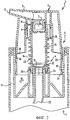
фиг.1 - перспективный вид в разрезе пенообразующего устройства в соответствии с изобретением,figure 1 is a perspective view in section of a foaming device in accordance with the invention,
фиг.2 - разрез пенообразующего устройства по фиг.1 в первом крайнем положении,figure 2 is a section of the foaming device of figure 1 in the first extreme position,
фиг.3 - разрез пенообразующего устройства по фиг.1 во втором крайнем положении, иfigure 3 is a section of the foaming device of figure 1 in the second extreme position, and
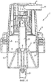
фиг.4 - разрез пенообразующего устройства в соответствии с изобретением по другому конструктивному исполнению.figure 4 is a section of a foaming device in accordance with the invention according to another design.
Одинаковые номера позиций использованы на каждой из этих фигур для аналогичных элементов конструкции.The same item numbers are used on each of these figures for similar structural elements.
На перспективном виде в разрезе на фиг.1 изображено устройство для выдачи пены, состоящее из резервуара 1 для жидкости и пенообразующего устройства 2. Пенообразующее устройство 2 содержит воздушный насос 3 и насос 4 для жидкости, в каждом из которых предусмотрен вход и выход. Вход воздушного насоса 3 соединен с окружающей средой, в то время как вход насоса 4 для жидкости соединен с содержимым резервуара 1 для жидкости. Пенообразующее устройство 2 дополнительно содержит камеру 5 смешения, которая соединена с выходом как воздушного насоса 3, так и насоса 4 для жидкости.In a perspective view in section, figure 1 shows a device for dispensing foam, consisting of a
На верхней части устройства расположена часть для выдачи, одновременно являющаяся исполнительным органом 6, в которой предусмотрен выходной канал 7 с отверстием 8 для пены. Выходной канал 7 проходит от камеры 5 смешения до отверстия 8 для пены. Один или более элементов для образования пены обычно размещены в этом канале 7.On the upper part of the device there is a part for dispensing, which at the same time is an executive body 6, in which an
Как вход, так и выход каждого насоса 3, 4 снабжены клапанами соответственно 9, 10, 11, 12 для подачи соответственно всасываемого воздуха или жидкости. Клапан 12 на входе насоса 4 для жидкости показан только на фиг.2 и 3.Both the inlet and outlet of each
Насос 4 для жидкости содержит камеру 13 повышенного давления, образованную полым цилиндрическим поршнем 14, который может перемещаться относительно внутренней части элемента 17 держателя, в котором установлен клапан 12. Другими словами, термин «поршень» понимается, как обозначение такой части насоса, которая перемещается (сравнить с фиг.2 и фиг.4). Камера 13 повышенного давления, таким образом, расположена между входным клапаном 12, выходным клапаном 11 и поршнем 14 насоса 4 для жидкости. Кроме того, воздушный насос 3 содержит камеру 15 повышенного давления, образованную полым цилиндрическим поршнем 16, который может перемещаться относительно наружной части цилиндрического элемента 17 держателя. Камера 15 повышенного давления воздушного насоса 3 связана на одной стороне с входным клапаном 10 и выходным клапаном 9 и на другой стороне между поршнями 14, 16 двух насосов 3, 4 и элементом 17 держателя. Эти полые цилиндрические поршни расположены концентрично относительно друг друга.The
Исполнительный орган 6 для того, чтобы приводить в действие два насоса 3, 4, изготовлен как единое целое с поршнем 16 воздушного насоса 3. Исполнительный орган 6, или поршень 16 воздушного насоса 3, выполнены с возможностью скольжения в элементе 17 держателя, который удерживает пенообразующее устройство 2 в резервуаре 1 для жидкости. При перемещении исполнительного органа 6 это движение передается непосредственно на поршень 16, чтобы привести в действие воздушный насос 3. Когда перемещается исполнительный орган 6, насос 4 для жидкости также приводится в действие, так как соединительный элемент 18 размещен между исполнительным органом 6 и поршнем 14 насоса 4 для жидкости, причем этот соединительный элемент передает перемещение исполнительного органа 6 к поршню 14 насоса 4 для жидкости.The actuator 6, in order to drive the two
На фиг.1 ясно показано, что клапаны 9, 10, 11 образованы мембранами заданной толщины, образованными на конструктивных элементах 14. При толщине стенки конструктивных элементов 14 и 18 примерно 1 мм толщина цилиндрических мембран 9 и 11 составляет, например, 0,2 мм. Клапаны 9, 10, 11 выполнены инжекционным формованием из пластика, аналогичного пластику воздушного насоса 3 или насоса 4 для жидкости, чтобы образовать единый элемент 14, 18 конструкции, т.е. как одну часть из той же самой пластмассы. Для понимания настоящего изобретения необходимо отметить, что соединительный элемент 18 считается частью воздушного насоса 3.Figure 1 clearly shows that the
Соединительный элемент 18 имеет на одной стороне направленный к исполнительному органу 6 выступ 27 с двумя круглыми седлами 28, 29 различного диаметра. В этих седлах помещены один или более пенообразующих элементов, например, в форме сит с мелкими отверстиями (не показаны). В конструктивном исполнении на фиг.4 пенообразующий элемент аналогично расположен в выступе 27 соединительного элемента 18, но в этом случае он образован стенкой с отверстиями 30, которая совместно отливается при литье под давлением соединительного элемента 18. Для хорошего пенообразования отверстия имеют максимальный диаметр примерно 0,2 мм, стенка, в которой они расположены, имеет толщину примерно 0,2 мм, и стенка содержит от 100 до 200 отверстий, предпочтительно примерно 150 отверстий. Эти технические условия могут быть использованы в разумных пределах аналогичным способом в пенообразующих устройствах для косметической продукции.The connecting
Во втором конструктивном исполнении пенообразующего устройства 2, показанном на фиг.4, выходной клапан 11 насоса 4 для жидкости образован отдельным коническим упором, который взаимодействует с верхней кромкой поршня 14. На упоре 11 имеется стержень 31, который находится в контакте со стенкой с отверстиями 30. Посредством выбора размеров и выбора материала этот пенообразующий элемент 30 приобретает определенную упругость, так что под влиянием повышения давления в камере 13 повышенного давления, передаваемого через упор 11 и стержень 31, он может деформироваться. Пенообразующий элемент 30 поэтому служит, прежде всего, вместе со стержнем 31 для того, чтобы закрывать клапан 11. Когда давление в камере 13 станет больше, чем сопротивление пенообразующего элемента 30, клапан будет открыт.In the second embodiment of the
Отверстие 19 для аэрации дополнительно размещено в элементе 17 держателя для пополнения резервуара 1 для жидкости воздухом из окружающей среды, когда жидкость откачивается из резервуара для выдачи пены. В крайнем положении, в котором нет давления (смотри фиг.2), устройства для выдачи пены отверстие 19 для аэрации расположено между двумя уплотнительными буртиками 20, 21 поршня 16 для воздуха. Эти уплотнительные буртики 20, 21 обеспечивают, чтобы в положении, показанном на фиг.2, жидкость не могла выйти наружу, когда агрегат удерживается перевернутым вверх дном относительно своего положения. Во втором крайнем положении, показанном на фиг.3, воздух снаружи может проходить в резервуар 1 для жидкости для пополнения воздуха в резервуаре 1.The
Положения, показанные на фиг.2 и 3, представляют собой два крайних положения устройства. Между этими двумя положениями образован ход соответственно в направлении вниз (из положения на фиг.2 в положение на фиг.3) и в направлении вверх (из положения на фиг.3 в положение на фиг.2). Ход вверх представляет собой ход для всасывания, в котором воздух, а также жидкость всасываются в соответствующие камеры 13, 15 повышенного давления, в то время как ход вниз представляет собой ход для подачи, в котором воздух и жидкость нагнетаются из камер 13, 15 повышенного давления в камеру 5 смешения.The positions shown in FIGS. 2 and 3 are two extreme positions of the device. Between these two positions, a stroke is formed, respectively, in the downward direction (from the position in FIG. 2 to the position in FIG. 3) and in the upward direction (from the position in FIG. 3 to the position in FIG. 2). The upstroke is a suction stroke in which air as well as liquid is sucked into the
Работа пенообразующего устройства описана со ссылками на фиг.2 и 3, начиная с фиг.3. Исполнительный орган 6 (и поршень воздушного насоса), соединительный элемент 18 и поршень 14 насоса для жидкости образуют одно целое в продолжение работы устройства для выдачи пены и поэтому обозначены ниже общим одним термином «поршень». Между поршнем 14, 16, 18 и элементом 17 держателя расположена пружина 22, которая не нагружена в положении, показанном на фиг.2.The operation of the foaming device is described with reference to figure 2 and 3, starting with figure 3. The actuator 6 (and the piston of the air pump), the connecting
На фиг.3 поршень 14, 16, 18 находится в положении сжатия и находится в точке, в которой он испытывает давление вверх от силы пружины, создаваемой пружиной 22. В продолжение хода вверх объем камеры 15 повышенного давления воздушного насоса 3 становится больше, посредством чего давление становится ниже, чем давление окружающей среды. Благодаря этой разнице в давлении входной клапан 10 воздушного насоса 3 открывается, и устанавливается соединение между окружающей средой и камерой 15 повышенного давления воздуха. То же самое относится к объему в камере 13 повышенного давления насоса 4 для жидкости. Здесь также объем увеличивается, посредством чего давление падает, и жидкость вытесняется из резервуара 1 для жидкости через стояк 23. Всасывание жидкости через входной клапан 12 возможно, потому что поршень 14 для жидкости с уплотнительными буртиками 24, 25, расположенными на нем, перемещается вниз, и создается проход между входным клапаном 12 и поршнем 14 в камеру 13 повышенного давления.In figure 3, the
Насос теперь находится в самом верхнем положении (фиг.2), посредством чего как камера 15 повышенного давления воздуха, так и камера 13 повышенного давления жидкости заполнены соответственно воздухом и жидкостью. Когда направленная вниз сила, которая теперь создается на поршне 14, 16, 18, больше, чем сила пружины, создаваемая пружиной 22, плюс силы трения между поршнем 14, 16, 18 и элементом 17 держателя, поршень 14, 16, 18 переместится вниз. Объем в камере 15 повышенного давления воздуха уменьшается, и давление, следовательно, увеличивается, посредством чего входной клапан 10, который был открыт при ходе вверх, теперь закрыт под давлением, в то время как выходной клапан 9 открыт. То же относится к объему в камере 13 повышенного давления жидкости, в которой входной клапан 12 прижат к седлу посредством повышения давления для того, чтобы закрыть вход насоса 4 для жидкости. Кроме того, входной клапан 11 насоса 4 для жидкости открывается посредством повышенного давления в камере 13 повышенного давления жидкости.The pump is now in the uppermost position (FIG. 2), whereby both the
Воздух и жидкость поступают вместе в камеру 5 смешения. Так как поток воздуха и поток жидкости сталкиваются друг с другом, они хорошо перемешиваются. После того как смесь проходит через один или более пенообразующих элементов, создается пена, которая через выходной канал 7 выходит через отверстие 8 для пены части для выдачи агрегата. Сопротивление мембраны 11 в конструктивном исполнении, показанном на фиг.1-3, и стенки с отверстиями как пенообразующего элемента 30 в конструктивном исполнении по фиг.4 обеспечивает, чтобы жидкость не проходила свободно из насоса 4 для жидкости. Поток жидкости в камере 5 смешения контролируется и управляется здесь. Испытания показали, что это является существенным для получения хорошей пены.Air and liquid enter together into the mixing
Так как входной клапан 12 снабжен корпусом упора, который взаимодействует с уплотнительными буртиками 24, 25, размещенными в поршне 14, дополнительно создается жидкостный затвор. Это означает, что в положении покоя (фиг.2) обеспечивается, чтобы жидкость не выходила из устройства или не входила в полость между поршнем 14, 16, 18 и элементом 17 держателя, когда давление в резервуаре 1 повышается, например, потому что резервуар сжимается. Когда давление в резервуаре 1 для жидкости повышается, корпус 12 упора прижимается к уплотнительному буртику 25 и, таким образом, прекращает проход жидкости в любую из камер 13, 15 повышенного давления.Since the
Элемент 17 держателя снабжен рядом периферических сегментов, обозначенных позицией 26, для того чтобы ограничить ход поршня 14, 16, 18 относительно камер 13, 15 повышенного давления. Эти периферические сегменты находятся в первом приближении на одной линии с цилиндрической нижней стенкой элемента 17 держателя, т.е. отлиты под давлением в этом положении вместе с элементом 17 держателя и изогнуты в продолжение монтажа агрегата для выдачи пены. В продолжение монтажа элемент 17 держателя зажимается или завинчивается на резервуар 1 для жидкости, после чего поршень 14, 16, 18 помещается на элемент 17 держателя, и периферические сегменты 26 загибаются внутрь.The
Настоящее изобретение, конечно, не ограничено предпочтительными конструктивными исполнениями, показанными на чертежах. Хотя насосы 3, 4 показаны как концентрические, также возможно разместить их эксцентрично или примыкающими друг к другу. Пример такой конструкции можно найти в международной заявке на патент WO 99/54054. Кроме того, также возможно, например, выполнить входной клапан 12 насоса 4 для жидкости как мембрану, образованную на поршне 14 или элементе 18 держателя, посредством чего жидкостный затвор может быть создан другим способом. В любом случае здесь создается в соответствии с изобретением упрощенное пенообразующее устройство с относительно небольшим числом конструктивных компонентов.The present invention, of course, is not limited to the preferred designs shown in the drawings. Although
Claims (11)
Applications Claiming Priority (2)
| Application Number | Priority Date | Filing Date | Title |
|---|---|---|---|
| NL1016694A NL1016694C2 (en) | 2000-11-23 | 2000-11-23 | Foam forming unit. |
| NL1016694 | 2000-11-23 |
Publications (2)
| Publication Number | Publication Date |
|---|---|
| RU2003118438A RU2003118438A (en) | 2004-12-10 |
| RU2281811C2 true RU2281811C2 (en) | 2006-08-20 |
Family
ID=19772452
Family Applications (1)
| Application Number | Title | Priority Date | Filing Date |
|---|---|---|---|
| RU2003118438/12A RU2281811C2 (en) | 2000-11-23 | 2001-11-23 | Foam generator |
Country Status (19)
| Country | Link |
|---|---|
| US (1) | US7147133B2 (en) |
| EP (1) | EP1343593B1 (en) |
| JP (1) | JP3999658B2 (en) |
| KR (1) | KR100886335B1 (en) |
| CN (1) | CN1263551C (en) |
| AT (1) | ATE342775T1 (en) |
| AU (2) | AU2279802A (en) |
| BR (1) | BR0115603B1 (en) |
| CA (1) | CA2429685C (en) |
| CY (1) | CY1106265T1 (en) |
| DE (1) | DE60124002T2 (en) |
| DK (1) | DK1343593T3 (en) |
| ES (1) | ES2272574T3 (en) |
| HK (1) | HK1062155A1 (en) |
| MX (1) | MXPA03004585A (en) |
| NL (1) | NL1016694C2 (en) |
| PT (1) | PT1343593E (en) |
| RU (1) | RU2281811C2 (en) |
| WO (1) | WO2002042005A1 (en) |
Families Citing this family (41)
| Publication number | Priority date | Publication date | Assignee | Title |
|---|---|---|---|---|
| US6923346B2 (en) * | 2002-11-06 | 2005-08-02 | Continental Afa Dispensing Company | Foaming liquid dispenser |
| NL1024350C2 (en) | 2003-09-23 | 2005-03-24 | R & D Injector Ag | Delivery unit for concentrated injection. |
| US7802701B2 (en) * | 2005-01-14 | 2010-09-28 | Rieke Corporation | Up-lock seal for dispenser pump |
| NL1030030C2 (en) | 2005-04-20 | 2006-10-23 | Keltec B V | Dispensing unit with improved supply shut-off means. |
| CN100571893C (en) * | 2005-04-20 | 2009-12-23 | Kel技术有限公司 | Have the distributor that improves supply-closing means |
| NL1028921C2 (en) * | 2005-04-29 | 2006-11-01 | Airspray Nv | Dispensing device. |
| US7337930B2 (en) * | 2005-05-20 | 2008-03-04 | Gotohti.Com Inc. | Foaming pump with improved air inlet valve |
| CN2839636Y (en) * | 2005-08-30 | 2006-11-22 | 林添大 | Foam pump |
| NL1030361C2 (en) * | 2005-11-07 | 2007-05-08 | Keltec B V | Dispensing unit with improved air supply. |
| NL1030992C2 (en) * | 2006-01-24 | 2007-07-26 | Airspray Nv | Squeeze foamer. |
| US7819289B2 (en) * | 2006-04-14 | 2010-10-26 | Joseph S Kanfer | Foam soap generator |
| GB2437510A (en) * | 2006-04-26 | 2007-10-31 | Packaging Innovation Ltd | Dispenser mechanism |
| US7735688B2 (en) * | 2006-10-10 | 2010-06-15 | Meadwestvaco Calmar, Inc. | Rotating collar and locking and venting closure connector for an air foaming pump dispenser |
| US7735692B2 (en) * | 2006-10-10 | 2010-06-15 | Meadwestvaco Calmar, Inc. | Rotating dispenser head with locking and venting closure connector for an air foaming pump dispenser |
| US8544698B2 (en) * | 2007-03-26 | 2013-10-01 | Gojo Industries, Inc. | Foam soap dispenser with stationary dispensing tube |
| JP4998943B2 (en) * | 2007-05-31 | 2012-08-15 | 株式会社吉野工業所 | Bubble jet |
| CN201073625Y (en) * | 2007-08-10 | 2008-06-18 | 屠旭峰 | Spume pump |
| CA2699737A1 (en) * | 2007-09-21 | 2009-03-26 | Packaging Innovation Limited | Dispenser mechanism |
| US20090107579A1 (en) * | 2007-10-26 | 2009-04-30 | Smith Robin E | Loading system |
| KR101408641B1 (en) * | 2007-11-01 | 2014-06-17 | 주식회사 종우실업 | Foam Production Pump Not Causing Contamination of Contents |
| US8056768B2 (en) * | 2007-12-28 | 2011-11-15 | Snodgrass David L | Foam pump assembly |
| JP4979602B2 (en) * | 2008-01-18 | 2012-07-18 | 株式会社Lixil | Soap dispenser |
| US7850049B2 (en) * | 2008-01-24 | 2010-12-14 | Gojo Industries, Inc. | Foam pump with improved piston structure |
| JP5348994B2 (en) * | 2008-10-10 | 2013-11-20 | 株式会社Lixil | Soap dispenser |
| US8286836B2 (en) * | 2008-10-14 | 2012-10-16 | Gojo Industries, Inc. | Dispensing tube assembly and foam generator for coaxial tubes |
| CN201292924Y (en) * | 2008-11-06 | 2009-08-19 | 屠旭峰 | Foam pump |
| EP2544662B1 (en) | 2010-03-10 | 2020-05-20 | Nuvo Pharmaceuticals Inc. | Foamable formulation |
| US8360283B1 (en) | 2011-08-17 | 2013-01-29 | Zhejiang JM Industry Co., Ltd | Liquid foaming pump |
| US9066636B2 (en) | 2012-06-26 | 2015-06-30 | Gojo Industries, Inc. | Grit and foam dispenser |
| NL2009085C2 (en) * | 2012-06-29 | 2013-12-31 | Rexam Airspray Nv | Foam dispensing assembly. |
| US8678241B2 (en) * | 2012-08-27 | 2014-03-25 | Ya-Tsan Wang | Foam spray head assembly |
| GB2506182B (en) * | 2012-09-25 | 2018-05-30 | Derjin Hong Kong Holding Company Ltd | Lotion spray head assembly |
| FR3001719B1 (en) * | 2013-02-07 | 2016-02-05 | Gb Dev | FLUID DISPENSING DEVICE AND METHOD FOR MANUFACTURING SUCH A DEVICE. |
| AU2014291498B2 (en) * | 2013-07-17 | 2016-12-22 | Yoshino Kogyosho Co., Ltd. | Foamer dispenser, and container with foamer dispenser |
| US20160121351A1 (en) * | 2014-11-04 | 2016-05-05 | Gojo Industries, Inc. | Double acting bladder pump |
| NL2015694B1 (en) * | 2015-10-30 | 2017-05-31 | Dispensing Tech Bv | System and method for dispensing a liquid foam, in particular a direct-foam cleaning product. |
| NL2015724B1 (en) | 2015-11-04 | 2017-05-24 | Gab Eng & Dev B V | Storage holder for a dispenser. |
| NL2016644B1 (en) | 2016-04-20 | 2017-11-07 | Gab Eng & Development B V | Storage holder for a dispenser |
| CN107628355B (en) * | 2016-07-19 | 2023-05-26 | 丁要武 | Emulsion pump with water inlet prevention mechanism |
| USD980069S1 (en) | 2020-07-14 | 2023-03-07 | Ball Corporation | Metallic dispensing lid |
| WO2023097309A1 (en) | 2021-11-29 | 2023-06-01 | Ironwood Pharmaceuticals, Inc. | Pharmaceutical compositions for the treatment of visceral pain |
Family Cites Families (12)
| Publication number | Priority date | Publication date | Assignee | Title |
|---|---|---|---|---|
| US2690278A (en) * | 1952-05-24 | 1954-09-28 | Bacheller D Flavius | Dispensing pump for small containers |
| US4057176A (en) * | 1975-07-18 | 1977-11-08 | Plastic Research Products, Inc. | Manually operated spray pump |
| FR2564153A1 (en) | 1984-05-10 | 1985-11-15 | Wassilieff Victor | Pump, fitted to a container, for the pressurised diffusion of a fluid |
| US4685594A (en) * | 1986-07-03 | 1987-08-11 | Manuel Czech | Dispenser for paste-like products |
| US5570819A (en) * | 1992-07-07 | 1996-11-05 | Daiwa Can Company | Foam dispensing pump container |
| JPH0669161U (en) * | 1993-03-05 | 1994-09-27 | 大和製罐株式会社 | Pump type foam container |
| US5366120A (en) * | 1994-04-19 | 1994-11-22 | Tonis Tollasepp | Paint pump |
| EP0736462B1 (en) * | 1994-11-17 | 2005-09-14 | Yoshino Kogyosho Co., Ltd. | Container equipped with bubble injection pump |
| NL1001366C2 (en) | 1995-10-06 | 1997-04-08 | Airspray Int Bv | Device for dispensing an air-liquid mixture, in particular foam and operating unit intended for this purpose. |
| AU3049599A (en) | 1998-04-17 | 1999-11-08 | Keltub B.V. | Foam spraying device |
| FR2792553B1 (en) * | 1999-04-22 | 2002-04-19 | Valois Sa | TWO-PHASE DISTRIBUTION DEVICE |
| FR2806933B1 (en) * | 2000-03-31 | 2003-04-11 | Oreal | SPRING EFFECT PUSH BUTTON |
-
2000
- 2000-11-23 NL NL1016694A patent/NL1016694C2/en not_active IP Right Cessation
-
2001
- 2001-11-23 MX MXPA03004585A patent/MXPA03004585A/en active IP Right Grant
- 2001-11-23 EP EP01997360A patent/EP1343593B1/en not_active Expired - Lifetime
- 2001-11-23 DE DE60124002T patent/DE60124002T2/en not_active Expired - Lifetime
- 2001-11-23 PT PT01997360T patent/PT1343593E/en unknown
- 2001-11-23 KR KR1020037006967A patent/KR100886335B1/en not_active IP Right Cessation
- 2001-11-23 WO PCT/NL2001/000852 patent/WO2002042005A1/en active IP Right Grant
- 2001-11-23 DK DK01997360T patent/DK1343593T3/en active
- 2001-11-23 US US10/432,479 patent/US7147133B2/en not_active Expired - Lifetime
- 2001-11-23 JP JP2002544174A patent/JP3999658B2/en not_active Expired - Fee Related
- 2001-11-23 RU RU2003118438/12A patent/RU2281811C2/en not_active IP Right Cessation
- 2001-11-23 AU AU2279802A patent/AU2279802A/en active Pending
- 2001-11-23 ES ES01997360T patent/ES2272574T3/en not_active Expired - Lifetime
- 2001-11-23 CA CA2429685A patent/CA2429685C/en not_active Expired - Fee Related
- 2001-11-23 CN CNB018214134A patent/CN1263551C/en not_active Expired - Lifetime
- 2001-11-23 BR BRPI0115603-9A patent/BR0115603B1/en not_active IP Right Cessation
- 2001-11-23 AT AT01997360T patent/ATE342775T1/en active
- 2001-11-23 AU AU2002222798A patent/AU2002222798B2/en not_active Ceased
-
2004
- 2004-07-14 HK HK04105131A patent/HK1062155A1/en not_active IP Right Cessation
-
2006
- 2006-11-13 CY CY20061101636T patent/CY1106265T1/en unknown
Also Published As
| Publication number | Publication date |
|---|---|
| ES2272574T3 (en) | 2007-05-01 |
| AU2002222798B2 (en) | 2006-10-05 |
| JP3999658B2 (en) | 2007-10-31 |
| KR100886335B1 (en) | 2009-03-02 |
| CN1263551C (en) | 2006-07-12 |
| CN1486221A (en) | 2004-03-31 |
| JP2004522562A (en) | 2004-07-29 |
| CA2429685A1 (en) | 2002-05-30 |
| ATE342775T1 (en) | 2006-11-15 |
| NL1016694C2 (en) | 2002-05-24 |
| DE60124002T2 (en) | 2007-03-15 |
| PT1343593E (en) | 2007-01-31 |
| US20040069807A1 (en) | 2004-04-15 |
| AU2279802A (en) | 2002-06-03 |
| BR0115603A (en) | 2003-09-16 |
| DK1343593T3 (en) | 2007-01-29 |
| CA2429685C (en) | 2011-01-18 |
| HK1062155A1 (en) | 2004-10-21 |
| US7147133B2 (en) | 2006-12-12 |
| CY1106265T1 (en) | 2011-10-12 |
| MXPA03004585A (en) | 2004-10-14 |
| DE60124002D1 (en) | 2006-11-30 |
| WO2002042005A1 (en) | 2002-05-30 |
| EP1343593B1 (en) | 2006-10-18 |
| KR20040023575A (en) | 2004-03-18 |
| BR0115603B1 (en) | 2010-09-08 |
| EP1343593A1 (en) | 2003-09-17 |
Similar Documents
| Publication | Publication Date | Title |
|---|---|---|
| RU2281811C2 (en) | Foam generator | |
| RU2577264C2 (en) | Sprayer with functions of "flairosol"-type aerosol device | |
| US4191313A (en) | Trigger operated dispenser with means for obtaining continuous or intermittent discharge | |
| JP5112337B2 (en) | Self-cleaning foam discharge apparatus and foam discharge method | |
| AU705669B2 (en) | Improved two-phase dispensing systems utilizing bellows pumps | |
| US8430274B2 (en) | Foam dispensing assembly | |
| EP1945372B1 (en) | Dispenser unit with improved air supply | |
| CA2580489C (en) | Air foaming pump trigger sprayer | |
| US8104646B2 (en) | Trigger sprayer having a reduced number of parts and a double tubular valve member | |
| CA2029935C (en) | A spray pump | |
| EP3556472B1 (en) | Two stage foam pump and method of producing foam | |
| JPH08511988A (en) | Pumping device with integral transport seal with telescoping pump chamber | |
| KR20140056211A (en) | Pumping device for a fluid container | |
| US7726518B2 (en) | Dispenser for concentrated injection | |
| US20070272712A1 (en) | Pump for Dispensing Fluid Products | |
| EP1592516B1 (en) | Pump | |
| RU2775420C2 (en) | Device, system and method for dosing liquid from tank | |
| WO2002033258A1 (en) | Hand operated pump for ejaculating small amount | |
| CA3174603A1 (en) | All plastic high pressure pump | |
| TH49607A (en) | Fluid pump dispenser with a characteristic for product return. | |
| TH18713B (en) | Fluid pump dispenser with a characteristic for product return. |
Legal Events
| Date | Code | Title | Description |
|---|---|---|---|
| MM4A | The patent is invalid due to non-payment of fees |
Effective date: 20141124 |