RU2269954C2 - Cap for lancet device for punching dermal tissue (versions), cap for lancet device for punching tip of finger, cap for lancet device for punching curvilinear dermal tissue and lancet device for punching dermal tissue - Google Patents
Cap for lancet device for punching dermal tissue (versions), cap for lancet device for punching tip of finger, cap for lancet device for punching curvilinear dermal tissue and lancet device for punching dermal tissue Download PDFInfo
- Publication number
- RU2269954C2 RU2269954C2 RU2002132895/14A RU2002132895A RU2269954C2 RU 2269954 C2 RU2269954 C2 RU 2269954C2 RU 2002132895/14 A RU2002132895/14 A RU 2002132895/14A RU 2002132895 A RU2002132895 A RU 2002132895A RU 2269954 C2 RU2269954 C2 RU 2269954C2
- Authority
- RU
- Russia
- Prior art keywords
- cap
- contact ring
- dermal tissue
- casing
- distal end
- Prior art date
Links
- 230000002500 effect on skin Effects 0.000 title claims abstract description 59
- 238000004080 punching Methods 0.000 title abstract 8
- 210000004369 blood Anatomy 0.000 claims abstract description 65
- 239000008280 blood Substances 0.000 claims abstract description 65
- 239000000463 material Substances 0.000 claims abstract description 39
- 230000003247 decreasing effect Effects 0.000 claims 1
- 239000013013 elastic material Substances 0.000 claims 1
- 210000001519 tissue Anatomy 0.000 abstract description 39
- 239000012530 fluid Substances 0.000 abstract description 11
- 210000003722 extracellular fluid Anatomy 0.000 abstract description 6
- 230000000694 effects Effects 0.000 abstract description 2
- 238000000034 method Methods 0.000 abstract description 2
- 239000000126 substance Substances 0.000 abstract 1
- 210000000689 upper leg Anatomy 0.000 abstract 1
- 229920001971 elastomer Polymers 0.000 description 6
- 229920003023 plastic Polymers 0.000 description 6
- 239000005060 rubber Substances 0.000 description 6
- 238000012360 testing method Methods 0.000 description 5
- 238000004519 manufacturing process Methods 0.000 description 4
- 229920001296 polysiloxane Polymers 0.000 description 4
- 230000017531 blood circulation Effects 0.000 description 3
- 230000007423 decrease Effects 0.000 description 3
- 210000000245 forearm Anatomy 0.000 description 3
- 239000004033 plastic Substances 0.000 description 3
- KAKZBPTYRLMSJV-UHFFFAOYSA-N Butadiene Chemical compound C=CC=C KAKZBPTYRLMSJV-UHFFFAOYSA-N 0.000 description 2
- WQZGKKKJIJFFOK-GASJEMHNSA-N Glucose Natural products OC[C@H]1OC(O)[C@H](O)[C@@H](O)[C@@H]1O WQZGKKKJIJFFOK-GASJEMHNSA-N 0.000 description 2
- PPBRXRYQALVLMV-UHFFFAOYSA-N Styrene Chemical compound C=CC1=CC=CC=C1 PPBRXRYQALVLMV-UHFFFAOYSA-N 0.000 description 2
- 239000008103 glucose Substances 0.000 description 2
- 229920000126 latex Polymers 0.000 description 2
- 239000004816 latex Substances 0.000 description 2
- 238000012544 monitoring process Methods 0.000 description 2
- 229920002635 polyurethane Polymers 0.000 description 2
- 239000004814 polyurethane Substances 0.000 description 2
- 238000005070 sampling Methods 0.000 description 2
- 238000012546 transfer Methods 0.000 description 2
- 230000007704 transition Effects 0.000 description 2
- NLHHRLWOUZZQLW-UHFFFAOYSA-N Acrylonitrile Chemical compound C=CC#N NLHHRLWOUZZQLW-UHFFFAOYSA-N 0.000 description 1
- 206010052428 Wound Diseases 0.000 description 1
- 210000001015 abdomen Anatomy 0.000 description 1
- 230000015572 biosynthetic process Effects 0.000 description 1
- 238000010241 blood sampling Methods 0.000 description 1
- 230000036770 blood supply Effects 0.000 description 1
- 230000006835 compression Effects 0.000 description 1
- 238000007906 compression Methods 0.000 description 1
- 238000010276 construction Methods 0.000 description 1
- 238000011109 contamination Methods 0.000 description 1
- 239000013256 coordination polymer Substances 0.000 description 1
- 229920001577 copolymer Polymers 0.000 description 1
- 238000013461 design Methods 0.000 description 1
- 210000000624 ear auricle Anatomy 0.000 description 1
- 238000000605 extraction Methods 0.000 description 1
- 210000003414 extremity Anatomy 0.000 description 1
- 229920002457 flexible plastic Polymers 0.000 description 1
- 210000001624 hip Anatomy 0.000 description 1
- 230000002706 hydrostatic effect Effects 0.000 description 1
- 210000005036 nerve Anatomy 0.000 description 1
- 238000002360 preparation method Methods 0.000 description 1
- JVBXVOWTABLYPX-UHFFFAOYSA-L sodium dithionite Chemical compound [Na+].[Na+].[O-]S(=O)S([O-])=O JVBXVOWTABLYPX-UHFFFAOYSA-L 0.000 description 1
- 210000001364 upper extremity Anatomy 0.000 description 1
- 230000000007 visual effect Effects 0.000 description 1
Images


Classifications
-
- A—HUMAN NECESSITIES
- A61—MEDICAL OR VETERINARY SCIENCE; HYGIENE
- A61B—DIAGNOSIS; SURGERY; IDENTIFICATION
- A61B5/00—Measuring for diagnostic purposes; Identification of persons
- A61B5/15—Devices for taking samples of blood
- A61B5/150007—Details
- A61B5/150053—Details for enhanced collection of blood or interstitial fluid at the sample site, e.g. by applying compression, heat, vibration, ultrasound, suction or vacuum to tissue; for reduction of pain or discomfort; Skin piercing elements, e.g. blades, needles, lancets or canulas, with adjustable piercing speed
- A61B5/150061—Means for enhancing collection
- A61B5/150068—Means for enhancing collection by tissue compression, e.g. with specially designed surface of device contacting the skin area to be pierced
-
- A—HUMAN NECESSITIES
- A61—MEDICAL OR VETERINARY SCIENCE; HYGIENE
- A61B—DIAGNOSIS; SURGERY; IDENTIFICATION
- A61B5/00—Measuring for diagnostic purposes; Identification of persons
- A61B5/14—Devices for taking samples of blood ; Measuring characteristics of blood in vivo, e.g. gas concentration within the blood, pH-value of blood
- A61B5/1405—Devices for taking blood samples
-
- A—HUMAN NECESSITIES
- A61—MEDICAL OR VETERINARY SCIENCE; HYGIENE
- A61B—DIAGNOSIS; SURGERY; IDENTIFICATION
- A61B5/00—Measuring for diagnostic purposes; Identification of persons
- A61B5/15—Devices for taking samples of blood
- A61B5/150007—Details
- A61B5/150015—Source of blood
- A61B5/150022—Source of blood for capillary blood or interstitial fluid
-
- A—HUMAN NECESSITIES
- A61—MEDICAL OR VETERINARY SCIENCE; HYGIENE
- A61B—DIAGNOSIS; SURGERY; IDENTIFICATION
- A61B5/00—Measuring for diagnostic purposes; Identification of persons
- A61B5/15—Devices for taking samples of blood
- A61B5/150007—Details
- A61B5/150748—Having means for aiding positioning of the piercing device at a location where the body is to be pierced
-
- A—HUMAN NECESSITIES
- A61—MEDICAL OR VETERINARY SCIENCE; HYGIENE
- A61B—DIAGNOSIS; SURGERY; IDENTIFICATION
- A61B5/00—Measuring for diagnostic purposes; Identification of persons
- A61B5/15—Devices for taking samples of blood
- A61B5/151—Devices specially adapted for taking samples of capillary blood, e.g. by lancets, needles or blades
Landscapes
- Health & Medical Sciences (AREA)
- Life Sciences & Earth Sciences (AREA)
- Molecular Biology (AREA)
- Surgery (AREA)
- Biophysics (AREA)
- Pathology (AREA)
- Engineering & Computer Science (AREA)
- Biomedical Technology (AREA)
- Heart & Thoracic Surgery (AREA)
- Medical Informatics (AREA)
- Hematology (AREA)
- Physics & Mathematics (AREA)
- Animal Behavior & Ethology (AREA)
- General Health & Medical Sciences (AREA)
- Public Health (AREA)
- Veterinary Medicine (AREA)
- Dermatology (AREA)
- Pain & Pain Management (AREA)
- Vascular Medicine (AREA)
- Measurement Of The Respiration, Hearing Ability, Form, And Blood Characteristics Of Living Organisms (AREA)
- Small-Scale Networks (AREA)
- Closures For Containers (AREA)
Abstract
Description
Родственные заявкиRelated Applications
По этой заявке испрашивается приоритет в соответствии с предварительной заявкой на патент регистрационный номер 60/210808, поданной 9 июня 2000 г, и предварительной заявкой на патент регистрационный номер 60/261513, поданной 12 января 2001 г, содержание которых включено в настоящую заявку посредством ссылки.This application claims priority in accordance with provisional patent
Предпосылки создания изобретенияBACKGROUND OF THE INVENTION
В основном настоящая заявка относится к ланцетным устройствам для прокалывания дермальной ткани и для получения пробы жидкости.Basically, this application relates to lanceolate devices for piercing dermal tissue and for obtaining a sample of fluid.
Ланцеты общего применения обычно имеют жесткий корпус и стерильную иглу, которая выступает с одного конца. Ланцет можно использовать для прокалывания кожи, обеспечивая возможность отбора пробы крови из прокола. Затем кровь переливают в устройство сбора и анализа. В большинстве случаев кровь берут из кончиков пальцев, где обычно существует хорошее кровоснабжение. Однако у многих пациентов плотность нервов в этой области является причиной сильной боли. Чтобы получить доступ к местам, которые менее чувствительны, иногда практикуют взятие проб из альтернативных мест, таких как мочки ушей и конечности. Эти места с меньшей вероятностью обеспечивают достаточное количество крови, и трудно осуществлять передачу крови непосредственно в анализирующее устройство.General purpose lancets usually have a rigid body and a sterile needle that protrudes from one end. Lancet can be used to pierce the skin, making it possible to take a blood sample from a puncture. Then the blood is transfused into a collection and analysis device. In most cases, blood is drawn from the fingertips, where good blood supply usually exists. However, in many patients, nerve density in this area causes severe pain. In order to gain access to places that are less sensitive, sampling from alternative places such as earlobes and limbs is sometimes practiced. These sites are less likely to provide sufficient blood, and it is difficult to transfer blood directly to the analyzer.
Повторяющиеся проколы на ограниченных площадях поверхности (например, на кончиках пальцев) приводят в результате к образованию уплотнений. Это создает дополнительные трудности при извлечении крови и причиняет повышенную боль пациенту. Для снижения страха перед прокалыванием кожи и связанной с ним болью разработаны многочисленные подпружиненные устройства.Repeated punctures in limited surface areas (for example, at the fingertips) result in seals. This creates additional difficulties in extracting blood and causes increased pain to the patient. Numerous spring-loaded devices have been developed to reduce the fear of piercing the skin and the associated pain.
После прокалывания кожи обычные ланцетные устройства выводят из действия, и пользователь свободной рукой выдавливает кровь из колотой раны. Для этого способа требуются чистое место для хранения ланцетного устройства и работа двумя руками. После того, как с места прокола получена капля крови, пользователь переносит кровь на тестовую пластинку соответствующего измерительного прибора.After piercing the skin, the usual lanceolate devices are taken out of action, and the user with his free hand squeezes the blood from the puncture wound. This method requires a clean place to store the lanceolate device and two-handed operation. After a drop of blood is received from the puncture site, the user transfers the blood to the test plate of the corresponding measuring device.
Часто желательно собрать полученную от пациента пробу, а затем контролируемым образом ввести пробу в тестовое устройство. Например, для некоторых устройств анализа крови на содержание глюкозы необходимо, чтобы проба крови попадала в тестовое устройство, которое находится в контакте с измерительным прибором. В таких ситуациях приведение пальца пациента в соприкосновение с тестовым устройством создает опасность загрязнения его кровью предыдущего пациента. В случае таких систем, особенно в условиях больницы, обычно делают прокол пациенту, собирают кровь в микропипетку, используя капиллярный эффект, а затем выпускают пробу из пипетки в тестовое устройство.It is often desirable to collect a sample from a patient and then, in a controlled manner, inject the sample into a test device. For example, for some blood glucose analysis devices, it is necessary that a blood sample enter a test device that is in contact with the measuring device. In such situations, bringing the patient’s finger in contact with the test device creates a risk of contamination of the patient’s blood with the previous patient. In the case of such systems, especially in a hospital setting, they usually puncture the patient, collect blood in a micropipette using the capillary effect, and then release the sample from the pipette into the test device.
Однако эти ланцетные устройства не извлекают («не выдавливают») достаточную пробу из-за наличия разнообразных поверхностей, используемых для прокола. Например, чтобы при криволинейной поверхности кончика пальца быстро и эффективно получить кровь от пациента, необходимо прикладывать надлежащее давление. Поэтому существует необходимость в ланцетном устройстве, которое может обеспечить возможность прокалывания криволинейных поверхностей (например, кончиков пальцев), а также плоских поверхностей (например, предплечья или ноги), чтобы получать достаточный объем крови или интерстициальной жидкости при одновременном снижении боли, испытываемой пациентом.However, these lanceolate devices do not extract (“do not extrude”) a sufficient sample due to the presence of a variety of surfaces used for puncture. For example, in order to quickly and efficiently receive blood from a patient with a curved surface of the fingertip, it is necessary to apply proper pressure. Therefore, there is a need for a lanceolate device that can enable piercing curved surfaces (e.g., fingertips), as well as flat surfaces (e.g., forearm or legs) in order to get enough blood or interstitial fluid while reducing the pain experienced by the patient.
Из устройства по SU 134381 А, 24.06.1961 известна игла-скарификатор со съемными копьями для рассечения мякоти пальца, в которой для более надежного крепления съемных копий в цанговом зажиме патрон цангового зажима имеет внутренний кольцевой выступ, а съемное копье - соответствующую размерам выступа кольцевую проточку.From the device according to SU 134381 A, 06.24.1961, a scarifier needle with removable spears for dissecting the pulp of a finger is known, in which for more secure attachment of removable spears in the collet chuck, the collet chuck has an inner ring protrusion and a removable spear has an annular groove .
Сущность изобретенияSUMMARY OF THE INVENTION
Согласно настоящему изобретению разработан колпачок для ланцетного устройства, предназначенного для прокалывания дермальной ткани. Колпачок включает в себя корпус колпачка, имеющий проксимальный конец для соединения с дистальным концом кожуха ланцетного устройства, и контактное кольцо, прикрепленное к дистальному концу корпуса колпачка. Контактное кольцо имеет отверстие для прохождения сквозь него части ланцета ланцетного устройства. Контактное кольцо имеет многопрофильную поверхность, ориентированную в основном вокруг оси, отличной от оси перемещения ланцета. Многопрофильная поверхность предназначена для сжатия дермальной ткани и содействия получению пробы жидкости после прокалывания дермальной ткани. Проба жидкости может включать кровь, интерстициальную жидкость или ту и другую.According to the present invention, a cap is provided for a lanceolate device for piercing dermal tissue. The cap includes a cap body having a proximal end for connection to the distal end of the lancet device housing, and a contact ring attached to the distal end of the cap body. The contact ring has an opening for passage through it of the lancet part of the lanceolate device. The contact ring has a multidisciplinary surface, oriented mainly around an axis other than the axis of movement of the lancet. The multidisciplinary surface is designed to compress the dermal tissue and to facilitate obtaining a fluid sample after piercing the dermal tissue. A fluid sample may include blood, interstitial fluid, or both.
В соответствии с одним аспектом настоящего изобретения корпус колпачка выполнен прозрачным для облегчения наблюдения за количеством получаемой крови.In accordance with one aspect of the present invention, the cap body is transparent to facilitate monitoring the amount of blood received.
В соответствии с еще одним аспектом настоящего изобретения многопрофильная поверхность содержит внешний радиальный участок, ориентированный относительно оси контактного кольца под первым углом, и внутренний радиальный участок, прилегающий к отверстию и ориентированный относительно оси контактного кольца под вторым углом, отличным от первого угла.In accordance with another aspect of the present invention, the multidisciplinary surface comprises an outer radial portion oriented relative to the axis of the contact ring at a first angle, and an inner radial portion adjacent to the hole and oriented relative to the axis of the contact ring at a second angle different from the first angle.
В соответствии со следующим аспектом настоящего изобретения колпачок выполнен присоединяемым с возможностью удаления и замены к дистальному концу кожуха.In accordance with a further aspect of the present invention, the cap is removably removable and replaceable to the distal end of the casing.
В соответствии с еще одним аспектом настоящего изобретения вокруг корпуса колпачка может быть расположена втулка. Втулка может быть выполнена подвижной в основном вдоль оси перемещения ланцета и относительно корпуса колпачка. Втулка включает в себя по меньшей мере две ножки для поддержания соприкосновения с дермальной тканью во время получения пробы крови после прокалывания дермальной ткани. Кроме того, втулка может быть выполнена смещаемой по направлению к дистальному концу корпуса колпачка, например, посредством пружины.In accordance with another aspect of the present invention, a sleeve may be located around the cap body. The sleeve can be made movable mainly along the axis of movement of the lancet and relative to the cap body. The sleeve includes at least two legs to maintain contact with the dermal tissue while receiving a blood sample after piercing the dermal tissue. In addition, the sleeve can be made biased towards the distal end of the cap body, for example, by means of a spring.
В соответствии с еще одним аспектом настоящего изобретения корпус колпачка включает в себя контактное кольцо, имеющее многопрофильную поверхность, ориентированную на создание продолжающегося в радиальном направлении внутрь градиента давления, который продолжается по направлению к центральному отверстию.In accordance with another aspect of the present invention, the cap body includes a contact ring having a multidisciplinary surface, oriented to create a radially extending inwardly directional pressure gradient that extends toward the center hole.
В соответствии с еще одним аспектом настоящего изобретения разработан колпачок для прокалывания криволинейной поверхности дермальной ткани. Часть контактного кольца колпачка выполнена из гибкого материала. Гибкий материал при расположении против места прокола принимает форму поверхности и, следовательно, согласуется с участком прокола криволинейной поверхности дермальной ткани с образованием градиента давления под кожей для получения соответствующей пробы жидкости. Гибкий колпачок создает градиент давления и выдавливает дермальную жидкость на существенно криволинейных и плоских участках кожи без замены колпачка или использования другого ланцетного устройства.In accordance with another aspect of the present invention, a cap is provided for piercing a curved surface of a dermal tissue. Part of the contact ring of the cap is made of flexible material. The flexible material, when positioned against the puncture site, takes the form of a surface and, therefore, is consistent with the puncture site of the curved surface of the dermal tissue with the formation of a pressure gradient under the skin to obtain an appropriate fluid sample. A flexible cap creates a pressure gradient and extrudes dermal fluid on substantially curved and flat skin without replacing the cap or using another lanceolate device.
В соответствии с еще одним аспектом настоящего изобретения разработано ланцетное устройство для прокалывания дермальной ткани. Ланцетное устройство включает в себя кожух, ланцет и колпачок. Колпачок включает в себя корпус колпачка и контактное кольцо, имеющее многопрофильную поверхность, ориентированную в основном вокруг оси, отличной от оси перемещения ланцета. Многопрофильная поверхность предназначена для сжатия дермальной ткани и содействия получению пробы жидкости после прокалывания дермальной ткани. Проба жидкости может включать кровь, интерстициальную жидкость или ту и другую.In accordance with another aspect of the present invention, a lanceolate device for piercing dermal tissue is provided. The lancet device includes a casing, a lancet and a cap. The cap includes a cap body and a contact ring having a multidisciplinary surface oriented mainly around an axis other than the axis of movement of the lancet. The multidisciplinary surface is designed to compress the dermal tissue and to facilitate obtaining a fluid sample after piercing the dermal tissue. A fluid sample may include blood, interstitial fluid, or both.
Краткое описание чертежейBrief Description of the Drawings
Эти и другие особенности и преимущества настоящего изобретения будут в более полной мере понятными при обращении к нижеследующему подробному описанию в сочетании с сопровождающими чертежами, на различных видах которых аналогичные ссылочные номера относятся к аналогичным элементам. Чертежи иллюстрируют принципы изобретения и, хотя выполнены не в масштабе, отражают относительные размеры. На чертежах:These and other features and advantages of the present invention will be more fully understood when referring to the following detailed description in conjunction with the accompanying drawings, in various views of which like reference numbers refer to like elements. The drawings illustrate the principles of the invention and, although not to scale, reflect relative dimensions. In the drawings:
фиг.1 - вид сбоку колпачка для ланцетного устройства, иллюстрирующий колпачок, прикрепленный к ланцетному устройству в соответствии с настоящим изобретением,figure 1 is a side view of the cap for the lanceolate device, illustrating the cap attached to the lanceolate device in accordance with the present invention,
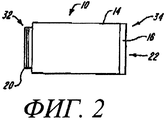
фиг.2 - вид сбоку колпачка из фиг.1,figure 2 is a side view of the cap of figure 1,
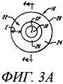
фиг.3А - вид с торца колпачка из фиг.1,figa - end view of the cap of figure 1,
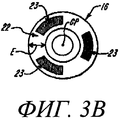
Фиг.3В - вид с торца колпачка из фиг.1, в котором предохраняющий от проскальзывания материал прикреплен к контактному кольцу,Fig. 3B is an end view of the cap of Fig. 1, in which the slip protection material is attached to the slip ring,
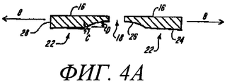
фиг.4А - вид сбоку в поперечном сечении вдоль линии 4-4 на фиг.3, иллюстрирующий контактное кольцо из фиг.3,figa is a side view in cross section along the line 4-4 in figure 3, illustrating the slip ring of figure 3,
фиг.4В - графическое представление профиля давления, создаваемого колпачком из фиг.2,figv is a graphical representation of the pressure profile generated by the cap of figure 2,
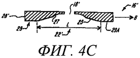
фиг.4С - поперечное сечение альтернативного варианта осуществления контактного кольца ланцетного устройства согласно настоящему изобретению,figs - cross section of an alternative embodiment of the contact ring of the lanceolate device according to the present invention,
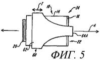
фиг.5 - вид сбоку альтернативного варианта осуществления колпачка для ланцетного устройства согласно настоящему изобретению, иллюстрирующий втулку, расположенную вокруг колпачка в соответствии с настоящим изобретением,5 is a side view of an alternative embodiment of a cap for a lanceolate device according to the present invention, illustrating a sleeve located around the cap in accordance with the present invention,
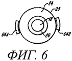
фиг.6 - вид с торца колпачка из фиг.5,6 is an end view of the cap of figure 5,
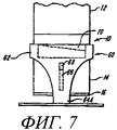
фиг.7 - вид сбоку колпачка из фиг.5, иллюстрирующий колпачок, смещенный от кожи, в соответствии с настоящим изобретением,7 is a side view of the cap of figure 5, illustrating the cap, offset from the skin, in accordance with the present invention,
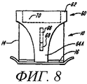
фиг.8 - вид сбоку колпачка из фиг.5, иллюстрирующий колпачок в соприкосновении с кожей, в соответствии с настоящим изобретением,Fig.8 is a side view of the cap of Fig.5, illustrating the cap in contact with the skin, in accordance with the present invention,
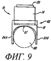
фиг.9 - вид спереди колпачка из фиг.5,Fig.9 is a front view of the cap of Fig.5,
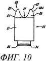
фиг.10 - вид спереди еще одного варианта осуществления колпачка для ланцетного устройства, пригодного для прокалывания кончика пальца, в соответствии с настоящим изобретением,10 is a front view of yet another embodiment of a cap for a lanceolate device suitable for piercing a fingertip, in accordance with the present invention,
фиг.11 - вид с торца колпачка из фиг.10,11 is an end view of the cap of figure 10,
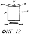
Фиг.12 - вид спереди еще одного варианта осуществления колпачка для ланцетного устройства, предназначенного для прокалывания вентральной стороны кончика пальца, в соответствии с настоящим изобретением,12 is a front view of yet another embodiment of a cap for a lanceolate device for piercing the ventral side of a fingertip, in accordance with the present invention,
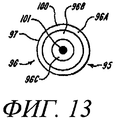
фиг.13 - вид с торца колпачка из фиг.12,Fig.13 is an end view of the cap of Fig.12,
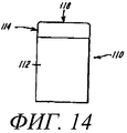
фиг.14 - вид сбоку альтернативного варианта осуществления колпачка согласно настоящему изобретению, образованного из гибкого материала и находящегося в исходном положении,Fig. 14 is a side view of an alternative embodiment of a cap according to the present invention formed of a flexible material and in its initial position,
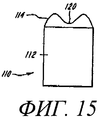
фиг.15 - вид сбоку колпачка из фиг.14 при соприкосновении контактного кольца с местом прокола,Fig - side view of the cap of Fig.14 in contact with the contact ring with the puncture site,
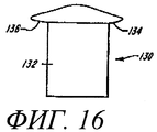
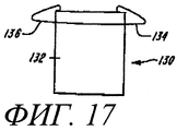
фиг.16 - вид сбоку альтернативного варианта осуществления колпачка согласно настоящему изобретению, образованного из деформируемого гибкого материала и находящегося в исходном положении,Fig is a side view of an alternative embodiment of a cap according to the present invention, formed from a deformable flexible material and located in its original position,
фиг.17 - вид сбоку колпачка из фиг.16 при соприкосновении контактного кольца с местом прокола.Fig.17 is a side view of the cap of Fig.16 in contact with the contact ring with the puncture site.
Описание вариантов осуществленияDescription of Embodiments
Настоящее изобретение относится к колпачку, предназначенному для использования совместно с ланцетным устройством для прокалывания дермальной ткани для получения пробы жидкости, например крови, интерстициальной жидкости или той и другой. Ниже выражение «кровь» использовано для простоты, хотя предполагается, что оно охватывает выражение «интерстициальная жидкость» или ту и другую. Колпачок согласно настоящему изобретению предназначен для содействия получению крови после того, как дермальная ткань проколота, путем повышения давления на дермальную ткань, окружающую место прокола. Это повышение давления приводит к увеличению потока крови из места прокола, в результате чего уменьшается время, необходимое для получения достаточного количества крови, и исключается необходимость помещения ланцетного устройства на поверхность и использования другой свободной руки для выдавливания отбираемой крови.The present invention relates to a cap intended to be used in conjunction with a lanceolate device for piercing dermal tissue to obtain a sample of a fluid, such as blood, interstitial fluid, or both. The expression “blood” is used below for simplicity, although it is intended to encompass the expression “interstitial fluid” or both. The cap according to the present invention is intended to facilitate the production of blood after the dermal tissue is punctured by increasing pressure on the dermal tissue surrounding the puncture site. This increase in pressure leads to an increase in blood flow from the puncture site, which reduces the time required to obtain a sufficient amount of blood, and eliminates the need to place a lancet device on the surface and use another free hand to extrude the blood sampled.
Кроме того, колпачок согласно настоящему изобретению особенно пригоден для сбора проб крови из мест прокола не на кончике пальца пациента, который является традиционным местом для сбора проб крови. Использование таких альтернативных мест может быть менее болезненным для пациента и, кроме того, позволяет пациенту «дать отдых» кончику своего пальца. Подходящие альтернативные места включают, но без ограничения ими, предплечья, верхние конечности, бедра, ладони и живот пациента. Сбор проб крови из альтернативных мест может быть проблематичным, поскольку приложение вручную достаточного давления на дермальную ткань, прилегающую к месту прокола, для сбора пробы крови может оказаться затруднительным и обычно приводит к низкой производительности. Колпачок согласно настоящему изобретению обеспечивает пользователю возможность повышать степень давления возле места прокола, вследствие чего из альтернативного места отбора можно получать достаточное количество крови.In addition, the cap according to the present invention is particularly suitable for collecting blood samples from puncture sites not at the fingertip of the patient, which is a traditional place for collecting blood samples. The use of such alternative places can be less painful for the patient and, in addition, allows the patient to “give rest” to the tip of his finger. Suitable alternative locations include, but are not limited to, the forearm, upper limbs, hips, palms, and abdomen of the patient. Collecting blood samples from alternative locations can be problematic, since manually applying sufficient pressure to the dermal tissue adjacent to the puncture site to collect a blood sample can be difficult and usually leads to poor performance. The cap according to the present invention allows the user to increase the degree of pressure near the puncture site, whereby a sufficient amount of blood can be obtained from the alternative sampling site.
Колпачок 10 в соответствии с одним предпочтительным вариантом осуществления настоящего изобретения показан на фиг.1-4. Колпачок 10 выполнен с возможностью присоединения к дистальному концу кожуха 12 обычного ланцетного устройства. В обычном ланцетном устройстве ланцет 30 расположен внутри кожуха 12 ланцетного устройства и выполнен подвижным относительно кожуха 12 вдоль первой оси, обозначенной линией А на фиг.1. Для прокалывания дермальной ткани ланцет 30 ланцетного устройства можно привести в движение вдоль первой оси. Затем можно получить пробу крови путем сбора из места прокола. Такие обычные ланцетные устройства можно приобрести от Lifescan, Inc. из Милпитаса, Калифорния, Palco Laboratories из Санта-Круза, Калифорния, Therasense из Аламеды, Калифорния, и Amira Medical из Скотсвейла, Калифорния. Кроме того, ланцетные устройства описаны в патентах США №№5730753 (Morita), 6045567 (Taylor) и 6071250 (Douglas). Каждый из этих вышеупомянутых патентов включен в настоящую заявку посредством ссылки. Специалисту в данной области техники должно быть понятно, что использование колпачка согласно настоящему изобретению не ограничено ланцетными устройствами, описанными в настоящей заявке. Колпачок согласно настоящему изобретению может быть применен совместно с любым ланцетным устройством, в котором использован подвижный ланцет для прокалывания дермальной ткани. Кроме того, настоящее изобретение предполагается использующим любое устройство, пригодное для получения пробы жидкости от пациента с применением различных средств извлечения, включая использование ланцетов, полых и сплошных игл или микроигл, ультразвуковых устройств, термических средств. Устройство может быть простым ланцетным устройством, описанным выше, или может быть устройством, имеющим встроенные дозаторы или измерительные приборы, пригодные для выполнения анализа, например, на глюкозу.A
Как лучше всего показано на фиг.2, колпачок 10 включает в себя корпус 14 колпачка, имеющий проксимальный конец 32 и дистальный конец 34. Контактное кольцо 16 прикреплено к дистальному концу 34 корпуса 14 колпачка. Чтобы обеспечить возможность прохождения части ланцета 30 сквозь контактное кольцо 16 для прокалывания дермальной ткани, в кольце предусмотрено отверстие 18, показанное на фиг.3А и 4.As best shown in FIG. 2,
На фиг.2 показано, что корпус 14 колпачка может включать в себя соединитель 20 для присоединения с возможностью удаления и замены проксимального конца 32 корпуса 14 колпачка к дистальному концу кожуха 12 ланцетного устройства. Предпочтительно, чтобы соединитель 20 был выполнен с резьбой для сопряжения с соответствующими витками резьбы, предусмотренными в кожухе 12 ланцетного устройства. Специалист в данной области техники должен понимать, что альтернативные соединительные устройства могут быть использованы без отступления от объема настоящего изобретения. Например, соединитель 20 может иметь размеры и форму, обеспечивающие посадку с защелкиванием в кожух 12. Кроме того, колпачок 10 может быть постоянно прикреплен к кожуху 12, хотя предпочтительно, чтобы колпачок 10 присоединялся с возможностью удаления и замены к кожуху 12.Figure 2 shows that the
Корпус 14 колпачка может быть изготовлен из прозрачного, просвечивающего или матового материала, например из светлого прозрачного пластика, или может включать в себя прозрачный участок, образующий окно внутрь корпуса колпачка, или может быть изготовлен из обычного непрозрачного материала. Если материал является прозрачным, то его прозрачность должна быть достаточной для того, чтобы обеспечивалась возможность наблюдения получаемой крови внутри корпуса 14 колпачка. Как рассмотрено более подробно ниже, прозрачность корпуса 14 колпачка позволяет пользователю видеть количество получаемой крови в случае сбора из места прокола.The
На фиг.3А и 4А показано, что предпочтительно, чтобы контактное кольцо 16 имело многопрофильную поверхность 22 для соприкосновения с дермальной тканью как во время прокалывания, так и во время получения пробы крови. Многопрофильная поверхность 22 ориентирована в основном вокруг второй оси, показанной линией В на фиг.4А, отличной от первой оси А. В предпочтительном варианте осуществления, описанном в настоящей заявке, вторая ось В перпендикулярна первой оси А. Специалист в данной области техники должен понимать, что ориентация этой второй оси не ограничена этой предпочтительной ориентацией и что может использоваться любая ориентация, отличная от оси перемещения ланцета.Figures 3A and 4A show that it is preferable that the
Многопрофильная поверхность 22 предназначена для оказания давления на дермальную ткань для максимизации скорости потока крови от периферии придавленного участка к центру места прокола и для содействия получению пробы крови для сбора. Термин «многопрофильная поверхность», использованный в настоящей заявке, предполагает содержание двух или более поверхностей, ориентированных под различными углами относительно друг друга и относительно общей оси. Многопрофильная поверхность может проходить внутрь от вертикальной стенки или может проходить внутрь от плоской поверхности, проходящей в радиальном направлении внутрь от вертикальной стенки. Специалисты в данной области техники должны понимать, что многопрофильная поверхность может включать в себя любое выбранное число поверхностей. В соответствии с одним практическим осуществлением поверхность может быть неплоской. В одном варианте осуществления, описанном в настоящей заявке, многопрофильная поверхность 22 состоит из внешнего радиального участка 24 и внутреннего радиального участка 26, прилегающего к отверстию 18. Предпочтительно, чтобы внешний радиальный участок 24 был ориентирован под первым углом С относительно второй оси В. Предпочтительно, чтобы внутренний радиальный участок 26 был ориентирован относительно второй оси В под вторым углом D, отличным от первого угла С. Внешний радиальный участок 24 и внутренний радиальный участок 26 могут иметь любую выбранную характеристику или форму поверхности, например могут быть линейными, ступенчатыми или криволинейными. В иллюстративном варианте осуществления внешний радиальный участок 24 в основном линейный от периметра 28 контактного кольца 16 до пересечения с внутренним радиальным участком 26. В качестве варианта внешний радиальный участок 26 может быть выпуклым или вогнутым в случае искривления. Кроме того, внутренний радиальный участок 26 выполнен, как правило, вогнутым 5 случае искривления, но также может быть линейным или выпуклым.The
как показано на фиг.4А, угол С, соответствующий наклону внешнего радиального участка 24, находится в пределах от приблизительно 5° до приблизительно 15°. Кроме того, предпочтительно, чтобы радиальная протяженность внешнего радиального участка 24, в целом показанная линией Е на фиг.3А, составляла от приблизительно 25% до приблизительно 75% полного радиуса контактного кольца 16, измеренного от центральной точки СР контактного кольца 16 до периметра 28 контактного кольца 16. В предпочтительном варианте осуществления предпочтительно, чтобы радиальная протяженность Е внешнего радиального участка 24 составляла приблизительно 50% полного радиуса контактного кольца 16.as shown in FIG. 4A, the angle C corresponding to the inclination of the outer
Контактное кольцо 16 может быть изготовлено из пластика или из других материалов, пригодных для использования в медицинских инструментах. Контактное кольцо 16 может быть непрозрачным и суметь цвет, например белый, который отличается от и контрастирует с цветом дермальной ткани. Контрастирующий цвет дает возможность пользователю лучше представлять количество полученной крови.The
Контактное кольцо 16 может быть отдельной дискретной деталью, прикрепляемой к корпусу 14 колпачка, или может быть выполнено за одно целое с корпусом 14 колпачка.The
На фиг.4В контактное кольцо 16 колпачка 10 имеет форму и размеры, обеспечивающие плотное соприкосновение с кожей пациента. При помещении в соприкосновение с кожей контактное кольцо создает градиент давления, который продолжается внутрь от радиальной внешней поверхности к отверстию 18. В частности, когда кожа проколота ланцетом 30, контактное кольцо 16, расположенное вокруг места прокола, создает градиент давления, который побуждает жидкость протекать к отверстию 18, что показано стрелками 19.In FIG. 4B, the
Профиль 31 давления, создаваемый колпачком 10, имеет максимумы 33 давления, которые совпадают с участком периметра колпачка или с началом многопрофильной поверхности 22. На этом участке давление максимально, поскольку колпачок в большей степени соприкасается с кожей пациента. По мере прохождения поверхностей многоконтурной поверхности внутрь к отверстию 18 и отдаления от кожи суммарное давление снижается. Это создает градиент давления, который продолжается от самого наружного участка колпачка 10 до отверстия 18. Показанный профиль 31 давления спадает до некоторой степени равномерно на протяжении поверхности 24 и более быстро на протяжении поверхности 26. Специалисты в данной области должны понимать, что профиль давления будет изменяться в зависимости от конфигурации контактного кольца.The
В соответствии с альтернативным вариантом осуществления изобретения, показанным на фиг.3В, контактное кольцо 16 может включать в себя элемент, предохраняющий от проскальзывания, выполненный с возможностью предотвращения перемещения контактного кольца 16 и колпачка 10 относительно (или по) поверхности кожи во время получения пробы крови. В соответствии с одним вариантом осуществления элемент, предохраняющий от проскальзывания, выполнен из соответствующего, предохраняющего от проскальзывания материала 23, например из резины или силикона, который прикреплен, присоединен к или придан части многоконтурной поверхности 22 контактного кольца. Предохраняющий от проскальзывания материал 23 обеспечивает достаточное трение между контактным кольцом и кожей для оказания сопротивления перемещению контактного кольца относительно поверхности кожи. Чтобы увеличить трение между контактным кольцом и кожей, в соответствии с альтернативным вариантом осуществления, многоконтурная поверхность может быть образована с выбранными поверхностными элементами, например, с выступами или выемками, или может быть выполнена шероховатой. В качестве варианта для предотвращения перемещения все контактное кольцо может быть изготовлено из предохраняющего от проскальзывания материала.In accordance with an alternative embodiment of the invention shown in FIG. 3B, the
На фиг.4С показан другой вариант осуществления контактного кольца 16 колпачка 10 согласно настоящему изобретению. Подобные или аналогичные детали обозначены теми же самыми ссылочными номерами с добавлением верхнего индекса. Показанное контактное кольцо 16' имеет вытянутую по направлению оси или вертикально наружную стенку или периметр 28', который ограничивает дистальный конец 29. Дистальный конец 29 включает в себя первый плоский передний участок 29А, который выполнен с возможностью прижима к коже пациента во время использования. Плоский передний участок 29А обычно расположен перпендикулярно участку 28' периметра. Многопрофильная поверхность 22' проходит в радиальном направлении внутрь от плоского переднего участка 29А к отверстию 18'. Как показано с помощью обозначения L, многопрофильная поверхность 22' проходит между кольцевым плоским передним участком 29А. Кроме того, многопрофильную поверхность можно выполнить так, что она будет включать в себя плоский передний участок 29А. В этом варианте осуществления многоконтурная поверхность состоит из трех поверхностей. По усмотрению, чтобы предотвратить перемещение контактного кольца относительно поверхности кожи во время получения пробы крови, в контактное кольцо 16' может быть включен элемент, предохраняющий от проскальзывания, содержащий предохраняющий от проскальзывания материал или имеющий шероховатую поверхность.4C shows another embodiment of a
Показанная многопрофильная поверхность 22' включает в себя две или более поверхностей, ориентированных относительно друг друга с образованием различных, отличающихся углов. В частности, многопрофильная поверхность 22' включает в себя пару поверхностей 25 и 27. Внешняя в радиальном направлении поверхность 25 ориентирована под первым углом относительно оси В. Внутренняя в радиальном направлении поверхность 27 ориентирована под вторым углом относительно оси 3, отличным от первого угла. Как описано выше, поверхности 25 и 27 могут иметь любую выбранную форму или любое угловое расположение.The
При использовании колпачок 10 соединяют с кожухом 12 ланцетного устройства и прокалывают дермальную ткань ланцетом 30, проходящим сквозь отверстие 18 в контактном кольце 16. Затем ланцет 30 отводят назад в колпачок 10 или в ланцетное устройство. Прижимают контактное кольцо 16, находящееся в соприкосновении с дермальной тканью, прилегающей к месту прокола, вынуждая кровь вытекать из места прокола и втекать в колпачок 10 через отверстие 18. Дермальная ткань «сдавливается» при соприкосновении с внешним радиальным участком 24 и внутренним радиальным участком 26 многопрофильной поверхности 22. Многопрофильная поверхность 22 облегчает получение крови путем повышения гидростатического давления на дермальную ткань, находящуюся в соприкосновение с периметром 28 контактного кольца 16. Гидростатическое давление на дермальную ткань уменьшается по мере изменения наклона внешней радиальной поверхности 24 и внутренней радиальной поверхности по направлению к отверстию 18. Этот продолжающийся внутрь градиент давления показан на фиг.4В. Путем экспериментального исследования обнаружено, что, используя колпачок 10 согласно настоящему изобретению для отбора не из пальца, а из иных мест, можно легко получать из места прокола от 1,5 до 3 мл крови. Кроме того, поскольку корпус 14 колпачка может быть выполнен прозрачным, а контактное кольцо может быть контрастирующего цвета, например белого, пользователь может легко контролировать объем получаемой крови.In use, the
На фиг.5-9 показан альтернативный вариант осуществления колпачка согласно настоящему изобретению, в котором вокруг корпуса 14 колпачка расположена втулка 60. Втулка 60 выполнена подвижной в основном вдоль первой оси А, то есть вдоль оси перемещения ланцета, и относительно корпуса 14 колпачка. Втулка 60 имеет кольцо 62 и по меньшей мере две ножки 64А и 64В, которые вытянуты от кольца 62 по направлению первой оси А к дистальному концу 34 колпачка 10. Ножки 64А и 643 сужаются от большей ширины вблизи кольца 62 до меньшей ширины вблизи контактного кольца 16.5 to 9 show an alternative embodiment of a cap according to the present invention, in which a
Как показано на фиг.6, ножки 64А и 64В выполнены дугообразными в поперечном сечении и охватывают только часть окружности контактного кольца 16. Предпочтительно, чтобы ножки 64А и 64В были расположены симметрично вокруг периметра контактного кольца 16. Хотя показаны только две ножки, специалисту в данной области техники должно быть понятно, что дополнительные ножки могут быть добавлены без отступления от настоящего изобретения. Кроме того, нет необходимости в том, чтобы ножки были расположены симметрично вокруг контактного кольца 16.As shown in FIG. 6, the
Предпочтительно, чтобы втулка 60 могла скользить вдоль оси, параллельной первой оси А, как показано стрелкой Т на фиг.5. Проходящий в продольном направлении паз 66 может быть образован в одной или в обеих поверхностях корпуса 14 втулки. Выступающий направляющий элемент 68 может быть образован на одной или обеих ножках 64А и 64В. Направляющий элемент 68 имеет размеры и форму, обеспечивающие скольжение внутри паза 66 и исключение поперечного перемещения втулки 60 относительно корпуса 14 колпачка. В качестве варианта паз 66 может быть образован в одной или более ножках 64А и 64В, а направляющий элемент 68 может быть образован на корпусе 14 колпачка.Preferably, the
Для смещения втулки 60 к дистальному концу колпачка 10 может быть предусмотрена пружина 70 или другой смещающий механизм. Специалисту в данной области техники должно быть понятно, что использование втулки 60 не ограничено колпачком 10 согласно настоящему изобретению, а она может использоваться совместно с колпачком любого ланцетного устройства.To
Иногда после прокалывания необходимо вывести колпачок 10 и контактное кольцо 16 из соприкосновения с дермальной тканью, например, для снятия давления с дермальной ткани или для визуального исследования места прокола. Как показано на фиг.7, втулка 60 обеспечивает пользователю возможность сохранять часть ланцетного устройства, ножки 64А и 64В втулки 60, в соприкосновении с кожей, когда колпачок 14 и контактное кольцо 16 выведены из соприкосновения с кожей. Существенно, что ножки 64А и 64В обеспечивают пользователю возможность сохранять отверстие 18 в совмещении с местом прокола после возвращения контактного кольца в соприкосновение с дермальной тканью, что показано на фиг.8. В соответствии с одним вариантом осуществления ножки 64А и 64В втулки дополнительно включают в себя элемент, предохраняющий от проскальзывания, для предотвращения перемещения втулки относительно кожи. Чтобы предотвратить перемещение, предохраняющий от проскальзывания материал, например резина или силикон, может быть прикреплен к контактной поверхности ножек втулки. В качестве варианта элемент, предохраняющий от проскальзывания, имеет шероховатую поверхность в месте соприкосновения ножек втулки с кожей.Sometimes, after piercing, it is necessary to remove the
На фиг.9 показано, что ножки 64А и 64В могут быть разнесены на расстояние, достаточное для размещения пальца 80 пациента между ножками 64А и 64В. Поверхности 67, соединяющие две ножки 64А и 64В, могут быть криволинейными, а для обеспечения дополнительного удобства пальцу 80 пациента предпочтительно, чтобы они были параболическими по форме. Кроме того, ножки 64А и 64В, а также втулка 60 могут быть изготовлены из гибкого упругого материала, например из гибкого пластика. Предпочтительным материалом является сополимер акрилонитрила, бутадиена и стирола. Как показано на фиг.9, палец 8С пациента может быть расположен между ножнами 64А и 64В в тех случаях, когда втулка 60 находится на нижней части колпачка 10. Ножки 64А и 64В давят на палец пациента, сдавливая или сжимая дермальную ткань. После этого палец пациента может быть проколот, а сдавливание пальца пациента ножками 64А и 64В может облегчить получение крови из места прокола.Figure 9 shows that the
Альтернативные варианты осуществления колпачка согласно настоящему изобретению показаны на фиг.10-13, где контактное кольцо 16 обеспечивает возможность прокалывания крутого изгиба (или боковой поверхности) кончика пальца, а также вентральной стороны кончиков пальцев.Alternative embodiments of the cap according to the present invention are shown in FIGS. 10-13, where the
На фиг.10 и 11 показан еще один вариант осуществления колпачка согласно настоящему изобретению. Колпачок 80 включает в себя корпус 31 колпачка, имеющий проксимальный конец 86. Контактное кольцо 85 прикреплено к дистальному концу 83 корпуса 81 колпачка. В контактном кольце 85 предусмотрено отверстие 92 для обеспечения возможности прохождения части ланцета 30 для выполнения прокола кончика пальца. Показанный корпус 81 колпачка может включать в себя соединитель 84 для присоединения с возможностью удаления и замены проксимального конца 86 корпуса 81 колпачка к дистальному концу кожуха 12 ланцетного устройства. Например, соединитель 84 может иметь размеры и форму, обеспечивающие посадку в кожух 12. Колпачок 80 может быть постоянно прикреплен к кожуху 12, хотя предпочтительно, чтобы колпачок 80 присоединялся с возможностью удаления и замены к кожуху 12.10 and 11 show yet another embodiment of a cap according to the present invention. The
Корпус 81 колпачка изготовлен из прозрачного, просвечивающего или матового материала, например из светлого или прозрачного пластика, или включает в себя прозрачный участок, образующий окно внутрь корпуса колпачка. Материал должен быть достаточно прозрачным, чтобы пользователь мог видеть получаемую кровь внутри корпуса 81 колпачка. Прозрачность корпуса 81 колпачка позволяет видеть количество крови, получаемой из прокола в продолжение сбора.The cap body 81 is made of a transparent, translucent, or opaque material, for example light or transparent plastic, or includes a transparent portion forming a window inside the cap body. The material must be transparent enough so that the user can see the blood received inside the cap body 81. The transparency of the cap body 81 allows you to see the amount of blood received from the puncture during collection.
Предпочтительно, чтобы контактное кольцо 85 содержало пару прижимных крылышек 82, которым приданы размеры и форма, обеспечивающие согласование с крутым изгибом кончика пальца, расположенного между ними. Поэтому прижимные крылышки 82 образуют выемку 87 для размещения пальца пациента. Это создает давление точной величины, обеспечивающее получение крови.Preferably, the
На фиг.11 показано, что прижимные крылышки вытянуты как в радиальном направлении, так и наружу, и на расстоянии от контактного кольца для обеспечения соприкосновения с кончиком пальца как при прокалывании, так и при отборе крови при сжатии. Прижимные крылышки 82 и 82 образуют многопрофильную поверхность, которая проходит от внешнего контура корпуса 81 к отверстию 92. Многоконтурная поверхность 88 предназначена для сдавливания кончика пальца для максимизации скорости потока крови из места прокола и облегчения получения крови для сбора пробы. Показанная многопрофильная поверхность 88 содержит две или более неплоских поверхностей, расположенных под различными углами относительно друг друга и относительно общей оси. Например, прижимные крылышки 82, 82, образующие многопрофильную поверхность 88, содержат радиальный внешний участок 88А и криволинейный радиальный внутренний участок 88В, прилегающий к отверстию 92. Место перехода между поверхностями 88А и 88В может быть дугообразным, скругленным или крутым.11 shows that the clamping wings are elongated both radially and outward, and at a distance from the contact ring to ensure contact with the fingertip both when piercing and when taking blood during compression. The
Показанное контактное кольцо 85 может быть изготовлено из пластика или из других материалов, пригодных для использования в медицинских инструментах. Контактное кольцо 85 может быть непрозрачным, имеющим цвет, отличный от цвета кончика пальца. Предпочтительным цветом является белый. Контрастирующий цвет обеспечивает пользователю лучшее наблюдение за количеством получаемой крови. Контактное кольцо 85 может быть отдельным дискретным элементом, прикрепленным к корпусу 81 колпачка, или может быть выполнено за одно целое с корпусом 81 колпачка.The
При использовании колпачок 80 присоединяют к кожуху 12 ланцетного устройства, а пациент помещает кончик пальца в выемку 87, образованную прижимными крылышками 82, 82. Ланцет 30 устройства приводят в действие и он проходит сквозь отверстие 92 в контактном кольце 85, чтобы проколоть кожу. Для получения крови контактное кольцо 85 а положении соприкосновения прижимают к кончику пальца вблизи места прокола. Многопрофильная поверхность 87 содействует получению крови путем создания градиента давления, который продолжается в радиальном направлении внутрь к отверстию 92. В соответствии с альтернативным вариантом осуществления элемент, предохраняющий от проскальзывания, на контактном кольце 85 предотвращает перемещение контактного кольца относительно поверхности кожи, когда контактное кольцо в положении соприкосновения прижато к кончику пальца. Как обсуждалось, элемент, предохраняющий от проскальзывания, может представлять собой подходящий предохраняющий от проскальзывания материал, прикрепленный к многопрофильной поверхности, или многопрофильная поверхность может быть выполнена шероховатой. Чтобы получить сопротивление проскальзыванию, в качестве варианта контактное кольцо 85 может быть изготовлено полностью из подходящего предохраняющего от проскальзывания материала.In use, a
На фиг.12 и 13 показан еще один вариант осуществления колпачка согласно настоящему изобретению. Как показано на фиг.12, колпачок 90 включает в себя контактное кольцо 95, прикрепленное к дистальному концу 97 корпуса 94 колпачка. Отверстие 124, образованное в контактном кольце 95, обеспечивает возможность прохождения ланцета 30 для образования прокола на вентральной стороне кончика пальца.12 and 13 show yet another embodiment of a cap according to the present invention. As shown in FIG. 12,
Корпус 94 колпачка включает в себя соединитель 99 для присоединения с возможностью удаления и замены проксимального конца 98 корпуса 94 колпачка к дистальному концу кожуха 12. Например, соединитель 99 может иметь размеры и форму, обеспечивающие посадку в кожух 12. Кроме того, колпачок 90 может быть постоянно прикреплен к кожуху 12. Предпочтительно, чтобы колпачок 90 присоединялся с возможностью удаления и замены к кожуху 12. Предпочтительно, чтобы корпус 94 колпачка был аналогичен корпусу 81 колпачка из фиг.10. Материалы для колпачка 80 также те же самые, что и для колпачка 90. Материал может быть прозрачным или может включать прозрачный участок для наблюдения получаемой крови внутри колпачка 90.The
Показанное контактное кольцо 95 имеет многопрофильную поверхность 96, которая проходит от периметра корпуса 94 колпачка к центральному отверстию 101. Многопрофильная поверхность 96 может включать в себя две или более поверхностей, расположенных под различными углами относительно друг друга и относительно общей оси. Например, показанная многопрофильная поверхность 96 состоит из наружного радиального участка 96А, среднего участка 96В и внутреннего радиального участка 96С, прилегающего к отверстию 101. Внешний, средний и внутренний радиальные участки колпачка могут иметь любую выбранную характеристику или форму поверхности, то есть могут быть линейными, ступенчатыми или криволинейной. Кроме того, места перехода между каждой поверхностью 96А, 96В и 96С многопрофильной поверхностью могут иметь признаки скругленной, дугообразной или крутой поверхности.The
Показанное контактное кольцо 95 может быть изготовлено из пластика или из другого материала, пригодного для использования в медицинских инструментах. Контактное кольцо 95 может быть непрозрачным, имеющим цвет, который отличен от цвета кончика пальца. Предпочтительным цветом является белый. Контрастирующий цвет обеспечивает пользователю возможность лучшего наглядного представления количества получаемой крови. Как и в колпачке 80, контактное кольцо 95 может быть отдельной, дискретной деталью, прикрепленной к корпусу 94 колпачка, или может быть выполнено за одно целое с корпусом 94 колпачка.The
При использовании колпачок 90 присоединяют к кожуху 12 ланцетного устройства, а кончик пальца помещают на него с образованием плотного соприкосновения с вентральной стороной и прокалывают ланцетом 30, проходящим сквозь отверстие 101 в контактном кольце 96. Ланцет 30 отводят в колпачок 90 или в ланцетное устройство. Кончик пальца обжимают в положении соприкосновения с внешним радиальным участком 96А, средним радиальным участком 96В и внутренним радиальным участком 96С многопрофильной поверхности 96. Многопрофильная поверхность 96 облегчает получение крови путем создания градиента давления, который продолжается в радиальном направлении внутрь к отверстию 101 от периметра 100 контактного кольца 95 или корпуса 94 колпачка. В соответствии с одним вариантом осуществления элемент, предохраняющий от проскальзывания, наводящийся на контактного кольце 95, предотвращает перемещение контактного кольца относительно поверхности кожи, когда контактное кольцо прижато в положении соприкосновения к пальцу. Как обсуждалось, элемент, предохраняющей от проскальзывания, может представлять собой подходящий предохраняющий от проскальзывания материал, например резину или силикон, прикрепленный к многопрофильной поверхности. В качестве варианта по меньшей мере участок многопрофильной поверхности представляет собой шероховатую поверхность для создания трения между контактным кольцом и кожей.When using the
Альтернативный вариант осуществления колпачка согласно настоящему изобретению показан на фиг.14-17, где контактная область, выполненная из гибкого материала, предназначена для прокалывания разнообразных поверхностей пациента.An alternative embodiment of the cap according to the present invention is shown in FIGS. 14-17, where a contact area made of flexible material is intended to pierce a variety of patient surfaces.
На фиг.14 и 15 показан еще один вариант осуществления колпачка, в соответствии с настоящим изобретением предназначенный для использования на многочисленных различных местах прокола. Показанный колпачок 110 включает в себя корпус 112 колпачка, который заканчивается на контактном кольце 114, установленном на дистальном конце. Дистальный конец 115 колпачка 110 может быть соединен с кожухом 12 посредством любой подходящей конструкции. В соответствии с предпочтительным вариантом осуществления колпачок постоянно прикреплен к кожуху и, следовательно, не может перемешаться относительно него в осевом направлении. По желанию, контактное кольцо 114 колпачка 110 может включать в себя многопрофильную поверхность 118, имеющую большое количество поверхностей, ориентированных под углами относительно друг друга. Кроме того, в нем может быть образовано центральное отверстие. В соответствии с альтернативным вариантом осуществления контактное кольцо может быть цельной конструкцией с заданными поверхностными элементами, образованными на нем.On Fig and 15 shows another embodiment of a cap in accordance with the present invention intended for use at many different places of puncture. The
Предпочтительно, чтобы рассматриваемое контактное кольцо было изготовлено из деформируемого упругого гибкого материала, который может принимать форму участка тела пациента при соприкосновении с ним. Предпочтительно, чтобы контактное кольцо было изготовлено из резины, полиуретана, латекса или из другого гибкого материала. Корпус 112 колпачка также может быть изготовлен из любого подходящего прозрачного, просвечивающего или матового материала, например из светлого или прозрачного пластика, или он может включать в себя прозрачный участок, образующий окно внутрь корпуса колпачка, для обеспечения пользователю возможности наблюдения получаемой крови. В качестве варианта колпачок может быть изготовлен из непрозрачного материала.Preferably, the contact ring in question is made of a deformable elastic flexible material that can take the form of a portion of the patient’s body in contact with it. Preferably, the contact ring is made of rubber, polyurethane, latex or other flexible material. The
Контактное кольцо 114 может находиться в исходном положении (фиг.14), когда оно не соприкасается с местом прокола, и, следовательно, кольцу не придается форма места прокола. При помещении в соприкосновение с местом прокола, например с вентральной стороной пальца или с любым другим подходящим участком пальца, контактное кольцо принимает форму места прокола (фиг.15). В соответствии с одним вариантом осуществления элемент, предохраняющий от проскальзывания, на контактном кольце 114 предотвращает перемещение контактного кольца относительно поверхности кожи, когда контактное кольцо прижато в положении соприкосновения к кончику пальца. Как рассматривалось, элемент, предохраняющий от проскальзывания, может представлять собой подходящий предохраняющий от проскальзывания материал, например резину или силикон, прикрепленный к многопрофильной поверхности. В качестве варианта по меньшей мере участок многопрофильной поверхности имеет шероховатую поверхность соприкосновения для создания трения между контактным кольцом и кожей.The
В соответствии с альтернативным вариантом осуществления, показанным на фиг.16 и 17, колпачок 130 включает в себя корпус 132 колпачка, на котором расположено деформируемое контактное кольцо 134. Показанное контактное кольцо 134 имеет краевые участки 136, которые вытянуты за пределы или наружу от периметра корпуса 132 колпачка. По желанию, контактное кольцо может включать в себя многопрофильную поверхность, имеющую большое количество поверхностей, ориентированных под углами относительно друг друга. В нем также может быть образовано центральное отверстие. В соответствии с альтернативным вариантом осуществления контактное кольцо может быть цельной конструкцией с заданными поверхностными элементами, образованными на нем.According to an alternative embodiment shown in FIGS. 16 and 17,
Предпочтительно, чтобы контактное кольцо было изготовлено из резины, полиуретана, латекса или из другого гибкого материала. Контактное кольцо 134 может находиться в исходном положении (фиг.16), когда оно не соприкасается с местом прокола и, следовательно, кольцу не придается форма места прокола. При помещении в соприкосновение с местом прокола, например с вентральной стороной кончика пальца или с другим подходящим участком пальца, контактное кольцо 134 принимает форму места прокола (фиг.17). Кроме того, при нахождении в этом положении выступающие участки деформируемого контактного кольца могут «поворачиваться» и вытягиваться вдоль наружной поверхности корпуса 132 колпачка, вследствие чего его можно использовать на более плоских участках кожи, например на предплечье.Preferably, the contact ring is made of rubber, polyurethane, latex or other flexible material. The
Корпус 132 колпачка может включать в себя соединитель для присоединения с возможностью удаления и замены проксимального конца корпуса 132 колпачка к дистальному концу кожуха 12. В соответствии с одним практическим осуществлением колпачок 13С может быть постоянно прикреплен к кожуху 12. Предпочтительно, чтобы колпачок 130 был присоединен с возможностью удаления и замены к кожуху 12.The
Поскольку в вышеуказанных конструкциях некоторые изменения могут быть сделаны без отступления от объема изобретения, предполагается, что весь материал, содержащийся в приведенном выше описании или показанный на сопровождающих чертежах, должен интерпретироваться как иллюстративный и не являющийся ограничивающим.As some changes may be made in the above constructions without departing from the scope of the invention, it is assumed that all material contained in the above description or shown in the accompanying drawings should be interpreted as illustrative and not limiting.
Кроме того, должно быть понятно, что приведенная ниже формула изобретения охватывает все общие и конкретные особенности изобретения, а все формулировки объема изобретения, сделанные на основании изложения, подпадают под них.In addition, it should be clear that the following claims cover all general and specific features of the invention, and all wording of the scope of the invention made on the basis of the presentation fall under them.
Claims (30)
Applications Claiming Priority (4)
| Application Number | Priority Date | Filing Date | Title |
|---|---|---|---|
| US21080800P | 2000-06-09 | 2000-06-09 | |
| US60/210,808 | 2000-06-09 | ||
| US26151301P | 2001-01-12 | 2001-01-12 | |
| US60/261,513 | 2001-01-12 |
Publications (2)
| Publication Number | Publication Date |
|---|---|
| RU2002132895A RU2002132895A (en) | 2004-03-27 |
| RU2269954C2 true RU2269954C2 (en) | 2006-02-20 |
Family
ID=26905524
Family Applications (1)
| Application Number | Title | Priority Date | Filing Date |
|---|---|---|---|
| RU2002132895/14A RU2269954C2 (en) | 2000-06-09 | 2001-06-08 | Cap for lancet device for punching dermal tissue (versions), cap for lancet device for punching tip of finger, cap for lancet device for punching curvilinear dermal tissue and lancet device for punching dermal tissue |
Country Status (17)
| Country | Link |
|---|---|
| US (3) | US6706049B2 (en) |
| EP (2) | EP1787583B1 (en) |
| JP (1) | JP4772263B2 (en) |
| KR (1) | KR20030045678A (en) |
| CN (1) | CN100515336C (en) |
| AT (1) | ATE543437T1 (en) |
| AU (2) | AU2001266766B2 (en) |
| CA (1) | CA2412401C (en) |
| CZ (1) | CZ20024006A3 (en) |
| ES (1) | ES2378699T3 (en) |
| IL (2) | IL153295A0 (en) |
| MX (1) | MXPA02012175A (en) |
| NO (1) | NO20025880L (en) |
| PL (2) | PL195673B1 (en) |
| RU (1) | RU2269954C2 (en) |
| TW (1) | TWI305492B (en) |
| WO (1) | WO2001095806A2 (en) |
Cited By (1)
| Publication number | Priority date | Publication date | Assignee | Title |
|---|---|---|---|---|
| RU2466754C1 (en) * | 2008-09-29 | 2012-11-20 | Вифор (Интернациональ) Аг | Assembled cap and method for making it |
Families Citing this family (143)
| Publication number | Priority date | Publication date | Assignee | Title |
|---|---|---|---|---|
| US6706000B2 (en) * | 1997-11-21 | 2004-03-16 | Amira Medical | Methods and apparatus for expressing body fluid from an incision |
| US6036924A (en) * | 1997-12-04 | 2000-03-14 | Hewlett-Packard Company | Cassette of lancet cartridges for sampling blood |
| US6391005B1 (en) | 1998-03-30 | 2002-05-21 | Agilent Technologies, Inc. | Apparatus and method for penetration with shaft having a sensor for sensing penetration depth |
| ES2378699T3 (en) * | 2000-06-09 | 2012-04-17 | Diabetes Diagnostics, Inc. | Hood for a puncture device |
| US8641644B2 (en) | 2000-11-21 | 2014-02-04 | Sanofi-Aventis Deutschland Gmbh | Blood testing apparatus having a rotatable cartridge with multiple lancing elements and testing means |
| DE10057832C1 (en) * | 2000-11-21 | 2002-02-21 | Hartmann Paul Ag | Blood analysis device has syringe mounted in casing, annular mounting carrying needles mounted behind test strip and being swiveled so that needle can be pushed through strip and aperture in casing to take blood sample |
| AU2002247008B2 (en) | 2001-01-22 | 2006-02-09 | F. Hoffmann-La Roche Ag | Lancet device having capillary action |
| CA2450114A1 (en) * | 2001-06-08 | 2002-12-19 | F. Hoffmann-La Roche Ag | Sampling devices and methods utilizing a horizontal capillary test strip |
| US20020188223A1 (en) * | 2001-06-08 | 2002-12-12 | Edward Perez | Devices and methods for the expression of bodily fluids from an incision |
| US7025774B2 (en) | 2001-06-12 | 2006-04-11 | Pelikan Technologies, Inc. | Tissue penetration device |
| DE60234598D1 (en) | 2001-06-12 | 2010-01-14 | Pelikan Technologies Inc | SELF-OPTIMIZING LANZET DEVICE WITH ADAPTANT FOR TEMPORAL FLUCTUATIONS OF SKIN PROPERTIES |
| EP1404235A4 (en) | 2001-06-12 | 2008-08-20 | Pelikan Technologies Inc | Method and apparatus for lancet launching device integrated onto a blood-sampling cartridge |
| WO2002100252A2 (en) * | 2001-06-12 | 2002-12-19 | Pelikan Technologies, Inc. | Blood sampling apparatus and method |
| US7981056B2 (en) | 2002-04-19 | 2011-07-19 | Pelikan Technologies, Inc. | Methods and apparatus for lancet actuation |
| ATE497731T1 (en) * | 2001-06-12 | 2011-02-15 | Pelikan Technologies Inc | DEVICE FOR INCREASING THE SUCCESS RATE OF BLOOD YIELD OBTAINED BY A FINGER PICK |
| US9795747B2 (en) | 2010-06-02 | 2017-10-24 | Sanofi-Aventis Deutschland Gmbh | Methods and apparatus for lancet actuation |
| US8337419B2 (en) | 2002-04-19 | 2012-12-25 | Sanofi-Aventis Deutschland Gmbh | Tissue penetration device |
| US9427532B2 (en) | 2001-06-12 | 2016-08-30 | Sanofi-Aventis Deutschland Gmbh | Tissue penetration device |
| WO2002100460A2 (en) | 2001-06-12 | 2002-12-19 | Pelikan Technologies, Inc. | Electric lancet actuator |
| US9226699B2 (en) | 2002-04-19 | 2016-01-05 | Sanofi-Aventis Deutschland Gmbh | Body fluid sampling module with a continuous compression tissue interface surface |
| US20030040683A1 (en) * | 2001-07-06 | 2003-02-27 | Peter Rule | Site selection for determining analyte concentration in living tissue |
| US6966880B2 (en) * | 2001-10-16 | 2005-11-22 | Agilent Technologies, Inc. | Universal diagnostic platform |
| US20040098010A1 (en) * | 2001-10-22 | 2004-05-20 | Glenn Davison | Confuser crown skin pricker |
| US7004928B2 (en) | 2002-02-08 | 2006-02-28 | Rosedale Medical, Inc. | Autonomous, ambulatory analyte monitor or drug delivery device |
| US7141058B2 (en) * | 2002-04-19 | 2006-11-28 | Pelikan Technologies, Inc. | Method and apparatus for a body fluid sampling device using illumination |
| US9248267B2 (en) | 2002-04-19 | 2016-02-02 | Sanofi-Aventis Deustchland Gmbh | Tissue penetration device |
| US7491178B2 (en) * | 2002-04-19 | 2009-02-17 | Pelikan Technologies, Inc. | Method and apparatus for penetrating tissue |
| US7708701B2 (en) | 2002-04-19 | 2010-05-04 | Pelikan Technologies, Inc. | Method and apparatus for a multi-use body fluid sampling device |
| US8579831B2 (en) | 2002-04-19 | 2013-11-12 | Sanofi-Aventis Deutschland Gmbh | Method and apparatus for penetrating tissue |
| US7717863B2 (en) | 2002-04-19 | 2010-05-18 | Pelikan Technologies, Inc. | Method and apparatus for penetrating tissue |
| US8784335B2 (en) | 2002-04-19 | 2014-07-22 | Sanofi-Aventis Deutschland Gmbh | Body fluid sampling device with a capacitive sensor |
| US9314194B2 (en) | 2002-04-19 | 2016-04-19 | Sanofi-Aventis Deutschland Gmbh | Tissue penetration device |
| US8702624B2 (en) | 2006-09-29 | 2014-04-22 | Sanofi-Aventis Deutschland Gmbh | Analyte measurement device with a single shot actuator |
| US7175642B2 (en) | 2002-04-19 | 2007-02-13 | Pelikan Technologies, Inc. | Methods and apparatus for lancet actuation |
| US7563232B2 (en) * | 2002-04-19 | 2009-07-21 | Pelikan Technologies, Inc. | Method and apparatus for penetrating tissue |
| US8360992B2 (en) | 2002-04-19 | 2013-01-29 | Sanofi-Aventis Deutschland Gmbh | Method and apparatus for penetrating tissue |
| US7909778B2 (en) | 2002-04-19 | 2011-03-22 | Pelikan Technologies, Inc. | Method and apparatus for penetrating tissue |
| US7976476B2 (en) * | 2002-04-19 | 2011-07-12 | Pelikan Technologies, Inc. | Device and method for variable speed lancet |
| US7371247B2 (en) * | 2002-04-19 | 2008-05-13 | Pelikan Technologies, Inc | Method and apparatus for penetrating tissue |
| US7291117B2 (en) | 2002-04-19 | 2007-11-06 | Pelikan Technologies, Inc. | Method and apparatus for penetrating tissue |
| US7674232B2 (en) * | 2002-04-19 | 2010-03-09 | Pelikan Technologies, Inc. | Method and apparatus for penetrating tissue |
| US7297122B2 (en) | 2002-04-19 | 2007-11-20 | Pelikan Technologies, Inc. | Method and apparatus for penetrating tissue |
| US7547287B2 (en) | 2002-04-19 | 2009-06-16 | Pelikan Technologies, Inc. | Method and apparatus for penetrating tissue |
| US7232451B2 (en) | 2002-04-19 | 2007-06-19 | Pelikan Technologies, Inc. | Method and apparatus for penetrating tissue |
| US7901362B2 (en) | 2002-04-19 | 2011-03-08 | Pelikan Technologies, Inc. | Method and apparatus for penetrating tissue |
| US9795334B2 (en) | 2002-04-19 | 2017-10-24 | Sanofi-Aventis Deutschland Gmbh | Method and apparatus for penetrating tissue |
| US7892185B2 (en) * | 2002-04-19 | 2011-02-22 | Pelikan Technologies, Inc. | Method and apparatus for body fluid sampling and analyte sensing |
| US7229458B2 (en) | 2002-04-19 | 2007-06-12 | Pelikan Technologies, Inc. | Method and apparatus for penetrating tissue |
| US7648468B2 (en) | 2002-04-19 | 2010-01-19 | Pelikon Technologies, Inc. | Method and apparatus for penetrating tissue |
| US7892183B2 (en) | 2002-04-19 | 2011-02-22 | Pelikan Technologies, Inc. | Method and apparatus for body fluid sampling and analyte sensing |
| US7331931B2 (en) | 2002-04-19 | 2008-02-19 | Pelikan Technologies, Inc. | Method and apparatus for penetrating tissue |
| US8267870B2 (en) | 2002-04-19 | 2012-09-18 | Sanofi-Aventis Deutschland Gmbh | Method and apparatus for body fluid sampling with hybrid actuation |
| US7481776B2 (en) * | 2002-04-19 | 2009-01-27 | Pelikan Technologies, Inc. | Method and apparatus for penetrating tissue |
| US8221334B2 (en) | 2002-04-19 | 2012-07-17 | Sanofi-Aventis Deutschland Gmbh | Method and apparatus for penetrating tissue |
| US20120296233A9 (en) * | 2002-09-05 | 2012-11-22 | Freeman Dominique M | Methods and apparatus for an analyte detecting device |
| AU2002368333A1 (en) * | 2002-11-13 | 2004-06-03 | Karim-Frederic Marti | Device transforming the pain of a syringe needle into a tolerable feeling |
| US20060184189A1 (en) * | 2002-11-15 | 2006-08-17 | Lorin Olson | Cap for a dermal tissue lancing device |
| CN100415166C (en) * | 2002-11-15 | 2008-09-03 | 生命扫描有限公司 | Cap for a dermal tissue lancing device |
| US8574895B2 (en) | 2002-12-30 | 2013-11-05 | Sanofi-Aventis Deutschland Gmbh | Method and apparatus using optical techniques to measure analyte levels |
| US20060195128A1 (en) * | 2002-12-31 | 2006-08-31 | Don Alden | Method and apparatus for loading penetrating members |
| EP1584291A4 (en) * | 2003-01-17 | 2009-04-29 | Panasonic Corp | Apparatus for measuring biological component |
| US20040162573A1 (en) * | 2003-02-19 | 2004-08-19 | Kheiri Mohammad A. | Endcap for lancing device and method of use |
| EP1603458A1 (en) * | 2003-03-06 | 2005-12-14 | Lifescan, Inc. | System and method for piercing dermal tissue |
| US7052652B2 (en) | 2003-03-24 | 2006-05-30 | Rosedale Medical, Inc. | Analyte concentration detection devices and methods |
| DE602004028463D1 (en) | 2003-05-30 | 2010-09-16 | Pelikan Technologies Inc | METHOD AND DEVICE FOR INJECTING LIQUID |
| ES2490740T3 (en) | 2003-06-06 | 2014-09-04 | Sanofi-Aventis Deutschland Gmbh | Apparatus for blood fluid sampling and analyte detection |
| WO2006001797A1 (en) | 2004-06-14 | 2006-01-05 | Pelikan Technologies, Inc. | Low pain penetrating |
| US8058077B2 (en) | 2003-06-20 | 2011-11-15 | Roche Diagnostics Operations, Inc. | Method for coding information on a biosensor test strip |
| US8148164B2 (en) | 2003-06-20 | 2012-04-03 | Roche Diagnostics Operations, Inc. | System and method for determining the concentration of an analyte in a sample fluid |
| WO2005023088A2 (en) * | 2003-09-03 | 2005-03-17 | Facet Technologies, Llc | Endcap for a fluid sampling device |
| WO2005034778A1 (en) * | 2003-09-18 | 2005-04-21 | Facet Technologies, Llc | Lancing device end cap with flexing contact elements |
| EP1670372A4 (en) * | 2003-09-18 | 2010-03-24 | Facet Technologies Llc | Lancing device end cap with rocking-actuated surface features |
| US20090105612A1 (en) * | 2003-09-18 | 2009-04-23 | Facet Technologies, Llc | Lancing device end cap with pressure-actuated surface features |
| WO2005033659A2 (en) | 2003-09-29 | 2005-04-14 | Pelikan Technologies, Inc. | Method and apparatus for an improved sample capture device |
| EP1680014A4 (en) | 2003-10-14 | 2009-01-21 | Pelikan Technologies Inc | Method and apparatus for a variable user interface |
| US7299082B2 (en) * | 2003-10-31 | 2007-11-20 | Abbott Diabetes Care, Inc. | Method of calibrating an analyte-measurement device, and associated methods, devices and systems |
| US20050096686A1 (en) * | 2003-10-31 | 2005-05-05 | Allen John J. | Lancing device with trigger mechanism for penetration depth control |
| EP1706016A4 (en) * | 2003-12-31 | 2017-07-05 | Sanofi-Aventis Deutschland GmbH | Improved penetrating member control using auto-pre-tent |
| EP1706026B1 (en) | 2003-12-31 | 2017-03-01 | Sanofi-Aventis Deutschland GmbH | Method and apparatus for improving fluidic flow and sample capture |
| US7822454B1 (en) | 2005-01-03 | 2010-10-26 | Pelikan Technologies, Inc. | Fluid sampling device with improved analyte detecting member configuration |
| US20050159768A1 (en) * | 2004-01-15 | 2005-07-21 | Home Diagnostics, Inc. | Lancing device |
| DE102004002874A1 (en) * | 2004-01-20 | 2005-08-11 | Roche Diagnostics Gmbh | Analyzer for analysis of blood samples |
| US7670352B1 (en) | 2004-03-24 | 2010-03-02 | Caribbean Medical Brokers, Inc. | Adjustable tip with integrated detent for blood lancet system |
| US20050215923A1 (en) * | 2004-03-26 | 2005-09-29 | Wiegel Christopher D | Fingertip conforming fluid expression cap |
| CN1937958A (en) * | 2004-04-01 | 2007-03-28 | 拜尔健康护理有限责任公司 | Endcap for a vacuum lancing fixture |
| US20050234489A1 (en) * | 2004-04-16 | 2005-10-20 | John Allen | Method for lancing a dermal tissue target site |
| US20050234486A1 (en) * | 2004-04-16 | 2005-10-20 | Allen John J | Apparatus for extracting bodily fluid |
| US20050234491A1 (en) * | 2004-04-16 | 2005-10-20 | Allen John J | Method for lancing a dermal tissue target site employing a dermal tissue lancing device with a tiltable cap |
| GB0409354D0 (en) * | 2004-04-27 | 2004-06-02 | Owen Mumford Ltd | Removal of needles |
| US9101302B2 (en) * | 2004-05-03 | 2015-08-11 | Abbott Diabetes Care Inc. | Analyte test device |
| WO2006011062A2 (en) | 2004-05-20 | 2006-02-02 | Albatros Technologies Gmbh & Co. Kg | Printable hydrogel for biosensors |
| EP1765152B1 (en) * | 2004-06-03 | 2017-01-04 | Sanofi-Aventis Deutschland GmbH | Apparatus for an integrated sample capture and analysis disposable |
| WO2005120365A1 (en) | 2004-06-03 | 2005-12-22 | Pelikan Technologies, Inc. | Method and apparatus for a fluid sampling device |
| US9775553B2 (en) | 2004-06-03 | 2017-10-03 | Sanofi-Aventis Deutschland Gmbh | Method and apparatus for a fluid sampling device |
| WO2005120197A2 (en) * | 2004-06-03 | 2005-12-22 | Pelikan Technologies, Inc. | Tissue interface on a fluid sampling device |
| US7384402B2 (en) | 2004-06-10 | 2008-06-10 | Roche Diagnostics Operations, Inc. | Expression pad |
| US7569126B2 (en) | 2004-06-18 | 2009-08-04 | Roche Diagnostics Operations, Inc. | System and method for quality assurance of a biosensor test strip |
| US7766845B2 (en) * | 2004-06-21 | 2010-08-03 | Roche Diagnostics Operations, Inc. | Disposable lancet and lancing cap combination for increased hygiene |
| US7512432B2 (en) | 2004-07-27 | 2009-03-31 | Abbott Laboratories | Sensor array |
| US20080195131A1 (en) * | 2004-07-28 | 2008-08-14 | Facet Technologies, Llc | Lancing Device End Cap With Rocking-Actuated Surface Features |
| PL1632179T3 (en) * | 2004-09-02 | 2008-07-31 | Nipro Corp | Lancet with needle protector |
| US8652831B2 (en) | 2004-12-30 | 2014-02-18 | Sanofi-Aventis Deutschland Gmbh | Method and apparatus for analyte measurement test time |
| US20060281187A1 (en) | 2005-06-13 | 2006-12-14 | Rosedale Medical, Inc. | Analyte detection devices and methods with hematocrit/volume correction and feedback control |
| EP1928304B1 (en) | 2005-09-30 | 2012-10-24 | Intuity Medical, Inc. | Catalysts for body fluid sample extraction |
| US8801631B2 (en) | 2005-09-30 | 2014-08-12 | Intuity Medical, Inc. | Devices and methods for facilitating fluid transport |
| US20070093863A1 (en) * | 2005-10-20 | 2007-04-26 | Pugh Jerry T | Cap for a dermal tissue lancing device |
| US20070093864A1 (en) * | 2005-10-20 | 2007-04-26 | Pugh Jerry T | Method for lancing a dermal tissue target site |
| CN101296656A (en) * | 2005-11-29 | 2008-10-29 | Ttm株式会社 | Body fluid sampler and method therefor |
| GB0524604D0 (en) | 2005-12-02 | 2006-01-11 | Owen Mumford Ltd | Injection method and apparatus |
| GB2434103B (en) * | 2006-01-12 | 2009-11-25 | Owen Mumford Ltd | Lancet firing device |
| WO2007089930A2 (en) * | 2006-01-31 | 2007-08-09 | Facet Technologies, Llc | Lancet with cap-removal guidance |
| US7885698B2 (en) | 2006-02-28 | 2011-02-08 | Abbott Diabetes Care Inc. | Method and system for providing continuous calibration of implantable analyte sensors |
| US20070255178A1 (en) * | 2006-04-27 | 2007-11-01 | Lifescan Scotland, Ltd. | Method for lancing a target site in low ambient light conditions |
| CN101437451B (en) * | 2006-05-10 | 2011-01-05 | 松下电器产业株式会社 | Piercing instrument and piercing needle cartridge |
| US7909842B2 (en) * | 2006-06-15 | 2011-03-22 | Abbott Diabetes Care Inc. | Lancing devices having depth adjustment assembly |
| US20080065130A1 (en) * | 2006-08-22 | 2008-03-13 | Paul Patel | Elastomeric toroidal ring for blood expression |
| JP5764324B2 (en) | 2007-04-30 | 2015-08-19 | エフ ホフマン−ラ ロッシュ アクチェン ゲゼルシャフト | Instruments and systems for the generation and analysis of body fluid samples |
| US20090099437A1 (en) * | 2007-10-11 | 2009-04-16 | Vadim Yuzhakov | Lancing Depth Adjustment Via Moving Cap |
| EP2265324B1 (en) | 2008-04-11 | 2015-01-28 | Sanofi-Aventis Deutschland GmbH | Integrated analyte measurement system |
| EP2293719B1 (en) * | 2008-05-30 | 2015-09-09 | Intuity Medical, Inc. | Body fluid sampling device -- sampling site interface |
| EP3984454A1 (en) | 2008-06-06 | 2022-04-20 | Intuity Medical, Inc. | Medical diagnostic devices and methods |
| EP3900615A3 (en) | 2008-06-06 | 2022-03-30 | Intuity Medical, Inc. | Detection meter and mode of operation |
| GB0814747D0 (en) * | 2008-08-13 | 2008-09-17 | Owen Mumford Ltd | Autoinjection devices |
| US8123772B2 (en) * | 2008-08-14 | 2012-02-28 | Abbott Diabetes Care Inc. | Cap for lancing device with adjustable mode of operation |
| US8092476B2 (en) * | 2008-08-14 | 2012-01-10 | Abbott Diabetes Care Inc. | Adjustable cap and lancing device and method of use |
| GB2465390A (en) | 2008-11-17 | 2010-05-19 | Owen Mumford Ltd | Syringe needle cover remover |
| US9375169B2 (en) | 2009-01-30 | 2016-06-28 | Sanofi-Aventis Deutschland Gmbh | Cam drive for managing disposable penetrating member actions with a single motor and motor and control system |
| ES2378025T3 (en) * | 2009-03-06 | 2012-04-04 | Christophe Baudouin | Device for obtaining eye samples |
| EP2682057B1 (en) * | 2009-07-30 | 2015-03-04 | Becton Dickinson and Company | Lancing device having saddle-shaped tip |
| EP3106871B1 (en) | 2009-11-30 | 2021-10-27 | Intuity Medical, Inc. | A method of verifying the accuracy of the operation of an analyte monitoring device |
| US8965476B2 (en) | 2010-04-16 | 2015-02-24 | Sanofi-Aventis Deutschland Gmbh | Tissue penetration device |
| EP2584964B1 (en) | 2010-06-25 | 2021-08-04 | Intuity Medical, Inc. | Analyte monitoring devices |
| US8486717B2 (en) | 2011-01-18 | 2013-07-16 | Symbolics, Llc | Lateral flow assays using two dimensional features |
| EP4339613A3 (en) | 2011-08-03 | 2024-05-22 | Intuity Medical, Inc. | Body fluid sampling arrangement |
| US9874556B2 (en) | 2012-07-18 | 2018-01-23 | Symbolics, Llc | Lateral flow assays using two dimensional features |
| EP3735896B1 (en) | 2012-12-18 | 2024-01-17 | Abbott Diabetes Care, Inc. | Dermal layer analyte sensing devices and methods |
| US9668686B2 (en) | 2013-03-15 | 2017-06-06 | Abbott Diabetes Care Inc. | In vivo glucose sensing in an increased perfusion dermal layer |
| WO2014205412A1 (en) | 2013-06-21 | 2014-12-24 | Intuity Medical, Inc. | Analyte monitoring system with audible feedback |
| CN108051590B (en) | 2013-09-13 | 2020-12-11 | Symbolics有限责任公司 | Lateral flow assay using two-dimensional test and control signal readout modes |
| US11229382B2 (en) | 2013-12-31 | 2022-01-25 | Abbott Diabetes Care Inc. | Self-powered analyte sensor and devices using the same |
| EP3334342B1 (en) * | 2015-08-12 | 2020-11-11 | The University of Tasmania | Liquid collection device |
| US10500351B2 (en) | 2016-02-12 | 2019-12-10 | Shawn Michael Michels | Aid for subcutaneous tissue injection and process of effecting the injection with the aid |
| ES2921148T3 (en) | 2016-08-24 | 2022-08-18 | Becton Dickinson Co | An attached blood flow device |
Family Cites Families (42)
| Publication number | Priority date | Publication date | Assignee | Title |
|---|---|---|---|---|
| US5070886A (en) * | 1988-01-22 | 1991-12-10 | Safety Diagnostice, Inc. | Blood collection and testing means |
| US5402798A (en) * | 1991-07-18 | 1995-04-04 | Swierczek; Remi | Disposable skin perforator and blood testing device |
| JP2572823Y2 (en) * | 1992-02-13 | 1998-05-25 | 株式会社アドバンス | Simple blood sampler |
| CA2079192C (en) | 1992-09-25 | 1995-12-26 | Bernard Strong | Combined lancet and multi-function cap and lancet injector for use therewith |
| US5837546A (en) | 1993-08-24 | 1998-11-17 | Metrika, Inc. | Electronic assay device and method |
| JP3035352B2 (en) | 1993-08-24 | 2000-04-24 | メトリカ・インコーポレーテッド | New disposable electronic test device |
| JPH07236625A (en) * | 1994-02-28 | 1995-09-12 | Terumo Corp | Pulse oxymeter probe for finger |
| US5527513A (en) * | 1994-04-08 | 1996-06-18 | Becton Dickinson And Company | Collection assembly |
| US5709899A (en) * | 1994-05-02 | 1998-01-20 | Bivens; Thomas H. | Continuous filtering and treating device and method |
| JP2723048B2 (en) * | 1994-06-24 | 1998-03-09 | 株式会社ニッショー | Blood suction device |
| US5547702A (en) | 1994-07-08 | 1996-08-20 | Polymer Technology International Corporation | Method for continuous manufacture of diagnostic test strips |
| GB9417288D0 (en) * | 1994-08-25 | 1994-10-19 | Howmedica | Prosthetic bearing element and process for making such an element |
| US5628764A (en) | 1995-03-21 | 1997-05-13 | Schraga; Steven | Collar lancet device |
| US5569286A (en) | 1995-03-29 | 1996-10-29 | Becton Dickinson And Company | Lancet assembly |
| WO1997004707A1 (en) * | 1995-07-28 | 1997-02-13 | Apls Co., Ltd. | Assembly for adjusting piercing depth of lancet |
| US5709699A (en) * | 1995-09-01 | 1998-01-20 | Biosafe Diagnostics Corporation | Blood collection and testing device |
| US5879367A (en) | 1995-09-08 | 1999-03-09 | Integ, Inc. | Enhanced interstitial fluid collection |
| JP3685530B2 (en) * | 1995-09-20 | 2005-08-17 | 大日本印刷株式会社 | Blood analyzer |
| DE69739783D1 (en) | 1996-05-17 | 2010-04-08 | Roche Diagnostics Operations | DEVICE FOR SAMPLING BODY FLUIDS |
| US5951493A (en) * | 1997-05-16 | 1999-09-14 | Mercury Diagnostics, Inc. | Methods and apparatus for expressing body fluid from an incision |
| US5797942A (en) | 1996-09-23 | 1998-08-25 | Schraga; Steven | Re-usable end cap for re-usable lancet devices for removing and disposing of a contaminated lancet |
| EP2290362B1 (en) | 1996-10-30 | 2013-01-23 | F. Hoffmann-La Roche AG | Synchronized analyte testing system |
| US6071251A (en) | 1996-12-06 | 2000-06-06 | Abbott Laboratories | Method and apparatus for obtaining blood for diagnostic tests |
| JPH10295675A (en) * | 1997-04-30 | 1998-11-10 | Toyo Seikan Kaisha Ltd | Finger band for blood collection |
| US6093158A (en) * | 1997-05-15 | 2000-07-25 | Morris; Donald E. | Systems for modifying behavioral disorders |
| US5916230A (en) | 1997-06-16 | 1999-06-29 | Bayer Corporation | Blood sampling device with adjustable end cap |
| US6056765A (en) * | 1997-06-24 | 2000-05-02 | Bajaj; Ratan | Lancet device |
| US5746761A (en) * | 1997-07-03 | 1998-05-05 | Arkadiy Turchin | Disposable lancet for finger/heel stick |
| DE19735855C2 (en) * | 1997-08-19 | 1999-11-18 | Daimler Chrysler Ag | Control of an air conditioning system and a clutch in a motor vehicle |
| US5964718A (en) * | 1997-11-21 | 1999-10-12 | Mercury Diagnostics, Inc. | Body fluid sampling device |
| US6053930A (en) * | 1998-05-11 | 2000-04-25 | Ruppert; Norbert | Single use lancet assembly |
| US6196060B1 (en) * | 1998-07-20 | 2001-03-06 | Intevep, S. A. | Apparatus and method for monitoring hydrogen permeation |
| US6210420B1 (en) | 1999-01-19 | 2001-04-03 | Agilent Technologies, Inc. | Apparatus and method for efficient blood sampling with lancet |
| US6045567A (en) * | 1999-02-23 | 2000-04-04 | Lifescan Inc. | Lancing device causing reduced pain |
| US6197040B1 (en) | 1999-02-23 | 2001-03-06 | Lifescan, Inc. | Lancing device having a releasable connector |
| US6132449A (en) * | 1999-03-08 | 2000-10-17 | Agilent Technologies, Inc. | Extraction and transportation of blood for analysis |
| US6283982B1 (en) | 1999-10-19 | 2001-09-04 | Facet Technologies, Inc. | Lancing device and method of sample collection |
| EP1238632B1 (en) | 1999-12-13 | 2011-05-11 | ARKRAY, Inc. | Body fluid measuring apparatus with lancet and lancet holder used for the measuring apparatus |
| US6706159B2 (en) * | 2000-03-02 | 2004-03-16 | Diabetes Diagnostics | Combined lancet and electrochemical analyte-testing apparatus |
| DE10026172A1 (en) * | 2000-05-26 | 2001-11-29 | Roche Diagnostics Gmbh | Body fluid withdrawal system |
| ES2378699T3 (en) * | 2000-06-09 | 2012-04-17 | Diabetes Diagnostics, Inc. | Hood for a puncture device |
| US6491709B2 (en) * | 2000-12-22 | 2002-12-10 | Becton, Dickinson And Company | Alternate-site lancer |
-
2001
- 2001-06-08 ES ES07075043T patent/ES2378699T3/en not_active Expired - Lifetime
- 2001-06-08 US US09/877,514 patent/US6706049B2/en not_active Expired - Lifetime
- 2001-06-08 AU AU2001266766A patent/AU2001266766B2/en not_active Ceased
- 2001-06-08 KR KR1020027016760A patent/KR20030045678A/en not_active Application Discontinuation
- 2001-06-08 EP EP07075043A patent/EP1787583B1/en not_active Expired - Lifetime
- 2001-06-08 WO PCT/US2001/018482 patent/WO2001095806A2/en active IP Right Grant
- 2001-06-08 PL PL01359528A patent/PL195673B1/en unknown
- 2001-06-08 AU AU6676601A patent/AU6676601A/en active Pending
- 2001-06-08 CA CA2412401A patent/CA2412401C/en not_active Expired - Fee Related
- 2001-06-08 PL PL381834A patent/PL197142B1/en unknown
- 2001-06-08 EP EP01944344A patent/EP1318752A2/en not_active Withdrawn
- 2001-06-08 RU RU2002132895/14A patent/RU2269954C2/en not_active IP Right Cessation
- 2001-06-08 MX MXPA02012175A patent/MXPA02012175A/en active IP Right Grant
- 2001-06-08 JP JP2002509993A patent/JP4772263B2/en not_active Expired - Fee Related
- 2001-06-08 CN CNB018139302A patent/CN100515336C/en not_active Expired - Fee Related
- 2001-06-08 IL IL15329501A patent/IL153295A0/en unknown
- 2001-06-08 AT AT07075043T patent/ATE543437T1/en active
- 2001-06-08 CZ CZ20024006A patent/CZ20024006A3/en unknown
-
2002
- 2002-12-05 IL IL153295A patent/IL153295A/en not_active IP Right Cessation
- 2002-12-06 NO NO20025880A patent/NO20025880L/en not_active Application Discontinuation
- 2002-12-18 TW TW091136451A patent/TWI305492B/en not_active IP Right Cessation
-
2003
- 2003-05-19 US US10/440,617 patent/US20030195540A1/en not_active Abandoned
-
2008
- 2008-09-22 US US12/234,758 patent/US20090076415A1/en not_active Abandoned
Cited By (1)
| Publication number | Priority date | Publication date | Assignee | Title |
|---|---|---|---|---|
| RU2466754C1 (en) * | 2008-09-29 | 2012-11-20 | Вифор (Интернациональ) Аг | Assembled cap and method for making it |
Also Published As
| Publication number | Publication date |
|---|---|
| NO20025880D0 (en) | 2002-12-06 |
| JP2004503286A (en) | 2004-02-05 |
| US20090076415A1 (en) | 2009-03-19 |
| PL197142B1 (en) | 2008-03-31 |
| AU2001266766B2 (en) | 2006-02-02 |
| US20020016606A1 (en) | 2002-02-07 |
| IL153295A0 (en) | 2003-07-06 |
| US20030195540A1 (en) | 2003-10-16 |
| EP1787583A2 (en) | 2007-05-23 |
| WO2001095806A3 (en) | 2003-03-20 |
| CA2412401C (en) | 2011-05-10 |
| PL359528A1 (en) | 2004-08-23 |
| ES2378699T3 (en) | 2012-04-17 |
| AU6676601A (en) | 2001-12-24 |
| EP1787583B1 (en) | 2012-02-01 |
| CN1494396A (en) | 2004-05-05 |
| JP4772263B2 (en) | 2011-09-14 |
| MXPA02012175A (en) | 2004-08-19 |
| NO20025880L (en) | 2003-01-30 |
| WO2001095806A2 (en) | 2001-12-20 |
| RU2002132895A (en) | 2004-03-27 |
| CZ20024006A3 (en) | 2003-11-12 |
| KR20030045678A (en) | 2003-06-11 |
| ATE543437T1 (en) | 2012-02-15 |
| EP1787583A3 (en) | 2010-02-17 |
| PL195673B1 (en) | 2007-10-31 |
| TW200410661A (en) | 2004-07-01 |
| CA2412401A1 (en) | 2001-12-20 |
| IL153295A (en) | 2010-06-16 |
| CN100515336C (en) | 2009-07-22 |
| TWI305492B (en) | 2009-01-21 |
| US6706049B2 (en) | 2004-03-16 |
| EP1318752A2 (en) | 2003-06-18 |
Similar Documents
| Publication | Publication Date | Title |
|---|---|---|
| RU2269954C2 (en) | Cap for lancet device for punching dermal tissue (versions), cap for lancet device for punching tip of finger, cap for lancet device for punching curvilinear dermal tissue and lancet device for punching dermal tissue | |
| AU2001266766A1 (en) | Cap for a lancing device | |
| US7775990B2 (en) | Blood expression device | |
| JP4732652B2 (en) | Specimen cutting device | |
| KR100641620B1 (en) | Apparatus for stimulating the efflux of a body fluid from a body part, and compression device | |
| US6645219B2 (en) | Rotatable penetration depth adjusting arrangement | |
| EP1245187B1 (en) | Split pressure ring for lancing device and blood drawing system | |
| US20050215923A1 (en) | Fingertip conforming fluid expression cap | |
| US20070032813A1 (en) | Lancing device with pivoting end cap | |
| US20090118752A1 (en) | Devices and methods for expression of bodily fluids from an incision | |
| MXPA04006889A (en) | Cap for a dermal tissue lancing device. | |
| EP1399066B1 (en) | Devices for the expression of bodily fluids from an incision | |
| MXPA04006477A (en) | Method of lancing skin for the extraction of blood. | |
| WO2009139134A1 (en) | Skin incision device and method of incising skin with the same | |
| CA2733803A1 (en) | Cap for a lancing device |
Legal Events
| Date | Code | Title | Description |
|---|---|---|---|
| MM4A | The patent is invalid due to non-payment of fees |
Effective date: 20190609 |