RU2264298C2 - Hand spreader for application of fluid correcting medium to surface of backing - Google Patents
Hand spreader for application of fluid correcting medium to surface of backing Download PDFInfo
- Publication number
- RU2264298C2 RU2264298C2 RU2002125499/12A RU2002125499A RU2264298C2 RU 2264298 C2 RU2264298 C2 RU 2264298C2 RU 2002125499/12 A RU2002125499/12 A RU 2002125499/12A RU 2002125499 A RU2002125499 A RU 2002125499A RU 2264298 C2 RU2264298 C2 RU 2264298C2
- Authority
- RU
- Russia
- Prior art keywords
- application element
- application
- reservoir
- applicator
- fluid
- Prior art date
Links
Images


Classifications
-
- B—PERFORMING OPERATIONS; TRANSPORTING
- B43—WRITING OR DRAWING IMPLEMENTS; BUREAU ACCESSORIES
- B43L—ARTICLES FOR WRITING OR DRAWING UPON; WRITING OR DRAWING AIDS; ACCESSORIES FOR WRITING OR DRAWING
- B43L19/00—Erasers, rubbers, or erasing devices; Holders therefor
-
- B—PERFORMING OPERATIONS; TRANSPORTING
- B43—WRITING OR DRAWING IMPLEMENTS; BUREAU ACCESSORIES
- B43L—ARTICLES FOR WRITING OR DRAWING UPON; WRITING OR DRAWING AIDS; ACCESSORIES FOR WRITING OR DRAWING
- B43L19/00—Erasers, rubbers, or erasing devices; Holders therefor
- B43L19/0056—Holders for erasers
- B43L19/0068—Hand-held holders
-
- B—PERFORMING OPERATIONS; TRANSPORTING
- B43—WRITING OR DRAWING IMPLEMENTS; BUREAU ACCESSORIES
- B43K—IMPLEMENTS FOR WRITING OR DRAWING
- B43K17/00—Continuously-adjustable nibs, e.g. for drawing-pens; Holders therefor
-
- B—PERFORMING OPERATIONS; TRANSPORTING
- B43—WRITING OR DRAWING IMPLEMENTS; BUREAU ACCESSORIES
- B43L—ARTICLES FOR WRITING OR DRAWING UPON; WRITING OR DRAWING AIDS; ACCESSORIES FOR WRITING OR DRAWING
- B43L19/00—Erasers, rubbers, or erasing devices; Holders therefor
- B43L19/0018—Erasers, rubbers, or erasing devices; Holders therefor with fluids
-
- B—PERFORMING OPERATIONS; TRANSPORTING
- B43—WRITING OR DRAWING IMPLEMENTS; BUREAU ACCESSORIES
- B43M—BUREAU ACCESSORIES NOT OTHERWISE PROVIDED FOR
- B43M11/00—Hand or desk devices of the office or personal type for applying liquid, other than ink, by contact to surfaces, e.g. for applying adhesive
- B43M11/02—Hand or desk devices of the office or personal type for applying liquid, other than ink, by contact to surfaces, e.g. for applying adhesive with rollers
-
- B—PERFORMING OPERATIONS; TRANSPORTING
- B43—WRITING OR DRAWING IMPLEMENTS; BUREAU ACCESSORIES
- B43M—BUREAU ACCESSORIES NOT OTHERWISE PROVIDED FOR
- B43M11/00—Hand or desk devices of the office or personal type for applying liquid, other than ink, by contact to surfaces, e.g. for applying adhesive
- B43M11/06—Hand-held devices
- B43M11/08—Hand-held devices of the fountain-pen type
Landscapes
- Coating Apparatus (AREA)
- Containers And Packaging Bodies Having A Special Means To Remove Contents (AREA)
Abstract
Description
Настоящее изобретение относится к ручному раздаточному устройству для нанесения текучей корректирующей среды на поверхность подложки. Обычно такая корректирующая среда представляет собой жидкость или гель, имеющий диспергированные частицы. В качестве варианта корректирующей средой может быть газ, снабженный частицами или каплями (аэрозоль), или сыпучее сухое вещество, например порошок.The present invention relates to a manual dispenser for applying a fluid correction medium to the surface of a substrate. Typically, such a correction medium is a liquid or gel having dispersed particles. Alternatively, the correction medium may be a gas provided with particles or droplets (aerosol), or a free-flowing dry substance, such as a powder.
Из уровня техники хорошо известно нанесение корректирующей жидкости посредством карандаша или кисточки. В соответствии с этим способом небольшую кисточку окунают в корректирующую жидкость, находящуюся в небольшом контейнере, а затем небольшой кисточкой наносят жидкость, "раскрашивая" корректируемую область.It is well known in the art to apply correction fluid with a pencil or brush. In accordance with this method, a small brush is dipped into a correction fluid located in a small container, and then a small brush is applied to the liquid, "painting" the corrected area.
Однако настоящее изобретение не относится к раздаточным устройствам с кисточкой и в виде ручки, которые предложены выше. Оно относится к раздаточным устройствам, в которых во время использования раздаточного устройства корректирующая среда автоматически подается из резервуара или баллончика к аппликационному элементу. Поэтому такие раздаточные устройства отличаются прохождением корректирующей среды по направлению к аппликационному элементу во время использования раздаточного устройства.However, the present invention does not apply to dispensers with a brush and in the form of a handle, which are proposed above. It relates to dispensers in which, during use of the dispenser, the correction medium is automatically supplied from the reservoir or spray can to the application element. Therefore, such dispensers are distinguished by the passage of the correction medium towards the application element while using the dispenser.
Из уровня техники хорошо известны раздаточные устройства карандашного типа, предназначенные для корректирующих жидкостей. Например, из патента США №4685820 А известно аппликаторное устройство для нанесения на поверхность жидкости или сыпучего сухого вещества. Устройство содержит контейнер с материалом и поверхностный аппликатор для нанесения аппликационного материала на поверхность. Между контейнером с материалом и поверхностным аппликатором расположен клапан, имеющий клапанный элемент, предназначенный для пропускания аппликационного материала к поверхностному аппликатору, когда клапанный элемент находится в открытом положении, и для блокировки потока аппликационного материала к поверхностному аппликатору, когда клапанный элемент находится в закрытом положении. Поверхностный аппликатор включает дистальную концевую часть клапанного элемента, взаимодействующую с отверстием аппликатора, когда для нанесения и распыления аппликационного материала на поверхность дистальную концевую часть клапанного элемента прижимают к поверхности, в результате чего образуется кольцевое отверстие для прохождения аппликационного материала. Такое аппликаторное устройство пригодно для нанесения жидкостей, например жидкостей для корректировки письма, масел, красок и покрытий, а также сухих веществ и твердообразных веществ, например клеев, гелей и порошков.Pencil-type dispensers for correction fluids are well known in the art. For example, from US Pat. No. 4,658,820 A, an applicator device is known for applying liquid or granular dry matter to a surface. The device comprises a container with material and a surface applicator for applying the application material to the surface. Between the container with the material and the surface applicator there is a valve having a valve element designed to pass the application material to the surface applicator when the valve element is in the open position and to block the flow of application material to the surface applicator when the valve element is in the closed position. The surface applicator includes a distal end portion of the valve member cooperating with the hole of the applicator when, to deposit and spray the application material onto the surface, the distal end portion of the valve member is pressed against the surface, resulting in an annular opening for passage of the application material. Such an applicator device is suitable for applying liquids, for example, liquids for correcting writing, oils, paints and coatings, as well as solids and solids, such as adhesives, gels and powders.
Из патента США №4813463 А известна конструкция баллончика с корректирующей жидкостью, которую можно наносить мгновенно. Устройство содержит винтовой колпачок, который обеспечивает полуавтоматическую выдачу содержимого через отверстие в верхней части колпачка при сжатии верхней конической части подпружиненного управляющего элемента.From US Pat. No. 4,813,463 A, a spray can design with correction fluid is known that can be applied instantly. The device contains a screw cap, which provides semi-automatic delivery of the contents through the hole in the upper part of the cap during compression of the upper conical part of the spring-loaded control element.
Из патента США №5123766 А известна ручка для выдачи корректирующей жидкости, включающая цилиндрический корпус, образованный с конусообразным передним концом, при этом передний конец имеет сферический аппликатор или аппликатор в виде кисточки. Цилиндрический корпус имеет торцевой навинчиваемый колпачок, при этом в торцевом колпачке размещен поршень, внутри цилиндрического корпуса поршень поджат для приложения давления к баллончику с жидкостью, размещенному внутри цилиндрического корпуса, для направления такой жидкости через кисточку или сферический элемент аппликатора.From US Pat. No. 5,123,766 A, a handle for dispensing correction fluid is known, including a cylindrical body formed with a tapered front end, the front end having a spherical applicator or brush applicator. The cylindrical body has a screw-on end cap, while a piston is placed in the end cap, the piston is pressed inside the cylindrical body to apply pressure to the can of liquid placed inside the cylindrical body to direct such fluid through the brush or spherical element of the applicator.
Из патента США №5261755 А известно раздаточное устройство с жидкостью, предназначенное для нанесения корректирующей жидкости на печатный материал, при этом раздаточное устройство образовано в виде удлиненного трубчатого корпуса, имеющего клапанное средство на одном конце и для удержания жидкости, закрытого на противоположном конце. Трубчатый корпус на каждом конце выполнен по существу круговым в поперечном сечении и имеет расширенный участок с большим поперечным сечением для выжимания материала из корпуса, когда клапан находится в открытом положении.From US Pat. No. 5,261,755 A, a dispenser with a fluid is known for applying correction fluid to a printed material, wherein the dispenser is formed as an elongated tubular body having valve means at one end and for holding the fluid closed at the opposite end. The tubular body at each end is substantially circular in cross section and has an expanded portion with a large cross section for squeezing material from the body when the valve is in the open position.
Из патента США №5499881 А известен пишущий прибор с подачей корректирующей жидкости.From US Pat. No. 5,499,881 A, a writing device with correction fluid is known.
Из патента США №5516223 А известна корректирующая жидкость, включающая суспендирующий агент, связующее, воду и вещество, делающее материал непрозрачным.From US patent No. 5516223 And known correction fluid, including a suspending agent, a binder, water and a substance that makes the material opaque.
Из патента США №4511273 А известно раздаточное устройство с корректирующей жидкостью, имеющее отводимый и фиксируемый уплотненный наконечник.From US patent No. 4511273 A, a dispenser with correction fluid is known having a retractable and fixed sealing tip.
Из патента США №4917521 А известен контейнер, имеющий форму ручки с корректирующей жидкостью, предназначенный для осуществления намазывания. Для поворота крышки на контейнере установлен отжимаемый вручную рычаг. Скос на внутренней поверхности крышки с возможностью скольжения соприкасается со скошенной поверхностью стенки спирального вкладыша, так что поворот обеспечивают перемещением внутреннего штока посредством спирального вкладыша на расстояние от выпускного отверстия для жидкости на снабженном наконечником конце крышки.From US patent No. 4917521 A a container is known having the shape of a pen with correction fluid intended for spreading. To turn the lid on the container, a manually-pressed lever is installed. The bevel on the inner surface of the cap slides in contact with the beveled surface of the wall of the spiral liner, so that rotation is achieved by moving the inner rod by means of the spiral liner at a distance from the liquid outlet at the tip end of the cap.
Из патента США №5971648 А известна ручка для нанесения цветной или корректирующей жидкости.US Pat. No. 5,971,648 A discloses a pen for applying a color or correction fluid.
Из патента США №5482393 А известно раздаточное устройство, предназначенное для нанесения корректирующей жидкости на места ошибок в письме. Раздаточное устройство включает клапанный поворотный шарик, который управляет выдачей жидкости, при этом для перекрытия выхода корректирующей жидкости поворотный шарик обычно смещен пружинным элементом посредством удлиненного смещающего элемента. Чтобы обеспечить возможность перекрытия и выдачи корректирующей жидкости, смещающий элемент выполнен в виде цилиндрического элемента, который за одно целое образован на конце, отстоящем от поворотного шарика, при этом создается вытянутая наружу ступенчатая часть, которая входит в тесный контакт со смещающей пружиной.From US patent No. 5482393 A, a dispenser is known for applying corrective fluid to places of error in a letter. The dispensing device includes a valve swivel ball that controls the delivery of fluid, and to shut off the output of the correction fluid, the swivel ball is usually biased by a spring element by means of an elongated biasing element. To ensure the possibility of overlapping and dispensing correction fluid, the biasing element is made in the form of a cylindrical element, which is integrally formed at the end spaced from the pivot ball, thereby creating a stepped outward portion that comes into close contact with the biasing spring.
Из патента США №5056949 А известно устройство с шаровым клапаном, предназначенное для выдачи корректирующей жидкости и содержащее корпусной элемент, выполненный с возможностью удержания корректирующей жидкости, и втулку, расположенную на одном его конце, для подачи жидкости к поверхности. Втулка заканчивается отверстием, образованным кольцевым ободком, со сферическим шариком большего диаметра, расположенным в отверстии. Шарик поддерживается гнездом, при этом шарик и гнездо прижаты пружиной в направлении отверстия. Внутри ободка отверстия предусмотрено ограничительное средство для предотвращения выхода шарика целиком.US Pat. No. 5,056,949 A discloses a device with a ball valve for dispensing correction fluid and comprising a body member configured to hold correction fluid and a sleeve located at one end thereof to supply fluid to the surface. The sleeve ends with a hole formed by an annular rim with a spherical ball of a larger diameter located in the hole. The ball is supported by the socket, while the ball and socket are pressed by a spring in the direction of the hole. A restrictive means is provided inside the rim of the hole to prevent the entire ball from escaping.
Из патента США №5716151 А известен инструмент для нанесения покрытия.From US patent No. 5716151 And known tool for coating.
Из патента США №4572691 А известен прибор, имеющий форму ручки, предназначенный для нанесения корректирующей жидкости и содержащий удлиненный корпус, мягкий баллончик из тонкой гибкой полимерной пленки, расположенный в полости корпуса и содержащий корректирующую жидкость, и узел аппликационного наконечника, содержащий стержень, прикрепленный к корпусу и мягкому баллончику и имеющий сквозное отверстие, через которое выдается корректирующая жидкость, когда аппликационный элемент, расположенный внутри сквозного отверстия, отделяется от выступа на стержне с преодолением сопротивления пружины.U.S. Patent No. 4,572,691 A discloses a pen-shaped device for applying correction fluid and comprising an elongated body, a soft can of thin flexible polymer film located in the cavity of the body and containing correction fluid, and an application tip assembly containing a rod attached to the body and the soft canister and having a through hole through which a correction fluid is dispensed when the application element located inside the through hole is separated from mortar on the rod with overcoming the spring resistance.
Из патента США №4812071 А известна ручка с корректирующей жидкостью, предназначенная для нанесения корректирующей жидкости, при этом корректирующая жидкость содержит непрозрачное красящее вещество и летучий растворитель.From US patent No. 4812071 A, a correction fluid pen is known for applying a correction fluid, wherein the correction fluid contains an opaque coloring material and a volatile solvent.
Из патента США №4923317 А известен аппликатор без кисточки с белящей корректирующей жидкостью, предназначенный для использования при нанесении белящей жидкости без применения кисточки. Белящая жидкость представляет собой суспензию, включающую значительную часть белых или по существу белых частиц, например диоксида титана или других красящих частиц. Аппликатор включает износостойкий пористый наконечник и регулятор, расположенный между наконечником и резервуаром. Регулятор может быть образован из вспененного материала, а наконечник может быть изготовлен из прочного пористого пластика. Размеры пор в наконечнике и регуляторе достаточно большие, так что они не забиваются частицами, содержащимися в белящей жидкости. Регулятор предотвращает подачу наконечником капель путем регулирования скорости, с которой жидкость выходит из резервуара. Размер пор вблизи резервуара может отличаться от размера пор и проходов вблизи наконечника. Чтобы исключить высыхание жидкости в промежутках между использованием, аппликатор может быть снабжен воздухонепроницаемым колпачком. В альтернативных вариантах осуществления для повышения износостойкости аппликатор может включать наконечник из вспененного материала с наружным покрытием из нейлоновой сетки, а для регулирования потока белящей суспензии к наконечнику может быть использован управляемый давлением клапан.From US patent No. 4923317 A, a brushless applicator with a whitening correction fluid is known for use in applying whitening fluid without using a brush. A whitening liquid is a suspension comprising a significant portion of white or substantially white particles, for example titanium dioxide or other coloring particles. The applicator includes a wear-resistant porous tip and a regulator located between the tip and the reservoir. The regulator can be formed of foam material, and the tip can be made of durable porous plastic. The pore sizes in the tip and the regulator are large enough so that they are not clogged by particles contained in the whitening liquid. The regulator prevents the tip from dripping by adjusting the speed at which fluid exits the tank. The pore size near the reservoir may vary from the size of the pores and passages near the tip. In order to prevent drying of the liquid between use, the applicator can be equipped with an airtight cap. In alternative embodiments, the applicator may include a foam tip with an outer nylon mesh coating to increase wear resistance, and a pressure-controlled valve may be used to control the flow of the whitening slurry to the tip.
С учетом рассмотренного выше уровня техники задача настоящего изобретения заключается в дальнейшем совершенствовании ручного раздаточного устройства для нанесения более удобным для пользователя образом текучей корректирующей среды на поверхность подложки.In view of the aforementioned prior art, it is an object of the present invention to further improve a manual dispensing device for applying a fluid correction medium to a substrate surface in a more user friendly manner.
Эта задача решается посредством ручного раздаточного устройства для нанесения текучей корректирующей среды на поверхность подложки, при использовании которого в отличие от других, подобных ручке устройств пользователь может выбирать ширину аппликации раздаточного устройства. Это может быть осуществлено посредством выбора размеров области соприкосновения аппликационного элемента и поверхности подложки.This problem is solved by means of a manual dispensing device for applying a fluid correction medium to the surface of the substrate, when using which, unlike other similar to pen devices, the user can choose the width of the application of the dispensing device. This can be done by selecting the dimensions of the contact area of the application element and the surface of the substrate.
В частности, эта задача решается посредством признаков независимого пункта формулы изобретения. В зависимых пунктах формулы изобретения развивается основная идея изобретения.In particular, this problem is solved by the features of an independent claim. In the dependent claims, the basic idea of the invention is developed.
В соответствии с настоящим изобретением предложено ручное раздаточное устройство для нанесения текучей корректирующей среды на поверхность подложки. Корректирующая среда, размещенная в баллончике раздаточного устройства, будет сообщаться с аппликационным элементом, по меньшей мере, в рабочем состоянии раздаточного устройства, в котором раздаточное устройство прижимают к поверхности подложки, так что в рабочем состоянии раздаточного устройства корректирующая среда может проходить из баллончика к аппликационному элементу. Аппликационный элемент выполнен таким образом, что ширина аппликации аппликационного элемента может быть выбрана пользователем путем изменения усилия и/или путем изменения направления, под которым/в котором аппликационный элемент прижимают к поверхности подложки. Изменяя усилие и/или направление/угол между аппликационным элементом и поверхностью подложки, можно выбирать размеры области соприкосновения между аппликационным элементом и поверхностью подложки.In accordance with the present invention, there is provided a manual dispenser for applying a correction fluid to a surface of a substrate. The correction medium placed in the canister of the dispenser will communicate with the application element, at least in the working state of the dispenser, in which the dispenser is pressed against the surface of the substrate, so that in the working condition of the dispenser, the correction medium can pass from the canister to the applicator element . The application element is designed so that the width of the application of the application element can be selected by the user by changing the force and / or by changing the direction under which / in which the application element is pressed against the surface of the substrate. By changing the force and / or direction / angle between the application element and the surface of the substrate, it is possible to choose the dimensions of the contact area between the application element and the surface of the substrate.
По меньшей мере, кончик аппликационного элемента может быть эластично деформируемым, так что ширина, по меньшей мере, кончика аппликационного элемента возрастает, когда аппликационный элемент прижимают к поверхности подложки.At least the tip of the application element can be elastically deformable, so that the width of at least the tip of the application element increases when the application element is pressed against the surface of the substrate.
По меньшей мере, кончик аппликационного элемента может быть выполнен упруго отводимым назад.At least the tip of the application element may be elastically retracted backward.
Корректирующая среда может состоять из аэрозоля, жидкости или геля, имеющего диспергированные частицы, или из сыпучего сухого вещества. В частности, в случае жидкости или геля она может содержать непрозрачное покрывающее красящее вещество. Дополнительные примеры жидкости или геля, имеющего диспергированные частицы, описаны в патенте США №5516223 А.The correction medium may consist of an aerosol, liquid or gel having dispersed particles, or of a free-flowing solid. In particular, in the case of a liquid or gel, it may contain an opaque coating colorant. Further examples of a liquid or gel having dispersed particles are described in US Pat. No. 5,516,223 A.
Может быть предусмотрено клапанное устройство, посредством которого баллончик приводится в сообщение с аппликационным элементом.A valve device may be provided by which the balloon is brought into communication with the application element.
Клапанное устройство содержит упругий элемент, так что клапанное устройство находится в закрытом состоянии, пока отсутствует направленная внутрь сила отжима, действующая на аппликационный элемент, и клапанное устройство открывается, как только направленная внутрь сила отжима превышает заданный уровень.The valve device comprises an elastic element, so that the valve device is in a closed state until there is no inwardly directed pressing force acting on the application element, and the valve device opens as soon as the inwardly directed pressing force exceeds a predetermined level.
Поперечное сечение передней области аппликационного элемента может сужаться по направлению к кончику аппликационного элемента.The cross section of the front region of the application element may taper towards the tip of the application element.
Аппликационный элемент может быть изготовлен из пористого или проницаемого материала.The application element may be made of porous or permeable material.
Аппликационный элемент может иметь, по меньшей мере, один канал, параллельный направлению длины элемента.The application element may have at least one channel parallel to the length direction of the element.
Аппликационный элемент может быть элементом вращения, например тором или роликом.The application element may be a rotation element, for example a torus or a roller.
Аппликационный элемент может поддерживаться поперечной несущей осью.The application element may be supported by a transverse bearing axis.
Поперечное сечение внешней области тора может иметь несимметрично заостренную форму.The cross section of the outer region of the torus may have an asymmetrically pointed shape.
В этом случае аппликационный элемент может быть также изготовлен из жесткого материала.In this case, the application element may also be made of rigid material.
Может быть предусмотрен промежуточный поворотный элемент, находящийся по существу в контакте с аппликационным элементом, для перемещения корректирующей среды к аппликационному элементу.An intermediate pivoting member substantially in contact with the application member may be provided to move the correction medium to the application member.
Промежуточный поворотный элемент может быть частью смещаемого элемента клапанного устройства.The intermediate rotary element may be part of a biased element of the valve device.
Корректирующая среда в баллончике может находиться под давлением.The correction medium in the spray can be under pressure.
Дополнительные преимущества, особенности и задачи настоящего изобретения станут очевидными для специалиста в данной области техники из нижеследующего подробного описания вариантов осуществления со ссылками на сопровождающие чертежи, на которых:Additional advantages, features and objectives of the present invention will become apparent to a person skilled in the art from the following detailed description of embodiments with reference to the accompanying drawings, in which:
фиг.1 и 2 - различные виды первого варианта осуществления настоящего изобретения;1 and 2 are various views of a first embodiment of the present invention;
фиг.3 и 4 - различные виды второго варианта осуществления настоящего изобретения;3 and 4 are various views of a second embodiment of the present invention;
фиг.5 - вид третьего варианта осуществления настоящего изобретения; и5 is a view of a third embodiment of the present invention; and
фиг.6 и 7 - различные виды четвертого варианта осуществления настоящего изобретения.6 and 7 are various views of a fourth embodiment of the present invention.
Со ссылками на фиг.1 и 2 будет пояснен первый вариант осуществления изобретения. Как показано на чертежах, раздаточное устройство 1 содержит корпус 2 для контейнера или баллончика 3 для корректирующей среды, соединенный, например, посредством винтовой резьбы 23 с основной частью 22, при этом основная часть 22 содержит аппликационный механизм для нанесения корректирующей среды, содержащейся в баллончике 3, на поверхность подложки, например бумаги. Корпус 2 и винтовая резьба 23 образуют картридж 21.With reference to FIGS. 1 and 2, a first embodiment of the invention will be explained. As shown in the drawings, the dispenser 1 comprises a
Когда раздаточное устройство 1 не используется, на основную часть может быть надет или навинчен воздухонепроницаемый колпачок 4 для предотвращения высыхания корректирующей среды, остающейся на аппликаторе.When the dispenser 1 is not used, an airtight cap 4 may be worn or screwed onto the main part to prevent drying of the correction medium remaining on the applicator.
Корректирующей средой может быть аэрозоль, то есть газ с твердыми частицами или каплями. В качестве варианта корректирующей средой может быть жидкость или гель, имеющий диспергированные частицы. Как дополнительный вариант корректирующей средой может быть сыпучее сухое вещество, например порошок. Чтобы дополнительно стимулировать прохождение корректирующей среды из баллончика 3 к аппликатору, давление корректирующей среды в баллончике 3 можно повысить.The correction medium may be an aerosol, i.e. a gas with solid particles or droplets. Alternatively, the correction medium may be a liquid or gel having dispersed particles. Alternatively, the correction medium may be a free-flowing dry substance, for example a powder. In order to further stimulate the passage of the correction medium from the canister 3 to the applicator, the pressure of the correction medium in the canister 3 can be increased.
В соответствии с вариантом осуществления на фиг.1 и 2 сообщение корректирующей среды в баллончике 3 с аппликатором может быть осуществлено при использовании раздаточного устройства 1, то есть когда аппликатор прижимают с определенным усилием к поверхности подложки. Сообщение между баллончиком 3 и аппликатором, который согласно первому варианту осуществления представляет собой аппликационный ролик 11, может быть осуществлено посредством сужающегося прохода 6, дополнительного прохода 5 с уменьшенным диаметром и гнезда пружины. Внутри гнезда 8 пружины размещена спиральная пружина 7. Когда аппликационный ролик 11 прижимают к поверхности подложки, то благодаря смещаемой несущей оси 19 аппликационного ролика 11 аппликационный ролик 11 незначительно смещается назад и смещает промежуточный ролик 9 против действия смещающей силы сжатия спиральной пружины 8. Промежуточный ролик 9, имеющий в поперечном сечении сужающийся профиль, образует клапанное устройство совместно с коническим седлом 18, имеющим диаметр, согласованный с поперечным сечением промежуточного ролика 9.In accordance with the embodiment of FIGS. 1 and 2, the correction medium can be communicated in the applicator can 3 using the dispenser 1, that is, when the applicator is pressed with a certain force against the surface of the substrate. The communication between the canister 3 and the applicator, which according to the first embodiment is an
Поэтому, когда промежуточный ролик 9 смещается назад против действия смещающей силы сжатия пружины 8, клапан, образованный промежуточным роликом 9 и коническим седлом 18, выполненным внутри основной части 22, открывается, и вследствие этого корректирующая среда может свободно проходить из баллончика 3 к промежуточному ролику 9, посредством которого она наносится на внешнюю периферию 20 аппликационного ролика 11. Необходимо отметить, что поперечное сечение внешней периферии 20 аппликационного ролика 11 выполнено сужающимся. Вследствие этого и, кроме того, из-за того, что, по меньшей мере, периферийная часть аппликационного ролика 11 выполнена из эластичного материала, область соприкосновения между аппликационным элементом (аппликационным роликом) 11 и поверхностью подложки можно изменять с помощью усилия и/или угла, под которым раздаточное устройство 1 и, в частности, аппликационный ролик 11 прижимают к поверхности подложки.Therefore, when the intermediate roller 9 is shifted back against the action of the biasing compression force of the spring 8, the valve formed by the intermediate roller 9 and the
Следует отметить, что согласно уровню техники обычно используют шаровидные аппликаторы, изготовленные из твердого материала, например из стали, вследствие чего область соприкосновения между шариком и поверхностью подложки нельзя изменять путем изменения усилия и/или угла нанесения.It should be noted that according to the prior art, spherical applicators made of a solid material, for example steel, are usually used, as a result of which the contact area between the ball and the surface of the substrate cannot be changed by changing the force and / or the angle of application.
Согласно настоящему изобретению ширину аппликации раздаточного устройства 1 можно изменять путем изменения области соприкосновения кончика аппликатора с поверхностью подложки или путем изменения усилия (давления) нанесения или угла нанесения. В случае, когда, по меньшей мере, кончик аппликатора (который представляет собой внешнюю периферийную часть в случае поворотного аппликатора) изготовлен из эластично деформируемого материала, размер, по меньшей мере, кончика аппликационного элемента возрастает, когда аппликационный элемент прижимают к поверхности подложки. В случае, когда кончик (или периферийная часть в поперечном сечении) сужается, то, изменяя угол нанесения, в соприкосновение с поверхностью подложки можно привести по выбору заостренный кончик 33 или скошенные края 34. В случае, когда в соприкосновение приводят только заостренный кончик 33, ширина аппликации будет очень небольшой. В случае, когда один из скошенных краев 34 аппликатора приводят в соприкосновение с поверхностью подложки, ширина аппликации будет больше вследствие увеличенной области соприкосновения между аппликатором и поверхностью подложки.According to the present invention, the application width of the dispenser 1 can be changed by changing the area of contact of the applicator tip with the surface of the substrate or by changing the application force (pressure) or the application angle. In the case where at least the tip of the applicator (which is the outer peripheral part in the case of a rotary applicator) is made of an elastically deformable material, the size of at least the tip of the applicator element increases when the applicator element is pressed against the surface of the substrate. In the case where the tip (or the peripheral part in the cross section) narrows, then by changing the angle of application, the pointed tip 33 or the
Следует отметить, что промежуточный ролик 9 снабжен соответствующей выемкой 35, соприкасающейся с суженной периферийной частью аппликационного ролика 11.It should be noted that the intermediate roller 9 is provided with a corresponding recess 35 in contact with the narrowed peripheral part of the
Далее со ссылками на фиг.3 и 4 будет пояснен второй вариант осуществления настоящего изобретения. По сравнению с первым вариантом осуществления, показанным на фиг.1 и 2, в соответствии со вторым вариантом осуществления, единственный аппликационный ролик 11 заменен аппликационным транспортером 12, содержащим передний ролик 13, задний ролик 14 и ленту 15 транспортера. Несущая ось 16 переднего ролика 13 и несущая ось 17 заднего ролика 14 установлены в заданном положении относительно друг друга, так что в случае, когда передний ролик 13 прижимают к поверхности подложки и поэтому слегка смещают назад (вследствие того, что несущая ось 16 также может немного смещаться), подобным образом несущая ось 17 и, следовательно, задний ролик 14 аппликационного транспортера 12 будут смещаться назад и будут приводить в действие клапанное устройство, образованное коническим седлом 18 и промежуточным роликом 9 вместе с его смещаемой несущей осью 10. Следует отметить, что в этом случае, по меньшей мере, внешняя периферия переднего ролика 13 также сужена или скруглена, а лента 15 транспортера находится в тесном контакте с суженной или скругленной внешней периферийной частью переднего ролика 13.Next, with reference to FIGS. 3 and 4, a second embodiment of the present invention will be explained. Compared to the first embodiment shown in FIGS. 1 and 2, in accordance with the second embodiment, the
Далее со ссылкой на фиг.5 будет пояснен третий вариант осуществления настоящего изобретения. Исходя из первого варианта осуществления, показанного на фиг.1 и 2, можно видеть, что в третьем варианте осуществления, показанном на фиг.5, отсутствуют клапанное устройство и промежуточный ролик 9. Поперечное сечение 31 внешней области тороидального аппликатора имеет несимметричную заостренную форму, известную, например, из маркерных ручек. В этом случае весь тороидальный аппликатор 30 может быть изготовлен, например, из неэластичного и жесткого материала. В соответствии с этим вариантом осуществления ширина аппликации изменяется только при изменении угла нанесения, то есть при избирательном контакте поверхности подложки только с несимметричным заостренным кончиком 33 или только со скошенным краем 34 тороидального аппликатора 30.Next, a third embodiment of the present invention will be explained with reference to FIG. Based on the first embodiment shown in FIGS. 1 and 2, it can be seen that in the third embodiment shown in FIG. 5, there is no valve device and an intermediate roller 9. The
Хотя это и не показано на фиг.5, но в случае неэластичного тороидального аппликатора 30 согласно фиг.5 также может быть предусмотрено клапанное устройство и/или промежуточный поворотный элемент.Although not shown in FIG. 5, but in the case of the inelastic
Следует отметить, что общим для вариантов осуществления, показанных на фиг.1-5, является то, что аппликатор представляет собой поворотный элемент со смещаемой несущей осью 16, 19 или с фиксированной несущей осью 36 (в третьем варианте осуществления на фиг.5).It should be noted that it is common for the embodiments shown in FIGS. 1-5 that the applicator is a pivot member with a
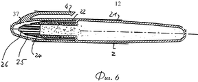
В соответствии с четвертым вариантом осуществления, показанным на фиг.6 и 7, аппликатор представляет собой неповоротный элемент 37, изготовленный, например, из меха. Неповоротный аппликатор 37 изготовлен в виде пористого аппликатора 27 или в виде проницаемого аппликатора 24 (фиг.6). В случае проницаемого аппликационного элемента 24, показанного на фиг.6, могут быть предусмотрены продольные каналы 25, ориентированные в направлении длины аппликатора 24. Необходимо отметить, что проницаемый канальный аппликатор 24 также снабжен сужающимся кончиком 26.According to a fourth embodiment shown in FIGS. 6 and 7, the applicator is a fixed
Следует отметить, что в вариантах осуществления согласно фиг.6 и 7 также может быть предусмотрено клапанное устройство, например, подобное показанному на фиг.1-4.It should be noted that in the embodiments of FIGS. 6 and 7, a valve device may also be provided, for example similar to that shown in FIGS. 1-4.
На фиг.7 показано незначительное изменение варианта осуществления на фиг.6, заключающееся в том, что проницаемый канальный аппликатор 24 заменен пористым аппликатором 27. Следует отметить, что размер пор задают таким, чтобы поры не закупоривались корректирующей средой и особенно любыми твердыми частицами в корректирующей среде, размещенной в баллончике 3. Задний конец пористого аппликатора 27 снабжен клапанным элементом 28, взаимодействующим с коническим седлом 29 для образования клапанного устройства. Когда пористый аппликатор 27 прижимают к поверхности подложки, аппликатор незначительно смещается назад, чтобы открыть клапанное устройство, образованное коническим седлом 29 и клапанным элементом 28, прикрепленным к аппликатору 27, а кроме того, вследствие эластичных свойств пористого аппликатора 27 ширина сужающегося кончика 26 будет возрастать в зависимости от давления, действующего на раздаточное устройство 1 и, следовательно, на аппликатор 27.Fig.7 shows a slight change in the embodiment of Fig.6, namely, that the
Перечень условных обозначений:List of conventions:
1 - раздаточное устройство1 - distributing device
2 - корпус2 - case
3 - баллончик для корректирующих частиц, диспергированных в текучей среде3 - spray can for corrective particles dispersed in a fluid
4 - колпачок4 - cap
5 - проход5 - passage
6 - сужающийся проход6 - tapering passage
7 - пружина7 - spring
8 - гнездо пружины8 - spring socket
9 - промежуточный ролик9 - an intermediate roller
10 - несущая ось элемента 9 (смещаемая с преодолением сопротивления пружины 7)10 - bearing axis of the element 9 (displaced with overcoming the resistance of the spring 7)
11 - аппликационный ролик11 - application roller
12 - аппликационный транспортер12 - application conveyor
14 - передний ролик элемента 1214 -
15 - лента транспортера15 - conveyor belt
16 - несущая ось элемента 1316 - bearing axis of the
17 - несущая ось элемента 1417 - bearing axis of the
18 - коническое седло18 - conical seat
19 - несущая ось элемента 1119 - bearing axis of the
20 - сужающая внешняя поверхность элемента 1120 - narrowing the outer surface of the
21 - винтовой картридж21 - screw cartridge
22 - основная часть22 - the main part
23 - винтовая резьба23 - screw thread
24 - проницаемый аппликационный элемент24 - permeable application element
25 - продольные каналы25 - longitudinal channels
26 - сужающийся кончик элемента 2426 - tapering tip of the
27 - пористый аппликатор27 - porous applicator
28 - клапан28 - valve
29 - коническое седло29 - conical seat
30 - неэластичный тороидальный аппликатор30 - inelastic toroidal applicator
31 - заостренная периферия элемента 3031 - pointed periphery of the
32 - уплотнение32 - seal
33 - заостренный кончик33 - pointed tip
34 - скошенный край34 - beveled edge
35 - согласованная выемка элемента 935 - consistent recess element 9
36 - фиксированная несущая ось элемента 3036 - fixed bearing axis of the
37 - неповоротный аппликатор37 - fixed applicator
Claims (24)
Applications Claiming Priority (2)
| Application Number | Priority Date | Filing Date | Title |
|---|---|---|---|
| EP00103992 | 2000-02-25 | ||
| EP00103992.4 | 2000-02-25 |
Publications (2)
| Publication Number | Publication Date |
|---|---|
| RU2002125499A RU2002125499A (en) | 2004-03-27 |
| RU2264298C2 true RU2264298C2 (en) | 2005-11-20 |
Family
ID=8167959
Family Applications (1)
| Application Number | Title | Priority Date | Filing Date |
|---|---|---|---|
| RU2002125499/12A RU2264298C2 (en) | 2000-02-25 | 2001-02-12 | Hand spreader for application of fluid correcting medium to surface of backing |
Country Status (15)
| Country | Link |
|---|---|
| US (1) | US6729788B2 (en) |
| EP (2) | EP1535754A3 (en) |
| JP (1) | JP2003523856A (en) |
| KR (1) | KR100724734B1 (en) |
| CN (1) | CN1162282C (en) |
| AT (1) | ATE307728T1 (en) |
| AU (1) | AU767404B2 (en) |
| BR (1) | BR0108699B1 (en) |
| CA (1) | CA2400156C (en) |
| DE (1) | DE60114372T2 (en) |
| ES (1) | ES2250352T3 (en) |
| MX (1) | MXPA02008027A (en) |
| RU (1) | RU2264298C2 (en) |
| WO (1) | WO2001062519A1 (en) |
| ZA (1) | ZA200205559B (en) |
Cited By (1)
| Publication number | Priority date | Publication date | Assignee | Title |
|---|---|---|---|---|
| RU2592790C1 (en) * | 2012-06-25 | 2016-07-27 | 3М Инновейтив Пропертиз Компани | Device for application of coating on profiled surfaces |
Families Citing this family (20)
| Publication number | Priority date | Publication date | Assignee | Title |
|---|---|---|---|---|
| US6488429B2 (en) | 2000-02-14 | 2002-12-03 | George W. Korper | Pressure modulated free ink marker for producing variable line width |
| US7422389B2 (en) * | 2002-08-30 | 2008-09-09 | L'oreal | Device for packaging and application of a product, in particular an eyeliner |
| KR20040091873A (en) * | 2003-04-22 | 2004-11-02 | 오의진 | The amendment pen that effuses paint with roller |
| FR2899075B1 (en) * | 2006-03-31 | 2008-11-21 | Oreal | APPLICATOR AND DEVICE FOR PACKAGING AND APPLICATION. |
| US8262592B1 (en) | 2007-12-27 | 2012-09-11 | Brooks Ray G | Fluid dispenser |
| CN102209640B (en) | 2008-11-11 | 2014-03-19 | 株式会社樱花彩色笔 | Applicator tip and applicator |
| US8540449B2 (en) * | 2010-03-12 | 2013-09-24 | S & P World Ltd. | Fluid-material spread apparatus having double roller |
| US8757914B1 (en) | 2013-03-15 | 2014-06-24 | BlokRok, Inc. | Apparatus and method for dispensing a fluid |
| WO2015038988A1 (en) | 2013-09-13 | 2015-03-19 | Modern Meadow, Inc. | Edible and animal-product-free microcarriers for engineered meat |
| JP5566518B1 (en) * | 2013-10-08 | 2014-08-06 | 株式会社トキワ | Cosmetic container with application body |
| CN113575862A (en) | 2014-02-05 | 2021-11-02 | 福克和谷德公司 | Dried food product made from cultured muscle cells |
| US9468279B2 (en) | 2014-04-21 | 2016-10-18 | BlokRok, Inc. | Apparatus and method for dispensing a fluid |
| ES2842501T5 (en) | 2015-09-21 | 2023-04-13 | Modern Meadow Inc | Fiber Reinforced Fabric Composite Materials |
| US11542374B2 (en) | 2016-02-15 | 2023-01-03 | Modern Meadow, Inc. | Composite biofabricated material |
| AU2017202020A1 (en) | 2016-03-25 | 2017-10-12 | BlokRok, Inc. | Apparatus and method for dispensing fluid |
| JP7007695B2 (en) * | 2016-07-04 | 2022-01-25 | 株式会社トキワ | Cosmetic container with application body |
| AU2018253595A1 (en) | 2017-11-13 | 2019-05-30 | Modern Meadow, Inc. | Biofabricated leather articles having zonal properties |
| CN113286864A (en) | 2019-01-17 | 2021-08-20 | 现代牧场股份有限公司 | Layered collagen material and preparation method thereof |
| EP3760452A1 (en) | 2019-07-04 | 2021-01-06 | Société BIC | Marker for variable shading under pressure |
| KR102196409B1 (en) * | 2020-09-24 | 2020-12-30 | 노브랜드(주) | Function roller correction pen |
Family Cites Families (32)
| Publication number | Priority date | Publication date | Assignee | Title |
|---|---|---|---|---|
| FR710720A (en) * | 1930-05-03 | 1931-08-28 | Dispensing container for liquid, pasty or other materials | |
| DE854169C (en) * | 1951-07-14 | 1952-10-30 | Anneliese Kromberg | Device, especially handheld device for applying glue or the like. |
| US3917419A (en) * | 1974-04-25 | 1975-11-04 | Kabushikikaisha Itoya | Hand operating device for drawing a line |
| DE3121948A1 (en) * | 1981-06-03 | 1982-12-23 | Ideee Design Gmbh, 5600 Wuppertal | Correction pen |
| US4511273A (en) | 1982-09-28 | 1985-04-16 | The Gillette Company | Correction fluid dispenser having a retractable and lockable sealing tip |
| US4572691A (en) | 1984-07-02 | 1986-02-25 | Minnesota Mining And Manufacturing Company | Pen-like instrument for applying correction fluid |
| US4723860A (en) * | 1985-04-15 | 1988-02-09 | Lever Brothers Company | Spring-loaded oval roller dispensing package |
| US4685820A (en) | 1985-06-05 | 1987-08-11 | Pittway Corporation | Applicator device |
| US4812071A (en) | 1986-08-27 | 1989-03-14 | Batra Pran | Correction fluid pen |
| US4923317A (en) | 1987-03-04 | 1990-05-08 | Avery International Corporation | Brushless white-out correcting fluid applicator |
| US4813463A (en) | 1987-07-22 | 1989-03-21 | Huang Chen Correction Fluid Industry Co. Ltd. | Instantly applicable correction fluid container structure |
| US4917521A (en) | 1989-02-15 | 1990-04-17 | Lai Kung Chung | Pen type container for correction fluid with daubing function |
| US5261755A (en) | 1990-05-25 | 1993-11-16 | The Gillette Company | Fluid dispenser |
| GB9021587D0 (en) * | 1990-10-04 | 1990-11-21 | Gallagher B | Stock material visual identification device |
| US5056949A (en) | 1990-10-05 | 1991-10-15 | The Gillette Company | Correction fluid dispenser with ball valve |
| US5109798A (en) * | 1990-11-23 | 1992-05-05 | Frank Impastato | Food supplement dispensing system for animals |
| US5123766A (en) | 1991-05-14 | 1992-06-23 | Charles Babiak | Correction fluid dispensing pen |
| KR930021412A (en) | 1992-04-02 | 1993-11-22 | 이시카와 히데아키 | Modifier |
| US5338775A (en) | 1992-05-19 | 1994-08-16 | The Gillette Company | Correction fluid |
| FR2701364B1 (en) * | 1993-02-10 | 1995-04-21 | Oreal | Applicator assembly for a makeup product. |
| US5499881A (en) | 1994-04-05 | 1996-03-19 | Chang; Pei-Sheng | Writing implement with correction supply |
| US5480250A (en) * | 1994-04-08 | 1996-01-02 | Birden; Donald | Dispenser with rigid open pore nib |
| US5957609A (en) * | 1994-08-19 | 1999-09-28 | Mitsubishi Pencil Kabushiki Kaisha | Applicator |
| GB9422906D0 (en) * | 1994-11-14 | 1995-01-04 | Gillette Co | Writing/marking instrument |
| US5888007A (en) | 1994-11-14 | 1999-03-30 | The Gillette Company | Marking instrument |
| JP2862488B2 (en) | 1995-01-11 | 1999-03-03 | 三菱鉛筆株式会社 | Applicator |
| CA2177210C (en) | 1995-06-07 | 1999-08-31 | Rodney J. Baudino | Off-center point marker tip |
| DE59602026D1 (en) | 1995-10-20 | 1999-07-01 | Kores Holding Zug Ag | COLOR APPLICATION PEN CORRECTIONAL LIQUID |
| DE19617777A1 (en) * | 1996-05-03 | 1997-11-06 | Ahrens Hans Joachim | Correcting pen for correcting fluids, nail polishes etc |
| WO1998042187A1 (en) * | 1997-03-24 | 1998-10-01 | Green Management Limited | Apparatus for the selective application of liquid media |
| US6004057A (en) * | 1997-11-24 | 1999-12-21 | Fulop; Jacqueline I. | Marking and eradicating instrument and method of use of same |
| US6312180B1 (en) * | 1998-04-23 | 2001-11-06 | The Gillette Company | Applicator for correction fluid |
-
2001
- 2001-02-12 CA CA002400156A patent/CA2400156C/en not_active Expired - Fee Related
- 2001-02-12 ES ES01903752T patent/ES2250352T3/en not_active Expired - Lifetime
- 2001-02-12 MX MXPA02008027A patent/MXPA02008027A/en active IP Right Grant
- 2001-02-12 BR BRPI0108699-5A patent/BR0108699B1/en not_active IP Right Cessation
- 2001-02-12 AT AT01903752T patent/ATE307728T1/en not_active IP Right Cessation
- 2001-02-12 DE DE60114372T patent/DE60114372T2/en not_active Expired - Fee Related
- 2001-02-12 WO PCT/EP2001/001531 patent/WO2001062519A1/en active IP Right Grant
- 2001-02-12 RU RU2002125499/12A patent/RU2264298C2/en not_active IP Right Cessation
- 2001-02-12 EP EP05003292A patent/EP1535754A3/en not_active Withdrawn
- 2001-02-12 EP EP01903752A patent/EP1257424B1/en not_active Expired - Lifetime
- 2001-02-12 CN CNB018048412A patent/CN1162282C/en not_active Expired - Fee Related
- 2001-02-12 JP JP2001561549A patent/JP2003523856A/en not_active Withdrawn
- 2001-02-12 AU AU31736/01A patent/AU767404B2/en not_active Ceased
- 2001-02-12 KR KR1020027011193A patent/KR100724734B1/en not_active IP Right Cessation
-
2002
- 2002-07-11 ZA ZA200205559A patent/ZA200205559B/en unknown
- 2002-08-23 US US10/226,238 patent/US6729788B2/en not_active Expired - Fee Related
Cited By (2)
| Publication number | Priority date | Publication date | Assignee | Title |
|---|---|---|---|---|
| RU2592790C1 (en) * | 2012-06-25 | 2016-07-27 | 3М Инновейтив Пропертиз Компани | Device for application of coating on profiled surfaces |
| RU2592790C9 (en) * | 2012-06-25 | 2017-07-06 | 3М Инновейтив Пропертиз Компани | Device for application of coating on profiled surfaces |
Also Published As
| Publication number | Publication date |
|---|---|
| CN1400941A (en) | 2003-03-05 |
| AU3173601A (en) | 2001-09-03 |
| ZA200205559B (en) | 2003-07-11 |
| BR0108699A (en) | 2002-12-10 |
| AU767404B2 (en) | 2003-11-06 |
| EP1257424B1 (en) | 2005-10-26 |
| KR20020083164A (en) | 2002-11-01 |
| KR100724734B1 (en) | 2007-06-04 |
| RU2002125499A (en) | 2004-03-27 |
| US20030031500A1 (en) | 2003-02-13 |
| BR0108699B1 (en) | 2010-05-04 |
| EP1535754A3 (en) | 2007-10-03 |
| ES2250352T3 (en) | 2006-04-16 |
| CN1162282C (en) | 2004-08-18 |
| JP2003523856A (en) | 2003-08-12 |
| DE60114372D1 (en) | 2005-12-01 |
| US6729788B2 (en) | 2004-05-04 |
| MXPA02008027A (en) | 2002-11-29 |
| EP1257424A1 (en) | 2002-11-20 |
| CA2400156A1 (en) | 2001-08-30 |
| EP1535754A2 (en) | 2005-06-01 |
| WO2001062519A1 (en) | 2001-08-30 |
| CA2400156C (en) | 2008-12-23 |
| ATE307728T1 (en) | 2005-11-15 |
| DE60114372T2 (en) | 2006-07-27 |
Similar Documents
| Publication | Publication Date | Title |
|---|---|---|
| RU2264298C2 (en) | Hand spreader for application of fluid correcting medium to surface of backing | |
| EP2566630B1 (en) | Liquid applicator device | |
| CA2767743C (en) | Liquid applicator device | |
| EP2825393B1 (en) | Precision liquid applicator | |
| RU2152338C1 (en) | Folding bag unit and liquid metering device | |
| CN109937146B (en) | Retractable liquid applicator device | |
| US20090103968A1 (en) | Liquid applicator | |
| US7182538B2 (en) | Paint dispensing and storage kit | |
| US20140119808A1 (en) | Wide area coating applicator | |
| EP0257931A1 (en) | Liquid dispenser, particularly for dispensing correction fluid |
Legal Events
| Date | Code | Title | Description |
|---|---|---|---|
| MM4A | The patent is invalid due to non-payment of fees |
Effective date: 20110213 |