RU2251819C2 - Inserting additional data in coded signal - Google Patents
Inserting additional data in coded signal Download PDFInfo
- Publication number
- RU2251819C2 RU2251819C2 RU2000125744/09A RU2000125744A RU2251819C2 RU 2251819 C2 RU2251819 C2 RU 2251819C2 RU 2000125744/09 A RU2000125744/09 A RU 2000125744/09A RU 2000125744 A RU2000125744 A RU 2000125744A RU 2251819 C2 RU2251819 C2 RU 2251819C2
- Authority
- RU
- Russia
- Prior art keywords
- signal
- additional data
- dsd
- prediction filter
- bit
- Prior art date
Links
Images
Classifications
-
- H—ELECTRICITY
- H04—ELECTRIC COMMUNICATION TECHNIQUE
- H04N—PICTORIAL COMMUNICATION, e.g. TELEVISION
- H04N21/00—Selective content distribution, e.g. interactive television or video on demand [VOD]
- H04N21/20—Servers specifically adapted for the distribution of content, e.g. VOD servers; Operations thereof
- H04N21/23—Processing of content or additional data; Elementary server operations; Server middleware
- H04N21/236—Assembling of a multiplex stream, e.g. transport stream, by combining a video stream with other content or additional data, e.g. inserting a URL [Uniform Resource Locator] into a video stream, multiplexing software data into a video stream; Remultiplexing of multiplex streams; Insertion of stuffing bits into the multiplex stream, e.g. to obtain a constant bit-rate; Assembling of a packetised elementary stream
-
- H—ELECTRICITY
- H03—ELECTRONIC CIRCUITRY
- H03M—CODING; DECODING; CODE CONVERSION IN GENERAL
- H03M7/00—Conversion of a code where information is represented by a given sequence or number of digits to a code where the same, similar or subset of information is represented by a different sequence or number of digits
-
- H—ELECTRICITY
- H04—ELECTRIC COMMUNICATION TECHNIQUE
- H04N—PICTORIAL COMMUNICATION, e.g. TELEVISION
- H04N21/00—Selective content distribution, e.g. interactive television or video on demand [VOD]
- H04N21/20—Servers specifically adapted for the distribution of content, e.g. VOD servers; Operations thereof
- H04N21/23—Processing of content or additional data; Elementary server operations; Server middleware
- H04N21/236—Assembling of a multiplex stream, e.g. transport stream, by combining a video stream with other content or additional data, e.g. inserting a URL [Uniform Resource Locator] into a video stream, multiplexing software data into a video stream; Remultiplexing of multiplex streams; Insertion of stuffing bits into the multiplex stream, e.g. to obtain a constant bit-rate; Assembling of a packetised elementary stream
- H04N21/2362—Generation or processing of Service Information [SI]
Abstract
Description
Настоящее изобретение относится к устройству и способу вставки дополнительных данных в кодированный сигнал.The present invention relates to a device and method for inserting additional data into an encoded signal.
Существует растущая потребность включения дополнительных данных в кодированные данные, такие как кодированные аудио- и видеосигналы, предпочтительно без увеличения скорости передачи данных. В частности, если дополнительные данные используют в качестве "водяных знаков", их следует добавлять так, чтобы они были невидимы при восприятии. "Водяные знаки" могут содержать информацию, например, об источнике документов и аудиовизуальных программ или состоянии авторских прав на них. Они могут использоваться для юридической защиты владельца авторских прав и позволяют отслеживать пиратское использование и поддерживать защиту интеллектуальной собственности.There is a growing need to include additional data in encoded data, such as encoded audio and video signals, preferably without increasing the data rate. In particular, if additional data is used as “watermarks”, they should be added so that they are invisible to perception. "Watermarks" may contain information, for example, about the source of documents and audiovisual programs or the state of copyright in them. They can be used to provide legal protection for the copyright holder and can track pirated use and support intellectual property protection.
Например, в формате супераудиокомпакт-дисков (САКД) используется кодирование без потерь (КБП) для увеличения вдвое эффективности использования данных на диске. Кодер без потерь необходим для того, чтобы обеспечить время воспроизведения многоканальной аудиоинформации до 74 минут с качеством САКД. Как подчеркивают слова "кодирование без потерь", требуемый объем памяти для любых данных значительно уменьшается таким образом, что после декодирования исходный сигнал воспроизводится с идентичностью до бита. Такой кодер или декодер описан, например, в публикации Фонса Брюкерса, Вернера Оумена, Рене ван дер Влейтена, Леона ван дер Керкхофа "Усовершенствованное кодирование без потерь однобитовых аудиосигналов" ("Improved Lossless Coding of 1-Bit Audio Signals", by Fons Bruekers, Werner Oomen, Rene van der Vieuten, Leon van der Kerkhof), сигнальный экземпляр №4563(I-6), представленный на 103-м съезде Общества инженеров по звуковой технике (ОИЗТ), проходившем 26-29 сентября 1997 г. в Нью-Йорке. Кодирование осуществляют путем деления потока входных данных на кадры и определения набора оптимизированных параметров для каждого кадра. Часть этих параметров выдается для предсказания с целью устранения избыточностей. Разность между исходным сигналом и предсказанным сигналом, которую называют остаточным сигналом, содержит значительно меньше уместной информации, если можно найти "хорошие" параметры предсказания. Когда возникает необходимость кодирования без потерь, нельзя не учитывать остаточный сигнал, но если он содержит мало уместной информации, его можно очень эффективно подвергнуть статистическому кодированию, используя другую часть оптимизированных параметров. Поскольку в наборе параметров сохраняется избыточная информация, этот набор параметров, а также подвергнутый статическому кодированию остаточный сигнал, запоминают, т.к. они нужны для кодирования без потерь.For example, in the Super Audio CD format (SACD), lossless coding (KBP) is used to double the efficiency of using data on a disk. A lossless encoder is necessary in order to provide a multi-channel audio information playback time of up to 74 minutes with SACD quality. As the words “lossless coding” emphasize, the required memory size for any data is significantly reduced so that after decoding, the original signal is reproduced with identity up to a bit. Such an encoder or decoder is described, for example, in the publication Improved Lossless Coding of 1-Bit Audio Signals, by Fons Bruekers Werner Oomen, Rene van der Vieuten, Leon van der Kerkhof), signal instance No. 4563 (I-6), presented at the 103rd congress of the Society of Sound Engineers (OIZT), held on September 26-29, 1997 in New York. Coding is carried out by dividing the input data stream into frames and determining a set of optimized parameters for each frame. Some of these parameters are issued for prediction in order to eliminate redundancies. The difference between the original signal and the predicted signal, which is called the residual signal, contains significantly less relevant information if you can find "good" prediction parameters. When there is a need for lossless coding, one cannot ignore the residual signal, but if it contains little relevant information, it can be very efficiently subjected to statistical coding using another part of the optimized parameters. Since redundant information is stored in the parameter set, this parameter set, as well as the residual signal subjected to the static encoding, are stored, because they are needed for lossless coding.
Если необходима дополнительная информация, например в целях "вставки водяных знаков", то ее можно добавлять, как широко известно, путем добавления ее в исходный сигнал таким образом, что изменение сигнала будет незаметным для слушателя. Сигнал, измененный подобным образом, больше нельзя рассматривать как (побитно достоверный) исходный сигнал. Кроме того, этот тип "вставки водяных знаков" имеет недостаток, заключающийся в том, что невозможно обнаружить "водяные знаки", присутствующие в кодированном сигнале, при отсутствии декодирования без потерь. По причинам простоты декодера "водяных знаков", желательно иметь выбор для обнаружения "водяных знаков" до декодирования без потерь.If additional information is needed, for example, for the purpose of "inserting watermarks", it can be added, as is widely known, by adding it to the original signal so that the change in the signal will be invisible to the listener. A signal that is modified in this way can no longer be regarded as a (bit-by-bit reliable) source signal. In addition, this type of “watermark insertion” has the disadvantage that it is not possible to detect “watermarks” present in the encoded signal in the absence of lossless decoding. For reasons of simplicity of the watermark decoder, it is desirable to have a choice for detecting watermarks before lossless decoding.
Задача настоящего изобретения заключается в том, чтобы разработать устройство и способ вставки дополнительных данных в кодированный информационный сигнал, которые обеспечивают считывание дополнительных данных без декодирования всего сигнала и не влияют на качество музыки.The objective of the present invention is to develop a device and method for inserting additional data into an encoded information signal that provides the reading of additional data without decoding the entire signal and does not affect the quality of music.
С этой целью, способ, соответствующий изобретению, отличается тем, что для вставки дополнительных данных вставляют в данные дополнительную информацию, а вспомогательную информацию, необходимую для кодирования дополнительных данных, получают из других данных, доступных в процессе кодирования.To this end, the method according to the invention is characterized in that additional information is inserted into the data to insert additional data, and auxiliary information necessary for encoding the additional data is obtained from other data available in the encoding process.
Преимущество настоящего изобретения состоит в том, что из-за вставки данных в кодируемые данные нельзя удалить дополнительную информацию без искажения содержимого кодированного сигнала. Вспомогательную информацию, необходимую для кодирования дополнительных данных, получают из других данных, доступных в процессе кодирования, и эту вспомогательную информацию для кодирования дополнительных данных не нужно записывать или запоминать для последующего процесса декодирования. Таким образом, этот способ очень экономичен в отношении скорости передачи битов.An advantage of the present invention is that due to the insertion of data into the encoded data, additional information cannot be deleted without distorting the contents of the encoded signal. The auxiliary information necessary for encoding additional data is obtained from other data available in the encoding process, and this auxiliary information for encoding additional data does not need to be recorded or stored for the subsequent decoding process. Thus, this method is very economical in terms of bit rate.
Другая задача изобретения состоит в том, чтобы разработать альтернативу первому решению.Another object of the invention is to develop an alternative to the first solution.
С этой целью, далее способ, соответствующий изобретению, отличается тем, что для вставки дополнительных данных воздействуют на набор параметров дополнительными данными. Таким образом, для считывания "водяного знака" нужно декодировать не все из полных данных, а лишь часть данных, в которой содержатся параметры, используемые для кодирования и/или декодирования. Поскольку дополнительную информацию вставляют в набор параметров, не нужно тратить дополнительный бит для этой информации.For this purpose, further, the method according to the invention is characterized in that additional data is applied to the parameter set to insert additional data. Thus, to read the “watermark”, not all of the complete data needs to be decoded, but only the part of the data that contains the parameters used for encoding and / or decoding. Since additional information is inserted into the parameter set, it is not necessary to spend an additional bit for this information.
Дополнительную информацию можно вставлять путем выбора четного или нечетного числа параметров или путем выбора наименьшего значащего бита, например первого параметра. Например, четное число параметров представляет значение "1" бита "водяного знака", а нечетное число параметров представляет значение "0" бита "водяного знака".Additional information can be inserted by selecting an even or odd number of parameters, or by selecting the least significant bit, for example, the first parameter. For example, an even number of parameters represents a “1” watermark bit value, and an odd number of parameters represents a “0” watermark bit value.
Преимущество изобретения вытекает из того, что, по практическим причинам (вычислительные возможности, затраты и т.д.), для кодирования определяют не наилучший набор параметров, а "целесообразно хороший" набор параметров. Следовательно, эти алгоритмы, как правило, предназначены для работы с субоптимальным набором параметров. Таким образом, малые изменения в наборе параметров, подобные изменению наименьшего значащего бита параметра, добавлению фиктивного параметра для достижения нечетного или четного числа параметров, или вносимые каждый раз, когда необходимо вставить бит "водяного знака" или даже не учитывать параметр, чтобы достичь нечетного или четного числа параметров, не будут оказывать большое влияние на эффективность кодирования. Иногда такое малое изменение набора параметров может даже с запасом улучшить процесс кодирования.An advantage of the invention follows from the fact that, for practical reasons (computational capabilities, costs, etc.), for encoding, it is not the best set of parameters that is determined, but a "reasonably good" set of parameters. Therefore, these algorithms are usually designed to work with a suboptimal set of parameters. Thus, small changes in the parameter set, such as changing the least significant bit of a parameter, adding a dummy parameter to achieve an odd or even number of parameters, or making it every time you need to insert a bit of a “watermark” or even not take into account a parameter to achieve an odd or an even number of parameters will not have a big impact on coding efficiency. Sometimes such a small change in the set of parameters can even improve the coding process with a margin.
Преимущество изобретения заключается в том, что если данные нужно сохранять в форме данных, кодированных без потерь, то нельзя удалить "водяные знаки" без декодирования сигнала и повторного кодирования без потерь этих данных с измененным набором параметров. Поскольку декодеру без потерь нужны все коэффициенты, пропущенный или неправильный коэффициент, который удален или изменен для исключения "водяного знака", приведет к потере сигнала на протяжении кадра для всех каналов.An advantage of the invention is that if the data needs to be stored in the form of data encoded without loss, then it is impossible to remove the "watermarks" without decoding the signal and re-encoding without loss of this data with a modified set of parameters. Since the lossless decoder needs all the coefficients, a missing or incorrect coefficient that is deleted or changed to eliminate the watermark will result in signal loss throughout the frame for all channels.
Фиг.1 изображает устройство для вставки двух независимых дополнительных данных х, у в сигнал, кодированный без потерь. Первые данные х используются для вставки информации w о "водяном знаке". Поскольку длина "водяного знака" w больше, чем у информации, которую можно было бы запомнить с помощью дополнительных данных, "водяной знак" w упаковывается генератором 1 упаковки в транспортный пакет, который обеспечивает вставку битов пачки данных типа последовательного сигнала. Посредством синхрокомбинации, включенной в заголовок транспортного пакета, можно легко вернуться к началу транспортного пакета. Биты х транспортного пакета побитно вставляются в сигнал, кодированный без потерь, в качестве так называемых битов Х передачи цифрового сигнала (битов Х_ПЦС).Figure 1 depicts a device for inserting two independent additional data x, y into a lossless encoded signal. The first data x is used to insert the watermark information w. Since the length of the “watermark” w is longer than that of information that could be remembered using additional data, the “watermark” w is packed by the
Вторые данные у вставляют в виде так называемых битов Y передачи цифрового сигнала (битов Y_ПЦС). Вставленные биты Y_ПЦС задают равными значению "1", чтобы указать, что сигнал, кодированный без потерь, применим к современному формату. Если в будущем возникнет потребность иметь флаг, то можно использовать бит Y_ПЦС. Должно быть очевидно для квалифицированных специалистов в данной области техники, что бит Y_ПЦС можно также использовать в других системах записи в форме потока структурированных данных для вставки информации, которая имеет длину больше одного бита.The second data, y, is inserted in the form of the so-called digital signal transmission bits Y (bits Y_ПЦС). The inserted Y_SPC bits are set to "1" to indicate that the lossless encoded signal is applicable to the current format. If in the future there is a need to have a flag, then you can use the bit Y_ПЦС. It should be apparent to those skilled in the art that the Y_SPC bit can also be used in other recording systems in the form of a structured data stream to insert information that is longer than one bit.
Чтобы закодировать потоки параллельных данных, которые называют каналами С0... Сn-1 данных, стерео- или многоканальные записи прямого потока данных (DSD-записи) делят на кадры. В конкретном варианте осуществления изобретения используют семьдесят пять кадров в секунду для каждого канала Ci. Хотя скорость передачи данных сигнала w "водяного знака" зависит от скорости передачи кадров, изобретение не ограничивается какой-либо конкретной скоростью передачи кадров.To encode parallel data streams called channels C 0 ... C n-1 data, stereo or multichannel direct data stream recordings (DSD records) are divided into frames. In a particular embodiment, seventy-five frames per second are used for each channel C i . Although the data rate of the watermark signal w depends on the frame rate, the invention is not limited to any particular frame rate.
Для каждого кадра управляющее устройство, которое не показано, так как оно не является частью изобретения, распознает, какой режим используется для кодирования: простой режим кодирования без потерь (КБП) или кодированный режим КБП. Простой режим КБП используют в исключительных случаях, если коэффициент сжатия кадра недостаточен, а кадр фактически содержит простой DSD.For each frame, a control device, which is not shown, since it is not part of the invention, recognizes which mode is used for encoding: a simple lossless coding mode (KBP) or encoded KBP mode. Simple mode KBU is used in exceptional cases, if the compression ratio of the frame is insufficient, and the frame actually contains a simple DSD.
Выбранный алгоритм КБП создан на основе фильтра с предсказанием и таблицы вероятностей. Для оптимизации коэффициента сжатия блок 4 управления параметрами снова анализирует отдельно каждый кадр каждого канала. Блок 4 управления параметрами вычисляет для каждого канала Ci набор Ai=ai(1)... ai(ki) коэффициентов фильтра с предсказанием для каждого фильтра с предсказанием и набор Пi=π i(1)... π i(mi) коэффициентов таблицы вероятностей для каждой таблицы вероятностей. В конкретном варианте осуществления изобретения длина коэффициента аi фильтра с предсказанием составляет девять битов, тогда как число ki коэффициентов фильтра с предсказанием изменяется, но ограничено максимальным значением 128. Каждый коэффициент 711 таблицы вероятностей имеет длину семь битов. Число mi коэффициентов таблицы вероятностей также изменяется, но ограничено максимальным значением шестьдесят четыре. Как правило, оно составляет от тридцати двух до шестидесяти четырех. Эти числа приведены в качестве примеров и представляют собой числа, которые, как обнаружилось, дают наилучшие результаты для аудиосигналов, но не следует считать, что изобретение ограничивается этими числами. Конечно, эти числа зависят от скорости передачи кадров, алгоритма фильтрации с предсказанием и содержимого сигнала источника. Однако, можно было бы найти и другие числа, обеспечивающие больший коэффициент cжатия.The selected KBP algorithm is based on a prediction filter and a probability table. To optimize the compression ratio, the parameter control unit 4 again analyzes each frame of each channel separately. Parameter control unit 4 calculates for each channel C i a set of A i = a i (1) ... a i (k i ) prediction filter coefficients for each prediction filter and a set П i = π i (1) ... π i (m i ) of the coefficients of the probability table for each probability table. In a particular embodiment, the length of the prediction filter coefficient a i is nine bits, while the number k i of prediction filter coefficients varies, but is limited to a maximum value of 128. Each probability table coefficient 711 has a length of seven bits. The number m i of coefficients in the probability table also varies, but is limited to a maximum of sixty-four. As a rule, it is from thirty two to sixty four. These numbers are given as examples and are numbers that have been found to give the best results for audio signals, but should not be considered that the invention is limited to these numbers. Of course, these numbers depend on the frame rate, the prediction filtering algorithm, and the contents of the source signal. However, one could find other numbers that provide a higher compression ratio.
Определение оптимальных коэффициентов а, π затруднено и требует значительной вычислительной мощности. Поэтому находят компромисс для выбора как раз "целесообразно хорошего" набора коэффициентов. Поскольку для каждого канала Ci вычисляется отдельный набор Ai, Пi коэффициентов, то наборы коэффициентов, используемых для каждого канала, будут отличаться друг от друга, но не обязательно отличаться в каждом случае.The determination of the optimal coefficients a, π is difficult and requires significant computing power. Therefore, a compromise is found for choosing just the “reasonably good” set of coefficients. Since for each channel C i a separate set of A i , П i coefficients is calculated, the sets of coefficients used for each channel will be different from each other, but not necessarily different in each case.
Для вставки бита Y_ПЦС в кадр генератор 3 флагов изменяет наименьший значащий бит НЗБ первого коэффициента а0 (1) фильтра. Как уже упоминалось выше, небольшое изменение коэффициентов фильтра не должно вызывать значительное ухудшение в проведении кодирования.To insert the Y_CPC bit into the frame, the flag generator 3 changes the least significant bit of the NZB of the first filter coefficient a 0 (1). As mentioned above, a small change in the filter coefficients should not cause a significant deterioration in the encoding.
Все коэффициенты наборов А и П, включая измененный коэффициент а0 (1), являются значимыми для кодированного сигнала и поэтому должны быть записаны для процесса считывания или декодирования, который будет проведен позже. Поскольку все наборы А, а также П, коэффициентов по-прежнему имеют некоторую избыточность, то для генерации сжатых слоев А’, П’ данных используют первый 5 и второй 6 блоки сжатия. Предпочтительно используют алгоритм сжатия, который обеспечивает соответствующую декомпрессию слов А’ и П’ наиболее простым образом с тем, чтобы можно было без больших усилий проводить считывание вставленного бита Y_ПЦС.All coefficients of the sets A and P, including the modified coefficient a 0 (1), are significant for the encoded signal and therefore must be recorded for the reading or decoding process, which will be carried out later. Since all sets of A, as well as P, coefficients still have some redundancy, then the first 5 and second 6 compression blocks are used to generate compressed data layers A ', P'. Preferably, a compression algorithm is used that provides the corresponding decompression of the words A 'and P' in the simplest way so that it is possible to read the inserted Y_SCC bit without great effort.
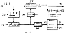
Также важно, чтобы для кодирования без потерь использовались коэффициенты, значения которых изменены, а не исходные оцененные коэффициенты. В противном случае будет ухудшаться процесс декодирования. В этом конкретном варианте осуществления изобретения функцию декодера без потерь делят между собой блок 7 предсказания кодирования для каждого канала Ci и арифметический кодер 9, который является общим для всех блоков 7 предсказания кодирования. Структура блока 7 предсказания кодирования изображена на фиг.2.It is also important that coefficients whose values are changed, rather than the original estimated coefficients, be used for lossless coding. Otherwise, the decoding process will deteriorate. In this particular embodiment of the invention, the lossless decoder function is divided among themselves by an encoding prediction unit 7 for each channel C i and an arithmetic encoder 9, which is common to all encoding prediction units 7. The structure of the coding prediction unit 7 is shown in FIG.
Блок 7 предсказания кодирования содержит фильтр 71 с предсказанием, который инициализируется соответствующим набором Ai параметров фильтра. Посредством преобразователя 72 уровня двоичный "0" входного сигнала xi преобразуется в числовое значение "-1", а двоичное значение "1" преобразуется в числовое значение "+1" перед вводом входного сигнала в фильтр 71 с предсказанием. Выходной сигнал фильтра 71 сThe encoding prediction block 7 comprises a
предсказанием квантуется первым и вторым квантователями 73, 74. Выходной сигнал первого квантователя 73 подвергается логической операции "исключающее ИЛИ" вместе со входным сигналом посредством логического элемента 75 "исключающее ИЛИ" и образует остаточный сигнал ei, который является первым из двух выходных сигналов блока 7 предсказания кодирования. Выходной сигнал второго квантователя 74 служит в качестве индекса α i для таблицы вероятностей, запоминаемой в матрице 76. Таблица вероятностей состоит из набора Пi параметров вероятностей. Выходной сигнал матрицы 76 образует второй выходной сигнал блока 7 предсказания кодирования, т.е. сигнал pi вероятностей. Использование таблицы вероятностей более подробно описано в работе, указанной во вводной части описания.the prediction is quantized by the first and
Мультиплексор 8 осуществляет объединение остаточных сигналов е0... еn-1 в сигналы р0... рn-1 вероятностей. На один вход мультиплексора 8 также подается выходной сигнал генератора 2 "водяных знаков". Для вставки битов Х_ПЦС информации о "водяном знаке" мультиплексор 8 вставляет бит Х_ПЦС перед сигналом е. Благодаря конструкции арифметического кодера 9, коэффициент вероятности для кодирования бита Х_ПЦС, именуемый далее коэффициентом pw вероятности "водяного знака", является обязательным. Для экономии места в памяти в конкретном варианте осуществления изобретения коэффициент pw вероятности "водяного знака" получают из первого коэффициента а0 (1) фильтра с предсказанием. С этой целью первый коэффициент а0 (1) фильтра с предсказанием первого канала подают в модуль 10 вероятностей "водяных знаков". Посредством этого модуля первые семь битов коэффициента а0 (1) интерпретируются в обратном порядке как не имеющее знака интегральное число D, к которому прибавляют 1. При использовании этого полученного значения для коэффициента вероятности "водяного знака" запись коэффициента вероятности "водяного знака" становится необязательной, и дополнительный бит в блоке кодированных данных не требуется. Таким образом, вставка бита Х_ПЦС будет удлинять блок, подвергнутый КБП, лишь близко к пределу.The multiplexer 8 combines the residual signals e 0 ... e n-1 into the signals p 0 ... p n-1 probabilities. At one input of the multiplexer 8 is also fed the output signal of the generator 2 "watermark". To insert the X_CPC bits of the watermark information, the multiplexer 8 inserts the X_CPC bit before the signal e. Due to the construction of the arithmetic encoder 9, the probability coefficient for encoding the X_CPC bit, hereinafter referred to as the watermark probability coefficient p w , is mandatory. In order to save memory space in a particular embodiment of the invention, the watermark probability coefficient p w is obtained from the first prediction filter coefficient a 0 (1). To this end, the first coefficient a 0 (1) of the filter with the prediction of the first channel is supplied to the watermark probability module 10. Through this module, the first seven bits of the coefficient a 0 (1) are interpreted in reverse order as the unsigned integral number D to which one is added. When using this obtained value for the watermark probability coefficient, writing the watermark probability coefficient becomes optional , and an extra bit in the encoded data block is not required. Thus, the insertion of the bit X_PCS will extend the block subjected to the KBP, only close to the limit.
Арифметический кодер 9 генерирует сигнал кодированного DSD из сигнала е и сигнала р вероятности.Arithmetic encoder 9 generates a coded DSD signal from signal e and probability signal p.
Поскольку арифметический кодер 9 вставляет бит Х_ПЦС в качестве первого бита каждого кодируемого блока, этот бит Х_ПЦС можно не размещать в качестве одиночного бита в кодированный DSD сигнал. Следовательно, его можно удалять без декодирования кодированного DSD-сигнала. Исключение или изменение одного или нескольких битов неизбежно вызовет потерю данных всего кадра. С другой стороны, для считывания "водяного знака" достаточен простейший арифметический декодер. Следовательно, это полностью отвечает идеалу "водяного знака": трудно удалить, но легко считывать. Поэтому, хоть и не обязательно вставлять бит Х_ПЦС перед сигналом е, но он несколько упростит процесс кодирования "водяного знака", поскольку нужно будет оценивать лишь начало кодированного DSD-сигнала.Since the arithmetic encoder 9 inserts the X_PCA bit as the first bit of each encoded block, this X_PCA bit may not be allocated as a single bit in the encoded DSD signal. Therefore, it can be deleted without decoding the encoded DSD signal. Excluding or changing one or more bits will inevitably cause data loss of the entire frame. On the other hand, a simple arithmetic decoder is sufficient to read the “watermark”. Therefore, this fully meets the ideal of the “watermark”: it is difficult to remove, but easy to read. Therefore, although it is not necessary to insert the X_CPC bit before the e signal, it will somewhat simplify the watermark coding process, since only the beginning of the encoded DSD signal will need to be evaluated.
Следующая таблица изображает не детализированный синтаксис кадра, закодированного в кодированном режиме КБП (таблица 1):The following table depicts a non-detailed syntax for a frame encoded in KBP encoded mode (table 1):
В этом случае бит КБП имеет значение "1", указывая блок данных, закодированных в кодированном режиме КБП. Биты суб-блока "УПРАВЛ" содержат некоторую информацию об управлении, например такую, как число ki коэффициентов фильтра с предсказанием и число mi коэффициентов вероятностей заданного канала Ci. Следующие два суб-блока А' и П' содержат наборы А коэффициентов фильтра с предсказанием и П коэффициентов вероятностей в сжатой форме. Последний блок "КОДИРОВАННОЕ DSD" в конечном счете содержит кодированный DSD-сигнал. Как пояснялось выше, длина блоков А, П данных и блока "КОДИРОВАННЫЙ DSD" изменяется от кадра к кадру.In this case, the KBP bit is set to "1", indicating a block of data encoded in the encoded KBK mode. The bits of the “CONTROL” sub-block contain some control information, such as, for example, the number k i of prediction filter coefficients and the number m i of the probability coefficients of a given channel C i . The next two sub-blocks A 'and P' contain sets of prediction filter coefficients A and P probability coefficients in compressed form. The last block, "CODED DSD" ultimately contains the encoded DSD signal. As explained above, the length of the blocks A, P data and the block "CODED DSD" varies from frame to frame.
Блоки данных, закодированных в кодированном режиме КБП, записывают на носитель информации, например такой, как супераудиокомпакт-диск (САКД) или многоцелевой цифровой диск (МЦД, DVD). Поскольку процесс записи на носитель информации и процесс считывания с носителя информации не являются частью изобретения, и специалистам в данной области техники известно множество подходящих средств для проведения таких процессов, этот аспект здесь не описывается, а символизируется пунктирной линией 11, и соответствующий этой позиции конструктивный элемент именуется дисковым интерфейсом.Blocks of data encoded in KBP encoded mode are recorded on a storage medium, for example, such as a super audio CD (SACD) or a multi-purpose digital disk (MCD, DVD). Since the process of writing to the storage medium and the process of reading from the storage medium are not part of the invention, and specialists in the art know many suitable means for carrying out such processes, this aspect is not described here, but is symbolized by dashed line 11, and the structural element corresponding to this position called the disk interface.
В устройстве считывания, которое в конкретном варианте осуществления изобретения является устройством воспроизведения САКД или МЦД, блок данных определяется как блок, закодированный в кодированном режиме КБП, если первый бит, т.е. бит КБП, имеет значение "1". В этом случае блок данных подразделяется на блоки А', П' и "КОДИРОВАННОЕ ОСД" посредством данных, содержащихся в блоке данных управления, "УПРАВЛ". Суб-блоки А' и П' подвергают декомпрессии с помощью первого и второго блоков 12, 13 декомпрессии для восстановления наборов Аi, Пi коэффициентов. Для каждого канала предусмотрен отдельный блок 14 предсказания декодирования, причем каждый блок 14 предсказания декодирования содержит фильтр с предсказанием и таблицу вероятностей. В начале декодирования блока, закодированного в кодированном режиме КБП, загружают наборы Аi и Пi коэффициентов в подходящие фильтры с предсказанием и таблицы вероятностей блоков 14 предсказания кодирования.In a reader, which in a particular embodiment of the invention is a SACD or IDC playback device, a data block is defined as a block encoded in a PCB encoded mode if the first bit, i.e. bit KBP, has a value of "1". In this case, the data block is subdivided into blocks A ', P' and "CODED OSD" by the data contained in the control data block, "CONTROL". Sub-blocks A 'and P' are decompressed using the first and second decompression blocks 12, 13 to restore sets of A i , P i coefficients. A separate decoding prediction block 14 is provided for each channel, with each decoding prediction block 14 comprising a prediction filter and a probability table. At the beginning of the decoding of the block encoded in the KBP encoded mode, the sets A i and P i of the coefficients are loaded into suitable prediction filters and the probability tables of the encoding prediction blocks 14.
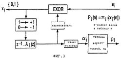
Блоки 14 предсказания декодирования также восстанавливают сигналы p0... pn-1 вероятностей, которые объединяются в сигнал р мультиплексором 15 устройства считывания. Сигнал р подается в арифметический декодер 17, который посредством сигнала р вероятности осуществляет декомпрессию данных, содержащихся в суб-блоке "КОДИРОВАННОЕ ОСД", с получением информационного потока (потока данных) е. Посредством демультиплексора 16 информационный поток е разделяют на разные остаточные сигналы е0... en-1 индивидуальных каналов и подают в блоки 14 предсказания декодирования.Decoding prediction units 14 also reconstruct probability signals p 0 ... p n-1 , which are combined into signal p by the multiplexer 15 of the reader. The signal p is supplied to an arithmetic decoder 17, which, by means of the probability signal p, decompresses the data contained in the “CODED OSD” sub-block to obtain an information stream (data stream) e. By means of a demultiplexer 16, the information stream e is divided into different residual signals e 0 ... e n-1 are individual channels and are supplied to decoding prediction blocks 14.
Конструкция блока 14 предсказания декодирования изображена на фиг.3. Остаточный сигнал ei каждого канала подается на первый вход логического элемента "Исключающее ИЛИ" суб-блока декодирования. На выходе логического элемента "Исключающее ИЛИ" формируется выходной сигнал каждого канала Ci. Этот выходной сигнал также подается в преобразователь уровня, который выполняет ту же операцию, что и преобразователь уровня в вышеописанном устройстве записи. Выходной сигнал преобразователя уровня подается в фильтр с предсказанием. Выходной сигнал фильтра подается в два квантователя. Выход первого квантователя соединен со вторым входом логического элемента "Исключающее ИЛИ", а другой выходной сигнал квантователя используется в качестве индекса α i для таблицы вероятностей, запомненной в матрице. Значения pi всех вероятностей, выбираемых по индексу α i, подаются через мультиплексор в арифметический декодер.The design of decoding prediction unit 14 is shown in FIG. The residual signal e i of each channel is supplied to the first input of the exclusive OR logic element of the decoding sub-block. The output of the exclusive OR gate is the output signal of each channel C i . This output signal is also supplied to a level converter, which performs the same operation as the level converter in the above-described recording device. The output of the level converter is supplied to the prediction filter. The output signal of the filter is supplied to two quantizers. The output of the first quantizer is connected to the second input of the XOR gate, and the other output of the quantizer is used as the index α i for the probability table stored in the matrix. The values p i of all probabilities selected by index α i are fed through a multiplexer to an arithmetic decoder.
Детектор 18 флагов используют для восстановления вставленных битов Y_ПЦС. Поскольку бит Y_ПЦС запомнен в ячейке для первого коэффициента, нужно проверять с помощью декодера 18 флагов только начало сжатого блока А'. Детектор 18 флагов осуществляет декомпрессию только начала блока А’ и осуществляет выборку первых коэффициентов а0 (1) фильтра первого канала и анализирует их наименьшие значащие биты для принятия решения о значении бита Y_ПЦС. Поскольку алгоритм сжатия блоков для блоков А и П выбран с возможностью обеспечения простой декомпрессии, детектор "водяных знаков" может быть сконструирован очень примитивно, по сравнению с декодером всего сигнала.Flags detector 18 is used to recover the inserted bits of the Y_CPC. Since the Y_SPC bit is stored in the cell for the first coefficient, it is necessary to check with the help of decoder 18 flags only the beginning of compressed block A '. The detector 18 flags decompresses only the beginning of block A 'and selects the first coefficients a 0 (1) of the filter of the first channel and analyzes their least significant bits to decide on the value of bit Y_ЦЦС. Since the block compression algorithm for blocks A and P is selected with the possibility of providing simple decompression, the watermark detector can be designed very primitively compared to the decoder of the entire signal.
Для извлечения "водяного знака" w коэффициент а0=(1), определенный детектором 18 флагов "водяных знаков", подается в модуль 19 вероятностей "водяных знаков" устройства считывания. Модуль 19 вероятностей "водяных знаков" вычисляет, как было описано для устройства записи, коэффициент pw вероятности "водяного знака". Коэффициент pw вероятности "водяного знака" подается в арифметический декодер для декодирования бита Х_ПЦС. Поскольку бит Х_ПЦС является первым битом, выдаваемым арифметическим декодером, он может быть легко извлечен детектором 20 "водяных знаков". Однако, с помощью более сложного детектора такой бит можно извлечь из сигнала всегда, когда бы ни было принято решение вставить его. Блок 21 форматирования извлекает информацию w о "водяных знаках" из битов Х_ПЦС, которые подвергнуты обратному преобразованию из потока последовательных битов в блок данных с помощью синхрокомбинации.To extract the “watermark” w, the coefficient a 0 = (1) determined by the detector 18 of the flags of the “watermarks” is supplied to the module 19 of the probabilities of the “watermarks” of the reader. The watermark probability module 19 calculates, as described for the recording device, the watermark probability coefficient p w . The watermark probability coefficient p w is supplied to an arithmetic decoder for decoding the X_PCS bit. Since the X_PCA bit is the first bit output by an arithmetic decoder, it can be easily extracted by the watermark detector 20. However, with a more sophisticated detector, such a bit can always be extracted from a signal whenever it is decided to insert it. The formatting unit 21 extracts watermark information w from the X_SPC bits, which are inversely converted from the stream of consecutive bits to a data block by synchronization.
Хотя функция обнаружения "водяных знаков" может быть встроена в другое декодирующее средство устройства считывания, эта структура показывает, что обнаружение "водяных знаков" можно проводить в отдельной ситуации. Нет необходимости декодировать весь кодированный DSD-сигнал. Следовательно, детектор 18 флагов "водяных знаков", модуль 19 вероятностей "водяных знаков", детектор 20 "водяных знаков" и блок 21 форматирования могут быть выполнены как единое целое в одном устройстве и работать без усложненных функций, встроенных в блоки 14 предсказания декодирования.Although the watermark detection function can be integrated into other decoding means of the reader, this structure indicates that watermark detection can be performed in a separate situation. There is no need to decode the entire encoded DSD signal. Therefore, the watermark flag detector 18, the watermark probability module 19, the watermark detector 20, and the formatting unit 21 can be integrally integrated in one device and operate without complicated functions embedded in the decoding prediction units 14.
Перед этим был описан кодированный режим КБП. Как описано выше, если кодирование иногда не способствует уменьшению скорости передачи битов, приходится запоминать сигнал как простой DSD-сигнал. Этот информационный режим называется простым режимом КБП и изображен ниже (таблица 2).Before this, the encoded CBP mode was described. As described above, if encoding sometimes does not help to reduce the bit rate, you have to remember the signal as a simple DSD signal. This information mode is called the KBP simple mode and is shown below (table 2).
Бит КБП задан равным значению "0", указывая, что кадр содержит простой DSD-сигнал. Бит, следующий за битом КБП, используют для запоминания бита Х_ПЦС "водяного знака" в простом формате. За битом Х_ПЦС следуют данные "Простого DSD". Это гарантирует, что каждый кодированный блок содержит бит Х_ПЦС, независимо от того, имеется ли блок "Кодированный DSD" или "Простой DSD". Это обладает тем преимуществом, что поток последовательных данных битов Х_ПЦС не зависит от формата, который используется. С другой стороны, простой бит Х_ПЦС простого DSD-сигнала действительно можно изменять без какого-либо ущерба для содержимого сигнала блока в блоке "Простой DSD". Однако, поскольку блок "Простой DSD" является исключением в огромном большинстве, будет более чем достаточно неискаженных блоков "Кодированный DSD" для того, чтобы нести информацию по всей длине "водяного знака".The KBP bit is set to "0", indicating that the frame contains a simple DSD signal. The bit following the KBP bit is used to store the watermark X_PCB bit in a simple format. The X_CPC bit is followed by "Simple DSD" data. This ensures that each coded block contains an X_SCC bit, regardless of whether there is a Coded DSD or Simple DSD block. This has the advantage that the serial data stream of the X_SPC bits is independent of the format used. On the other hand, the simple X_SCC bit of a simple DSD signal can indeed be changed without any damage to the contents of the block signal in the Simple DSD block. However, since the "Simple DSD" block is an exception in the vast majority, there will be more than enough undistorted "DSD Coded" blocks to carry information along the entire length of the "watermark".
В дополнительном конкретном варианте осуществления изобретения в сигнал, кодированный без потерь, вставляют более одного дополнительного бита путем изменения более одного наименьшего значащего бита (НЗБ) параметров. Для вставки двух битов на кадр, например, не используются первый и второй коэффициенты 31(0), 32(0) первого аудиоканала. Эти два бита можно использовать для представления следующей информации (таблица 3)In a further specific embodiment of the invention, more than one additional bit is inserted into the lossless encoded signal by changing more than one least significant bit (LSS) of the parameters. To insert two bits per frame, for example, the first and second coefficients 31 (0), 32 (0) of the first audio channel are not used. These two bits can be used to represent the following information (table 3)
Поскольку для использования в каждом кадре предусмотрен лишь один бит "водяного знака", информацию о "водяных знаках" приходится записывать в формате последовательных данных. Поэтому символ "10" синхронизации служит для обнаружения начала информации о "водяных знаках".Since only one bit of the “watermark” is provided for use in each frame, information about the “watermarks” has to be recorded in serial data format. Therefore, the synchronization symbol “10” serves to detect the start of the watermark information.
Claims (7)
Applications Claiming Priority (2)
| Application Number | Priority Date | Filing Date | Title |
|---|---|---|---|
| EP99100580.2 | 1999-01-13 | ||
| EP99100580 | 1999-01-13 |
Publications (2)
| Publication Number | Publication Date |
|---|---|
| RU2000125744A RU2000125744A (en) | 2002-09-10 |
| RU2251819C2 true RU2251819C2 (en) | 2005-05-10 |
Family
ID=8237342
Family Applications (1)
| Application Number | Title | Priority Date | Filing Date |
|---|---|---|---|
| RU2000125744/09A RU2251819C2 (en) | 1999-01-13 | 2000-01-10 | Inserting additional data in coded signal |
Country Status (15)
| Country | Link |
|---|---|
| US (1) | US7334129B1 (en) |
| EP (1) | EP1062813A1 (en) |
| JP (1) | JP4504572B2 (en) |
| KR (1) | KR100729347B1 (en) |
| CN (1) | CN1184818C (en) |
| AU (1) | AU1984100A (en) |
| BR (1) | BR0004071A (en) |
| CA (1) | CA2323561C (en) |
| ID (1) | ID26575A (en) |
| IL (1) | IL138385A (en) |
| PL (1) | PL342815A1 (en) |
| RU (1) | RU2251819C2 (en) |
| TR (1) | TR200002630T1 (en) |
| TW (1) | TW536917B (en) |
| WO (1) | WO2000042770A1 (en) |
Cited By (4)
| Publication number | Priority date | Publication date | Assignee | Title |
|---|---|---|---|---|
| US8144923B2 (en) | 2005-12-05 | 2012-03-27 | Thomson Licensing | Watermarking encoded content |
| RU2574848C2 (en) * | 2010-01-12 | 2016-02-10 | Фраунхофер-Гезелльшафт цур Фёрдерунг дер ангеванден Форшунг Е.Ф. | Audio encoder, audio decoder, method of encoding audio information, method of decoding audio information and computer programme using hash table describing significant state values and interval boundaries |
| US9633664B2 (en) | 2010-01-12 | 2017-04-25 | Fraunhofer-Gesellschaft Zur Foerderung Der Angewandten Forschung E.V. | Audio encoder, audio decoder, method for encoding and audio information, method for decoding an audio information and computer program using a modification of a number representation of a numeric previous context value |
| US9978380B2 (en) | 2009-10-20 | 2018-05-22 | Fraunhofer-Gesellschaft Zur Foerderung Der Angewandten Forschung E.V. | Audio encoder, audio decoder, method for encoding an audio information, method for decoding an audio information and computer program using a detection of a group of previously-decoded spectral values |
Families Citing this family (12)
| Publication number | Priority date | Publication date | Assignee | Title |
|---|---|---|---|---|
| JP2002045567A (en) | 2000-08-02 | 2002-02-12 | Konami Co Ltd | Portable terminal device, game perfomance support device and recording medium |
| KR100491029B1 (en) * | 2002-03-30 | 2005-05-24 | 연세대학교 산학협력단 | Watermark embedding and detction method for authentication and detection of manipulated position in digital video |
| US20050160040A1 (en) * | 2002-04-19 | 2005-07-21 | Van Rijnsoever Bartholomeus J. | Conditional access system and apparatus |
| AU2003233104A1 (en) * | 2002-06-12 | 2003-12-31 | Koninklijke Philips Electronics N.V. | Conditional access apparatus and method |
| WO2004064060A2 (en) * | 2003-01-15 | 2004-07-29 | Koninklijke Philips Electronics N.V. | Embedded revocation messaging |
| US7343210B2 (en) | 2003-07-02 | 2008-03-11 | James Devito | Interactive digital medium and system |
| US7409002B2 (en) * | 2003-09-30 | 2008-08-05 | Intel Corporation | Signal modulation |
| CN101253550B (en) * | 2005-05-26 | 2013-03-27 | Lg电子株式会社 | Method of encoding and decoding an audio signal |
| WO2008026145A2 (en) * | 2006-08-30 | 2008-03-06 | Koninklijke Philips Electronics N.V. | Device and method for coding a data signal and device and method for decoding a data signal |
| US8576906B2 (en) * | 2008-01-08 | 2013-11-05 | Telefonaktiebolaget L M Ericsson (Publ) | Adaptive filtering |
| DE102008014311A1 (en) * | 2008-03-14 | 2009-09-17 | Fraunhofer-Gesellschaft zur Förderung der angewandten Forschung e.V. | An embedder for embedding a watermark in an information representation, a detector for detecting a watermark in an information representation, method, computer program and information signal |
| EP2634945B1 (en) * | 2012-02-29 | 2014-12-24 | Mitsubishi Electric R&D Centre Europe B.V. | Method and a device for increasing the amount of information bits comprised in a symbol |
Family Cites Families (17)
| Publication number | Priority date | Publication date | Assignee | Title |
|---|---|---|---|---|
| JPH01177227A (en) * | 1988-01-05 | 1989-07-13 | Toshiba Corp | Sound coder and decoder |
| US5748763A (en) * | 1993-11-18 | 1998-05-05 | Digimarc Corporation | Image steganography system featuring perceptually adaptive and globally scalable signal embedding |
| EP0766468B1 (en) * | 1995-09-28 | 2006-05-03 | Nec Corporation | Method and system for inserting a spread spectrum watermark into multimedia data |
| JP3850035B2 (en) * | 1995-10-04 | 2006-11-29 | コーニンクレッカ フィリップス エレクトロニクス エヌ ヴィ | Marking technology for digitally encoded video and / or audio signals |
| US6122379A (en) * | 1996-05-30 | 2000-09-19 | Deloitte & Touche Inc. | Method and apparatus for performing simultaneous data compression and encryption |
| US5889868A (en) * | 1996-07-02 | 1999-03-30 | The Dice Company | Optimization methods for the insertion, protection, and detection of digital watermarks in digitized data |
| US5809139A (en) * | 1996-09-13 | 1998-09-15 | Vivo Software, Inc. | Watermarking method and apparatus for compressed digital video |
| US6269338B1 (en) * | 1996-10-10 | 2001-07-31 | U.S. Philips Corporation | Data compression and expansion of an audio signal |
| KR20000064585A (en) * | 1997-01-13 | 2000-11-06 | 요트.게.아. 롤페즈 | Method and apparatus for inserting auxiliary data into digital video signal |
| CN101079295A (en) * | 1997-01-27 | 2007-11-28 | 皇家飞利浦电子股份有限公司 | System for copy protection of recorded signals |
| JP3412117B2 (en) * | 1997-04-25 | 2003-06-03 | 日本電信電話株式会社 | Digital watermark creation method using coding parameter of quantization and readout method thereof |
| US6192138B1 (en) * | 1997-05-08 | 2001-02-20 | Kabushiki Kaisha Toshiba | Apparatus and method for embedding/unembedding supplemental information |
| US6037984A (en) * | 1997-12-24 | 2000-03-14 | Sarnoff Corporation | Method and apparatus for embedding a watermark into a digital image or image sequence |
| US6332194B1 (en) * | 1998-06-05 | 2001-12-18 | Signafy, Inc. | Method for data preparation and watermark insertion |
| US6275599B1 (en) * | 1998-08-28 | 2001-08-14 | International Business Machines Corporation | Compressed image authentication and verification |
| US6285775B1 (en) * | 1998-10-01 | 2001-09-04 | The Trustees Of The University Of Princeton | Watermarking scheme for image authentication |
| US6885749B1 (en) * | 1999-10-01 | 2005-04-26 | At&T Corp | Scrambling a compression-coded signal |
-
2000
- 2000-01-10 EP EP00900217A patent/EP1062813A1/en not_active Withdrawn
- 2000-01-10 IL IL13838500A patent/IL138385A/en not_active IP Right Cessation
- 2000-01-10 BR BR0004071-1A patent/BR0004071A/en not_active IP Right Cessation
- 2000-01-10 PL PL00342815A patent/PL342815A1/en unknown
- 2000-01-10 JP JP2000594254A patent/JP4504572B2/en not_active Expired - Lifetime
- 2000-01-10 KR KR1020007010111A patent/KR100729347B1/en active IP Right Grant
- 2000-01-10 CN CNB008003297A patent/CN1184818C/en not_active Expired - Fee Related
- 2000-01-10 RU RU2000125744/09A patent/RU2251819C2/en not_active IP Right Cessation
- 2000-01-10 US US09/623,945 patent/US7334129B1/en not_active Expired - Lifetime
- 2000-01-10 ID IDW20001767A patent/ID26575A/en unknown
- 2000-01-10 CA CA2323561A patent/CA2323561C/en not_active Expired - Lifetime
- 2000-01-10 AU AU19841/00A patent/AU1984100A/en not_active Abandoned
- 2000-01-10 TR TR2000/02630T patent/TR200002630T1/en unknown
- 2000-01-10 WO PCT/EP2000/000217 patent/WO2000042770A1/en active IP Right Grant
- 2000-01-26 TW TW089101304A patent/TW536917B/en not_active IP Right Cessation
Cited By (5)
| Publication number | Priority date | Publication date | Assignee | Title |
|---|---|---|---|---|
| US8144923B2 (en) | 2005-12-05 | 2012-03-27 | Thomson Licensing | Watermarking encoded content |
| US9978380B2 (en) | 2009-10-20 | 2018-05-22 | Fraunhofer-Gesellschaft Zur Foerderung Der Angewandten Forschung E.V. | Audio encoder, audio decoder, method for encoding an audio information, method for decoding an audio information and computer program using a detection of a group of previously-decoded spectral values |
| US11443752B2 (en) | 2009-10-20 | 2022-09-13 | Fraunhofer-Gesellschaft Zur Foerderung Der Angewandten Forschung E.V. | Audio encoder, audio decoder, method for encoding an audio information, method for decoding an audio information and computer program using a detection of a group of previously-decoded spectral values |
| RU2574848C2 (en) * | 2010-01-12 | 2016-02-10 | Фраунхофер-Гезелльшафт цур Фёрдерунг дер ангеванден Форшунг Е.Ф. | Audio encoder, audio decoder, method of encoding audio information, method of decoding audio information and computer programme using hash table describing significant state values and interval boundaries |
| US9633664B2 (en) | 2010-01-12 | 2017-04-25 | Fraunhofer-Gesellschaft Zur Foerderung Der Angewandten Forschung E.V. | Audio encoder, audio decoder, method for encoding and audio information, method for decoding an audio information and computer program using a modification of a number representation of a numeric previous context value |
Also Published As
| Publication number | Publication date |
|---|---|
| IL138385A (en) | 2005-07-25 |
| CA2323561C (en) | 2013-03-26 |
| WO2000042770A1 (en) | 2000-07-20 |
| CA2323561A1 (en) | 2000-07-20 |
| EP1062813A1 (en) | 2000-12-27 |
| US7334129B1 (en) | 2008-02-19 |
| CN1296701A (en) | 2001-05-23 |
| AU1984100A (en) | 2000-08-01 |
| IL138385A0 (en) | 2001-10-31 |
| TR200002630T1 (en) | 2000-12-21 |
| ID26575A (en) | 2001-01-18 |
| KR100729347B1 (en) | 2007-06-15 |
| BR0004071A (en) | 2000-11-21 |
| PL342815A1 (en) | 2001-07-02 |
| KR20010041826A (en) | 2001-05-25 |
| JP2002535893A (en) | 2002-10-22 |
| CN1184818C (en) | 2005-01-12 |
| TW536917B (en) | 2003-06-11 |
| JP4504572B2 (en) | 2010-07-14 |
Similar Documents
| Publication | Publication Date | Title |
|---|---|---|
| RU2251819C2 (en) | Inserting additional data in coded signal | |
| CZ20003235A3 (en) | Process and apparatus for encoding digital information signal, decoding apparatus and record carrier | |
| EP2131590A1 (en) | Method and apparatus for generating or cutting or changing a frame based bit stream format file including at least one header section, and a corresponding data structure | |
| JP2002014697A (en) | Digital audio device | |
| KR100762211B1 (en) | Embedding a first digital information signal into a second digital information signal for transmission via a transmission medium | |
| US7215611B2 (en) | Compressed audio data editing method and apparatus | |
| AU762222B2 (en) | Transmitting device for transmitting a digital information signal alternately in encoded form and non-encoded form | |
| US6069865A (en) | Method and apparatus for cutting apart of a main signal and recording it as a synchronous signal | |
| ZA200103079B (en) | Transmission of a digital information signal having M bit PCM samples. | |
| MXPA00008915A (en) | Embedding supplemental data in an encoded signal | |
| JPH08287616A (en) | Audio data coding recording device, audio data decoding reproducing device and storage medium | |
| JP4109124B2 (en) | Time series signal encoding device | |
| JP2004198559A (en) | Encoding method and decoding method for time-series signal | |
| JP2005244303A (en) | Data delay apparatus and synchronous reproduction apparatus, and data delay method | |
| JP2004070120A (en) | Encoding device, decoding device and recording medium for time-series signal | |
| US20020191522A1 (en) | DVD audio encoder and decoder | |
| JPH04271071A (en) | Error correcting method | |
| JP2007124570A (en) | Video stream processing method, video stream recording and reproducing system, and video stream reproducing apparatus | |
| JPH09147496A (en) | Audio decoder | |
| JP2006154350A (en) | Encoded data converting device | |
| JP2006050142A (en) | Broadcast signal distribution storage device and broadcast signal transmitter | |
| JP2002358100A (en) | Encoding device, and encoding recorder | |
| MXPA00008636A (en) | Efficient coding of side information in a lossless encoder | |
| JP2006349976A (en) | Voice format converter | |
| JPH0879295A (en) | Storage/transfer device of encoded data |
Legal Events
| Date | Code | Title | Description |
|---|---|---|---|
| MM4A | The patent is invalid due to non-payment of fees |
Effective date: 20100111 |