RU2218251C2 - Control unit for welding apparatus - Google Patents
Control unit for welding apparatus Download PDFInfo
- Publication number
- RU2218251C2 RU2218251C2 RU2000121052/02A RU2000121052A RU2218251C2 RU 2218251 C2 RU2218251 C2 RU 2218251C2 RU 2000121052/02 A RU2000121052/02 A RU 2000121052/02A RU 2000121052 A RU2000121052 A RU 2000121052A RU 2218251 C2 RU2218251 C2 RU 2218251C2
- Authority
- RU
- Russia
- Prior art keywords
- welding
- control device
- data bus
- welding torch
- control
- Prior art date
Links
Images
Classifications
-
- B—PERFORMING OPERATIONS; TRANSPORTING
- B23—MACHINE TOOLS; METAL-WORKING NOT OTHERWISE PROVIDED FOR
- B23K—SOLDERING OR UNSOLDERING; WELDING; CLADDING OR PLATING BY SOLDERING OR WELDING; CUTTING BY APPLYING HEAT LOCALLY, e.g. FLAME CUTTING; WORKING BY LASER BEAM
- B23K9/00—Arc welding or cutting
- B23K9/10—Other electric circuits therefor; Protective circuits; Remote controls
- B23K9/1006—Power supply
- B23K9/1043—Power supply characterised by the electric circuit
- B23K9/1056—Power supply characterised by the electric circuit by using digital means
- B23K9/1062—Power supply characterised by the electric circuit by using digital means with computing means
Landscapes
- Engineering & Computer Science (AREA)
- Theoretical Computer Science (AREA)
- Physics & Mathematics (AREA)
- Plasma & Fusion (AREA)
- Mechanical Engineering (AREA)
- Arc Welding Control (AREA)
Abstract
Description
Изобретение относится к устройству управления сварочного аппарата, описанному в ограничительной части пункта 1 формулы изобретения. The invention relates to a control device for a welding machine described in the restrictive part of paragraph 1 of the claims.
Уже известны устройства управления сварочных аппаратов, в которых в сварочной горелке установлены устройство ввода и устройство индикации. Отдельные органы управления устройства ввода и устройства индикации соединены проводами непосредственно с устройством управления, в частности с микропроцессорной системой управления сварочного аппарата, так что посредством приведения в действие органа управления от сварочной горелки может запускаться процесс управления. Произведенные изменения или регулировки отображаются на устройстве индикации на сварочной горелке, так что пользователь может считывать изменения в любое время на устройстве индикации. При этом недостатком является то, что вследствие непосредственного соединения отдельных органов управления с устройством управления необходимо большое количество проводов, так что соответственно увеличивается толщина гибкой связки проводов для соединения сварочного аппарата со сварочной горелкой, вследствие чего ограничивается гибкость при использовании сварочной горелки. Welding apparatus controls are already known in which an input device and an indication device are installed in the welding torch. The individual controls of the input device and the display device are wired directly to the control device, in particular to the microprocessor control system of the welding machine, so that by controlling the control from the welding torch, the control process can be started. Changes or adjustments made are displayed on the display device on the welding torch, so that the user can read the changes at any time on the display device. The disadvantage is that due to the direct connection of the individual controls to the control device, a large number of wires are required, so that the thickness of the flexible bundle of wires for connecting the welding machine to the welding torch increases accordingly, as a result of which the flexibility when using a welding torch is limited.
В основу изобретения положена задача создания устройства управления, в котором упрощается передача данных между сварочной горелкой и сварочным аппаратом. The basis of the invention is the task of creating a control device in which the transfer of data between the welding torch and the welding machine is simplified.
Данная задача решается с помощью признаков отличительной части пункта 1 формулы изобретения. При этом имеет преимущество то, что за счет установки шины данных или шины массива данных может осуществляться последовательная передача данных между сварочной горелкой и сварочным аппаратом при любом количестве управляющих процессов или управляющих операций. Другое преимущество заключается в том, что благодаря применению шины данных со сварочным аппаратом можно соединять сварочные горелки любого варианта выполнения, так как отпадает необходимость согласования аппаратных средств с разными сварочными горелками, и уже только за счет простого согласования программного обеспечения можно добиться расширения возможности сварочного аппарата. This problem is solved using the features of the distinctive part of paragraph 1 of the claims. In this case, it has the advantage that by installing a data bus or a data array bus, serial data transmission between the welding torch and the welding machine can be carried out for any number of control processes or control operations. Another advantage is that, thanks to the use of a data bus, welding torches of any embodiment can be connected to the welding machine, since there is no need to coordinate hardware with different welding torches, and it is only through simple coordination of the software that the welding machine can be expanded.
Согласно изобретению предпочтительным является вариант выполнения по пункту 2, так как благодаря ему достигается уменьшение длины проводов между активными и пассивными конструктивными элементами и устройством ввода и устройством вывода, благодаря чему можно сохранять на низком уровне внешние воздействия на провода. Вариант выполнения по пункту 3 также создает преимущество, так как благодаря использованию стандартной шины данных в любое время возможно соединение с внешними устройствами управления, например с ПК. According to the invention, the embodiment according to
Предпочтительным является также вариант выполнения по пункту 4, так как благодаря ему можно уменьшить количество проводов для передачи данных и одновременно управлять по системе шин большим количеством элементов. The embodiment according to paragraph 4 is also preferable, since thanks to it, it is possible to reduce the number of wires for data transfer and simultaneously control a large number of elements via the bus system.
Вариант выполнения по пункту 5 также имеет преимущество, так как благодаря ему через устройство ввода на сварочном аппарате можно реализовать любое количество разных процессов управления. The embodiment of claim 5 also has an advantage, since thanks to it, any number of different control processes can be implemented on the welding machine through an input device.
Предпочтительным является также вариант выполнения по пункту 6, так как благодаря ему на сварочной горелке можно установить любое количество органов управления, причем для передачи данных требуется также лишь небольшое количество проводов для шины данных. The embodiment according to paragraph 6 is also preferred, since thanks to it, any number of controls can be installed on the welding torch, and only a small number of wires for the data bus are required for data transmission.
Вариант выполнения по пункту 7, также оказывается предпочтительным, так как благодаря применению стандартной шины данных любую сварочную горелку можно соединять со сварочным аппаратом, вследствие чего обеспечивается большое удобство для пользователя. The embodiment according to paragraph 7 is also preferable, since due to the use of a standard data bus, any welding torch can be connected to the welding machine, which ensures great convenience for the user.
Вариант выполнения по пункту 8 обеспечивает автоматическое согласование устройства управления с соответствующей сварочной горелкой. The embodiment of paragraph 8 provides for automatic matching of the control device with the corresponding welding torch.
Преимущество варианта выполнения по пункту 9 заключается в возможности изготовления сварочного аппарата соответствующей шиной данных с меньшими затратами. An advantage of the embodiment according to paragraph 9 is that the welding machine can be manufactured with an appropriate data bus at a lower cost.
Согласно пункту 10 в случае применения новых моделей сварочных горелок или при использовании другой сварочной горелки можно присоединять сварочную горелку к старому сварочному аппарату благодаря простому изменению программного обеспечения в сварочном аппарате. According to
Согласно варианту выполнения по пункту 11 обеспечивается возможность перекрестной связи нескольких устройств управления с устройством управления сварочного аппарата, поэтому через устройство управления сварочного аппарата можно воздействовать на производственный процесс. According to the embodiment according to paragraph 11, it is possible to cross-connect several control devices with the control device of the welding machine, therefore, through the control device of the welding machine, it is possible to influence the production process.
Вариант выполнения по пункту 12 также имеет преимущество, так как благодаря ему в простой форме достигается передача данных, причем благодаря применению световода значительно снижаются внешние воздействия. The embodiment according to paragraph 12 also has an advantage, since thanks to it, data transmission is achieved in a simple form, and due to the use of a fiber, external influences are significantly reduced.
Преимущество имеет также вариант выполнения по пункту 13, так как благодаря ему имеется дополнительная возможность ввода для пользователя. The embodiment according to
Преимущество имеет также вариант выполнения по пункту 14, так как благодаря ему экономятся провода для передачи данных. The embodiment according to paragraph 14 also has an advantage, since thanks to it, wires for data transmission are saved.
Наконец, вариант выполнения по пункту 15 также имеет преимущество, так как благодаря ему пользователь в процессе сварки может изменять, по меньшей мере, один параметр режима сварки и этим может осуществляться оптимальная подгонка процесса сварки к самым различным условиям. Finally, the embodiment according to
Изобретение поясняется ниже более подробно с помощью представленного на чертежах примера выполнения. The invention is explained in more detail below using the example shown in the drawings.
На фиг.1 схематически показана конструкция сварочного аппарата;
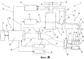
фиг. 2 - блок-схема сварочного аппарата со сварочной горелкой в упрощенном схематическом изображении.Figure 1 schematically shows the design of the welding machine;
FIG. 2 is a block diagram of a welding machine with a welding torch in a simplified schematic image.
В качестве вступления следует сказать, что в описанном примере выполнения одинаковые детали обозначены одинаковыми ссылочными позициями, причем подробное описание отдельных элементов может относится к аналогичным деталям с одинаковыми ссылочными позициями. Выбранные в описании указания на положение, например, вверху, внизу, сбоку и т.д. относятся к непосредственно описанным, а также изображенным фигурам и их следует по смыслу переносить на новое положение. Кроме того, отдельные признаки из показанного примера также могут представлять собой самостоятельные технические решения на уровне изобретения. As an introduction, it should be said that in the described embodiment, the same parts are denoted by the same reference numerals, moreover, a detailed description of the individual elements may relate to similar parts with the same reference numerals. Indications of position selected in the description, for example, at the top, bottom, side, etc. relate to the directly described, as well as depicted figures and they should, in the sense, be transferred to a new position. In addition, individual features from the shown example may also constitute independent technical solutions at the level of the invention.
На фиг. 1 показан сварочный аппарат 1 для самых разных способов сварки, например для сварки плавящимся электродом в инертном газе и металлическим электродом в активном газе, или для сварки неплавящимся электродом в инертном газе. Сварочный аппарат 1 содержит источник тока 2 с силовым блоком 3, устройство 4 управления и переключающий элемент 5. Переключающий элемент 5 или устройство 4 управления соединен с распределительным клапаном 6, который установлен в питающей линии 7 для газа 8, в частности защитного газа, например СО2, гелия или аргона и т.п., между газовым баллоном 9 и сварочной горелкой 10.In FIG. 1 shows a welding machine 1 for a wide variety of welding methods, for example, for welding with a consumable electrode in an inert gas and a metal electrode in an active gas, or for welding with a non-consumable electrode in an inert gas. The welding apparatus 1 contains a
Кроме того, устройством 4 управления может также управляться механизм 11 подачи проволоки, используемый при сварке плавящимся электродом в инертном газе и металлическим электродом в активном газе, причем по питающей линии 12 сварочная проволока 13 подается с питающего барабана 14 на участок сварочной горелки 10. Ток для формирования электрической дуги 15 между сварочной проволокой 13 и деталью 16 подается по питающей линии 17 от силового блока 3 на сварочную горелку 10 и на сварочную проволоку 13. In addition, the control device 4 can also control the wire feed mechanism 11 used when welding with a consumable electrode in an inert gas and a metal electrode in active gas, moreover, along the supply line 12, the
Для охлаждения сварочной горелки 10 сварочная горелка 10 может быть соединена контуром 18 охлаждения с резервуаром воды 20 с промежуточной установкой реле расхода 19, в результате чего при включении сварочной горелки 10 контур 18 охлаждения запускается устройством 4 управления, тем самым осуществляется охлаждение сварочной горелки 10 и сварочной проволоки 13. To cool the
Кроме того, сварочный аппарат 1 имеет устройство ввода и/или устройство 21 индикации, в котором можно установить различные параметры режима сварки или режимы работы сварочного аппарата 1. При этом установленные в устройстве ввода и/или устройстве индикации 21 параметры режима сварки передаются в устройство 4 управления и затем от него управляются отдельные элементы сварочного аппарата 1. In addition, the welding machine 1 has an input device and / or an
Разумеется, можно не соединять сварочную горелку 10, как в показанном на чертеже примере выполнения, отдельными проводами с отдельными элементами, в частности со сварочным аппаратом 1 или с механизмом 11 подачи проволоки, а объединять эти отдельные провода в общую гибкую связку проводов и присоединять ее к сварочной горелке 10. Of course, it is possible not to connect the
Кроме того, сварочная горелка 10 имеет устройство 22 ввода, а также устройство 23 индикации. В устройстве 22 ввода и устройстве 23 индикации пользователь в процессе сварки может считывать установленные параметры режима сварки в устройстве 23 индикации и через устройство 22 ввода воздействовать на отдельные параметры режима сварки, установленные, например, с помощью отдельных клавишных переключателей и т.п., благодаря чему можно производить оптимальную подгонку процесса сварки сварочной горелкой 10. Разумеется, имеется возможность, чтобы пользователь во время процесса сварки мог изменять установленные параметры режима сварки с помощью устройства 22 ввода, так что в любое время можно осуществлять оптимальное согласование процесса сварки. In addition, the
На фиг.2 показана блок-схема сварочного аппарата 1 в упрощенном виде. Figure 2 shows a block diagram of a welding machine 1 in a simplified form.
Устройство 4 управления образовано предпочтительно микропроцессорной системой управления 24. К одному вводу устройства 4 управления в частности, микропроцессорной системы управления 24, несколькими проводами 25, 26, из которых для наглядности изображено только по одному проводу 25, 26, присоединено устройство ввода и/или устройство 21 индикации. Но при этом возможно также, чтобы устройство ввода и/или устройство 21 индикации было разделено, то есть состояло из устройства ввода 27 и устройства 28 индикации. Кроме того, возможно, чтобы для устройства 27 ввода применялась клавиатура или любой другой возможный вид ввода, например, потенциометр, контактный экран или обычные клавишные переключатели и т.д. С помощью отдельных элементов устройства 27 ввода пользователь может набирать отдельные параметры режима сварки и соответствующими клавишами устанавливать их на сварочном аппарате 1, так что можно устанавливать и осуществлять соответствующий процесс сварки с необходимыми параметрами режима сварки для разных процессов сварки. The control device 4 is preferably formed by a
Устройство 28 индикации может быть реализовано, например, устройством индикации на экране дисплея, устройством индикации на светодиодах, устройством индикации на жидких кристаллах, устройством цифровой индикации, с помощью экрана или контактного экрана, причем на устройстве 28 индикации для пользователя отображаются выбранные параметры сварки, в частности их значения. Обмен данными между устройством ввода и/или устройством 21 индикации, в частности устройством 27 ввода и устройством 28 индикации, осуществляется по проводам 25, 26, то есть при приведении в действие устройства 27 ввода соответствующий сигнал передается в устройство 4 управления, после чего устройство 4 управления, в частности микропроцессорная система 24 управления, осуществляет соответствующий процесс управления. Одновременно или вслед за этим устройство управления 4 по проводу 26 приводит в действие устройство 28 индикации, после чего на устройстве 28 индикации появляется соответствующее значение или переданный из устройства 4 управления сигнал. The
К другим вводам и/или выводам микропроцессорной системы 24 управления по системе 29 шин, образованной, например, адресной шиной или шиной данных, присоединено запоминающее устройство 30. В запоминающем устройстве 30 хранятся отдельные данные и программы, в частности программы пользователя, необходимые для установки сварочного аппарата 1. Кроме того, в запоминающем устройстве 30 можно хранить другие данные пользователя. Для этого пользователь через устройство ввода 27 путем приведения в действие соответствующего органа может выдать команду на хранение в запоминающем устройстве 30 установленных параметров сварки сварочного аппарата 1 таким образом, что возможно повторное обращение к этим данным и к уставкам сварочного аппарата 1. To other inputs and / or outputs of the
Для управления соответствующим процессом сварки устройство 4 управления соединено, по меньшей мере, одним проводом 31 с силовым блоком 3, причем по проводу 31 осуществляется обмен данными между силовым блоком 3 и устройством управления 4. Кроме того, можно применить несколько проводов 31, причем на чертеже ради наглядности изображения показан только один провод 31. Силовой блок 3 может быть образован, например, инверторным источником тока 32 с первичным тактом. Для того, чтобы подавать в силовой блок 3 ток и напряжение, силовой блок 3 соединен питающими линиями 33, 34 с питающей сетью 35. Разумеется, возможно, чтобы вместо питающей сети 35 был использован любой другой вид энергии, например батарея, для питания силового блока 3. Питающая сеть 35 может быть также образована двухфазной сетью или трехфазной сетью. To control the corresponding welding process, the control device 4 is connected by at least one
Силовой блок 3 предназначен для преобразования энергии, подаваемой питающей сетью 35, в соответствующую энергию сварки, как это уже известно из уровня техники, и поэтому функция преобразования переданной энергии детально не рассматривается. Для создания сварочной горелкой 10 цепи сварочного тока, силовой блок 3 питающей линией 17 соединяют со сварочной горелкой 10, в то время как деталь 16 другой питающей линией 36 также соединена с силовым блоком 3, так что цепь тока может быть образована через сварочную горелку 10, в частности сварочную проволоку 13 и деталь 16. The
Для зажигания электрической дуги 15 между сварочной проволокой 13 и деталью 16 можно, например, установить в сварочном аппарате 1 генератор 37 высоких частот. Он соединен проводами 38, 39 как с устройством 4 управления, так и с питающей линией 17 для сварочной горелки 10. Разумеется, для зажигания электрической дуги 15 можно применять любой другой способ, входящий в уровень техники. Для зажигания электрической дуги между сварочной проволокой 13 и деталью 16 от генератора 37 высоких частот из устройства 4 управления при приведении в действие процесса сварки передается высокочастотный сигнал, который после этого модулируется по энергии сварки и тем самым осуществляется зажигание электрической дуги 15. For ignition of the
Для обеспечения возможности контроля за процессом сварки, в питающей линии 17 установлено измерительное устройство 40. При этом измерительное устройство 40 может быть образовано относящимся к уровню техники шунтом 41, вследствие чего электрический ток в питающей линии 17 может измеряться измерительным устройством 40. С этой целью с обеих сторон шунта 41 провода 42, 43 соединены с питающей линией 17. Затем провода 42, 43 соединены с преобразователем 44. Преобразователь 44 преобразует измеренный аналоговый сигнал в цифровой сигнал и затем по проводам 45 передает его в устройство 4 управления. Разумеется, можно выполнить преобразователь 44 как усилитель измеренного сигнала, так что измеренный сигнал не преобразуется, как было упомянуто, в цифровой сигнал, а измеренный сигнал усиливается на заранее устанавливаемое значение. To enable monitoring of the welding process, a measuring
Для того, чтобы иметь возможность измерения также и напряжения на сварочной горелке 10 между сварочной проволокой 13 и деталью 16, другой провод 46 соединен с преобразователем 44 и питающей линией 36. Преобразователь 44 предназначен для преобразования измеренных измерительным устройством 40 аналоговых значений или сигналов между сварочной проволокой 13 и деталью 16 в цифровые значения или сигналы и усиления аналоговых сигналов последующей передачи в устройство 4 управления, так что устройство 4 управления может произвести обработку принятых значений или сигналов. In order to be able to measure the voltage on the
Далее устройство 4 управления имеет шину 47 данных или шину массива данных. Устройство управления соединено с последовательной шиной 47 данных в частности, шиной массива данных, к которой могут быть присоединены сварочная горелка 10 и/или другие элементы сварочного аппарата 1 и/или сварочной установки, например сварочный робот, сварочный автомат, технологическое оборудование, автоматическая линия, поворотный стол и т.д. Шина 47 данных может быть образована, например, контроллером Area Network, интершиной S по стандарту DIN E19258/EN50170 и т.д. и может иметь последовательный интефейс, в частности последовательные порты RS 232 и RS 458. Шина 47 данных получена системой шин 48 между устройством 4 управления сварочной горелкой 10, которая состоит, по меньшей мере, из двух электрических проводов. К системе 48 шин присоединены, по меньшей мере, два ответвителя устройства, состоящие из отдельных деталей для передачи данных по шине 47 данных и вследствие этого обозначаемые как задающие устройства 49, 50, и тем самым устройство ввода 22 и устройство индикации 23 соединены с устройством 4 управления. С этой целью сварочная горелка 10, как это схематически показано штриховыми линиями, имеет отдельные конструктивные элементы для передачи данных по системе 48 шин. Further, the control device 4 has a
Благодаря выполнению шины 47 данных в виде известной из уровня техники шины данных, например, RS 232, для обмена данных с устройством 4 управлениям в горелке 10 установлено другое задающее устройство 50 интерфейса с надлежащими функциональными модулями, как это показано схематически. В сварочной горелке 10 имеется возможность установить через аналоговые и/или цифровые вводы и/или выводы 51 соответствующие органы 52 управления, в частности отдельные клавишные переключатели 53-56. Отдельные необходимые для передачи данных по шине данных 47 конструктивные элементы, например задающее устройство индикации, аналоговые и/или цифровые вводы и/или выводы 51, задающее устройство 50 интерфейса и т.д., установлены в сварочной горелке 10. Due to the implementation of the
Далее к задающему устройству 50 интерфейса можно присоединить устройство 23 индикации, так что передача данных о режиме индикации может осуществляться также через задающее устройство 50 интерфейса. Further, an
Благодаря установке отдельных органов 52 управления для устройства 22 ввода создается возможность, чтобы пользователь через сварочную горелку 10 мог вызвать и установить различные последовательности операций или параметры режима сварки, которые снова выводятся на устройство 23 индикации на горелке 10, то есть, например, в результате нажатия клавишного переключателя 53-56 из задающего устройства 50 интерфейса по системе 48 шин в устройство 4 управления передается сигнал, после чего устройство 4 управления осуществляет соответствующее изменение режима работы и это изменение затем передается через задающее устройство 49 интерфейса в систему 48 шин, после чего задающее устройство 50 интерфейса выдает соответствующий запускающий сигнал для устройства 23 индикации и тем самым пользователь может считать произведенное в устройстве индикации 23 изменение. Owing to the installation of
За счет соединения сварочной горелки 10, в частности, ее устройства 22 ввода и устройства 23 индикации с устройством 4 управления по шине 47 данных по причине последовательной передачи данных возможна экономия проводов для связи между сварочной горелкой 10 и устройством управления 4, так как для последовательной передачи данных требуется лишь незначительное количество проводов, например 2-9 проводов. Передача данных по последовательной шине 47 данных осуществляется соответствующим протоколом передачи, причем может применяться любой известный из уровня техники протокол передачи. By connecting the
За счет установки активных и пассивных конструктивных элементов для передачи данных в сварочной горелке 10 с преимуществом достигается то, что можно применять многообразие разных типов сварочных горелок 10 для одного и того же сварочного аппарата 1, то есть, например, сварочная горелка 10 с соответствующим задающим устройством 50, например RS 232, может применяться уже не с четырьмя клавишными переключателями 53-56, как в изображенном примере выполнения, а с более чем четырьмя клавишными переключателями 53-56, так что специальные функции могут выполняться также сварочной горелкой 10, причем для подобной сварочной горелки 10 более не требуются дополнительные провода или управляющие линии. Это возможно постольку, поскольку при приведении в действие установленных дополнительных клавишных переключателей 53-56 передача выполняемых функций или изменений осуществляется по последовательной шине данных 47 с помощью одного и того же протокола передачи, так что можно применять любое количество клавишных переключателей 53-56. Обработка переданных данных производится затем в устройстве 4 управления так, что в соответствии с переданными данными устройство 4 управления может осуществлять соответствующие процессы управления и регулирования. By installing active and passive structural elements for transmitting data in the
Для этого уже не требуется, чтобы сварочный аппарат 1 был согласован с разными сварочными горелками 10, а скорее программное обеспечение или программы, заложенные в запоминающем устройстве 30, должны быть согласованы с отдельными сварочными горелками 10, так как самые разные сварочные горелки 10 осуществляют передачу данных со стандартным протоколом передачи. Кроме того, также, например, возможно, чтобы при покупке новой сварочной горелки 10 пользователь получил соответствующую дискету с программой обработки, с помощью которой он может путем установки в дисковод, встроенный в сварочный аппарат 1 или соединенный со сварочным аппаратом 1, и путем передачи данных по шине 47 данных за счет соединения шины 47 данных с компьютером произвести согласование программного обеспечения, введенного в запоминающее устройство 30, так что затем пользователь может в любое время использовать соответствующую сварочную горелку 10. Возможно также согласовать программы или программное обеспечение сварочного аппарата 1 с самыми разными сварочными горелками 10, так что пользователь должен только соединить сварочную горелку 10 с гибкой трубкой или со сварочным аппаратом 1, после чего пользователь может полностью использовать функции сварочного аппарата 10 для процесса сварки. For this, it is no longer necessary that the welding machine 1 be matched with different welding torches 10, but rather the software or programs stored in the
Разумеется, путем установки перезаписываемого или изменяемого запоминающего устройства 30 в устройстве 4 управления можно вводить программное обеспечение, в частности программы пользователя, в запоминающее устройство 30 так, чтобы иметь доступ к программному обеспечению через интерфейс, в частности шину 47 данных, и тем самым в любое время осуществлять изменение программного обеспечения. Of course, by installing a rewritable or
За счет такого выполнения с преимуществом достигается то, что для одного и того же сварочного аппарата 1 можно применять любое количество сварочных горелок 10, благодаря чему создается относительно высокая гибкость для пользователя. Кроме того, также можно проводить при смене сварочной горелки 10 автоматическое опознавание. Due to this embodiment, it is advantageously achieved that any number of welding torches 10 can be used for the same welding machine 1, thereby creating relatively high flexibility for the user. In addition, it is also possible to carry out automatic recognition when changing the
Это можно осуществить, например, таким образом, чтобы в сварочной горелке 10 в запоминающее устройство был введен код опознавания, который при приведении в действие сварочной горелки 10 или при пуске сварочного аппарата 1 автоматически передается от задающего устройства 50 интерфейса в шину 47 данных так, что этот код опознавания передается в устройство 4 управления. После этого устройство 4 управлениями производит сравнение переданного от сварочной горелки 10 кода опознавания с введенными в запоминающем устройстве 30 кодами опознавания таким образом, что при совпадении устройство 4 управления сможет считать дополнительные данные по этому коду из запоминающего устройства и тем самым опознать тип сварочной горелки 10. This can be done, for example, in such a way that an identification code is entered into the memory in the
Кроме того, также возможно, чтобы в соответствии с присоединенной к сварочному аппарату 1 сварочной горелкой 10 устройство 4 управления осуществляло согласование операционной системы и согласование программ пользователя, то есть, чтобы устройство 4 управления осуществляло начальные установки в разных параметрах режима сварки путем вывода из запоминающего устройства 30, благодаря чему достигается оптимизация процесса сварки. Кроме того, можно снабдить разные типы сварочных горелок 10 при необходимости разными устройствами 22 ввода и/или 23 индикации, причем для этого установлены самые разные сварочные горелки 10, например соединяемый с шиной 47 данных запоминающий элемент, для определения или ввода в память присвоенного типу сварочной горелки 10 кода опознавания, и тем самым может осуществляться автоматическое опознавание сварочной горелки 10. In addition, it is also possible that, in accordance with the
В изображенном примере выполнения, например, возможно, чтобы клавишный переключатель 53 был ответственным за увеличение значения, показываемого на устройстве 23 индикации, в частности устройства индикации на жидких кристаллах, в то время как клавишный переключатель 54 используется для уменьшения этого значения, то есть пользователь при нажатии клавишного переключателя 53 может увеличить показываемое значение, например, с 50 до 60. Это может осуществляться, например, пошаговым переключением клавишного переключателя 53, за счет чего запускается передача данных через задающее устройство 50 интерфейса в устройство 4 управления, после чего устройство 4 управления по проводу 38 соответственно запускает силовой блок 3. In the illustrated embodiment, for example, it is possible for the
Другие клавишные переключатели 55, 56 могут применяться, например, для выборки разных параметров режима сварки, то есть, например, при использовании клавишного переключателя 55 устройства 23 индикации переходит от параметра режима работы величины тока на диаметр сварочной проволоки и т.д., так что установленный или заданный диаметр сварочной проволоки показывается на устройстве 23 индикации. Путем нажатия на клавишный переключатель 55 пользователь может считать отдельные параметры режима сварки. Кроме того, например, можно использовать клавишные переключатели 55 и 56 для разных направлений прокрутки отдельных параметров режима сварки. За счет такой сварочной горелки 10 пользователь имеет возможность выбирать и устанавливать все имеющиеся в распоряжении параметры режима сварки со сварочной горелки 10. Other
Отличие от известных из уровня техники сварочных горелок 10 с установленными в сварочной горелке 10 устройством 22 ввода и устройством 23 индикации заключается в том, что отдельные органы 52 управления в относящейся к уровню техники сварочной горелке 10 присоединены отдельными проводами непосредственно к устройству 4 управления, в частности к микропроцессорному устройству 24 управления, то есть, например, при использовании относящейся к уровню техники сварочной горелки 10 с клавишей горелки, клавишей вверх-вниз, потенциометром, устройством индикации на светодиодах или устройством 7-сегментной индикации, эти органы 52 управления присоединены отдельными проводами непосредственно к микропроцессорному устройству 24 управления. Отдельными прямыми соединениями отдельных органов 52 управления с устройством 4 управления большое количество проводов проведено через гибкую связку проводов к сварочному аппарату 1 так, что создается гибкая связка проводов соответственно большой толщины и тем самым гибкость сварочной горелки 10 ограничивается. Существенный недостаток относящейся к уровню техники сварочной горелки 10 заключается в том, что при применении разных сварочных горелок 10 в зависимости от объема функций отдельных сварочных горелок 10 сварочный аппарат 1, в частности источник 2 тока, также необходимо выполнять по-разному или с слишком большими размерами для того, чтобы к сварочному аппарату 1 можно было присоединять большое количество разных сварочных горелок 10. The difference from the prior art welding torches 10 with an
Кроме того, в относящихся к уровню техники системах, в которых органы 52 управления соединены непосредственно с устройством 4 управления, это представляет собой случай, когда при изменении функции сварочной горелки 10 необходимо также произвести изменение в сварочном аппарате 1, в частности в электронном устройстве, вследствие чего возникают высокие затраты на применение новой модели сварочной горелки 10. Для обеспечения соответствующей помехозащищенности отдельные конструктивные элементы задающего устройства для подавления помех в проводах необходимо присоединять непосредственно к отдельным органам управления 52 или к устройству индикации 23. По причине большого количества проводов для отдельных органов 52 управления необходимы большие затраты для подавления помех в проводах, так что возникает увеличение габаритов сварочной горелки 10 и тем самым ограничение гибкости сварочной горелки 10. In addition, in the prior art systems in which the
Так как за счет разной конструкции разных сварочных горелок 10 также возможно, что в примененных по уровню техники сварочных горелках 10 могут быть осуществлены разные разводки контактов и кабелей, для разных сварочных горелок 10 должны быть выполнены соответствующие аппаратные средства сварочного аппарата 1 так, что затраты для такого сварочного аппарата 1 значительно увеличиваются. Вследствие выполнения относящейся к уровню техники сварочной горелки 10 с отдельными, соединенными непосредственно с устройством 4 управления проводами также создается ограничение функциональности сварочных горелок 10, так как для требующего меньших затрат на изготовление сварочного аппарата 1 он не может работать с любой сварочной горелкой 10, так как в противном случае для самых разных сварочных горелок 10 с самыми разными присоединениями и вариантами органов 52 управления необходимо соответствующее выполнение аппаратных средств в сварочном аппарате, вследствие чего значительно повышаются затраты, то есть, например, при применении сварочной горелки 10 только с двумя клавишными переключателями 53, 54 создается другое управление аппаратными средствами по сравнению с применением сварочной горелки 10 с четырьмя или более клавишными переключателями 53-56, так как при применении сварочной горелки 10 только с двумя клавишными переключателями 53, 56 проведены, по меньшей мере, два или три провода для устройства 4 управления, в то время как при применении сварочной горелки с четырьмя клавишными переключателями 53-56 проводятся, по меньшей мере, четыре или пять проводов к устройству 4 управления, и тем самым аппаратные средства сварочного аппарата 1 должны быть согласованы с разными типами сварочной горелки 10. Since, due to the different design of different welding torches 10, it is also possible that different pin and cable routings can be implemented in the welding torches 10 used according to the prior art, the corresponding hardware of the welding machine 1 must be made for different welding torches 10 so that the costs for such a welding machine 1 is significantly increased. Due to the implementation of the prior
За счет выполнения сварочной горелки 10 с шиной 47 данных достигается то, что в результате стандартизации интерфейсов, а также протокола передачи для обмена данными между сварочным аппаратом 1 и сварочной горелкой 10 можно применять для самых разных сварочных горелок 10 стандартные разводки контактов горелки, так что при разном конструктивном исполнении сварочных горелок 10 разводка контактов горелки может сохраняться одинаковой и соответственно количество проводов между сварочным аппаратом 1 и сварочной горелкой 10 не должно увеличиваться вследствие разных функций сварочной горелки 10 по причине последовательной передачи данных. За счет выполнения сварочной горелки 10 и соединения сварочной горелки 10 со сварочным аппаратом 1 через шину 45 данных согласно изобретению достигается то, что дистанционная установка с помощью дистанционного регулятора, известного из уровня техники для изменения параметра режима сварки, может быть ненужной, так как сварочная горелка может быть выполнена с самыми разными функциями и тем самым применение дистанционного задающего устройства или дистанционного регулятора более не требуется. За счет применения небольшого количества проводов, в частности двух-девяти проводов, для передачи данных с преимуществом достигается то, что гибкая связка проводов для соединения сварочной горелки 10 со сварочным аппаратом 1 может быть выполнена очень небольшой толщины, так что создается высокая гибкость для пользователя и тем самым также возможность надежной передачи данных на большие расстояния, как это имеет место, например, при применении сварочного аппарата 1 на судостроительных заводах. By performing the
В новой модели сварочной горелки 10 с другими разными функциями и специальными функциями отсутствует необходимость изменения аппаратных средств в сварочном аппарате 1, так как благодаря стандартной шине 47 данных передача данных осуществляется последовательно таким образом, что в сварочной горелке 10 можно установить любое количество органов управления 52 и соответственно любое количество устройств 23 индикации, то есть вследствие последовательной передачи данных отдельные проведенные в сварочной горелке 10 процессы управления преобразуются задающим устройством 50 интерфейса в последовательный сигнал данных или в протокол передачи и он передается по системе 48 шин в устройство 4 управления, вследствие чего в новой модели сварочной горелки 10 также за счет применения стандартной шины 47 данных может применяться стандартная разводка контактов горелки и тем самым отпадает необходимость в изменении аппаратных средств. In the new model of the
Следующее преимущество выполнения сварочного аппарата 1 и сварочной горелки 10 согласно изобретению заключается в том, что отдельные активные конструктивные элементы можно установить в сварочной горелке 10, так как для последовательной передачи данных необходимо только небольшое количество проводов и тем самым принятые в системе 48 шин помехи могут отфильтровываться непосредственно в сварочной горелке 10, так что возможна передача данных по системе 48 шин без помех. Разумеется, можно осуществлять фильтрацию помех с помощью соответствующего программного обеспечения или в соответствии с программным обеспечением. A further advantage of the embodiment of the welding machine 1 and the
Можно также осуществлять различные варианты сварочных горелок 10, так как передача данных по системе 48 шин стандартная, поэтому для нового варианта сварочной горелки 10 необходимо согласовывать только операционную систему или программное обеспечение сварочного аппарата 1 и тем самым изменение аппаратных средств в сварочном аппарате 1 уже не требуется. Благодаря такому выполнению пользователь имеет значительную экономию затрат, так что пользователь при применении сварочных горелок 10 нового типа может соединять их снова с прежним сварочным аппаратом 1, используя шину 47 данных, и тем самым не несет расходов по изменению конструктивных элементов в сварочном аппарате 1. Благодаря последовательной передаче данных достигается также экономия отдельных проводов цепи управления в системе 48 шин, так как вследствие стандартной передачи данных, в частности последовательной передачи данных, требуется лишь небольшое количество проводов. It is also possible to carry out various versions of welding torches 10, since the data transfer through the 48 bus system is standard; therefore, for the new version of
Достигается также экономия затрат при разработке сварочных горелок 10, так как благодаря соединению активных и пассивных конструктивных элементов для передачи данных на участке сварочной горелки 10 можно стандартизировать компоновку схем и тем самым использовать для разных сварочных горелок 10 одну и ту же конструкцию с разными функциями. Cost savings are also achieved in the development of welding torches 10, since by connecting active and passive structural elements for transmitting data on the site of the
Кроме того, благодаря применению шин 47 данных в сварочном аппарате 1 имеется возможность управления внешними элементами по шине данных, то есть, например, при установке сварочного аппарата 1 в сварочный робот или сварочный автомат - сварочный аппарат 1, в частности, устройство 4 управления можно соединять со сварочным роботом или сварочным автоматом, в частности, с его системой управления, по шине данных создается возможность обмена данными между сварочным аппаратом 1 и сварочным роботом или сварочным автоматом. Кроме того, можно, например, при применении сварочного аппарата 1 в автоматической линии или в технологическом оборудовании для автомобильной промышленности осуществлять управление подачей отдельных деталей с использованием сварочного аппарата 1, то есть, например, по окончании процесса сварки сварочный аппарат 1 передает по 47 шине данных сигнал на автоматическую линию или технологическое оборудование, в частности, в устройство управления или устройство программного управления от ЗУ или устройство управления с помощью компьютера, примененное для автоматической линии или технологического оборудования, так что устройство управления может опознавать, что процесс сварки сварочным аппаратом закончен и тем самым включается дальнейшая подача только что обработанной детали. In addition, due to the use of
Можно также посредством установки внешнего интерфейса применять его для соединения сварочного аппарата 1 с компьютером, так что через шину 47 данных можно осуществлять изменения программного обеспечения. Кроме того, посредством установки устройства 4 управления и стандартной шины 47 данных в сварочном аппарате 1 при работе сварочного аппарата в монтажном цехе для установки других элементов, например поворотного стола и т.д., можно управлять устройством 4 управления сварочного аппарата 1, так что дополнительные устройства управления для других элементов не требуются. You can also, by installing an external interface, use it to connect the welding machine 1 to a computer, so that software changes can be made via
За счет применения шины 47 данных далее достигается то, что необходимые для сварочного аппарата 1 другие элементы, например механизм 11 подачи проволоки и т.д., могут управляться также через шину 47 данных или систему 48. Это показано, например, на фиг.2 в виде следующего установленного в шине данных задающего устройства 57, то есть за счет соединения механизма 11 подачи проволоки с задающим устройством 57 интерфейса может осуществляться последовательный обмен данными между устройством 4 управления и механизмом 11 подачи проволоки. Преимущество заключается в том, что механизм 11 подачи проволоки соединен с устройством 4 управления не непосредственно отдельными проводами, как это известно из уровня техники, а управление осуществляется также с использованием стандартной шины 47 данных, вследствие чего обеспечивается экономия проводов и надежная передача данных. Тем самым создается возможность применения разных механизмов подачи проволоки, так как вследствие применения шины 47 данных необходимо осуществить только одно изменение программного обеспечения в устройстве 4 управления для согласования с механизмом 11 подачи проволоки. By using the
Разумеется, в шине 47 данных, в частности в системе 48 шин, можно установить несколько других задающих устройств 57 интерфейса, благодаря чему устройством 4 управления по шине 47 данных можно управлять любым количеством элементов. Of course, in the
Разумеется, вместо электрической шины данных можно применять любую другую известную из уровня техники систему передачи, то есть, например, можно вместо электрических проводов применять один или несколько световодов, по которым осуществляется обмен данными, вследствие чего создается соответственно высокая помехозащищенность, так как электрические воздействия при передаче данных по световоду можно уже не учитывать. При таком выполнении шины 47 данных по световоду необходимо согласовывать отдельные задающие устройства 49, 50 и 57 с соответствующей системой управления. Of course, instead of an electrical data bus, any other transmission system known from the prior art can be used, that is, for example, instead of electrical wires, one or more optical fibers can be used through which data is exchanged, which results in correspondingly high noise immunity, since electrical influences Data transmission through the fiber can no longer be taken into account. With this embodiment of the
Кроме того, разные типы сварочных горелок 10 при необходимости можно снабдить разными устройствами 22 ввода и/или 23 индикации, причем ответвители соответственно одинакового типа, в частности задающие устройства 49, 50, 57 интерфейса, установлены для присоединения к шине данных 47, вследствие чего можно применять большое количество выполненных по-разному сварочных горелок 10. In addition, different types of welding torches 10, if necessary, can be equipped with different input devices and / or
Кроме того, можно соединить шину 47 данных с внешним устройством управления. Для этого устройство управления имеет устройство 22 ввода и/или устройство 23 индикации, так что управление сварочным аппаратом 1, в частности установка отдельных параметров режима сварки, может осуществляться через орган управления. При этом орган управления может независимо от гибкой связки проводов своей собственной связкой проводов соединяться со сварочным аппаратом 1, в частности с шиной 47 данных. Кроме того, можно выполнить устройство управления таким образом, чтобы оно, например, было соединено фиксатором или другим крепежным средством со сварочной горелкой 10. Для этого также можно, как это также имеет место для ранее описанных вариантов выполнения, соединить устройство 22 ввода и/или устройство 23 индикации во время процесса сварки с устройством 4 управления для передачи управляющего сигнала по шине 47 данных, так что во время процесса сварки возможно изменение параметров режима сварки и тем самым пользователь может осуществлять оптимальное согласование процесса сварки. In addition, it is possible to connect the
Разумеется, передачу данных можно осуществлять без проводов, по меньшей мере, на некоторых участках сварочного аппарата 1 с элементами сварочного аппарата 1, в частности сварочной горелкой 10, или внешними элементами, например световыми сигналами, например инфракрасными сигналами. При этом для беспроводной передачи данных снова используется стандартный или унифицированный протокол передачи отдельных элементов, так что у пользователя имеется в распоряжении высокая гибкость при работе с таким сварочным аппаратом 1. Кроме того, можно также, например, при применении нескольких сварочных аппаратов 1 присвоить каждому сварочному аппарату 1 код опознавания, с помощью которого задается распределение данных. Этот код опознавания каждого элемента сварочного аппарата введен, например, в энергонезависимое ЗУ, благодаря чему каждый элемент при приеме данных отфильтровывает сначала данный код и затем при совпадении может произвести или выполнить соответствующий процесс управления. Of course, data transmission can be carried out wirelessly, at least in some areas of the welding machine 1 with elements of the welding machine 1, in particular a
Кроме того, сварочная горелка 10 дополнительно к шине 47 данных может иметь органы 52 управления, соединенные непосредственно с устройством 4 управления, в частности микропроцессорной системой 24 управления, которая соединена проводами непосредственно с устройством 4 управления, то есть, чтобы осуществлялся параллельный режим работы между устройством 22 ввода и органами 52 управления, соединенными непосредственно с устройством 4 управления. При этом имеет преимущество то, что при отказе шины 47 данных основные функции сварочной горелки 10 сохраняются, так что пользователь может в любое время проводить процесс сварки. Кроме того, пользователь может изменять параметры режима сварки с помощью устройства 21 ввода и/или индикации на сварочном аппарате 1. При таком выполнении сварочная горелка 10 соединена непосредственно с устройством 4 управления в основном теми органами 52 управления, например, переключателем для пуска процесса сварки, которые обязательно необходимы для процесса сварки, так как изменение параметров режима сварки в любое время может производиться пользователем на сварочном аппарате 1. In addition, the
В заключение следует указать на то, что в вышеописанном примере выполнения отдельные детали показаны непропорционально увеличенными или схематично для того, чтобы облегчить понимание решения согласно изобретению. Кроме того, отдельные части вышеописанной комбинации признаков примера выполнения в сочетании с другими отдельными признаками могут составлять самостоятельные технические решения на уровне изобретения. In conclusion, it should be pointed out that in the above embodiment, individual parts are shown disproportionately enlarged or schematically in order to facilitate understanding of the solution according to the invention. In addition, individual parts of the above combination of features of an exemplary embodiment in combination with other individual features may constitute independent technical solutions at the level of the invention.
Прежде всего отдельные, показанные на фиг.1, 2 примеры выполнения, могут составлять самостоятельные технические решения на уровне изобретения. Относящиеся к этому задачи и решения в соответствии с изобретением представлены в детальных описаниях этих фигур. First of all, the individual examples shown in FIGS. 1 and 2 may constitute independent technical solutions at the level of the invention. Related tasks and solutions in accordance with the invention are presented in detailed descriptions of these figures.
Перечень позиций на чертежах
1. Сварочный аппарат
2. Источник тока
3. Силовой блок
4. Устройство управления
5. Переключающий элемент
6. Распределительный клапан
7. Питающая линия
8. Газ
9. Ресивер газа
10. Сварочная горелка
11. Механизм подачи проволоки
12. Питающая линия
13. Сварочная проволока
14. Питающий барабан
15. Электрическая дуга
16. Деталь
17. Питающая линия
18. Контур охлаждения
19. Реле расхода
20. Резервуар воды
21. Устройство ввода и/или индикации
22. Устройство ввода
23. Устройство индикации
24. Микропроцессорная система управления
25. Провод
26. Провод
27. Устройство ввода
28. Устройство индикации
29. Система шин
30. Запоминающее устройство
31. Провод
32. Инверторный источник тока
33. Питающая линия
34. Питающая линия
35. Питающая сеть
36. Питающая линия
37. Генератор высоких частот
38. Провод
39. Провод
40. Измерительное устройство
41. Шунт
42. Провод
43. Провод
44. Преобразователь
45. Провод
46. Провод
47. Шина данных
48. Система шин
49. Задающее устройство интерфейса
50. Задающее устройство интерфейса
51. Ввод и/или вывод
52. Орган управления
53. Клавишный переключатель
54. Клавишный переключатель
55. Клавишный переключатель
56. Клавишный переключатель
57. Задающее устройство интерфейсазThe list of items in the drawings
1. Welding machine
2. Current source
3. Power block
4. The control device
5. The switching element
6. Distribution valve
7. Supply line
8. Gas
9. Gas receiver
10. Welding torch
11. Wire feed mechanism
12. Supply line
13. Welding wire
14. Feeding drum
15. Electric arc
16. Detail
17. Supply line
18. Cooling circuit
19. Flow switch
20. Water tank
21. Input and / or indication device
22. Input device
23. Indication device
24. Microprocessor control system
25. Wire
26. Wire
27. Input device
28. Indication device
29. Tire system
30. Storage device
31. Wire
32. Inverter current source
33. Supply line
34. Supply line
35. Power supply
36. Supply line
37. High frequency generator
38. Wire
39. Wire
40. Measuring device
41. Shunt
42. Wire
43. Wire
44. Converter
45. Wire
46. Wire
47. Data bus
48. Tire system
49. The driver of the interface
50. The driver of the interface
51. Input and / or output
52. Governing body
53. Key switch
54. Key switch
55. Key switch
56. Key switch
57. Interface driver
Claims (22)
Applications Claiming Priority (2)
| Application Number | Priority Date | Filing Date | Title |
|---|---|---|---|
| ATA34/98 | 1998-01-13 | ||
| AT0003498A AT411880B (en) | 1998-01-13 | 1998-01-13 | CONTROL DEVICE FOR A WELDING MACHINE |
Publications (2)
| Publication Number | Publication Date |
|---|---|
| RU2000121052A RU2000121052A (en) | 2002-08-27 |
| RU2218251C2 true RU2218251C2 (en) | 2003-12-10 |
Family
ID=3479786
Family Applications (1)
| Application Number | Title | Priority Date | Filing Date |
|---|---|---|---|
| RU2000121052/02A RU2218251C2 (en) | 1998-01-13 | 1999-01-08 | Control unit for welding apparatus |
Country Status (14)
| Country | Link |
|---|---|
| US (1) | US6315186B1 (en) |
| EP (1) | EP1047521B9 (en) |
| JP (2) | JP5203546B2 (en) |
| CN (1) | CN1253281C (en) |
| AT (1) | AT411880B (en) |
| AU (1) | AU743838B2 (en) |
| BR (1) | BR9906913B1 (en) |
| DE (1) | DE59905553D1 (en) |
| DK (1) | DK1047521T4 (en) |
| ES (1) | ES2199539T4 (en) |
| NO (1) | NO324385B1 (en) |
| PL (1) | PL188266B1 (en) |
| RU (1) | RU2218251C2 (en) |
| WO (1) | WO1999036219A1 (en) |
Cited By (9)
| Publication number | Priority date | Publication date | Assignee | Title |
|---|---|---|---|---|
| RU2545869C2 (en) * | 2009-06-10 | 2015-04-10 | Сименс Акциенгезелльшафт | Welding of shafts for vertical axis of rotation |
| RU2548545C2 (en) * | 2009-06-12 | 2015-04-20 | Кемппи Ой | Device for optimisation of welding |
| RU2555308C2 (en) * | 2010-07-14 | 2015-07-10 | Иллинойс Тул Воркс Инк. | Control over heat feed for welding systems |
| RU2695694C2 (en) * | 2014-08-29 | 2019-07-25 | СиАрСи-ЭВАНС ПАЙПЛАЙН ИНТЕРНЭШНЛ ИНК. | Welding method and system |
| US10480862B2 (en) | 2013-05-23 | 2019-11-19 | Crc-Evans Pipeline International, Inc. | Systems and methods for use in welding pipe segments of a pipeline |
| US10589371B2 (en) | 2013-05-23 | 2020-03-17 | Crc-Evans Pipeline International, Inc. | Rotating welding system and methods |
| US10695876B2 (en) | 2013-05-23 | 2020-06-30 | Crc-Evans Pipeline International, Inc. | Self-powered welding systems and methods |
| US11458571B2 (en) | 2016-07-01 | 2022-10-04 | Crc-Evans Pipeline International, Inc. | Systems and methods for use in welding pipe segments of a pipeline |
| US11767934B2 (en) | 2013-05-23 | 2023-09-26 | Crc-Evans Pipeline International, Inc. | Internally welded pipes |
Families Citing this family (100)
| Publication number | Priority date | Publication date | Assignee | Title |
|---|---|---|---|---|
| AT412389B (en) * | 2000-12-11 | 2005-02-25 | Fronius Int Gmbh | SYSTEM FOR IMPLEMENTING A WELDING PROCESS |
| AT411973B (en) * | 2001-01-26 | 2004-08-26 | Fronius Schweissmasch Prod | METHOD FOR OPERATING A WELDING DEVICE OR A WELDING SYSTEM |
| JP2002321056A (en) * | 2001-04-25 | 2002-11-05 | Obara Corp | Welding control device |
| WO2003012766A1 (en) * | 2001-07-30 | 2003-02-13 | Sergiy Kishinsky | Device for dynamic displaying of information |
| AT413658B (en) * | 2001-09-12 | 2006-04-15 | Fronius Int Gmbh | REMOTE REGULATOR AND CONTROL UNIT FOR A WELDING DEVICE |
| DE10155000B4 (en) * | 2001-11-08 | 2008-04-30 | Lorch Schweißtechnik GmbH | Electrical control unit, in particular an electric welding power source, and system comprising such a control unit |
| AT502378B1 (en) * | 2002-04-11 | 2007-03-15 | Fronius Int Gmbh | PROCESS FOR PARAMETER SELECTION ON WELDING EQUIPMENT |
| US6590184B1 (en) * | 2002-05-15 | 2003-07-08 | Illinois Tool Works Inc. | Rack assembly support for welding machine |
| JP2005535456A (en) * | 2002-07-04 | 2005-11-24 | フロニウス・インテルナツィオナール・ゲゼルシャフト・ミット・ベシュレンクテル・ハフツング | Method of operating welding apparatus and welding apparatus |
| US6815640B1 (en) * | 2002-07-09 | 2004-11-09 | Lincoln Global, Inc. | Apparatus, system and method to facilitate reconfigurable welding power supply |
| CA2429974A1 (en) * | 2003-05-26 | 2004-11-26 | Jody Rice | Welding torch nozzle cleaning station |
| US8124913B2 (en) * | 2003-10-23 | 2012-02-28 | Fronius International Gmbh | Method for controlling and/or adjusting a welding process and welding device for carrying out a welding process |
| US7411154B2 (en) * | 2005-03-24 | 2008-08-12 | Illinois Tool Works Inc. | Control panel for a welding-type apparatus |
| AT502283B1 (en) * | 2005-07-15 | 2007-05-15 | Fronius Int Gmbh | WELDING PROCESS AND WELDING SYSTEM DETERMINING THE POSITION OF THE WELDING BURNER |
| JP5001536B2 (en) * | 2005-07-19 | 2012-08-15 | 株式会社ダイヘン | Arc welding torch |
| US10144080B2 (en) | 2005-08-25 | 2018-12-04 | Lincoln Global, Inc. | Torch for electric arc welding or plasma cutting system |
| US8431862B2 (en) * | 2005-08-25 | 2013-04-30 | Lincoln Global, Inc. | Torch for electric arc welding system |
| AT504197B1 (en) * | 2006-09-08 | 2010-01-15 | Fronius Int Gmbh | WELDING METHOD FOR CARRYING OUT A WELDING PROCESS |
| US7753740B2 (en) | 2007-07-20 | 2010-07-13 | Numatics, Incorporated | Modular electrical bus system |
| US20090212027A1 (en) * | 2008-02-21 | 2009-08-27 | Hypertherm, Inc. | Binary Signal Detection |
| US20090222804A1 (en) * | 2008-02-29 | 2009-09-03 | Illinois Tool Works, Inc. | Embedded firmware updating system and method |
| US9352411B2 (en) | 2008-05-28 | 2016-05-31 | Illinois Tool Works Inc. | Welding training system |
| US8803033B2 (en) | 2008-10-22 | 2014-08-12 | Lincoln Global, Inc. | Semi-automatic brazing device |
| US8592722B2 (en) * | 2008-11-03 | 2013-11-26 | Illinois Tool Works Inc. | Weld parameter interface |
| US20110180517A1 (en) * | 2010-01-26 | 2011-07-28 | Illinois Tool Works Inc. | Methods and systems for binding a wireless control device to a welding power source |
| US8592723B2 (en) * | 2010-02-12 | 2013-11-26 | Illinois Tool Works Inc. | Weld bank data structures for welding applications |
| US20110220616A1 (en) * | 2010-03-10 | 2011-09-15 | Illinois Tool Works Inc. | Welding device with integral user interface |
| CN102371414A (en) * | 2010-08-20 | 2012-03-14 | 中国海洋石油总公司 | Network-based pipeline all-position welding control system |
| DE102010042591B4 (en) | 2010-10-18 | 2012-08-30 | Lorch Schweißtechnik GmbH | Welding torch and arc welding machine with such a welding torch |
| JP5594118B2 (en) * | 2010-12-16 | 2014-09-24 | パナソニック株式会社 | Arc welding equipment, arc welding power supply and welding torch |
| AT510411B1 (en) * | 2011-04-12 | 2012-04-15 | Fronius International Gmbh | wire inlet |
| US9101994B2 (en) | 2011-08-10 | 2015-08-11 | Illinois Tool Works Inc. | System and device for welding training |
| DE202011110810U1 (en) | 2011-11-04 | 2016-07-14 | Ewm Ag | Control unit for a welding device |
| EP2589454B1 (en) | 2011-11-04 | 2016-03-30 | Ewm Ag | Control unit for a welding device, welding torch with an interface, and welding apparatus with such components |
| US20130112660A1 (en) * | 2011-11-08 | 2013-05-09 | Lincoln Global, Inc. | Welding torch with gas flow control |
| US9573215B2 (en) | 2012-02-10 | 2017-02-21 | Illinois Tool Works Inc. | Sound-based weld travel speed sensing system and method |
| CN103372739A (en) * | 2012-04-23 | 2013-10-30 | 天纳克-埃贝赫(大连)排气系统有限公司 | Welding shield gas flow control device for silencers |
| US20130288211A1 (en) * | 2012-04-27 | 2013-10-31 | Illinois Tool Works Inc. | Systems and methods for training a welding operator |
| US10118241B2 (en) * | 2012-09-07 | 2018-11-06 | Illinois Tool Works Inc. | Welding system with multiple user interface modules |
| US9583014B2 (en) | 2012-11-09 | 2017-02-28 | Illinois Tool Works Inc. | System and device for welding training |
| US9368045B2 (en) | 2012-11-09 | 2016-06-14 | Illinois Tool Works Inc. | System and device for welding training |
| US9067271B2 (en) * | 2012-12-14 | 2015-06-30 | Illinois Tool Works Inc. | Devices and methods for indicating power on a torch |
| US9636768B2 (en) | 2012-12-14 | 2017-05-02 | Hobart Brothers Company | Devices and methods for providing information on a torch |
| US9672757B2 (en) | 2013-03-15 | 2017-06-06 | Illinois Tool Works Inc. | Multi-mode software and method for a welding training system |
| US9728103B2 (en) | 2013-03-15 | 2017-08-08 | Illinois Tool Works Inc. | Data storage and analysis for a welding training system |
| US9583023B2 (en) | 2013-03-15 | 2017-02-28 | Illinois Tool Works Inc. | Welding torch for a welding training system |
| US9713852B2 (en) | 2013-03-15 | 2017-07-25 | Illinois Tool Works Inc. | Welding training systems and devices |
| US9666100B2 (en) | 2013-03-15 | 2017-05-30 | Illinois Tool Works Inc. | Calibration devices for a welding training system |
| US11090753B2 (en) | 2013-06-21 | 2021-08-17 | Illinois Tool Works Inc. | System and method for determining weld travel speed |
| US10056010B2 (en) | 2013-12-03 | 2018-08-21 | Illinois Tool Works Inc. | Systems and methods for a weld training system |
| US10105782B2 (en) | 2014-01-07 | 2018-10-23 | Illinois Tool Works Inc. | Feedback from a welding torch of a welding system |
| US9751149B2 (en) | 2014-01-07 | 2017-09-05 | Illinois Tool Works Inc. | Welding stand for a welding system |
| US10170019B2 (en) | 2014-01-07 | 2019-01-01 | Illinois Tool Works Inc. | Feedback from a welding torch of a welding system |
| US9757819B2 (en) | 2014-01-07 | 2017-09-12 | Illinois Tool Works Inc. | Calibration tool and method for a welding system |
| US9589481B2 (en) | 2014-01-07 | 2017-03-07 | Illinois Tool Works Inc. | Welding software for detection and control of devices and for analysis of data |
| US9724788B2 (en) | 2014-01-07 | 2017-08-08 | Illinois Tool Works Inc. | Electrical assemblies for a welding system |
| US20170021441A1 (en) * | 2014-04-04 | 2017-01-26 | Trafimet Group S.P.A. | Sensor for detecting/measuring the welding and/or cutting current in a welding and/or cutting system |
| CN106132616B (en) * | 2014-04-04 | 2018-09-04 | 特拉菲迈特集团股份公司 | Control system for welding system |
| US9937578B2 (en) | 2014-06-27 | 2018-04-10 | Illinois Tool Works Inc. | System and method for remote welding training |
| US9862049B2 (en) | 2014-06-27 | 2018-01-09 | Illinois Tool Works Inc. | System and method of welding system operator identification |
| US10307853B2 (en) | 2014-06-27 | 2019-06-04 | Illinois Tool Works Inc. | System and method for managing welding data |
| US10665128B2 (en) | 2014-06-27 | 2020-05-26 | Illinois Tool Works Inc. | System and method of monitoring welding information |
| US11014183B2 (en) | 2014-08-07 | 2021-05-25 | Illinois Tool Works Inc. | System and method of marking a welding workpiece |
| US9724787B2 (en) | 2014-08-07 | 2017-08-08 | Illinois Tool Works Inc. | System and method of monitoring a welding environment |
| US11103948B2 (en) | 2014-08-18 | 2021-08-31 | Illinois Tool Works Inc. | Systems and methods for a personally allocated interface for use in a welding system |
| US9875665B2 (en) | 2014-08-18 | 2018-01-23 | Illinois Tool Works Inc. | Weld training system and method |
| US11247289B2 (en) | 2014-10-16 | 2022-02-15 | Illinois Tool Works Inc. | Remote power supply parameter adjustment |
| US10239147B2 (en) | 2014-10-16 | 2019-03-26 | Illinois Tool Works Inc. | Sensor-based power controls for a welding system |
| US10417934B2 (en) | 2014-11-05 | 2019-09-17 | Illinois Tool Works Inc. | System and method of reviewing weld data |
| US10490098B2 (en) | 2014-11-05 | 2019-11-26 | Illinois Tool Works Inc. | System and method of recording multi-run data |
| US10402959B2 (en) | 2014-11-05 | 2019-09-03 | Illinois Tool Works Inc. | System and method of active torch marker control |
| US10373304B2 (en) | 2014-11-05 | 2019-08-06 | Illinois Tool Works Inc. | System and method of arranging welding device markers |
| US10210773B2 (en) | 2014-11-05 | 2019-02-19 | Illinois Tool Works Inc. | System and method for welding torch display |
| US10204406B2 (en) | 2014-11-05 | 2019-02-12 | Illinois Tool Works Inc. | System and method of controlling welding system camera exposure and marker illumination |
| US10682722B2 (en) * | 2014-12-18 | 2020-06-16 | Illinois Tool Works Inc. | Systems and methods for measuring characteristics of a welding cable with a low power transceiver |
| JP6502114B2 (en) | 2015-02-12 | 2019-04-17 | 株式会社神戸製鋼所 | Communication control system and communication control method |
| US10427239B2 (en) | 2015-04-02 | 2019-10-01 | Illinois Tool Works Inc. | Systems and methods for tracking weld training arc parameters |
| CN106141399B (en) * | 2015-04-22 | 2020-08-25 | 上海通用汽车有限公司 | Resistance spot welding system for welding various vehicle types |
| US10593230B2 (en) | 2015-08-12 | 2020-03-17 | Illinois Tool Works Inc. | Stick welding electrode holder systems and methods |
| US10373517B2 (en) * | 2015-08-12 | 2019-08-06 | Illinois Tool Works Inc. | Simulation stick welding electrode holder systems and methods |
| US10438505B2 (en) | 2015-08-12 | 2019-10-08 | Illinois Tool Works | Welding training system interface |
| US10657839B2 (en) * | 2015-08-12 | 2020-05-19 | Illinois Tool Works Inc. | Stick welding electrode holders with real-time feedback features |
| CA3011154A1 (en) | 2016-01-08 | 2017-07-13 | Illinois Tool Works Inc. | Systems and methods to provide weld training |
| CA3010814A1 (en) | 2016-01-08 | 2017-07-13 | Illinois Tool Works Inc. | Systems and methods to provide weld training |
| CN105965198A (en) * | 2016-07-13 | 2016-09-28 | 中山鑫辉精密技术股份有限公司 | Welding robot workstation based on wireless control |
| US11213907B2 (en) * | 2017-01-04 | 2022-01-04 | Illinois Tool Works Inc. | Methods and systems for selecting welding schedules in a welding-type torch |
| DE202017101708U1 (en) | 2017-03-23 | 2017-05-04 | Merkle Schweißanlagen-Technik GmbH | Welding torch and welding machine for this |
| US10845778B2 (en) * | 2017-03-30 | 2020-11-24 | Lincoln Global, Inc. | Workpiece positioner and welding sequencer |
| US11267069B2 (en) | 2018-04-06 | 2022-03-08 | The Esab Group Inc. | Recognition of components for welding and cutting torches |
| US11450233B2 (en) | 2019-02-19 | 2022-09-20 | Illinois Tool Works Inc. | Systems for simulating joining operations using mobile devices |
| US11521512B2 (en) | 2019-02-19 | 2022-12-06 | Illinois Tool Works Inc. | Systems for simulating joining operations using mobile devices |
| US11311958B1 (en) * | 2019-05-13 | 2022-04-26 | Airgas, Inc. | Digital welding and cutting efficiency analysis, process evaluation and response feedback system for process optimization |
| US11288978B2 (en) | 2019-07-22 | 2022-03-29 | Illinois Tool Works Inc. | Gas tungsten arc welding training systems |
| US11776423B2 (en) | 2019-07-22 | 2023-10-03 | Illinois Tool Works Inc. | Connection boxes for gas tungsten arc welding training systems |
| US11213910B2 (en) | 2019-09-19 | 2022-01-04 | The Esab Group Inc. | Torch indicator apparatus and methods |
| US11721231B2 (en) | 2019-11-25 | 2023-08-08 | Illinois Tool Works Inc. | Weld training simulations using mobile devices, modular workpieces, and simulated welding equipment |
| US11322037B2 (en) | 2019-11-25 | 2022-05-03 | Illinois Tool Works Inc. | Weld training simulations using mobile devices, modular workpieces, and simulated welding equipment |
| EP4052830A1 (en) * | 2021-03-01 | 2022-09-07 | Fronius International GmbH | Decoupling device for hf voltage on a data line |
| DE102021122844A1 (en) | 2021-09-03 | 2023-03-09 | Alexander Binzel Schweisstechnik Gmbh & Co. Kg | Holder with a fixing means for releasably fixing a hand torch and hand torch with a holder |
| DE202021104755U1 (en) | 2021-09-03 | 2021-10-04 | Alexander Binzel Schweisstechnik Gmbh & Co. Kg | Holder with a fixing means for the detachable fixation of a hand torch and a hand torch with a holder |
Family Cites Families (19)
| Publication number | Priority date | Publication date | Assignee | Title |
|---|---|---|---|---|
| JPS5330947A (en) * | 1976-09-03 | 1978-03-23 | Hitachi Ltd | Method of controlling remoteecontrolled automatic welder |
| JPS57165178A (en) * | 1981-04-03 | 1982-10-12 | Hitachi Seiko Ltd | Arc welding device |
| JPS5949466A (en) * | 1982-09-14 | 1984-03-22 | 小型ガス冷房技術研究組合 | Prime mover driving air-conditioning hot-water supply machine |
| JPS5949466U (en) * | 1982-09-27 | 1984-04-02 | 三菱電機株式会社 | arc welder torch |
| JPS6133768A (en) * | 1984-07-27 | 1986-02-17 | Shindaiwa Kogyo Kk | Remote control device for welding machine |
| WO1991001842A1 (en) * | 1989-08-02 | 1991-02-21 | Mitsubishi Denki Kabushiki Kaisha | Pulse welding apparatus |
| JPH03275278A (en) * | 1990-03-26 | 1991-12-05 | Matsushita Electric Ind Co Ltd | Remote control type welding power unit |
| JPH03297572A (en) * | 1990-04-16 | 1991-12-27 | Matsushita Electric Ind Co Ltd | Torch for welding and cutting |
| DE4020143A1 (en) * | 1990-06-25 | 1992-02-20 | Messer Griesheim Gmbh | Arc welding current source - connected in series with ancillary equipment and microprocessor |
| JPH0443470U (en) * | 1990-08-20 | 1992-04-13 | ||
| JP2753389B2 (en) * | 1990-11-28 | 1998-05-20 | 株式会社日立製作所 | Fieldbus system |
| EP0608245B1 (en) * | 1992-08-19 | 1996-10-09 | Festo KG | Electro-pneumatic control device |
| JPH06161438A (en) * | 1992-11-26 | 1994-06-07 | Kawai Musical Instr Mfg Co Ltd | Data input device of electronic musical instrument |
| US5966308A (en) * | 1994-12-27 | 1999-10-12 | General Electric Company | Remotely operated, automatic contour mapping, machining and welding tooling system |
| JP3321345B2 (en) | 1995-10-09 | 2002-09-03 | 株式会社東芝 | Electronics |
| JPH09239540A (en) * | 1996-03-12 | 1997-09-16 | Yaskawa Electric Corp | Robot controller |
| US5837968A (en) * | 1996-07-15 | 1998-11-17 | Creative Pathways, Inc. | Computer-controlled modular power supply for precision welding |
| US5978593A (en) * | 1996-09-05 | 1999-11-02 | Ge Fanuc Automation North America, Inc. | Programmable logic controller computer system with micro field processor and programmable bus interface unit |
| US5941966A (en) * | 1997-05-05 | 1999-08-24 | International Business Machines Corporation | Method and apparatus using a plural level processor for controlling a data bus |
-
1998
- 1998-01-13 AT AT0003498A patent/AT411880B/en not_active IP Right Cessation
-
1999
- 1999-01-08 BR BRPI9906913-0A patent/BR9906913B1/en not_active IP Right Cessation
- 1999-01-08 WO PCT/AT1999/000003 patent/WO1999036219A1/en active IP Right Grant
- 1999-01-08 RU RU2000121052/02A patent/RU2218251C2/en active
- 1999-01-08 PL PL99341756A patent/PL188266B1/en not_active IP Right Cessation
- 1999-01-08 ES ES99900388T patent/ES2199539T4/en not_active Expired - Lifetime
- 1999-01-08 AU AU19547/99A patent/AU743838B2/en not_active Ceased
- 1999-01-08 US US09/600,186 patent/US6315186B1/en not_active Expired - Lifetime
- 1999-01-08 DE DE59905553T patent/DE59905553D1/en not_active Expired - Lifetime
- 1999-01-08 JP JP2000539967A patent/JP5203546B2/en not_active Expired - Lifetime
- 1999-01-08 CN CNB998021474A patent/CN1253281C/en not_active Expired - Lifetime
- 1999-01-08 DK DK99900388.2T patent/DK1047521T4/en active
- 1999-01-08 EP EP99900388A patent/EP1047521B9/en not_active Expired - Lifetime
-
2000
- 2000-07-12 NO NO20003581A patent/NO324385B1/en not_active IP Right Cessation
-
2011
- 2011-07-15 JP JP2011157077A patent/JP2011224661A/en active Pending
Cited By (11)
| Publication number | Priority date | Publication date | Assignee | Title |
|---|---|---|---|---|
| RU2545869C2 (en) * | 2009-06-10 | 2015-04-10 | Сименс Акциенгезелльшафт | Welding of shafts for vertical axis of rotation |
| RU2548545C2 (en) * | 2009-06-12 | 2015-04-20 | Кемппи Ой | Device for optimisation of welding |
| RU2555308C2 (en) * | 2010-07-14 | 2015-07-10 | Иллинойс Тул Воркс Инк. | Control over heat feed for welding systems |
| US10480862B2 (en) | 2013-05-23 | 2019-11-19 | Crc-Evans Pipeline International, Inc. | Systems and methods for use in welding pipe segments of a pipeline |
| US10589371B2 (en) | 2013-05-23 | 2020-03-17 | Crc-Evans Pipeline International, Inc. | Rotating welding system and methods |
| US10695876B2 (en) | 2013-05-23 | 2020-06-30 | Crc-Evans Pipeline International, Inc. | Self-powered welding systems and methods |
| US11175099B2 (en) | 2013-05-23 | 2021-11-16 | Crc-Evans Pipeline International, Inc. | Systems and methods for use in welding pipe segments of a pipeline |
| US11767934B2 (en) | 2013-05-23 | 2023-09-26 | Crc-Evans Pipeline International, Inc. | Internally welded pipes |
| RU2695694C2 (en) * | 2014-08-29 | 2019-07-25 | СиАрСи-ЭВАНС ПАЙПЛАЙН ИНТЕРНЭШНЛ ИНК. | Welding method and system |
| US10828715B2 (en) | 2014-08-29 | 2020-11-10 | Crc-Evans Pipeline International, Inc. | System for welding |
| US11458571B2 (en) | 2016-07-01 | 2022-10-04 | Crc-Evans Pipeline International, Inc. | Systems and methods for use in welding pipe segments of a pipeline |
Also Published As
| Publication number | Publication date |
|---|---|
| ES2199539T5 (en) | 2010-04-07 |
| PL188266B1 (en) | 2005-01-31 |
| BR9906913A (en) | 2000-10-17 |
| ES2199539T4 (en) | 2010-06-17 |
| EP1047521A1 (en) | 2000-11-02 |
| AU743838B2 (en) | 2002-02-07 |
| JP2011224661A (en) | 2011-11-10 |
| DK1047521T4 (en) | 2010-05-10 |
| AT411880B (en) | 2004-07-26 |
| PL341756A1 (en) | 2001-05-07 |
| EP1047521B2 (en) | 2009-12-30 |
| CN1288404A (en) | 2001-03-21 |
| EP1047521B9 (en) | 2010-09-29 |
| NO324385B1 (en) | 2007-10-01 |
| ES2199539T3 (en) | 2004-02-16 |
| BR9906913B1 (en) | 2013-01-22 |
| DE59905553D1 (en) | 2003-06-18 |
| JP5203546B2 (en) | 2013-06-05 |
| ATA3498A (en) | 2003-12-15 |
| US6315186B1 (en) | 2001-11-13 |
| AU1954799A (en) | 1999-08-02 |
| WO1999036219A1 (en) | 1999-07-22 |
| NO20003581L (en) | 2000-07-12 |
| NO20003581D0 (en) | 2000-07-12 |
| EP1047521B1 (en) | 2003-05-14 |
| DK1047521T3 (en) | 2003-09-08 |
| JP2002509031A (en) | 2002-03-26 |
| CN1253281C (en) | 2006-04-26 |
Similar Documents
| Publication | Publication Date | Title |
|---|---|---|
| RU2218251C2 (en) | Control unit for welding apparatus | |
| EP1028870B1 (en) | Intelligent current distribution system for vehicles and method for manufacturing the same | |
| US7041936B2 (en) | Method for connecting several welding devices and corresponding welding device | |
| JP2002304201A (en) | Sensor processing unit, controller, sensor and sensor processing system | |
| US6642481B2 (en) | Integrated welding control and power supply using phased control power technology | |
| US20080222404A1 (en) | In-system programming system and method for motherboard | |
| CN211918407U (en) | One-inlet four-outlet switch module device for power distribution of direct current charging pile | |
| CN1294350A (en) | Intelligent control method for different electric appliances and its universal controller | |
| KR200176502Y1 (en) | Remote motor controller | |
| CN204439375U (en) | Automobile cab combined switch detection module | |
| CN206523751U (en) | A kind of industrial general controller | |
| CN216561754U (en) | Burner and burning system | |
| CN214101342U (en) | Automobile single bus key switch control device | |
| CN220691387U (en) | EPS controller program offline upgrading, parameter debugging and angle centering tool | |
| CN217396155U (en) | Air conditioner control system and working machine | |
| CN216052670U (en) | Signal acquisition and detection platform and digital-analog acquisition device | |
| CN219916206U (en) | Special type vehicle uses handheld display and control terminal | |
| CN215527091U (en) | Wireless intelligent display device and display equipment | |
| CN217113082U (en) | Connection device for controlling AC/DC speed-regulating motor | |
| JPS58159090A (en) | Remote control device | |
| CN109649535B (en) | Vehicle assembly mechanism and vehicle | |
| CN109282648B (en) | Single-gun double-furnace temperature measurement distinguishing device and working method thereof | |
| CN117389206A (en) | Modularized debugging method | |
| JPH074648Y2 (en) | Sequence controller | |
| JP5545926B2 (en) | Welding power supply |
Legal Events
| Date | Code | Title | Description |
|---|---|---|---|
| PC4A | Invention patent assignment |
Effective date: 20081031 |