RU2198337C2 - Sealing unit for cable and pipe joints - Google Patents
Sealing unit for cable and pipe joints Download PDFInfo
- Publication number
- RU2198337C2 RU2198337C2 RU98115980/06A RU98115980A RU2198337C2 RU 2198337 C2 RU2198337 C2 RU 2198337C2 RU 98115980/06 A RU98115980/06 A RU 98115980/06A RU 98115980 A RU98115980 A RU 98115980A RU 2198337 C2 RU2198337 C2 RU 2198337C2
- Authority
- RU
- Russia
- Prior art keywords
- housing
- housing element
- modules
- rubber part
- wall
- Prior art date
Links
Images

Classifications
-
- F—MECHANICAL ENGINEERING; LIGHTING; HEATING; WEAPONS; BLASTING
- F16—ENGINEERING ELEMENTS AND UNITS; GENERAL MEASURES FOR PRODUCING AND MAINTAINING EFFECTIVE FUNCTIONING OF MACHINES OR INSTALLATIONS; THERMAL INSULATION IN GENERAL
- F16J—PISTONS; CYLINDERS; SEALINGS
- F16J15/00—Sealings
- F16J15/02—Sealings between relatively-stationary surfaces
- F16J15/06—Sealings between relatively-stationary surfaces with solid packing compressed between sealing surfaces
- F16J15/10—Sealings between relatively-stationary surfaces with solid packing compressed between sealing surfaces with non-metallic packing
- F16J15/104—Sealings between relatively-stationary surfaces with solid packing compressed between sealing surfaces with non-metallic packing characterised by structure
-
- H—ELECTRICITY
- H02—GENERATION; CONVERSION OR DISTRIBUTION OF ELECTRIC POWER
- H02G—INSTALLATION OF ELECTRIC CABLES OR LINES, OR OF COMBINED OPTICAL AND ELECTRIC CABLES OR LINES
- H02G3/00—Installations of electric cables or lines or protective tubing therefor in or on buildings, equivalent structures or vehicles
- H02G3/02—Details
- H02G3/08—Distribution boxes; Connection or junction boxes
- H02G3/088—Dustproof, splashproof, drip-proof, waterproof, or flameproof casings or inlets
-
- F—MECHANICAL ENGINEERING; LIGHTING; HEATING; WEAPONS; BLASTING
- F16—ENGINEERING ELEMENTS AND UNITS; GENERAL MEASURES FOR PRODUCING AND MAINTAINING EFFECTIVE FUNCTIONING OF MACHINES OR INSTALLATIONS; THERMAL INSULATION IN GENERAL
- F16J—PISTONS; CYLINDERS; SEALINGS
- F16J15/00—Sealings
- F16J15/02—Sealings between relatively-stationary surfaces
- F16J15/06—Sealings between relatively-stationary surfaces with solid packing compressed between sealing surfaces
- F16J15/10—Sealings between relatively-stationary surfaces with solid packing compressed between sealing surfaces with non-metallic packing
- F16J15/102—Sealings between relatively-stationary surfaces with solid packing compressed between sealing surfaces with non-metallic packing characterised by material
-
- F—MECHANICAL ENGINEERING; LIGHTING; HEATING; WEAPONS; BLASTING
- F16—ENGINEERING ELEMENTS AND UNITS; GENERAL MEASURES FOR PRODUCING AND MAINTAINING EFFECTIVE FUNCTIONING OF MACHINES OR INSTALLATIONS; THERMAL INSULATION IN GENERAL
- F16L—PIPES; JOINTS OR FITTINGS FOR PIPES; SUPPORTS FOR PIPES, CABLES OR PROTECTIVE TUBING; MEANS FOR THERMAL INSULATION IN GENERAL
- F16L5/00—Devices for use where pipes, cables or protective tubing pass through walls or partitions
- F16L5/02—Sealing
- F16L5/08—Sealing by means of axial screws compressing a ring or sleeve
-
- Y—GENERAL TAGGING OF NEW TECHNOLOGICAL DEVELOPMENTS; GENERAL TAGGING OF CROSS-SECTIONAL TECHNOLOGIES SPANNING OVER SEVERAL SECTIONS OF THE IPC; TECHNICAL SUBJECTS COVERED BY FORMER USPC CROSS-REFERENCE ART COLLECTIONS [XRACs] AND DIGESTS
- Y10—TECHNICAL SUBJECTS COVERED BY FORMER USPC
- Y10S—TECHNICAL SUBJECTS COVERED BY FORMER USPC CROSS-REFERENCE ART COLLECTIONS [XRACs] AND DIGESTS
- Y10S277/00—Seal for a joint or juncture
Landscapes
- Engineering & Computer Science (AREA)
- General Engineering & Computer Science (AREA)
- Mechanical Engineering (AREA)
- Architecture (AREA)
- Civil Engineering (AREA)
- Structural Engineering (AREA)
- Installation Of Indoor Wiring (AREA)
- Laying Of Electric Cables Or Lines Outside (AREA)
- Gasket Seals (AREA)
- Electric Cable Installation (AREA)
- Cable Accessories (AREA)
- Rigid Pipes And Flexible Pipes (AREA)
Abstract
Description
Настоящее изобретение относится к уплотняющему приспособлению, которое используется при выполнении переходов для кабелей и труб. The present invention relates to a sealing device that is used when making transitions for cables and pipes.
Опубликованная Европейская патентная заявка 0429916 содержит описание модуля, изготовленного из резинового материала, при этом этот модуль включает аксиально проходящий и расположенный в центре него канал, в котором предусматривается прокладка кабеля или трубы. Модуль также включает радиально расположенные с внешней стороны канала или прохода отслаиваемые слои, выполненные из того же самого материала, что и остальная часть модуля. Изобретение заключается в обеспечении возможности прокладки в канале кабеля или трубы посредством отслаивания необходимого для этого числа слоев. Published European patent application 0429916 describes a module made of rubber material, this module including an axially extending and centrally located channel in which a cable or pipe is provided. The module also includes peelable layers radially located on the outside of the channel or passage made of the same material as the rest of the module. The invention consists in providing the possibility of laying in the channel of a cable or pipe by peeling off the required number of layers.
Модуль предназначен для установки в корпусе, который в свою очередь закрепляется на стене или аналогичной ей конструкции, сквозь которую проходит кабель или труба. Естественно подобный корпус должен быть выполнен уплотненным по отношению к стене, к которой он крепится, для того, чтобы обеспечить герметичность формируемого сквозного прохода или перехода. Кроме того, сам модуль должен герметично прилегать к корпусу, а также герметично прилегать к соответствующему кабелю или трубе. The module is designed for installation in a housing, which in turn is mounted on a wall or similar structure through which a cable or pipe passes. Naturally, such a casing should be made compacted with respect to the wall to which it is attached in order to ensure the tightness of the formed through passage or passage. In addition, the module itself must be sealed against the housing, as well as sealed against the corresponding cable or pipe.
В этом случае вначале корпус закрепляется на стене с использованием соответствующих уплотняющих средств, например резиновой прокладки. После этого в корпус устанавливается модуль или несколько примыкающих друг к другу модулей вместе с отдельным расширительным элементом. После пропускания кабелей или труб через каналы в соответствующих модулях производится уплотнение расширительного элемента таким образом, чтобы оказать давление на модули и посредством этого сжать модули до такой степени, когда они будут герметично прилегать к кабелям или трубам. In this case, the housing is first fixed to the wall using appropriate sealing means, for example a rubber gasket. After that, a module or several modules adjoining each other together with a separate expansion element are installed in the housing. After passing the cables or pipes through the channels in the respective modules, the expansion element is sealed so as to exert pressure on the modules and thereby compress the modules to such an extent that they fit tightly against the cables or pipes.
Подобная процедура сборки таким образом предусматривает выполнение нескольких рабочих операций, а также требует применения расширительного элемента при выполнении уплотненного и герметичного перехода для кабелей или труб. A similar assembly procedure thus involves several work steps and also requires the use of an expansion element when performing a sealed and hermetic transition for cables or pipes.
Приспособление в соответствии с настоящим изобретением обеспечивает формирование удобного и надежного перехода вышеописанного типа для кабелей и труб и не предусматривает использование расширительного элемента, благодаря этому удается исключить некоторые рабочие операции. The device in accordance with the present invention provides the formation of a convenient and reliable transition of the above type for cables and pipes and does not involve the use of an expansion element, due to this it is possible to exclude some work operations.
Настоящее изобретение таким образом относится к уплотняющему приспособлению, которое используется при выполнении переходов для кабелей или труб и включает корпус и один или большее число модулей, выполненных из сжимаемого материала и имеющих аксиально проходящий канал, через который необходимо пропускать трубу или кабель в условиях герметичного их прилегания к соответствующим каналам модулей, при этом в корпусе закреплены с возможностью герметичного уплотнения к этому корпусу один или большее число модулей, отличающееся тем, что корпус включает первый элемент и второй элемент, снабженные отверстием и предназначенные для закрепления с обеих сторон стены, в которой также выполнено отверстие, тем приспособление также включает установленный между первым и вторым элементами корпуса третий элемент корпуса, выполненный в виде части из сжимаемого материала, например резинового материала или аналогичного ему материала, и имеющий отверстие с по существу тем же самым размером, что и отверстие в соответствующих элементах корпуса, при этом упомянутое отверстие предназначено для размещения модуля или нескольких модулей, а первый и второй элементы корпуса могут быть соединены между собой, причем размеры резиновой части выбираются таким образом, чтобы она сжималась в направлении совмещения при соединении первого и второго элементов корпуса между собой, обеспечивая уплотняющее давление на модули, на первый элемент корпуса и на стену. The present invention thus relates to a sealing device that is used when making transitions for cables or pipes and includes a housing and one or more modules made of compressible material and having an axially extending channel through which it is necessary to pass the pipe or cable under conditions of tight fit to the corresponding channels of the modules, while in the housing one or more modules are fixed with the possibility of hermetic sealing to this housing, characterized in that The whisker includes a first element and a second element provided with an opening and intended to be fixed on both sides of the wall, in which the hole is also made, the device also includes a third case element installed between the first and second housing elements, made in the form of a part of a compressible material, for example rubber a material or similar material, and having an opening with substantially the same size as the opening in the respective elements of the housing, wherein said opening is intended To accommodate a module or several modules, and the first and second housing elements can be interconnected, and the dimensions of the rubber part are selected so that it is compressed in the direction of alignment when connecting the first and second housing elements to each other, providing sealing pressure on the modules, on the first element of the housing and the wall.
Ниже настоящее изобретение будет описано более подробно со ссылками на примеры его реализации, а также со ссылками на сопровождающие чертежи, на которых изображено следующее:
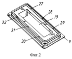
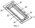
на фиг.1-3 показаны три различных элемента приспособления в соответствии с настоящим изобретением;
на фиг. 4 показаны три скрепленные между собой элемента приспособления, приведенные также на фиг.1-3;
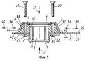
на фиг. 5 приведено поперечное сечение приспособления, закрепленного на стенке приборного шкафа.Below the present invention will be described in more detail with reference to examples of its implementation, as well as with reference to the accompanying drawings, which depict the following:
1 to 3 show three different elements of the device in accordance with the present invention;
in FIG. 4 shows three fastened together fixture elements, also shown in FIGS. 1-3;
in FIG. 5 shows a cross section of a fixture mounted on the wall of the instrument cabinet.
На фиг. 5 показано уплотняющее приспособление, которое используется при выполнении переходов для кабелей и труб и которое включает корпус 1 и один модуль, или большее число модулей 2, выполненный из сжимаемого материала и имеющий аксиально проходящий канал 3, через который необходимо пропускать кабель или трубу с возможностью герметичного уплотнения к соответствующим каналам модулей, при этом в корпусе установлен с возможностью герметичного уплотнения один модуль или большее число модулей. На фиг.5 показан только один модуль 2. In FIG. 5 shows a sealing device that is used when making transitions for cables and pipes and which includes a housing 1 and one module, or
В соответствии с настоящим изобретением, корпус приспособления включает первый элемент 4 и второй элемент 5, имеющие отверстие 6, 7 и предназначенные для закрепления на соответствующих сторонах стены 8, в которой также выполнено отверстие 34. Эти элементы корпуса можно выполнять из листового металла или посредством литья в форму, в зависимости от ряда факторов и, в частности, от их размеров. В альтернативном варианте исполнения элементы корпуса могут также изготавливаться из пластикового материала. In accordance with the present invention, the device body includes a
Между первым и вторым элементами корпуса 4, 5 установлен третий элемент корпуса 9, выполненный в виде части из сжимаемого материала, например резинового материала или аналогичного ему материала, и имеющий отверстие 10, имеющее по существу тот же размер, что и отверстие 6, 7 в соответствующих элементах корпуса 4, 5. Предпочтительно использовать для этих целей резиновый материал, несмотря на тот факт, что на практике могут использоваться и другие материалы, например сжимаемые пластиковые материалы. Between the first and second elements of the
Отверстие 10, выполненное в резиновой части, предназначено для размещения модуля 2 или нескольких модулей, в соответствии с вышеизложенным в предшествующей части описания настоящей заявки и в соответствии с вариантом исполнения, проиллюстрированным на фиг.5. Область 11, показанная на фиг.5 и густо заштрихованная линиями, соответствует положению вышеупомянутых отслаиваемых слоев. Подобные модули 3 выпускаются промышленностью и изготавливаются, например, из резинового материала типа Roxylon, имеющего показатели твердости, соответствующие 80 ± 5o по Шору А.The
Первый и второй элементы корпуса 4, 5 могут соединяться друг с другом, т.е. может обеспечиваться из сближение. Резиновая часть 9 имеет такие размеры, чтобы обеспечивать сжатие в направлении совмещения 12 при соединении между собой первого и второго элементов корпуса, см. фиг.5. The first and second elements of the
В соответствии с одним из предпочтительных вариантов реализации настоящего изобретения, первый элемент корпуса 4 снабжен по существу U-образным поперечным сечением. Резиновая часть имеет аналогичную форму и предназначена для установки в U-образном элементе в непосредственном контакте со стеной 8, сквозь которую необходимо выполнить переход для кабеля или трубы. Резиновый материал, из которого выполняется часть 9, имеет по существу те же самые показатели твердости, что и резиновый материал модуля. Так, например, резиновая часть может выполняться из так называемой резины SBR или бутадиен-стирольного каучука. При этом резиновая часть должна иметь такие показатели твердости, чтобы обеспечить сжатие модуля/модулей и герметичное их прилегание к соответствующему кабелю или трубе. According to one preferred embodiment of the present invention, the first element of the
В соответствии с другим предпочтительным вариантом реализации настоящего изобретения, первый элемент корпуса 4 и резиновая часть 9 снабжены сквозными отверстиями 13-18, 27-32 для установки в них винтов 19, 20. Второй элемент корпуса 5 снабжен втулками с резьбой под винты 21-26 или отверстиями с резьбой под винты, при этом резьба соответствует резьбе винтов, что позволяет соединять между собой первый и второй элементы корпуса. According to another preferred embodiment of the present invention, the
Сборка уплотняющего приспособления осуществляется следующим образом. Второй элемент конструкции 5 устанавливается с задней стороны 33 стены 8, напротив выполненного в этой стене отверстия 34. Затем резиновая часть 9 и первый элемент корпуса 4 устанавливаются с передней стороны 35 стены, после чего производится первоначальное закрепление винтов 19, 20 с тем, чтобы обеспечить целостность образованной конструкции. The assembly of the sealing device is as follows. The second
После этого в отверстие резиновой части устанавливаются модули. Эта рабочая операция сборки проиллюстрирована на фиг.5, хотя на фигуре не показан сам кабель или труба, установленный в канале 3 модуля 2. Следует отметить, что кабели или трубы пропускаются через соответствующие каналы модулей именно в процессе выполнения этой рабочей операции сборки. After that, the modules are installed in the hole of the rubber part. This assembly operation is illustrated in FIG. 5, although the cable or pipe mounted in channel 3 of
При выполнении следующей рабочей операции производится окончательное надежное закрепление винтов, посредством чего обеспечивается сжатие резиновой части в направлении совмещения 12. Резиновая часть в результате этого будет оказывать давление на модуль в направлении, указанном на фиг.5 стрелкой 36. Резиновая часть также оказывает давление на боковые стенки 37, 38 первого элемента конструкции в направлении, указанном стрелками 39, 40. When performing the next work step, the screws are finally securely fixed, thereby compressing the rubber part in the
Под воздействием давления, оказываемого резиновой частью на модули, эти модули будут сжиматься и обеспечивать их герметичное прилегание к соответствующим кабелям или трубам. Under the influence of pressure exerted by the rubber part on the modules, these modules will be compressed and ensure their tight fit to the corresponding cables or pipes.
В результате соединения элементов корпуса фланцы 41, 42 первого элемента корпуса приводятся в непосредственный контакт с фланцами 43, 44 резиновой части. As a result of the connection of the housing elements, the
Из приведенного выше описания становится очевидным, что первый элемент конструкции и резиновая часть обеспечивают выполнение: а) уплотнения между резиновой частью и стеной, b) уплотнения между резиновой частью и первым элементом корпуса, с) уплотнения между резиновой частью и модулем или несколькими модулями и d) уплотнения между соответствующими модулями и соответствующим кабелем и трубой. From the above description, it becomes apparent that the first structural member and the rubber part provide: a) seals between the rubber part and the wall, b) seals between the rubber part and the first housing element, c) seals between the rubber part and the module or several modules, and d ) seals between the respective modules and the corresponding cable and pipe.
Таким образом, приспособление в соответствии с настоящим изобретением не требует использования расширительного элемента, упомянутого во вводной части описания, а также выполнения соответствующих рабочих операций. Thus, the device in accordance with the present invention does not require the use of the expansion element mentioned in the introductory part of the description, as well as the implementation of the corresponding work steps.
Настоящее изобретение было рассмотрено на примерах его реализации, проиллюстрированных с помощью сопровождающих чертежей. The present invention has been described with examples of its implementation, illustrated using the accompanying drawings.
Несложно видеть, однако, что на практике для упомянутых целей могут использоваться и другие типы винтовых соединений или зажимных соединений. Внешняя форма корпуса в альтернативном варианте исполнения может быть задана квадратной или круглой, хотя отверстие резиновой части следует предпочтительно выполнять прямоугольным по форме. Отверстие в элементах корпуса и резиновой части должно соответствовать числу и форме устанавливаемых в них модулей. Несложно также видеть, что форма каждого из трех элементов корпуса в общем случае может быть применена для конкретного варианта использования этих элементов. It is easy to see, however, that in practice other types of screw joints or clamping joints can be used for the mentioned purposes. The external shape of the housing in an alternative embodiment may be defined as square or round, although the opening of the rubber part should preferably be rectangular in shape. The hole in the elements of the housing and the rubber part must correspond to the number and shape of the modules installed in them. It is also easy to see that the shape of each of the three elements of the housing in the general case can be applied to a specific use case of these elements.
Таким образом, не следует считать, что настоящее изобретение ограничивается по объему вышеописанными и вышепроиллюстрированными примерами его реализации, поскольку в него могут быть внесены многочисленные изменения и модификации, не выходящие за его объем, определяемый приводящейся ниже формулой изобретения. Thus, it should not be considered that the present invention is limited in scope by the above-described and above-illustrated examples of its implementation, since numerous changes and modifications may be made therein without departing from its scope as defined by the following claims.
Claims (3)
Applications Claiming Priority (2)
| Application Number | Priority Date | Filing Date | Title |
|---|---|---|---|
| SE9703035A SE510210C2 (en) | 1997-08-22 | 1997-08-22 | Sealing device for cable and pipe penetrations |
| SE9703035-7 | 1997-08-22 |
Publications (2)
| Publication Number | Publication Date |
|---|---|
| RU98115980A RU98115980A (en) | 2000-06-10 |
| RU2198337C2 true RU2198337C2 (en) | 2003-02-10 |
Family
ID=20408010
Family Applications (1)
| Application Number | Title | Priority Date | Filing Date |
|---|---|---|---|
| RU98115980/06A RU2198337C2 (en) | 1997-08-22 | 1998-08-21 | Sealing unit for cable and pipe joints |
Country Status (13)
| Country | Link |
|---|---|
| US (1) | US6149164A (en) |
| EP (1) | EP0898106B1 (en) |
| JP (1) | JP3929181B2 (en) |
| KR (1) | KR100517751B1 (en) |
| CN (1) | CN1075614C (en) |
| AT (1) | ATE235016T1 (en) |
| DE (1) | DE69812252T2 (en) |
| DK (1) | DK0898106T3 (en) |
| ES (1) | ES2191921T3 (en) |
| NO (1) | NO321778B1 (en) |
| RU (1) | RU2198337C2 (en) |
| SE (1) | SE510210C2 (en) |
| SG (1) | SG70111A1 (en) |
Cited By (1)
| Publication number | Priority date | Publication date | Assignee | Title |
|---|---|---|---|---|
| RU2697585C2 (en) * | 2015-03-17 | 2019-08-15 | Рокстек Аб | Sealing device |
Families Citing this family (28)
| Publication number | Priority date | Publication date | Assignee | Title |
|---|---|---|---|---|
| DE19959021B4 (en) * | 1999-12-08 | 2004-04-08 | Robert Bosch Gmbh | Proportional solenoid valve |
| WO2003023922A2 (en) | 2001-09-13 | 2003-03-20 | Triton Technology Systems, Inc. | A tooless self closing floor grommet closure for cable openings |
| SE519393C2 (en) * | 2002-01-22 | 2003-02-25 | Roxtec Int Ab | Frame, for cable entry or similar, provided with a breakable cover |
| US6532877B1 (en) * | 2002-01-22 | 2003-03-18 | Stanrail Corporation | Railroad car roof panel and skylight assembly |
| SE526317C2 (en) * | 2003-02-05 | 2005-08-23 | Roxtec Ab | Socket for cable entry, pipe entry, etc. |
| EP1519092A1 (en) * | 2003-09-24 | 2005-03-30 | Tony Ekat | Method for the sealing of pipes in wallpassages |
| US7121589B2 (en) * | 2003-09-24 | 2006-10-17 | Norwesco, Inc. | Tank fitting and method of use |
| US7355130B2 (en) * | 2004-04-09 | 2008-04-08 | Siemens Information And Communication Networks, Inc. | Cable sealing device |
| SE528691C2 (en) | 2004-12-08 | 2007-01-23 | Roxtec Ab | Frame for receiving one or more resilient modules and compression procedure for one or more resilient modules forming cable passages, pipe passages or the like |
| DE102005062655B3 (en) * | 2005-12-21 | 2007-03-01 | Gk-System Gmbh | Sealing device for encased cables, lines and tubes has at least one limiting surface of module pack receiver formed by separate part-element |
| CN100446369C (en) * | 2006-01-27 | 2008-12-24 | 中国海洋石油总公司 | Strong electric-signal cable deck-piercing apparatus |
| US7723622B2 (en) * | 2007-05-22 | 2010-05-25 | Panduit Corp. | Sealing assembly |
| US7507912B1 (en) | 2007-10-01 | 2009-03-24 | Upsite Technologies, Inc. | Grommet for cables |
| SE533744C2 (en) | 2009-02-04 | 2010-12-21 | Roxtec Ab | Pipe or cable entry with modularized modules |
| DE102009030887B4 (en) | 2009-06-29 | 2022-01-05 | Robert Bosch Gmbh | Valve arrangement |
| WO2012059106A2 (en) * | 2010-11-02 | 2012-05-10 | Blücher Metal A/S | Ductwork |
| CN102767646B (en) * | 2012-07-03 | 2015-10-28 | 朱新平 | A kind of long cable section of ingoing line seal arrangement and there is the distribution box of sealing device |
| CN102927374B (en) * | 2012-10-24 | 2014-09-17 | 中国船舶重工集团公司第七○二研究所 | Water seal treatment device for ship model deck lead opening |
| CN103486264B (en) * | 2013-10-11 | 2015-06-10 | 中国工程物理研究院总体工程研究所 | Cable trench sealing device |
| CN103822027A (en) * | 2014-03-04 | 2014-05-28 | 国网上海市电力公司 | Cable hole plugging device |
| TWD171248S (en) * | 2014-07-29 | 2015-10-21 | 智易科技股份有限公司 | Wired cable management device |
| US9879781B2 (en) * | 2015-03-06 | 2018-01-30 | Ford Global Technologies, Llc | Plated sealing system for vehicle assembly |
| EP3093938B1 (en) * | 2015-05-12 | 2021-07-14 | Siemens Energy Global GmbH & Co. KG | High voltage implementation system |
| CN105318120A (en) * | 2015-06-09 | 2016-02-10 | 王思奇 | Flange connection piece |
| CN105066074A (en) * | 2015-08-26 | 2015-11-18 | 江苏新广联光电股份有限公司 | Power line fixing device |
| DE102018101790A1 (en) * | 2018-01-26 | 2019-08-01 | Harting Electric Gmbh & Co. Kg | sealing insert |
| SE543875C2 (en) * | 2020-02-04 | 2021-08-17 | Roxtec Ab | Transit for cables or pipes through a partition |
| CN115642546B (en) * | 2022-12-26 | 2023-04-18 | 西北电子装备技术研究所(中国电子科技集团公司第二研究所) | Glove box and line-passing sealing structure thereof |
Family Cites Families (8)
| Publication number | Priority date | Publication date | Assignee | Title |
|---|---|---|---|---|
| US849883A (en) * | 1905-07-20 | 1907-04-09 | Whitlock Coil Pipe Company | Flanged metal pipe. |
| US3779585A (en) * | 1972-11-17 | 1973-12-18 | Vilter Manufacturing Corp | Sealing means for an aperture in a panel or the like |
| US4193162A (en) * | 1977-10-20 | 1980-03-18 | Patents And Developments A/S | Flexible bushings |
| DE2909890C2 (en) * | 1979-03-14 | 1982-05-27 | System- Und Verfahrenstechnik Verwaltungsgesellschaft Mbh, 2105 Seevetal | Device for shielding high-frequency electrical and electromagnetic waves in tight bushings for bundles of cables through a wall |
| SU1029294A1 (en) * | 1981-01-04 | 1983-07-15 | Чирчикское Отделение Всесоюзного Научно-Исследовательского Проектно-Конструкторского Технологического Института Трансформаторостроения | Hermetic lead-in mode |
| DE8913702U1 (en) * | 1989-11-20 | 1990-02-08 | Wolff, Anton, Dipl.-Ing., 3492 Brakel, De | |
| FR2674929B1 (en) * | 1991-04-03 | 1995-01-06 | Peugeot | WATERPROOF CONNECTION DEVICE BETWEEN A WALL AND AN ELEMENT THROUGH THIS WALL. |
| US5697194A (en) * | 1996-06-18 | 1997-12-16 | Psi Telecommunications, Inc. | Modular seal assembly for a wall opening |
-
1997
- 1997-08-22 SE SE9703035A patent/SE510210C2/en not_active IP Right Cessation
-
1998
- 1998-08-14 DE DE69812252T patent/DE69812252T2/en not_active Expired - Lifetime
- 1998-08-14 EP EP98850131A patent/EP0898106B1/en not_active Expired - Lifetime
- 1998-08-14 AT AT98850131T patent/ATE235016T1/en active
- 1998-08-14 DK DK98850131T patent/DK0898106T3/en active
- 1998-08-14 ES ES98850131T patent/ES2191921T3/en not_active Expired - Lifetime
- 1998-08-19 SG SG1998003139A patent/SG70111A1/en unknown
- 1998-08-20 KR KR10-1998-0033710A patent/KR100517751B1/en not_active IP Right Cessation
- 1998-08-21 NO NO19983862A patent/NO321778B1/en not_active IP Right Cessation
- 1998-08-21 CN CN98118649A patent/CN1075614C/en not_active Expired - Lifetime
- 1998-08-21 RU RU98115980/06A patent/RU2198337C2/en active
- 1998-08-21 US US09/138,228 patent/US6149164A/en not_active Expired - Lifetime
- 1998-08-24 JP JP23722698A patent/JP3929181B2/en not_active Expired - Fee Related
Cited By (1)
| Publication number | Priority date | Publication date | Assignee | Title |
|---|---|---|---|---|
| RU2697585C2 (en) * | 2015-03-17 | 2019-08-15 | Рокстек Аб | Sealing device |
Also Published As
| Publication number | Publication date |
|---|---|
| JPH11148557A (en) | 1999-06-02 |
| JP3929181B2 (en) | 2007-06-13 |
| DE69812252T2 (en) | 2003-09-25 |
| EP0898106B1 (en) | 2003-03-19 |
| SE9703035L (en) | 1999-02-23 |
| CN1210218A (en) | 1999-03-10 |
| DE69812252D1 (en) | 2003-04-24 |
| KR100517751B1 (en) | 2005-11-21 |
| ATE235016T1 (en) | 2003-04-15 |
| NO983862L (en) | 1999-02-23 |
| ES2191921T3 (en) | 2003-09-16 |
| SE9703035D0 (en) | 1997-08-22 |
| DK0898106T3 (en) | 2003-06-30 |
| SE510210C2 (en) | 1999-05-03 |
| SG70111A1 (en) | 2000-01-25 |
| CN1075614C (en) | 2001-11-28 |
| NO321778B1 (en) | 2006-07-03 |
| US6149164A (en) | 2000-11-21 |
| KR19990023723A (en) | 1999-03-25 |
| NO983862D0 (en) | 1998-08-21 |
| EP0898106A1 (en) | 1999-02-24 |
Similar Documents
| Publication | Publication Date | Title |
|---|---|---|
| RU2198337C2 (en) | Sealing unit for cable and pipe joints | |
| RU98115980A (en) | SEALING DEVICE FOR TRANSITIONS OF CABLES AND PIPES | |
| US5971444A (en) | Through wall connector | |
| CA2549047C (en) | Lead-through means for cables or pipes | |
| US4429907A (en) | Pipe coupler | |
| JPS61211508A (en) | Clamp for repairing pipe | |
| RU2082268C1 (en) | Cable sleeve | |
| CA2523447A1 (en) | Faucet quick install nut | |
| RU2339140C1 (en) | Frame and method for locking one or more resilient modules for cable entries, pipe passages of similar devices | |
| KR100285532B1 (en) | Cable sleeve consisting of longitudinally divided housing | |
| US4712342A (en) | Fire-sealed lead-through for framed building components | |
| JP2000320736A (en) | Waterproof device of conduit for cable | |
| KR100454565B1 (en) | Waterproof device of pipe for wiring communication and electric power cable | |
| KR200391564Y1 (en) | apparatus for connecting sewer pipes with a flange | |
| KR200308856Y1 (en) | multi-layer packing for watertight strengthen | |
| EP1615311B1 (en) | Watertight feedthrough wall fitting | |
| CN221097795U (en) | Connecting mechanism of double sealing structure | |
| KR200236115Y1 (en) | a | |
| CN217519424U (en) | Rapid repair device for repairing cement pipe joint | |
| JPH11117338A (en) | Connection device for underwater structure | |
| JP3095025U (en) | Cable conduit fixing device | |
| KR200282527Y1 (en) | Waterproof device of pipe for wiring communication and electric power cable | |
| KR200352794Y1 (en) | Duct coupling equipment | |
| KR0129905Y1 (en) | Conduit insertion sleeve | |
| SU1582247A1 (en) | Hermetic lead-in unit |