RU2180813C2 - Nail for fixation of position and shape of broken long bones - Google Patents
Nail for fixation of position and shape of broken long bones Download PDFInfo
- Publication number
- RU2180813C2 RU2180813C2 RU97119067/14A RU97119067A RU2180813C2 RU 2180813 C2 RU2180813 C2 RU 2180813C2 RU 97119067/14 A RU97119067/14 A RU 97119067/14A RU 97119067 A RU97119067 A RU 97119067A RU 2180813 C2 RU2180813 C2 RU 2180813C2
- Authority
- RU
- Russia
- Prior art keywords
- nail
- section
- bone
- rod
- expansion
- Prior art date
Links
Images


Classifications
-
- A—HUMAN NECESSITIES
- A61—MEDICAL OR VETERINARY SCIENCE; HYGIENE
- A61B—DIAGNOSIS; SURGERY; IDENTIFICATION
- A61B17/00—Surgical instruments, devices or methods, e.g. tourniquets
- A61B17/56—Surgical instruments or methods for treatment of bones or joints; Devices specially adapted therefor
- A61B17/58—Surgical instruments or methods for treatment of bones or joints; Devices specially adapted therefor for osteosynthesis, e.g. bone plates, screws, setting implements or the like
- A61B17/68—Internal fixation devices, including fasteners and spinal fixators, even if a part thereof projects from the skin
- A61B17/72—Intramedullary pins, nails or other devices
- A61B17/7233—Intramedullary pins, nails or other devices with special means of locking the nail to the bone
- A61B17/7258—Intramedullary pins, nails or other devices with special means of locking the nail to the bone with laterally expanding parts, e.g. for gripping the bone
- A61B17/7275—Intramedullary pins, nails or other devices with special means of locking the nail to the bone with laterally expanding parts, e.g. for gripping the bone with expanding cylindrical parts
-
- A—HUMAN NECESSITIES
- A61—MEDICAL OR VETERINARY SCIENCE; HYGIENE
- A61B—DIAGNOSIS; SURGERY; IDENTIFICATION
- A61B17/00—Surgical instruments, devices or methods, e.g. tourniquets
- A61B17/56—Surgical instruments or methods for treatment of bones or joints; Devices specially adapted therefor
- A61B17/58—Surgical instruments or methods for treatment of bones or joints; Devices specially adapted therefor for osteosynthesis, e.g. bone plates, screws, setting implements or the like
- A61B17/68—Internal fixation devices, including fasteners and spinal fixators, even if a part thereof projects from the skin
- A61B17/72—Intramedullary pins, nails or other devices
- A61B17/7233—Intramedullary pins, nails or other devices with special means of locking the nail to the bone
- A61B17/7258—Intramedullary pins, nails or other devices with special means of locking the nail to the bone with laterally expanding parts, e.g. for gripping the bone
- A61B17/7266—Intramedullary pins, nails or other devices with special means of locking the nail to the bone with laterally expanding parts, e.g. for gripping the bone with fingers moving radially outwardly
-
- A—HUMAN NECESSITIES
- A61—MEDICAL OR VETERINARY SCIENCE; HYGIENE
- A61B—DIAGNOSIS; SURGERY; IDENTIFICATION
- A61B17/00—Surgical instruments, devices or methods, e.g. tourniquets
- A61B2017/00535—Surgical instruments, devices or methods, e.g. tourniquets pneumatically or hydraulically operated
- A61B2017/00539—Surgical instruments, devices or methods, e.g. tourniquets pneumatically or hydraulically operated hydraulically
-
- A—HUMAN NECESSITIES
- A61—MEDICAL OR VETERINARY SCIENCE; HYGIENE
- A61B—DIAGNOSIS; SURGERY; IDENTIFICATION
- A61B17/00—Surgical instruments, devices or methods, e.g. tourniquets
- A61B2017/00535—Surgical instruments, devices or methods, e.g. tourniquets pneumatically or hydraulically operated
- A61B2017/00544—Surgical instruments, devices or methods, e.g. tourniquets pneumatically or hydraulically operated pneumatically
-
- A—HUMAN NECESSITIES
- A61—MEDICAL OR VETERINARY SCIENCE; HYGIENE
- A61B—DIAGNOSIS; SURGERY; IDENTIFICATION
- A61B17/00—Surgical instruments, devices or methods, e.g. tourniquets
- A61B2017/00535—Surgical instruments, devices or methods, e.g. tourniquets pneumatically or hydraulically operated
- A61B2017/00557—Surgical instruments, devices or methods, e.g. tourniquets pneumatically or hydraulically operated inflatable
Landscapes
- Health & Medical Sciences (AREA)
- Orthopedic Medicine & Surgery (AREA)
- Surgery (AREA)
- Life Sciences & Earth Sciences (AREA)
- Heart & Thoracic Surgery (AREA)
- Animal Behavior & Ethology (AREA)
- Engineering & Computer Science (AREA)
- Biomedical Technology (AREA)
- Neurology (AREA)
- Medical Informatics (AREA)
- Molecular Biology (AREA)
- Nuclear Medicine, Radiotherapy & Molecular Imaging (AREA)
- General Health & Medical Sciences (AREA)
- Public Health (AREA)
- Veterinary Medicine (AREA)
- Prostheses (AREA)
- Surgical Instruments (AREA)
- Orthopedics, Nursing, And Contraception (AREA)
Abstract
Description
Изобретение относится к гвоздю для фиксации положения и формы сломанных длинных костей. The invention relates to a nail for fixing the position and shape of broken long bones.
До настоящего времени для внутренней стабилизации сломанных длинных костей используются относительно большие стальные гвозди, имеющие заданное заранее U-образное или V-образное поперечное сечение. Гвозди стабилизируют кости в соответствии с принципом обеспечения поддержки в трех точках, а именно в начале, в конце и в средней секции гвоздя. Для того, чтобы расположить такие гвозди, через поверхность кости, а затем через медуллярную полость кости должны быть сделаны большие отверстия, совпадающие с диаметром имплантированного гвоздя. Этот способ имеет следующий недостаток: почти все медуллярные полости должны рассверливаться для того, чтобы сделать такое отверстие, и в результате, в частности, ухудшается снабжение кости кровью. Кроме того, из-за поддержки в трех точках, усилие передается через сравнительно малую область, и для обеспечения вращательной стабильности необходимо использовать дополнительные механизмы, такие как скрепляющие шурупы и т.п. To date, relatively large steel nails having a predetermined U-shaped or V-shaped cross section are used to stabilize broken long bones internally. Nails stabilize bones in accordance with the principle of providing support at three points, namely at the beginning, at the end and in the middle section of the nail. In order to position such nails, large openings must be made across the surface of the bone, and then through the medullary cavity of the bone, matching the diameter of the implanted nail. This method has the following drawback: almost all medullary cavities must be reamed in order to make such an opening, and as a result, in particular, blood supply to the bone is impaired. In addition, due to support at three points, the force is transmitted through a relatively small area, and additional mechanisms, such as fastening screws, etc., must be used to ensure rotational stability.
Удаление внутримедуллярного гвоздя после того, как кость срослась, также является процедурой, требующей сравнительно высокой степени усилий. Гвоздь заклинен в медуллярной полости и должен быть выбит из полости с использованием специальных инструментов и с приложением сравнительно больших усилий. Опять-таки в этом процессе медуллярная полость может испытывать значительные повреждения. Removing the intramedullary nail after the bone has grown together is also a procedure requiring a relatively high degree of effort. The nail is stuck in the medullary cavity and must be knocked out of the cavity using special tools and with the application of relatively large forces. Again, in this process, the medullary cavity may experience significant damage.
Из DE-C-32 01 056 известен внутримедуллярный гвоздь, в котором стержень состоит из полого корпуса, выполненного из сплава с памятью формы, который может принимать две возможные формы в зависимости от температуры. Затем, когда он уже установлен, внутримедуллярный гвоздь может быть преобразован из имеющего малое поперечное сечение в имеющий большое поперечное сечение, и наоборот. Недостаток этого существующего типа внутримедуллярного гвоздя заключается в том, что применение тепла, требуемого для расширения диаметра стержня гвоздя, также вызывает термический стресс в кости и в костном мозге. An intramedullary nail is known from DE-C-32 01 056, in which the shaft consists of a hollow body made of an alloy with shape memory, which can take two possible shapes depending on temperature. Then, when it is already installed, the intramedullary nail can be transformed from having a small cross section to having a large cross section, and vice versa. The disadvantage of this existing type of intramedullary nail is that the application of the heat required to expand the diameter of the nail shaft also causes thermal stress in the bone and bone marrow.
Гвоздь в соответствии с ограничительной частью п.1 формулы изобретения известен из патента США 5102413. В этом известном гвозде единая расширяющаяся камера окружает основное тело гвоздя полностью. A nail in accordance with the preamble of claim 1 is known from US Pat. No. 5,102,413. In this known nail, a single expanding chamber completely surrounds the main body of the nail.
Задачей настоящего изобретения является создание гвоздя для фиксации положения и формы сломанных длинных костей, который обеспечивает хорошую стабилизацию, может быть имплантирован без значительных повреждений в медуллярной полости и который также не создает никакого термического стресса в кости и костном мозге. An object of the present invention is to provide a nail for fixing the position and shape of broken long bones, which ensures good stabilization, can be implanted without significant damage to the medullary cavity and which also does not create any thermal stress in the bone and bone marrow.
Эта задача решается в соответствии с изобретением с помощью гвоздя, имеющего характеристики, описанные в п. 1 формулы изобретения. This problem is solved in accordance with the invention with a nail having the characteristics described in paragraph 1 of the claims.
В соответствии с настоящим изобретением, гвоздь в нерасширенном состоянии, т. е. пока он еще имеет малый диаметр, может быть введен через сравнительно небольшой корковый канал внутрь медуллярной полости. Нет необходимости рассверливать медуллярную полость, повреждая тем самым большие ее секции. Когда гвоздь полностью имплантирован, поперечное сечение расширяется без применения тепла до требуемого размера в целях стабилизации сломанной кости. Поддерживающие усилия тогда распределяются по большой области. Вращательная стабильность также достигается через контакт поверхностей и через последующую адаптацию к данной форме медуллярной полости. In accordance with the present invention, a nail in an unexpanded state, that is, while it still has a small diameter, can be inserted through a relatively small cortical canal into the medullary cavity. There is no need to drill a medullary cavity, thereby damaging its large sections. When the nail is fully implanted, the cross section expands without applying heat to the required size in order to stabilize the broken bone. Supporting efforts are then distributed over a large area. Rotational stability is also achieved through contact of surfaces and through subsequent adaptation to a given shape of the medullary cavity.
Поскольку увеличение поперечного сечения обратимо, как описано в п. 2 формулы изобретения, имплантант может быть удален способом, который особенно безопасен для тканей, когда кость срастается. Since the increase in cross section is reversible, as described in
Дальнейшие выгодные выполнения изобретения являются предметом остальных зависимых пунктов формулы изобретения. Further advantageous embodiments of the invention are the subject of the remaining dependent claims.
Предпочтительные выполнения изобретения теперь будут описаны на основе приложенных чертежей, которые показывают:
фиг. 1 - выполнение гвоздя в соответствии с изобретением, показанного в продольном сечении;
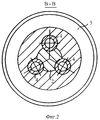
фиг. 2 - поперечное сечение по линии В-В на фиг.1;
фиг. 3 - поперечное сечение по линии А-А на фиг.1;
фиг. 4 - еще одно поперечное сечение по линии А-А с убранными и расширенными элементами расширения;
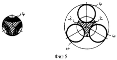
фиг. 5 - поперечное сечение, соответствующее сечению на фиг. 4, другого выполнения основного сечения стержня и элементов расширения;
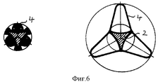
фиг. 6 - поперечное сечение, соответствующее сечению на фиг. 4, другого выполнения основного сечения стержня и элементов расширения;
фиг. 7 - поперечное сечение, соответствующее сечению на фиг. 4, выполнения, имеющего центральный элемент расширения, с ребрами жесткости, радиально выступающими в осевом направлении, прикрепленными снаружи;
фиг. 8 - поперечное сечение, соответствующее сечению на фиг. 4, выполнения, одинакового с выполнением на фиг. 7, имеющего ребра жесткости, выполненные вместе с центральным элементом расширения в конфигурации, одинаковой с конфигурацией на фиг. 7;
фиг. 9 - поперечное сечение, соответствующее сечению на фиг. 4, выполнения с элементами расширения, сложенными на нем в нерасширенном состоянии;
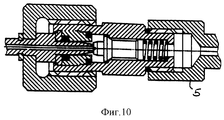
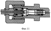
фиг. 10 - выполнение клапана в продольном сечении, использованного в головке гвоздя, показанного на фиг. 1;
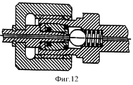
фиг. 11 - вид, соответствующий виду на фиг. 10, выполнения, в котором головка гвоздя изготовлена как часть клапана;
фиг. 12 - выполнение, одинаковое с выполнением на фиг. 11, имеющее сферу вместо поршня как уплотняющее тело;
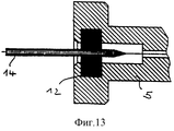
фиг. 13 - выполнение, имеющее пригодную для протыкания мембрану вместо клапана;
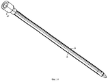
фиг. 14 - вид в изометрии гвоздя по фиг. 1;
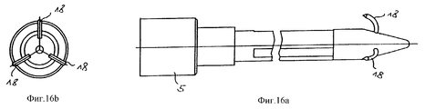
фиг. 15а и 15b - выполнение гвоздя в соответствии с изобретением в продольном сечении и частичном виде сбоку соответственно с винтовым концом;
фиг. 16а и 16b - вид сбоку и вид спереди, со стороны винтового конца гвоздя, имеющего выступающие элементы на конце.Preferred embodiments of the invention will now be described based on the attached drawings, which show:
FIG. 1 - the implementation of the nail in accordance with the invention, shown in longitudinal section;
FIG. 2 is a cross section along line BB in FIG. 1;
FIG. 3 is a cross section along line AA in figure 1;
FIG. 4 is another cross section along the line AA with the removed and expanded expansion elements;
FIG. 5 is a cross section corresponding to that of FIG. 4, another embodiment of the main section of the rod and expansion elements;
FIG. 6 is a cross section corresponding to that of FIG. 4, another embodiment of the main section of the rod and expansion elements;
FIG. 7 is a cross section corresponding to that of FIG. 4, an embodiment having a central expansion member, with stiffening ribs radially protruding axially attached externally;
FIG. 8 is a cross section corresponding to that of FIG. 4, of the same design as in FIG. 7 having stiffeners made together with the central expansion member in a configuration identical to that in FIG. 7;
FIG. 9 is a cross section corresponding to that of FIG. 4, performing with extension elements folded thereon in an unexpanded state;
FIG. 10 shows an embodiment of a valve in longitudinal section used in the nail head shown in FIG. 1;
FIG. 11 is a view corresponding to that of FIG. 10, an embodiment in which a nail head is fabricated as part of a valve;
FIG. 12 is an embodiment identical to that of FIG. 11 having a sphere instead of a piston as a sealing body;
FIG. 13 is an embodiment having a piercing membrane instead of a valve;
FIG. 14 is an isometric view of the nail of FIG. 1;
FIG. 15a and 15b show a nail in accordance with the invention in longitudinal section and in partial side view, respectively, with a screw end;
FIG. 16a and 16b are a side view and a front view, from the side of the screw end of a nail having protruding elements at the end.
Гвоздь для длинных костей, как показано на фиг.1, содержит стержень 1, имеющий центральную основную секцию 2, выполненную предпочтительно из совместимого с тканями пластика. Эта основная секция 2 практически стабильна по своим размерам, но предпочтительно обладает определенной упругостью на изгиб. В выполнении, показанном здесь, она круглая в поперечном сечении и снабжена тремя канавками 3, идущими вдоль по длине и разнесенными на 120o друг от друга снаружи по окружности секции. В этих канавках установлены трубчатые (камероподобные) элементы 4 расширения, также предпочтительно выполненные из совместимого с тканями пластика, которые предпочтительно являются эластично расширяемыми в поперечном сечении. Таким образом, элементы 4 расширения расположены вокруг основной секции 2 и вытянуты по длине стержня 1. При отсутствии внутреннего давления элементы 4 расширения предпочтительно не выступают из внешнего контура основной секции 2. Головка 5 гвоздя выполнена как приемник для наполняющего и разгружающего клапана, как показано на фиг. 10, и снабжена соответствующей резьбой 6 для клапана. На конце гвоздя расположена концевая насадка 7, предпочтительно конической формы, для облегчения введения гвоздя. Насадка предпочтительно содержит металлический штырь 8, который виден при рентгеноскопии, облегчая введение гвоздя. Также возможно использование металлической полоски, тянущейся по всей длине гвоздя.The long bone nail, as shown in FIG. 1, comprises a shaft 1 having a central
Когда в элементах 4 расширения, каждый из которых имеет форму камеры, при нахождении их в кости создается внутреннее давление путем закачивания в них газа или жидкости - с медицинской точки зрения идеален физиологический раствор соли - они расширяются в радиальном направлении, как показано на фиг. 4, так что поперечное сечение стержня 1 гвоздя увеличивается по всей окружности. Формируется структура с формой примерно в виде звезды в поперечном сечении. Части, выступающие дальше всего, заполняют только часть описанного вокруг них поперечного сечения, так что остается достаточно пространства, в которое может быть перемещен костный мозг. На тип и размер области контакта с костью можно повлиять путем изменения поперечного сечения элементов расширения. Упругость на изгиб основной секции 2 и, таким образом, стержня 1 в целом позволяет стержню также следовать неровностям медуллярной полости и совместно с характером элементов расширения гарантирует однородный контакт с костью в продольном направлении. When in the
Фиг. 5 показывает выполнение, в котором элементы расширения, сходные с камерами, имеют форму не гибких элементов, но сложенных элементов, которые в этом случае лежат в вогнутых канавках 3 в отсутствие давления. FIG. 5 shows an embodiment in which expansion elements similar to the chambers are in the form of not flexible elements, but folded elements, which in this case lie in the
Фиг. 6 показывает выполнение, в котором элементы расширения сложены в отсутствие давления, и когда они расширены для формирования формы треугольного поперечного сечения с закругленными концами. FIG. 6 shows an embodiment in which expansion elements are folded in the absence of pressure, and when they are expanded to form a triangular cross-section with rounded ends.
Фиг. 7-9 показывают выполнение стержня 1 гвоздя, в котором центральная основная секция в виде, описанном выше, отсутствует. Вместо этого центральный элемент формируется расширяющимся или в состоянии отсутствия давления сложенным трубчатым элементом 4 расширения, расположенным вдоль продольной оси стержня 1. По окружности элемента 4 расширения сформированы вместе с ним или прикреплены к нему ребра 10, расположенные вдоль продольной оси стержня 1 и радиально выступающие наружу за элемент 4, причем упомянутые ребра стабильны по размерам и имеют требуемую упругость на изгиб. Когда на элементы 4 расширения не воздействуют давлением, ребра 10 расположены близко друг к другу и образуют стержень с малым поперечным сечением. Когда элемент 4 расширения наполняется газом или жидкостью, в особенности физиологическим раствором поваренной соли, расширенный в поперечном сечении элемент 4 расширения определяет поперечное сечение стержня гвоздя, и прикрепленные ребра 10, которые являются элементами, контактирующими с костью, продолжают обеспечивать жесткость стержня гвоздя. FIG. 7-9 show the implementation of a nail shaft 1 in which the central main section in the form described above is absent. Instead, the central element is formed by an expanding or in the absence of pressure folded
Гвоздь имеет в своей головке 5 клапан для введения или удаления жидкости или газа с целью увеличения или уменьшения размера поперечного сечения стержня гвоздя. Для расширения стержня гвоздя, например, использован клапан в головке 5 гвоздя, как показано на фиг. 10. В выполнениях, показанных на фиг. 11 и 12, головка 5 гвоздя выполнена таким образом, что она сама является частью клапана. Тот же клапан также используется для устранения давления в элементе или элементах 4 расширения, т.е. для изъятия среды расширения, которой был(и) заполнен(ы) упомянутый(ые) элемент или элементы. The nail has a
В особенно выгодном выполнении изобретения, как показано на фиг. 13, головка 5 гвоздя содержит только пригодную для протыкания мембрану 12 для полой иглы 14, посредством которой жидкость или газ могут быть закачаны внутрь для заполнения элементов расширения. Когда они расширены, полая игла 14 вынимается и пригодная для протыкания мембрана 12 автоматически герметизируется. Для удаления расширяющей жидкости, когда процесс срастания завершен, полая игла снова вводится через мембрану и жидкость снова удаляется. Таким образом элементы 4 расширения могут быть возвращены в нерасширенное состояние, когда гвоздь еще установлен в кости. In a particularly advantageous embodiment of the invention, as shown in FIG. 13, the
Фиг. 14 показывает вид в изометрии гвоздя в продольном сечении фиг. 1. Гвоздь имеет обычную длину от 25 до 35 см в соответствии с длиной бедренной кости. FIG. 14 shows a perspective view of a nail in longitudinal section of FIG. 1. The nail has a normal length of 25 to 35 cm in accordance with the length of the femur.
Фиг. 15а и 15b показывают выполнение гвоздя, имеющего винтовой конец 16, который допускает специальное крепление гвоздя в кости, что осуществляется также приспособлением 18 с распорками, показанным в выполнении, проиллюстрированном на фиг. 16а и 16b. FIG. 15a and 15b show the implementation of a nail having a
В предпочтительной конструкции гвоздь выполнен из материала, который может рассасываться телом. Это делает ненужным удаление гвоздя после того, как срастание закончилось. In a preferred construction, the nail is made of material that can be absorbed by the body. This makes it unnecessary to remove the nail after the fusion has ended.
Claims (7)
Applications Claiming Priority (2)
| Application Number | Priority Date | Filing Date | Title |
|---|---|---|---|
| DE19514758.8 | 1995-04-21 | ||
| DE19514758A DE19514758C2 (en) | 1995-04-21 | 1995-04-21 | Nail for fixing the position and shape of broken tubular bones |
Publications (2)
| Publication Number | Publication Date |
|---|---|
| RU97119067A RU97119067A (en) | 1999-08-27 |
| RU2180813C2 true RU2180813C2 (en) | 2002-03-27 |
Family
ID=7760072
Family Applications (1)
| Application Number | Title | Priority Date | Filing Date |
|---|---|---|---|
| RU97119067/14A RU2180813C2 (en) | 1995-04-21 | 1996-04-19 | Nail for fixation of position and shape of broken long bones |
Country Status (10)
| Country | Link |
|---|---|
| US (1) | US6025537A (en) |
| EP (1) | EP0827385B1 (en) |
| JP (1) | JP3715652B2 (en) |
| CN (1) | CN1183878C (en) |
| AT (1) | ATE196984T1 (en) |
| BR (1) | BR9608183A (en) |
| DE (1) | DE59606028D1 (en) |
| ES (1) | ES2153107T3 (en) |
| RU (1) | RU2180813C2 (en) |
| WO (1) | WO1996032899A1 (en) |
Cited By (2)
| Publication number | Priority date | Publication date | Assignee | Title |
|---|---|---|---|---|
| RU2452426C1 (en) * | 2010-09-30 | 2012-06-10 | Михаил Михайлович Криштал | Rod for fixation of position and shape of tubular bones |
| RU2526242C1 (en) * | 2013-10-03 | 2014-08-20 | Анатолий Петрович Барабаш | Intramedullary blocking device for osteosynthesis |
Families Citing this family (27)
| Publication number | Priority date | Publication date | Assignee | Title |
|---|---|---|---|---|
| EP0912059A3 (en) * | 1992-12-09 | 1999-05-19 | Discovery Communications, Inc. | Terminal with multiple audio and video |
| US20070282443A1 (en) * | 1997-03-07 | 2007-12-06 | Disc-O-Tech Medical Technologies Ltd. | Expandable element |
| EP1905392B1 (en) * | 1997-03-07 | 2011-05-18 | Kyphon SÀRL | System for percutaneous bone and spinal stabilization, fixation and repair |
| US20060271061A1 (en) * | 2001-07-25 | 2006-11-30 | Disc-O-Tech, Ltd. | Deformable tools and implants |
| WO2001054598A1 (en) * | 1998-03-06 | 2001-08-02 | Disc-O-Tech Medical Technologies, Ltd. | Expanding bone implants |
| IL128261A0 (en) * | 1999-01-27 | 1999-11-30 | Disc O Tech Medical Tech Ltd | Expandable element |
| US7621950B1 (en) | 1999-01-27 | 2009-11-24 | Kyphon Sarl | Expandable intervertebral spacer |
| IL147783A0 (en) * | 2002-01-23 | 2002-08-14 | Disc O Tech Medical Tech Ltd | Locking mechanism for intramedulliary nails |
| ES2353689T5 (en) | 2003-03-14 | 2014-08-18 | Depuy Spine, Inc. | Bone cement hydraulic injection device in percutaneous vertebroplasty |
| US8066713B2 (en) | 2003-03-31 | 2011-11-29 | Depuy Spine, Inc. | Remotely-activated vertebroplasty injection device |
| US8415407B2 (en) | 2004-03-21 | 2013-04-09 | Depuy Spine, Inc. | Methods, materials, and apparatus for treating bone and other tissue |
| WO2005030034A2 (en) * | 2003-09-26 | 2005-04-07 | Depuy Spine, Inc. | Device for delivering viscous material |
| US7481841B2 (en) * | 2004-06-30 | 2009-01-27 | Depuy Products, Inc. | Adjustable orthopaedic prosthesis and associated method |
| CN106963464B (en) | 2004-07-30 | 2019-11-05 | 德普伊新特斯产品有限责任公司 | Surgical set |
| US7559951B2 (en) * | 2004-09-30 | 2009-07-14 | Depuy Products, Inc. | Adjustable, remote-controllable orthopaedic prosthesis and associated method |
| US9381024B2 (en) | 2005-07-31 | 2016-07-05 | DePuy Synthes Products, Inc. | Marked tools |
| US9918767B2 (en) | 2005-08-01 | 2018-03-20 | DePuy Synthes Products, Inc. | Temperature control system |
| US8360629B2 (en) | 2005-11-22 | 2013-01-29 | Depuy Spine, Inc. | Mixing apparatus having central and planetary mixing elements |
| WO2008032322A2 (en) | 2006-09-14 | 2008-03-20 | Depuy Spine, Inc. | Bone cement and methods of use thereof |
| WO2008047371A2 (en) | 2006-10-19 | 2008-04-24 | Depuy Spine, Inc. | Fluid delivery system |
| EP2190365A4 (en) * | 2007-05-10 | 2013-09-04 | Oren Globerman | Expandable intramedullary nail for small bone fixation |
| US8556949B2 (en) | 2007-11-14 | 2013-10-15 | DePuy Synthes Products, LLC | Hybrid bone fixation element and methods of using the same |
| US7805920B2 (en) * | 2008-11-13 | 2010-10-05 | The Toro Company | Lawn mower having steeply inclined exit tunnel and battery access through rear face of mower cutting deck |
| WO2011038315A1 (en) * | 2009-09-28 | 2011-03-31 | Zimmer, Inc. | Expandable intramedullary rod |
| US9155578B2 (en) | 2012-02-28 | 2015-10-13 | DePuy Synthes Products, Inc. | Expandable fastener |
| ITTO20120687A1 (en) * | 2012-07-31 | 2014-02-01 | Im Ligure S R L Unipersonale | INTRAMIDOLLAR NAIL. |
| DE102020128512B3 (en) | 2020-10-29 | 2021-11-18 | mechamed GmbH | Prosthetic anchor |
Family Cites Families (10)
| Publication number | Priority date | Publication date | Assignee | Title |
|---|---|---|---|---|
| DE2821785A1 (en) * | 1978-05-18 | 1979-11-22 | Gerhard Dawidowski | Bone fracture compression nail - has distal claw sliding in proximal ones in axial direction, retained by lug |
| US4313434A (en) * | 1980-10-17 | 1982-02-02 | David Segal | Fracture fixation |
| SU1049050A1 (en) * | 1982-01-15 | 1983-10-23 | Киевский Медицинский Институт Им.Акад.А.А.Богомольца | Pin for osteosynthesis |
| FR2629337A1 (en) * | 1988-03-30 | 1989-10-06 | Bigan Michel | Device for intra-osseus sealing of a prosthesis element |
| US5116335A (en) * | 1989-09-18 | 1992-05-26 | Hannon Gerard T | Intramedullary hybrid nail and instrumentation for installation and removal |
| CH680564A5 (en) * | 1989-12-07 | 1992-09-30 | Experimentelle Chirurgie Schwe | |
| US5102413A (en) * | 1990-11-14 | 1992-04-07 | Poddar Satish B | Inflatable bone fixation device |
| US5480403A (en) * | 1991-03-22 | 1996-01-02 | United States Surgical Corporation | Suture anchoring device and method |
| FR2674119B1 (en) * | 1991-03-22 | 1993-06-18 | Fixano Productions | DEVICE FOR GUIDING THE SLIDING OF OSTEOSYNTHESIS SCREWS FOR INTRA-CAPSULAR FRACTURE OF THE FEMUR'S NECK. |
| IT1275300B (en) * | 1995-06-05 | 1997-08-05 | Gruppo Ind Bioimpianti Srl | BLOCKED ENDOMIDOLLAR NAIL SUITABLE FOR FEMORE FRACTURES IN PARTICULAR |
-
1996
- 1996-04-19 WO PCT/EP1996/001652 patent/WO1996032899A1/en active IP Right Grant
- 1996-04-19 EP EP96914958A patent/EP0827385B1/en not_active Expired - Lifetime
- 1996-04-19 JP JP53148696A patent/JP3715652B2/en not_active Expired - Lifetime
- 1996-04-19 CN CNB961946849A patent/CN1183878C/en not_active Expired - Lifetime
- 1996-04-19 RU RU97119067/14A patent/RU2180813C2/en active
- 1996-04-19 BR BR9608183A patent/BR9608183A/en not_active IP Right Cessation
- 1996-04-19 AT AT96914958T patent/ATE196984T1/en active
- 1996-04-19 DE DE59606028T patent/DE59606028D1/en not_active Expired - Fee Related
- 1996-04-19 ES ES96914958T patent/ES2153107T3/en not_active Expired - Lifetime
-
1997
- 1997-10-20 US US08/954,716 patent/US6025537A/en not_active Expired - Lifetime
Cited By (2)
| Publication number | Priority date | Publication date | Assignee | Title |
|---|---|---|---|---|
| RU2452426C1 (en) * | 2010-09-30 | 2012-06-10 | Михаил Михайлович Криштал | Rod for fixation of position and shape of tubular bones |
| RU2526242C1 (en) * | 2013-10-03 | 2014-08-20 | Анатолий Петрович Барабаш | Intramedullary blocking device for osteosynthesis |
Also Published As
| Publication number | Publication date |
|---|---|
| CN1187761A (en) | 1998-07-15 |
| AU724544B2 (en) | 2000-09-28 |
| BR9608183A (en) | 1999-05-04 |
| DE59606028D1 (en) | 2000-11-23 |
| CN1183878C (en) | 2005-01-12 |
| JPH11503639A (en) | 1999-03-30 |
| ATE196984T1 (en) | 2000-11-15 |
| AU5690796A (en) | 1996-11-07 |
| ES2153107T3 (en) | 2001-02-16 |
| US6025537A (en) | 2000-02-15 |
| EP0827385B1 (en) | 2000-10-18 |
| EP0827385A1 (en) | 1998-03-11 |
| JP3715652B2 (en) | 2005-11-09 |
| WO1996032899A1 (en) | 1996-10-24 |
Similar Documents
| Publication | Publication Date | Title |
|---|---|---|
| RU2180813C2 (en) | Nail for fixation of position and shape of broken long bones | |
| US6077265A (en) | Nail for fixing the position and shape of broken long bones | |
| ES2390482T3 (en) | Implant to stabilize vertebrae or bones | |
| JP3650361B2 (en) | Orthopedic implant assembly | |
| JP4394441B2 (en) | Spinal implant | |
| RU2296526C2 (en) | Expandable orthopedic device | |
| US7488337B2 (en) | Apparatus and methods for bone, tissue and duct dilatation | |
| JP5504182B2 (en) | Telescopic expandable sleeve implant | |
| US8556949B2 (en) | Hybrid bone fixation element and methods of using the same | |
| KR101657732B1 (en) | Apparatus for bone restoration of the spine and methods of use | |
| JP2002535080A5 (en) | ||
| US20020032444A1 (en) | Methods and devices for treatment of bone fractures | |
| JP2001258915A (en) | Implant for orthopedic surgery and method for its implantation to bone | |
| KR101505110B1 (en) | Implant for stabilizing vertebrae or bones | |
| CA2218474C (en) | Nail for maintaining the location and shape of broken long bones | |
| RU2452426C1 (en) | Rod for fixation of position and shape of tubular bones | |
| RU100717U1 (en) | ROD FOR FIXING THE POSITION AND FORM OF TUBULAR BONES | |
| CN114521950B (en) | Internal bone support assembly of centrum and mounting tool thereof | |
| EP1253864B1 (en) | Expanding bone implants | |
| KR200431924Y1 (en) | Implant Spacer for inter-vertebra | |
| JP2014113457A (en) | Osteosynthesis system for joining at least two vertebrae |