RU2172016C2 - Image display region identifying device - Google Patents
Image display region identifying device Download PDFInfo
- Publication number
- RU2172016C2 RU2172016C2 RU96111956/09A RU96111956A RU2172016C2 RU 2172016 C2 RU2172016 C2 RU 2172016C2 RU 96111956/09 A RU96111956/09 A RU 96111956/09A RU 96111956 A RU96111956 A RU 96111956A RU 2172016 C2 RU2172016 C2 RU 2172016C2
- Authority
- RU
- Russia
- Prior art keywords
- image
- level
- video signal
- image detection
- screen
- Prior art date
Links
Images


Classifications
-
- H—ELECTRICITY
- H04—ELECTRIC COMMUNICATION TECHNIQUE
- H04N—PICTORIAL COMMUNICATION, e.g. TELEVISION
- H04N17/00—Diagnosis, testing or measuring for television systems or their details
- H04N17/02—Diagnosis, testing or measuring for television systems or their details for colour television signals
-
- H—ELECTRICITY
- H04—ELECTRIC COMMUNICATION TECHNIQUE
- H04N—PICTORIAL COMMUNICATION, e.g. TELEVISION
- H04N7/00—Television systems
- H04N7/01—Conversion of standards, e.g. involving analogue television standards or digital television standards processed at pixel level
- H04N7/0117—Conversion of standards, e.g. involving analogue television standards or digital television standards processed at pixel level involving conversion of the spatial resolution of the incoming video signal
- H04N7/0122—Conversion of standards, e.g. involving analogue television standards or digital television standards processed at pixel level involving conversion of the spatial resolution of the incoming video signal the input and the output signals having different aspect ratios
-
- H—ELECTRICITY
- H04—ELECTRIC COMMUNICATION TECHNIQUE
- H04N—PICTORIAL COMMUNICATION, e.g. TELEVISION
- H04N7/00—Television systems
- H04N7/007—Systems with supplementary picture signal insertion during a portion of the active part of a television signal, e.g. during top and bottom lines in a HDTV letter-box system
Abstract
Description
Изобретение касается телевизионного приемника, и в частности, схемы распознавания областей отображения изображений так называемого широкоэкранного телевизионного приемника, предназначенной для распознавания, отображается или нет какое-либо изображение в определенной области, где подлежит отображению изображение или буквенно-цифровая информация. The invention relates to a television receiver, and in particular, a circuit for recognizing image display areas of a so-called widescreen television receiver for recognizing whether or not an image is displayed in a specific area where an image or alphanumeric information is to be displayed.
Существуют увеличенная телевизионная программа, получаемая путем преобразования кинофильма, имеющего прямоугольное изображение (также называемое широкоэкранным), называемое размером перспективного видения или размером синемаскопа, в изображение с форматом кадра, равным 4:3, подлежащим отображению на экране телевизионного приемника стандартной системы /системы НТСЦ (Национального комитета по телевизионным системам, США); системы ПАЛ (Системы цветного телевидения, Германия); системы СЕКАМ (системы цветного телевидения) и так далее/, и программа телевизионного вещания, имеющая изображение, получаемое путем преобразования радиосигнала вещательного телевидения системы телевидения высокой четкости, используемое для телевизионного приемника с широким экраном, соответствующим размеру кадра формата телевизионного изображения 16:9, в сигнал, используемый для телевизионного приемника стандартной телевизионной системы. There is an enlarged television program obtained by converting a movie having a rectangular image (also called widescreen), called the perspective view size or the size of the cinemascope, into an image with a 4: 3 aspect ratio to be displayed on the television receiver of a standard NTSC system / system ( National Television Systems Committee, USA); PAL systems (color television systems, Germany); SECAM systems (color television systems) and so on /, and a television broadcast program having an image obtained by converting a radio signal of a broadcast television of a high-definition television system used for a wide-screen television receiver corresponding to a frame size of a 16: 9 television image format, in signal used for the television receiver of a standard television system.
На рынке существует телевизионный приемник, называемый широкоэкранным телевизионным приемником, имеющим экран дисплея с форматом изображения 16:9, чтобы отображать изображения таких телевизионных программ для широкого экрана на экране с использованием 525 строк развертки аналогично экрану стандартной телевизионной системы. There is a television receiver on the market called a widescreen television receiver having a 16: 9 aspect ratio display screen to display images of such television programs on a wide screen on a screen using 525 scan lines similar to that of a standard television system.
Этот широкоэкранный телевизионный приемник снабжен различными режимами отображения, используемыми телезрителем с целью просмотра такой телевизионной программы или программы телевизионного вещания посредством телевизионного приемника с оптимальным размером кадра телевизионной программы или программы телевизионного вещания. Зритель действует дистанционным управляющим устройством или подобным ему устройством для выбора предпочтительного режима отображения. This widescreen television receiver is equipped with various display modes used by the viewer to view such a television program or television broadcast program through a television receiver with an optimal frame size of a television program or television broadcast program. The viewer acts by a remote control device or similar device to select a preferred display mode.
Например, широкоэкранный телевизионный приемник обеспечивает следующие режимы отображения. For example, a widescreen television receiver provides the following display modes.
Первый режим отображения используется при отображении прямоугольного изображения телевизионной программы на экране широкоэкранного телевизионного приемника; отображаемое изображение увеличивается в направлении высоты кадра относительно его центра в соответствии с отношением высоты кадра стандартного размера кадра к высоте кадра широкого размера кадра, благодаря чему масштабируемое изображение увеличивается так, чтобы занимать по существу весь широкий экран и отображаться на нем. The first display mode is used when displaying a rectangular image of a television program on the screen of a widescreen television receiver; the displayed image is enlarged in the direction of the frame height relative to its center in accordance with the ratio of the frame height of the standard frame size to the frame height of the wide frame size, whereby the scalable image is enlarged so as to occupy essentially the entire wide screen and be displayed on it.
Второй режим отображения используется при отображении изображения блока символов телевизионной программы, область отображения изображений которых различается в зависимости от телевизионной программы и изображения иностранного кинофильма с накладываемым диалогом на экране широкоэкранного телевизионного приемника. Поскольку невозможно зафиксировать опорную точку расширения отображаемого изображения в направлении высоты кадра, изображение получает возможность перемещаться в направлении высоты кадра только до перемещений верхней и нижней концевых частей экрана. The second display mode is used when displaying an image of a block of symbols of a television program, the image display area of which differs depending on the television program and the image of a foreign movie with a superimposed dialogue on the screen of a wide-screen television receiver. Since it is impossible to fix the reference point of expansion of the displayed image in the direction of the height of the frame, the image gets the ability to move in the direction of the height of the frame only until the movements of the upper and lower end parts of the screen.
Третий режим отображения используется при отображении изображения стандартной системы с форматом телевизионного изображения 4:3 на широком экране таким образом, чтобы занимать весь экран в направлении высоты кадра; в этом случае участки, где не отображается изображение, создаются на левом и правом концах широкого экрана, что препятствует эффективному использованию широкого экрана. В соответствии с этим, в этом случае центральная часть изображения не обрабатывается, а увеличиваются его левый и правый концевые участки в направлении ширины экрана, благодаря чему прямоугольное изображение отображается на всем широком экране. The third display mode is used when displaying an image of a standard system with a 4: 3 television image format on a wide screen so as to occupy the entire screen in the direction of the frame height; in this case, areas where the image is not displayed are created on the left and right ends of the wide screen, which prevents the effective use of the wide screen. Accordingly, in this case, the central part of the image is not processed, and its left and right end portions increase in the direction of the screen width, due to which a rectangular image is displayed on the whole wide screen.
Однако зрителю нелегко выбирать оптимальный режим отображения в случае телевизионной программы или программы телевизионного вещания. However, the viewer is not easy to choose the optimal display mode in the case of a television program or television broadcast program.
Рассмотрена система, предназначенная для автоматического выбора режима отображения, при котором сторона телевизионного вещания или сторона производства телевизионных программ вводят в длительность кадрового гасящего импульса видеосигнала идентификационную информацию, показывающую тип телевизионной программы, и телевизионный приемник автоматически включает режим отображения на основании идентификационной информации. Однако реализация системы, предназначенной для автоматического выбора режима отображения, сталкивается с проблемами, например с требованием подготовки на всех местах телевизионного вещания или местах производства телевизионных программ и заводскими стоимостями телевизионного приемника такой системы. Поэтому система в ближайшем будущем не будет введена в практику. A system is considered for automatically selecting a display mode in which the television broadcasting side or the television program production side enter identification information indicating the type of the television program into the duration of the frame blanking pulse of the video signal, and the television receiver automatically switches on the display mode based on the identification information. However, the implementation of a system designed to automatically select the display mode, is faced with problems, for example, with the requirement to prepare at all places of television broadcasting or places of production of television programs and the factory costs of a television receiver of such a system. Therefore, the system will not be put into practice in the near future.
Для разрешения вышеперечисленных проблем, после улучшения распределения изображений на экране телевизионного приемника или аналогичного устройства, тот же правопреемник уже разработал дешевый телевизионный приемник, предназначенный для решения вышеперечисленных проблем и раскрытый в японской заявке на патент (зарегистрированной 16 августа 1994 г.). В соответствии с этой заявкой на патент, как показано на фиг. 1, области обнаружения изображения в виде полосок а, в соответственно помещены в верхнюю и центральную части экрана изображения, а небольшие области обнаружения изображений с, d, e, f помещены в нижнюю часть экрана изображения. Определяют, отображается ли какое-либо изображение в каждой из упомянутых выше шести областей обнаружения изображений a - f. Основываясь на результате обнаружения, распознают, какой тип изображения имеет телевизионная программа. На основании результата распознавания выбирают оптимальный режим отображения для телевизионной программы. To solve the above problems, after improving the distribution of images on the screen of a television receiver or similar device, the same assignee has already developed a cheap television receiver designed to solve the above problems and disclosed in the Japanese patent application (filed August 16, 1994). In accordance with this patent application, as shown in FIG. 1, the image detection areas in the form of strips a, c are respectively placed in the upper and central parts of the image screen, and small image detection areas c, d, e, f are placed in the lower part of the image screen. It is determined whether any image is displayed in each of the above six image detection areas a to f. Based on the result of the detection, it is recognized what type of image the television program has. Based on the recognition result, the optimal display mode for the television program is selected.
Однако такая система распознавания областей отображения изображений вышеупомянутого телевизионного приемника сталкивается со следующими проблемами. However, such a system for recognizing image display areas of the aforementioned television receiver faces the following problems.
1) На экране изображения обеспечены только шесть участков обнаружения изображений. Такое количество участков обнаружения изображений недостаточно. Если телевизионные программы, имеющие много типов размеров изображений, будут распространяться в будущем, то окажется невозможным гибко распознавать все виды телевизионных программ, используя только вышеупомянутые шесть участков обнаружения изображений. Более того, например, если уровень видеосигнала, соответствующего центральному участку экрана изображения, значительно изменяется, то распознавание может быть ошибочным. 1) On the image screen, only six image detection sections are provided. So many image detection sites are not enough. If television programs having many types of image sizes are distributed in the future, then it will be impossible to flexibly recognize all types of television programs using only the above six image detection sites. Moreover, for example, if the level of the video signal corresponding to the central portion of the image screen changes significantly, the recognition may be erroneous.
2) Поскольку в системе распознавания областей отображения изображений используется только один опорный уровень черного, результат распознавания представляется в виде одного из двух значений, полученных из распознавания, равен ли или меньше уровня черного уровень видеосигнала, соответствующего каждому из участков обнаружения изображения. В результате, если сам уровень черного изменяется, это может привести к ошибочному распознаванию. 2) Since the recognition system for image display areas uses only one reference black level, the recognition result is presented in the form of one of two values obtained from the recognition whether the video signal level corresponding to each of the image detection sections is equal to or less than the black level. As a result, if the black level itself changes, this can lead to erroneous recognition.
3) Поскольку опорный уровень (уровень черного) фиксируют, то если уровень черного изменится до более высокого уровня, тогда участок, где не отображается изображение, ошибочно распознается как участок, на котором отображено какое-то изображение. 3) Since the reference level (black level) is fixed, then if the black level changes to a higher level, then the area where the image is not displayed is mistakenly recognized as the area in which some image is displayed.
В соответствии с этим вышеупомянутая система распознавания областей отображения изображений сталкивается с проблемами, подлежащими разрешению, в отношении точного распознавания, отображено ли какое-нибудь изображение в каждом из участков обнаружения изображения а - f. Accordingly, the aforementioned image display area recognition system is faced with problems to be resolved with respect to accurately recognizing whether any image is displayed in each of the image detection sections a to f.
Краткое изложение сущности изобретения
Целью настоящего изобретения является обеспечить устройство распознавания областей отображения изображений, которое может точно определять, относительно уровня черного и уровня белого, отображается ли какое-либо изображение в каждом из участков обнаружения изображений, расположенных таким образом, чтобы перекрывать почти весь экран телевизионного приемника.Summary of the invention
An object of the present invention is to provide an image display area recognition device that can accurately determine, with respect to black level and white level, whether any image is displayed in each of the image detection portions arranged so as to cover almost the entire screen of the television receiver.
В соответствии с аспектом настоящего изобретения устройство распознавания областей отображения изображений включает в себя средство установки области обнаружения изображений, предназначенное для установки областей обнаружения изображений таким образом, чтобы области обнаружения изображений перекрывали весь экран отображения телевизионного приемника; средство обнаружения, предназначенное для обнаружения уровня сигнала видеоизображения, соответствующего каждой из областей обнаружения изображений; и средство определения, предназначенное для определения, имеется ли какое-нибудь изображение в каждой из областей обнаружения изображения, на основании информации обнаружения, поступающей от средства обнаружения. Средство обнаружения определяет уровень сигнала видеоизображения относительно уровня черного и уровня белого сигнала яркости видеосигнала. In accordance with an aspect of the present invention, an image display area recognition apparatus includes: an image detection area setting means for setting image detection areas so that image detection areas overlap an entire display screen of a television receiver; detection means for detecting a signal level of a video image corresponding to each of the image detection areas; and determination means for determining whether there is any image in each of the image detection areas based on the detection information coming from the detection means. The detection means determines the level of the video signal relative to the black level and the white level of the video signal luminance.
Фиг. 1 представляет чертеж, используемый для объяснения расположения установок областей обнаружения изображений. FIG. 1 is a drawing used to explain the location of settings of image detection areas.
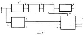
Фиг. 2 представляет блок-схему, показывающую структуру соответствующего варианту осуществления настоящего изобретения устройства распознавания областей отображения изображений. FIG. 2 is a block diagram showing a structure of an image display area recognition apparatus according to an embodiment of the present invention.
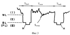
Фиг. 3 представляет диаграмму, используемую для объяснения соответствующего показанному на фиг. 2 варианту осуществления тройного определения. FIG. 3 is a diagram used to explain the corresponding shown in FIG. 2 embodiment of the triple definition.
Фиг. 4 представляет чертеж, используемый для объяснения соответствующего показанному на фиг. 2 варианту осуществления расположения установок. FIG. 4 is a drawing used to explain the corresponding shown in FIG. 2 embodiment of the arrangement of installations.
Фиг. 5A - 5D представляет диаграммы, используемые для объяснения операций соответствующей показанному на фиг. 2 варианту осуществления схемы пикового детектирования. FIG. 5A to 5D are diagrams used to explain operations corresponding to those shown in FIG. 2 of an embodiment of a peak detection circuit.
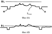
Фиг. 6A и 6B представляют объяснительные диаграммы, изображающие уровни сигнала, получаемые при изменении опорного уровня в показанном на фиг. 2 варианте осуществления изобретения. FIG. 6A and 6B are explanatory diagrams depicting signal levels obtained by changing the reference level in FIG. 2 embodiment of the invention.
Подробное описание предпочтительного варианта осуществления изобретения
Ниже будет приведено описание соответствующего варианту осуществления настоящего изобретения устройства распознавания областей отображения изображений.Detailed Description of a Preferred Embodiment
Below, a description will be made of a device for recognizing image display areas corresponding to an embodiment of the present invention.
Как показано на фиг. 2, соответствующее настоящему изобретению устройство распознавания областей отображения изображений включает в себя входную клемму 1, видеоусилитель 2, схему выделения синхронизирующих сигналов 3, схему фиксации защитного интервала 4, схему пикового детектирования 5 и аналого-цифровой преобразователь 6 и микрокомпьютер (или микроконтроллер) 7. As shown in FIG. 2, an image display area recognition apparatus according to the present invention includes an
На входную клемму 1 поступает показанный на фиг. 3 известный полный видеосигнал SCOMP. На фиг. 3 ссылочные позиции TSCAN, TBACK и H соответствуют периоду строчной развертки, длительности строчного гасящего импульса и сигналу синхронизации строчной развертки соответственно.The
На фиг. 3 пунктирные линии WL, BL и PL представляют уровень белого, уровень черного и уровень защитного интервала соответственно. Уровень черного BL устанавливают на уровне, по существу равном уровню защитного интервала PL. In FIG. The 3 dashed lines WL, BL, and PL represent white level, black level, and guard interval level, respectively. The black level BL is set at a level substantially equal to the level of the guard interval PL.
На фиг. 3 ссылочные позиции I, II, III соответственно представляют область, где уровни яркости видеосигнала выше, чем уровень белого, где уровень яркости видеосигнала лежит между уровнями белого и черного, и область, где уровень яркости видеосигнала ниже, чем уровень черного. In FIG. 3, reference numerals I, II, III respectively represent a region where the brightness levels of the video signal are higher than the white level, where the brightness level of the video signal lies between white and black levels, and a region where the brightness level of the video signal is lower than the black level.
Полный видеосигнал SCOMP, поступающий на входную клемму I, подается на видеоусилитель 2 и схемы разделения синхронизирующих сигналов 3.The full S COMP video signal input to input terminal I is fed to video amplifier 2 and synchronization
Усилитель видеосигнала 2 сформирован из транзистора или аналогичного элемента и усиливает полный видеосигнал SCOMP, выводя его на схему фиксации защитного интервала 4.The video signal amplifier 2 is formed from a transistor or a similar element and amplifies the entire video signal S COMP , bringing it to the fixing circuit of the guard interval 4.
Схема выделения синхронизирующих сигналов 3 выделяет синхронизирующий сигнал строчной развертки H и синхронизирующий сигнал кадровой развертки V из полного видеосигнала SCOMP. Со схемы выделения синхронизирующих сигналов 3 сигналы синхронизации строчной развертки и кадровой развертки H, V подаются на микрокомпьютер 7 и сигнал синхронизации строчной развертки H подается на схему фиксации защитного интервала 4.The synchronization
Схема фиксации защитного интервала 4 имеет функцию устанавливать уровень защитного интервала PL полного видеосигнала SCOMP, поступающего с видеоусилителя 2, на один и тот же уровень при каждом стробировании сигнала синхронизации строчной развертки Н.The guard interval fixing circuit 4 has the function of setting the guard interval level PL of the entire video signal S COMP coming from video amplifier 2 to the same level with each gating of the horizontal synchronization signal N.
Причина данной операции заключается в том, что поскольку составляющая постоянного тока полного видеосигнала SCOMP теряется, когда видеоусилитель 2 усиливает полный видеосигнал SCOMP, уровни защитного интервала PL предотвращены от изменения в зависимости от полных видеосигналов SCOMP, соответствующих яркому изображению и темному изображению. Например, схема фиксации защитного интервала 4 восстанавливает составляющую постоянного тока, устанавливая уровни защитного интервала SCOMP на один и тот же уровень.The reason for this operation is that since the DC component of the full video signal S COMP is lost when video amplifier 2 amplifies the full video signal S COMP , the guard interval levels PL are prevented from changing depending on the full S COMP video signals corresponding to a bright image and a dark image. For example, the latching circuit of the guard interval 4 restores the DC component by setting the guard interval levels S COMP to the same level.
Затем схема фиксации защитного уровня 4 выдает полный видеосигнал SCOMP на схему пикового детектирования 5.Then, the protective level locking circuit 4 provides a complete video signal S COMP to the
На схему пикового детектирования 5 подается полный видеосигнал SCOMP с его постоянным уровнем защитного интервала PL, как описано выше. Как будет описано подробно ниже, управление схемой пикового детектирования 5 осуществляется на основе хронирующего сигнала ST, поступающего с микрокомпьютера 7 и имеющего функцию обнаружения максимального значения (пикового значения) видеосигнала, соответствующего участку обнаружения изображения и выдачи сигнала, указывающего максимальное значение.The
Аналого-цифровой преобразователь 6 преобразует сигнал, указывающий пиковое значение, поступающий со схемы пикового детектирования 5, в цифровой сигнал и выдает цифровой сигнал на микрокомпьютер 7. An analog-to-digital converter 6 converts a signal indicating the peak value coming from the
Микрокомпьютер 7 включает в себя аппаратное оборудование типа центрального процессора (ЦП), запоминающее устройство, хронирующий счетчик или аналогичное ему устройство и программу, предназначенную для выполнения функций, описываемых ниже. The
На входные клеммы CH и CV микрокомпьютера 7 подают синхронизирующий сигнал строчной развертки H и синхронизирующий сигнал кадровой развертки V со схемы выделения синхронизирующих сигналов 3 соответственно. На входную клемму 1 микрокомпьютера 7 подается цифровой сигнал, отображающий пиковое значение, с аналого-цифрового преобразователя 6.At the input terminals C H and C V of the microcomputer 7, a horizontal scanning signal H and a vertical scanning signal V from the synchronization
Микрокомпьютер 7 выдает хронирующий сигнал ST со своей выходной клеммы T на схему пикового детектирования 5.The
Микрокомпьютер 7 устройства распознавания областей отображения изображений, имеющий такую компоновку, выполняет обработку в соответствии с вышеупомянутыми заранее установленными программами, осуществляя таким образом следующие операции:
1) операцию установления областей обнаружения изображений;
2) операцию управления работой схемы пикового детектирования 5;
3) операцию распознавания, отображается ли какое-либо изображение в каждой из упомянутых областей обнаружения изображения;
4) операцию определения, какое из трех значений имеет уровень, полученный от вышеупомянутого распознавания (тройное определение);
5) операцию регулирования уровня черного;
6) операцию сравнения обнаруженных пиковых значений видеосигнала, соответствующих одному и тому же участку определения изображения.The
1) an operation for establishing image detection areas;
2) the operation of controlling the operation of the
3) a recognition operation whether any image is displayed in each of said image detection regions;
4) the operation of determining which of the three values has a level obtained from the aforementioned recognition (triple determination);
5) the operation of adjusting the black level;
6) the operation of comparing the detected peak values of the video signal corresponding to the same portion of the image definition.
1. Установление областей обнаружения изображений
Как показано на фиг. 4, микрокомпьютер 7 устанавливает шестнадцать областей обнаружения изображений 9A-9P на экране изображений 8 телевизионного приемника таким образом, что шестнадцать областей обнаружения изображений 9A-9P перекрывают почти весь экран изображения 8. Микрокомпьютер 7 устанавливает точки выборки в надлежащих точках на линиях строчной развертки в каждой из областей обнаружения изображений 9A-9P. Микрокомпьютер 7 вычисляет координаты точек выборки в величинах времени из сигналов синхронизации строчной развертки и запоминает вычисленные значения времени в запоминающем устройстве.1. Identification of image detection areas
As shown in FIG. 4, the
Хотя в данном варианте осуществления на экране изображения 8 установлены шестнадцать областей обнаружения изображений 9A-9P, настоящее изобретение этим не ограничивается, и достаточно того, что области обнаружения изображений устанавливаются таким образом, чтобы перекрывать почти весь экран изображений 8. Although sixteen
Область обнаружения изображений 9A в виде горизонтальной полоски из числа шестнадцати областей обнаружения изображений 9A-9P установлена в верхней части экрана изображений 8. Известно, что верхняя часть экрана изображений 8 используется только для изображения стандартного размера с форматом телевизионного изображения 4: 3 и становится областью, где изображение не обнаруживается, когда отображается изображение другого размера. The
Известно, что центральная часть экрана изображений 8 используется как для изображения стандартного размера, так и для прямоугольного изображения с размером перспективного видения, размером синемаскопа или ему подобного. Девять небольших областей обнаружения изображений 9B-9J плотно установлены на центральном участке экрана изображений 8, по три в колонках и по три в строках. It is known that the central part of the
Поскольку области обнаружения изображений 9B-9J плотно установлены на центральной части экрана изображений 8, можно распознавать каждый тип размера изображения телевизионной программы, а также можно улучшить точность определения уровня видеосигнала, который соответствует центральной части изображения и значительно изменяется. Since the
Кроме того, в нижней части экрана изображений 8, где отображается наложенный разговор в случае иностранного фильма или чего-то подобного, шесть небольших областей обнаружения изображений 9K-9P, имеющих такие же размеры, как и размеры областей обнаружения изображений 9B-9J, установлены в три колонки и две строки. In addition, at the bottom of the
2. Управление работой схемы пикового детектирования
Как показано на фиг. 5A, микрокомпьютер 7 обеспечивает хронирующие сигналы ST для областей обнаружения изображений 9A -9P (далее обозначаемые соответственно хронирующими сигналами STA-STP) на схему пикового детектирования 5 в точках выборки областей обнаружения изображений 9A-9P.2. Peak detection circuit management
As shown in FIG. 5A, the
В частности, что касается синхронизирующего сигнала кадровой развертки V, микрокомпьютер 7 управляет своим счетчиком синхронизирующего устройства для запуска счета каждый раз, когда на него поступает синхронизирующий сигнал строчной развертки H со схемы выделения синхронизирующих сигналов 3. Когда величина счета счетчика синхронизирующего устройства согласуется с координатой точки выборки каждого из участков обнаружения изображений 9A-9P, микрокомпьютер 7 посылает каждый из хронирующих сигналов STA- STP на схему пикового детектирования 5, как показано на фиг. 5A. Когда величина счета счетчика синхронизирующего устройства не согласуется с какой-либо из координат установленных точек выборки на линиях строчной развертки на участках обнаружения изображений 9A-9P, микрокомпьютер 7 останавливает подачу какого-либо из хронирующих сигналов STA-STP на схему пикового детектирования 5.In particular, with regard to the vertical scanning signal V, the
Схема пикового детектирования 5 включает в себя регистр, предназначенный для временного запоминания обнаруженного значения напряжения в точке выборки. В ответ на каждый из хронирующих сигналов STA-STP c микрокомпьютера 7 схема пикового детектирования 5 обнаруживает величину напряжения в точке выборки и временно запоминает ее в регистре. Схема пикового детектирования 5 сравнивает обнаруженное значение напряжения в данной точке выборки со значением напряжения, обнаруженным в предшествующей выборочной точке и временно запомненном в регистре, и на основании результата сравнения запоминает в регистре большее значение напряжения. Таким образом, регистр может запоминать максимальное значение из значений напряжения, обнаруживаемых во всех выборочных точках в каждом из участков отображения изображения 9A-9P. Схема пикового детектирования 5 выдает сигнал, показывающий это максимальное значение, на аналого-цифровой преобразователь 7.The
На фиг. 5C показан простой пример изображения, получаемого, когда изображение иностранного кинофильма размера синемаскоп для стандартного телевизионного приемника отображают в таком виде, как показано на экране изображений 8 широкоэкранного телевизионного приемника. Размер изображения не увеличен в направлении высоты кадра и, следовательно, отображаемое изображение не увеличивается в значительной степени в направлении высоты кадра. In FIG. 5C shows a simple example of an image obtained when an image of a foreign cinemascope movie for a standard television receiver is displayed as shown on the
На фиг. 5B показаны уровни яркости видеосигнала, соответствующие участкам изображения, отображаемого на экране изображений 8. Конкретно, верхняя часть 8a экрана изображений 8 является участком, на котором изображение не отображается. В центре экрана изображений 8b отображен слегка темный участок фона. В центре слегка затемненного участка фона 8b отображен эллиптический участок 8b. В эллиптическом участке 8c отображен более яркий прямоугольный участок 8d. Участок наложенного разговора 8e ярко отображен на нижнем темном участке экрана изображений 8e. In FIG. 5B shows video brightness levels corresponding to portions of an image displayed on the
Когда такое изображение отображено на экране изображений 8, как показано на фиг. 5D, схема пикового детектирования 5 выдает выходные сигналы S5A-S5P, представляющие показанные на фиг. 5B уровни яркости, на основании хронирующих сигналов STA-STP, показанных на фиг. 5A. Выходные сигналы S5A-S5P соответствуют областям отображения изображений 9A-9P соответственно.When such an image is displayed on the
В частности, в данном случае, поскольку верхний участок 8a является участком, на котором изображение не отображается, схема пикового детектирования 5 не выдает выходной сигнал S5A на основании показанного на фиг. 5A хронирующего сигнала STA. На основании показанных на фиг. 5A хронирующих сигналов STB-STD схема пикового детектирования 5 выдает выходные сигналы S5B-S5D, соответствующие слегка затемненному фоновому участку 8b и имеющие по существу средние значения уровней яркости между уровнем черного и уровнем белого. На основании хронирующих сигналов STE-STG и хронирующих сигналов STH-STJ схема пикового детектирования 5 соответственно выдает выходные сигналы S5E-S5G и выходные сигналы S5H-S5J, которые соответствуют яркому эллиптическому участку 8c и более яркому прямоугольнику 8d и имеют уровни яркости, по существу близкие к уровню белого. На основании хронирующих сигналов STK-STM и хронирующих сигналов STN-STP схема пикового детектирования 5 соответственно выдает выходные сигналы S5K-S5M и выходные сигналы S5N-S5P, соответствующие наложенному разговору 8e и имеющие уровни яркости на уровне белого. Полученные таким образом сигналы, отображающие уровни яркости, используются в качестве данных, предназначенных для распознавания наличия или отсутствия изображения.In particular, in this case, since the
3. Распознавание наличия или отсутствия изображения
Микрокомпьютер 7 запоминает множество опорных уровней в запоминающем устройстве.3. Recognition of the presence or absence of an image
The
Микрокомпьютер 7 сравнивает цифровой сигнал, выходящий из аналого-цифрового преобразователя 6, с опорными уровнями для распознавания уровней яркости видеосигналов, соответствующих областям отображения изображения 9A-9P. На основании результатов распознавания микрокомпьютер 7 определяет, отображено ли какое-либо изображение на каждом из участков отображения изображений 9A-9P. Основываясь на результатах определения, микрокомпьютер 7 распознает тип размера изображения отображаемого изображения в соответствии с заранее заданным алгоритмом распознавания размеров изображений, например, выбирая при этом режим отображения. Когда микрокомпьютер 7 определяет, отображено ли какое-нибудь изображение на участке, соответствующем участку 8e накладываемого разговора, определяется также уровень белого, и микрокомпьютер 7 использует не только уровень черного, но также и уровень белого для вышеупомянутого распознавания, что улучшает надежность распознавания. The
4. Тройное определение
Когда микрокомпьютер 7 распознает наличие или отсутствие изображения при вышеупомянутом определении наличия или отсутствия изображения, микрокомпьютер 7 осуществляет так называемое тройное определение, то есть он использует два разных опорных значения WL, BL опорных уровней, как показано на фиг. 3, с целью определения, в которую область из областей выше уровня белого, ниже уровня черного или между уровнями белого и черного попадает уровень видеосигнала. При использовании в качестве опорного уровня только уровня черного, если уровень черного выше, то микрокомпьютер 7 ошибочно определяет область, где отображено какое-нибудь изображение, как область, где изображение не отображается. Таким образом, данное тройное определение может предотвратить такое ошибочное определение. В соответствии с этим это определение может улучшить точность определения наличия или отсутствия какого-либо отображаемого изображения.4. Triple definition
When the
5. Регулирование уровня черного
Когда микрокомпьютер 7 снижает опорное значение уровня черного, запомненного в запоминающем устройстве, подчиняясь некоторым условиям, можно регулировать видеосигнал, все уровни яркости которого определены как уровни более низкие, чем уровень черного, как показано на фиг. 6A, и, как показано на фиг. 6B, можно найти уровень яркости выше, чем уровень черного из показанного на фиг. 6A видеосигнала. Такое регулирование можно легко реализовать только с помощью изменения содержимого запоминающего устройства микрокомпьютера 7.5. Black Level Adjustment
When the
6. Сравнение обнаруживаемых значений, полученных из видеосигнала, соответствующего одному и тому же участку определения изображения
Микрокомпьютер 7 запоминает пиковые значения, определяемые из видеосигнала, соответствующего одному и тому же участку обнаружения изображения в запоминающем устройстве в заранее установленное время, запоминая при этом изменение видеосигнала, соответствующего области обнаружения изображения. Следовательно, можно обнаружить изображение, уровень яркости которого существенно не меняется при сравнении пиковых значений, полученных в заранее установленный момент времени.6. Comparison of detectable values obtained from a video signal corresponding to the same image detection portion
The
Хотя в данном варианте осуществления количество, позиции и размеры участков обнаружения изображения 9A-9P установлены такими, как показано на фиг. 4, настоящее изобретение этим не ограничено, и количество, позиции и размеры таких участков можно легко изменять в соответствии с программой, запомненной в микрокомпьютере 7. Although in this embodiment, the number, positions and sizes of
В устройстве распознавания областей отображения изображений в соответствии с данным вариантом осуществления изобретения можно обычно использовать видеоусилитель 2, схему выделения синхронизирующих сигналов 3 и схему фиксации защитного интервала 4 телевизионного приемника, в котором обеспечено устройство распознавания участков отображения изображений. In a device for recognizing image display areas in accordance with this embodiment of the invention, a video amplifier 2, a synchronization
Как было описано выше, при надлежащем объединении тройного определения, регулировании уровня черного, временной записи пиковых значений и так далее можно очень точно распознавать, является ли область обнаружения изображения областью, где изображение не отображается, или областью, где отображено какое-то изображение. As described above, with the proper combination of the triple determination, black level adjustment, temporary recording of peak values, and so on, it is possible to very accurately recognize whether the image detection area is an area where the image is not displayed, or an area where some image is displayed.
Как было описано выше, согласно соответствующему настоящему изобретению устройству распознавания областей отображения изображений, поскольку обнаруживается относительно уровня черного и уровня белого, отображено ли какое-нибудь изображение в каждой из областей обнаружения изображений 9A-9P, расположенных таким образом, чтобы перекрывать почти весь экран изображений 8 телевизионного приемника, можно осуществлять тройное определение и определять, что в области обнаружения изображений отображено какое-то изображение, но в ней не отображен наложенный разговор. As described above, according to the image display area recognition apparatus according to the present invention, since it is detected with respect to the black level and white level, is there any image displayed in each of the
Поскольку опорное значение уровня черного можно надлежащим образом устанавливать и изменять, то можно, необязательно, понизить опорное значение уровня черного, когда распознают уровень видеосигнала, например, имеющего низкий уровень черного. Это ведет к повышенной чувствительности уровня черного. Since the black level reference value can be appropriately set and changed, it is possible to optionally lower the black level reference value when the level of a video signal, for example having a low black level, is recognized. This leads to increased black level sensitivity.
Кроме того, поскольку пиковое значение сравнивается с предыдущим пиковым значением и результат сравнения запоминается на заранее определенное время, можно простым средством обнаруживать видеосигнал, уровень яркости которого существенно не меняется. In addition, since the peak value is compared with the previous peak value and the comparison result is stored for a predetermined time, it is possible by a simple means to detect a video signal whose brightness level does not change significantly.
Имея описанный предпочтительный вариант осуществления настоящего изобретения со ссылкой на прилагаемые чертежи, следует понимать, что настоящее изобретение не ограничивается вышеупомянутым вариантом осуществления, и что специалисты в данной области техники могут выполнить различные изменения и модификации, не выходя при этом за рамки сущности и объема притязания настоящего изобретения, определяемые прилагаемой формулой изобретения. Having described the preferred embodiment of the present invention with reference to the accompanying drawings, it should be understood that the present invention is not limited to the aforementioned embodiment, and that those skilled in the art can make various changes and modifications without departing from the essence and scope of the present invention. inventions defined by the attached claims.
Claims (7)
Applications Claiming Priority (2)
| Application Number | Priority Date | Filing Date | Title |
|---|---|---|---|
| JP15319395A JP3508119B2 (en) | 1995-06-20 | 1995-06-20 | Screen display area determination device |
| JPP07-153193 | 1995-06-20 |
Publications (2)
| Publication Number | Publication Date |
|---|---|
| RU96111956A RU96111956A (en) | 1998-09-27 |
| RU2172016C2 true RU2172016C2 (en) | 2001-08-10 |
Family
ID=15557085
Family Applications (1)
| Application Number | Title | Priority Date | Filing Date |
|---|---|---|---|
| RU96111956/09A RU2172016C2 (en) | 1995-06-20 | 1996-06-19 | Image display region identifying device |
Country Status (8)
| Country | Link |
|---|---|
| US (1) | US5990971A (en) |
| JP (1) | JP3508119B2 (en) |
| KR (1) | KR970004909A (en) |
| CN (1) | CN1082311C (en) |
| MY (1) | MY116655A (en) |
| RU (1) | RU2172016C2 (en) |
| SG (1) | SG67949A1 (en) |
| TW (1) | TW376631B (en) |
Families Citing this family (6)
| Publication number | Priority date | Publication date | Assignee | Title |
|---|---|---|---|---|
| FR2793375A1 (en) * | 1999-05-06 | 2000-11-10 | Thomson Multimedia Sa | METHOD FOR DETECTING BLACK BANDS IN A VIDEO IMAGE |
| JP4920834B2 (en) * | 2000-06-26 | 2012-04-18 | キヤノン株式会社 | Image display device and driving method of image display device |
| US7339627B2 (en) * | 2003-10-30 | 2008-03-04 | Broadcom Corporation | Method and system for automatic detection and display of aspect ratio |
| JP3711994B2 (en) * | 2003-12-03 | 2005-11-02 | セイコーエプソン株式会社 | Video signal discrimination apparatus and video signal discrimination method |
| US7119847B2 (en) * | 2003-12-17 | 2006-10-10 | Texas Instruments Incorporated | Method for identifying format of a received video signal |
| JP5573292B2 (en) * | 2010-03-30 | 2014-08-20 | パナソニック株式会社 | Video source switching device |
Family Cites Families (13)
| Publication number | Priority date | Publication date | Assignee | Title |
|---|---|---|---|---|
| US3947631A (en) * | 1974-02-27 | 1976-03-30 | Gte Sylvania Incorporated | Automatic video signal control circuit |
| US4622577A (en) * | 1984-02-03 | 1986-11-11 | Rca Corporation | Decoder for extracting a 4:3 aspect ratio signal from a high definition television signal |
| US5486871A (en) * | 1990-06-01 | 1996-01-23 | Thomson Consumer Electronics, Inc. | Automatic letterbox detection |
| US5249049A (en) * | 1990-06-01 | 1993-09-28 | Thomson Consumer Electronics, Inc. | Managing letterbox displays |
| FR2664779B1 (en) * | 1990-07-13 | 1993-06-11 | Europ Rech Electr Lab | PROCESS FOR PROCESSING A VIDEO SIGNAL. |
| US5309234A (en) * | 1991-05-29 | 1994-05-03 | Thomson Consumer Electronics | Adaptive letterbox detector |
| JPH04365278A (en) * | 1991-06-13 | 1992-12-17 | Matsushita Electric Ind Co Ltd | Multi-screen display circuit |
| JP3211969B2 (en) * | 1991-06-27 | 2001-09-25 | ソニー株式会社 | Display device |
| JP3240697B2 (en) * | 1992-08-11 | 2001-12-17 | 松下電器産業株式会社 | Video magnifier |
| KR970008379B1 (en) * | 1993-09-08 | 1997-05-23 | Samsung Electronics Co Ltd | Method and apparatus for decreasing side blank of wide screen |
| TW307971B (en) * | 1994-03-31 | 1997-06-11 | Matsushita Electric Ind Co Ltd | |
| WO1995030303A1 (en) * | 1994-04-28 | 1995-11-09 | Kabushiki Kaisha Toshiba | Device for detecting image of letter box |
| TW344931B (en) * | 1994-12-08 | 1998-11-11 | Matsushita Electric Ind Co Ltd | Average luminance level detection apparatus and aspect ratio auto-discrimination apparatus for a television signal using the same |
-
1995
- 1995-06-20 JP JP15319395A patent/JP3508119B2/en not_active Expired - Fee Related
-
1996
- 1996-06-15 TW TW085107218A patent/TW376631B/en active
- 1996-06-19 SG SG1996010101A patent/SG67949A1/en unknown
- 1996-06-19 US US08/665,880 patent/US5990971A/en not_active Expired - Fee Related
- 1996-06-19 KR KR1019960022193A patent/KR970004909A/en not_active Application Discontinuation
- 1996-06-19 MY MYPI96002462A patent/MY116655A/en unknown
- 1996-06-19 RU RU96111956/09A patent/RU2172016C2/en not_active IP Right Cessation
- 1996-06-20 CN CN96110452A patent/CN1082311C/en not_active Expired - Fee Related
Non-Patent Citations (1)
| Title |
|---|
| US 424072 * |
Also Published As
| Publication number | Publication date |
|---|---|
| TW376631B (en) | 1999-12-11 |
| SG67949A1 (en) | 1999-10-19 |
| US5990971A (en) | 1999-11-23 |
| MY116655A (en) | 2004-03-31 |
| KR970004909A (en) | 1997-01-29 |
| CN1146116A (en) | 1997-03-26 |
| JP3508119B2 (en) | 2004-03-22 |
| CN1082311C (en) | 2002-04-03 |
| JPH099170A (en) | 1997-01-10 |
Similar Documents
| Publication | Publication Date | Title |
|---|---|---|
| KR100190494B1 (en) | Video type discrimination apparatus, and aspect ratio auto-discrimination apparatus and television receiver using the same | |
| EP0677959B1 (en) | Picture information detecting apparatus for a video signal | |
| EP0913993A1 (en) | Method and apparatus for automatic format detection in digital video picture | |
| TW389018B (en) | Aspect ratio discrimination appartus and image display apparatus ncludingthe same | |
| US5267035A (en) | Motion detection for video including that obtained from film | |
| KR100196554B1 (en) | Managing letterbox signals with logos | |
| US6313881B1 (en) | Signal processing for a picture signal | |
| KR100196553B1 (en) | Managing letter box signals with logos and closed captions | |
| JPH08500477A (en) | Television receiver | |
| KR920005602A (en) | TV automatic control circuit | |
| RU2172016C2 (en) | Image display region identifying device | |
| US4677482A (en) | Dual mode progressive scan system with automatic mode switching by image analysis | |
| US5686970A (en) | Average luminance level detection apparatus and aspect ratio auto-discrimination apparatus for a television signal using the same | |
| KR940003050B1 (en) | Television receiver responsive to plural video signals | |
| US5220423A (en) | Apparatus for controlling display of an image on a large aspect ratio television screen | |
| JP3232950B2 (en) | Video type identification device, automatic aspect ratio identification device and television receiver using the same | |
| RU96111956A (en) | DEVICE FOR RECOGNITION OF IMAGE AREAS | |
| EP0913994B1 (en) | Method and apparatus for automatic format detection in digital video pictures | |
| JP3541529B2 (en) | Automatic Aspect Ratio Identification System for Television Signals | |
| JP2002077768A (en) | Image signal processor | |
| US5844624A (en) | Television receiver | |
| JP3242831B2 (en) | Screen size determination device | |
| JP2737601B2 (en) | Character position shift circuit for video signal | |
| KR970078503A (en) | Sub screen position automatic moving device for watching main screen caption | |
| JPH07298200A (en) | Letter box screen detector |
Legal Events
| Date | Code | Title | Description |
|---|---|---|---|
| MM4A | The patent is invalid due to non-payment of fees |
Effective date: 20020620 |