RU2154309C2 - Method and device for controlling access to data recording disk - Google Patents
Method and device for controlling access to data recording disk Download PDFInfo
- Publication number
- RU2154309C2 RU2154309C2 RU97112873/28A RU97112873A RU2154309C2 RU 2154309 C2 RU2154309 C2 RU 2154309C2 RU 97112873/28 A RU97112873/28 A RU 97112873/28A RU 97112873 A RU97112873 A RU 97112873A RU 2154309 C2 RU2154309 C2 RU 2154309C2
- Authority
- RU
- Russia
- Prior art keywords
- disk
- data
- recording data
- head
- recording
- Prior art date
Links
Images


Classifications
-
- G—PHYSICS
- G06—COMPUTING; CALCULATING OR COUNTING
- G06F—ELECTRIC DIGITAL DATA PROCESSING
- G06F3/00—Input arrangements for transferring data to be processed into a form capable of being handled by the computer; Output arrangements for transferring data from processing unit to output unit, e.g. interface arrangements
- G06F3/06—Digital input from, or digital output to, record carriers, e.g. RAID, emulated record carriers or networked record carriers
- G06F3/0601—Interfaces specially adapted for storage systems
- G06F3/0602—Interfaces specially adapted for storage systems specifically adapted to achieve a particular effect
- G06F3/061—Improving I/O performance
- G06F3/0613—Improving I/O performance in relation to throughput
-
- G—PHYSICS
- G06—COMPUTING; CALCULATING OR COUNTING
- G06F—ELECTRIC DIGITAL DATA PROCESSING
- G06F3/00—Input arrangements for transferring data to be processed into a form capable of being handled by the computer; Output arrangements for transferring data from processing unit to output unit, e.g. interface arrangements
- G06F3/06—Digital input from, or digital output to, record carriers, e.g. RAID, emulated record carriers or networked record carriers
- G06F3/0601—Interfaces specially adapted for storage systems
- G06F3/0628—Interfaces specially adapted for storage systems making use of a particular technique
- G06F3/0629—Configuration or reconfiguration of storage systems
- G06F3/0634—Configuration or reconfiguration of storage systems by changing the state or mode of one or more devices
-
- G—PHYSICS
- G06—COMPUTING; CALCULATING OR COUNTING
- G06F—ELECTRIC DIGITAL DATA PROCESSING
- G06F3/00—Input arrangements for transferring data to be processed into a form capable of being handled by the computer; Output arrangements for transferring data from processing unit to output unit, e.g. interface arrangements
- G06F3/06—Digital input from, or digital output to, record carriers, e.g. RAID, emulated record carriers or networked record carriers
- G06F3/0601—Interfaces specially adapted for storage systems
- G06F3/0628—Interfaces specially adapted for storage systems making use of a particular technique
- G06F3/0655—Vertical data movement, i.e. input-output transfer; data movement between one or more hosts and one or more storage devices
- G06F3/0659—Command handling arrangements, e.g. command buffers, queues, command scheduling
-
- G—PHYSICS
- G06—COMPUTING; CALCULATING OR COUNTING
- G06F—ELECTRIC DIGITAL DATA PROCESSING
- G06F3/00—Input arrangements for transferring data to be processed into a form capable of being handled by the computer; Output arrangements for transferring data from processing unit to output unit, e.g. interface arrangements
- G06F3/06—Digital input from, or digital output to, record carriers, e.g. RAID, emulated record carriers or networked record carriers
- G06F3/0601—Interfaces specially adapted for storage systems
- G06F3/0668—Interfaces specially adapted for storage systems adopting a particular infrastructure
- G06F3/0671—In-line storage system
- G06F3/0673—Single storage device
- G06F3/0674—Disk device
- G06F3/0677—Optical disk device, e.g. CD-ROM, DVD
-
- G—PHYSICS
- G11—INFORMATION STORAGE
- G11B—INFORMATION STORAGE BASED ON RELATIVE MOVEMENT BETWEEN RECORD CARRIER AND TRANSDUCER
- G11B11/00—Recording on or reproducing from the same record carrier wherein for these two operations the methods are covered by different main groups of groups G11B3/00 - G11B7/00 or by different subgroups of group G11B9/00; Record carriers therefor
- G11B11/10—Recording on or reproducing from the same record carrier wherein for these two operations the methods are covered by different main groups of groups G11B3/00 - G11B7/00 or by different subgroups of group G11B9/00; Record carriers therefor using recording by magnetic means or other means for magnetisation or demagnetisation of a record carrier, e.g. light induced spin magnetisation; Demagnetisation by thermal or stress means in the presence or not of an orienting magnetic field
- G11B11/105—Recording on or reproducing from the same record carrier wherein for these two operations the methods are covered by different main groups of groups G11B3/00 - G11B7/00 or by different subgroups of group G11B9/00; Record carriers therefor using recording by magnetic means or other means for magnetisation or demagnetisation of a record carrier, e.g. light induced spin magnetisation; Demagnetisation by thermal or stress means in the presence or not of an orienting magnetic field using a beam of light or a magnetic field for recording by change of magnetisation and a beam of light for reproducing, i.e. magneto-optical, e.g. light-induced thermomagnetic recording, spin magnetisation recording, Kerr or Faraday effect reproducing
- G11B11/10595—Control of operating function
-
- G—PHYSICS
- G11—INFORMATION STORAGE
- G11B—INFORMATION STORAGE BASED ON RELATIVE MOVEMENT BETWEEN RECORD CARRIER AND TRANSDUCER
- G11B21/00—Head arrangements not specific to the method of recording or reproducing
- G11B21/02—Driving or moving of heads
- G11B21/08—Track changing or selecting during transducing operation
- G11B21/081—Access to indexed tracks or parts of continuous track
- G11B21/083—Access to indexed tracks or parts of continuous track on discs
-
- G—PHYSICS
- G11—INFORMATION STORAGE
- G11B—INFORMATION STORAGE BASED ON RELATIVE MOVEMENT BETWEEN RECORD CARRIER AND TRANSDUCER
- G11B27/00—Editing; Indexing; Addressing; Timing or synchronising; Monitoring; Measuring tape travel
- G11B27/10—Indexing; Addressing; Timing or synchronising; Measuring tape travel
- G11B27/102—Programmed access in sequence to addressed parts of tracks of operating record carriers
- G11B27/105—Programmed access in sequence to addressed parts of tracks of operating record carriers of operating discs
-
- G—PHYSICS
- G11—INFORMATION STORAGE
- G11B—INFORMATION STORAGE BASED ON RELATIVE MOVEMENT BETWEEN RECORD CARRIER AND TRANSDUCER
- G11B5/00—Recording by magnetisation or demagnetisation of a record carrier; Reproducing by magnetic means; Record carriers therefor
- G11B5/48—Disposition or mounting of heads or head supports relative to record carriers ; arrangements of heads, e.g. for scanning the record carrier to increase the relative speed
- G11B5/54—Disposition or mounting of heads or head supports relative to record carriers ; arrangements of heads, e.g. for scanning the record carrier to increase the relative speed with provision for moving the head into or out of its operative position or across tracks
- G11B5/55—Track change, selection or acquisition by displacement of the head
- G11B5/5521—Track change, selection or acquisition by displacement of the head across disk tracks
- G11B5/5526—Control therefor; circuits, track configurations or relative disposition of servo-information transducers and servo-information tracks for control thereof
- G11B5/553—Details
- G11B5/5547—"Seek" control and circuits therefor
-
- G—PHYSICS
- G06—COMPUTING; CALCULATING OR COUNTING
- G06F—ELECTRIC DIGITAL DATA PROCESSING
- G06F3/00—Input arrangements for transferring data to be processed into a form capable of being handled by the computer; Output arrangements for transferring data from processing unit to output unit, e.g. interface arrangements
- G06F3/06—Digital input from, or digital output to, record carriers, e.g. RAID, emulated record carriers or networked record carriers
- G06F3/0601—Interfaces specially adapted for storage systems
- G06F3/0628—Interfaces specially adapted for storage systems making use of a particular technique
- G06F3/0653—Monitoring storage devices or systems
-
- G—PHYSICS
- G11—INFORMATION STORAGE
- G11B—INFORMATION STORAGE BASED ON RELATIVE MOVEMENT BETWEEN RECORD CARRIER AND TRANSDUCER
- G11B2220/00—Record carriers by type
- G11B2220/20—Disc-shaped record carriers
-
- G—PHYSICS
- G11—INFORMATION STORAGE
- G11B—INFORMATION STORAGE BASED ON RELATIVE MOVEMENT BETWEEN RECORD CARRIER AND TRANSDUCER
- G11B2220/00—Record carriers by type
- G11B2220/20—Disc-shaped record carriers
- G11B2220/25—Disc-shaped record carriers characterised in that the disc is based on a specific recording technology
- G11B2220/2508—Magnetic discs
- G11B2220/2516—Hard disks
Abstract
Description
Настоящее изобретение относится к способу управления доступом к диску для записи данных, требующему высокой скорости передачи и доступа к отдельным участкам на диске (случайного доступа), и устройству для осуществления способа. The present invention relates to a method of controlling access to a disk for recording data requiring a high transmission speed and access to individual sections of the disk (random access), and a device for implementing the method.
Предшествующий уровень техники
С увеличением быстродействия компьютеров все более важными становятся устройства памяти на дисках, которые дают возможность осуществить быстрый случайный доступ. В последние годы, особенно в технологии для мультимедиа, основное внимание уделяется в первую очередь выборке с высокой скоростью движущихся изображений и аудиоданных, хранимых на диске в виде цифровых данных, и с участков на диске, отделенных один от другого. А именно, требуются высокая скорость передачи и возможность обработки в реальном времени для хранения мультимедийных данных, таких как движущиеся изображения и аудиоданные. Высокая скорость передачи, естественно, становится необходимой при обработке большого количества движущихся изображений и аудиоданных.State of the art
With the increasing speed of computers, memory devices on disks become more important, which make it possible to carry out quick random access. In recent years, especially in technology for multimedia, the main focus is primarily on high-speed sampling of moving images and audio data stored on the disk in the form of digital data, and from sections on the disk separated from one another. Namely, high transmission speed and real-time processing capability for storing multimedia data such as moving images and audio data is required. High speed transmission, of course, becomes necessary when processing a large number of moving images and audio data.
Кроме того, свойство реального времени требует, чтобы верхний предел времени обработки не был превышен. Например, движение становится прерывистым, если в движущемся изображении не отображается 30 кадров в секунду с постоянными интервалами. In addition, the real-time property requires that the upper limit of processing time not be exceeded. For example, motion becomes intermittent if 30 frames per second are not displayed in the moving image at regular intervals.
Далее, если не обеспечивается поддержание характеристик диска и имеется недостаточное количество аудиоданных, звук прерывается и генерируется неприятный шум. Таким образом, если мультимедийные данные не подготовлены и не используются в соответственно заданное для них время, ценность информации резко падает. Соответственно, в устройствах памяти для мультимедиа важно, чтобы гарантировался верхний предел, то есть чтобы обработка была выполнена за это время даже в наихудшем случае. В противном случае, даже если удовлетворяются технические условия в смысле средней эффективности, возможно, что данные будут слишком запаздывать в некоторые периоды времени. Обеспечение максимального значения времени обработки относится к так называемому свойству реального времени и является обязательной функцией в области мультимедиа. Further, if the characteristics of the disc are not maintained and there is insufficient audio data, the sound is interrupted and an unpleasant noise is generated. Thus, if multimedia data is not prepared and is not used at the appropriate time for them, the value of the information drops sharply. Accordingly, in multimedia memory devices, it is important that the upper limit is guaranteed, that is, that processing is performed during this time even in the worst case. Otherwise, even if the technical conditions in the sense of average efficiency are satisfied, it is possible that the data will be too late in some periods of time. Ensuring the maximum value of processing time refers to the so-called real-time property and is a mandatory function in the field of multimedia.
В устройствах хранении информации для компьютеров увеличение средней эффективности является первостепенной задачей. Наихудшее значение не всегда поддерживалось низким, т. е. существовал большой разброс в характеристике времени обработки в устройствах хранения данных. Это положение противоречит требованиям, предъявляемым к устройствам хранения данных для мультимедиа. In computer storage devices, increasing average efficiency is a priority. The worst value was not always kept low, i.e. there was a large variation in the characteristic of processing time in data storage devices. This provision contradicts the requirements for multimedia storage devices.
К тому же, в основных областях применения мультимедиа необходимо обеспечивать последовательный доступ к данным на физически разделенных участках (случайный доступ) с высокой скоростью. Напри мер, система типа "видео-по-требованию" (VOD) позволяет большому количеству зрителей вызывать и просматривать желаемые программы в удобное для них время. Для реализации такого режима необходимо параллельно обрабатывать запросы от многих зрителей и быстро подготавливать данные программ, которые зрители просматривают в данное время. По этой причине становится необходимым с высокой скоростью отслеживать источники видеосюжетов и т.д., хранимых во множестве местоположений на диске. In addition, in the main areas of multimedia applications, it is necessary to provide consistent access to data in physically separated areas (random access) with high speed. For example, a video-on-demand (VOD) system allows a large number of viewers to call and watch their desired programs at a convenient time for them. To implement such a regime, it is necessary to simultaneously process requests from many viewers and quickly prepare program data that viewers are currently viewing. For this reason, it becomes necessary to quickly track sources of videos, etc., stored in a variety of locations on the disk.
В последние годы видеопрограммы и кинофильмы выпускаются с использованием не магнитных лент и пленок, а дисков. На магнитной ленте при вставке сцены продолжительностью в несколько секунд в положение, близкое к началу программы продолжительностью, например, один час, для предотвращения наложения записи необходимо сдвинуть к концу все видеоданные после этого положения вставки и поэтому перезаписать программу. В отличие от высокоскоростного воспроизведения аналоговых магнитных лент аудиокассет такая перезапись видеопрограмм требует затрат времени примерно одной программы, т.е. эффективность мала. С использованием диска, однако, так как возможен случайный доступ, имеется возможность разместить вставляемую часть в другое место на диске, перейти в это положение и выбрать вставленные данные во время воспроизведения, а затем возвратиться в исходную позицию и продолжить воспроизведение видеоданных. Известен способ, при котором каждую сцену (отрезок) программы размещают на различных участках диска и отслеживают их с высокой скоростью во время воспроизведения так, что кажется, что воспроизводится одна лента. Таким образом, возможно переключать сцены и изменять продолжительность воспроизведения, просто изменяя порядок отслеживания данных на диске. Эффективность такого редактирования чрезвычайно высока. Такой способ определяется как нелинейное редактирование. Отметим, что в этом случае также необходимо отслеживать физически разделенные участки на диске с высокой скоростью. In recent years, video programs and films have been released using discs rather than magnetic tapes and films. On a magnetic tape, when inserting a scene lasting several seconds to a position close to the beginning of the program lasting, for example, one hour, to prevent overdubbing, it is necessary to shift to the end all the video data after this insertion position and therefore overwrite the program. Unlike high-speed playback of analog magnetic tapes of audio tapes, such dubbing of video programs requires a time investment of approximately one program, i.e. efficiency is low. Using the disc, however, since random access is possible, it is possible to place the inserted part in another place on the disc, go to this position and select the inserted data during playback, and then return to the original position and continue playing the video data. There is a method in which each scene (segment) of the program is placed on different parts of the disc and tracked with high speed during playback so that it seems that one tape is being played. Thus, it is possible to switch scenes and change the duration of playback, simply changing the order of tracking data on the disk. The effectiveness of such editing is extremely high. This method is defined as non-linear editing. Note that in this case, it is also necessary to track physically separated sections of the disk with high speed.
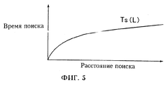
Как видно в этих примерах, в областях применения мультимедиа чрезвычайно важно выбирать данные с высокой скоростью, в то же время отслеживая разобщенные данные на диске (это относится к так называемому случайному доступу), но для перемещения к разобщенным участкам требуется время для перемещения головки к требуемому цилиндру (группе дорожек дискового пакета), которое называется временем поиска, и время ожидания, когда диск повернется до положения, при котором в цилиндре появятся данные начала, которое называется временем задержки вращения. Эти интервалы времени относятся к так называемым накладным расходам на обеспечение доступа. Чем больше это время по сравнению с временем реальной выборки данных, тем большее время требуется для передачи данных с диска и поэтому тем ниже эффективность. As can be seen in these examples, in the fields of multimedia applications it is extremely important to select data at high speed, while at the same time tracking the fragmented data on the disk (this refers to the so-called random access), but it takes time to move to the disconnected sections to move the head to the required a cylinder (a group of tracks of a disk package), which is called the search time, and the wait time when the disk is rotated to the position at which the start data appears in the cylinder, which is called the delay time is rotated i. These time intervals refer to the so-called access overhead. The longer this time compared with the actual data sampling time, the longer it takes to transfer data from disk and therefore the lower the efficiency.
Принимая время поиска для диска равным Ts и время задержки вращения равным Tr, накладные расходы на доступ к диску становятся равными Ts + Tr. Когда головка диска позиционирована в области данных и время реального доступа к данным равно Tt, эффективность по сравнению со случаем отсутствия перехода головки в конкретное положение становится низкой, как следует из уравнения (1):
Tt/(Tt+Ts+Tr)
А именно, по сравнению со случаем, когда данные на диске последовательно выбираются от начала до конца, в случае, когда выполняется случайный доступ при отслеживании данных в отдельных участках, необходимо иметь в виду, что эффективность снижается на эту величину. Соответственно, задачей, связанной с дисками для мультимедиа, является предотвращение снижения эффективности в режиме случайного доступа при одновременном сохранении свойства реального времени (для определения верхнего предела времени обработки и обеспечения работы с интервалом времени, равным или меньшим этому верхнему пределу).Assuming the search time for the disk to be Ts and the rotation delay time to Tr, the overhead of accessing the disk becomes Ts + Tr. When the disk head is positioned in the data region and the real data access time is Tt, the efficiency compared to the case when there is no transition of the head to a specific position becomes low, as follows from equation (1):
Tt / (Tt + Ts + Tr)
Namely, in comparison with the case when data on the disk is sequentially selected from the beginning to the end, in the case when random access is performed while tracking data in individual sections, it must be borne in mind that the efficiency is reduced by this value. Accordingly, the task associated with multimedia disks is to prevent a decrease in efficiency in random access mode while preserving the real-time property (to determine the upper limit of the processing time and ensure operation with a time interval equal to or less than this upper limit).
В последние годы были проведены исследования, связанные со способом обеспечения свойства реального времени при доступе к диску. Например, в работе D. Anderson, Y. Osawa and R. Govindan, "A File System for Continuous Media", ASM Transactions on Computer Systems, Vol. 10, N. 4, стр. 311-337, 1992 была сделана попытка увеличить эффективность системы посредством оптимизации соотношения между объемом буферной памяти для временного хранения данных, считанных с диска, и количеством данных, которые должны быть считаны во время одной выборки. In recent years, studies have been conducted related to the method of providing real-time properties when accessing the disk. For example, D. Anderson, Y. Osawa and R. Govindan, "A File System for Continuous Media", ASM Transactions on Computer Systems, Vol. 10, N. 4, pp. 311-337, 1992, an attempt was made to increase the efficiency of the system by optimizing the ratio between the amount of buffer memory for temporary storage of data read from disk and the amount of data that should be read during one sample.
При рассмотрении накладных расходов на выборку с диска для облегчения анализа предполагается, что возможны наихудшие значения для времени поиска и времени задержки вращения в каждом случайном доступе. А именно, время поиска от крайней внутренней окружности до наиболее крайней окружности принимается в качестве времени поиска, а время ожидания для одного полного оборота принимается в качестве времени задержки вращения. Конечно, если делается такое предположение, то оценка наихудшего значения времени обработки является наиболее надежной, но такая операция проводится в действительности не каждый раз, и поэтому оценка для наихудшего значения становится очень низкой по сравнению с эффективностью, которая может быть достигнута в реальном случае, и такая оценка имеет низкую значимость в качестве параметра конструирования. When considering the overhead of sampling from a disk to facilitate analysis, it is assumed that the worst possible values for the search time and rotation delay time in each random access are possible. Namely, the search time from the extreme inner circle to the most extreme circle is taken as the search time, and the waiting time for one full revolution is taken as the rotation delay time. Of course, if such an assumption is made, then the assessment of the worst value of the processing time is the most reliable, but such an operation is not actually carried out every time, and therefore the estimate for the worst value becomes very low compared to the efficiency that can be achieved in the real case, and such an assessment is of low importance as a design parameter.
В работе V. Rangan и H.Vin "Efficient Storage Technique for Digital Continuous Multimedia", IEEE Transactions on Knowledge and Data Engineering, Vol. 5, N 4, стр. 564-573, 1993 исследовано, как при вставке видеофайла в множество сегментов и запоминания различных сегментов на различных участках определить длины сегментов и интервалов между сегментами так, чтобы сохранить свойство реального времени. By V. Rangan and H. Vin, “Efficient Storage Technique for Digital Continuous Multimedia,” IEEE Transactions on Knowledge and Data Engineering, Vol. 5,
Здесь, однако, при переходах между сегментами (во время случайной выборки) также предполагается, что наивысшие накладные расходы имеют место каждый раз таким же образом, как описано к работе Anderson, т.е. существует аналогичная проблема. Here, however, during transitions between segments (during random sampling) it is also assumed that the highest overheads occur each time in the same way as described by Anderson, i.e. There is a similar problem.
Также имели место попытки поддержать наихудшее значение ниже по сравнению с указанными в этих исследованиях для обеспечения случайного доступа в реальном времени с более высокой эффективностью. В работах N. Reddy и J. Wyllie "Disk Scheduling in a Multimedia I/O System", ASM multimedia 93, стр. 225-233, 1993, J. Gemmel, J. Han, et.al., "Delay-Sensitive Multimedia on Disk", IEEE Multimedia 1994, стр. 56-57 и M.Chen, D.Kandlur, and P. Yu, "Optimization of the Grouped Sweeping Scheduling (GSS) with Heterogeneous Multimedia Streams", ASM multimedia 93, стр. 235-242, 1993 делались попытки снизить накладные расходы с помощью алгоритма планирования головки, называемого "SCAN". There have also been attempts to maintain the worst value lower than those indicated in these studies to provide random access in real time with higher efficiency. In the works of N. Reddy and J. Wyllie "Disk Scheduling in a Multimedia I / O System", ASM multimedia 93, pp. 225-233, 1993, J. Gemmel, J. Han, et.al., "Delay-Sensitive Multimedia on Disk, IEEE Multimedia 1994, pp. 56-57 and M. Chen, D. Kandlur, and P. Yu, "Optimization of the Grouped Sweeping Scheduling (GSS) with Heterogeneous Multimedia Streams", ASM multimedia 93, p. 235-242, 1993, attempts were made to reduce overhead using a head scheduling algorithm called "SCAN".
"Планирование головки" характеризует собой способ сокращения времени поиска путем изменения порядка доступа, когда необходим доступ к множеству участков на диске. SCAN- алгоритм, изображенный на фиг. 1, является алгоритмом, в котором заданное множество запросов ввода/вывода (#1, #2,...) сортируются в радиальном направлении диска и последовательно обрабатываются. Движения головки в противоположных направлениях, которые будут иметь место, если обработка выполняется в порядке прихода запросов ввода/вывода (#1, #2,. . . ), могут быть предотвращены и, в свою очередь, соответствующие интервалы времени поиска могут быть сокращены. Известно множество алгоритмов, используемых в качестве алгоритма планирования головки. Они подробно описаны, например, в Н. Deitel, "Operating Systems", Addison Wesley, стр. 360-372,1990. "Head planning" is a way to reduce search time by changing the access order when access to multiple areas on the disk is required. The SCAN algorithm depicted in FIG. 1 is an algorithm in which a given set of input / output requests (# 1, # 2, ...) are sorted in the radial direction of the disk and processed sequentially. Head movements in opposite directions, which will occur if processing is performed in the order of arrival of input / output requests (# 1, # 2, ...), can be prevented and, in turn, the corresponding search time intervals can be shortened. There are many known algorithms used as a head planning algorithm. They are described in detail, for example, in N. Deitel, "Operating Systems", Addison Wesley, pp. 360-372,1990.
Работы Reddy, Gemmel и Chen основаны на предположении использования SCAN-алгоритма, поэтому дают возможность уменьшить время поиска. Соответственно, возможно понизить наихудшее значение для накладных расходов и обеспечить более высокую эффективность по сравнению с указанной в работах Anderson и Rangan. The work of Reddy, Gemmel, and Chen is based on the assumption of using the SCAN algorithm, and therefore makes it possible to reduce the search time. Accordingly, it is possible to lower the worst value for overhead and provide higher efficiency than that indicated by Anderson and Rangan.
Однако, в SCAN-алгоритме можно уменьшить только время поиска. До сих пор не было сделано никаких упоминаний о сокращении времени задержки вращения. However, in the SCAN algorithm, only the search time can be reduced. So far, no mention has been made of reducing the rotation delay time.
В работе Reddy предполагается, что для диска существует специальная функция, называемая механизмом доступа с нулевой латентностью (нулевым временем ожидания). Механизм доступа с нулевой латентностью характеризует собой способ, в котором данные последовательно считываются даже с середины данных в момент времени, когда головка достигает требуемой дорожки, а начальная часть данных, которая не была считана вовремя, считывается снова, когда диск делает один оборот, и этот участок возвращается. Соответственно, когда диск делает один оборот, требуемые данные могут быть надежно считаны и поэтому сумма задержки вращения и выборки данных становится равной времени одного оборота в качестве максимального значения. Reddy's work assumes that there is a special function for the drive called the access mechanism with zero latency (zero latency). The access mechanism with zero latency characterizes a method in which data is sequentially read even from the middle of the data at the time when the head reaches the desired track, and the initial part of the data, which was not read in time, is read again when the disk makes one revolution, and this the plot is back. Accordingly, when the disk makes one revolution, the required data can be reliably read and therefore the sum of the rotation delay and data sampling becomes equal to the time of one revolution as the maximum value.
Однако, поскольку немного реальных дисков используют этот механизм, можно предположить, что способ, изложенный в работе Reddy, не пригоден для практического использования. However, since few real drives use this mechanism, it can be assumed that the method described by Reddy is not suitable for practical use.
С другой стороны, в работе Gemmel описан способ оценки накладных расходов, при котором всегда прибавляется максимальное значение для учета того, что задержка вращения является интервалом времени, в течение которого управление и предсказание невозможны. Такое решение надежно, но обуславливает большие потери, которые вызывают проблемы. В работе Chen задержка вращения трактуется как пренебрежимо малая составляющая коррекции времени, но это не является реалистичным. Например, в современных высокоскоростных дисках цикл вращения составляет 8,3 мс, в то время как при использовании SCAN-алгоритма максимальное значение времени поиска может быть уменьшено до 6 мс или менее. Поэтому задержка вращения является преобладающей. Кроме того, с учетом сопротивления воздуха и потребляемой двигателем электрической мощности и выделяемого в результате тепла трудно ожидать фундаментальных усовершенствований с точки зрения увеличения скорости вращения. Уменьшение задержки вращения является наибольшей проблемой, которая должна быть решена. On the other hand, Gemmel describes a method for estimating overhead costs, in which the maximum value is always added to take into account that rotation delay is a time interval during which control and prediction are not possible. This solution is reliable, but causes large losses that cause problems. In Chen's work, rotation delay is interpreted as a negligible component of time correction, but this is not realistic. For example, in modern high-speed disks, the rotation cycle is 8.3 ms, while using the SCAN algorithm, the maximum value of the search time can be reduced to 6 ms or less. Therefore, rotation delay is predominant. In addition, given the air resistance and the electric power consumed by the engine and the heat generated as a result, it is difficult to expect fundamental improvements in terms of increasing rotational speed. Reducing rotation delay is the biggest problem that needs to be addressed.
Отметим, что в обычной файловой системе компьютеров уменьшение задержки вращения также является важным. В работе S. Ng, "Improving Disk Performance Via Latency Reduction", IEEE Transactions on Computers, Vol. 40, N 1, январь 1991, стр. 22-30, 1991 описан способ уменьшения среднего времени задержки вращения во время операции считывания с помощью способа подготовки копии данных, сдвинутых по фазе в направлении вращения и т.д. Однако, этот способ трудно применить для мультимедийных приложений, которые связаны с использованием огромного количества данных. Note that in a regular computer file system, reducing rotation delay is also important. In S. Ng, "Improving Disk Performance Via Latency Reduction", IEEE Transactions on Computers, Vol. 40, No. 1, January 1991, pp. 22-30, 1991 describes a method for decreasing the average rotation delay time during a read operation using a method for preparing a copy of phase-shifted data in the direction of rotation, etc. However, this method is difficult to apply for multimedia applications that involve the use of a huge amount of data.
Сущность изобретения
Задачей настоящего изобретения является создание способа и устройства для управления доступом к диску для записи данных, обеспечивающих высокоскоростной случайный доступ и одновременно свойство реального времени посредством снижения времени поиска и времени задержки вращения. Такой способ управления доступом к диску для записи данных и устройство для осуществления способа являются предпочтительными для хранения мультимедийных данных, потребность в котором все время повышается.SUMMARY OF THE INVENTION
An object of the present invention is to provide a method and apparatus for controlling access to a disk for recording data providing high-speed random access and at the same time a real-time property by reducing search time and rotation delay time. Such a method of controlling access to a disk for recording data and a device for implementing the method are preferred for storing multimedia data, the need for which is increasing all the time.
Поставленная задача решается тем, что способ управления доступом к диску для записи данных включает этапы определения сдвига, указывающего угловую разность в направлении вращения диска для записи данных между началами соседних блоков данных, который минимизирует время ожидания, обусловленное вращением диска для записи данных на среднем расстоянии перемещения головки при обращении головки к диску для записи данных, определения положения блока данных на диске для записи данных на основании, по меньшей мере, определенного сдвига, планирования порядка множества входных запросов доступа к диску для записи данных для минимизации величины перемещения головки при обращении головки к диску для записи данных, и доступа к диску для записи данных с помощью головки на основании результатов планирования. The problem is solved in that the method of controlling access to the disk for recording data includes the steps of determining a shift indicating the angular difference in the direction of rotation of the disk to record data between the beginnings of adjacent data blocks, which minimizes the latency caused by the rotation of the disk to record data at an average travel distance heads when the head is turned to a disk for recording data, determining the position of a data block on a disk for recording data based on at least a certain shift, Bani order of a plurality of input disk access requests to write data to minimize the amount of displacement of the head when applying the head to the disk for recording data, and access to the disk for recording data using the head based on the scheduling results.
Кроме того, в способе управления доступом к диску для записи данных, согласно настоящему изобретению, предпочтительно определяют положения блока данных на диске для записи данных на основании, в дополнение к определенному сдвигу, интервала, указывающего угловую разность между началом и окончанием одного и того же блока данных. In addition, in the method of controlling access to the disk for recording data according to the present invention, it is preferable to determine the position of the data block on the disk for recording data based on, in addition to a certain shift, an interval indicating the angular difference between the beginning and end of the same block data.
Кроме того, в способ управления доступом к диску для записи данных, согласно настоящему изобретению, предпочтительно дополнительно включают этапы определения комбинаций данных, каждая из которых представляет собой комбинацию сдвига и интервала, для множества блоков данных, и селективного использования комбинаций данных в соответствии с положением каждого блока данных на диске для записи данных. Furthermore, preferably, the steps of determining data combinations, each of which is a combination of a shift and an interval, for a plurality of data blocks, and selectively using data combinations according to the position of each a data block on a disk for recording data.
Кроме того, в способе управления доступом к диску для записи данных, согласно настоящему изобретению, размер блока данных изменяют так, что интервал, указывающий угловую разность между началом и окончанием одного и того же блока данных, является постоянным по всей области от внешнего края до внутреннего края диска для записи данных. In addition, in the method of controlling access to the disk for recording data according to the present invention, the data block size is changed so that the interval indicating the angular difference between the beginning and end of the same data block is constant over the entire area from the outer edge to the inner the edges of the disc for recording data.
Кроме того, в способе управления доступом к диску для записи данных, согласно настоящему изобретению, предпочтительно сдвиг определяют в соответствии с изменением интервала, указывающего угловую разность между началом и окончанием одного и того же блока данных, на основании разности радиусов дорожек записи. In addition, in the method of controlling access to a disc for recording data according to the present invention, the shift is preferably determined in accordance with the change in the interval indicating the angular difference between the beginning and the end of the same data block, based on the difference of the radii of the recording tracks.
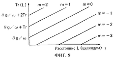
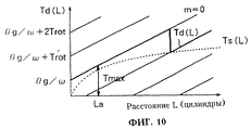
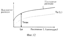
Кроме того, в способе управления доступом к диску для записи данных, согласно настоящему изобретению, предпочтительно на этапе планирования изменяют порядок множества запросов на доступ к диску так, что они распределяются в порядке, начиная с ближайшего к головке, при движении головки от текущей позиции по направлению к позиции на внутренней дорожке диска для записи данных, а этап определения положения блока данных на диске для записи данных осуществляют на основании дополнительно к сдвигу интервала, указывающего угловую разность между началом и окончанием одного и того же блока данных так, что разность между временем задержки вращения Tr, в данном случае - временем ожидания, обусловленного вращением диска для записи данных Td(L) и временем поиска Ts(L) вблизи среднего расстояния поиска La мала по сравнению с периодом вращения, при этом:
Td(L) = (L•Bc•θs+θg+2mπ)/ω (2)
La=Lt/(N-l), (3)
где L - расстояние поиска, выраженное через количество цилиндров,
Bc - количество блоков данных в одном цилиндре,
θs - сдвиг, измеряемый в радианах,
θg - интервал, измеряемый в радианах,
ω - скорость вращения диска для записи данных, рад/сек,
Lt - максимальное значение расстояния между положениями доступа при упорядочении запросов доступа, выраженное через количество цилиндров,
N - количество обращений, которые могут быть одновременно обработаны, и
m - выбрано так, чтобы стать минимальным в диапазоне, где Td(L) превышает время поиска Ts(L) на расстоянии L поиска.In addition, in the method of controlling access to the disk for recording data according to the present invention, preferably, at the planning stage, the order of the set of requests for access to the disk is changed so that they are distributed in the order starting from the one closest to the head when moving the head from the current position along toward the position on the inner track of the disk for recording data, and the step of determining the position of the data block on the disk for recording data is carried out based on, in addition to the shift of the interval indicating the angular difference between the beginning and end of the same data block so that the difference between the rotation delay time Tr, in this case, the waiting time due to the rotation of the disk for recording data Td (L) and the search time Ts (L) near the average search distance La is small in compared with the rotation period, while:
Td (L) = (L • Bc • θs + θg + 2mπ) / ω (2)
La = Lt / (Nl), (3)
where L is the search distance expressed in terms of the number of cylinders,
Bc - the number of data blocks in one cylinder,
θs is the shift measured in radians,
θg is the interval measured in radians,
ω is the rotation speed of the disk for recording data, rad / sec,
Lt is the maximum value of the distance between access positions when ordering access requests, expressed in terms of the number of cylinders,
N is the number of calls that can be processed simultaneously, and
m - is chosen so as to become minimal in the range where Td (L) exceeds the search time Ts (L) at the search distance L.
Кроме того, в способе управления доступом к диску для записи данных, согласно настоящему изобретению, предпочтительно на этапе планирования изменяют порядок множества запросов на доступ к диску для записи данных для их упорядочивания в процессе появления при перемещении головки от текущего положения по направлению к внутренней дорожке или внешней дорожке диска для записи данных, а этап определения положения блока данных на диске для записи данных осуществляют на основании, дополнительно к сдвигу интервала, указывающего угловую разность между началом и окончанием одного и того же блока данных так, чтобы время ожидания, обусловленное вращением диска для записи данных Td(L) было всегда больше времени поиска Ts(L), и разность между временем Td(L) и временем Ts(L) стала малой по сравнению с периодом вращения диска для записи данных, причем:
Td(L) = (L•Bc•θs+θg)/ω, (4)
где L - расстояние поиска, выраженное через количество цилиндров,
Bc - количество блоков данных в одном цилиндре,
θs - сдвиг, измеряемый в радианах,
θg - интервал, измеряемый в радианах,
ω - скорость вращения диска для записи данных, рад/с.In addition, in the method of controlling access to a disk for recording data according to the present invention, preferably, at the planning stage, the order of a plurality of requests for access to a disk for recording data is rearranged in order to arrange them when they appear when moving the head from its current position toward the inner track or the external track of the disk for recording data, and the step of determining the position of the data block on the disk for recording data is carried out on the basis of, in addition to the shift of the interval indicating the angular separation b between the beginning and end of the same data block so that the waiting time due to the rotation of the disk for recording data Td (L) is always greater than the search time Ts (L), and the difference between the time Td (L) and the time Ts (L ) became small compared to the period of rotation of the disk for recording data, moreover:
Td (L) = (L • Bc • θs + θg) / ω, (4)
where L is the search distance expressed in terms of the number of cylinders,
Bc - the number of data blocks in one cylinder,
θs is the shift measured in radians,
θg is the interval measured in radians,
ω is the rotational speed of the disk for recording data, rad / s.
Кроме того, в способе управления доступом к диску для записи данных, согласно настоящему изобретению, предпочтительно разделяют диск для записи данных на первые области для использования в случае перемещения головки от внутренней дорожки к внешней дорожке, и вторые области для использования в случае перемещения головки от внешней дорожки к внутренней дорожке, и при осуществлении этапа определения положения блока данных на диске для записи данных определяют положение блока данных на основании оптимальных значений сдвига и интервала, указывающего угловую разность между началом и окончанием одного и того же блока данных, в соответствующих областях с учетом направления перемещения головки, а на этапе планирования селективно обращаются только к первым и вторым областям в соответствии с направлением перемещения головки. In addition, in the method for controlling access to the data recording disk according to the present invention, it is preferable to divide the data recording disk into first areas for use in the case of moving the head from the internal track to the external track, and second areas for use in the case of moving the head from the external track track to the internal track, and in the implementation of the step of determining the position of the data block on the disk for recording data, determine the position of the data block based on the optimal values of the shift and interval indicating the angular difference between the beginning and the end of the same data block, in the corresponding areas, taking into account the direction of movement of the head, and at the planning stage, selectively refer only to the first and second areas in accordance with the direction of movement of the head.
Кроме того, в способе управления доступом к диску для записи данных, согласно настоящему изобретению, предпочтительно первые области и вторые области на диске для записи данных разделяют его на множество, состоящее, по меньшей мере, из двух частей в радиальном направлении, причем первые области и вторые области определяют так, что они распределены от крайней внутренней дорожки к крайней внешней дорожке на диске. Furthermore, in the method for controlling access to a data recording disk according to the present invention, preferably, the first regions and second regions on the data recording disk divide it into a plurality of at least two parts in the radial direction, the first regions and the second areas are defined so that they are distributed from the extreme inner track to the extreme outer track on the disk.
Также поставленная задача может быть решена с помощью применения устройства управления доступом к диску для записи данных, содержащего средство определения сдвига, для определения сдвига, указывающего угловую разность в направлении вращения диска для записи данных между началами соседних блоков данных, который минимизирует время ожидания, обусловленное вращением диска для записи данных на среднем расстоянии перемещения головки при обращении головки к диску для записи данных, средство упорядочения блоков данных для определения положения блока данных на диске для записи данных на основании, по меньшей мере, определенного сдвига, и средство планирования для планирования порядка множества входных запросов на обращение к диску для записи данных так, чтобы величина перемещения головки была малой во время обращения головки к диску для записи данных, при этом головка выполнена с возможностью обращения к диску для записи данных на основании результатов планирования. Also, the problem can be solved by using a disk access control device for recording data containing a shift detection means for determining a shift indicating an angular difference in the direction of rotation of the disk for recording data between the beginnings of adjacent data blocks, which minimizes the latency caused by rotation a disk for recording data at an average distance of movement of the head when the head is turned to a disk for recording data, a means of organizing data blocks to determine the position a data block on the disk for recording data based on at least a certain shift, and planning means for planning the order of a plurality of input requests to access the disk to write data so that the amount of head movement is small during the head access to the disk for recording data, while the head is made with the possibility of access to the disk to record data based on the planning results.
При этом в устройстве управления доступом к диску для записи данных, согласно настоящему изобретению, средство упорядочения блоков данных предпочтительно выполнено с возможностью определения положения блоков данных, дополнительно к сдвигу, на основании интервала, указывающего угловую разность между началом и концом одного и того же блока данных. Moreover, in the disk access control device for recording data according to the present invention, the data block sequencer is preferably configured to determine the position of the data blocks, in addition to a shift, based on an interval indicating the angular difference between the beginning and end of the same data block .
При этом в устройстве управления доступом к диску для записи данных, согласно настоящему изобретению, средство упорядочения блоков данных предпочтительно выполнено с возможностью определения комбинаций данных, каждая из которых представляет собой комбинацию сдвига и интервала для множества блоков данных и селективного использования комбинаций данных в соответствии с положением каждого блока данных на диске для записи данных. Moreover, in the disk access control device for recording data according to the present invention, the data block organizing means is preferably configured to determine data combinations, each of which is a combination of a shift and an interval for a plurality of data blocks and selectively using data combinations in accordance with the position each data block on the disk to record data.
При этом в устройстве управления доступом к диску для записи данных, согласно настоящему изобретению, средство упорядочения блоков данных предпочтительно выполнено с возможностью изменения размера блока данных так, чтобы интервал, указывающий угловую разность между началом и окончанием одного и того же блока данных, был постоянным по всей области от внешнего края до внутреннего края диска для записи данных. Moreover, in the disk access control device for recording data according to the present invention, the data block organizing means is preferably configured to resize the data block so that the interval indicating the angular difference between the beginning and end of the same data block is constant the entire area from the outer edge to the inner edge of the disc for recording data.
При этом в устройстве управления доступом к диску для записи данных, согласно настоящему изобретению, средство определения сдвига предпочтительно выполнено с возможностью определения сдвига в соответствии с изменением интервала, указывающего угловую разность между началом и окончанием одного и того же блока данных, на основании разности радиусов дорожек записи. Moreover, in the disk access control device for recording data according to the present invention, the shift detecting means is preferably configured to detect a shift in accordance with a change in the interval indicating an angular difference between the beginning and end of the same data block based on the difference of the radii of the tracks records.
При этом в устройстве управления доступом к диску для записи данных, согласно настоящему изобретению, средство планирования предпочтительно выполнено с возможностью изменения порядка множества запросов на доступ к диску для записи данных так, чтобы они были упорядочены, начиная от наиболее близкого к головке при перемещении ее от текущего положения по направлению к позиции на внутренней дорожке или внешней дорожке диска для записи данных, а средство упорядочения блоков данных выполнено с возможностью определения положения блока данных на диске для записи данных на основании, дополнительно к сдвигу, интервала, указывающего угловую разность между началом и концом одного и того же блока данных так, чтобы разность между заданным временем ожидания, обусловленным вращением диска для записи данных Td(L) и временем поиска Ts(L) вблизи среднего расстояния поиска La, заданного нижеследующим уравнением (6), стала малой по сравнению с периодом вращения диска для записи данных, при этом:
Td(L) = (L•Bc•θs+θg+2mπ)/ω, (5)
La=Lt/(N-1), (6)
где L - расстояние поиска, выраженное через количество цилиндров,
Bc - количество блоков данных в одном цилиндре,
θs - сдвиг, измеряемый в радианах,
θg - интервал, измеряемый в радианах,
ω - скорость вращения диска для записи данных, рад/с,
Lt - максимальное значение расстояния между положениями доступа при упорядочении запросов доступа, выраженное через количество цилиндров,
N - количество обращений, которые могут быть одновременно обработаны, и
m - выбрано так, чтобы стать минимальным в диапазоне, где Td(L) превышает время поиска Ts(L) на расстоянии L поиска.Moreover, in the disk access control device for recording data according to the present invention, the scheduling means is preferably configured to change the order of a plurality of disk access requests for recording data so that they are ordered starting from the closest to the head when moving it from the current position towards the position on the inner track or the outer track of the disk for recording data, and the means for organizing data blocks is configured to determine the position of the data block x on the disk for recording data on the basis of, in addition to the shift, an interval indicating the angular difference between the beginning and end of the same data block so that the difference between the specified wait time due to the rotation of the disk for recording data Td (L) and the search time Ts (L) near the average search distance La defined by the following equation (6), became small compared to the rotation period of the disk for recording data, while:
Td (L) = (L • Bc • θs + θg + 2mπ) / ω, (5)
La = Lt / (N-1), (6)
where L is the search distance expressed in terms of the number of cylinders,
Bc - the number of data blocks in one cylinder,
θs is the shift measured in radians,
θg is the interval measured in radians,
ω is the rotation speed of the disk for recording data, rad / s,
Lt is the maximum value of the distance between access positions when ordering access requests, expressed in terms of the number of cylinders,
N is the number of calls that can be processed simultaneously, and
m - is chosen so as to become minimal in the range where Td (L) exceeds the search time Ts (L) at the search distance L.
При этом в устройстве управления доступом к диску для записи данных, согласно настоящему изобретению, средство планирования предпочтительно выполнено с возможностью изменения порядка множества запросов на доступ к диску для записи данных для их упорядочивания в порядке появления при перемещении головки от текущего положения по направлению к позиции либо на внутренней дорожке, либо на внешней дорожке диска для записи данных, а средство упорядочения блоков данных выполнено с возможностью определения положения блоков данных на диске для записи данных на основании дополнительно к сдвигу интервала так, чтобы время ожидания, обусловленного вращением диска для записи данных Td(L), заданное нижеследующим уравнением, было всегда больше времени поиска Ts(L), а разность между временем Td(L) и временем Ts(L) стала малой по сравнению с периодом вращения диска для записи данных, при этом:
Td(L) = (L•Bc•θs+θg)/ω, (7)
где L - расстояние поиска, выраженное через количество цилиндров,
Bc - количество блоков данных в одном цилиндре,
θs - сдвиг, измеряемый в радианах,
θg - интервал, измеряемый в радианах,
ω - скорость вращения диска для записи данных, рад/с.Moreover, in the disk access control device for recording data according to the present invention, the scheduling means is preferably configured to change the order of a plurality of disk access requests for recording data to arrange them in order of appearance when moving the head from the current position towards the position or on the internal track or on the external track of the disk for recording data, and the means for organizing the data blocks is configured to determine the position of the data blocks on the disk for recording data based on, in addition to the interval shift, so that the waiting time due to the rotation of the data recording disk Td (L) given by the following equation is always greater than the search time Ts (L), and the difference between the time Td (L) and the time Ts (L) became small compared to the period of rotation of the disk for recording data, while:
Td (L) = (L • Bc • θs + θg) / ω, (7)
where L is the search distance expressed in terms of the number of cylinders,
Bc - the number of data blocks in one cylinder,
θs is the shift measured in radians,
θg is the interval measured in radians,
ω is the rotational speed of the disk for recording data, rad / s.
При этом устройство управления доступом к диску для записи данных, согласно настоящему изобретению, предпочтительно выполнено с возможностью использования диска для записи данных, который разделен на первые области, для использования при перемещении головки от внутренней дорожки к внешней дорожке, и вторые области для использования в случае перемещения головки от внешней дорожки к внутренней дорожке, и средство упорядочения блоков данных выполнено с возможностью определения положения блока данных на диске для записи данных на основании оптимальных значений сдвига и интервала, указывающего угловую разность между началом и окончанием одного и того же блока данных, в соответствующих областях на основании направления перемещения головки, а средство планирования обеспечивает селективное обращение только к первым и вторым областям в соответствии с направлением перемещения головки. Moreover, the disk access control device for recording data according to the present invention is preferably configured to use a data recording disk, which is divided into first areas, for use when moving the head from the internal track to the external track, and second areas for use in the case moving the head from the outer track to the inner track, and the means for organizing the data blocks is configured to determine the position of the data block on the disk to write data to the base ii optimal interval and offset values indicating the angular difference between the start and the end of the same data block in the respective regions based on the direction of movement of the head, and the scheduling means provides selective treatment of only the first and second regions in accordance with the direction of movement of the head.
При этом устройство управления доступом к диску для записи данных, согласно настоящему изобретению, предпочтительно выполнено с возможностью использования диска для записи данных, в котором первые области и вторые области разделяют его на множество, состоящее, по меньшей мере, из двух частей, вдоль радиального направления, причем первые области и вторые области определены так, что они распределены от крайней внутренней дорожки к крайней внешней дорожке на диске для записи данных. Moreover, the disk access control device for recording data according to the present invention is preferably configured to use a data recording disk in which the first regions and second regions divide it into a plurality of at least two parts along the radial direction moreover, the first areas and second areas are defined so that they are distributed from the extreme internal track to the extreme external track on the disk for recording data.
Кроме того, поставленная задача решается тем, что способ управления доступом к диску для записи данных содержит этапы определения положения блока данных на диске для записи данных для минимизации времени ожидания, обусловленного вращением диска для записи данных на среднем расстоянии перемещения головки при обращении головки к диску для записи данных, планирования порядка множества входных запросов доступа к диску для записи данных для минимизации величины перемещения головки при обращении головки к диску для записи данных, и доступа к диску для записи данных посредством головки на основании результатов планирования. In addition, the problem is solved in that the method of controlling access to the disk for recording data includes the steps of determining the position of the data block on the disk for recording data to minimize the latency caused by the rotation of the disk for recording data at an average distance of movement of the head when the head is turned to the disk for data recording, planning the order of the set of input disk access requests for data recording to minimize the amount of head movement when the head accesses the disk to record data, and access to a disk for recording data by means of a head based on planning results.
Также в способе управления доступом к диску для записи данных предпочтительно этап определения положения дополнительно содержит этапы определения сдвига, указывающего угловую разность в направлении вращения диска для записи данных между началами соседних блоков данных, который минимизирует время ожидания, обусловленное вращением диска для записи данных на среднем расстоянии перемещения головки при обращении головки к диску для записи данных, и определения положения блока данных на нем на основании, по меньшей мере, определенного сдвига. Also in the method of controlling access to the disk for recording data, preferably the step of determining the position further comprises the steps of determining a shift indicating an angular difference in the direction of rotation of the disk for recording data between the beginnings of adjacent data blocks, which minimizes the latency caused by the rotation of the disk for recording data at an average distance moving the head when the head is turned to the disk for recording data, and determining the position of the data block on it based on at least a certain shift yoke.
Также в способе управления доступом к диску для записи данных предпочтительно этап определения положения предпочтительно включает определение положения блока данных на диске для записи данных на основании, дополнительно к сдвигу интервала, указывающего угловую разность между началом и концом одного и того же блока данных. Also in the method of controlling access to the disk for recording data, preferably the step of determining the position preferably includes determining the position of the data block on the disk to record data based on, in addition to shifting the interval indicating the angular difference between the beginning and end of the same data block.
При этом поставленная задача может быть решена с помощью устройства управления доступом к диску для записи данных, содержащего средство определения положения блока данных на диске для записи данных для минимизации времени ожидания, обусловленного вращением диска для записи данных на среднем расстоянии перемещения головки при обращении головки к диску для записи данных, средство планирования порядка множества запросов доступа для минимизации величины перемещения головки при ее обращении к диску для записи данных, и средство для доступа к диску для записи данных с помощью головки на основании результатов планирования. In this case, the task can be solved using a disk access control device for recording data, comprising means for determining the position of the data block on the disk for recording data to minimize the latency caused by the rotation of the disk for recording data at an average head movement distance when the head is turned to the disk for recording data, means for planning the order of a plurality of access requests to minimize the amount of head movement when it is accessed by a disk for recording data, and means for accessing a disk for recording data with the head on the basis of the planning results.
Кроме того, в устройстве управления доступом к диску для записи данных средство определения положения блока данных предпочтительно содержит средство для определения сдвига, указывающего угловую разность в направлении вращения диска для записи данных между началами соседних блоков данных, который минимизирует время ожидания, обусловленное вращением диска для записи данных на среднем расстоянии перемещения головки при обращении головки к диску для записи данных и средство для определения положения блока данных на диске для записи данных на основании, по меньшей мере, определенного сдвига. In addition, in the data access disk access control device, the data unit position determining means preferably comprises a means for determining a shift indicating an angular difference in the direction of rotation of the disk for recording data between the beginnings of adjacent data units, which minimizes the latency caused by the rotation of the recording disk data at an average distance of movement of the head when the head is turned to the disk for recording data and means for determining the position of the data block on the disk for recording is given s on the basis of at least the determined shift.
Кроме того, в устройстве управления доступом к диску для записи данных средство определения положения блока данных на диске для записи данных предпочтительно выполнено с возможностью определения положения блока данных на диске на основании дополнительно к сдвигу интервала, указывающего угловую разность между началом и окончанием одного и того же блока данных. In addition, in the disk access control device for recording data, the means for determining the position of the data block on the disk for recording data is preferably configured to determine the position of the data block on the disk based on, in addition to the offset of the interval indicating the angular difference between the start and end of the same data block.
Также поставленная задача может быть решена с помощью устройства управления доступом к диску для записи данных, содержащего средство определения сдвига, указывающего угловую разность в направлении вращения диска для записи данных между началами соседних блоков данных, который минимизирует время ожидания, обусловленное вращением диска для записи данных на среднем расстоянии перемещения головки при обращении головки к диску для записи данных, устройство распределения блока данных для определения положения блока данных на диске для записи данных на основании, по меньшей мере, определенного сдвига, и средство планирования для планирования порядка множества входных запросов на обращение к диску для записи данных так, чтобы величина перемещения головки была малой во время обращения головки к диску для записи данных, при этом головка выполнена с возможностью обращения к диску для записи данных на основании результатов планирования. Also, the problem can be solved using a disk access control device for recording data, comprising a shift detection means indicating an angular difference in the direction of rotation of the disk for recording data between the beginnings of adjacent data blocks, which minimizes the latency caused by the rotation of the disk for recording data on the average distance of movement of the head when the head is turned to the disk for recording data, the distribution unit of the data block to determine the position of the data block on the disk for data on the basis of at least a certain shift, and planning means for planning the order of the set of input requests to access the disk for recording data so that the amount of movement of the head was small during the rotation of the head to the disk for recording data, while the head is made with the ability to access the disk to record data based on the results of planning.
При этом в устройстве управления доступом к диску для записи данных устройство распределения блоков данных предпочтительно выполнено с возможностью определения положения блоков данных на основании, дополнительно к сдвигу интервала, указывающего угловую разность между началом и концом одного и того же блока данных. Moreover, in the disk access control device for recording data, the data block distribution device is preferably configured to determine the position of the data blocks based on, in addition to a shift of the interval indicating the angular difference between the beginning and the end of the same data block.
При этом в устройстве управления доступом к диску для записи данных устройство распределения блоков данных предпочтительно выполнено с возможностью определения комбинаций данных, каждая из которых представляет собой комбинацию сдвига и интервала для множества блоков данных, и селективного использования комбинаций данных в соответствии с положением каждого блока данных на диске для записи данных. Moreover, in the disk access control device for recording data, the data block distribution device is preferably configured to determine data combinations, each of which is a combination of a shift and an interval for a plurality of data blocks, and selectively use data combinations in accordance with the position of each data block on disk for data recording.
При этом в устройстве управления доступом к диску для записи данных устройство распределения блоков данных предпочтительно выполнено с возможностью изменения размера блока данных так, чтобы интервал, указывающий угловую разность между началом и окончанием одного и того же блока данных, был постоянным по всей области от внешнего края до внутреннего края диска для записи данных. Moreover, in the disk access control device for recording data, the data block distribution device is preferably configured to resize the data block so that the interval indicating the angular difference between the start and end of the same data block is constant over the entire area from the outer edge to the inside edge of the disc to record data.
При этом в устройстве управления доступом к диску для записи данных средство определения сдвига предпочтительно выполнено с возможностью определения сдвига в соответствии с изменением интервала, указывающего угловую разность между началом и окончанием одного и того же блока данных, на основании разности радиусов дорожек записи. Moreover, in the disk access control device for recording data, the shift determination means is preferably configured to determine the shift in accordance with a change in the interval indicating the angular difference between the beginning and the end of the same data block based on the difference of the radii of the recording tracks.
При этом в устройстве управления доступом к диску для записи данных средство планирования предпочтительно выполнено с возможностью изменения порядка множества запросов на доступ к диску для записи данных так, чтобы они были упорядочены, начиная от наиболее близкого к головке при перемещении головки от текущего положения по направлению к позиции на внутренней дорожке или внешней дорожке диска для записи данных, а устройство распределения блоков данных выполнено с возможностью определения положения блока данных на диске для записи данных на основании, дополнительно к сдвигу интервала, указывающего угловую разность между началом и концом одного и того же блока данных так, чтобы разность между заданным временем ожидания, обусловленным вращением диска для записи данных Td(L) и временем поиска Ts(L) вблизи среднего расстояния La поиска, определяемого нижеследующим уравнением (9), стала достаточно малой по сравнению с периодом вращения диска для записи данных, при этом:
Td(L) = (L•Bc•θs+θg+2mπ)/ω, (8)
La=Lt/(N-1), (9)
где L - расстояние поиска, выраженное через количество цилиндров,
Bc - количество блоков данных в одном цилиндре,
θs - сдвиг, измеряемый в радианах,
θg - интервал, измеряемый в радианах,
ω - скорость вращения диска для записи данных, рад/с,
Lt - максимальное значение расстояния между положениями доступа при упорядочении запросов доступа, выраженное через количество цилиндров,
N - количество обращений, которые могут быть одновременно обработаны, и
m - выбрано так, чтобы стать минимальным в диапазоне, где Td(L) превышает время поиска Ts(L) на расстоянии L поиска.Moreover, in the disk access control device for recording data, the scheduling means is preferably configured to change the order of the set of disk access requests for recording data so that they are ordered, starting from the closest to the head when moving the head from the current position towards position on the internal track or external track of the disk for recording data, and the distribution unit of the data blocks is configured to determine the position of the data block on the disk for recording data based on, in addition to the shift of the interval indicating the angular difference between the beginning and the end of the same data block so that the difference between the specified waiting time due to the rotation of the disk for recording data Td (L) and the search time Ts (L) near the average the search distance La, defined by the following equation (9), has become quite small compared with the period of rotation of the disk to record data, while:
Td (L) = (L • Bc • θs + θg + 2mπ) / ω, (8)
La = Lt / (N-1), (9)
where L is the search distance expressed in terms of the number of cylinders,
Bc - the number of data blocks in one cylinder,
θs is the shift measured in radians,
θg is the interval measured in radians,
ω is the rotation speed of the disk for recording data, rad / s,
Lt is the maximum value of the distance between access positions when ordering access requests, expressed in terms of the number of cylinders,
N is the number of calls that can be processed simultaneously, and
m - is chosen so as to become minimal in the range where Td (L) exceeds the search time Ts (L) at the search distance L.
При этом в устройстве управления доступом к диску для записи данных средство планирования предпочтительно выполнено с возможностью изменения порядка множества запросов на доступ к диску для записи данных так, чтобы они были упорядочены в порядке появления, когда головка перемещается от текущего положения по направлению к внутренней дорожке или внешней дорожке диска для записи данных, а устройство распределения блоков данных выполнено с возможностью определения положения блоков данных на диске для записи данных, дополнительно к сдвигу, на основании интервала, указывающего угловую разность между началом и окончанием одного и того же блока данных так, чтобы время ожидания, обусловленное вращением диска для записи данных Td(L), заданное нижеследующим уравнением, было всегда больше времени поиска Ts(L), и разность между временем Td(L) и временем Ts(L) стала малой по сравнению с периодом вращения диска для записи данных, где
Td(L) = (L•Bc•θs+θg)/ω (10)
где L - расстояние поиска, выраженное через количество цилиндров,
Bc - количество блоков данных в одном цилиндре,
θs - сдвиг, измеряемый в радианах,
θg - интервал, измеряемый в радианах,
ω - скорость вращения диска для записи данных, рад/с.Moreover, in the disk access control device for recording data, the scheduling means is preferably configured to change the order of a plurality of disk access requests for recording data so that they are ordered in the order of appearance when the head moves from the current position toward the inner track or an external disc track for recording data, and a data block distribution device is configured to determine a position of data blocks on a disc for recording data, in addition to a shift , based on the interval indicating the angular difference between the beginning and end of the same data block so that the waiting time due to the rotation of the data recording disk Td (L) given by the following equation is always longer than the search time Ts (L), and the difference between the time Td (L) and the time Ts (L) became small compared to the period of rotation of the disk for recording data, where
Td (L) = (L • Bc • θs + θg) / ω (10)
where L is the search distance expressed in terms of the number of cylinders,
Bc - the number of data blocks in one cylinder,
θs is the shift measured in radians,
θg is the interval measured in radians,
ω is the rotational speed of the disk for recording data, rad / s.
При этом устройство управления доступом к диску для записи данных предпочтительно выполнено с возможностью использования диска для записи данных, который разделен на первые области, для использования при перемещении головки от внутренней дорожки к внешней дорожке, и вторые области для использования в случае перемещения головки от внешней дорожки к внутренней дорожке, и средство упорядочения блоков данных выполнено с возможностью определения положения блока данных на диске для записи данных на основании оптимальных значений сдвига и интервала, указывающего угловую разность между началом и окончанием одного и того же блока данных, в соответствующих областях на основании направления перемещения головки, а средство планирования обеспечивает селективное обращение только к первым и вторым областям в соответствии с направлением перемещения головки. Moreover, the disk access control device for recording data is preferably configured to use a disk for recording data, which is divided into first areas for use when moving the head from the internal track to the external track, and second areas for use in case of moving the head from the external track to the inner track, and the data block sequencer is configured to determine the position of the data block on the disk to record data based on the optimal shift values and ntervala indicating the angular difference between the start and the end of the same data block in the respective regions based on the direction of movement of the head, and the scheduling means provides selective treatment of only the first and second regions in accordance with the direction of movement of the head.
При этом устройство управления доступом к диску для записи данных предпочтительно выполнено с возможностью использования диска для записи данных, в котором первые области и вторые области разделяют его на множество, состоящее, по меньшей мере, из двух частей, вдоль радиального направления, причем первые области и вторые области определены так, что они распределены от крайней внутренней дорожки к крайней внешней дорожке на диске для записи данных. The device for controlling access to the disk for recording data is preferably configured to use a disk for recording data, in which the first regions and second regions divide it into a plurality of at least two parts along the radial direction, the first regions and the second areas are defined so that they are distributed from the outermost track to the outermost track on the disc for recording data.
Краткое описание чертежей
Указанные и другие задачи и особенности настоящего изобретения станут более ясными из последующего описания предпочтительных вариантов воплощения, приведенных со ссылками на чертежи, на которых представлено следующее:
фиг. 1 - схематичное представление для пояснения предшествующего уровня техники,
фиг. 2 - блок-схема конфигурации устройства для управления доступом к диску для записи данных в соответствии с первым вариантом воплощения настоящего изобретения,
фиг. 3 - блок-схема последовательности операций при обработке в устройстве распределения блоков, изображенном на фиг. 2,
фиг. 4 - блок-схема последовательности операций при обработке в устройстве планирования, изображенном на фиг. 2,
фиг. 6 - схематичное представление, поясняющее способ упорядочения блоков на диске устройством распределения блоков,
фиг. 7 - диаграмма, поясняющая содержание карты распределения блоков,
фиг. 8 - диаграмма, поясняющая содержание обработки на этапе S3, изображенном на фиг.3,
фиг. 9 - график, поясняющий содержание обработки на этапе S3, изображенном на фиг.3,
фиг. 10 - график, поясняющий накладные расходы в случае, когда учитываются и поиск, и задержка вращения,
фиг. 11A, 11B и 11C - диаграммы, поясняющие возможный пример распределения обращений на диске,
фиг. 12 - график, иллюстрирующий накладные расходы для обычного SCAN- алгоритма,
фиг. 13 - график, поясняющий соотношение между расстоянием L поиска и задержкой в случае использования возрастающей выпуклой функции, огибающей пилообразную функцию,
фиг. 14 - диаграмма, поясняющая обработку в устройстве распределения блоков устройства управления доступом к диску для записи данных согласно второму варианту воплощения настоящего изобретения,
фиг. 15 - блок-схема последовательности операций, поясняющая обработку в устройстве распределения блоков в устройстве управления доступом к диску для записи данных, изображенном на фиг. 14,
фиг. 16 - диаграмма, поясняющая содержание карты распределения блоков в устройстве управления доступом к диску для записи данных, изображенном на фиг. 13.Brief Description of the Drawings
These and other objects and features of the present invention will become more apparent from the following description of preferred embodiments given with reference to the drawings, in which the following is presented:
FIG. 1 is a schematic diagram for explaining the prior art,
FIG. 2 is a block diagram of a configuration of a disk access control apparatus for recording data in accordance with a first embodiment of the present invention,
FIG. 3 is a flowchart for processing in the block distribution device shown in FIG. 2
FIG. 4 is a flowchart for processing in the planning device shown in FIG. 2
FIG. 6 is a schematic diagram illustrating a method for arranging blocks on a disk with a block distribution device,
FIG. 7 is a diagram explaining the contents of a block distribution map,
FIG. 8 is a diagram explaining the contents of the processing in step S3 shown in FIG. 3,
FIG. 9 is a graph explaining the contents of the processing in step S3 shown in FIG. 3,
FIG. 10 is a graph explaining overhead in the case where both search and rotation delay are taken into account,
FIG. 11A, 11B and 11C are diagrams illustrating a possible example of distribution of disk accesses,
FIG. 12 is a graph illustrating overhead for a conventional SCAN algorithm,
FIG. 13 is a graph explaining the relationship between the search distance L and the delay in the case of using an increasing convex function enveloping the sawtooth function,
FIG. 14 is a diagram illustrating processing in a block distribution device of a disk access control device for recording data according to a second embodiment of the present invention,
FIG. 15 is a flowchart for explaining processing in a block distribution device in a disk access control device for recording data shown in FIG. fourteen,
FIG. 16 is a diagram explaining the contents of a block allocation map in a disk access control device for recording data shown in FIG. thirteen.
Предпочтительные варианты осуществления изобретения
Ниже приводится объяснение способа и устройства управления доступом к диску для записи данных согласно вариантам воплощения настоящего изобретения.Preferred Embodiments
The following is an explanation of a method and apparatus for controlling disk access for recording data according to embodiments of the present invention.
Первый вариант воплощения
Фиг.2 изображает блок-схему конфигурации устройства для управления доступом к диску для записи данных согласно настоящему варианту воплощения изобретения.The first embodiment
Figure 2 depicts a block diagram of a configuration of a device for controlling access to a disk for recording data according to the present embodiment of the invention.
Устройство управления доступом к диску для записи данных, согласно настоящему варианту воплощения, реализуется работой программного обеспечения, например, в компьютере. Каждый блок, изображенный на фиг.2, представляет собой основной программный модуль или основную структуру данных. A disk access control device for recording data according to the present embodiment is implemented by software operation, for example, in a computer. Each block depicted in FIG. 2 represents a main program module or a basic data structure.
Устройство 1 распределения блоков (средство упорядочения) определяет, как данные упорядочены на диске 5 на основании заданного параметра 10 формата. Диск 5 может быть, например, магнитным диском, магнито-оптическим диском или жестким диском. The block allocation device 1 (sequencer) determines how data is arranged on
Параметр 10 формата включает в себя размер первого блока данных, среднее расстояние La перемещения головки при выполнении SCAN-планирования, функцию Ts(L) времени поиска используемого дисковода и физический формат диска 5. The
Среднее расстояние La перемещения головки определяется следующим уравнением (8), исходя из общего количества цилиндров Lt диска и количества N обращений, обработанных посредством одного сканирования. The average head moving distance La is determined by the following equation (8), based on the total number of disc cylinders Lt and the number N of calls processed by one scan.
La=Lt/(N-1) (8)
Время поиска Ts(L) для дисковода является функцией расстояния L поиска (количества цилиндров). Его значение определяется механическими характеристиками используемого дисковода. Пример изображен на фиг.5. Насколько много запросов обрабатываются одновременно при сканировании, определяется особенностями системы, использующей этот диск, требуемой эффективностью, величиной буферной памяти, которая может быть использована, и т.д. Чем больше количество N запросов на обращение, которые должны быть сканированы вместе, тем более высокую эффективность случайного доступа должен иметь диск, но существует побочный эффект, заключающийся в том, что время отклика увеличивается, когда величина требуемой буферной памяти увеличивается.La = Lt / (N-1) (8)
The seek time Ts (L) for the drive is a function of the search distance L (number of cylinders). Its value is determined by the mechanical characteristics of the drive used. An example is shown in FIG. How many requests are processed simultaneously during scanning is determined by the features of the system using this disk, the required efficiency, the amount of buffer memory that can be used, etc. The greater the number N of access requests that must be scanned together, the higher the random access must have the drive, but there is a side effect that the response time increases when the size of the required buffer memory increases.
Эти параметры 10 формата определяются центральным процессором (не изображен), имеющим управляющую программу, которая управляет всей системой, и эти параметры 10 формата подаются в устройство 1 распределения блоков. В примере, в котором данный вариант воплощения используется для нелинейного редактирования, устройству 1 распределения блоков были заданы N = 10, a La = 300. Кроме того, размер первого блока данных соответствует одному листу данных образа и составляет приблизительно 700 К. (килобайт) в случае использования вещающими станциями формата CCIR-601 и т.д. Конечно, эти количественные характеристики могут быть произвольно установлены в соответствии с назначением и различными специальными техническими условиями. These
Устройство 1 распределения блоков на основании заданного параметра 10 формата определяет, в какую позицию на диске 5 должен быть помещен каждый блок. В данном примере один блок равен одному кадру изображения, но, конечно, основная концепция аналогична как при работе с данными, полученными путем деления MPEG-данных или другого сжатого изображения на подходящие длины, так и с аудиоданными. The
К диску 5 может быть осуществлен доступ к каждой области, которая обычно называется "сектором". Один сектор обычно имеет размер от 512 байт до приблизительно 4 К. Область в виде тороида, в которой эти сектора образуют окружность, называют "дорожкой". Далее, цилиндрическая область, содержащая группу одинаковых дорожек из перекрывающегося множества магнитных сред, называется "цилиндром".
Один блок видео- или аудиоданных обычно больше одного сектора, поэтому устройство 1 распределения блоков назначает множество секторов для каждого блока. Фиг.5 изображает простой пример для случая, когда существует одна магнитная среда (носитель информации). Заштрихованная часть на фиг.6, т.е. полная окружность дорожки "1", и сектора от "0" до "6" дорожки "2" соответствуют одному блоку. В этом примере, поскольку существует только один носитель, то термины "дорожка" и "цилиндр" имеют одно и то же значение, но в случае дисковода, имеющего множество магнитных дисков, при полностью используемых всех частях одного цилиндра блоки назначаются с возможностью использования соседних цилиндров. One block of video or audio data is usually more than one sector, therefore, the
Распределение на сектора выполняется для всех блоков. Результат записывается в карту 3 распределения блоков, после чего работа устройства 1 распределения блоков заканчивается. Устройство 1 распределения блоков обозначает позицию сектора путем установки номера цилиндра, номера носителя (который по счету слой носителя) и номера сектора. Однако, в дисководах спецификации SCSI (ANSI интерфейс малой компьютерной системы), которые становятся наиболее популярны в последние годы, последовательные номера (локальные номера секторов, называемые в SCSI "адресами логических блоков", здесь называются номерами логических секторов так, чтобы избежать путаницы с блоками видео- и аудиоданных) присваиваются всем секторам в дисководе и используются для доступа к данным. По этой причине соответствие между номерами логических секторов, определенное с помощью диска, и физическими адресами, т. е. номерами цилиндров, номерами среды и номерами секторов, предварительно запоминается в таблице 7 физических адресов. Устройство 1 распределения блоков преобразует требуемый физический адрес в номер логического сектора, определенный SCSI, обращаясь к таблице 7, и вносит его в карту 3 распределения блоков. Sector allocation is performed for all blocks. The result is recorded in the
Фиг. 7 изображает пример карты распределения блоков. Информация, соответствующая блоку "0", соответствует заштрихованной части на фиг.6. FIG. 7 depicts an example of a block allocation map. Information corresponding to block "0" corresponds to the shaded part in Fig.6.
С другой стороны, планировщик 2 работает следующим образом. Сначала центральный процессор для управления всей системой определяет параметр 20 планирования и выдает параметр 20 планирования в планировщик 2. Параметр 20 планирования включает в себя константу N, указывающую, сколько запросов на доступ обрабатывается за одно сканирование. On the other hand,
Когда оператор дает команду начать воспроизведение изображения движущейся картинки, записанной на диске 5, центральный процессор, имеющий подходящую управляющую программу, выдает запросы на доступ к блокам, в которых изображение, образующее движущееся изображение картинки, хранится для каждого изображения. Эти запросы 40 на доступ сохраняются в буфере 4 запросов на доступ. Планировщик 2 последовательно извлекает N номеров запросов 40 на доступ, хранимых в буфере 4 запросов на доступ, из тех запросов на доступ, которые поступили раньше, находит на диске 5 положение данных, соответствующих этим запросам, обращаясь к карте 3 распределения блоков, изменяет порядок запросов на доступ так, чтобы количество перемещений головки стало минимальным, и генерирует команду на доступ к диску 5. Команда на доступ сделана совпадающей с внешним интерфейсом дисковода и поэтому преобразуется в SCSI протокол дисководом 6 SCSI, а затем передается на диск 5. Данные, считанные с диска 5, временно запоминаются в буфере 8 данных и затем передаются на видеоинтерфейс устройства. When the operator gives the command to start playing back the image of the moving picture recorded on the
Когда оператор дает команду начать запись изображения движущейся картинки, записанной на диске 5, центральный процессор, имеющий подходящую управляющую программу, выдает запросы на доступ к блоку, в котором изображение, образующее изображение движущейся картинки, хранится для каждого изображения. Эти запросы 40 на доступ сохраняются в буфере 4 запросов на доступ. В это же время данные 80 изображения, образующие движущуюся картинку, передаются из видеоинтерфейса (не изображен) в буфер 8 данных, и эти данные 80 изображения временно запоминаются в буфере 8 данных. Планировщик 2 последовательно извлекает N номеров запросов 40 на доступ, хранимых в буфере 4 запросов на доступ, из тех запросов на доступ, которые поступили раньше. Затем планировщик 2 находит на диске 5 положение данных, соответствующих этим запросам, обращаясь к карте 3 распределения блоков. К тому же планировщик 2 изменяет порядок запросов на доступ так, чтобы количество перемещений головки стало минимальным, и генерирует команду на доступ к диску 5. Команда на доступ согласована с внешним интерфейсом дисковода и поэтому преобразуется в SCSI протокол дисководом 6 SCSI, а затем передается на диск 5. When the operator gives the command to start recording the image of the moving picture recorded on the
Ниже приводится подробное описание работы устройства 1 распределения блоков. The following is a detailed description of the operation of the
В качестве параметра 10 формата, изображенного на фиг.2, когда заданы размер одного блока, среднее расстояние La перемещения головки при выполнении SCAN-планирования, функция Ts(L) времени поиска используемого дисковода, физический формат диска 5 (количество цилиндров, количество секторов на одной дорожке и количество сред, составляющих цилиндр), то устройство 1 распределения блоков определяет положение каждого блока на диске 5 с помощью этапов S1 - S5 процедуры, изображенной на фиг.3. As the
На этапе SI вычисляется, сколько блоков изображения имеется в одном цилиндре (Bc). Общее количество секторов в одном цилиндре получается умножением количества секторов на дорожке на количество сред. Если это число разделить на количество секторов, необходимых для хранения одного блока, получается значение Bc. In step SI, it is calculated how many image blocks are in one cylinder (Bc). The total number of sectors in one cylinder is obtained by multiplying the number of sectors on the track by the number of media. If this number is divided by the number of sectors required to store one block, the value Bc is obtained.
Интервал θg определяется на этапе S2. Интервал есть угловая разность между начальным сектором и оконечным сектором блока. Например, в случае блока, указанного штриховкой на фиг.6, начальным является сектор "0" дорожки "1" и конечным является сектор "6" дорожки "2", поэтому интервал θg равен 5/12 длины окружности, т.е. 5 π/6 рад. The interval θg is determined in step S2. The interval is the angular difference between the starting sector and the ending sector of the block. For example, in the case of the block indicated by the hatching in FIG. 6, the starting sector is “0” of track “1” and the ending sector is “6” of track “2”, therefore, the interval θg is 5/12 of the circumference, i.e. 5 π / 6 rad.
Сдвиг θs определяется на этапе S3 на основании указанных выше данных. Здесь θs означает угловую разность в круговом направлении между головками соседних блоков. При выводе уравнения сначала используют в качестве начальной точки положение головки, когда считывание некоторого блока закончено, при этом время Td(L) до того момента, пока головка достигнет того же самого угла в круговом направлении от положения, когда головка начинает перемещаться из начальной точки на количество L цилиндров, вычисляется следующим уравнением (9):
Td(L) = (L•Bc•θs+θg+2mπ)/ω, (9)
где L - расстояние поиска, измеряемое в количестве цилиндров,
Bc - количество блоков данных в одном цилиндре,
θs - сдвиг, измеряемый в радианах,
θg - интервал, измеряемый в радианах,
ω - скорость вращения (рад/с) диска,
m - любое целое число, при котором Td(L) становится положительным.The shift θs is determined in step S3 based on the above data. Here θs means the angular difference in the circular direction between the heads of adjacent blocks. When deriving the equation, the head position is first used as the starting point when the reading of some block is completed, while the time Td (L) until the head reaches the same angle in the circular direction from the position when the head begins to move from the starting point to the number L of cylinders is calculated by the following equation (9):
Td (L) = (L • Bc • θs + θg + 2mπ) / ω, (9)
where L is the search distance, measured in the number of cylinders,
Bc - the number of data blocks in one cylinder,
θs is the shift measured in radians,
θg is the interval measured in radians,
ω is the rotation speed (rad / s) of the disk,
m is any integer at which Td (L) becomes positive.
Фиг.8 поясняет уравнение (9) на диске. 8 illustrates equation (9) on a disk.
Предполагается (фиг.8), что обращение к блоку "0" только что завершено. Предполагается, что головка расположена в направлении угла 70, если смотреть из центра. Теперь при необходимости доступа к блоку "0" опять необходимо ожидать до тех пор, пока диск повернется точно на величину интервала θg, поэтому время задержки равно θg/ω. It is assumed (Fig. 8) that the call to block "0" has just been completed. It is assumed that the head is located in the direction of the angle 70 when viewed from the center. Now, if necessary, access to the “0” block must again be expected until the disk rotates exactly by the interval θg, therefore, the delay time is θg / ω.
Далее, до начала блока "n" необходимо подождать, пока диск повернется точно на угол, равный сумме интервала θg блока "0" и количество n блоков, составляющих сдвиг (nθs). Это дает интервал времени, равный nθs/ω. Так как диск вращается, то начало данных достигает положения, в котором находится головка, за время, полученное добавлением целого кратного цикла вращения к времени, полученному таким образом. Когда головка перемещается на n блоков, это соответствует перемещению на n/Bc цилиндров, выраженному в количестве цилиндров, при построении графика, на котором количество цилиндров указано на оси абсцисс и время задержки до достижения начальной точки - на оси ординат, получается график, изображенный на фиг.9. Чем больше сдвиг, тем больше расхождение группы линий. Отметим, что в приведенной выше теории предполагается, что положение (угол) головки в направлении окружности, если смотреть из центра, был постоянным безотносительно к расстоянию от центра. В действительности имеют место случаи, когда положение не точно постоянно в зависимости от механизма головки, но влияние этого достаточно мало и поэтому обычно может не учитываться. Next, before the start of block “n”, it is necessary to wait until the disk rotates exactly an angle equal to the sum of the interval θg of block “0” and the number n of blocks making up the shift (nθs). This gives a time interval equal to nθs / ω. Since the disk rotates, the beginning of the data reaches the position in which the head is located in the time obtained by adding a whole multiple rotation cycle to the time thus obtained. When the head moves to n blocks, this corresponds to the movement of cylinders by n / Bc, expressed in the number of cylinders, when plotting the number of cylinders indicated on the abscissa axis and the delay time before reaching the starting point on the ordinate axis, the graph shown on Fig.9. The larger the shift, the greater the divergence of the group of lines. Note that in the above theory, it is assumed that the position (angle) of the head in the direction of the circle, when viewed from the center, was constant regardless of the distance from the center. In fact, there are cases when the position is not exactly constant depending on the mechanism of the head, but the influence of this is quite small and therefore can usually not be taken into account.
Как изображено на фиг.9, время до начала блока, появляющегося под головкой в каждом цилиндре, определяется с помощью уравнения (9). Однако, так как головка должна перемещаться к требуемому цилиндру за это время, то время задержки представляет собой время до момента появления начала блока первый раз после операции поиска. Это определяет накладные расходы Td(L), которые включают в себя задержку поиска и вращения. Фиг. 10 иллюстрирует этот случай, а уравнение (1) содержит его определение. Реальные накладные расходы (время задержки) показаны сплошной линией на фиг. 10. As shown in FIG. 9, the time before the start of the block appearing under the head in each cylinder is determined using equation (9). However, since the head must move to the desired cylinder during this time, the delay time is the time until the start of the block for the first time after the search operation. This determines the overhead Td (L), which includes the delay of the search and rotation. FIG. 10 illustrates this case, and equation (1) contains its definition. Actual overhead (delay time) is shown by the solid line in FIG. ten.
Отметим, что функция времени поиска показана пунктирной линией. На чертеже Trot означает один оборот. Note that the search time function is shown by the dashed line. In the drawing, Trot means one revolution.
На этапе S3-1 определяется формула прямой линии при m=0 в уравнении (3) и на фиг.9, т.е. формула, указанная следующим уравнением (10):
Td(L) = (L•Bc•θs+θg)/ω. (10)
Последующие этапы S3-2, S3-3 и S3-4 являются этапами для выбора сдвига θs так, чтобы эта прямая линия была всегда выше (соответствующее ее значение больше), чем функция Ts(L) времени поиска и, по существу, в контакте с функцией времени поиска. Прямая линия при m=0 на фиг. 10 получена с использованием θs , выбранного таким образом.In step S3-1, the straight line formula for m = 0 is determined in equation (3) and in Fig. 9, i.e. the formula indicated by the following equation (10):
Td (L) = (L • Bc • θs + θg) / ω. (10)
The subsequent steps S3-2, S3-3, and S3-4 are steps for selecting the shift θs so that this straight line is always higher (its corresponding value is greater) than the search time function Ts (L) and, essentially, in contact with search time function. A straight line at m = 0 in FIG. 10 is obtained using θs selected in this way.
Этапы S4 и S5 определяют положение каждого блока на диске по всей области диска с использованием сдвига и интервала, полученных указанным выше способом. Steps S4 and S5 determine the position of each block on the disk over the entire area of the disk using the offset and interval obtained in the above manner.
На этапе S4 указатель физического адреса сначала устанавливается в начальное состояние (0/0/0). In step S4, the physical address indicator is first set to the initial state (0/0/0).
Следующий этап представляет собой цикл повторения по всем блокам. В цикле сначала на этапе S5-1 вычисляется номер логического сектора, исходя из физического адреса, при обращении к таблице физических адресов. На этапе S5-2 полученная информация и физический адрес записываются в карту 3 распределения блоков. Содержимое карты 3 распределения блоков изображено на фиг.7. The next step is a repetition cycle for all blocks. In the loop, first in step S5-1, the logical sector number is calculated based on the physical address when accessing the physical address table. In step S5-2, the obtained information and the physical address are recorded in the
Когда предшествующая обработка заканчивается, указатель физического адреса перемещается вперед для подготовки к обработке следующего блока. Указатель Ppa физического адреса обновляется на этапе S5-3. На этапе S5-4 проверяется, была ли произведена обработка всех блоков на этапах S5-1 -S5-3 или нет. Если нет, то обработка на этапах S5-1 - S5-3 проводится для блоков, которые еще не были обработаны. When previous processing ends, the physical address pointer moves forward to prepare for processing the next block. The physical address pointer Ppa is updated in step S5-3. In step S5-4, it is checked whether all the blocks in steps S5-1 to S5-3 have been processed or not. If not, the processing in steps S5-1 to S5-3 is carried out for blocks that have not yet been processed.
Таким образом, расположение N-го блока на диске является следующим:
(1) позади распределенного блока и
(2) в области, в которой сектор, имеющий угловую разность от начала 0-го блока, ближайшую к N-му, определяется в качестве начального.Thus, the location of the Nth block on the disk is as follows:
(1) behind the distributed block and
(2) in a region in which a sector having an angular difference from the beginning of the 0th block closest to the Nth is determined as the initial one.
Ниже приведено пояснение случая наихудших накладных расходов в способе управления доступом к диску для записи данных согласно рассматриваемому варианту осуществления. The following is an explanation of the worst-case overhead case in a disk access control method for recording data according to the present embodiment.
В общем случае запрос 40 на доступ генерируется по отношению ко всем позициям на диске 5. Позиции, обработанные за одно сканирование, имеют неравномерности в распределении, как изображено на фиг. 11A или 11B, и наоборот, распределены равномерно, как изображено на фиг. 11C. В этом примере головка перемещается в соответствии с шестью запросами 40 на доступ, поэтому при этом реализуются пять процедур случайного доступа и соответствующие им накладные расходы. Общая сумма накладных расходов по отношению к этим пяти случайным доступам соответствует наихудшему случаю, если все доступы равномерно распределены, когда график функции накладных расходов имеет выпуклую вверх форму (фиг. 11C). Когда имеются неравномерности в распределении, общая сумма накладных расходов становится меньше, чем в данном случае. Другими словами, когда накладные расходы на среднем расстоянии перемещения La головки генерируются повторно, общая сумма накладных расходов становится наихудшей (наибольшей). In the general case, an
График Td(L) на фиг. 10 является пилообразной функцией. Если Td(L) заменить на функцию, имеющую выпуклую вверх форму и огибающую ее сверху, то приведенная выше теория в основном выполняется. Пример такой функции приведен на фиг. 12. Т.е. наихудшие накладные расходы на один доступ представляют собой значение, полученное считыванием значения Td(L) в положении, когда расстояние равно La на графике, изображенном на фиг. 10 (Tmax на чертеже). Как отмечено выше, это является аппроксимацией, но как в примере на фиг. 10, функция Td(L) и огибающая ее сверху функция обычно совпадают друг с другом вблизи La, поэтому можно считать, что в действительности ошибка отсутствует. Далее, аппроксимация осуществляется со стороны надежной оценки (т.е. при условии, когда оценка накладных расходов превышает
реальное их значение), поэтому нет риска оценки наихудшего значения в меньшей степени, чем исходное значение.The plot of Td (L) in FIG. 10 is a sawtooth function. If Td (L) is replaced by a function that has a convex upward shape and envelopes it from above, then the above theory is basically satisfied. An example of such a function is shown in FIG. 12. I.e. the worst overhead for a single access is the value obtained by reading the value of Td (L) at a position where the distance is La in the graph depicted in FIG. 10 (Tmax in the drawing). As noted above, this is an approximation, but as in the example of FIG. 10, the function Td (L) and the function enveloping it from above usually coincide with each other near La; therefore, we can assume that in reality there is no error. Further, the approximation is carried out by a reliable estimate (i.e., provided that the estimate of the overhead costs exceeds
their real value), therefore there is no risk of assessing the worst value to a lesser extent than the initial value.
На этапе S3, изображенном на фиг.3, сдвиг выбран так, что одна из групп прямых линий для задержки вращения, заданных уравнением (9), расположены в положении выше, чем функция Ts(L) времени поиска, но максимально близко к ней. Таким образом, Td(L) может иметь меньшее значение вблизи расстояния La и, следовательно, наихудшие накладные расходы Тmax могут быть уменьшены. In step S3 shown in FIG. 3, the shift is selected so that one of the groups of straight lines for rotation delay defined by equation (9) are located in a position higher than the search time function Ts (L), but as close to it as possible. Thus, Td (L) can have a smaller value near the distance La and, therefore, the worst overhead Tmax can be reduced.
Фиг. 12 иллюстрирует накладные расходы обычного SCAN-алгоритма. В обычном SCAN-алгоритме общая сумма накладных расходов также становится наихудшей, когда обращения равномерно распределены. Однако, в отличие от рассматриваемого варианта осуществления, не учитывается задержка вращения, поэтому даже после того, как операции поиска завершены, должно учитываться, что в наихудшем случае генерируется задержка вращения для одного оборота. По этой причине значение, полученное суммированием цикла Trot одного оборота и времени поиска Ts(La) при La, характеризует собой наихудшие накладные расходы. Как видно из сравнения фиг. 12 и фиг. 10, эта величина значительно превышает значение, полученное при использовании способа согласно рассматриваемому варианту осуществления. В экспериментах заявителя было подтверждено, что наихудшие накладные расходы в рассматриваемом варианте составляют почти половину по сравнению с их величиной в обычном SCAN-алгоритме. FIG. 12 illustrates the overhead of a conventional SCAN algorithm. In a conventional SCAN algorithm, the total overhead also becomes the worst when the calls are evenly distributed. However, unlike the present embodiment, the rotation delay is not taken into account, therefore, even after the search operations are completed, it should be taken into account that in the worst case, a rotation delay is generated for one revolution. For this reason, the value obtained by summing the Trot cycle of one revolution and the search time Ts (La) with La characterizes the worst overhead. As can be seen from the comparison of FIG. 12 and FIG. 10, this value is significantly higher than the value obtained using the method according to the considered embodiment. In the experiments of the applicant, it was confirmed that the worst overhead costs in the considered option are almost half compared with their value in the usual SCAN algorithm.
Как объяснялось выше, в устройстве управления доступом к диску для записи данных, согласно данному варианту осуществления, посредством подходящего выбора сдвига и интервала возможно уменьшить накладные расходы Td(L) при среднем расстоянии La перемещения головки до самого низкого уровня, и время задержки вращения может быть уменьшено таким же образом. На блок-схеме, изображенной на фиг.3, размер блока имел заданное фиксированное значение, но в соответствии с задачей размер блока может быть выбран в некотором диапазоне. В этом случае и интервал θs и сдвиг θg могут быть изменены и поэтому положение прямой линии может быть точно управляемым так, чтобы оно приближалось к времени поиска вблизи значения La. As explained above, in the disk access control device for recording data according to this embodiment, by appropriately selecting a shift and an interval, it is possible to reduce the overhead Td (L) with the average head travel distance La to the lowest level, and the rotation delay time can be reduced in the same way. In the block diagram shown in FIG. 3, the block size had a predetermined fixed value, but in accordance with the task, the block size can be selected in a certain range. In this case, both the interval θs and the shift θg can be changed and, therefore, the position of the straight line can be precisely controlled so that it approaches the search time near the La value.
С помощью указанного выше способа характеристика накладных расходов, сопровождающих перемещение (головки) среди блоков данных, значительно улучшается. Если блок велик и занимает множество дорожек или множество цилиндров, то время, затрачиваемое на смену дорожек, и время перемещения к соседнему цилиндру также должны приниматься во внимание. Интервалы времени, необходимые для смены дорожки и перемещения к соседнему цилиндру, являются также постоянными величинами, поэтому, задавая сдвиг для дорожек или цилиндров так, чтобы записанные данные оказывались точно под головкой после истечения этих интервалов времени, можно исключить формирование длинных задержек вращения в блоке при изменении дорожки и перемещении от одного цилиндра к другому. С этой целью устройство 1 распределения блоков имеет другой набор значений сдвига и интервала для доступа к блоку с наивысшей скоростью, отличных от уже описанных сдвига и интервала для перемещения через блоки. На этапах S4 и S5 на фиг.3 достаточно упорядочить блоки, используя последние сдвиг и интервал, как при расположении одного блока на диске. Возможно сделать последний интервал равным нулю при всех временах и сразу использовать сдвиг для поглощения смены дорожек и времени перемещения через цилиндры. Using the above method, the characteristic of the overhead accompanying the movement (of the head) among the data blocks is significantly improved. If the block is large and occupies many tracks or many cylinders, then the time taken to change the tracks and the time to move to the adjacent cylinder should also be taken into account. The time intervals necessary for changing the track and moving to the adjacent cylinder are also constant values, therefore, by setting the shift for the tracks or cylinders so that the recorded data is exactly under the head after these time intervals, it is possible to exclude the formation of long rotation delays in the block when changing the track and moving from one cylinder to another. To this end, the
Ниже приводится описание работы планировщика 2. The following is a description of the
На фиг.4 представлена блок-схема последовательности операций, осуществляемых планировщиком 2. На этапе S11 головка диска сначала перемещается к цилиндру "#0". Затем обработка переходит к этапу S12, на котором выполняется реальное планирование. FIG. 4 is a flowchart of a
На этапе S12 N запросов доступа считываются и выбираются из буфера запросов на доступ в порядке от предыдущих (более "старых") запросов во времени на этапе S 12-1. В одном запросе на доступ описываются количества блоков, к которым должно быть обращение, и начальный адрес буфера данных, используемый для передачи данных. Количество N является постоянным предварительно заданным из другой управляющей программы (не изображена). In step S12, N access requests are read and selected from the access request buffer in order from the previous (older) requests in time in step S 12-1. One access request describes the number of blocks that should be accessed, and the start address of the data buffer used to transmit data. The number N is a constant predefined from another control program (not shown).
На этапе S12-2 осуществляется обращение к карте 3 распределения блоков для каждого из N запросов на доступ и подтверждаются физические адреса блоков, к которым должно быть осуществлено обращение (номер цилиндра, количество носителей и количество секторов). Затем, на этапе S12-3 эти N запросов на доступ переупорядочиваются в возрастающем порядке по номеру цилиндра. С помощью этой операции реализуется планирование согласно SCAN-алгоритму. На этапе S12-4 эти переупорядоченные запросы на доступ посылаются на диск через дисковод в возрастающем порядке, начиная с наименьшего номера цилиндра, и выполняются реальные обращения и передачи данных. После выдачи команд доступа для одного блока ожидается окончание передачи на этапе S 12-5, а затем выдается следующая команда доступа. После повторения этих операций N раз (S 12-6) обработка запросов доступа заканчивается. На этапе S12-7 управляющая программа регистрирует, что обработка N доступов завершена, и последовательность обработки N запросов на доступ заканчивается. At step S12-2, the
Наконец, на этапе S12-8 определяется, не хранятся ли N запросов на доступ в буфере запросов на доступ. Если нет, то планировщик 2 возвращается на этап S 12-1, выбирает следующие N запросов на доступ и продолжает обработку. Если в буфере запросов на доступ нет N запросов, на этом этапе обработка прекращается. Finally, in step S12-8, it is determined whether N access requests are stored in the access request buffer. If not, then
Отметим, что, например, устройство 1 распределения блоков упорядочивает блоки и изменяет размер блоков так, чтобы интервал был постоянным по всей области от внешней стороны диска 5 до внутренней, посредством чего характеристика реального времени доступа может быть дополнительно улучшена. Note that, for example, the
Второй вариант воплощения
Планировщик 2, описанный выше применительно к первому воплощению, перемещается к крайней внешней позиции доступа в начале следующей операции сканирования. А именно, когда выполняется последнее обращение на этапах S12-4 и S12-5 на фиг.4, головка выполняет обращение к крайней внутренней позиции из N позиций доступа. При первом обращении цикла обработки следующих N обращений имеет место перемещение к внешнему цилиндру, имеющему наименьший номер цилиндра. При этом перемещении реализуются операция поиска наибольшей длины от крайней внутренней окружности к крайней внешней окружности и задержка вращения на один оборот, что соответствует наихудшему случаю. Так как это имеет место для каждых N обращений и так как выборка данных не может выполняться в течение этого времени, оно должно быть добавлено к общей сумме накладных расходов всей операции сканирования. Конечно, эффективность снижается на эту величину.The second embodiment
Конечно, возможно обращаться к диску даже во время перемещения от внутренней окружности по направлению к внешней окружности, но, так как направление перемещения головки становится реверсивным, первый член уравнения (15), т. е. знак сдвига, меняется на противоположный. По этой причине оптимальные сдвиг и интервал в случае перемещения от внешней окружности к внутренней окружности не всегда становятся подходящими параметрами для перемещения в обратном направлении. Это является причиной снижения эффективности, когда головка движется в обратном направлении. Of course, it is possible to access the disk even while moving from the inner circle towards the outer circle, but since the direction of movement of the head becomes reversible, the first term of equation (15), i.e., the sign of the shift, is reversed. For this reason, the optimal shift and interval in the case of movement from the outer circle to the inner circle do not always become suitable parameters for moving in the opposite direction. This causes a decrease in efficiency when the head moves in the opposite direction.
Устройство для управления доступом к диску для записи данных согласно второму воплощению настоящего изобретения, которое будет описано ниже, позволяет решить эту проблему и обеспечивает способ выполнения высокоскоростной передачи данных, даже когда головка возвращается от внутренней окружности к внешней окружности. Сначала устройство 1 распределения блоков разделяет цилиндры на цилиндры 50, обозначенные штриховкой, используемые при выполнении сканирования от внешней стороны к внутренней, как изображено на фиг. 14. На фиг. 14 цилиндры 50, обозначенные буквами F, используются при выполнении сканирования от внешней стороны к внутренней, а цилиндры 50, обозначенные буквами В, используются при выполнении сканирования от внутренней стороны к внешней. На фиг. 14 цилиндры разделяются на группы из двух цилиндров, но количество цилиндров в группе этим числом не ограничивается. Цилиндры могут быть разделены на группы из подходящего количества цилиндров. A device for controlling access to a disk for recording data according to a second embodiment of the present invention, which will be described later, allows to solve this problem and provides a method for performing high-speed data transfer even when the head returns from the inner circle to the outer circle. First, the
Таким же образом, как в устройстве управления доступом к диску для записи данных согласно описанному выше первому воплощению, обработка на этапах S4 и S5, изображенных на фиг.3, после определения сдвига и интервала согласно этапу S1 на фиг.3 изменяется, как показано на фиг. 15. In the same manner as in the disk access control device for recording data according to the first embodiment described above, the processing in steps S4 and S5 of FIG. 3, after determining the offset and interval according to step S1 in FIG. 3, changes as shown in FIG. fifteen.
Как показано на фиг. 15, на этапе S31 указатель физического адреса устанавливается в начальное состояние таким же способом, как в первом варианте. As shown in FIG. 15, in step S31, the physical address indicator is initialized in the same manner as in the first embodiment.
Затем соответствующие блоки распределяются на диск на этапе S32. Этап 32 представляет собой цикл, повторяемый для всех блоков. На этапе S32-1 проверяется, принадлежит ли целый блок областям F или областям В на основании физического адреса блока во время обработки. Then, the respective blocks are allocated to the disk in step S32.
Этап S32-2 является разветвлением, основанным на результате этой проверки. Если весь блок принадлежит областям F, то выполняются этапы S32-3 - S32-7. При этом этап S32-3 соответствует этапу S5-1 на фиг.3 и является этапом проверки соответствующего номера логического сектора с использованием таблицы физических адресов, в то время как на этапе S32-4 выполняется операция записи в карту 3 распределения блоков тем же способом, что и на этапе S5-2 на фиг.3. Step S32-2 is a branch based on the result of this check. If the entire block belongs to regions F, then steps S32-3 to S32-7 are performed. In this case, step S32-3 corresponds to step S5-1 in FIG. 3 and is a step of checking the corresponding logical sector number using the physical address table, while at step S32-4, the operation of writing to the
По сравнению с картой 3 распределения блоков в первом варианте, изображенной на фиг.7, в карте 3 распределения блоков в данном варианте добавляется флаг, указывающий, находится ли этот блок в областях F или в областях В. Эта ситуация изображена на фиг. 16. Этап S32-5 является этапом записи F в этой части. Compared to the
Если на этапе S32-2 определено, что блок не принадлежит полностью областям F, размещение по этому физическому адресу не выполняется и отыскивается физический адрес, который полностью принадлежит областям F. На этапе S32-6 определяется следующий физический адрес исходя из сдвига и интервала и далее проверяется, каким областям он принадлежит. На этапе S32-7 определяется, считана ли внутренняя окружность. Если нет, программа обработки переходит к этапу S32- 1, после которого на этапе S32-2 опять выполняется проверка. Таким образом, повторяются попытки получения физического адреса, принадлежащего целиком областям F. Данный адрес назначается блоку. If it is determined in step S32-2 that the block does not belong entirely to the areas F, the location at this physical address is not performed and a physical address is found that completely belongs to the areas F. At step S32-6, the next physical address is determined based on the shift and the interval and further It checks which areas it belongs to. At step S32-7, it is determined whether the inner circle is read. If not, the processing program proceeds to step S32-1, after which a check is again performed in step S32-2. Thus, attempts to obtain a physical address that belongs entirely to regions F. are repeated. This address is assigned to the block.
Например, как показано на фиг. 16, в случае системы, выполненной в соответствии с первым вариантом, следующий блок N 5 был размещен с физическим адресом (1/5/8), но вторая половина блока накладывается на цилиндр N 2. Цилиндр N 2 является областью В, поэтому эти области не назначаются, и затем отыскивается следующий адрес, который может быть назначен. Указатель физического адреса последовательно получает приращения, и физический адрес (4/2/0) назначается блоку N 5. Как и в первом варианте, в способе назначения блоков без пропуска средней части и в способе для назначения блоков с пропуском средней части, как в данном варианте, соотношение между расстоянием (количеством цилиндров) радиального направления и величиной сдвига должно быть постоянными, поэтому используется способ назначения, как объяснено выше. Это является причиной, почему использование не начинается с начала (4/0/0) цилиндра N4. Описанная выше обработка повторяется до тех пор, пока физический адрес не достигнет крайней внутренней окружности. For example, as shown in FIG. 16, in the case of a system made in accordance with the first embodiment, the
На этапах S33 - S36 выполняется аналогичная обработка по отношению к областям В. Началом областей В является цилиндр N 2, как изображено на фиг. 14, поэтому указатель физического адреса устанавливается равным этому адресу на этапе S33. In steps S33 to S36, a similar processing is performed with respect to regions B. The start of regions B is
Затем знак сдвига изменяется на обратный на этапе S34. К областям В осуществляется обращение от внутренней окружности по направлению к внешней окружности, поэтому величина перемещения цилиндров становится отрицательной. Поэтому, когда в соответствии с этим изменяется знак сдвига, получается оптимальный сдвиг для перемещения головки от внутренней части к внешней. Then, the shift sign is reversed in step S34. Regions B are addressed from the inner circle towards the outer circle, therefore, the displacement of the cylinders becomes negative. Therefore, when the shift sign changes in accordance with this, an optimum shift is obtained for moving the head from the inside to the outside.
Этап S35 является этапом реальной записи данных на карту 3 распределения блоков. Эта часть обработки аналогична этапам S32-1 - S32-6. Отметим, однако, что существует отличие от этапов S32-1 - S32-7, заключающееся в следующем:
(1) данные записываются в карту распределения блоков, только когда целый блок находится в областях В. В противном случае делаются другие попытки с помощью нового физического адреса,
(2) В записывается в карту распределения блоков.Step S35 is the step of actually writing data to the
(1) data is written to the block allocation map only when the whole block is in areas B. Otherwise, other attempts are made using the new physical address,
(2) B is written to the block allocation map.
Наконец, на этапе S36 определяется, все ли блоки, подлежащие обработке, обработаны. Если нет, процесс обработки возвращается на этап S31. Если все подлежащие обработке блоки обработаны, то обработка останавливается. Finally, in step S36, it is determined whether all the blocks to be processed have been processed. If not, the processing returns to step S31. If all the blocks to be processed are processed, processing stops.
Фиг. 16 соответствует случаю, когда всего 5012 блоков распределены в области F. Поэтому номер блока из областей В начинается с 5013 и назначение блоков повторяется до тех пор, пока головка снова не достигнет крайней внутренней окружности. FIG. 16 corresponds to the case where a total of 5012 blocks are distributed in area F. Therefore, the block number from areas B begins with 5013 and the block assignment is repeated until the head reaches the extreme inner circle again.
Так как устройство 1 распределения блоков имеет заданную конфигурацию, описанную выше, планировщик 2 выбирает только запросы для обращения к областям В из буфера запросов адреса для планирования, когда головка перемещается в направлении от внешней окружности к внутренней окружности, и выбирает только запросы для обращения к областям В из буфера запросов адреса для планирования, когда эта операция полностью завершена и головка перемещается от внутренней окружности к внешней окружности. Благодаря этому, вне зависимости от направления перемещения головки, задержка вращения может быть всегда снижена до минимального уровня. В первом варианте воплощения для головки, достигшей внутренней окружности, при возвращении к внешней окружности имело место время задержки, однако во втором варианте воплощения не существует такого времени задержки, поэтому эффективность диска повышается. Since the
В первом варианте воплощения было упомянуто, что когда один большой блок располагался на множестве дорожек и секторов, эффективность была хорошей, если был задан другой сдвиг, учитывающий соответствующие интервалы времени. В данном втором варианте воплощения возможно использование аналогичной методики. В данном втором варианте, когда головка перемещается от внутренней окружности по направлению к внешней окружности, она последовательно перемещается от внутреннего цилиндра к внешнему цилиндру, также при обращениях внутри блока, поэтому сдвиг для получения времени, необходимого для движения цилиндра, может быть задан в обратном направлении для перемещения от внешней окружности по направлению к внутренней окружности. In the first embodiment, it was mentioned that when one large block was located on a plurality of tracks and sectors, the efficiency was good if a different offset was set taking into account the corresponding time intervals. In this second embodiment, a similar technique may be used. In this second embodiment, when the head moves from the inner circle towards the outer circle, it sequentially moves from the inner cylinder to the outer cylinder, also when accessing inside the block, so the shift to obtain the time required for the cylinder to move can be set in the opposite direction to move from the outer circle towards the inner circle.
Отметим, что, как изображено на фиг. 14, задавая цилиндр 50 и цилиндр 51 так, чтобы они были распределены от крайней внутренней окружности к крайней внешней окружности на диске, эффективность обращения к диску может быть дополнительно увеличена. Note that, as shown in FIG. 14, by setting the
Как указано выше, в соответствии со способом управления доступом к диску для записи данных, согласно настоящему изобретению, и устройством для его реализации, накладные расходы для диска, т.е. сумма времени поиска и времени задержки вращения, могут быть снижены и может быть обеспечено их максимальное значение на низком уровне. As indicated above, in accordance with the method of controlling access to the disk for recording data according to the present invention and a device for its implementation, the overhead for the disk, i.e. the sum of the search time and the rotation delay time can be reduced and their maximum value can be ensured at a low level.
Кроме того, в соответствии со способом управления доступом к диску для записи данных, согласно настоящему изобретению, и устройством для его реализации, задавая сдвиг, соответствующий направлению перемещения головки для каждой области, возможно снизить накладные расходы независимо от направления перемещения головки. In addition, in accordance with the method of controlling access to the disk for recording data according to the present invention, and a device for its implementation, by setting a shift corresponding to the direction of movement of the head for each area, it is possible to reduce overhead regardless of the direction of movement of the head.
Должно быть понятно, что во время обращения или после интервала времени обращения головки к диску определяется планирование для следующего перемещения доступа. Когда начинается это следующее обращение, головка перемещается к начальной позиции, определенной планированием для такого следующего перемещения головки для обращения. В случае первого перемещения головки для обращения после включения устройства, изображенного на фиг.2, головка перемещается в начальную позицию, определенную первой операцией планирования после включения питания. It should be understood that during a call or after a head-to-disk access time interval, scheduling is determined for the next access move. When this next call begins, the head moves to the starting position determined by planning for such a next movement of the head for circulation. In the case of the first movement of the head for circulation after turning on the device shown in figure 2, the head moves to the initial position determined by the first planning operation after turning on the power.
Хотя настоящее изобретение было описано со ссылками на предпочтительные варианты воплощения, оно не ограничивается этими вариантами воплощения и включает в себя все модификации, очевидные для специалистов. Although the present invention has been described with reference to preferred embodiments, it is not limited to these embodiments and includes all modifications obvious to those skilled in the art.
Claims (33)
Td(L) = (L•Bc•θs+θg+2mπ)/ω,
La = Lt/(N-1),
где L - расстояние поиска, выраженное через количество цилиндров;
Вс - количество блоков данных в одном цилиндре;
θs - сдвиг, измеряемый в радианах;
θg - интервал, измеряемый в радианах;
ω - скорость вращения диска для записи данных, рад/с;
Lt - максимальное значение расстояния между положениями доступа при упорядочении запросов доступа, выраженное через количество цилиндров;
N - количество обращений, которые могут быть одновременно обработаны;
m - выбрано так, чтобы стать минимальным в диапазоне, где Td(L) превышает время поиска Ts(L) на расстоянии L поиска.6. The method according to claim 1, characterized in that at the planning stage, the order of the set of requests for access to the disk is changed so that they are distributed in the order starting from the one closest to the head when the head moves from the current position towards the position on the inner track a disk for recording data, and the step of determining the position of the data block on the disk for recording data is carried out based on, in addition to the shift, an interval indicating the angular difference between the beginning and end of the same data block so that the difference between time the expectations due to the rotation of the disk for recording data Td (L) and the search time Ts (L) near the average search distance La is small compared to the rotation period, while
Td (L) = (L • Bc • θs + θg + 2mπ) / ω,
La = Lt / (N-1),
where L is the search distance expressed in terms of the number of cylinders;
Sun is the number of data blocks in one cylinder;
θs is the shift measured in radians;
θg is the interval measured in radians;
ω is the rotation speed of the disk for recording data, rad / s;
Lt is the maximum value of the distance between access positions when ordering access requests, expressed in terms of the number of cylinders;
N is the number of calls that can be processed simultaneously;
m - is chosen so as to become minimal in the range where Td (L) exceeds the search time Ts (L) at the search distance L.
Td(L) = (L•Bc•θs+θg)/ω,
где L - расстояние поиска, выраженное через количество цилиндров;
Вс - количество блоков данных в одном цилиндре;
θs - сдвиг, измеряемый в радианах;
θg - интервал, измеряемый в радианах;
ω - скорость вращения диска для записи данных, рад/с.7. The method according to claim 1, characterized in that at the planning stage, the order of the set of requests for access to the disk for recording data is changed to order them in the process of appearing when moving the head from its current position towards the internal track or external track of the disk for recording data and the step of determining the position of the data block on the disk for recording data is carried out on the basis of, in addition to the shift, an interval indicating the angular difference between the beginning and end of the same data block so that the waiting time due to the rotation of the disk for recording data Td (L), there was always more search time Ts (L) and the difference between the time Td (L) and time Ts (L) became small compared to the period of rotation of the disk for recording data, moreover
Td (L) = (L • Bc • θs + θg) / ω,
where L is the search distance expressed in terms of the number of cylinders;
Sun is the number of data blocks in one cylinder;
θs is the shift measured in radians;
θg is the interval measured in radians;
ω is the rotational speed of the disk for recording data, rad / s.
Td(L) = (L•Bc•θs+θg+2mπ)/ω, (1)
La = Lt/(N-1), (2)
где L - расстояние поиска, выраженное через количество цилиндров;
Вс - количество блоков данных в одном цилиндре;
θs - сдвиг, измеряемый в радианах;
θg - интервал, измеряемый в радианах;
ω - скорость вращения диска для записи данных, рад/с;
Lt - максимальное значение расстояния между положениями доступа при упорядочении запросов доступа, выраженное через количество цилиндров;
N - количество обращений, которые могут быть одновременно обработаны;
m - выбрано так, чтобы стать минимальным в диапазоне, где Td(L) превышает время поиска Ts(L) на расстоянии L поиска.15. The device according to claim 10, characterized in that the planning tool is arranged to change the order of the set of disk access requests for recording data so that they are ordered, starting from the one closest to the head when moving it from its current position towards position on the inner track or the outer track of the disk for recording data, and the means for organizing the data blocks is arranged to determine the position of the data block on the disk for recording data based on, in addition to the offset, the interval, showing the angular difference between the beginning and the end of the same data block so that the difference between the specified waiting time due to the rotation of the disk for recording data Td (L) and the search time Ts (L) near the average search distance La given by the following equation ( 2), became small compared to the period of rotation of the disk for recording data, while
Td (L) = (L • Bc • θs + θg + 2mπ) / ω, (1)
La = Lt / (N-1), (2)
where L is the search distance expressed in terms of the number of cylinders;
Sun is the number of data blocks in one cylinder;
θs is the shift measured in radians;
θg is the interval measured in radians;
ω is the rotation speed of the disk for recording data, rad / s;
Lt is the maximum value of the distance between access positions when ordering access requests, expressed in terms of the number of cylinders;
N is the number of calls that can be processed simultaneously;
m - is chosen so as to become minimal in the range where Td (L) exceeds the search time Ts (L) at the search distance L.
Td(L) = (L•Bc•θs+θg)/ω,
где L - расстояние поиска, выраженное через количество цилиндров;
Вс - количество блоков данных в одном цилиндре;
θs - сдвиг, измеряемый в радианах;
θg - интервал, измеряемый в радианах;
ω - скорость вращения диска для записи данных, рад/с.16. The device according to claim 10, characterized in that the planning tool is configured to change the order of a plurality of disk access requests to record data in order to appear in order of appearance when moving the head from its current position toward a position either on the internal track, or on the external track of the disk for recording data, and the means for organizing the data blocks is arranged to determine the position of the data blocks on the disk for recording data based on, in addition to the interval shift, so that the time the expectation caused by the rotation of the disk for recording data Td (L), given by the following equation, was always longer than the search time Ts (L), and the difference between the time Td (L) and time Ts (L) became small compared to the period of rotation of the disk for data records, while
Td (L) = (L • Bc • θs + θg) / ω,
where L is the search distance expressed in terms of the number of cylinders;
Sun is the number of data blocks in one cylinder;
θs is the shift measured in radians;
θg is the interval measured in radians;
ω is the rotational speed of the disk for recording data, rad / s.
Td(L) = (L•Bc•θs+θg+2mπ)/ω, (1)
La = Lt/(N-1), (2)
где L - расстояние поиска, выраженное через количество цилиндров;
Вс - количество блоков данных в одном цилиндре;
θs - сдвиг, измеряемый в радианах;
θg - интервал, измеряемый в радианах;
ω - скорость вращения диска для записи данных, рад/с;
Lt - максимальное значение расстояния между положениями доступа при упорядочении запросов доступа, выраженное через количество цилиндров;
N - количество обращений, которые могут быть одновременно обработаны;
m - выбрано так, чтобы стать минимальным в диапазоне, где Td(L) превышает время поиска Ts(L) на расстоянии L поиска.30. The device according A.25, characterized in that the planning tool is configured to change the order of the set of requests for access to the disk to record data so that they are ordered, starting from the closest to the head when moving the head from the current position towards position on the internal track or external track of the disk for recording data, and the data block distribution device is configured to determine the position of the data block on the disk for recording data based on, in addition to the shift, a distance indicating the angular difference between the beginning and the end of the same data block so that the difference between the specified waiting time due to the rotation of the disk for recording data Td (L) and the search time Ts (L) near the average search distance La defined by the following equation (2), became small enough compared to the period of rotation of the disk to record data, while
Td (L) = (L • Bc • θs + θg + 2mπ) / ω, (1)
La = Lt / (N-1), (2)
where L is the search distance expressed in terms of the number of cylinders;
Sun is the number of data blocks in one cylinder;
θs is the shift measured in radians;
θg is the interval measured in radians;
ω is the rotation speed of the disk for recording data, rad / s;
Lt is the maximum value of the distance between access positions when ordering access requests, expressed in terms of the number of cylinders;
N is the number of calls that can be processed simultaneously;
m - is chosen so as to become minimal in the range where Td (L) exceeds the search time Ts (L) at the search distance L.
Td(L) = (L•Bc•θs+θg)/ω,
где L - расстояние поиска, выраженное через количество цилиндров;
Вс - количество блоков данных в одном цилиндре;
θs - сдвиг, измеряемый в радианах;
θg - интервал, измеряемый в радианах;
ω - скорость вращения диска для записи данных, рад/с.31. The device according A.25, characterized in that the planning tool is configured to change the order of the set of requests for access to the disk to record data so that they are ordered in the order of appearance when the head moves from its current position towards the inner track or an external disc track for recording data, and the data block distribution device is configured to determine the position of the data blocks on the disc for recording data, in addition to a shift, based on an interval indicating an angle the difference between the beginning and the end of the same data block so that the waiting time due to the rotation of the data recording disk Td (L) given by the following equation is always greater than the search time Ts (L) and the difference between the time Td (L ) and the time Ts (L) became small compared to the period of rotation of the disk for recording data, where
Td (L) = (L • Bc • θs + θg) / ω,
where L is the search distance expressed in terms of the number of cylinders;
Sun is the number of data blocks in one cylinder;
θs is the shift measured in radians;
θg is the interval measured in radians;
ω is the rotational speed of the disk for recording data, rad / s.
Applications Claiming Priority (2)
| Application Number | Priority Date | Filing Date | Title |
|---|---|---|---|
| JP28217595 | 1995-10-30 | ||
| JP7/282175 | 1995-10-30 |
Publications (2)
| Publication Number | Publication Date |
|---|---|
| RU97112873A RU97112873A (en) | 1999-07-10 |
| RU2154309C2 true RU2154309C2 (en) | 2000-08-10 |
Family
ID=17649071
Family Applications (1)
| Application Number | Title | Priority Date | Filing Date |
|---|---|---|---|
| RU97112873/28A RU2154309C2 (en) | 1995-10-30 | 1996-10-24 | Method and device for controlling access to data recording disk |
Country Status (15)
| Country | Link |
|---|---|
| US (2) | US5708632A (en) |
| EP (1) | EP0806003B1 (en) |
| KR (1) | KR100333019B1 (en) |
| CN (1) | CN1141637C (en) |
| AU (1) | AU702528B2 (en) |
| BR (1) | BR9607550A (en) |
| CA (1) | CA2207076C (en) |
| CZ (1) | CZ290692B6 (en) |
| DE (1) | DE69627134T2 (en) |
| ES (1) | ES2191112T3 (en) |
| MY (1) | MY115868A (en) |
| PL (1) | PL184898B1 (en) |
| RU (1) | RU2154309C2 (en) |
| TW (1) | TW332284B (en) |
| WO (1) | WO1997016783A1 (en) |
Families Citing this family (36)
| Publication number | Priority date | Publication date | Assignee | Title |
|---|---|---|---|---|
| JP3659426B2 (en) | 1994-09-02 | 2005-06-15 | ソニー株式会社 | Edge detection method and edge detection apparatus |
| US6742080B1 (en) * | 1996-09-06 | 2004-05-25 | Intel Corporation | Disk block allocation optimization methodology and application |
| US6253296B1 (en) * | 1996-09-06 | 2001-06-26 | Intel Corporation | Disk block allocation optimization methodology and applications |
| US6434663B1 (en) | 1996-09-06 | 2002-08-13 | Intel Corporation | Disk block allocation optimization methodology with accommodation for file system cluster size greater than operating system memory page size |
| EP0834878A2 (en) | 1996-10-04 | 1998-04-08 | Sony Corporation | Method and device for controlling access to a disc storage device |
| EP0866460A3 (en) * | 1997-03-18 | 2004-01-02 | Kabushiki Kaisha Toshiba | Disk apparatus capable of continuous display of data using a single recording head |
| EP0910086A4 (en) * | 1997-04-07 | 2002-10-28 | Sony Corp | Editing system and editing method |
| US6072648A (en) * | 1997-08-14 | 2000-06-06 | Seagate Technology, Inc. | System and method for formatting disc surfaces |
| AU9377298A (en) * | 1997-09-24 | 1999-04-12 | Sony Pictures Entertainment Inc. | Optimizing scheduler for read/write operations in a disk file system |
| US6134063A (en) * | 1997-12-30 | 2000-10-17 | Lsi Logic Corporation | Automated multi-track transfers |
| US6118873A (en) * | 1998-04-24 | 2000-09-12 | International Business Machines Corporation | System for encrypting broadcast programs in the presence of compromised receiver devices |
| US20010043795A1 (en) * | 1998-08-07 | 2001-11-22 | Anthony Wood | Video data recorder for recording predefined format shows |
| US6360053B1 (en) * | 1998-08-07 | 2002-03-19 | Replaytv, Inc. | Method and apparatus for fast forwarding and rewinding in a video recording device |
| EP1152342B1 (en) * | 1999-01-12 | 2009-01-07 | Fujitsu Limited | Access control device and method for controlling access to recording medium |
| JP3255887B2 (en) * | 1999-02-15 | 2002-02-12 | 松下電器産業株式会社 | Magnetic disk drive and disk access method thereof |
| US6339811B1 (en) * | 1999-04-21 | 2002-01-15 | Seagate Technologh Llc | Rotationally optimized seek initiation |
| US7380137B2 (en) * | 1999-07-20 | 2008-05-27 | International Business Machines Corporation | Content guard system for copy protection of recordable media |
| US6591287B1 (en) * | 1999-09-08 | 2003-07-08 | Lucent Technologies Inc. | Method to increase the efficiency of job sequencing from sequential storage |
| US6438630B1 (en) | 1999-10-06 | 2002-08-20 | Sun Microsystems, Inc. | Scheduling storage accesses for multiple continuous media streams |
| US6721789B1 (en) | 1999-10-06 | 2004-04-13 | Sun Microsystems, Inc. | Scheduling storage accesses for rate-guaranteed and non-rate-guaranteed requests |
| US6385673B1 (en) | 1999-10-06 | 2002-05-07 | Sun Microsystems, Inc. | System and method for adjusting performance of a media storage by decreasing a maximum throughput by a primary derate parameter to specify available & guaranteed rate parameters and determining ring buffer sizes for streams |
| JP2001243639A (en) * | 2000-02-28 | 2001-09-07 | Pioneer Electronic Corp | Servo controller, servo control method and information reproducing device |
| US6496899B1 (en) * | 2000-02-28 | 2002-12-17 | Sun Microsystems, Inc. | Disk scheduling system with bounded request reordering |
| FR2812957B1 (en) * | 2000-08-14 | 2003-01-31 | Cit Alcatel | METHOD FOR STORING DATA IN A MULTIMEDIA FILE USING RELATIVE TIME BASES |
| US7043567B2 (en) * | 2002-07-22 | 2006-05-09 | Seagate Technology Llc | Method and apparatus for determining the order of execution of queued commands in a data storage system |
| US7523256B2 (en) * | 2005-06-15 | 2009-04-21 | Bea Systems, Inc. | System and method for scheduling disk writes in an application server of transactional environment |
| US7590799B2 (en) * | 2005-06-16 | 2009-09-15 | Seagate Technology Llc | OSD deterministic object fragmentation optimization in a disc drive |
| US7463565B2 (en) * | 2005-08-30 | 2008-12-09 | Dt Soft Ltd. | Method of storing rotating media data in image file |
| KR100883651B1 (en) * | 2006-05-18 | 2009-02-18 | 삼성전자주식회사 | Method and apparatus for allocating free space of disc for a file to be written on the disc |
| JP2008021380A (en) * | 2006-07-14 | 2008-01-31 | Fujitsu Ltd | Seek control device, seek control method, storage device |
| JPWO2008129616A1 (en) * | 2007-04-09 | 2010-07-22 | 東芝ストレージデバイス株式会社 | Storage device, storage device control device, and storage device control method |
| US8108928B2 (en) * | 2008-06-20 | 2012-01-31 | International Business Machines Corporation | Adaptive traitor tracing |
| US8122501B2 (en) * | 2008-06-20 | 2012-02-21 | International Business Machines Corporation | Traitor detection for multilevel assignment |
| US8422684B2 (en) * | 2008-08-15 | 2013-04-16 | International Business Machines Corporation | Security classes in a media key block |
| US8571209B2 (en) | 2009-01-19 | 2013-10-29 | International Business Machines | Recording keys in a broadcast-encryption-based system |
| US11650737B2 (en) * | 2019-11-26 | 2023-05-16 | International Business Machines Corporation | Disk offset-distance awareness data placement for storage system data protection |
Family Cites Families (5)
| Publication number | Priority date | Publication date | Assignee | Title |
|---|---|---|---|---|
| US5274507A (en) * | 1991-09-09 | 1993-12-28 | Paul Lee | Parallel data encoding for moving media |
| US5581784A (en) * | 1992-11-17 | 1996-12-03 | Starlight Networks | Method for performing I/O's in a storage system to maintain the continuity of a plurality of video streams |
| GB2273584B (en) * | 1992-12-16 | 1997-04-16 | Quantel Ltd | A data storage apparatus |
| KR940022276A (en) * | 1993-03-11 | 1994-10-20 | 오오가 노리오 | Parallel computing processor |
| WO1995026103A1 (en) * | 1994-03-18 | 1995-09-28 | Micropolis Corporation | On-demand video server system |
-
1996
- 1996-10-18 TW TW085112760A patent/TW332284B/en not_active IP Right Cessation
- 1996-10-21 US US08/731,861 patent/US5708632A/en not_active Expired - Fee Related
- 1996-10-24 CA CA002207076A patent/CA2207076C/en not_active Expired - Fee Related
- 1996-10-24 AU AU73363/96A patent/AU702528B2/en not_active Ceased
- 1996-10-24 KR KR1019970704121A patent/KR100333019B1/en not_active IP Right Cessation
- 1996-10-24 CN CNB961913037A patent/CN1141637C/en not_active Expired - Fee Related
- 1996-10-24 WO PCT/JP1996/003109 patent/WO1997016783A1/en active IP Right Grant
- 1996-10-24 BR BR9607550A patent/BR9607550A/en not_active IP Right Cessation
- 1996-10-24 ES ES96935436T patent/ES2191112T3/en not_active Expired - Lifetime
- 1996-10-24 EP EP96935436A patent/EP0806003B1/en not_active Expired - Lifetime
- 1996-10-24 CZ CZ19972013A patent/CZ290692B6/en not_active IP Right Cessation
- 1996-10-24 RU RU97112873/28A patent/RU2154309C2/en not_active IP Right Cessation
- 1996-10-24 DE DE69627134T patent/DE69627134T2/en not_active Expired - Fee Related
- 1996-10-24 PL PL96322016A patent/PL184898B1/en not_active IP Right Cessation
- 1996-10-30 MY MYPI96004529A patent/MY115868A/en unknown
-
1997
- 1997-07-10 US US08/889,906 patent/US5914916A/en not_active Expired - Fee Related
Non-Patent Citations (2)
| Title |
|---|
| IEEE TRANSACTIONS ON COMPUTERS, v.40, N 1, 1 January 1991, NEW YORK, USA, p.22 - 30, SPENSER W, NG, "Improving Disk Performance Via Latency Reduction". * |
| PATENT ABSTRACTS OF JAPAN, v.4, N 142 (P-30), 07.10.1980. * |
Also Published As
| Publication number | Publication date |
|---|---|
| DE69627134D1 (en) | 2003-05-08 |
| US5708632A (en) | 1998-01-13 |
| US5914916A (en) | 1999-06-22 |
| KR980700599A (en) | 1998-03-30 |
| PL184898B1 (en) | 2003-01-31 |
| WO1997016783A1 (en) | 1997-05-09 |
| BR9607550A (en) | 1998-07-07 |
| KR100333019B1 (en) | 2002-10-04 |
| CA2207076A1 (en) | 1997-05-09 |
| CZ290692B6 (en) | 2002-09-11 |
| CA2207076C (en) | 2001-02-27 |
| CN1141637C (en) | 2004-03-10 |
| AU7336396A (en) | 1997-05-22 |
| EP0806003B1 (en) | 2003-04-02 |
| ES2191112T3 (en) | 2003-09-01 |
| AU702528B2 (en) | 1999-02-25 |
| TW332284B (en) | 1998-05-21 |
| CN1166883A (en) | 1997-12-03 |
| MX9704391A (en) | 1997-10-31 |
| CZ9702013A3 (en) | 2002-05-15 |
| EP0806003A1 (en) | 1997-11-12 |
| MY115868A (en) | 2003-09-30 |
| PL322016A1 (en) | 1998-01-05 |
| DE69627134T2 (en) | 2004-02-19 |
Similar Documents
| Publication | Publication Date | Title |
|---|---|---|
| RU2154309C2 (en) | Method and device for controlling access to data recording disk | |
| US5581784A (en) | Method for performing I/O's in a storage system to maintain the continuity of a plurality of video streams | |
| GB2270791A (en) | Video disk storage array | |
| US7647459B2 (en) | Multi-stream access scheme for high speed access and recording using a hard disk drive | |
| JPH08249824A (en) | Optical disk reproducing device and optical disk recording device | |
| US6760542B1 (en) | Method and apparatus for simultaneously recording and reproducing real time information on/from a disc like record carrier | |
| US6314232B2 (en) | Data allocation method, recording medium with data recorded by the method, and data server apparatus | |
| JPH09185864A (en) | Method and device for controlling recording disk access | |
| JPH0817171A (en) | Method and apparatus for disc control | |
| US6496311B1 (en) | Data recording/reproducing unit, data recording method, data reproducing method, data recording/reproducing method, hard disk controller, and AV-data recording/reproducing method | |
| JP3809674B2 (en) | Disk control method and apparatus | |
| Tse et al. | Improving multimedia systems performance using constant-density recording disks | |
| JP3329083B2 (en) | Data storage device and method | |
| JP2004158179A (en) | Recording disk access control method and its device | |
| JPH0730838A (en) | Motion picture reproduction device | |
| JPH09190294A (en) | Consecutive information recording and reproducing device | |
| JPH09330566A (en) | Information recording medium and information storage method | |
| JPS6325876A (en) | Optical disk controller | |
| JPH03178076A (en) | Multihead disk filing device and control method therefor | |
| MXPA97004391A (en) | Method and apparatus for controlling access to a regis disc | |
| JPH09212993A (en) | Disk recorder/reproducer | |
| JPS60234268A (en) | Data processing method of magnetic disk | |
| JPS6149229A (en) | Information processor | |
| JPH06309115A (en) | Disk device control method and authoring device | |
| JPH04205383A (en) | Disk device with time schedule function |
Legal Events
| Date | Code | Title | Description |
|---|---|---|---|
| MM4A | The patent is invalid due to non-payment of fees |
Effective date: 20091025 |