RU2146850C1 - Radio communication device - Google Patents
Radio communication device Download PDFInfo
- Publication number
- RU2146850C1 RU2146850C1 RU94045960A RU94045960A RU2146850C1 RU 2146850 C1 RU2146850 C1 RU 2146850C1 RU 94045960 A RU94045960 A RU 94045960A RU 94045960 A RU94045960 A RU 94045960A RU 2146850 C1 RU2146850 C1 RU 2146850C1
- Authority
- RU
- Russia
- Prior art keywords
- radio
- radio station
- specified
- frame
- subscriber
- Prior art date
Links
Images
Classifications
-
- H—ELECTRICITY
- H04—ELECTRIC COMMUNICATION TECHNIQUE
- H04W—WIRELESS COMMUNICATION NETWORKS
- H04W84/00—Network topologies
- H04W84/02—Hierarchically pre-organised networks, e.g. paging networks, cellular networks, WLAN [Wireless Local Area Network] or WLL [Wireless Local Loop]
- H04W84/10—Small scale networks; Flat hierarchical networks
- H04W84/14—WLL [Wireless Local Loop]; RLL [Radio Local Loop]
-
- H—ELECTRICITY
- H04—ELECTRIC COMMUNICATION TECHNIQUE
- H04B—TRANSMISSION
- H04B7/00—Radio transmission systems, i.e. using radiation field
- H04B7/24—Radio transmission systems, i.e. using radiation field for communication between two or more posts
- H04B7/26—Radio transmission systems, i.e. using radiation field for communication between two or more posts at least one of which is mobile
- H04B7/2603—Arrangements for wireless physical layer control
- H04B7/2606—Arrangements for base station coverage control, e.g. by using relays in tunnels
-
- H—ELECTRICITY
- H04—ELECTRIC COMMUNICATION TECHNIQUE
- H04B—TRANSMISSION
- H04B7/00—Radio transmission systems, i.e. using radiation field
- H04B7/24—Radio transmission systems, i.e. using radiation field for communication between two or more posts
- H04B7/26—Radio transmission systems, i.e. using radiation field for communication between two or more posts at least one of which is mobile
- H04B7/2603—Arrangements for wireless physical layer control
- H04B7/2609—Arrangements for range control, e.g. by using remote antennas
-
- H—ELECTRICITY
- H04—ELECTRIC COMMUNICATION TECHNIQUE
- H04W—WIRELESS COMMUNICATION NETWORKS
- H04W16/00—Network planning, e.g. coverage or traffic planning tools; Network deployment, e.g. resource partitioning or cells structures
- H04W16/24—Cell structures
- H04W16/26—Cell enhancers or enhancement, e.g. for tunnels, building shadow
Landscapes
- Engineering & Computer Science (AREA)
- Computer Networks & Wireless Communication (AREA)
- Signal Processing (AREA)
- Mobile Radio Communication Systems (AREA)
- Prostheses (AREA)
- Transition And Organic Metals Composition Catalysts For Addition Polymerization (AREA)
- Magnetic Resonance Imaging Apparatus (AREA)
- Telephonic Communication Services (AREA)
- Electrotherapy Devices (AREA)
- Financial Or Insurance-Related Operations Such As Payment And Settlement (AREA)
- Vehicle Body Suspensions (AREA)
- Liquid Developers In Electrophotography (AREA)
- Exchange Systems With Centralized Control (AREA)
- Radio Relay Systems (AREA)
- Input Circuits Of Receivers And Coupling Of Receivers And Audio Equipment (AREA)
Abstract
Description
Настоящее изобретение относится к устройству для радиосвязи, как указано в пункте 1 формулы изобретения. The present invention relates to a device for radio communication, as indicated in
До настоящего времени подавляющее большинство телефонных соединений с частными абонентами, учреждениями, офисами и т.п. осуществляется с помощью проводов. Даже если телефонная сеть построена на основе радиотехнических средств, например, через спутники, в оконечной части сети в большинстве случаев используются провода, т.е. большинство местных соединений выполняются с помощью проводов. Однако прокладка кабелей, особенно в учреждениях, офисах и т. п., отнимает много времени и требует значительных финансовых затрат. Поэтому все возрастает интерес к изучению возможностей радиотехнических средств, как альтернативы проводам в локальной сфере. Среди прочего это особенно интересно для новых второго и третьего операторов общественной сети, поскольку обеспечивает такие преимущества, как быстрая установка (монтаж) и локальная мобильность. Для первого главного оператора это может представлять интерес по меньшей мере в специальных областях. Существует однако проблема, которая не имеет общего характера, а касается только отдельных стран, состоящая в том, что принятые в них нормативные акты для операторов общественных телефонных сетей не допускают мобильности таких средств связи в рамках систем PSTN/ISDN (Общественная Коммутируемая Телефонная Сеть/Цифровая сеть с комплексными услугами). To date, the vast majority of telephone connections with private subscribers, institutions, offices, etc. carried out using wires. Even if the telephone network is built on the basis of radio engineering means, for example, via satellites, in the terminal part of the network in most cases wires are used, i.e. most local connections are wired. However, cabling, especially in institutions, offices, etc., is time consuming and requires significant financial costs. Therefore, there is an increasing interest in studying the capabilities of radio equipment as an alternative to wires in the local sphere. Among other things, it is especially interesting for the new second and third operators of the public network, since it provides such advantages as quick installation (installation) and local mobility. For the first main operator, this may be of interest in at least special areas. However, there is a problem that is not of a general nature, and concerns only individual countries, that the regulations adopted by them for operators of public telephone networks do not allow the mobility of such communications within the framework of PSTN / ISDN (Public Switched Telephone Network / Digital network with integrated services).
Известный уровень техники
Ранее уже предпринимались попытки использовать радиолинии для связи с абонентами. Эта концепция получила название Радиосвязанной Локальной Сети (РЛС). Традиционную технику соединений с абонентами по проводам будем в дальнейшем называть Проводной локальной Сетью (ПЛС). На фиг. 1 в упрощенном виде показаны соединения типа РсЛС, ПЛС и РсЛС, РсЛС для частных абонентов, учреждений и офисов. Базовые станции имеют обозначения БС.Prior art
Previously, attempts have been made to use radio links to communicate with subscribers. This concept is called the Radiocommunication Local Area Network (RLS). The traditional technique of connecting with subscribers by wire will be called the Wired Local Area Network (PLC). In FIG. 1 in a simplified form shows the connection type RSLS, PLC and RSLS, RSLS for private subscribers, institutions and offices. Base stations are designated BS.
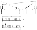
Вся сфера РсЛС может быть разделена на две, а именно на Стационарную Радиосвязную Локальную Сеть (СРсЛС) и Мобильную Радиосвязанную Локальную Сеть (МРсЛС). Такое разделение иллюстрируется на фиг. 2 и 3, соответственно. The entire area of the Radar can be divided into two, namely, the Stationary Radiocommunication Local Area Network (SRsLS) and the Mobile Radiocommunication Local Area Network (MRsLS). Such a separation is illustrated in FIG. 2 and 3, respectively.
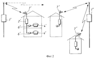
На фиг. 2 показана схема СРсЛС. В этом случае телефонный абонент имеет одно или более телефонных гнезд 6', к которым подключаются телефонные аппараты 4'. Здесь для абонента нет никаких отличий от ПЛС. Телефонные аппараты 4' подключаются к гнездам 6', которые соединены с так называемой Абонентской Стационарной Станцией (АСС) 2', чьи выходы подключены к антенне 7', установленной на крыше здания или иным образом снаружи его. Через эти антенны осуществляется радиосвязь с Базовыми Станциями 1' и 1''. Пунктирная стрелка на рисунке указывает на то, что имеются некоторые взаимные помехи между базовыми станциями. До настоящего времени идея СРсЛС реализована в весьма ограниченных масштабах. Радиоканалы связи или специальная техника радиосвязи использовались для связи с изолированными островами или удаленными сельскими пунктами и т.п. Позднее системы типа СРсЛС, построенные на базе существующих аналоговых сотовых систем, использовались в странах со слабо развитой сетью проводной общественной связи. Один из примеров описан в брошюре N LZT120217, "Система с радиодоступом PAS 1000", выпущенная фирмой "Эрикссон". В ней описаны системы, предназначенные для использования в условиях с ограничением времени, поскольку основные случаи применения потребуют эффективного кодирования для высококачественной передачи речевого сигнала и услуг службы ISDN (Цифровой сети с комплексными услугами). Главным преимуществом средств СРсЛС является их экономичность как по частоте, так и по мощности вследствие того, что направленные антенны могут быть установлены на крышах зданий абонентов. При этом, например, усиление в антенном тракте в 15 дБ дает развязку между передней и задней полусферами порядка 20-30 дБ, что при использовании тех же элементов дает 10-ти кратное повышение частотной эффективности по сравнению с Мобильными Радиосвязанными Локальными Сетями (МРсЛС), которые будут рассмотрены ниже. Такая частотная эффективность является решающим фактором для обеспечения повышенной скорости передачи бит, необходимой как для высокого качества передачи речи, так и для Цифровой сети с комплексными услугами. Направленные антенны также уменьшают потенциальную опасность снижения качества ввиду временной дисперсии. Серьезным недостатком СРсЛС, однако, является то, что пользователь лишен тех преимуществ, которые дает мобильная связь. In FIG. 2 shows a scheme SRSLS. In this case, the telephone subscriber has one or more telephone jacks 6 'to which the telephone sets 4' are connected. Here for the subscriber there are no differences from the PLC. Telephone sets 4 'are connected to the sockets 6', which are connected to the so-called Subscriber Station Station (ACC) 2 ', whose outputs are connected to the antenna 7', mounted on the roof of the building or otherwise outside it. Through these antennas, radio communication is made with Base Stations 1 'and 1' '. The dotted arrow in the figure indicates that there is some mutual interference between the base stations. To date, the idea of SRSLS implemented on a very limited scale. Radio channels or special radio technology were used to communicate with isolated islands or remote rural areas, etc. Later, systems such as SRsLS built on the basis of existing analog cellular systems were used in countries with a poorly developed network of wired public communications. One example is described in brochure N LZT120217, "PAS 1000 Radio Access System", issued by Ericsson. It describes systems designed for use in time-limited conditions, since the main applications will require efficient coding for high-quality voice transmission and ISDN (Digital Network with Integrated Services) services. The main advantage of SRSLS means is their efficiency both in frequency and power due to the fact that directional antennas can be installed on the roofs of subscribers' buildings. At the same time, for example, an amplification in the antenna path of 15 dB gives a decoupling between the front and rear hemispheres of the order of 20-30 dB, which, when using the same elements, gives a 10-fold increase in frequency efficiency compared to Mobile Radio Local Area Networks (MRLS), which will be discussed below. Such frequency efficiency is a decisive factor for ensuring the increased bit rate, which is necessary both for high quality voice transmission, and for a digital network with complex services. Directional antennas also reduce the potential for quality degradation due to temporal dispersion. A serious drawback of SRSLS, however, is that the user is deprived of the advantages provided by mobile communications.
Мобильность обеспечивается средствами МРсЛС и является преимуществом такой локальной сети. Однако, она имеет и недостатки, т.к. инфраструктура радиосвязи не обеспечивает достаточно высокой частотной эффективности и требует использования очень дорогих базовых станций, что обусловлено ограничениями в дальности связи. Причиной этого является необходимость обеспечения надежной радиосвязи в любой части здания независимо от использованных строительных материалов, вида подвальных этажей, топографии, временного нахождения портативного телефона в различных местах и т.п. Все это требует значительных трудовых и финансовых затрат. Кроме того, у пользователя отсутствуют средства усиления сигналов в антенном тракте, а мобильные средства связи не обладают высокой мощностью. Это приводит к тому, что потери на распространение радиоволн достигают 40 дБ по сравнению со средствами СРсЛС. Такая величина потерь при модели распространения D4 приводит к 100-крратному увеличению количества базовых станций по сравнению с СРсЛС, если мощность излучения остается той же самой (особенно в наихудшем случае десятикратного уменьшения дальности). Кроме этого, как указывалось выше, в некоторых странах административные постановления не допускают мобильности телефонных операторов. Поэтому в настоящее время структуры СРсЛС существуют только в виде испытательных систем, не нашедших коммерческой реализации. Они описаны в статье "Универсальные цифровые портативные средства связи". Перспективы прикладных исследований", ICC '86, Торонто, Канада, Июнь 22-25, 1986 г., авторы Д.С. Кокс и др.Mobility is provided by MRLS means and is an advantage of such a local network. However, it also has drawbacks, as the radio communication infrastructure does not provide a sufficiently high frequency efficiency and requires the use of very expensive base stations, due to limitations in the communication range. The reason for this is the need to ensure reliable radio communications in any part of the building, regardless of the building materials used, the type of basement floors, topography, temporary location of the portable phone in various places, etc. All this requires significant labor and financial costs. In addition, the user has no means of amplifying signals in the antenna path, and mobile communications do not have high power. This leads to the fact that losses on the propagation of radio waves reach 40 dB compared with the means of radar. Such a magnitude of losses in the propagation model D 4 leads to a 100-fold increase in the number of base stations compared to SRSLS if the radiation power remains the same (especially in the worst case of a tenfold decrease in range). In addition, as mentioned above, in some countries administrative regulations do not allow the mobility of telephone operators. Therefore, at present, the structures of SRLSLS exist only in the form of test systems that have not found commercial implementation. They are described in the article "Universal Digital Portable Communications". Prospects for Applied Research, ICC '86, Toronto, Canada, June 22-25, 1986, authors D.S. Cox et al.
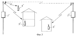
Структура МРсЛС схематически показана на фиг. 3. Здесь абонентские мобильные станции (АМС) 5' (портативные телефоны) напрямую связаны по радио с базовыми станциями 1', 1'', причем эта прямая связь относится как к внутренним (в здании) средствам, так и к внешним. Длинная пунктирная стрелка указывает на наличие высокого уровня взаимных помех между базовыми станциями. The structure of the MRLS is shown schematically in FIG. 3. Here, subscriber mobile stations (AMS) 5 '(portable telephones) are directly connected by radio to base stations 1', 1 '', and this direct connection applies both to internal (in the building) facilities and to external ones. A long dotted arrow indicates a high level of interference between base stations.
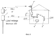
При желании мобильность связи может быть обеспечена в пределах здания, где имеются нормальные средства ПЛС или СРсЛС, путем приобретения и использования стандартных беспроводных телефонных аппаратов, что иллюстрируется на фиг. 4, где стационарный беспроводной блок (CFP) подключен к абонентскому гнезду (розетке) 9. Этот блок может поддерживать связь с беспроводным портативным блоком (CPP). Однако беспроводный телефон не является частью базовой локальной сети, а представляет собой лишь частным образом создаваемые технические приспособления. Кроме этого, две отдельные радиосистемы должны включаться последовательно, что вызывает излишнюю задержку речевого сигнала, а также дополнительные финансовые затраты. И, наконец, если в беспроводном телефоне используется цифровой передаваемый сигнал, то неизбежно двойное цифровое кодирование/декодирование речи. Значительные ограничения также накладываются на мобильные средства связи необходимостью использования различных полос частот для частной и общественной связи. If desired, communication mobility can be provided within the building, where there are normal means of PLC or SRSLS, by acquiring and using standard wireless telephones, as illustrated in FIG. 4, where a fixed wireless unit (CFP) is connected to a subscriber jack (socket) 9. This unit can communicate with a wireless portable unit (CPP). However, the cordless telephone is not part of the core LAN, but is only privately created technical devices. In addition, two separate radio systems must be switched on sequentially, which causes excessive delay of the speech signal, as well as additional financial costs. And finally, if a digital telephone is used in a cordless telephone, then digital speech encoding / decoding is inevitable. Significant restrictions are also imposed on mobile communications by the need to use different frequency bands for private and public communications.
Сущность изобретения
Целью настоящего изобретения является разрешение ранее упомянутых проблем путем создания устройства, которое было бы надежным в работе, недорогим, обладало бы частотной эффективностью и в то же время было бы мобильным. Кроме того, это устройство должно обеспечивать высокое качество речевой связи и обладать теми же показателями в обслуживании, что и проводные средства, т. е. настоящее изобретение должно соединять в себе преимущества СРсЛС и МРсЛС. Еще одна цель изобретения заключается в обеспечении частотно-эффективной радиосвязи между базовыми станциями и портативными средствами внутри или вне учреждения или офиса. Далее, целью изобретения является также создание эффективного и недорогого устройства для внутренней связи между портативными средствами в пределах учреждения или офиса, которые в дальнейшем будем называть просто зданием. Кроме этого, настоящее изобретение должно обеспечивать возможность регистрации внутренних радиосообщений по частотной лицензии, например, в тех случаях, когда телефонному оператору не разрешается пользование мобильными средствами, как упоминалось выше в отношении некоторых стран. Но в то же время одной из целей настоящего изобретения является обеспечение высокой степени мобильности. И, наконец, еще одной целью изобретения является использование одной и той же полосы частот как для частной, так и общественной связи.SUMMARY OF THE INVENTION
The aim of the present invention is to solve the previously mentioned problems by creating a device that would be reliable in operation, inexpensive, would have frequency efficiency and at the same time would be mobile. In addition, this device should provide high quality voice communications and have the same performance in service as wired tools, i.e., the present invention should combine the advantages of SRSLS and MRSLS. Another objective of the invention is to provide frequency-effective radio communications between base stations and portable means, inside or outside an institution or office. Further, the aim of the invention is also the creation of an effective and inexpensive device for intercom between portable means within an institution or office, which in the future will be called simply a building. In addition, the present invention should provide the possibility of registering internal radio communications under a frequency license, for example, in cases where the telephone operator is not allowed to use mobile means, as mentioned above in relation to some countries. But at the same time, one of the objectives of the present invention is to provide a high degree of mobility. And finally, another objective of the invention is the use of the same frequency band for both private and public communications.
Эти и другие цели настоящего изобретения достигаются с помощью устройства, характеризуемого признаками, изложенными в отличительной части пункта 1 формулы изобретения. These and other objectives of the present invention are achieved using a device characterized by the features set forth in the characterizing part of
Прочие цели и преимущества настоящего изобретения будут более понятны из приводимого ниже подробного описания. Так, например, в преимущественном варианте изобретения удается избежать предварительного распределения частот благодаря децентрализованному динамическому распределению каналов. Other objectives and advantages of the present invention will be better understood from the following detailed description. Thus, for example, in an advantageous embodiment of the invention, pre-allocation of frequencies is avoided due to the decentralized dynamic allocation of channels.
Согласно настоящему изобретению, так называемая Абонентская Стационарная Станция АСС, показанная на фиг. 2, усовершенствована до уровня простой Абонентской Стационарной Станции с Многостанционным доступом (АССМД) и представляет собой средство радиообмена, обеспечивающее радиосвязь между базовыми станциями и портативными абонентскими мобильными станциями внутри или вне здания, а также между отдельными абонентскими станциями. Благодаря тому факту, что согласно настоящему изобретению в одном общем приемопередатчике применен радио переключатель, задержка речевого сигнала здесь значительно уменьшена по сравнению со случаем, когда две отдельные системы включаются последовательно. Согласно предпочтительному варианту настоящего изобретения абонентская станция может установить связь не только с АССМД, но и прямую связь с базовой станцией в пределах ее досягаемости. According to the present invention, the so-called ACC Subscriber Station Station shown in FIG. 2, has been upgraded to the level of a simple Subscriber Station Station with Multiple Access (ASMD) and is a radio exchange tool that provides radio communication between base stations and portable subscriber mobile stations inside or outside the building, as well as between individual subscriber stations. Due to the fact that according to the present invention, a radio switch is used in one common transceiver, the delay of the speech signal is significantly reduced compared with the case when two separate systems are connected in series. According to a preferred embodiment of the present invention, the subscriber station can establish communication not only with ASMD, but also direct communication with the base station within its reach.
Также в предпочтительном варианте изобретения использована так называемая техника Многостанционного Доступа с Временным Разделением при использовании Множества Несущих и Дуплексного Режима с Временным Разделением, когда применяется непрерывное или мгновенное динамическое распределение каналов. Этот метод описан в работе "новые принципы радиодоступа в мобильных радиосистемах третьего поколения" из числа материалов Международного Симпозиума IEEE по вопросам Персональных, Внутренних и Мобильных Средств Радиосвязи, Октябрь 19-21, 1992 г., авторы Д.Акерберг и фирма "Эриксон Радио Системз АВ" (настоящий заявитель). В этой работе (далее в описании - ссылка А) описана Непрерывная Динамическая Селекция Каналов (НДСК), означающая, что станция или переключатель выбирают канал с наилучшими показателями (на момент выбора) из общего набора каналов, который предназначен для всех абонентов во всех зданиях. С помощью такой техники удается избежать предварительного распределения частот для базовых станций или для отдельных абонентов. Also in a preferred embodiment of the invention, the so-called Time Division Multiple Access technique is used when using the Multiple Carriers and Time Division Multiplexing when continuous or instantaneous dynamic channel allocation is used. This method is described in the paper “New Principles of Radio Access in Third Generation Mobile Radio Systems” from the materials of the IEEE International Symposium on Personal, Internal and Mobile Radiocommunication Facilities, October 19-21, 1992, authors D. Akerberg and Ericsson Radio Systems AB "(the present applicant). In this work (hereinafter referred to as link A), Continuous Dynamic Channel Selection (SSC) is described, which means that the station or switch selects the channel with the best performance (at the time of selection) from the common set of channels, which is intended for all subscribers in all buildings. Using this technique, it is possible to avoid preliminary frequency allocation for base stations or for individual subscribers.
В пункте 26 формулы заявляется конкретный вариант изобретения, относящийся к системе, содержащей базовую и мобильную станции, в которой используется многостанционный радиодоступ в дуплексном режиме с временным разделением, а также динамическое распределение каналов управляемым переключением от портативных средств. Здесь возможны расширение зоны уверенного приема и объема радиообмена в составе подобной сотовой системы путем ввода беспроводной базовой станции. Беспроводные системы, построенные на основе упомянутой выше технологии, могут обеспечить расширенную зону уверенного приема при установке проводных базовых станций, которые могут обслуживать большое количество мобильных станций. Такие системы имеют различный масштаб - от Макро-ячеек для обширного внешнего пространства до микро- и пико-ячеек для пользования внутри здания при большой насыщенности аппаратурой. В настоящее время возрастает интерес к использованию рассмотренных выше методов для служб персональной беспроводной связи и для замены проводных средств в локальных сетях. В этой сфере размеры зоны, охваченной телефонной сетью, все еще зависят от планирования и установки проводных средств связи. Поэтому вполне понятно намерение расширить размеры зоны охвата путем добавления беспроводных базовых станций. Такая сеть могла бы стать очень гибкой и позволяла бы эффективно планировать развитие зоны охвата. Кроме того, это позволило бы использовать локальную мобильность и возможности радиообмена для обработки локальных вызовов.
Данный вариант изобретения больше подходит к системам, построенным на основе использования методов Многостанционного Доступа с Временным Разделением (МДВР - TDMA) с Динамическим Распределением Каналов (ДРК - DCA) и с переключениями, управляемыми портативными средствами, т.е. отвечающим требованиям стандарта Цифровой Европейской Беспроводной Связи (ЦЕБС - DECT) ET 300175. Этот стандарт предусматривает применение методов МД/МДВР/ДВР с использованием десяти несущих частот в 12-ти дуплексных каналах при времени кадрового цикла 10 мс. This embodiment of the invention is more suitable for systems based on the use of Time Division Multiple Access (TDMA) methods with Dynamic Channel Allocation (DCA) and with handheld-controlled switching, i.e. complying with the requirements of the Digital European Wireless Communication Standard (CEBS - DECT) ET 300175. This standard provides for the application of MD / TDMA / DVR methods using ten carrier frequencies in 12 duplex channels with a frame cycle time of 10 ms.
Данный вариант изобретения в системах, соответствующих стандарту ЦЕБС, мог бы позволить получать одновременный доступ к проводным и беспроводным базовым станциям при такой синхронизации кадров и дуплексе с временным разделением (ДВР - TDD), чтобы передача по спутниковой линии связи велась в одни и те же половины кадров. Такая синхронизация кадров базовых станций в одной такой системе необходима для обеспечения условий поиска и переключений между базовыми станциями. This embodiment of the invention in systems compliant with the CEBS standard could allow simultaneous access to wired and wireless base stations with such frame synchronization and time division duplex (TDD), so that the transmission over the satellite communication line is carried out in the same halves frames. Such synchronization of frames of base stations in one such system is necessary to provide search conditions and switching between base stations.
С применением данного варианта настоящего изобретения беспроводная базовая станция становится совместимой со стандартными проводными базовыми станциями и беспроводными терминалами, а также получает способность отвечать тем же требованиям, что и проводная базовая станция, в результате чего для терминала исчезает разница между беспроводной и проводной базовой станцией. Беспроводная базовая станция может также обеспечить коммутацию вызовов в локальном масштабе вследствие ее МДВР-архитектуры и расширить объем радиообмена всей беспроводной сети с точки зрения пользователя. Using this embodiment of the present invention, the wireless base station becomes compatible with standard wired base stations and wireless terminals, and also gets the ability to meet the same requirements as the wired base station, as a result of which the difference between the wireless and wired base station disappears for the terminal. A wireless base station can also provide local call switching due to its TDMA architecture and expand the wireless exchange of the entire wireless network from the user's point of view.
В формуле настоящего изобретения заявлены и другие примеры осуществления изобретения. Other exemplary embodiments are claimed in the claims.
Краткое описание чертежей
Далее настоящее изобретение описывается со ссылкой на прилагаемые чертежи, которые следует рассматривать лишь как иллюстрации одного из примеров реализации настоящего изобретения, не ограничивающих всего объема притязаний.Brief Description of the Drawings
Further, the present invention is described with reference to the accompanying drawings, which should be considered only as illustrations of one example of the implementation of the present invention, not limiting the entire scope of the claims.
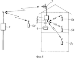
Фиг. 5 - вторая станция, связывающая мобильные станции абонента и базовую станцию. FIG. 5 - the second station connecting the mobile stations of the subscriber and the base station.
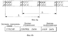
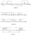
Фиг. 6a - кадр в системе МДВР, содержащей 12 дуплексных каналов. FIG. 6a is a frame in a TDMA system containing 12 duplex channels.
Фиг. 6b - пример данных, передаваемых во временном интервале, когда группа "контрольные данные" регулярно содержит информацию об идентификации прав доступа. FIG. 6b is an example of data transmitted in a time interval when the “control data” group regularly contains information on identifying access rights.
Фиг. 7 - одиночная радиоустановка с МДВР, использующая различные временные интервалы для различных одновременных соединений. FIG. 7 - a single radio installation with mdvr using different time intervals for various simultaneous connections.
Фиг. 8 - синхронизация временных интервалов и поток информации в радиоустановке с МДВР. FIG. 8 - synchronization of time intervals and the flow of information in a radio installation with TDMA.
Фиг. 9 - иллюстрация функций внутренней связи АСС с множественным (многостанционным) доступом. FIG. 9 is an illustration of the ACC intercom functions with multiple (multi-station) access.
Фиг. 10a - полосы частот для устройства с МДВР и дуплексным режимом с частотным Разделением (ДЧР). FIG. 10a — frequency bands for a device with TDMA and full duplex frequency division multiplexing (HDF).
Фиг. 10b - сдвиг интервалов приема и передачи в системе, соответствующей представленному на фиг. 10a. FIG. 10b is a shift of the reception and transmission intervals in the system corresponding to that shown in FIG. 10a.
Фиг. 10c - иллюстрация чередования в Дуплексном режиме с Разделением Времени (ДРВ). FIG. 10c is an illustration of the alternation in Duplex Mode with Time Division (DRV).
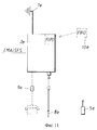
Фиг. 11 - устройство с частным мобильным средством связи. FIG. 11 is a device with a private mobile communications tool.
Фиг. 12 - иллюстрация синхронизации базовых станций. FIG. 12 is an illustration of base station synchronization.
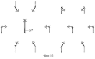
Фиг. 13 - схематическая иллюстрация синхронизации всей сети. FIG. 13 is a schematic illustration of synchronization of an entire network.
Фиг. 14 - блок-схема базовой станции (БС). FIG. 14 is a block diagram of a base station (BS).
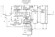
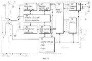
Фиг. 15 - блок-схема МДАСС в режиме радиообмена. FIG. 15 is a block diagram of MDASS in radio mode.
Фиг. 16 - блок-схема Абонентской мобильной Станции (АМС). FIG. 16 is a block diagram of a Subscriber Mobile Station (AMC).
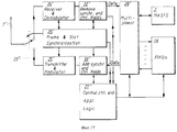
Фиг. 17 - дополнительная АСС, соединенная с МДАСС. FIG. 17 - additional ACC connected to MDASS.
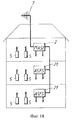
Фиг. 18 - схематическая иллюстрация двух дополнительных АСС, соединенных с МДАСС. FIG. 18 is a schematic illustration of two additional ACCs connected to MDASS.
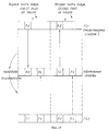
Фиг. 19 - иллюстрация переключения мобильной станции с первой стационарной станции на вторую. FIG. 19 is an illustration of switching a mobile station from a first fixed station to a second.
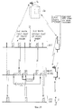
Фиг. 20 - вариант изобретения с распределением интервалов времени МДАСС, которая отвечает конкретным требованиям к порядку переключений. FIG. 20 is a variant of the invention with a distribution of time intervals MDASS, which meets the specific requirements for the order of switching.
Подробное описание изобретения
На фиг. 5 показано устройство, содержащее базовую станцию 1, вторую станцию 2, представляющую собой дешевую одиночную абонентскую радиостанцию, и четыре абонентских мобильных станции или мобильных блока 5a, 5b, 5c, 5d (АМС). Абонентская станция 2, представляющая в данном случае упоминавшуюся выше МДАСС, содержит такое средство общественной связи, как установленную на крыше антенну 7 для связи с базовой станцией 1. Три АМС 5a-5c расположены либо внутри здания, либо вблизи него и соединены с АСС 2, которая, как указано выше, есть МДАСС, через внешнюю антенну или через антенну ближней связи 8 и антенны, имеющиеся на каждой АМС 5a-5c. Если МДАСС переключает линию общественной связи, сформированную через антенну на крыше 7, на локальное соединение, включающее АМС 5 через внутреннюю антенну 8, то обеспечивается мобильность связи. Если обеспечивается соединение между двумя сформированными локальными линиями (через внутреннюю антенну), имеются еще и внутренние соединения, то реализуются и функции внутренней связи. При рассмотрении фиг. 9 будет описано, каким образом это осуществляется с помощью одиночной МДВР АМС. Имеется также возможность присвоить абонентской станции 5d дополнительное право прямого доступа к базовой станции 1 или даже к общей сети базовых станций в составе СРсЛС. Этим может быть достигнута еще большая степень мобильности.DETAILED DESCRIPTION OF THE INVENTION
In FIG. 5 shows a device comprising a
Вторая станция 2 может быть, кроме того, снабжена стандартным (двухприводным) интерфейсом в виде розетки 9 (соединение обозначено пунктирной линией). На фиг. 5 показана только одна вторая станция 2, хотя таких станций может быть, конечно, несколько. Антенна ближней связи 8 может быть всенаправленной, хотя это и не обязательно. The
Основная идея в данном случае заключается в использовании системы СРсЛС совместно с техникой временного разделения множества радиосредств (МДВР). Наибольшими преимуществами обладает дуплексный режим работы с разделением во времени (МДВР/ДВР), иллюстрируемый на фиг. 6a, где показан так называемый МДВР кадр, содержащий 12 приемных и 12 передающих интервалов времени при работе на 12-ти дуплексных каналах. Вполне понятно, конечно, что соотношение количества временных интервалов приема и передачи может быть различным. Согласно одному из вариантов настоящего изобретения соответствующее устройство используется применительно к стандарту ЦЕБС (ЕСТ), предусматривающему 12х12 временных интервалов. В системах ЦЕБС период (цикл) кадра TF составляет 10 мс (см. ссылку А). Литерами T и R на рисунке обозначены интервалы передачи и приема соответственно, а цифрами обозначены взаимосвязанные интервалы дуплексной связи. Однако, как правило, типовой цикл МДВР-кадров имеет величину 10 мс.The main idea in this case is to use the SRSLS system in conjunction with the technique of temporary separation of multiple radio devices (TDMA). The greatest advantages are the time division duplex (TDMA / DVR) mode of operation illustrated in FIG. 6a, where the so-called TDMA frame is shown, containing 12 receiving and 12 transmitting time intervals when operating on 12 duplex channels. It is quite understandable, of course, that the ratio of the number of time intervals for reception and transmission can be different. According to one of the variants of the present invention, the corresponding device is used in relation to the CEBS standard (ECT), providing for 12x12 time intervals. In CEBS systems, the period (cycle) of the frame T F is 10 ms (see reference A). The letters T and R in the figure indicate the transmission and reception intervals, respectively, and the numbers indicate the interconnected duplex communication intervals. However, as a rule, a typical cycle of mdvr frames has a value of 10 ms.
Типовая структура временного интервала показана на фиг. 6b. Контрольные данные регулярно содержат мультиплексированную информацию об идентификации и праве доступа, опорные сигналы синхронизации, служебную информацию и т.п. В контрольном канале выполняются также операции поиска и формирования вызова, что более подробно описано в ссылке А, упоминавшейся ранее. Типовой речевой кодер-декодер (кодек) представляет собой устройство адаптивной дифференциальной импульсно-кодовой модуляции, рассчитанное на 32 Кбит. Это означает, что при каждом речевом вызове должно передаваться и приниматься 320 бит в течение каждого кадра (T = 10 мс), т.е. объем речевой информации у пользователя должен составлять 320 бит. Объем контрольных данных обычно составляет 64 бит и 32 бита требуют сигналы синхронизации. С учетом защитного интервала общее количество бит во временном интервале может доходить до 480 бит. Если кадр содержит 12 интервалов приема и 12 интервалов передачи, то скорость передачи составит 480х24х100 бит в секунду, т.е. 1152 Кбит/с. A typical time slot structure is shown in FIG. 6b. The control data regularly contains multiplexed identification and access right information, synchronization reference signals, service information, etc. Search and call generation operations are also performed in the control channel, which is described in more detail in link A mentioned earlier. A typical speech codec-decoder (codec) is an adaptive differential pulse-code modulation device designed for 32 Kbps. This means that for each voice call, 320 bits should be transmitted and received during each frame (T = 10 ms), i.e. the amount of voice information the user should be 320 bits. The amount of control data is usually 64 bits and 32 bits require synchronization signals. Given the guard interval, the total number of bits in a time slot may be up to 480 bits. If the frame contains 12 reception intervals and 12 transmission intervals, then the transmission rate will be 480x24x100 bits per second, i.e. 1152 Kbps
Согласно настоящему варианту в системе используется несколько несущих частот. Это могут быть 10 частот с разносом по диапазону через 1,0-1,8 МГц в зависимости от метода модуляции. Одним из примеров может служить система согласно стандарту ЦЕБС. В ссылке А описано, каким образом осуществляется динамическая селекция каналов. Эти вопросы освещаются также в материалах, относящихся к различным электронным телефонным системам (ETSI): "Радиооборудование и Системы (RES): Общий Интерфейс ЦЕБС, ETP 300175-1; 3000175-9; ETSI, "Справочные документы ЦЕБС, ETP 015; ETSI, "Радиооборудование и Системы (RES): Технические характеристики и требования к службам и установкам общего интерфейса ЦЕБС, ETP 043; и ETSI "Радиооборудование и Системы: Справочник ЦЕБС по характеристикам, влияющим на объем радиообмена, и руководство по обслуживанию радиолиний с высоким качеством передачи, включая результаты моделирования", ETP 042. Что же касается варианта устройства с использованием множества несущих частот (МН) и методов МДВР/ДВП, то для обеспечения достаточного количества каналов (комбинаций частота/временной интервал) базовая станция (БС) и АССМД 2 могут быть также выполнены в виде одиночных приемопередатчиков, обладающих способностью изменения несущей в защитной полосе между рабочими временными интервалами, что более подробно описывается в качестве стандартной концепции базовых станций в ссылке А и в патенте Швеции N E-B-466279. В этих материалах показано, что АССМД 2 (а также портативные абонентские станции 5) могут иметь доступ ко множеству каналов с помощью всего лишь одной радиоустановки. According to the present embodiment, several carrier frequencies are used in the system. It can be 10 frequencies with a span across 1.0-1.8 MHz depending on the modulation method. One example is a system according to the CEBS standard. Link A describes how dynamic channel selection is performed. These issues are also covered in materials related to various electronic telephone systems (ETSI): "Radio Equipment and Systems (RES): CEBS Common Interface, ETP 300175-1; 3000175-9; ETSI," CEBS Reference Documents, ETP 015; ETSI, "Radio Equipment and Systems (RES): Technical Specifications and Requirements for Services and Settings for the Common CEBS Interface, ETP 043; and ETSI" Radio Equipment and Systems: CEBS Manual on Features Affecting the Volume of Radio Communication, and High Quality Radio Service Manual transmissions, including simulation results, "ETP 042. As for the variant of the device using multiple carrier frequencies (MH) and TDMA / fiberboard methods, to ensure a sufficient number of channels (frequency / time interval combinations) of the bases I station (BS) and
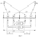
Возвращаясь к изображенной на фиг. 5 станции 2, отметим, что она содержит так называемую Абонентскую Стационарную станцию Множественного (Многостанционного) Доступа (АССМД) и соединена с двумя антеннами 7 и 8, работающими раздельно во времени. Наружная (на крыше) антенна 7 согласно одному из вариантов устройства имеет направленное усиление (например, 10-18 дБ), обеспечивающее большую дальность действия, и направлена на ближайшую базовую станцию 1, тогда как внутренняя антенна 8 малого радиуса действия не имеет такого усиления. Метод МДВР предоставляет возможность для АСС 2 одновременно устанавливать несколько информационных контактов с одной радиоустановки путем использования разных временных интервалов для различных контактов, что показано на фиг. 7, иллюстрирующем работу внутреннего переговорного устройства (интеркома). Здесь одно МДВР средство радиосвязи выполняет функции недорогого одиночного радиопереключателя, а именно переключатель внутренней связи образуется просто путем сдвига данных, получаемых пользователем от первой абонентской станции 5f в течение одного из приемных временных интервалов, например, в интервале R4, в интервал передачи T7, который используется второй абонентской станцией 5b. Такой сдвиг выполняется, например, цифровым ЗУ типа FIFO (хранящим и выдающим данные в порядке поступления, или по так называемому правилу "первым вошел - первым вышел"), в котором выходной сигнал интервала R4 задерживается с тем, чтобы попасть в желаемый интервал передачи T7. (На рисунках интервалы приема обозначены литерой R, а интервалы передачи - литерой T, и в обоих случаях - соответствующим номером). Returning to FIG. 5
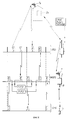
Далее, на фиг. 8 показана АССМД 2, установившая контакт с общественной сетью через внешнюю антенну 7 и базовую станцию 1, входящую в состав СРсЛС, используя пару временных интервалов 7, и в то же самое время поддерживающая связь с АМС 5 через внутреннюю антенну 8, используя для этого пару временных интервалов 1. Базовая станция 1 может, в свою очередь, также устанавливать контакт, например, с другой АСС 2a, показанной на рисунке пунктиром, которая также снабжена внешней антенной дальнего действия 7a, использующей в этом случае пару временных интервалов 3. Данный рисунок служит также иллюстрацией синхронизации временных интервалов при методе МДВР и потока информации по радио между базовой станцией 1, АССМД 2 и АМС 5. Базовая станция 1 соединена проводами с местной общественной АТС. Как будет показано ниже при расмотрении фиг. 14, речевой сигнал от АТС общего пользования кодируется и мультиплексируется с формированием МДВР/ДВР кадра на базовой станции 1. Кроме того, как будет показано при рассмотрении фиг. 15, АССМД 2 устанавливает внутреннее соединение сети общего пользования, доступ к которой осуществляется в паре интервалов 7, с частной портативной АМС 5 в паре интервалов 1. Внутренние соединения АССМД осуществляются с помощью уже упоминавшихся так называемых ЗУ типа FIFO (см. описание фиг. 7). Синхронизация будет рассмотрена ниже. Further, in FIG. Figure 8 shows an
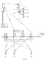
На фиг. 9 иллюстрируются два вызова через АСС или АССМД 2. Первое телефонное соединение устанавливается между базовой станцией 1 и абонентской станцией или портативной АМС 5a, а второе - между абонентскими станциями 5b и 5c, т. е. между двумя портативными АМС 5b и АМС 5c. Если через антенну 7 частная портативная станция 5a устанавливает связь с сетью общего пользования, то этим обеспечивается мобильность связи. Если к тому же устанавливается связь между двумя частными абонентскими портативными станциями 5b и 5c, то обеспечиваются и функции внутреннего переговорного устройства (интеркома). In FIG. 9 illustrates two calls via ACC or
В варианте согласно фиг. 9 проводные линии связывают местную АТС общего пользования с базовой станцией 1. In the embodiment of FIG. 9 wire lines connect the local public switched telephone exchange with
Следует отметить, что при использовании ЗУ типа FIFO, подробно описанных при рассмотрении фиг. 7, никакой дополнительной обработки речевой информации не производится и потому никакого нарушения речи и иного влияния на нее не происходит. Кодирование речи имеет место только в базовой станции 1 и в абонентской АМС 5. Однако, здесь вводится задержка, равная удвоенному времени распространения радиоволн, которое добавляется к TF (периоду следования кадров МДВР). Из фиг. 7 можно видеть, что дополнительная задержка при распространении в обе стороны есть TA + TB = 0,5 TF - T1 + 0,5 TF + T1 = TF.It should be noted that when using FIFO type memory devices described in detail in connection with FIG. 7, no additional processing of speech information is performed, and therefore no speech disturbance and other influence on it occurs. Speech coding takes place only in
Базовые станции в системе СРсЛС нормальным образом передают особую информацию об идентификации прав доступа к общественной сети (см. ссылку А). Доступ же к этим БС СРсЛС имеют только АСС или АМС, имеющие такие же права доступа к общественной сети. Станция АССМД 2 через внутреннюю антенну 8 передает особый ключ к правам доступа. И только абонентские станции или мобильные АМС 5, обладающие тем же самым ключом на праве доступа, могут связываться с АССМД 2 и быть готовыми к приему или посылке вызова на связь. АМС 5 может быть снабжена как ключом на право частного, так и на право общественного доступа, что обеспечивает абоненту мобильность не только внутри или вокруг его здания, но везде, где он находится в пределах достягаемости БС системы СРсЛС. Возвращаясь к фиг. 8, отметим, что временные интервалы T3, T7, R3, R7 используются для установления контакта с общественной сетью, а интервалы R1, T1 отведены для частных контактов. The base stations in the SRSLS system normally transmit specific information about the identification of access rights to the public network (see link A). Access to these BS SRLSLSs is available only to the ACC or AMC, which have the same access rights to the public network. The
Это дает возможность использовать общую полосу частот как для частной, так и для общественной связи, но позволяет также работать в разных, обычно смежных, полосах частот. This makes it possible to use a common frequency band for both private and public communications, but also allows you to work in different, usually adjacent, frequency bands.
Если оператору, как упоминалось выше, запрещено работать в мобильном режиме, то АСС абонента может быть снабжена проводным удлинителем к стандартному телефонному гнезду 9e, иллюстрацией чего служит фиг. 11. При этом предполагается, что АСС построена в соответствии со стандартом ЦЕБС (ссылка А), когда в одной и той же полосе частот допускается работа как официально разрешенных средств связи с местной (районной) сетью, так и частных беспроводных (не имеющих официального разрешения) систем в учреждениях и в офисах. В таких системах не требуется предварительного распределения частот по отдельным станциям благодаря динамической селекции каналов, что также описано с приведением различных примеров в ссылке А. Если пользователь желает обеспечить для себя мобильность связи, он может приобрести либо у изготовителя, либо, если это необходимо, у совершенствующих органов власти частные права доступа в качестве фиксированной юридической стороны, внутреннюю антенну 8e, готовую плату 10e для FIFO и мобильную абонентскую станцию (портативный радиотелефон) 5e. Частные права доступа с уникальной идентификацией программируются затем в АССМД 2e и в АМС 5e. При выходе на общественную линию через внешнюю антенну 7e используется уникальный ключ общественного доступа (подтверждающий права доступа); это делается для защиты АМС при связи с БС (не показана), когда используется частный ключ. Таким образом АСС приобретает более высокий уровень возможностей, такой как у АССМД, с дополнением в виде функции частной беспроводной телефонной системы в условиях учреждения или офиса, включая и возможности интеркома, как показано на фиг. 9. If the operator, as mentioned above, is prohibited from working in mobile mode, then the subscriber’s ACC can be equipped with a wired extension cord to a standard telephone jack 9e, as illustrated in FIG. 11. At the same time, it is assumed that the ACC is built in accordance with the CEBS standard (reference A), when both officially authorized means of communication with the local (district) network and private wireless (not having official permission) are allowed to work in the same frequency band ) systems in institutions and offices. In such systems, the preliminary frequency distribution for individual stations is not required due to dynamic channel selection, which is also described with various examples in reference A. If the user wants to ensure the mobility of communication, he can either purchase from the manufacturer or, if necessary, from improving authorities, private access rights as a fixed legal party, an
В вариантах устройства, показанных на фиг. 6-9, где используется метод МДВР с дуплексным режимом ДВР (МДВР/ДВР), настоящее изобретение реализуется наиболее дешевым и эффективным образом. Однако и в других возможных вариантах может использоваться метод МДВР/ДВП; примеры их показаны на фиг. 10a и 10b, где на фиг. 10a по оси абсцисс обозначены полоса частот передачи ППрд и полоса частот приема ППрм, а также обозначен интервал для дуплекса d. На фиг. 10b показаны интервалы передачи T и приема R, причем интервалы приема R (по номерам) смещены относительно интервалов передачи для того, чтобы исключить необходимость применения дуплексных фильтров в портативных или в мобильных абонентских станциях. В этом случае базовая станция ведет прием и передачу одновременно на разных частотах, что увеличивает стоимость станции, и если бы передача и прием не осуществлялись с разносом по времени, как указано на рисунке, то понадобилось бы применение дуплексных фильтров, что является обычной практикой. Однако, поскольку АССМД должна быть достаточно недорогим изделием, прием и передача должны выполняться в разных временных интервалах, что ограничивает количество возможных телефонных соединений до половины имеющихся в наличии интервалов передачи. In the embodiments of the device shown in FIG. 6-9, where the TDMA duplex DVR (TDMA / DVR) method is used, the present invention is implemented in the cheapest and most efficient manner. However, in other possible embodiments, the mdvr / fiberboard method may also be used; examples of them are shown in FIG. 10a and 10b, where in FIG. 10a, the abscissa axis denotes the transmission bandwidth of the transmit Pfrd and the frequency band of reception of the pfd, and also indicates the interval for the duplex d. In FIG. 10b shows transmission intervals T and reception R, wherein reception intervals R (by numbers) are offset from transmission intervals in order to eliminate the need for duplex filters in portable or mobile subscriber stations. In this case, the base station receives and transmits simultaneously at different frequencies, which increases the cost of the station, and if the transmission and reception were not carried out with a time difference, as indicated in the figure, then duplex filters would be necessary, which is common practice. However, since ASMD should be a fairly inexpensive product, reception and transmission must be performed at different time intervals, which limits the number of possible telephone connections to half the available transmission intervals.
В соответствии с альтернативным вариантом устройства возможно применение так называемого режима дуплекса с чередованием (при разделении во времени), схематически показанного на фиг. 10e. According to an alternative embodiment of the device, it is possible to use the so-called alternating duplex mode (in time division), schematically shown in FIG. 10e.
В целях дальнейшей иллюстрации приводятся блок-схемы базовой станции, второй станции (АССМД) и абонентской мобильной станции (АМС), каждая из которых использует режим МС/МДВР/ДВР и 12 пар временных интервалов для передачи в дуплексе. For further illustration, block diagrams of the base station, the second station (ASMD) and the subscriber mobile station (AMC) are presented, each of which uses the MS / TDMA / DVR mode and 12 pairs of time slots for transmission in duplex.
На фиг. 14 представлена блок-схема базовой станции. Она соединена проводами с местной АТС и содержит канал связи, состоящий из множества линий связи, позволяющих устанавливать одновременно 12 телефонных соединений (вызовов). Эти вызовы перекодируются в формат АДИКМ речевыми кодеками 29. В блоке логики центрального управления и распределения 27 обнаруживаются приходящие вызовы и контролируются исходящие вызовы, здесь же выбираются надлежащие комбинации несущих и временных рабочих интервалов, а затем в мультиплексоре 28 группируют различные телефонные соединения или соответствующие рабочие временные интервалы. На фиг. 8 приведен пример выбора базовой станцией временных интервалов 3 и 7 для установления различных телефонных контактов, однако на фиг. 8 и 9 не показана селекция несущих частот. Базовая станция на фиг. 14 содержит блок 26 синхронизации кадров и рабочих интервалов, который осуществляет надлежащее распределение во времени интервалов приема и передачи. Опорные сигналы для такого распределения либо вырабатываются внутри блока, либо извлекаются из сигналов синхронизации, поступающих по проводам от АТС общего пользования; возможно также извлечение таких сигналов через приемник от главной базовой станции, как показано на фиг. 12 и 13. In FIG. 14 is a block diagram of a base station. It is wired to the local telephone exchange and contains a communication channel consisting of many communication lines, allowing you to establish 12 telephone connections (calls) at the same time. These calls are transcoded into the ADPCM format by
Блок логики и управления 27 управляет также работой переключателя 23 Прием/Передача и переключателем 22 множества антенн, если такое их множество применяется. В противном случае в переключателе 22 нет необходимости. При ухудшении качества связи логика управления в первую очередь переводит связь на другую антенну, а если это не помогает, меняет радиоканал. The logic and
На фиг. 15 приведена блок-схема АССМД 2, которая почти идентична блок-схеме базовой станции. Главное различие между ними состоит, во-первых, в том, что АССМД работает на внешнюю направленную антенну и на одну (или две при использовании нескольких антенн) внутреннюю антенну(-ы), во-вторых, в том, что здесь имеется только один речевой кодес 29', который оканчивается 4-х - 2-х-проводной гибридной схемой 35 и стандартным гнездом 36 для стандартного телефонного соединения, в-третьих, наличием ЗУ 16 типа FIFO для переключения радиолиний. Обнаружение и генерация тональных сигналов на средней частоте передачи данных (СЧПД), а также сигналов звонка выполняется в блоке, обозначенном позицией 34. Блок логики и управления 27 подключает внешнюю антенну 22' в те рабочие временные интервалы, которые предназначены для связи с базовой станцией (см. фиг. 8), а также включает внутреннюю антенну в интервалы связи с АМС, как показано на фиг. 8; временные интервалы 7 были выбраны для связи между базовой станцией и АССМД. Приемник АССМД 24' (фиг. 15) привязан к интервалу 17 (фиг. 8), и из поля контрольных данных (фиг. 6b), интервала T7 (фиг. 8), он извлекает опорные сигналы для схемы 26' синхронизации кадров и рабочих интервалов (фиг. 15). In FIG. 15 shows a block diagram of the
АССМД имеет внутренний источник опорных сигналов синхронизации, который используется в случае потери связи с базовой станцией системы СРЛС. ASMD has an internal source of reference synchronization signals, which is used in case of loss of communication with the base station of the radar system.
Часть данных, проходящих в интервалы T7 и R7, может быть переключена на кодек 29' и тем декодирована (фиг. 15), а затем преобразована в стандартные сигналы проводной связи, выводимые через стандартное гнездо 36, или же (в альтернативном варианте) может быть мультиплексирована в FIFO 16 и заново передана с новыми кодами прав доступа (в поле контрольных данных фиг. 6b) на АСС. Интервал 1 на фиг. 7 был выбран для установления связи между АССМД и АМС. Интервалы T7 и R7 содержат идентификаторы прав доступа общего пользования, а интервалы T1 и R1 - частные идентификаторы прав доступа. Для обмена информацией между двумя АМС с использованием интервалов 2 и 6 не требуется ни перемены антенны, ни каких-либо изменений в идентификаторах прав доступа. Данные от этих станций проходят мультиплексор 28' и сдвигаются в FIFO 16, а затем блок логики и управления 27' снова сдвигает данные в мультиплексор в надлежащее время, как показано на фиг. 7. Part of the data passing in the intervals T7 and R7 can be switched to the codec 29 'and thereby decoded (Fig. 15), and then converted to standard wired communication signals output through a
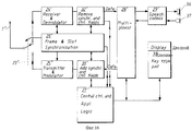
Как можно видеть из блок-схемы на фиг. 16, АМС имеет те же функции, что и АССМД. Она имеет только одну антенну 7'' и только один кодек 29'', подключенный к микрофону 37 и громкоговорителю 36, а также клавиатуру и дисплей 38. Все это само по себе известно, будучи обычной конструкцией портативного беспроводного телефона. Прочие блоки и их функции соответствуют обозначениям на фиг. 15. As can be seen from the flowchart of FIG. 16, AMC has the same functions as ASMD. It has only one 7-inch antenna and only one 29-inch codec, connected to a
При отсутствии активной связи базовая станция может излучать маломощный опознавательный сигнал, содержащий ее идентификаторы прав доступа, а АССМД может также работать в подобном режиме через внутреннюю антенну. В таком режиме АССМД "знает", что она находится в пределах дальности действия базовой станции, а станции АМС "знают", что они в пределах действия АССМД. Подробнее этот опознавательный режим описан в ссылке А. In the absence of active communication, the base station can emit a low-power identification signal containing its access rights identifiers, and the ASMD can also operate in a similar mode through an internal antenna. In this mode, the ASMD “knows” that it is within the range of the base station, and the AMS stations “know” that they are within the operation of the ASMD. This authentication mode is described in more detail in reference A.
В соответствии с еще одним конкретным вариантом реализации настоящего изобретения, который иллюстрируется на фиг. 19 и 20, переключения возможны между АССМД и БС, а также дополнительной АСС (ДАСС) и АССМД, а также другими ДАСС, показанными на фиг. 18. Типовая процедура переключения подробно описана в уже упоминавшейся ссылке А. According to another specific embodiment of the present invention, which is illustrated in FIG. 19 and 20, switching is possible between ASMD and BS, as well as additional ASM (DASM) and ASMD, as well as other DASMs shown in FIG. 18. A typical switching procedure is described in detail in the already mentioned link A.
На фиг. 19 показано, как мобильная станция переключается со связи с первой стационарной станцией на канале 2 на связь со второй стационарной станцией на канале 4. In FIG. 19 shows how a mobile station switches from communication with a first fixed station on
В большинстве систем такие операции, как переключение, требуют, чтобы кадры и рабочие интервалы приема и передачи двух стационарных станций были синхронизированы, как показано на фиг. 19. In most systems, operations such as switching require that the frames and operating intervals of the reception and transmission of two stationary stations be synchronized, as shown in FIG. 19.
Как уже упоминалось выше, портативные радиосредства могут иметь право доступа как к базовым станциям, так и к различным АССМД. Это открывает возможность к выполнению переключения между АССМД и базовой станцией. На фиг. 8 иллюстрируются основные принципы обеспечения мобильности через АССМД, которые, однако, не очень совершенны или оптимальны для операции переключения между БС и АССМД. Как можно видеть из рассмотрения варианта устройства, показанного на фиг. 8, рабочие интервалы обмена между АССМД и АМС не попадают в одну и ту же половину кадра, как это имеет место в случае МС, показанной на фиг. 19, и как это требуется для простоты переключения. As mentioned above, portable radio can have access to both base stations and various ASMDs. This opens up the possibility of switching between ASMD and the base station. In FIG. 8 illustrates the basic principles of mobility through ASMD, which, however, are not very perfect or optimal for the operation of switching between BS and ASMD. As can be seen from consideration of the embodiment of the device shown in FIG. 8, the working exchange intervals between the ASMD and the AMS do not fall into the same half of the frame, as is the case with the MS shown in FIG. 19, and as required for ease of switching.
На фиг. 19 показано первое телефонное соединение со стационарной станцией 1 (FS1), т.е. АССМД использует канал 2. Здесь МС - мобильная станция. Для переключения на стационарную станцию 2 (FS2), например на БС1, используется новый рабочий канал 4. In FIG. 19 shows a first telephone connection to a fixed station 1 (FS1), i.e. ASMD uses
В связи с этим на фиг. 20 приведен альтернативный вариант настоящего изобретения и распределения интервалов работы АССМД, отвечающий требованиям выполнения переключений. Здесь АССМД имеет те же качества и функции, что и станция из фиг. 8, за исключением того, что здесь интервалы передачи для связи с АМС смещены в первую половину кадра, а интервалы приема - во вторую половину кадра. В результате при прямой связи мобильных станций с БС1 и с АССМД интервалы передачи и приема будут синхронизированы в одних и тех же половинах кадров. Благодаря этому упрощаются условия переключения. Дополнительная задержка TF здесь такая же, как и в случае на фиг. 7.In this regard, in FIG. Figure 20 shows an alternative embodiment of the present invention and the allocation of operation intervals of the ASMD that meets the requirements of switching. Here, the ASMD has the same qualities and functions as the station of FIG. 8, except that here the transmission intervals for communication with the AMS are shifted to the first half of the frame, and the reception intervals to the second half of the frame. As a result, with direct communication of mobile stations with BS1 and ASMD, the transmission and reception intervals will be synchronized in the same half frames. This simplifies the switching conditions. The additional delay T F is the same as in the case of FIG. 7.
Для использования в основной сфере применения настоящего изобретения антенны АССМД с малым усилением совсем не обязательно должны быть внутренними, а могут использоваться для обслуживания ближней зоны (охвата ее) и обеспечения функций мобильности. For use in the main scope of the present invention, low-gain AFMD antennas do not need to be internal, but can be used to serve the near field (to cover it) and provide mobility functions.
Ниже приводится подробное описание устройства согласно фиг. 20. Below is a detailed description of the device according to FIG. 20.
Как указывается в ссылке А, базовая станция БС1 всегда активна по крайней мере в одном из каналов связи. Каждый канал связи передает информацию об идентичности БС, об идентификации прав доступа, синхронизации и т.п. Кроме этого, они принимают запросы на вызов. В течение первой половины кадра АССМД слушает передачи от БС 1 во всех рабочих интервалах, которые не используются для передачи от АССМД к АМС, при этом АССМД привязана к одной из активных передач от БС1 и ожидает запросов на установление связи. As indicated in link A, the base station BS1 is always active in at least one of the communication channels. Each communication channel transmits information about the identity of the BS, the identification of access rights, synchronization, etc. In addition, they accept call requests. During the first half of the frame, the ASMD listens to the transmissions from
В течение первого полукадра АССМД ведет также передачу по меньшей мере в одном из интервалов. Это обеспечивает радиовещательной информацией от АССМД все АМС. АССМД действует как базовая станция по отношению к АМС с особым кодом идентификации (не таким, как у БС1) и с особой идентификацией прав доступа. Все АМС в течение первого полукадра привязаны к передачам АССМД. Во втором полукадре АССМД слушает на всех интервалах (которые не используются для передач от АССМД к БС1) в ожидании запросов от АМС. During the first half frame, the ASMD also transmits in at least one of the intervals. This provides broadcast information from ASMD to all AMSs. ASMD acts as a base station with respect to the AMS with a special identification code (not the same as for BS1) and with a special identification of access rights. All AMCs during the first half frame are tied to ASMD transmissions. In the second half frame, the ASMD listens at all intervals (which are not used for transmissions from the ASMD to BS1) while waiting for requests from the AMS.
По отношению к БС1 АССМД действует как мобильная станция, а по отношению к АМС она действует как базовая станция. Подробные сведения о приеме вызова и переключениях приведены в ссылке А. In relation to BS1, the ASMD acts as a mobile station, and in relation to the AMS, it acts as a base station. For details on receiving calls and switching, see link A.
Прием и обработка вызовов, контроль качества работы канала, селекция каналов и внутриячеечные переключения в линиях связи БС 1 - АССМД и АССМД - АМС осуществляются независимо друг от друга. Reception and processing of calls, quality control of the channel, channel selection and intra-cell switching in the communication lines BS 1 - АССМД and АССМД - АМС are carried out independently of each other.
Вследствие независимости этих линий связи данные пользователя (см. фиг. 6b) "прозрачны" для АССМД (т.е. она независима от данных). Поле контрольных данных (фиг. 6b) содержит информацию, общую для различных терминалов, информацию о приеме вызова и установления связи, информацию о качестве связи и о переключениях, уникальную для каждой из двух линий. Таким образом, функции репитера данных пользователя являются только частью присущей АССМД интегральной функциональности в рамках общей концепции. Due to the independence of these communication lines, user data (see FIG. 6b) is “transparent” to the ASMD (i.e., it is data independent). The control data field (Fig. 6b) contains information common to various terminals, information about receiving a call and establishing a connection, information about the quality of communication and switching, unique to each of the two lines. Thus, the functions of the user data repeater are only part of the integrated ASMD integral functionality within the framework of the general concept.
В соответствии с настоящим изобретением базовые станции 1 могут посылать более одного вызова абонентских мобильных станций 5. От базовой станции АССМД может получить возможности формирования нескольких вызовов абонентских станций 5. При связи по вызову может также использоваться несколько временных интервалов для одного телефонного контакта, например, для связи с Цифровой сетью с комплексными услугами, где требуется более широкая полоса частот, чем при обычной речевой связи. In accordance with the present invention,
Кроме того, в случае большого потока сообщений, например, в пределах офиса, АССМД или вторая станция 2, а также базовая станция 1 могут содержать более одного радиосредства. К АССМД может быть добавлена одна или более стационарных станций (фиг. 17), содержащих только внутренние антенны для связи с мобильными станциями. Связь между АССМД и дополнительными станциям ДАСС 2 (см. фиг. 17) осуществляется через мультиплексоры 28. Таким образом, функция переключения между двумя АСС образуется путем передачи данных, полученных в одном интервале одной станции, в один интервал другой станции через мультиплексоры. На фиг. 18 схематически показана АССМД 2, к которой подключены, например, проводами две дополнительные вторые станции 2 или так называемые ДАСС. Благодаря этому имеется возможность переключения между АССМД и ДАСС 2. In addition, in the case of a large flow of messages, for example, within the office, ASMD or the
Еще один вариант настоящего изобретения относится к случаю, когда АССМД 2 содержит несколько радиосредств, которые распределены в различных местах, образуя миниатюрную сотовую систему для различных внутренних телефонных соединений, а одно или более радиосредств обычно отводятся для связи с базовой станцией СРРС через внешнюю антенну. Another embodiment of the present invention relates to the case when
Идея постепенных ("от точки к точке") внешних телефонных соединений с помощью направленных антенн и внутренних обычных антенн открывает возможности использования одного и того же частного спектра как для внешних, так и для внутренних контактов при весьма малых взаимных помехах. Если усиление внешней антенны составляет 15-20 дБ и по меньшей мере 15 дБ ослабления добавляют внутренние радиосредства, то между этими двумя сферами существует разделение величиной 30-35 дБ. Поэтому в среднем весь частотный спектр может неоднократно использоваться во внутренней или внешней сфере. Однако, все же существуют случаи, когда возможны упомянутые взаимные помехи, например, при использовании АМС или телефонного аппарата на балконе. Если такой подход к различным антенным установкам или системам все же имеет место, то каждое первое и второе средство или группа антенн могут включать антенную систему, содержащую более одной антенны, даже если ранее они обычно обозначались термином просто "антенна" в целях простоты, и использоваться для внутренних и внешних применений совместно с динамическим распределением каналов (см. ссылку А), в результате чего качество работы каждой службы связи будет поддерживаться на высоком уровне благодаря исключению временных взаимных помех при переключениях. The idea of gradual (from point to point) external telephone connections using directional antennas and internal conventional antennas opens up the possibility of using the same private spectrum for both external and internal contacts with very little mutual interference. If the gain of the external antenna is 15-20 dB and at least 15 dB of attenuation is added by the internal radio, then there is a separation of 30-35 dB between the two spheres. Therefore, on average, the entire frequency spectrum can be repeatedly used in the internal or external sphere. However, there are still cases where the mentioned mutual interference is possible, for example, when using the AMS or a telephone on the balcony. If such an approach to different antenna installations or systems does take place, then each first and second means or group of antennas can include an antenna system containing more than one antenna, even if previously they were usually denoted simply by the term “antenna” for simplicity, and be used for internal and external applications in conjunction with the dynamic allocation of channels (see link A), as a result of which the quality of work of each communication service will be maintained at a high level due to the elimination of temporary mutual interference and switching.
Далее рассматриваются преимущества настоящего изобретения при осуществлении синхронизации как базовых станций (фиг. 12), так и всей сети связи (фиг. 13). Согласно данному варианту синхронизация осуществляется по радио между базовыми станциями 1a, 1M. В некоторых условиях этот вопрос приобретает большое значение. Если базовые станции 1a, 1M не будут синхронизированы друг с другом, то производительность всей системы может уменьшиться. Синхронизация осуществляется путем назначения так называемой главной станции 1M, что показано на фиг. 13. Все остальные базовые станции (не имеющие обозначений) представляют собой так называемые ведомые базовые станции. Прослушивание главной базовой станции осуществляется через направленные антенны. Поскольку каждая базовая станция всегда имеет по меньшей мере один активный канал, то ведомые базовые станции всегда имеют несколько сообщений, подлежащих прослушиванию. На фиг. 12 показана такая ведомая базовая станция 1a и главная базовая станция 1M. Рабочие интервалы имеют уникальную нумерацию, например, как на фиг. 6. Номера из этих интервалов регулярно содержатся в поле контрольных данных, которые передает базовая (главная) станция. Благодаря этому станция 1a может прослушивать одно из сообщений станции 1M и считывать из него номер интервала с тем, чтобы согласовать свой кадр передачи/приема с кадром главной базовой станции, что и показано на фиг. 12. The following describes the advantages of the present invention when synchronizing both base stations (Fig. 12) and the entire communication network (Fig. 13). According to this embodiment, synchronization is performed by radio between
На фиг. 13 показана сеть станций, охваченных синхронизацией. Синхросигнал должен быть принят направленной антенной, у которой усиление по крайней мере не меньше, чем у АСС. In FIG. 13 shows a network of stations covered by synchronization. The clock signal must be received by a directional antenna, in which the gain is at least no less than that of the ACC.
Усиление антенны должно быть порядка 15-20 дБ, чтобы уверенно принимать сигналы главной станции на фоне соседних ведомых станций. The antenna gain should be of the order of 15-20 dB in order to confidently receive signals of the main station against the background of neighboring slave stations.
Настоящее изобретение не ограничивается описанными его вариантами, но может быть модифицировано в рамках формулы изобретения. Например, все устройство не обязательно должно работать совместно с системой, отвечающей стандарту ЦЕБС, но и с другими подобными системами (стандартами). The present invention is not limited to the described variants, but may be modified within the framework of the claims. For example, the entire device does not have to work together with a system that meets the CEBS standard, but also with other similar systems (standards).
Claims (21)
Applications Claiming Priority (3)
| Application Number | Priority Date | Filing Date | Title |
|---|---|---|---|
| SE9300495-0 | 1993-02-16 | ||
| SE9300495A SE516173C2 (en) | 1993-02-16 | 1993-02-16 | Device for telecommunications |
| PCT/SE1993/001002 WO1994019877A1 (en) | 1993-02-16 | 1993-11-19 | Arrangement for telecommunication |
Publications (2)
| Publication Number | Publication Date |
|---|---|
| RU94045960A RU94045960A (en) | 1997-12-20 |
| RU2146850C1 true RU2146850C1 (en) | 2000-03-20 |
Family
ID=20388902
Family Applications (1)
| Application Number | Title | Priority Date | Filing Date |
|---|---|---|---|
| RU94045960A RU2146850C1 (en) | 1993-02-16 | 1993-11-19 | Radio communication device |
Country Status (22)
| Country | Link |
|---|---|
| US (1) | US5533027A (en) |
| EP (1) | EP0636290B1 (en) |
| JP (1) | JP3628016B2 (en) |
| CN (1) | CN1134999C (en) |
| AT (1) | ATE204105T1 (en) |
| AU (1) | AU679960B2 (en) |
| BR (1) | BR9306259A (en) |
| CA (1) | CA2133735C (en) |
| DE (1) | DE69330559T2 (en) |
| DK (1) | DK0636290T3 (en) |
| ES (1) | ES2161754T3 (en) |
| FI (1) | FI114262B (en) |
| HK (1) | HK1014302A1 (en) |
| MX (1) | MX9400872A (en) |
| MY (1) | MY109970A (en) |
| NO (1) | NO309917B1 (en) |
| NZ (1) | NZ259444A (en) |
| RU (1) | RU2146850C1 (en) |
| SE (1) | SE516173C2 (en) |
| SG (1) | SG49789A1 (en) |
| TW (1) | TW260853B (en) |
| WO (1) | WO1994019877A1 (en) |
Cited By (15)
| Publication number | Priority date | Publication date | Assignee | Title |
|---|---|---|---|---|
| US7716561B2 (en) | 2004-03-31 | 2010-05-11 | Intel Corporation | Multi-threshold reliability decoding of low-density parity check codes |
| US7848285B2 (en) | 1997-11-03 | 2010-12-07 | Qualcomm Incorporated | Method and apparatus for high rate packet data transmission |
| US8015468B2 (en) | 2004-12-29 | 2011-09-06 | Intel Corporation | Channel estimation and fixed thresholds for multi-threshold decoding of low-density parity check codes |
| US8064409B1 (en) | 1999-08-25 | 2011-11-22 | Qualcomm Incorporated | Method and apparatus using a multi-carrier forward link in a wireless communication system |
| US8068453B2 (en) | 1999-10-07 | 2011-11-29 | Qualcomm Incorporated | Method and apparatus for predicting favored supplemental channel transmission slots using transmission power measurements of a fundamental channel |
| US8077681B2 (en) | 2002-10-08 | 2011-12-13 | Nokia Corporation | Method and system for establishing a connection via an access network |
| US8209579B2 (en) | 2004-03-31 | 2012-06-26 | Intel Corporation | Generalized multi-threshold decoder for low-density parity check codes |
| RU2477933C2 (en) * | 2008-11-03 | 2013-03-20 | Квэлкомм Инкорпорейтед | System and method for performing access control and paging using femto cells |
| RU2488980C2 (en) * | 2008-02-06 | 2013-07-27 | Нтт Докомо, Инк. | Mobile communication method and system |
| US8811200B2 (en) | 2009-09-22 | 2014-08-19 | Qualcomm Incorporated | Physical layer metrics to support adaptive station-dependent channel state information feedback rate in multi-user communication systems |
| US9107109B2 (en) | 2000-10-25 | 2015-08-11 | Qualcomm Incorporated | Method and apparatus for determining a data rate in a high rate packet data wireless communications system |
| US9118387B2 (en) | 1997-11-03 | 2015-08-25 | Qualcomm Incorporated | Pilot reference transmission for a wireless communication system |
| RU2566969C2 (en) * | 2010-11-30 | 2015-10-27 | Моторола Солюшнз, Инк. | Method and apparatus for sending channel timing message in digital mobile radio system |
| RU2589018C1 (en) * | 2015-08-14 | 2016-07-10 | Оао "Нпп" Кант" | Radar station on basis of gsm cellular communication networks with device for generating directional illumination |
| US9426821B2 (en) | 2000-10-25 | 2016-08-23 | Qualcomm Incorporated | Method and apparatus for high rate packet data and low delay data transmissions |
Families Citing this family (134)
| Publication number | Priority date | Publication date | Assignee | Title |
|---|---|---|---|---|
| US6359872B1 (en) * | 1997-10-28 | 2002-03-19 | Intermec Ip Corp. | Wireless personal local area network |
| US6885845B1 (en) * | 1993-04-05 | 2005-04-26 | Ambit Corp. | Personal communication device connectivity arrangement |
| US6594471B1 (en) | 1993-04-05 | 2003-07-15 | Ambit Corp | Radiative focal area antenna transmission coupling arrangement |
| GB2282731C (en) * | 1993-10-08 | 2006-09-06 | Nokia Telecommunications Oy | Dual mode subscriber terminal and a handover procedure of the dual mode subscriber terminal in a mobile telecommunications network |
| DE4407795A1 (en) * | 1994-03-09 | 1995-09-14 | Sel Alcatel Ag | Method and circuit arrangement for coordinating the access of several message sources to a bus |
| EP0688139A3 (en) * | 1994-06-16 | 1998-12-16 | Ascom Business Systems Ag | Device for extending the operating range of a digital cordless telephone system |
| US6418131B1 (en) | 1994-06-17 | 2002-07-09 | Lake Communications Limited | Spectrum monitoring for PSTN subscribers |
| US5555258A (en) * | 1994-06-17 | 1996-09-10 | P. Stuckey McIntosh | Home personal communication system |
| US5805582B1 (en) * | 1994-06-17 | 1999-11-09 | Home Wireless Networks Inc | Home personal communications system |
| US6058104A (en) * | 1994-06-17 | 2000-05-02 | Home Wireless Networks, Inc. | Communications webs for PSTN subscribers |
| US6404761B1 (en) | 1994-06-17 | 2002-06-11 | Home Wireless Networks, Inc. | Communications webs with personal communications links for PSTN subscribers |
| GB2291564B (en) * | 1994-07-13 | 1999-02-10 | Nec Corp | Mobile communication for a mobile station near the boundary of or outside a service area of a base station |
| US5673308A (en) * | 1994-10-12 | 1997-09-30 | Bell Atlantic Network Services, Inc. | Personal phone number system |
| WO1996036188A1 (en) * | 1995-05-09 | 1996-11-14 | Telefonaktiebolaget Lm Ericsson (Publ) | A method of estimating system requirements of a cellular radio telecommunication network using topographical datas |
| DE19520024A1 (en) * | 1995-05-31 | 1996-12-05 | Siemens Ag | Universal mobile telecommunication system |
| SE504356C2 (en) * | 1995-05-31 | 1997-01-20 | Ericsson Telefon Ab L M | Method and apparatus for establishing a connection in a telecommunications system |
| US5890055A (en) * | 1995-07-28 | 1999-03-30 | Lucent Technologies Inc. | Method and system for connecting cells and microcells in a wireless communications network |
| GB2303999B (en) * | 1995-08-03 | 2000-01-26 | Nokia Mobile Phones Ltd | Radio telephones and methods of operation |
| US5911120A (en) | 1995-09-08 | 1999-06-08 | At&T Wireless Services | Wireless communication system having mobile stations establish a communication link through the base station without using a landline or regional cellular network and without a call in progress |
| US5675629A (en) * | 1995-09-08 | 1997-10-07 | At&T | Cordless cellular system base station |
| FI113223B (en) * | 1995-10-23 | 2004-03-15 | Nokia Corp | Method, apparatus and telecommunications network for collision avoidance in radio communication |
| EP0865693A1 (en) * | 1995-12-04 | 1998-09-23 | Advanced Micro Devices, Inc. | System and method for frequency division duplex/time division duplex radio frequency communications |
| US6134227A (en) * | 1995-12-04 | 2000-10-17 | Advanced Micro Devices | Secondary channel for radio frequency communications |
| US6301482B1 (en) * | 1995-12-11 | 2001-10-09 | Stanford Telecommunications, Inc. | DMA cellular radio system with a channel quality criterion |
| US6075831A (en) * | 1995-12-29 | 2000-06-13 | Advanced Micro Devices | FIFO and system synchronization system and method |
| JP2904093B2 (en) * | 1996-01-19 | 1999-06-14 | 日本電気株式会社 | Indoor / outdoor mobile communication system |
| GB2310571B (en) * | 1996-02-21 | 2000-06-28 | Dsc Communications | Testing a subscriber terminal of a wireless telecommunications system |
| DE19610008A1 (en) * | 1996-03-14 | 1997-09-18 | Sel Alcatel Ag | Device for reducing transmission capacity |
| DE19610334C2 (en) * | 1996-03-18 | 2000-09-28 | Bernhard Walke | Point-to-multipoint radio system with dynamic channel selection and simultaneous operation in different frequency bands due to radio propagation |
| SE9601618D0 (en) * | 1996-04-29 | 1996-04-29 | Startskottet 37900 Ab | Subscriber terminal arrangement |
| US6055268A (en) * | 1996-05-09 | 2000-04-25 | Texas Instruments Incorporated | Multimode digital modem |
| DE19620198C2 (en) * | 1996-05-20 | 1998-02-26 | Siemens Ag | Method for coupling telecommunication terminals to a hybrid telecommunication system, in particular an RNT-specific telecommunication system |
| FI111894B (en) * | 1996-05-24 | 2003-09-30 | Nokia Corp | Method of establishing data transfer connections, terminal device and data transfer system |
| US5822313A (en) * | 1996-05-24 | 1998-10-13 | National Semiconductor Corporation | Seamless handover in a cordless TDMA system |
| US6226528B1 (en) | 1996-08-01 | 2001-05-01 | Telefonaktiebolaget Lm Ericsson | Wireless multi-cell radio telecommunication system |
| US5926755A (en) * | 1996-08-07 | 1999-07-20 | Telefonaktiebolaget Lm Ericsson | Method and an arrangement for conducting multiple calls simultaneously |
| JPH10126819A (en) * | 1996-09-04 | 1998-05-15 | Texas Instr Inc <Ti> | Communication link for many users |
| DE19636758C1 (en) * | 1996-09-10 | 1998-06-10 | Siemens Ag | Method for controlling the establishment of telecommunication connections in telecommunication subsystems serving as local message transmission loops of telecommunication systems with different network terminations with regard to the transmission channel requirements, in particular "ISDN / PSTNÛDECT-specific RLL / WLL" systems |
| US6501771B2 (en) | 1997-02-11 | 2002-12-31 | At&T Wireless Services, Inc. | Delay compensation |
| US5933421A (en) * | 1997-02-06 | 1999-08-03 | At&T Wireless Services Inc. | Method for frequency division duplex communications |
| US6584144B2 (en) | 1997-02-24 | 2003-06-24 | At&T Wireless Services, Inc. | Vertical adaptive antenna array for a discrete multitone spread spectrum communications system |
| US7103380B1 (en) * | 1997-04-04 | 2006-09-05 | Ditzik Richard J | Wireless handset communication system |
| US5983073A (en) | 1997-04-04 | 1999-11-09 | Ditzik; Richard J. | Modular notebook and PDA computer systems for personal computing and wireless communications |
| CA2411996C (en) * | 1997-04-24 | 2009-09-08 | Ntt Mobile Communications Network Inc. | Method and system for mobile communications |
| US6347217B1 (en) * | 1997-05-22 | 2002-02-12 | Telefonaktiebolaget Lm Ericsson (Publ) | Link quality reporting using frame erasure rates |
| US6810257B1 (en) * | 1997-06-26 | 2004-10-26 | At&T Wireless Services, Inc. | Method and apparatus for providing partitioned telecommunication services |
| DE69839790D1 (en) * | 1997-07-29 | 2008-09-11 | Koninkl Philips Electronics Nv | Telephone device with a base station and at least one mobile station and method for transmitting messages |
| DE19733857C1 (en) * | 1997-08-05 | 1999-02-18 | Nokia Mobile Phones Ltd | Cellular telecommunication system |
| US6070085A (en) | 1997-08-12 | 2000-05-30 | Qualcomm Inc. | Method and apparatus for controlling transmit power thresholds based on classification of wireless communication subscribers |
| US6304560B1 (en) * | 1997-09-30 | 2001-10-16 | Vlsi Technology, Inc. | Personal handy-phone system wireless local loops and methods of transmitting information within personal handy-phone systems |
| CA2250515A1 (en) * | 1997-11-07 | 1999-05-07 | Hai Zhou | Cellular wireless communication system for communication between base stations and mobile or fixed terminals |
| EP0915628B1 (en) * | 1997-11-07 | 2008-05-14 | Lucent Technologies Inc. | Cellular wireless communication system with fixed terminals |
| US6131033A (en) * | 1997-11-19 | 2000-10-10 | Ericsson, Inc. | Methods and systems of performing system channel planning for wireless local loop communication |
| DE19752197A1 (en) * | 1997-11-25 | 1999-05-27 | Siemens Ag | Transmission system for the transmission of digital signals in a radio access network |
| US6141531A (en) * | 1997-11-26 | 2000-10-31 | Direct Wireless Corporation | Local wireless communication system with external communications link |
| US6643281B1 (en) | 1998-03-05 | 2003-11-04 | At&T Wireless Services, Inc. | Synchronization preamble method for OFDM waveforms in a communications system |
| SE512120C2 (en) * | 1998-03-20 | 2000-01-31 | Ericsson Telefon Ab L M | Way to operate communication device for transmission in two different radio systems, and device therefor |
| WO1999052239A1 (en) * | 1998-04-07 | 1999-10-14 | 3Com Corporation | Controlled aliasing to simplify service selection |
| US6374078B1 (en) | 1998-04-17 | 2002-04-16 | Direct Wireless Corporation | Wireless communication system with multiple external communication links |
| JP2000023241A (en) * | 1998-06-30 | 2000-01-21 | Kyocera Corp | Radio communication system |
| US5978365A (en) * | 1998-07-07 | 1999-11-02 | Orbital Sciences Corporation | Communications system handoff operation combining turbo coding and soft handoff techniques |
| US6418316B2 (en) | 1998-08-06 | 2002-07-09 | Harris Corporation | Increasing channel capacity of wireless local loop via polarization diversity antenna distribution scheme |
| US6760778B1 (en) * | 1998-09-09 | 2004-07-06 | At&T Wireless Services, Inc. | System and method for communication between airborne and ground-based entities |
| DE19844099A1 (en) * | 1998-09-25 | 2000-03-30 | Siemens Ag | In-house subsystem in a cellular network |
| US6904024B1 (en) * | 1998-10-16 | 2005-06-07 | Alcatel Canada Inc. | Cellular base station with integrated multipoint radio access and intercell linking |
| KR100551893B1 (en) * | 1998-11-20 | 2006-06-22 | 주식회사 팬택앤큐리텔 | Wireless Subscriber Network Subscriber Registration Device with Wireless Private Switching Adapter |
| US6366584B1 (en) * | 1999-02-06 | 2002-04-02 | Triton Network Systems, Inc. | Commercial network based on point to point radios |
| KR100312310B1 (en) * | 1999-03-12 | 2001-11-03 | 윤종용 | Method for managing a plurality of radio links in wireless local loop |
| KR100291039B1 (en) * | 1999-03-12 | 2001-05-15 | 윤종용 | Method for synchronizing radio port and radio interface unit in wireless local loop |
| US7177939B2 (en) * | 1999-05-14 | 2007-02-13 | Cingular Wireless Ii, Llc | Aircraft data communications services for users |
| US6901261B2 (en) * | 1999-05-19 | 2005-05-31 | Inria Institut Nationalde Recherche En Informatique Etaen Automatique | Mobile telephony device and process enabling access to a context-sensitive service using the position and/or identity of the user |
| FR2794332B1 (en) * | 1999-05-28 | 2001-07-13 | Sagem | LOCAL RADIOTELEPHONY NETWORK COMPRISING A PLURALITY OF RADIO BASES AND BASE OF SUCH A NETWORK |
| US6300881B1 (en) | 1999-06-09 | 2001-10-09 | Motorola, Inc. | Data transfer system and method for communicating utility consumption data over power line carriers |
| US6804536B1 (en) * | 1999-06-24 | 2004-10-12 | Parkervision, Inc. | Wireless communications interface |
| US6535742B1 (en) * | 1999-06-29 | 2003-03-18 | Nortel Networks Limited | Method and apparatus for the self engineering of adaptive channel allocation |
| DE19964486B4 (en) * | 1999-09-03 | 2013-11-07 | Teles Ag Informationstechnologien | Provision of additional services in subscriber line by integrating communication via circuit switching networks and packet switching networks |
| GB2357009A (en) * | 1999-12-02 | 2001-06-06 | Orange Personal Comm Serv Ltd | Dual mode phone and cellularly linked cordless base station |
| JP2001274799A (en) * | 2000-03-23 | 2001-10-05 | Sony Corp | Wireless transmission method and wireless transmitter |
| GB0014480D0 (en) * | 2000-06-15 | 2000-08-09 | Pace Micro Tech Plc | Digital enhanced cordless telecommunication system synchronisation |
| US7466978B1 (en) * | 2000-09-18 | 2008-12-16 | International Business Machines Corporation | Telephone network node device |
| US7308263B2 (en) * | 2001-02-26 | 2007-12-11 | Kineto Wireless, Inc. | Apparatus for supporting the handover of a telecommunication session between a licensed wireless system and an unlicensed wireless system |
| US20030119490A1 (en) * | 2001-02-26 | 2003-06-26 | Jahangir Mohammed | Wireless communications handset for facilitating licensed and unlicensed wireless communications, and method of operation |
| US20030104781A1 (en) * | 2001-12-03 | 2003-06-05 | Son O. Sung | Modular residential radio frequency converting repeater |
| US7010325B1 (en) | 2002-06-11 | 2006-03-07 | Sprint Spectrum L.P. | Wireless repeater with wireless telephone adapter |
| JP2004096572A (en) * | 2002-09-02 | 2004-03-25 | Uniden Corp | Indoor mobile communication apparatus |
| US7787572B2 (en) | 2005-04-07 | 2010-08-31 | Rambus Inc. | Advanced signal processors for interference cancellation in baseband receivers |
| WO2004036770A2 (en) * | 2002-10-18 | 2004-04-29 | Kineto Wireless, Inc. | Apparatus and method for extending the coverage area of a licensed wireless communication system using an unlicensed wireless communication system |
| US7349698B2 (en) | 2002-10-18 | 2008-03-25 | Kineto Wireless, Inc. | Registration messaging in an unlicensed mobile access telecommunications system |
| US7640008B2 (en) | 2002-10-18 | 2009-12-29 | Kineto Wireless, Inc. | Apparatus and method for extending the coverage area of a licensed wireless communication system using an unlicensed wireless communication system |
| US7885644B2 (en) | 2002-10-18 | 2011-02-08 | Kineto Wireless, Inc. | Method and system of providing landline equivalent location information over an integrated communication system |
| US7471655B2 (en) * | 2003-10-17 | 2008-12-30 | Kineto Wireless, Inc. | Channel activation messaging in an unlicensed mobile access telecommunications system |
| US7873015B2 (en) | 2002-10-18 | 2011-01-18 | Kineto Wireless, Inc. | Method and system for registering an unlicensed mobile access subscriber with a network controller |
| US7606190B2 (en) | 2002-10-18 | 2009-10-20 | Kineto Wireless, Inc. | Apparatus and messages for interworking between unlicensed access network and GPRS network for data services |
| US7953423B2 (en) * | 2002-10-18 | 2011-05-31 | Kineto Wireless, Inc. | Messaging in an unlicensed mobile access telecommunications system |
| US7634269B2 (en) | 2002-10-18 | 2009-12-15 | Kineto Wireless, Inc. | Apparatus and method for extending the coverage area of a licensed wireless communication system using an unlicensed wireless communication system |
| US7369859B2 (en) | 2003-10-17 | 2008-05-06 | Kineto Wireless, Inc. | Method and system for determining the location of an unlicensed mobile access subscriber |
| US7565145B2 (en) | 2002-10-18 | 2009-07-21 | Kineto Wireless, Inc. | Handover messaging in an unlicensed mobile access telecommunications system |
| DE10342825B4 (en) * | 2003-09-17 | 2005-10-27 | Hagenuk Communications Gmbh | Adapter for DECT telephone system |
| US7272397B2 (en) | 2003-10-17 | 2007-09-18 | Kineto Wireless, Inc. | Service access control interface for an unlicensed wireless communication system |
| US7283822B2 (en) * | 2003-10-17 | 2007-10-16 | Kineto Wireless, Inc. | Service access control interface for an unlicensed wireless communication system |
| US7957348B1 (en) | 2004-04-21 | 2011-06-07 | Kineto Wireless, Inc. | Method and system for signaling traffic and media types within a communications network switching system |
| US8041385B2 (en) | 2004-05-14 | 2011-10-18 | Kineto Wireless, Inc. | Power management mechanism for unlicensed wireless communication systems |
| US7940746B2 (en) | 2004-08-24 | 2011-05-10 | Comcast Cable Holdings, Llc | Method and system for locating a voice over internet protocol (VoIP) device connected to a network |
| US20060239277A1 (en) * | 2004-11-10 | 2006-10-26 | Michael Gallagher | Transmitting messages across telephony protocols |
| WO2006086756A2 (en) * | 2005-02-09 | 2006-08-17 | Kineto Wireless Inc. | Unlicensed mobile access network (uman) system and method |
| US7933598B1 (en) | 2005-03-14 | 2011-04-26 | Kineto Wireless, Inc. | Methods and apparatuses for effecting handover in integrated wireless systems |
| US7756546B1 (en) | 2005-03-30 | 2010-07-13 | Kineto Wireless, Inc. | Methods and apparatuses to indicate fixed terminal capabilities |
| US7957351B2 (en) | 2005-04-04 | 2011-06-07 | Qualcomm Incorporated | Method and apparatus for management of multi-carrier communications in a wireless communication system |
| US7843900B2 (en) | 2005-08-10 | 2010-11-30 | Kineto Wireless, Inc. | Mechanisms to extend UMA or GAN to inter-work with UMTS core network |
| US7515575B1 (en) | 2005-08-26 | 2009-04-07 | Kineto Wireless, Inc. | Intelligent access point scanning with self-learning capability |
| US8165086B2 (en) | 2006-04-18 | 2012-04-24 | Kineto Wireless, Inc. | Method of providing improved integrated communication system data service |
| BRPI0714168A2 (en) * | 2006-06-30 | 2012-12-25 | Nokia Corp | relay |
| US7912004B2 (en) | 2006-07-14 | 2011-03-22 | Kineto Wireless, Inc. | Generic access to the Iu interface |
| US7852817B2 (en) | 2006-07-14 | 2010-12-14 | Kineto Wireless, Inc. | Generic access to the Iu interface |
| US20080039086A1 (en) * | 2006-07-14 | 2008-02-14 | Gallagher Michael D | Generic Access to the Iu Interface |
| US20080076425A1 (en) | 2006-09-22 | 2008-03-27 | Amit Khetawat | Method and apparatus for resource management |
| US8204502B2 (en) | 2006-09-22 | 2012-06-19 | Kineto Wireless, Inc. | Method and apparatus for user equipment registration |
| US8036664B2 (en) | 2006-09-22 | 2011-10-11 | Kineto Wireless, Inc. | Method and apparatus for determining rove-out |
| US7995994B2 (en) | 2006-09-22 | 2011-08-09 | Kineto Wireless, Inc. | Method and apparatus for preventing theft of service in a communication system |
| US8073428B2 (en) | 2006-09-22 | 2011-12-06 | Kineto Wireless, Inc. | Method and apparatus for securing communication between an access point and a network controller |
| US7944892B2 (en) * | 2006-11-17 | 2011-05-17 | Xg Technology, Inc. | Time coordinated base station and antenna array for integer cycle and impulse modulation systems |
| US8019331B2 (en) | 2007-02-26 | 2011-09-13 | Kineto Wireless, Inc. | Femtocell integration into the macro network |
| KR20090056836A (en) * | 2007-11-30 | 2009-06-03 | 포스데이타 주식회사 | Apparatus and method for supporting mcbcs proxy selection for mcbcs and macro diversity in wireless communication system |
| CN101222274B (en) | 2008-01-25 | 2013-02-27 | 中兴通讯股份有限公司 | Synchronous signal transmission method and device in TDD system |
| EP2104384B1 (en) * | 2008-03-18 | 2011-10-26 | Nokia Siemens Networks Oy | Network comprising a privately owned base station coupled with a publicly available network element |
| US20090262703A1 (en) | 2008-04-18 | 2009-10-22 | Amit Khetawat | Method and Apparatus for Encapsulation of RANAP Messages in a Home Node B System |
| US20100040023A1 (en) * | 2008-08-15 | 2010-02-18 | Gallagher Michael D | Method and Apparatus for Inter Home Node B Handover in a Home Node B Group |
| KR101912335B1 (en) * | 2009-07-27 | 2018-10-26 | 리폭센 테크놀로지즈 리미티드 | Glycopolysialylation of non-blood coagulation proteins |
| US9220128B2 (en) * | 2011-09-01 | 2015-12-22 | Netgear, Inc. | System and method for bridging to a LTE wireless communication network |
| US9998914B2 (en) * | 2014-04-16 | 2018-06-12 | Jamf Software, Llc | Using a mobile device to restrict focus and perform operations at another mobile device |
| CN105812001B (en) * | 2016-03-10 | 2018-02-06 | 上海斐讯数据通信技术有限公司 | A kind of multiple-frequency signal shares method of reseptance and system |
| EP3593467A4 (en) | 2017-04-24 | 2020-11-25 | Hewlett-Packard Development Company, L.P. | Short-range and long-range wireless communications |
| US11350349B2 (en) * | 2018-12-10 | 2022-05-31 | Panasonic Intellectual Property Management Co., Ltd. | Base unit and repeater |
| US11824619B2 (en) * | 2020-06-15 | 2023-11-21 | KYOCERA AVX Components (San Diego), Inc. | Antenna for cellular repeater systems |
Family Cites Families (20)
| Publication number | Priority date | Publication date | Assignee | Title |
|---|---|---|---|---|
| JPS6027241A (en) * | 1983-07-25 | 1985-02-12 | Nec Corp | Battery saving system of radio relay system |
| US4578815A (en) * | 1983-12-07 | 1986-03-25 | Motorola, Inc. | Wide area coverage radio communication system and method |
| GB8419003D0 (en) * | 1984-07-25 | 1984-08-30 | Racal Res Ltd | Portable telephones |
| SE448199B (en) * | 1985-05-09 | 1987-01-26 | Ericsson Telefon Ab L M | INSTALLATION WITH MULTIPLE BERBARA, CORDLESS PHONE DEVICES |
| KR870004587A (en) * | 1985-10-16 | 1987-05-11 | 엘리 와이스 | Wireless local area network |
| WO1987006082A1 (en) * | 1986-03-25 | 1987-10-08 | Motorola, Inc. | Method and apparatus for controlling a tdm communication device |
| US5065449A (en) * | 1987-08-03 | 1991-11-12 | Orion Industries | Booster diversity receiving system usable with cellular booster |
| DE3730052A1 (en) * | 1987-09-08 | 1989-03-30 | Bosch Gmbh Robert | RADIO NETWORK |
| GB8809602D0 (en) * | 1988-04-22 | 1988-05-25 | British Telecomm | Mobile radio systems |
| SE466279B (en) * | 1988-10-17 | 1992-01-20 | Ericsson Telefon Ab L M | RADIO UNIT FOR TRANSFER OF CALL INFORMATION IN A MOBILE PHONE SYSTEM WITH SHORT RANGE |
| GB2232326A (en) * | 1989-05-26 | 1990-12-05 | Philips Electronic Associated | Data transmission over a tdm duplex frequency channel |
| FR2657204A2 (en) * | 1989-08-29 | 1991-07-19 | Matra Communication | RADIO-TELEPHONE COMMUNICATION NETWORK. |
| PT95300A (en) * | 1989-09-14 | 1992-03-31 | Pcn One Ltd | RADIO-MOVEL COMMUNICATIONS SYSTEM |
| GB8920829D0 (en) * | 1989-09-14 | 1990-01-04 | Marconi Co Ltd | Telecommunication arrangements |
| DE69103196T2 (en) * | 1990-04-27 | 1995-02-23 | Nippon Telegraph & Telephone | Antenna selection diversity reception system. |
| US5134615A (en) * | 1990-10-05 | 1992-07-28 | Motorola, Inc. | Frequency agile tdma communications system |
| US5193091A (en) * | 1990-12-12 | 1993-03-09 | Motorola, Inc. | Tdm communication system for a wide area site and a plurality of local sites |
| JPH0530000A (en) * | 1991-07-18 | 1993-02-05 | Fujitsu Ltd | Mobile body communication system |
| US5349631A (en) * | 1991-11-21 | 1994-09-20 | Airtouch Communications | Inbuilding telephone communication system |
| US5285443A (en) * | 1992-08-25 | 1994-02-08 | Motorola, Inc. | Method and apparatus for synchronizing a time division duplexing communication system |
-
1993
- 1993-02-16 SE SE9300495A patent/SE516173C2/en not_active IP Right Cessation
- 1993-11-19 DE DE69330559T patent/DE69330559T2/en not_active Expired - Lifetime
- 1993-11-19 BR BR9306259A patent/BR9306259A/en not_active IP Right Cessation
- 1993-11-19 DK DK94904048T patent/DK0636290T3/en active
- 1993-11-19 WO PCT/SE1993/001002 patent/WO1994019877A1/en active IP Right Grant
- 1993-11-19 JP JP51886894A patent/JP3628016B2/en not_active Expired - Lifetime
- 1993-11-19 RU RU94045960A patent/RU2146850C1/en active
- 1993-11-19 AU AU58252/94A patent/AU679960B2/en not_active Expired
- 1993-11-19 CA CA002133735A patent/CA2133735C/en not_active Expired - Lifetime
- 1993-11-19 SG SG1996006037A patent/SG49789A1/en unknown
- 1993-11-19 ES ES94904048T patent/ES2161754T3/en not_active Expired - Lifetime
- 1993-11-19 NZ NZ259444A patent/NZ259444A/en unknown
- 1993-11-19 EP EP94904048A patent/EP0636290B1/en not_active Expired - Lifetime
- 1993-11-19 AT AT94904048T patent/ATE204105T1/en not_active IP Right Cessation
- 1993-11-20 TW TW082109773A patent/TW260853B/zh not_active IP Right Cessation
- 1993-11-22 MY MYPI93002446A patent/MY109970A/en unknown
-
1994
- 1994-02-03 MX MX9400872A patent/MX9400872A/en unknown
- 1994-02-15 CN CNB941015513A patent/CN1134999C/en not_active Expired - Lifetime
- 1994-10-14 FI FI944845A patent/FI114262B/en not_active IP Right Cessation
- 1994-10-17 NO NO943926A patent/NO309917B1/en not_active IP Right Cessation
-
1995
- 1995-08-28 US US08/520,509 patent/US5533027A/en not_active Expired - Lifetime
-
1998
- 1998-12-24 HK HK98115603A patent/HK1014302A1/en not_active IP Right Cessation
Cited By (28)
| Publication number | Priority date | Publication date | Assignee | Title |
|---|---|---|---|---|
| US8189540B2 (en) | 1997-11-03 | 2012-05-29 | Qualcomm Incorporated | Method and apparatus for high rate packet data transmission |
| US8311027B2 (en) | 1997-11-03 | 2012-11-13 | Qualcomm Incorporated | Method and apparatus for high rate packet data transmission |
| US7848284B2 (en) | 1997-11-03 | 2010-12-07 | Qualcomm Incorporated | Method and apparatus for high rate packet data transmission |
| US7848282B2 (en) | 1997-11-03 | 2010-12-07 | Qualcomm Incorporated | Method and apparatus for high rate packet data transmission |
| US7848283B2 (en) | 1997-11-03 | 2010-12-07 | Qualcomm Incorporated | Method and apparatus for high rate packet data transmission |
| US7995531B2 (en) | 1997-11-03 | 2011-08-09 | Qualcomm Incorporated | Method and apparatus for high rate packet data transmission |
| US8005042B2 (en) | 1997-11-03 | 2011-08-23 | Qualcomm Incorporated | Method and apparatus for high rate packet data transmission |
| US8009625B2 (en) | 1997-11-03 | 2011-08-30 | Qualcomm Incorporated | Method and apparatus for high rate packet data transmission |
| US9001735B2 (en) | 1997-11-03 | 2015-04-07 | Qualcomm Incorporated | Method and apparatus for high rate packet data transmission |
| US9124344B2 (en) | 1997-11-03 | 2015-09-01 | Qualcomm Incorporated | Pilot reference transmission for a wireless communication system |
| US7848285B2 (en) | 1997-11-03 | 2010-12-07 | Qualcomm Incorporated | Method and apparatus for high rate packet data transmission |
| US8351372B2 (en) | 1997-11-03 | 2013-01-08 | Qualcomm Incorporated | Method and apparatus for high rate packet data transmission |
| US9118387B2 (en) | 1997-11-03 | 2015-08-25 | Qualcomm Incorporated | Pilot reference transmission for a wireless communication system |
| US8077655B2 (en) | 1997-11-03 | 2011-12-13 | Qualcomm Incorporated | Method and apparatus for high rate packet data transmission |
| US8089924B2 (en) | 1997-11-03 | 2012-01-03 | Qualcomm Incorporated | Method and apparatus for high rate packet data transmission |
| US8064409B1 (en) | 1999-08-25 | 2011-11-22 | Qualcomm Incorporated | Method and apparatus using a multi-carrier forward link in a wireless communication system |
| US8068453B2 (en) | 1999-10-07 | 2011-11-29 | Qualcomm Incorporated | Method and apparatus for predicting favored supplemental channel transmission slots using transmission power measurements of a fundamental channel |
| US9426821B2 (en) | 2000-10-25 | 2016-08-23 | Qualcomm Incorporated | Method and apparatus for high rate packet data and low delay data transmissions |
| US9107109B2 (en) | 2000-10-25 | 2015-08-11 | Qualcomm Incorporated | Method and apparatus for determining a data rate in a high rate packet data wireless communications system |
| US8077681B2 (en) | 2002-10-08 | 2011-12-13 | Nokia Corporation | Method and system for establishing a connection via an access network |
| US8209579B2 (en) | 2004-03-31 | 2012-06-26 | Intel Corporation | Generalized multi-threshold decoder for low-density parity check codes |
| US7716561B2 (en) | 2004-03-31 | 2010-05-11 | Intel Corporation | Multi-threshold reliability decoding of low-density parity check codes |
| US8015468B2 (en) | 2004-12-29 | 2011-09-06 | Intel Corporation | Channel estimation and fixed thresholds for multi-threshold decoding of low-density parity check codes |
| RU2488980C2 (en) * | 2008-02-06 | 2013-07-27 | Нтт Докомо, Инк. | Mobile communication method and system |
| RU2477933C2 (en) * | 2008-11-03 | 2013-03-20 | Квэлкомм Инкорпорейтед | System and method for performing access control and paging using femto cells |
| US8811200B2 (en) | 2009-09-22 | 2014-08-19 | Qualcomm Incorporated | Physical layer metrics to support adaptive station-dependent channel state information feedback rate in multi-user communication systems |
| RU2566969C2 (en) * | 2010-11-30 | 2015-10-27 | Моторола Солюшнз, Инк. | Method and apparatus for sending channel timing message in digital mobile radio system |
| RU2589018C1 (en) * | 2015-08-14 | 2016-07-10 | Оао "Нпп" Кант" | Radar station on basis of gsm cellular communication networks with device for generating directional illumination |
Also Published As
| Publication number | Publication date |
|---|---|
| NO943926L (en) | 1994-10-17 |
| FI944845A0 (en) | 1994-10-14 |
| DK0636290T3 (en) | 2001-11-12 |
| ES2161754T3 (en) | 2001-12-16 |
| US5533027A (en) | 1996-07-02 |
| DE69330559T2 (en) | 2002-05-29 |
| SE9300495D0 (en) | 1993-02-16 |
| MY109970A (en) | 1997-10-31 |
| SG49789A1 (en) | 1998-06-15 |
| CA2133735C (en) | 2002-10-01 |
| FI114262B (en) | 2004-09-15 |
| BR9306259A (en) | 1998-06-30 |
| CN1134999C (en) | 2004-01-14 |
| ATE204105T1 (en) | 2001-08-15 |
| MX9400872A (en) | 1994-08-31 |
| DE69330559D1 (en) | 2001-09-13 |
| CA2133735A1 (en) | 1994-08-17 |
| JP3628016B2 (en) | 2005-03-09 |
| EP0636290A1 (en) | 1995-02-01 |
| CN1108450A (en) | 1995-09-13 |
| SE9300495L (en) | 1994-08-17 |
| NO309917B1 (en) | 2001-04-17 |
| HK1014302A1 (en) | 1999-09-24 |
| EP0636290B1 (en) | 2001-08-08 |
| NZ259444A (en) | 1997-06-24 |
| NO943926D0 (en) | 1994-10-17 |
| JPH08507183A (en) | 1996-07-30 |
| SE516173C2 (en) | 2001-11-26 |
| AU679960B2 (en) | 1997-07-17 |
| TW260853B (en) | 1995-10-21 |
| AU5825294A (en) | 1994-09-14 |
| WO1994019877A1 (en) | 1994-09-01 |
| FI944845A (en) | 1994-10-14 |
Similar Documents
| Publication | Publication Date | Title |
|---|---|---|
| RU2146850C1 (en) | Radio communication device | |
| CA1247765A (en) | Installation and system of installations with portable, wireless telephone sets | |
| CA1253213A (en) | Portable radio telephone system | |
| US5946622A (en) | Method and apparatus for providing cellular telephone service to a macro-cell and pico-cell within a building using shared equipment | |
| US5901342A (en) | Establishment of a call in a mobile communication system | |
| US5229995A (en) | Radio link architecture for wireless communication systems | |
| EP0690637A2 (en) | Method and system for providing a digital wireless local loop | |
| Ochsner | DECT-digital European cordless telecommunications | |
| EP0670640A2 (en) | Arrangement for a TDMA/TDD radiocommunication system with a structure for combining time slots | |
| CA2206484C (en) | A radio telecommunication system | |
| KR0159320B1 (en) | Method and apparatus for a radio remote repeater in a digital cellular radio communication system | |
| Akerberg et al. | DECT technology for radio in the local loop | |
| KR19990002838A (en) | Multi-Channel Search Method for Call Forwarding and Receiving Service in CT-2 Base Station | |
| JPH0847032A (en) | Method and system for supplying subscriber's circuit of radio system | |
| CA2021382C (en) | Radio link architecture for wireless communication systems | |
| JPH10136438A (en) | Personal handyphone system portable radio system and its base station controlling method | |
| KR100215808B1 (en) | Improved multi-channel scanning method for incoming and outgoing call service to ct-2 telepoint base station | |
| Lee | Spectrum efficiency in inbuilding communications a PCS application | |
| Haugen et al. | Radio in the local loop for | |
| JPH0432323A (en) | Radio channel control system for mobile communication system | |
| De Passoz | Impact of mobile communications technology on rural telecommunications | |
| JPH10108257A (en) | Tdma radio communication system and its multiplexing method | |
| JPH0352340A (en) | Mobile object communication system |