RU2145459C1 - Toothed electromagnetic rotor - Google Patents
Toothed electromagnetic rotor Download PDFInfo
- Publication number
- RU2145459C1 RU2145459C1 RU97100981A RU97100981A RU2145459C1 RU 2145459 C1 RU2145459 C1 RU 2145459C1 RU 97100981 A RU97100981 A RU 97100981A RU 97100981 A RU97100981 A RU 97100981A RU 2145459 C1 RU2145459 C1 RU 2145459C1
- Authority
- RU
- Russia
- Prior art keywords
- magnetic
- teeth
- magnetic material
- rotor
- tooth
- Prior art date
Links
Images


Classifications
-
- H—ELECTRICITY
- H02—GENERATION; CONVERSION OR DISTRIBUTION OF ELECTRIC POWER
- H02K—DYNAMO-ELECTRIC MACHINES
- H02K1/00—Details of the magnetic circuit
- H02K1/06—Details of the magnetic circuit characterised by the shape, form or construction
- H02K1/22—Rotating parts of the magnetic circuit
- H02K1/28—Means for mounting or fastening rotating magnetic parts on to, or to, the rotor structures
-
- H—ELECTRICITY
- H02—GENERATION; CONVERSION OR DISTRIBUTION OF ELECTRIC POWER
- H02K—DYNAMO-ELECTRIC MACHINES
- H02K1/00—Details of the magnetic circuit
- H02K1/06—Details of the magnetic circuit characterised by the shape, form or construction
- H02K1/22—Rotating parts of the magnetic circuit
- H02K1/24—Rotor cores with salient poles ; Variable reluctance rotors
- H02K1/243—Rotor cores with salient poles ; Variable reluctance rotors of the claw-pole type
-
- H—ELECTRICITY
- H02—GENERATION; CONVERSION OR DISTRIBUTION OF ELECTRIC POWER
- H02K—DYNAMO-ELECTRIC MACHINES
- H02K15/00—Methods or apparatus specially adapted for manufacturing, assembling, maintaining or repairing of dynamo-electric machines
- H02K15/02—Methods or apparatus specially adapted for manufacturing, assembling, maintaining or repairing of dynamo-electric machines of stator or rotor bodies
- H02K15/03—Methods or apparatus specially adapted for manufacturing, assembling, maintaining or repairing of dynamo-electric machines of stator or rotor bodies having permanent magnets
Landscapes
- Engineering & Computer Science (AREA)
- Power Engineering (AREA)
- Manufacturing & Machinery (AREA)
- Iron Core Of Rotating Electric Machines (AREA)
- Synchronous Machinery (AREA)
- Permanent Field Magnets Of Synchronous Machinery (AREA)
- Holding Or Fastening Of Disk On Rotational Shaft (AREA)
- Soft Magnetic Materials (AREA)
- Rotational Drive Of Disk (AREA)
- Lubricants (AREA)
- Inorganic Insulating Materials (AREA)
- Curing Cements, Concrete, And Artificial Stone (AREA)
- Lock And Its Accessories (AREA)
- Mechanical Operated Clutches (AREA)
- Permanent Magnet Type Synchronous Machine (AREA)
Abstract
Description
Изобретение касается зубчатого электромагнитного ротора или, говоря более конкретно, зубчатого электромагнитного ротора, предназначенного для использования в высокоскоростных электрических машинах синхронного типа. The invention relates to a gear electromagnetic rotor or, more specifically, a gear electromagnetic rotor for use in synchronous high-speed electric machines.
Такие зубчатые электромагнитные роторы образованы некоторой совокупностью связанных между собой немагнитных поляризованных магнитных элементов. Скорости, с которыми могут вращаться некоторые высокоскоростные синхронные электрические машины, в ряде случаев превышают 50000 об/мин. Однако, как было сказано выше, эти роторы представляют собой сборку, состоящую из множества различных деталей. Вследствие этого обстоятельства специалисты, занимающиеся конструированием зубчатых электромагнитных роторов, стремятся создать такие конструкции этих роторов, которые были бы в максимально возможной степени устойчивы к разрешению под действием центробежных сил, сохраняя при этом оптимальный аэродинамический профиль. Such gear electromagnetic rotors are formed by a combination of interconnected non-magnetic polarized magnetic elements. The speeds with which some high-speed synchronous electric machines can rotate, in some cases, exceed 50,000 rpm. However, as mentioned above, these rotors are an assembly consisting of many different parts. As a result of this circumstance, specialists in the construction of gear electromagnetic rotors seek to create such designs of these rotors that would be as stable as possible to resolution under the action of centrifugal forces, while maintaining an optimal aerodynamic profile.
Наряду со сборными зубчатыми роторами существуют и сплошные роторы подобного типа. Достаточно большая собственная масса таких сплошных роторов ограничивает допустимую скорость их вращения, поскольку в процессе вращения возникающие центробежные силы пропорциональны массе, находящейся во вращательном движении. Для реализации таких сплошных роторов необходимо использовать технологии сборки типа изостатического сжатия или подобные этой технологии ля того, чтобы такой ротор мог надежно противостоять разрушению при высоких скоростях вращения. Эти технологии сборки достаточно дороги и трудны в использовании в условиях серийного производства. Кроме того, в этих сплошных роторах составляющие их детали имеют достаточно сложные формы, и их монтаж представляет определенные трудности. Along with prefabricated gear rotors, there are continuous rotors of a similar type. A sufficiently large unladen mass of such continuous rotors limits the permissible speed of their rotation, since in the process of rotation the resulting centrifugal forces are proportional to the mass in rotational motion. To realize such continuous rotors, it is necessary to use assembly technologies such as isostatic compression or similar to this technology so that such a rotor can reliably resist failure at high rotational speeds. These assembly technologies are quite expensive and difficult to use in conditions of mass production. In addition, in these continuous rotors, the components that make them up have rather complex shapes, and their installation presents certain difficulties.
Цель данного изобретения состоит в том, чтобы предложить компактный электромагнитный ротор зубчатого типа достаточно точно простой конструкции, реализуемый с использованием обычных технологий, который мог бы вращаться с достаточно высокими скоростями, при том, что стоимость изготовления такого ротора вполне совместима с организацией крупносерийного производства. The purpose of this invention is to offer a compact gear-type electromagnetic rotor of a sufficiently precisely simple construction, implemented using conventional technologies, which could rotate at sufficiently high speeds, despite the fact that the cost of manufacturing such a rotor is quite compatible with the organization of large-scale production.
Для достижения поставленных целей в соответствии с данным изобретением предлагается конструкция зубчатого электромагнитного ротора с 2N полюсами, содержащая:
- некоторую первую деталь, изготовленную из магнитного материала и содержащую осевую втулку, имеющую один свободный конец и один конец, снабженный N зубцами, проходящими в осевом направлении, равномерно распределенными по окружности и локализованными по периферии, и образующий обойму между этими зубцами;
- некоторую вторую деталь, изготовленную из магнитного материала, имеющего полярность, противоположную полярности материала упомянутой первой детали из магнитного материала, причем эта вторая деталь имеет ту же самую форму, что и первая деталь из магнитного материала, и располагается против этой первой детали из магнитного материала, при этом каждый зубец второй детали из магнитного материала располагается между двумя зубцами первой детали из магнитного материала и наоборот;
- немагнитные перемычки, вставленные между свободными концами зубцов каждой из упомянутых магнитных деталей и основанием обоймы противоположной магнитной детали;
- немагнитные средства закрытия ротора обтекателем.To achieve the goals in accordance with this invention, a design of a gear electromagnetic rotor with 2N poles, containing:
- some first part made of magnetic material and containing an axial sleeve having one free end and one end, equipped with N teeth extending in the axial direction, uniformly distributed around the circumference and localized around the periphery, and forming a cage between these teeth;
- a second part made of magnetic material having a polarity opposite to the polarity of the material of the first part of the magnetic material, and this second part has the same shape as the first part of the magnetic material, and is located against this first part of the magnetic material wherein each tooth of the second part of the magnetic material is located between two teeth of the first part of the magnetic material and vice versa;
- non-magnetic jumpers inserted between the free ends of the teeth of each of the mentioned magnetic parts and the base of the cage of the opposite magnetic part;
- non-magnetic means of closing the rotor with a fairing.
В предпочтительном варианте реализации каждый зубец содержит некоторую наружную продольную поверхность, имеющую радиальные зоны возрастающего магнитного зазора. In a preferred embodiment, each tooth contains a certain outer longitudinal surface having radial zones of increasing magnetic clearance.
Каждый зубец магнитной детали содержит внутренние расходящиеся поверхности, точка схождения которых локализована в непосредственной близости от центра обоймы. Each tooth of the magnetic part contains internal diverging surfaces, the convergence point of which is localized in the immediate vicinity of the center of the cage.
Каждый зубец содержит многоугольное основание в контакте с осевой втулкой и свободный заостренный конец. Each tooth contains a polygonal base in contact with the axial sleeve and a free pointed end.
Ротор предлагаемой конструкции содержит по меньшей мере одну моноблочную немагнитную многораспорочную деталь, которая служит перемычкой для нескольких зубцов. The rotor of the proposed design contains at least one monoblock non-magnetic multi-spacer part, which serves as a jumper for several teeth.
В одном из возможных вариантов реализации предлагаемого изобретения ротор содержит двойные немагнитные перемычки, обеспечивающие непосредственную жесткую связь между диаметрально противоположными зубцами. In one of the possible embodiments of the invention, the rotor contains double non-magnetic jumpers, providing direct rigid connection between diametrically opposite teeth.
Первое преимущество ротора в соответствии с предлагаемым изобретением есть результат наличия центральной выемки ротора, связанной с обоймами магнитных деталей. Следствием этого является снижение веса ротора, что для одной и той же скорости вращения означает уменьшение центробежных сил по сравнению с теми центробежными силами, которые возникают в сплошном роторе. The first advantage of the rotor in accordance with the invention is the result of the presence of a central notch of the rotor associated with the clips of magnetic parts. The consequence of this is a decrease in rotor weight, which for the same rotational speed means a decrease in centrifugal forces compared with those centrifugal forces that arise in a continuous rotor.
Второе преимущество ротора предлагаемой конструкции вытекает из его первого преимущества: поскольку уменьшаются возникающие центробежные механические напряжения, соединение различных конструктивных элементов ротора между собой может быть выполнено с использованием технологий сварки и пайки, более широко распространенных и менее дорогостоящих. The second advantage of the rotor of the proposed design follows from its first advantage: since the resulting centrifugal mechanical stresses are reduced, the connection of the various structural elements of the rotor with each other can be performed using welding and soldering technologies that are more widespread and less expensive.
Еще одно преимущество предлагаемой конструкции ротора вытекает из специальной формы зубцов, которая позволяет, с одной стороны, ограничить рассеяние магнитного потока, а с другой стороны, уменьшить механические центробежные изгибающие напряжения в зубцах в процессе вращения ротора. Another advantage of the proposed rotor design follows from the special shape of the teeth, which allows, on the one hand, to limit the scattering of the magnetic flux, and on the other hand, to reduce the mechanical centrifugal bending stresses in the teeth during the rotation of the rotor.
Другие особенности и преимущества предлагаемого изобретения будут лучше поняты из приведенного ниже описания примера его практической реализации, где даются ссылки на приведенные в приложении фигуры, среди которых:
- фиг. 1 представляет собой схематический вид одной магнитной детали с двумя полюсами для четырехполюсного зубчатого ротора в соответствии с предлагаемым изобретением;
- фиг. 2 представляет собой схематический вид детали из немагнитного материала, образующей двойную перемычку и являющейся составной часть четырехполюсного зубчатого ротора в соответствии с предлагаемым изобретением;
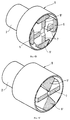
- фиг. 3 представляет собой схематический вид четырехполюсного электромагнитного ротора в соответствии с предлагаемым изобретением, где специально для понимания устройства этого ротора не показан его обтекатель;
- фиг. 4А, 4В, 4С представляет собой схематические виды в поперечном разрезе в трех различных положениях плоскости разреза ротора с четырьмя полюсами в соответствии с предлагаемым изобретением.Other features and advantages of the invention will be better understood from the following description of an example of its practical implementation, which gives links to the figures given in the appendix, among which:
- FIG. 1 is a schematic view of one magnetic part with two poles for a four-pole gear rotor in accordance with the invention;
- FIG. 2 is a schematic view of a part of a non-magnetic material forming a double jumper and constituting an integral part of a four-pole gear rotor in accordance with the invention;
- FIG. 3 is a schematic view of a four-pole electromagnetic rotor in accordance with the invention, where a fairing is not shown specifically for understanding the device of this rotor;
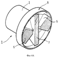
- FIG. 4A, 4B, 4C are schematic cross-sectional views in three different positions of the section plane of a four-pole rotor in accordance with the invention.
Ротор в соответствии с предлагаемым изобретением сконструирован таким образом, чтобы он был возможно более легким и имел простую и удобную конструкцию. The rotor in accordance with the invention is designed so that it is as light as possible and has a simple and convenient design.
Поиски возможностей облегчения конструкции привели к замене в максимально возможной степени используемых немагнитных материалов воздухом. Техническое решение, предложенное в данном изобретении, представляет собой полый ротор или ротор, содержащий выемки и имеющий магнитный зазор, возрастающий радиально по зонам, и гладкий геометрический аэродинамический зазор постоянной величины. The search for opportunities to facilitate the construction has led to the replacement of non-magnetic materials used to the extent possible with air. The technical solution proposed in this invention is a hollow rotor or a rotor containing recesses and having a magnetic gap that grows radially in the zones, and a smooth geometric aerodynamic gap of constant magnitude.
Стремление к получению простой и удобной в изготовлении конструкции обеспечило возможность сокращения количества различных конструктивных деталей ротора в соответствии с предлагаемым изобретением. The desire to obtain a simple and easy to manufacture design made it possible to reduce the number of various structural parts of the rotor in accordance with the invention.
Зубчатый электромагнитный ротор, имеющий 2N полюсов, в соответствии с предлагаемым изобретением содержит:
- первую деталь 1, изготовленную из магнитного материала и содержащую осевую втулку 2, имеющую свободный конец 3 и конец 4. снабженный N зубцами 5, проходящими в осевом направлении, локализованными по периферии, равномерно распределенными на ней, и определяющий обойму 8 между этими зубцами;
- вторую деталь, изготовленную из магнитного материала 1' с полярностью, противоположной полярности первой детали из магнитного материала 1, имеющую ту же форму, что и первая деталь из магнитного материала 1, располагающуюся против первой детали из магнитного материала 1, причем каждый зубец 5' этой второй детали из магнитного материала 1' располагается между двумя зубцами 5 первой детали из магнитного материала 1, и наоборот;
- немагнитные перемычки 7, вставленные между свободными концами 8, 8' зубцов 5, 5' каждой из деталей 1, 1' из магнитного материала и основанием обоймы 6, 6' противоположной детали 1', 1;
- немагнитные средства 9 закрытия ротора обтекателем.A gear electromagnetic rotor having 2N poles, in accordance with the invention contains:
- the
- the second part made of magnetic material 1 'with a polarity opposite to the polarity of the first part of
-
- non-magnetic means 9 closing the rotor of the fairing.
В варианте реализации предлагаемого изобретения, схематически представленном на приведенных в приложении фигурах, число N равно 2. Таким образом, конец 4 (или соответственно 4') втулки 2 (или соответственно 2') содержит два диаметрально противоположных зубца 5 (или соответственно 5'). In the embodiment of the invention, shown schematically in the figures given in the appendix, the number N is 2. Thus, the end 4 (or 4 ') of the sleeve 2 (or 2', respectively) contains two diametrically opposite teeth 5 (or 5 ', respectively) .
Зубцы 5, 5' имеют продольную наружную поверхность 10 с выполненными на ней зонами постепенно меняющегося магнитного зазора. The
В представленном здесь в качестве примера варианте реализации предлагаемого изобретения продольная наружная поверхность 10 содержит одну центральную зону 11, радиус которой равен наружному радиусу ротора под обтекателем 9, и две боковые скошенные зоны 12a, 12b, располагающиеся по одну и по другую стороны от упомянутой центральной зоны 11. Эти скошенные формы образуют постепенно возрастающие радиальные магнитные зазоры. In the exemplary embodiment of the invention presented here, the longitudinal outer surface 10 comprises one central zone 11, the radius of which is equal to the outer radius of the rotor under the
В целом форма наружной продольной поверхности 10 позволяет оптимизировать прохождение магнитного потока между центральной зоной 11 и статором данной вращающейся синхронной электрической машины. In General, the shape of the outer longitudinal surface 10 allows you to optimize the passage of magnetic flux between the Central zone 11 and the stator of this rotating synchronous electric machine.
Зубцы ротора в соответствии с предлагаемым изобретением имеют внутренние скошенные поверхности 13, точка схождения которых 14 располагается в непосредственной близости от центра упомянутой обоймы 6. The teeth of the rotor in accordance with the invention have internal beveled surfaces 13, the convergence point of which 14 is located in the immediate vicinity of the center of the cage 6.
Эта характеристика имеет целью сформировать значительное по величине немагнитное пространство между двумя магнитными массами, примыкающими друг к другу и имеющими противоположные полярности (примыкающие друг к другу зубцы). Это немагнитное пространство позволяет ограничить рассеяние магнитного потока, проходящего непосредственно между двумя соседними полюсами противоположной полярности вместо того, чтобы проходить через статор. This characteristic aims to form a significant non-magnetic space between two magnetic masses adjacent to each other and having opposite polarities (teeth adjacent to each other). This non-magnetic space allows you to limit the scattering of the magnetic flux passing directly between two adjacent poles of opposite polarity instead of passing through the stator.
В представленном здесь варианте реализации предлагаемого изобретения зубцы ротора устроены так, что они имеют достаточно большое основание в контакте с осевой втулкой для того, чтобы воспринимать механические изгибающие напряжения зубцов, возникающие под действием центробежных сил, и заостренный свободный конец для того, чтобы ограничить массу на конце зубца и уменьшить таким образом упомянутые изгибающие напряжения в его основании. In the embodiment of the invention presented here, the rotor teeth are arranged so that they have a sufficiently large base in contact with the axial sleeve in order to perceive the mechanical bending stresses of the teeth arising under the action of centrifugal forces, and a pointed free end in order to limit the mass to the end of the tooth and thus reduce the mentioned bending stresses at its base.
Немагнитные перемычки 7, вставленные между свободными концами 8, 8' зубцов 5, 5' каждой из деталей 1, 1' из магнитного материала и основанием обоймы 6', 6 противоположной магнитной детали 1', 1, предназначены для того, чтобы создать некоторое немагнитное пространство между поляризованными зубцами одной из магнитных деталей и основанием обоймы другой магнитной детали противоположной полярности, достаточное для того, чтобы минимизировать рассеяние магнитного потока между зубцами и противоположной магнитной деталью.
Эти немагнитные перемычки 7 выполняют также определенную механическую роль, имея целью обеспечить осевое и радиальное сцепление данного ротора. Это достигается тем, что упомянутые немагнитные перемычки обеспечивают жесткую механическую связь между концами зубцов одной магнитной детали и основанием обоймы другой магнитной детали. These
В представленном на приведенных в приложении фигурах варианте реализации предлагаемого изобретения используются двойные немагнитные перемычки, которые в дополнение к жестко механической связи между концами зубцов одной магнитной детали и основанием обоймы другой магнитной детали обеспечивают непосредственную жесткую связь между диаметрально противоположными зубцами, что в значительной мере способствует надежному сцеплению ротора в радиальном направлении. In the embodiment of the invention presented in the figures given in the appendix, double non-magnetic jumpers are used, which in addition to the rigidly mechanical connection between the ends of the teeth of one magnetic part and the base of the holder of the other magnetic part provide direct rigid connection between diametrically opposite teeth, which greatly contributes to reliable rotor clutch in the radial direction.
На фиг. 2 схематически представлена моноблочная двойная немагнитная перемычка в соответствии с предлагаемым изобретением. In FIG. 2 schematically shows a monoblock double non-magnetic jumper in accordance with the invention.
Эта моноблочная двойная перемычка имеет в качестве своей дополнительной характеристики статически и динамически уравновешенную форму по отношению к оси вращения данного ротора. This monoblock double jumper has as its additional characteristic a statically and dynamically balanced shape with respect to the axis of rotation of this rotor.
Таким образом, при вращении ротора в этой двойной моноблочной перемычке обеспечивается полное уравновешивание возникающих центробежных сил. То обстоятельство, что данная двойная перемычка выполнена моноблочной, дополнительно повышает надежность конструкции. Thus, when the rotor rotates in this double monoblock jumper, full balancing of the resulting centrifugal forces is ensured. The fact that this double jumper is made monoblock additionally increases the reliability of the design.
В другом возможном варианте реализации предлагаемого изобретения, не представленном здесь, единственная моноблочная деталь обеспечивает функции перемычек для всей совокупности зубцов электромагнитного ротора. In another possible embodiment of the invention, not presented here, a single monoblock part provides jumper functions for the entire set of teeth of the electromagnetic rotor.
Упомянутые перемычки, одиночные или многосторонние, спроектированы таким образом, чтобы обеспечить выполнение своих немагнитных и механических функций, которые от них требуются, при минимуме используемого материала. The mentioned jumpers, single or multilateral, are designed in such a way as to ensure the performance of their non-magnetic and mechanical functions, which are required of them, with a minimum of material used.
Соединение немагнитных перемычек с зубцами ротора и/или с основаниями обойм может быть осуществлено при помощи любых известных и подходящих в данном случае средств, например, при помощи сварки, пайки, винтового соединения или приклеивания. В соответствии с предлагаемым изобретением механические характеристики средств соединения, требуемые для реализации соединений в данном случае, должны отвечать значительно жестким условиям, чем для сплошных роторов. The connection of non-magnetic jumpers with the teeth of the rotor and / or with the base of the cages can be carried out using any known and suitable means in this case, for example, by welding, soldering, screw connection or gluing. In accordance with the invention, the mechanical characteristics of the means of connection required for the implementation of the compounds in this case must meet significantly more stringent conditions than for solid rotors.
Для того, чтобы сохранить для конструкции ротора оптимальный аэродинамический профиль, зубцы ротора в соответствии с предлагаемым изобретением закрываются специальным аэродинамическим обтекателем с помощью немагнитных средств капотирования. In order to maintain the optimal aerodynamic profile for the rotor design, the teeth of the rotor in accordance with the invention are closed with a special aerodynamic fairing using non-magnetic means of bonding.
Вследствие специальной конструкции ротора в данном случае этот аэродинамический обтекатель может не образовывать конструктивный элемент осевого или радиального сцепления элементов ротора и, следовательно, может быть изготовлен из любого подходящего в данном случае немагнитного материала, причем толщина этого материала может выбираться такой, чтобы обеспечить прочность этого обтекателя только по отношению к своей собственной инерции. Due to the special design of the rotor in this case, this aerodynamic fairing may not form a structural element of axial or radial engagement of the rotor elements and, therefore, can be made of any suitable non-magnetic material in this case, and the thickness of this material can be chosen so as to ensure the strength of this fairing only in relation to its own inertia.
В способе реализации предлагаемого изобретения, представленном здесь, средства капотирования, образующие аэродинамический обтекатель, содержат полый цилиндр, закрывающий зубцы ротора, и два торцевых кольцевых фланца, охватывающих втулки и закрывающих основания упомянутого цилиндра. In the method of implementing the present invention presented here, the means of bonding forming an aerodynamic fairing comprise a hollow cylinder covering the teeth of the rotor and two end ring flanges covering the bushings and covering the bases of the said cylinder.
Разумеется, предлагаемое изобретение не ограничивается описанным здесь и представленным на приведенных в приложении фигурах способом реализации. Это изобретение может иметь многочисленные варианты, не выходящие за его рамки и доступные специалисту в данной области техники. В частности, не выходя за рамки предлагаемого изобретения, можно увеличить число полюсов ротора. Of course, the present invention is not limited to the method of implementation described in the figures presented in the appendix. This invention may have numerous variations that are not beyond its scope and available to a person skilled in the art. In particular, without going beyond the scope of the present invention, it is possible to increase the number of poles of the rotor.
Claims (6)
Applications Claiming Priority (2)
| Application Number | Priority Date | Filing Date | Title |
|---|---|---|---|
| FR9600211A FR2743455B1 (en) | 1996-01-10 | 1996-01-10 | MAGNETOELECTRIC ROTOR WITH CLAWS |
| FR9600211 | 1996-01-10 |
Publications (2)
| Publication Number | Publication Date |
|---|---|
| RU97100981A RU97100981A (en) | 1999-02-10 |
| RU2145459C1 true RU2145459C1 (en) | 2000-02-10 |
Family
ID=9488008
Family Applications (1)
| Application Number | Title | Priority Date | Filing Date |
|---|---|---|---|
| RU97100981A RU2145459C1 (en) | 1996-01-10 | 1997-01-09 | Toothed electromagnetic rotor |
Country Status (20)
| Country | Link |
|---|---|
| US (1) | US5786652A (en) |
| EP (1) | EP0784368B1 (en) |
| JP (1) | JP3818714B2 (en) |
| KR (1) | KR100256188B1 (en) |
| CN (1) | CN1080945C (en) |
| AT (1) | ATE205024T1 (en) |
| BR (1) | BR9700035A (en) |
| CA (1) | CA2194792A1 (en) |
| CZ (1) | CZ287892B6 (en) |
| DE (1) | DE69706330T2 (en) |
| DK (1) | DK0784368T3 (en) |
| ES (1) | ES2159818T3 (en) |
| FR (1) | FR2743455B1 (en) |
| HU (1) | HU220413B (en) |
| PL (1) | PL182491B1 (en) |
| PT (1) | PT784368E (en) |
| RO (1) | RO116989B1 (en) |
| RU (1) | RU2145459C1 (en) |
| UA (1) | UA44276C2 (en) |
| ZA (1) | ZA97181B (en) |
Cited By (1)
| Publication number | Priority date | Publication date | Assignee | Title |
|---|---|---|---|---|
| RU2551125C2 (en) * | 2013-01-28 | 2015-05-20 | Павел Анатольевич Назаров | Method of compensation of centrifugal force of electrical machine rotor, and anti-centrifugal generator and anti-centrifugal electric motor for its implementation and their high-frequency power supply network |
Families Citing this family (12)
| Publication number | Priority date | Publication date | Assignee | Title |
|---|---|---|---|---|
| FR2744854B1 (en) * | 1996-02-08 | 1998-03-13 | Gec Alsthom Moteurs Sa | METHOD FOR MANUFACTURING A MAGNETOELECTRIC ROTOR WITH ROTORS, ROTOR MANUFACTURED BY SUCH A METHOD |
| US6777844B2 (en) * | 2000-10-24 | 2004-08-17 | Rexair, Inc. | Brushless motor |
| US20030214194A1 (en) * | 2002-05-20 | 2003-11-20 | General Electric Company | Rotor assembly and method of making |
| DE102010019502B4 (en) * | 2010-05-06 | 2023-03-23 | Bühler Motor GmbH | Pump with integrated electronically commutated DC motor |
| US9246364B2 (en) | 2012-10-15 | 2016-01-26 | Regal Beloit America, Inc. | Radially embedded permanent magnet rotor and methods thereof |
| US9831727B2 (en) | 2012-10-15 | 2017-11-28 | Regal Beloit America, Inc. | Permanent magnet rotor and methods thereof |
| US9882440B2 (en) | 2012-10-15 | 2018-01-30 | Regal Beloit America, Inc. | Radially embedded permanent magnet rotor and methods thereof |
| US9099905B2 (en) | 2012-10-15 | 2015-08-04 | Regal Beloit America, Inc. | Radially embedded permanent magnet rotor and methods thereof |
| US9362792B2 (en) | 2012-10-15 | 2016-06-07 | Regal Beloit America, Inc. | Radially embedded permanent magnet rotor having magnet retention features and methods thereof |
| FR3037198B1 (en) * | 2015-06-08 | 2018-10-12 | Valeo Equipements Electriques Moteur | ROTOR FOR ROTATING ELECTRIC MACHINE |
| FR3040561B1 (en) * | 2015-09-01 | 2017-08-25 | Valeo Equip Electr Moteur | ROTATING ELECTRICAL MACHINE WITH ROTOR COMPRISING CLAY-SHAPED POLES |
| JP6647463B1 (en) * | 2018-07-17 | 2020-02-14 | 三菱電機株式会社 | Rotating electric machine |
Family Cites Families (11)
| Publication number | Priority date | Publication date | Assignee | Title |
|---|---|---|---|---|
| US3223866A (en) * | 1960-09-13 | 1965-12-14 | Trw Inc | Alternator |
| US3230404A (en) * | 1961-10-10 | 1966-01-18 | Chrysler Corp | Damping means for claw tooth rotors |
| US3215878A (en) * | 1961-12-26 | 1965-11-02 | Emerson Electric Co | Brushless alternator |
| DE1488702B2 (en) * | 1965-08-19 | 1970-09-10 | Siemens AG, 1000 Berlin u. 8000 München | Synchronous machine with excitation windings excited in opposite directions and a winding-free rotor |
| US3493800A (en) * | 1968-06-12 | 1970-02-03 | Edward L Barrett | Brushless alternator |
| FR2087516A5 (en) * | 1970-05-21 | 1971-12-31 | Volchkov Viktor | |
| FR2676873B1 (en) * | 1991-05-21 | 1993-08-06 | Valeo Equipements Electr Mo | THREE - PHASE ALTERNATOR FOR MOTOR VEHICLES. |
| JP3446313B2 (en) * | 1993-08-30 | 2003-09-16 | 株式会社デンソー | Rotating electric machine rotor |
| JP3239630B2 (en) * | 1993-11-29 | 2001-12-17 | 株式会社デンソー | AC generator for vehicles |
| US5539265A (en) * | 1994-10-11 | 1996-07-23 | Ford Motor Company | Self-aligning rotor assembly |
| US5519277A (en) * | 1994-12-27 | 1996-05-21 | Ford Motor Company | Rotor assembly for an electric machine |
-
1996
- 1996-01-10 FR FR9600211A patent/FR2743455B1/en not_active Expired - Fee Related
-
1997
- 1997-01-02 ES ES97400006T patent/ES2159818T3/en not_active Expired - Lifetime
- 1997-01-02 DK DK97400006T patent/DK0784368T3/en active
- 1997-01-02 EP EP97400006A patent/EP0784368B1/en not_active Expired - Lifetime
- 1997-01-02 DE DE69706330T patent/DE69706330T2/en not_active Expired - Fee Related
- 1997-01-02 AT AT97400006T patent/ATE205024T1/en not_active IP Right Cessation
- 1997-01-02 PT PT97400006T patent/PT784368E/en unknown
- 1997-01-03 UA UA97010001A patent/UA44276C2/en unknown
- 1997-01-08 HU HU9700047A patent/HU220413B/en not_active IP Right Cessation
- 1997-01-08 RO RO97-00021A patent/RO116989B1/en unknown
- 1997-01-09 CA CA002194792A patent/CA2194792A1/en not_active Abandoned
- 1997-01-09 US US08/781,589 patent/US5786652A/en not_active Expired - Fee Related
- 1997-01-09 BR BR9700035A patent/BR9700035A/en active Search and Examination
- 1997-01-09 CN CN97101831A patent/CN1080945C/en not_active Expired - Fee Related
- 1997-01-09 ZA ZA97181A patent/ZA97181B/en unknown
- 1997-01-09 RU RU97100981A patent/RU2145459C1/en not_active IP Right Cessation
- 1997-01-09 KR KR1019970000347A patent/KR100256188B1/en not_active IP Right Cessation
- 1997-01-09 PL PL97317863A patent/PL182491B1/en not_active IP Right Cessation
- 1997-01-10 CZ CZ199789A patent/CZ287892B6/en not_active IP Right Cessation
- 1997-01-10 JP JP00305897A patent/JP3818714B2/en not_active Expired - Fee Related
Non-Patent Citations (1)
| Title |
|---|
| Апсит В.В. Бесконтактные электрические машины. Вып. 16. - Рига: Зинатне, 1977, с.9-10, рис.5 а, б. * |
Cited By (1)
| Publication number | Priority date | Publication date | Assignee | Title |
|---|---|---|---|---|
| RU2551125C2 (en) * | 2013-01-28 | 2015-05-20 | Павел Анатольевич Назаров | Method of compensation of centrifugal force of electrical machine rotor, and anti-centrifugal generator and anti-centrifugal electric motor for its implementation and their high-frequency power supply network |
Also Published As
| Publication number | Publication date |
|---|---|
| HUP9700047A2 (en) | 1997-09-29 |
| JPH09215232A (en) | 1997-08-15 |
| CN1080945C (en) | 2002-03-13 |
| UA44276C2 (en) | 2002-02-15 |
| CZ8997A3 (en) | 1997-07-16 |
| DE69706330D1 (en) | 2001-10-04 |
| ZA97181B (en) | 1997-07-23 |
| BR9700035A (en) | 1998-11-10 |
| PL182491B1 (en) | 2002-01-31 |
| HU220413B (en) | 2002-01-28 |
| JP3818714B2 (en) | 2006-09-06 |
| KR100256188B1 (en) | 2000-05-15 |
| CN1159088A (en) | 1997-09-10 |
| HUP9700047A3 (en) | 2000-08-28 |
| KR970060633A (en) | 1997-08-12 |
| PT784368E (en) | 2001-12-28 |
| DE69706330T2 (en) | 2002-05-08 |
| ES2159818T3 (en) | 2001-10-16 |
| FR2743455B1 (en) | 1998-02-06 |
| PL317863A1 (en) | 1997-07-21 |
| EP0784368B1 (en) | 2001-08-29 |
| CA2194792A1 (en) | 1997-07-11 |
| HU9700047D0 (en) | 1997-02-28 |
| RO116989B1 (en) | 2001-08-30 |
| ATE205024T1 (en) | 2001-09-15 |
| FR2743455A1 (en) | 1997-07-11 |
| US5786652A (en) | 1998-07-28 |
| CZ287892B6 (en) | 2001-03-14 |
| EP0784368A1 (en) | 1997-07-16 |
| DK0784368T3 (en) | 2001-12-10 |
Similar Documents
| Publication | Publication Date | Title |
|---|---|---|
| RU2145459C1 (en) | Toothed electromagnetic rotor | |
| US4661736A (en) | Rotor for a synchronous motor | |
| EP0726638B1 (en) | Electromagnetic rotary machine comprising an electromagnetic bearing | |
| RU2364017C2 (en) | Electric motor | |
| JPH09508520A (en) | Motor including permanent magnet rotor | |
| GB2404501A (en) | Rotor structure of a line-start permanent magnet (LSPM) synchronous motor | |
| US5512792A (en) | Electric motor with high power and high rotational speed | |
| CA1184964A (en) | Rotor for stepper motor | |
| JP3207418U (en) | Single phase motor | |
| EP0187038A3 (en) | Torque motor with high torque poles and magnetic centering spring adjustment | |
| CN107612165B (en) | Conical air gap axial double-loop magnetic field permanent magnet synchronous motor | |
| JPH10225032A (en) | Rotor for permanent magnet type dynamo-electric machine and its manufacture | |
| CN112491244B (en) | Magnetic adjusting ring supporting structure, magnetic adjusting ring component, magnetic gear and composite motor | |
| KR920000500B1 (en) | Rotor structure of synchronous motor | |
| JPS62141955A (en) | 2-phase step motor | |
| EP3683932B1 (en) | Motor rotor | |
| GB2246401A (en) | Magnetic thrust bearing | |
| SU873343A1 (en) | High speed electric machine rotor | |
| RU2283527C2 (en) | Low-speed induction motor | |
| SU1045332A1 (en) | Rotor of synchronous machine with permanent magnets | |
| SU1108565A1 (en) | Rotor for synchronous electric machine | |
| JPH0213771Y2 (en) | ||
| SU1515277A1 (en) | Electric motor | |
| GB2225173A (en) | Stator windings for homopolar electrical machines | |
| JP2023085240A (en) | Rotor module for rotor of rotary electric machine |
Legal Events
| Date | Code | Title | Description |
|---|---|---|---|
| MM4A | The patent is invalid due to non-payment of fees |
Effective date: 20070110 |