RU2115246C1 - Method of transmission of data packs in general- purpose communication channel and control device - Google Patents
Method of transmission of data packs in general- purpose communication channel and control device Download PDFInfo
- Publication number
- RU2115246C1 RU2115246C1 RU97105517A RU97105517A RU2115246C1 RU 2115246 C1 RU2115246 C1 RU 2115246C1 RU 97105517 A RU97105517 A RU 97105517A RU 97105517 A RU97105517 A RU 97105517A RU 2115246 C1 RU2115246 C1 RU 2115246C1
- Authority
- RU
- Russia
- Prior art keywords
- input
- output
- transmission
- signal
- communication channel
- Prior art date
Links
Images


Abstract
Description
Предлагаемые объекты изобретения объединены единым изобретательским замыслом, относятся к области связи, а именно к технике передачи данных, и могут быть использованы в сетях радиосвязи с пакетной коммутацией. The proposed objects of the invention are united by a single inventive concept, relate to the field of communication, namely to the technology of data transfer, and can be used in radio communication networks with packet switching.
Известно, что в радиосетях передачи данных с целью улучшения эффективности использования общего частотно-временного ресурса канала связи применяют различные методы, в частности метод, основанный на коммутации пакетов [1, с.6-10]. Реализация этого метода позволяет всем установкам пакетной радиосвязи (УПР), работающим в сети, коллективно использовать выделенную общую для всех рабочую частоту приема-передачи канала связи (такие каналы связи называются каналами связи общего пользования (КОП). В этом случае УПР сети осуществляют попытки передачи пакетов любые моменты времени независимо друг от друга. Однако при одновременной передаче пакетов данных (ПД) несколькими УПР в КОП происходят наложения во времени пакетов данных, приводящие к их столкновениям. Такие ситуации называются конфликтными. Возникающие столкновения искажают передаваемую информацию и не позволяют принять ПД. Для уменьшения числа столкновений и уменьшения вероятности конфликтных ситуаций в КОП используют различные способы управления передачей пакетов данных. В общем случае управление передачей ПД заключается в определении однозначных и обязательных для выполнения всеми УПР сети действий по передачи пакетов данных в канал связи общего пользования. It is known that in radio data networks in order to improve the efficiency of using the total time-frequency resource of a communication channel, various methods are used, in particular, a method based on packet switching [1, p.6-10]. The implementation of this method allows all packet radio communication installations (UPR) operating in the network to collectively use the all-in-one shared frequency of transmission and reception of a communication channel (such communication channels are called public communication channels (CPC). In this case, the UPR networks attempt transmission packets at any time points independently of each other.However, during simultaneous transmission of data packets (PDs) by several controllers in the CPC, superimposed data packets occur in time, leading to their collisions. Conflict arises which distort the transmitted information and do not allow receiving PDs. To reduce the number of collisions and reduce the likelihood of conflict situations, CPCs use various methods for controlling the transmission of data packets. actions to transfer data packets to the public communication channel.
Известен способ гибкого управления передачей пакетов данных в КОП [2, с. 54]. Данный способ предусматривает следующий порядок действий. A known method of flexible control of the transmission of data packets in the CPC [2, p. 54]. This method provides the following procedure.
С поступлением на j-ю УПР пакета данных, где j ∈ {1,2,...N}, а N-общее число УПР, работающих в пакетной радиосети (ПРС), последняя осуществляет прием (или контроль) на рабочей частоте приема-передачи сигнала несущего колебания k-й УПР (где k ≠ j, k ∈ {1,2,...N}), который понимается как сигнал занятости КОП. Если сигнал занятости не обнаружен, то j-я УПР передает ПД через случайный промежуток времени ![]()
![]()
Временные диаграммы состояния КОП для способа с гибким управлением передачей ПД представлены в [2, с. 54]. Timing diagrams of the state of the CPC for a method with flexible control of PD transmission are presented in [2, p. 54].
Известен также способ с жестким управлением передачей пакетов данных в КОП, описанный [2, с.55]. Его отличие от предыдущего заключается в том, что начало передачи ПД в КОП происходит не через случайный промежуток времени с момента окончания сигнала занятости (сигнала несущего колебания) на рабочей частоте приема-передачи, а немедленно. При этом способе так же, как и при предыдущем, после окончания передачи ПД УПР ожидает подтверждение (квитанцию) их приема в специально выделенном интервале времени Δτож сразу же после окончания передачи ПД. В [2, с.55] представлены временные диаграммы состояния КОП для способа с жестким управлением передачей ПД.There is also a method with tight control of the transmission of data packets in the CPC, described [2, p. 55]. Its difference from the previous one is that the beginning of the transmission of the AP to the CPC does not occur after a random period of time from the end of the busy signal (carrier oscillation signal) at the working transmit-receive frequency, but immediately. With this method, as well as with the previous one, after the end of the transmission, the ATR awaits confirmation (receipt) of their receipt in a specially selected time interval Δτ wait immediately after the end of the transmission of the AP. In [2, p. 55], time diagrams of the state of the CPC are presented for a method with tight control of PD transmission.
Однако указанные аналоги имеют недостатки. Например, обладают низкой пропускной способностью, что объясняется большим количеством конфликтных ситуаций в канале связи общего пользования при высоком входном информационном потоке ПД в сеть пакетной радиосвязи. Процедура управления передачей пакетов данных в КОП не позволяет успешно осуществлять передачу ПД с учетом категорий срочности. However, these analogues have disadvantages. For example, they have low bandwidth, which is explained by a large number of conflicts in the public communication channel with a high input information flow of PD into the packet radio communication network. The procedure for controlling the transfer of data packets to the CPC does not allow the successful transfer of PD taking into account the categories of urgency.
Наиболее близким по своей технической сущности по отношению к заявляемому способу является способ P-жесткого управления передачей ПД и КОП, описанный в [2, с.57]. Данный способ относится к числу синхронных и предусматривает потактную работу ПРС с частотой 1/T, где T-длительность такта работы сети. По способу-прототипу j-я УПР, на вход которой поступил ПД, вначале осуществляет контроль занятости КОП на наличие сигнала несущей частоты. При отсутствии занятости j-я УПР с вероятностью P начинает передавать ПД, или с вероятностью (1-P) повторяет процедуру, описанную выше в следующем такте ее работы, начиная с момента контроля КОП. Прием квитанции (или подтверждения) аналогичен процедуре, приведенной для способа с гибким и жестким управлением передачей ПД в КОП. The closest in its technical essence in relation to the claimed method is a method of P-hard control of the transmission of PD and CPC, described in [2, p. 57]. This method belongs to the number of synchronous ones and provides for the tactless operation of the ORS with a frequency of 1 / T, where T is the duration of the network operation cycle. According to the prototype method, the jth UPR, at the input of which the PD arrived, first monitors the employment of the CPC for the presence of a carrier frequency signal. In the absence of employment, the j-th ASR with probability P begins to transmit the AP, or with probability (1-P) repeats the procedure described above in the next step of its operation, starting from the moment of control of the CPC. The receipt of the receipt (or confirmation) is similar to the procedure described for the method with flexible and rigid control of the transfer of PD to the CPC.
Однако способ с P-жестким управлением передачей пакетов данных в КОП так же, как и другие, обладает не достаточной пропускной способностью в условиях высокой информационной нагрузки. Кроме того, способ-прототип не учитывает категории срочности ПД, поступающих на УПР на передачу в КОП. Вследствие этого ПД с различными категориями срочности имеют равные вероятности как быть переданными, так и попасть в конфликтные ситуации в КОП. Такие конфликты приведут к неравнозначным задержкам передачи ПД с различными приоритетами. Например, высокоприоритетный ПД и низкоприоритетный ПД будут обладать одинаковыми вероятностями быть переданными в КОП, тогда как, согласно требованиям, предъявляемым к первым, предусматривается их доведение до соответствующей УПР немедленно, а вторым - в последнюю очередь. However, the method with P-tight control of the transmission of data packets to the CPC, like the others, does not have sufficient bandwidth under high information load conditions. In addition, the prototype method does not take into account the categories of urgency of PDs received by the RMA for transmission to the CPC. As a result of this, PDs with various categories of urgency have equal probabilities of both being transferred and getting into conflict situations in the CPC. Such conflicts will lead to unequal delays in transmitting PDs with different priorities. For example, a high-priority PD and a low-priority PD will have the same probability of being transferred to the CPC, whereas, according to the requirements for the former, it is envisaged to bring them to the appropriate SPS immediately, and the latter in the last turn.
Известны устройства для управления передачей пакетов данных по радиоканалу. Known devices for controlling the transmission of data packets over the air.
Устройство для управления передачей пакетов данных по радиоканалу [3] содержит последовательно соединенные первый триггер и первый элемент запрета, а также элемент задержки, элемент И и элемент ИЛИ, последовательно соединенные первый и второй формирователи импульсов, второй элемент запрета и второй триггер, а также третий формирователь импульсов и третий триггер. Выход синхронизатора подключен к второму входу первого элемента запрета, выход которого подключен к первому входу элемента ИЛИ. К второму входу элемента ИЛИ подключен выход второго триггера. Первый вход первого триггера объединен с первым входом элемента И, вторым входом второго элемента запрета и входом третьего формирователя импульсов. Выход последнего через элемент задержки подключен к второму входу первого триггера. Выход второго формирователя импульсов подключен к второму входу элемента И, выход которого подключен к первому входу третьего триггера. Второй вход третьего триггера объединен с вторым входом второго триггера и третьим входом первого элемента запрета. A device for controlling the transmission of data packets over a radio channel [3] comprises a first trigger and a first inhibit element, as well as a delay element, an AND element and an OR element, a first and second pulse shaper, a second inhibit element and a second trigger, and a third one pulse shaper and the third trigger. The synchronizer output is connected to the second input of the first prohibition element, the output of which is connected to the first input of the OR element. The output of the second trigger is connected to the second input of the OR element. The first input of the first trigger is combined with the first input of the AND element, the second input of the second inhibit element and the input of the third pulse shaper. The output of the latter through the delay element is connected to the second input of the first trigger. The output of the second pulse shaper is connected to the second input of the And element, the output of which is connected to the first input of the third trigger. The second input of the third trigger is combined with the second input of the second trigger and the third input of the first inhibit element.
Однако известное устройство имеет недостатки. Оно обладает низкой пропускной способностью и не позволяет при высокой информационной нагрузке в КОП уменьшить вероятность возникновения конфликтных ситуаций (перекрытия пакетов данных во времени) между УПР при передаче ПД с различной категорией срочности. Кроме того, после неудачной попытки передать ПД в устройство необходимо повторно подать команду ЗАПРОС ПЕРЕДАЧИ с целью доведения ПД до соответствующей УПР. However, the known device has disadvantages. It has a low bandwidth and does not allow for a high information load in the CPC to reduce the likelihood of conflict (overlapping data packets in time) between the controllers when transmitting APs with a different urgency category. In addition, after an unsuccessful attempt to transfer the PD to the device, it is necessary to re-send the TRANSFER REQUEST command in order to bring the PD to the corresponding control.
Наиболее близким по своей технической сущности является устройство [4]. The closest in its technical essence is the device [4].
Устройство-прототип состоит из последовательно соединенных синхронизатора, первого элемента И, элемента задержки, элемента ИЛИ, счетчика, триггера цикла передачи, генератора случайных чисел, блока сравнения, триггера разрешения передачи, второго элемента И и формирователя импульсов. Вход последнего подключен к первому входу элемента ИЛИ, к входу которого, а также к входу элемента задержки подключен выход триггера разрешения передачи. Второй вход триггера разрешения передачи соединен с первым входом элемента И. К второму и третьему входам второго элемента И подключены соответственно выход синхронизатора и выход триггера цикла передачи. Второй вход последнего объединен с вторым входом первого элемента И, к третьему и четвертому входам которого подключены соответственно выход триггера цикла передачи и выход элемента задержки. Выход первого элемента И подключен к входу счетчика, второй выход которого подключен к второму входу блока сравнения, а выход второго элемента И подключен к входу генератора случайных чисел. The prototype device consists of a series-connected synchronizer, a first AND element, a delay element, an OR element, a counter, a transmission cycle trigger, a random number generator, a comparison unit, a transmission enable trigger, a second And element, and a pulse shaper. The input of the latter is connected to the first input of the OR element, to the input of which, as well as to the input of the delay element, the output of the transfer enable trigger is connected. The second input of the trigger enable transmission is connected to the first input of the element I. To the second and third inputs of the second element And are connected respectively the output of the synchronizer and the output of the trigger of the transmission cycle. The second input of the latter is combined with the second input of the first AND element, to the third and fourth inputs of which the output of the trigger of the transmission cycle and the output of the delay element are connected, respectively. The output of the first element And is connected to the input of the counter, the second output of which is connected to the second input of the comparison unit, and the output of the second element And is connected to the input of the random number generator.
Однако устройство-прототип имеет недостатки. Во-первых, устройство имеет низкую пропускную способность канала связи общего пользования при передаче ПД с различными приоритетами в наихудших условиях передачи (высокий входной информационный поток). Это обусловлено большой вероятностью возникновения конфликтных ситуаций, в условиях когда все УПР сети одновременно осуществляют попытки передавать пакеты данных в канал связи общего пользователя. Во-вторых, оно не позволяет управлять передачей пакетов данных с учетом категорий срочности последних. However, the prototype device has disadvantages. Firstly, the device has a low bandwidth of the public communication channel when transmitting PDs with various priorities in the worst transmission conditions (high input information stream). This is due to the high likelihood of conflict situations in the conditions when all the control networks of the network simultaneously attempt to transmit data packets to the communication channel of a common user. Secondly, it does not allow controlling the transmission of data packets taking into account the categories of urgency of the latter.
Целью заявляемых объектов изобретения является разработка способа и устройства управления передачей пакетов данных в канале связи общего пользования, которые обеспечивают более высокую пропускную способность канала связи общего пользования при передаче пакетов данных с различной категорией срочности в условиях высокой информационной нагрузки. The aim of the claimed objects of the invention is to develop a method and device for controlling the transmission of data packets in a public communication channel, which provide higher bandwidth of the public communication channel when transmitting data packets with various categories of urgency in conditions of high information load.
Поставленная цель достигается тем, что при известном способе, заключающемся в приеме сигнала занятости канала связи общего пользования каждой из N установок пакетной радиосвязи (N ≥ 3), формировании с заданной вероятностью сигнала разрешения передачи пакетов данных, синхронном формировании сигналов команды управления, передаче пакетов данных при поступлении сигнала разрешения передачи и одновременном отсутствии сигнала занятости канала связи общего пользования, повторном синхронном формировании сигнала команды управления при отсутствии сигнала разрешения передачи или наличии сигнала занятости канала связи общего пользования в текущем такте и передаче в последующем такте работы канала связи, предварительно формируют импульсы приоритета пакета данных длительностью ΔTj1, , где l ∈ {1,2,...,L}, l - номер приоритета пакета данных, L - номер приоритета пакета данных, а j - номер УПР, причем Tj1 >..>ΔTjl>..>ΔTjL и 0<ΔTjl<T, где T - длительность такта работы канала связи, одновременно генерируют случайный импульс длительностью Δtc , с равновероятным законом его распределения на временном интервале ]O, T[ и при выполнении условия Δtc∈JO, T[ генерируют сигнал разрешения, в противном случае действия по формированию сигнала разрешения повторяют в следующем такте работы канала связи. Длительность импульса Δt выбирают в пределах Δt =(0,05...0,1) (T/L). При приеме пакета данных с l-м приоритетом дополнительно на соответствующей установке пакетной радиосвязи формируют сигнал подтверждения его приема, передают сигнал подтверждения, а при отсутствии сигнала подтверждения действия по управлению, передачей пакета данных с l-м приоритетом повторяют.This goal is achieved by the fact that with the known method, which consists in receiving a busy signal of a public communication channel of each of N packet radio communication installations (N ≥ 3), generating with a given probability a permission signal for transmitting data packets, synchronously generating control command signals, transmitting data packets upon receipt of a transmission authorization signal and the simultaneous absence of a busy signal of a public communication channel, repeated synchronous generation of a control command signal when there is no If the transmission enable signal or the presence of the busy signal of the public communication channel in the current cycle and transmission in the subsequent cycle of the communication channel operation, precedence pulses of a data packet of duration ΔT j1 ,, where l ∈ {1,2, ..., L}, l is the priority number of the data packet, L is the priority number of the data packet, and j is the control number, and T j1 >..> ΔT jl >..> ΔT jL and 0 <ΔT jl <T, where T is the duration of the channel communication, at the same time generate a random pulse of Δt c, with uniform distribution of its law on time inte shaft] O, T [and, when the condition Δt c ∈JO, T [generating a permission signal, otherwise steps to permit the formation of the signal is repeated in the next cycle of operation of the communication channel. The pulse duration Δt is selected in the range Δt = (0.05 ... 0.1) (T / L). When receiving a data packet with the l-th priority, in addition to the corresponding packet radio installation, a confirmation signal is received, a confirmation signal is transmitted, and if there is no confirmation signal, the control actions by transmitting the data packet with the l-th priority are repeated.
Указанная выше совокупность существенных признаков позволяет увеличить пропускную способность КОП при передаче пакетов данных с различными приоритетами путем формирования требуемых упорядоченных значений вероятностей передачи при управлении передачи ПД в КОП в условиях высокой информационной нагрузки. The above set of essential features allows you to increase the throughput of the CPC when transmitting data packets with different priorities by forming the required ordered values of the transmission probabilities when controlling the transmission of AP to CPC under high information load conditions.
Поставленная цель в заявляемом устройстве достигается тем, что в известное устройство управления передачей пакетов данных в канал связи общего пользования, содержащее счетчик, формирователь длинных импульсов, триггер, синхронизатор, элемент ИЛИ, генератор сигналов разрешения передачи, дополнительно введены блок считывания, дешифратор, первый и второй элементы ЗАПРЕТ, D-триггер и L-входовой элемент ИЛИ, где L ∈ {2,3...} - число приоритетов. Информационный вход регистра сдвига подключен к входу второго элемента ИЛИ, на первый вход которого подключен информационный вход устройства, а на второй - информационный выход регистра сдвига. К входам блока считывания подключены соответственно с j-го по j+n-информационные выходы регистра сдвига. Выход внешнего сигнала КВИТАНЦИЯ подключен к R-входу RS-триггера, к R*-входу D-триггера и к установочному входу регистра сдвига. Выходы блока считывания подключены к соответствующим входам дешифратора. Выходы дешифратора подключены к соответствующим L-входам формирователя длинных импульсов и L-входам элемента ИЛИ. Выход элемента ИЛИ подключен к входу генератора сигналов разрешения передачи. Второй вход блока сравнения подключен к выходу формирователя длинных импульсов. Вход внешнего сигнала занятости канала связи общего пользования подключен к инверсным входам соответственно первого и второго элементов ЗАПРЕТ. На прямой вход первого элемента ЗАПРЕТ подключен выход блока сравнения, выход которого подключен, соответственно, к первому входу элемента ИЛИ и к выходу ВКЛЮЧЕНИЕ ПЕРЕДАТЧИКА. Второй вход первого элемента ИЛИ соединен с выходом D-триггера, на C-вход которого подключен прямой выход RS-триггера. На D-вход D-триггера подключен выход синхронизатора. S-вход RS-триггера подключен к входу внешнего сигнала ЗАПРОС ПЕРЕДАЧИ. Выход первого элемента ИЛИ подключен к входу дозатора импульсов, выход которого подключен одновременно к считывающему входу регистра сдвига и входу счетчика. Выход счетчика подключен к прямому входу второго элемента ЗАПРЕТ, выход которого подключен к входу считывания блока считывания. Информационный выход регистра сдвига является выходом устройства.The goal in the inventive device is achieved by the fact that in a known device for controlling the transmission of data packets to a public communication channel containing a counter, a long pulse shaper, a trigger, a synchronizer, an OR element, a transmission enable signal generator, a reading unit, a decoder, a first and the second elements are FORBID, D-trigger and L-input element OR, where L ∈ {2,3 ...} is the number of priorities. The information input of the shift register is connected to the input of the second OR element, the first input of which is connected to the information input of the device, and the second is the information output of the shift register. The inputs of the reading unit are connected respectively from the jth to j + n-information outputs of the shift register. The output of the external RECEIPT signal is connected to the R-input of the RS-trigger, to the R * input of the D-trigger and to the installation input of the shift register. The outputs of the reader are connected to the corresponding inputs of the decoder. The decoder outputs are connected to the corresponding L-inputs of the long pulse shaper and L-inputs of the OR element. The output of the OR element is connected to the input of the transmit enable signal generator. The second input of the comparison unit is connected to the output of the long pulse shaper. The input of the external busy signal of the public communication channel is connected to the inverse inputs of the first and second elements, PROHIBITED, respectively. The output of the comparison unit, the output of which is connected, respectively, to the first input of the OR element and to the TRANSMITTER ENABLE output, is connected to the direct input of the first element. The second input of the first OR element is connected to the output of the D-trigger, the direct output of the RS-trigger is connected to the C-input of which. The synchronizer output is connected to the D-input of the D-trigger. The S-input of the RS-flip-flop is connected to the input of the external signal TRANSMISSION REQUEST. The output of the first OR element is connected to the input of the pulse meter, the output of which is connected simultaneously to the reading input of the shift register and the input of the counter. The counter output is connected to the direct input of the second BAN element, the output of which is connected to the read input of the read block. The information output of the shift register is the output of the device.
На фиг. 1 приведены временные диаграммы состояния канала связи общего пользования при использовании в ПРС заявляемого способов управления передачей ПД; на фиг. 2 - блок-схема устройства, реализующего заявляемый способ; на фиг. 3 - схема регистра сдвига; на фиг. 4 - схема блока считывания; на фиг. 5 - схема формирователя длинных импульсов; на фиг. 6 и 7 - схема генератора сигналов разрешения передачи и временные диаграммы, поясняющие принцип его работы соответственно; на фиг. 8 - схема блока памяти; на фиг. 9 - схема дозатора импульсов; на фиг. 10 - схема счетчика; на фиг. 11 - схема синхронизатора; на фиг. 12 - схема элемента ЗАПРЕТ; на фиг. 13 - вероятностно-временные характеристики известного и заявляемого способов. In FIG. 1 shows the time diagrams of the state of the communication channel for general use when using the proposed method of transmission control of the transmission of PD; in FIG. 2 is a block diagram of a device that implements the inventive method; in FIG. 3 is a diagram of a shift register; in FIG. 4 is a diagram of a reading unit; in FIG. 5 is a diagram of a long pulse shaper; in FIG. 6 and 7 are a diagram of a transmission enable signal generator and timing diagrams explaining the principle of its operation, respectively; in FIG. 8 is a diagram of a memory block; in FIG. 9 is a diagram of a pulse dispenser; in FIG. 10 is a counter diagram; in FIG. 11 is a diagram of a synchronizer; in FIG. 12 is a diagram of the element BAN; in FIG. 13 - probabilistic-temporal characteristics of the known and claimed methods.
Возможность реализации заявляемого способа подтверждается следующим образом. The possibility of implementing the proposed method is confirmed as follows.
Все N УПР работают синхронно с тактовой частотой 1/T. Синхронизация поддерживается каждой УПР сети, например, путем приема синхропосылок, передаваемых одной из УПР сети [10, 13]. При поступлении на j-ю УПР для передачи ПД с l-м приоритетом (где l ∈ {1,2,...L} - номер приоритета срочности; L-наименьший приоритет срочности) формируется импульс длительностью ΔTjl . Длительность данного импульса соответствует ПД с l-м приоритетом, где 0 < ΔTjl< T, а ΔTj1> ΔTj2...>ΔTjl>...>ΔTjL (фиг. 1e). Одновременно генерируется случайный импульс Δtc с равномерным законом распределения на интервале ] O, T[ (фиг. 1f) и осуществляется прием сигнала занятости (C3) канала связи общего пользования на рабочей частоте приема-передачи. Если C3 в КОП не обнаружен и сгенерированный импульс Δtc совпал во времени с длительностью сформированного импульса ΔTjl, , то выдается команда разрешения передачи ПД с l-м приоритетом.All N OPR operate synchronously with a clock frequency of 1 / T. Synchronization is supported by each control network, for example, by receiving sync packets transmitted by one of the control network [10, 13]. Upon receipt of the j-th control gear for transmitting an AP with the l-th priority (where l ∈ {1,2, ... L} is the urgency priority number; L is the lowest urgency priority), a pulse of duration ΔT jl is generated. The duration of this pulse corresponds to a PD with the l-th priority, where 0 <ΔT jl <T, and ΔT j1 > ΔT j2 ...> ΔT jl >...> ΔT jL (Fig. 1e). At the same time, a random pulse Δt c is generated with a uniform distribution law over the interval] O, T [(Fig. 1f) and the busy signal (C3) of the public communication channel is received at the working transmit-receive frequency. If C3 was not detected in the CPC and the generated pulse Δt c coincided in time with the duration of the generated pulse ΔT jl , then a command is issued to enable the transmission of PD with l-th priority.
Сигнал разрешения передачи ПД формируется с вероятностью Pjl= ΔTjl/T, значение которой прямо пропорционально длительности импульсов ΔTjl (фиг. 1e). Импульс длительностью ΔTc , местоположение которого на временном интервале T равновероятно, перекрывается с импульсом ΔTjl статистически равно ΔTjl/T - число раз, т.е. вероятность их совпадения равна Pjl= ΔTjl/T. Таким образом, вероятность формирования сигнала разрешения передачи пакета данных с l-м приоритетом находится как отношение длительности импульса T к длительности импульса ΔTjl.
Для пакета данных L-го приоритета вероятность формирования сигнала разрешения передачи будет
PjL= ΔTjL/T.
Аналогично будут формироваться сигналы разрешения передачи в порядке приоритетности
ΔTj1/T >ΔTj2/T >...> ΔTjl/T>...>ΔTjL/T.
Следовательно, вероятность формирования сигнала разрешения передачи ПД 1-го приоритета будет больше, чем аналогичная вероятность для ПД l-го приоритета и т.д. до самого низкоприоритетного ПД L-й категории срочности
Pj1 > Pj2 >..> Pj1 >..> PjL.The transmission enable signal is generated with a probability P jl = ΔT jl / T, the value of which is directly proportional to the pulse duration ΔT jl (Fig. 1e). A pulse of duration ΔT c , the location of which is equally probable in the time interval T, overlaps with the pulse ΔT jl is statistically equal to ΔT jl / T - the number of times, i.e. the probability of their coincidence is equal to P jl = ΔT jl / T. Thus, the probability of generating a data packet transmission enable signal with l-th priority is found as the ratio of the pulse duration T to the pulse duration ΔT jl .
For the L-priority data packet, the probability of generating a transmit enable signal will be
P jL = ΔT jL / T.
Similarly, transmission permission signals will be generated in order of priority
ΔT j1 / T> ΔT j2 / T>...> ΔT jl /T>...>ΔT jL / T.
Consequently, the probability of the formation of the transmission permission signal for PD of the 1st priority will be greater than the similar probability for the PD of lth priority, etc. to the lowest priority PD of the L-th category of urgency
P j1 > P j2 >..> P j1 >..> P jL .
После завершения формирования сигнала разрешения передачи будет выдана команда управления передачей пакетов данных, например, с l-м приоритетом, если в этот момент, времени соответствующий данному циклу работы пакетной радиосети в канале связи общего пользования, сигнал занятости на частоте приема-передачи в КОП будет отсутствовать. After the completion of the generation of the transmission permission signal, a command will be issued for transmitting data packets, for example, with the l-th priority, if at this moment, the time corresponding to this cycle of operation of the packet radio network in the public communication channel, the busy signal at the receive-transmit frequency in the CPC will be absent.
Однако с вероятностью Qj1=1-Pj1 или Qjl= 1-ΔTjl/T сигнал разрешения передачи ПД l-го приоритета не будет сформирован. Отсюда вероятности безуспешного формирования сигнала разрешения передачи, для других приоритетов образуют следующую последовательность неравенства:
1-Pj1 < 1-Pj2 <..< 1-Pj1 <...< 1-PjL
или
Qj1 < Qj2 <..< Qj1 <..< QjL,
причем
1-ΔTjl/T<1-ΔTj2/T<...<1-ΔTjl/T<...<1-ΔTjL/T. .However, with the probability Q j1 = 1-P j1 or Q jl = 1-ΔT jl / T, the transmission permission signal of the l-priority priority AP will not be generated. Hence the probabilities of unsuccessful generation of the transmission enable signal; for other priorities, the following sequence of inequalities is formed:
1-P j1 <1-P j2 <.. <1-P j1 <... <1-P jL
or
Q j1 <Q j2 <.. <Q j1 <.. <Q jL ,
moreover
1-ΔT jl / T <1-ΔT j2 /T<...<1-ΔT jl /T<...<1-ΔT jL / T. .
В этом случае процедура передачи ПД l-го приоритета повторяется в следующем такте работы УПР, а также в случаях, когда отсутствует подтверждение приема ПД (сигнала КВИТАНЦИЯ), начиная с контроля состояния КОП. Пример повтора процедуры передачи пакетов данных показан на фиг. 1e, f, g, n, m, h в 7-м такте работы пакетной радиосети T7.In this case, the procedure for transmitting PD of the l-th priority is repeated in the next cycle of operation of the control unit, as well as in cases where there is no confirmation of the receipt of the PD (signal RECEIPT), starting with the control of the status of the CPC. An example of a repeat of the data packet transmission procedure is shown in FIG. 1e, f, g, n, m, h in the 7th cycle of the T 7 packet radio network.
Временные диаграммы состояния КОП при передаче ПД с 1-м, l-м и L-м категориями срочности приведены на фиг.1. Timing diagrams of the state of the CPC during the transmission of PD with the 1st, lth and Lth urgency categories are shown in figure 1.
Устройство управления передачей пакетов данных в канале связи общего пользования, показанное на фиг. 2, состоит из первого 11 и второго 1 элементов ИЛИ, регистра сдвига (РС) 2, блока считывания (БСч) 3, дешифратора (Дш) 4, формирователя длинных импульсов (ФДИ) 5, блока сравнения (БС) 6, первого 7 и второго 12 элементов ЗАПРЕТ, L-входного элемента ИЛИ 8, генератора сигналов разрешения передачи (ГСРП) 9, дозатора импульсов (ДИ) 10, счетчика 13, RS-триггера 14, D-триггера 15 и синхронизатора 16, информационного входа 17 и выхода 18 устройства, входа 19 внешнего C3, входа 20 внешнего сигнала КВИТАНЦИЯ, выхода 21 управляющего сигнала ВКЛЮЧЕНИЕ ПЕРЕДАТЧИКА (ВКЛ ПРД), входа 22 внешнего сигнала ЗАПРОС ПЕРЕДАЧИ (ЗАПРОС ПРД). The control device for transmitting data packets in a public communication channel shown in FIG. 2, consists of the first 11 and second 1 OR elements, shift register (RS) 2, reading unit (BSh) 3, decoder (Dsh) 4, long pulse shaper (PDI) 5, comparison unit (BS) 6, first 7 and the second 12 BAN elements, an L-input element OR 8, a transmission enable signal generator (GSRP) 9, a pulse meter (DI) 10, a
Выход ГСПР 9 подключен к первому выходу БС 6. Информационный вход РС 2 подключен к входу второго элемента ИЛИ 1, на первый выход которого подключен информационный вход 18 устройства, а на второй - информационный выход РС 2. К входам БСч 3 подключены соответственно с j-го по j+n информационные выходы РС 2, на R*-вход D-триггера 15. Выход внешнего 20 сигнала КВИТАНЦИЯ подключен к R-входу RS-триггера 14 и к установочному входу РС 2. Выходе БСч 3 подключены к соответствующим входам Дш 4. Выходы Дш 4 подключены к соответствующим L-входам ФДИ 5 и L-входам элемента ИЛИ 8. Выход L-входового элемента ИЛИ 8 подключен к входу ГСРП 9. Второй вход БС 6 подключен к выходу ФДИ 5. Вход внешнего C3 20 подключен к инверсным входам соответственно первого 7 и второго 12 элементов ЗАПРЕТ. На прямой вход первого элемента ЗАПРЕТ 7 подключен выход БС 6, выход которого подключен соответственно к первому входу элемента ИЛИ 11 и к выходу 21 ВКЛЮЧЕНИЕ ПЕРЕДАТЧИКА. Второй вход первого элемента ИЛИ 11 соединен с выходом D-триггера 15. На C-вход D-триггера 15 подключен прямой выход RS-триггера 14. На D-вход D-триггера 15 подключен выход Cн 16. S-вход RS-триггера 14 подключен к входу внешнего сигнала ЗАПРОС ПЕРЕДАЧИ 22. Выход первого элемента ИЛИ 1 подключен к входу ДИ 10, выход которого подключен одновременно к считывающему входу РС 2 и входу счетчика 13. Выход счетчика 13 подключен к прямому входу второго элемента ЗАПРЕТ 12, выход которого подключен к входу считывания БСч 3. Информационный выход РС 2 является выходом 18 устройства.The output of the
РС 2 предназначен для записи пакета данных l-го приоритета в виде двоичной информации, поступающей на его информационный вход от внешнего источника под воздействием тактовых импульсов, и перезаписи ранее записанного пакета данных l-го приоритета на свой информационный вход и одновременно его выдачи на выход устройства.
Схема построения РС 2, реализующая такие задачи в заявляемом устройстве, известна и описана например в [9, с.135, рис.3.35]. The construction scheme of
В отличие от указанной ссылки в заявляемом устройстве с учетом особенностей взаимосвязей РС 2 с другими элементами устройства схема приобретает вид, показанный на фиг. 3. In contrast to the specified link in the inventive device, taking into account the characteristics of the relationship of the
Схема РС 2 включает совокупность m последовательно соединенных D-триггеров. Выходы D-триггеров соединены соответственно с D-входом последующего D-триггера. Выход последнего m-го D-триггера является выходом РС 2, а вход первого - входом РС 2. Параллельно на C-входы всех D-триггеров подключен вход для тактовых импульсов, а на R*-входы - установочный вход.
БСч 3 предназначен для считывания части служебной информации пакета данных, а именно информации о приоритете, из соответствующих ячеек РС 2 в Дш 4 по сигналу, поступающему на его считывающий вход.
Схема построения БСч 3, реализующая такие функции, представлена на фиг. 4. БСч 3 содержит n элементов И 3.1-3.n. Первые входы элементов И 3.1-3.n являются n входами БСч 3. Вторые входы элементов И подключены к входу считывания. Выходы n элементов И 3.1-3.n являются n-выходами БСч 3. The construction scheme of the
ФДИ 5 предназначен для формирования при поступлении на один из L его входов сигнала соответствующей длительности ΔTl , где l ∈ {1,L}; L-номер ПД с наименьшей категорией, при этом
ΔT1>ΔT2>...ΔT1...ΔTL.
Схема ФДИ 5, реализующая такие функции в заявляемом устройстве, известна и описана например в [9, с.211-212, рис.7.5г] и с учетом особенностей взаимосвязей с другими элементами устройства приобретает вид, показанный на фиг. 5.
ΔT 1 > ΔT 2 > ... ΔT 1 ... ΔT L.
The
ФДИ 5 включает L формирователей импульсов (ФИ) 5.1, выходы которых подключены к L-входовому элементу ИЛИ 5.2. Выход L-входового элемента ИЛИ 5.2 является выходом ФДИ 5, L-входами которого являются выходы соответствующих L - ФИ 5.1. В свою очередь каждый ФИ 5.1 содержит первый 5.3 и второй 5.8 элементы ИЛИ-НЕ. Первый вход первого элемента ИЛИ-НЕ 5.3 является входом ФИ 5.1, а второй подключен к выходу второго элемента ИЛИ-НЕ 5.8.
Эмиттер транзистора 5.6 и вывод первого резистора 5.7 подключены к входу второго элемента ИЛИ-НЕ 5.8. Второй вывод первого резистора 5.7 подключен к общему корпусу. База транзистора 5.6 подключена к первому выводу второго резистора 5.5 и первому выводу конденсатора 5.4, на вторые выводы которых подключены соответственно положительный вывод внешнего питания Un и выход первого ИЛИ-НЕ 5.3. Коллектор транзистора 5.6 соединен с положительным выводом внешнего источника питания. Для формирования импульсов требуемых длительностей в ФИ 5.1 емкости конденсаторов 5.4 выбраны так, чтобы длительность формируемых импульсов на выходе первого ФИ 5.1 была больше, чем у второго ФИ 5.1 и т.д. до L-1-го ФИ 5.1, т.е. при C1 > C2 >..> C1 >..> CL длительности формируемых импульсов были бы упорядочены ΔT1>ΔT2>...ΔT1...ΔTL. .The emitter of transistor 5.6 and the output of the first resistor 5.7 are connected to the input of the second element OR NOT 5.8. The second output of the first resistor 5.7 is connected to a common housing. The base of the transistor 5.6 is connected to the first terminal of the second resistor 5.5 and the first terminal of the capacitor 5.4, the second terminals of which are connected respectively to the positive terminal of the external power supply U n and the output of the first OR NOT 5.3. The collector of transistor 5.6 is connected to the positive terminal of an external power source. For the formation of pulses of the required durations in FI 5.1 capacitors 5.4 are selected so that the duration of the generated pulses at the output of the first FI 5.1 was longer than the second FI 5.1 and so on. to L-1st FI 5.1, i.e. when C 1 > C 2 >..> C 1 >..> CL, the durations of the generated pulses would be ordered ΔT 1 > ΔT 2 > ... ΔT 1 ... ΔT L. .
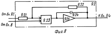
ГСРП 9 предназначен для формирования импульса с равномерным законом распределения на временном интервале ]0,T[.
Схема ГСРП 9, реализующая такие задачи в заявляемом устройстве, приведена на фиг. 6. ГСРП 9 состоит из источника шума (ИШ) 9.1, фиксатора мгновенных значений напряжения (ФМЗ) 9.2, генератора линейно-изменяющегося напряжения (ГЛИН) 9.3, компаратора 9.4, линии задержки (ЛЗ) 9.5 и элемента ЗАПРЕТ 9.6. Информационный вход ФМЗ 9.2 подключен к выходу ИШ 9.1. Выход ФМЗ 9.2 подключен к первому входу компаратора 9.4. Выход ГЛИН 9.3 подключен к второму входу компаратора 9.4. Вход ГСРП 9 подключен одновременно к входу ГЛИН 9.3 и управляющему входу ФМЗ 9.2. Инверсный вход элемента ЗАПРЕТ 9.6 через ЛЗ 9.5 подключен к выходу компаратора 9.4. Прямой вход элемента ЗАПРЕТ 9.6 непосредственно подключен к выходу компаратора 9.4. Выход элемента ЗАПРЕТ 9.6 является выходом ГРСИ 9.
ФМЗ 9.2 предназначен для запоминания в течение заданного промежутка времени мгновенных значений напряжения, поступающих с выхода ИШ 9.1. Схема такого ФМЗ 9.2 известна и его работа описана, например, в [7, с. 46, рис. 2.6]. В заявляемом ГСРП 9 с учетом особенностей взаимосвязей с другими элементами схема ФМЗ 9.2 приобретает вид, показанный на фиг. 8, и включает первый резистор 9.21, первый вывод которого является информационным входом ФМЗ 9.2, а второй подключен одновременно к первому выводу второго резистора 9.22 и прямому входу элемента ЗАПРЕТ 9.23, на инверсный вход которого подключен управляющий вход ФМЗ 9.2. Выход элемента ЗАПРЕТ 9.23 одновременно подключен к первому выводу конденсатора 9.24 и к входу усилителя постоянного тока (УПТ) 9.25. Выход УПТ 9.25 соединен с вторыми выводами второго резистора 9.22 и конденсатора 9.24, а также с выходом ФМЗ 9.2. FMZ 9.2 is intended for storing for a given period of time the instantaneous voltage values coming from the output of IS 9.1. The scheme of such FMZ 9.2 is known and its work is described, for example, in [7, p. 46, fig. 2.6]. In the claimed
D-триггер 15 предназначен для формирования сигнала начала процесса управления передачей пакета данных с l-м приоритетом по синхросигналам, поступающим с выхода синхронизатора 16 на его D-вход, и притом только тогда, когда на его C-входе присутствует потенциал напряжения, соответствующий напряжению логической единицы. D-flip-
Схема построения D-триггера 15, реализующая такие задачи в заявляемом устройстве, известна и описана, например, в [18, с. 172 - 174, рис. 6.6 в]. The construction scheme of the D-
ДИ 10 предназначен для выдачи по сигналу поступающей на его вход одиночной серии импульсов, которая содержит ровно m импульсов, вырезанных из непрерывной последовательности тактовых импульсов, поступающих с задающего генератора.
Схема построения ДИ 10, реализующая такие задачи в заявляемом устройстве, известна и описана, например, в [8, c. 273, рис. 9.11а]. С учетом взаимосвязей с другими элементами схема ДИ 10 принимает вид, показанный на фиг. 9. The construction scheme of
ДИ 10 содержит задающий генератор (ЗГ) 10.1, элемент ЗАПРЕТ 10.2, двоичный счетчик (ДС) 10.3. Выход ЗГ 10.1 подключен к прямому входу элемента ЗАПРЕТ 10.2. Выход элемента ЗАПРЕТ 10.2 является одновременно выходом ДИ 10 и суммирующим входом ДС 10.3. Вход ДИ 10 подключен к R-входу ДС 10.3, выход которого подключен к инверсному входу элемента ЗАПРЕТ 10.2.
Счетчик 13 предназначен для выдачи на его выходе одиночного импульса в момент поступления последнего тактового импульса из серии m импульсов на его вход. Схема построения счетчика 13, реализующая такие задачи в заявляемом устройстве, известна и описана, например, в [8, с. 265 - 266, рис. 9.8а]. С учетом взаимосвязей с другими элементами схема счетчика 13 принимает вид, показанный на фиг. 10. The
Синхронизатор (Cн) 16 предназначен для поддержания тактовой синхронизации между синхронизаторами устройств управления передачей ПД установок пакетной радиосвязи по сигналам синхронизации, передаваемым одной из УПР. The synchronizer (Cn) 16 is designed to maintain clock synchronization between the synchronizers of the control devices for transmitting PD of packet radio communication installations by synchronization signals transmitted by one of the controllers.
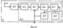
Схема построения синхронизатора 16 с такими функциями в заявляемом устройстве известна, принцип работы и ее расчет приведены соответственно в [5, с. 17 - 30] и [6, с. 3 - 9]. С учетом особенностей взаимосвязей с другими элементами устройства схема Cн 16 преобретает вид, представленный на фиг. 11. В качестве радиоприемного устройства можно использовать, например, радиоприемник P - 160п [12], который имеет режим приема сигналов синхронизации и выдачи на линейный выход соответствующей последовательности импульсов синхронизации. The design of the
Схема Cн 16 включает радиоприемное устройство (ПРМ) 16.2 с антенной 16.1, выход которого подключен на вход дискретной следящей системы с управляемым делителем (ДСС) 16.3. В свою очередь ДСС 16.3 содержит удвоитель частоты 16.4, на вход которого подключен выход ПРМ 16.2, а выход - к первому входу фазового дискреминатора (ФД) 16.5. Выход ФД 16.5 подключен к входу усреднителя 16.6. Выход усреднителя 16.6 подключен к первому входу управляемого устройства 16.7 (УУ). Выход УУ 16.7 подключен на вход УД 16.8. Выход генератора 16.9 подключен к входу УУ 16.7. На второй вход ФД 16.5 и на выход Cн 16 подключен выход УД 16.8.
Cн 16 работает следующим образом. ПРМ 16.1 осуществляет прием на известной частоте сигналов синхронизации и выдает на своем линейном выходе последовательность импульсов сигналов синхронизации (ПСС). Далее ПСС поступает на вход ДСС 16.4. В ДСС 16.4 происходит слежение за эталонной частотой сигналов синхронизации и ее подстройка в случае ухода частоты, обеспечивая тем самым постоянную частоту следования ПСС.
БС 6 предназначен для выдачи сигнала разрешения включения передатчика в случае, если на его обеих входах произошло совпадение во времени двух входных сигналов.
Схема построения БС 6, реализующая такую функцию в заявляемом устройстве, известна и описана, например, в [8, с. 14, рис. 1.2] и может быть реализована на элементе И выполняющую логическую операцию - конъюнкцию. The construction scheme of
Первый 7 и второй 12 элементы ЗАПРЕТ предназначены для формирования на его выходе логической единицы только при одновременном присутствии на его инверсном входе логического нуля, а на прямом входе - логической единицы. Принципиальная схема данного элемента приведена на фиг. 12. The first 7 and second 12 elements of the PROHIBITION are intended to form a logical unit at its output only if there is a logical zero at its inverse input and a logical unit at its direct input. A schematic diagram of this element is shown in FIG. 12.
Схема элемента ЗАПРЕТ включает элемент НЕ 1 и элемент И 2. Вход элемента НЕ 1 и второй вход элемента И 2 являются соответственно инверсным и прямым входами элемента ЗАПРЕТ. Выход элемента НЕ 1 соединен с первым входом элемента И 2, выход которого является выходом элемента ЗАПРЕТ. The circuit of the element FORBID includes the element NOT 1 and the element AND 2. The input of the element NOT 1 and the second input of the element AND 2 are respectively the inverse and direct inputs of the element FORBID. The output of the element NOT 1 is connected to the first input of the element AND 2, the output of which is the output of the element BAN.
Все остальные элементы, входящие в общую (фиг. 2) и частные (фиг. 3, 7, 8, 9, 11, 12) схемы заявляемого устройства известны. Принцип работы и схема элемента ИЛИ приведены в [8, с. 15, рис. 3.1], элемента И - в [8, с. 14, рис. 1.2] , дешифратора - в [8, с. 87 - 89, рис. 3.1], задающего генератора 10.1 - в [8, с. 240 - 241, рис. 7.9 в]; счетчика - в [8; с. 252 - 253; рис. 9.1]; RS-триггера в [8; с. 166 - 172, рис. 6.1]. All other elements included in the general (Fig. 2) and private (Fig. 3, 7, 8, 9, 11, 12) circuits of the claimed device are known. The principle of operation and the circuit of the OR element are given in [8, p. 15, fig. 3.1], the element And - in [8, p. 14, fig. 1.2], the decoder - in [8, p. 87 - 89, fig. 3.1], the master oscillator 10.1 - in [8, p. 240 - 241, Fig. 7.9 in]; counter - in [8; from. 252 - 253; fig. 9.1]; RS-trigger in [8; from. 166 - 172, fig. 6.1].
Заявляемое устройство работает следующим образом. The inventive device operates as follows.
В исходном состоянии осуществляется контроль внешнего сигнала занятости КОП, например сигнал несущего колебания на частоте приема-передачи на первом 7 и втором 12 элементах ЗАПРЕТ. Синхронизатор 16 формирует тактовые синхроимпульсы с периодом следования T. Синхроимпульсы с входа синхранизатора 16 постоянно поступают на D-вход D-триггера 15. RS-триггера 14 находится в нулевом состояние. In the initial state, the external busy signal of the CPC is monitored, for example, a carrier wave signal at the frequency of reception and transmission at the first 7 and second 12 BAN elements. The
При поступлении с информационного входа 17 устройства на первый вход второго элемента ИЛИ 1 ПД, допустим, с 1-м приоритетом одновременно на вход ЗАПРОС ПРД 21 должен поступить внешний сигнал в виде импульса с высоким уровнем напряжения (равный уровню логической "1") на запуск устройства в целом. По этой команде RS-триггер 14 переходит в единичное состояние, выдавая на своем прямом выходе высокий уровень напряжения, равный уровню логической "1". Далее логическая "1" поступает на C-вход D-триггера 15, который превращает последний в "прозрачный" D-триггер. В этом случае логическое состояние на выходе D-триггера 15 будет определяться только сигналами (а именно синхросигналами), поступающими на его D-вход. Сформированный таким образом импульс в момент прихода на D-вход D-триггера 14 очередного синхроимпульса через первый элемент ИЛИ 11 поступает на вход ДИ 10. По этой команде на выходе последнего формируется одна серия тактовых импульсов, число которых равно m. Полученные таким образом тактовые импульсы поступают на считывающий вход РС 2. Таким образом происходит запись ПД l-го приоритета с информационного входа 17 в ячейки памяти РС 2. Под воздействием сформированной серии тактовых импульсов поступает на вход счетчика 13. В момент поступления последнего m-го импульса данной серии в последнем будет сформирован импульс, который поступит на прямой вход второго элемента ЗАПРЕТ 12. Upon receipt from the information input 17 of the device to the first input of the second element OR 1 PD, for example, with the 1st priority, an external signal in the form of a pulse with a high voltage level (equal to the logic level “1”) must be simultaneously input to the REQUEST PRD 21 devices in general. By this command, the RS-
При появлении внешнего C3 или сигнала несущей в первом 7 и втором 12 элементах ЗАПРЕТ блокируются выходы: в первом 7 элементе ЗАПРЕТ - выход 21 сигналов управления ВКЛ ПРД, а во втором 9 элементе ЗАПРЕТ - сигнал запуска процесса управления передачей ПД. When an external C3 or carrier signal appears in the first 7 and second 12 PROHIBIT elements, the outputs are blocked: in the first 7 PROHIBIT element - the output of 21 control signals ON PRD, and in the second 9 element PROHIBIT - the signal to start the process of controlling the transmission of PD.
Допустим, что CЗ в КОП, а следовательно, и на входе 19 отсутствует. Тогда импульс с выхода счетчика 13 через второй элемент ЗАПРЕТ 12 поступит на считывающий вход БСч 3. По этому сигналу произойдет перезапись двоичного кода из j-й ячейки по j + n-ю ячейку на вход Дш 4. Далее двоичный код в Дш 4 преобразуется в унарный, т.е. из всех выходов Дш 4 активный уровень логической "единицы" будет сформирован на одном, а именно на том, номер приоритета которого равен поданному на вход двоичному коду. Тогда двоичный код l-го приоритета преобразуется в ДШ 4 в унарный код и будет присутствовать только на его l-м выходе, т.е. будет высокий уровень напряжения, а на всех остальных выходах ДШ 4 уровень напряжения будет низкий (равный уровню напряжения логического "нуля"). Сформированный таким образом на l-м выходе ДШ 4 сигнал логической "единицы" поступает на соответствующий вход ФДИ 5 и L-входового элемента ИЛИ 8. ФДИ 4 сгенерирует длинный импульс ΔT1 , где 0<ΔT1<T ; l ∈ {1, 2, ..., L}. Длительность данного импульса однозначно соответствует только l-му приоритету ПД. L-входовой элемент ИЛИ 8 выдаст сигнал на запуск ГСРП 9. Этот сигнал одновременно поступит на управляющий вход ФМЗ 9.2, на выходе которого произойдет (фиг. 7d) запоминание напряжения (фиг. 7b), соответствующее в этот момент времени мгновенному значению напряжения шума на выходе ИШ 9.1 (фиг. 7а). Одновременно запускается ГЛИН 9.6. В момент равенства напряжений на выходах ГЛИН 9.6 (фиг. 7с) и ФМЗ 9.2 (фиг. 7 b) срабатывает компаратор 9.3. В результате на выходе компаратора 9.3 формируется импульс (фиг. 7 е) с уровнем напряжения, равным уровню логической "1", и длительностью с равномерным законом распределения на временном интервале ]0. T[. Это объясняется тем, что выборка мгновенных значений напряжений из реализации случайного процесса ИШ 9.1 равномерно распределена в некотором интервале напряжений шума. Полученный импульс со случайной длительностью поступает на прямой вход элемента ЗАПРЕТ 9.6 и на вход ЛЗ 9.5. В ЛЗ 9.5 импульс задерживается на величину Δtc . Далее с выхода ЛЗ 9.5 импульс поступает на инверсный вход элемента ЗАПРЕТ 9.6. Известно, что элемент ЗАПРЕТ 9.6 формирует на своем выходе логическую единицу только при одновременном присутствии на своем инверсном входе логического нуля (фиг. 7 f), а на прямом входе - логической единицы (фиг. 7 e). Таким образом, на выходе ГСРП 9 будут формироваться импульсы длительностью Δtc (фиг. 7 n), нахождение которых в интервале ]0,T[ равновероятно.Assume that C3 in the CPC, and therefore, at
Полученные таким образом длинный импульс ΔTl/ и равномерно распределенный импульс Δtc поступают на входы БС 6. В случае не совпадения во времени на выходе БС 6 будет отсутствовать сигнал ВКЛ ПРД и до окончания времени текущего такта функционирования сети ПРС никакие действия в устройстве происходить не будут. С началом следующего такта работы ПРС синхронизатор 16 снова выдаст очередной синхроимпульс. Данный синхроимпульс поступит на D-вход, и процесс, описанный выше, повторится, начиная с момента формирования одиночной серии m-импульсов.The long pulse ΔT l / thus obtained and the uniformly distributed pulse Δt c are fed to the inputs of
Если произошло совпадение во времени длинного импульса ΔT1 и равномерно распределенного импульса Δtc с выхода БС 6 на прямой вход первого элемента ЗАПРЕТ 7 будет подан сигнал разрешения передачи ПД. Если на инверсный вход первого элемента ЗАПРЕТ 7 поступит внешний C3, то последний не сформирует сигнал ВКЛ ПРД и процесс управления передачей ПД повторится аналогично описанному выше с той лишь разницей, что внешний C3 будет присутствовать и на инверсном входе второго элемента ЗАПРЕТ 12.If there is a coincidence in time of a long pulse ΔT 1 and a uniformly distributed pulse Δt c from the output of
В случае свободного канала связи общего пользования, а следовательно, и отсутствия на входе 19 внешнего C3, на выходе первого элемента ЗАПРЕТ 7 будет сформирован сигнал ВКЛ ПРД. Данный сигнал поступит на выход сигнала управления 21 ВКЛ ПРД, на первый вход элемента ИЛИ 11 и далее на вход ДИ 10. В ДИ 10 опять сформируется одиночная серия тактовых импульсов и поступит на считывающий вход РС 2. В РС 2 произойдет считывание ПД с l-м приоритетом на информационный выход 18 и одновременная его перезапись по цепи обратной связи на информационный вход 17. Оставшееся время на текущем такте работы сети ПРС равным времени tож (где T=tпр+tож; tпр - время передачи; tож - время ожидания КВИТАНЦИИ) осуществляется прием подтверждения приема ПД с l-м приоритетом.In the case of a free communication channel for general use, and, consequently, the absence of external C3 at
Если сигнал КВИТАНЦИЯ не получен, то процесс повторной передачи ПД аналогичен выше описанному, начиная со следующего такта. Для этого случая и служит обратная связь в РС 2 для сохранения ПД с l-приоритетом для последующей передачи. If the RECEIPT signal has not been received, then the process of retransmitting the AP is similar to that described above, starting from the next measure. For this case, feedback in
В противном случае сигнал "Квитанция" поступит на установочный вход РС 2, на R-вход RS-триггера 15 и на R*-вход D-триггера 15. В первом происходит обнуление ячеек памяти, а во втором и третьем - перевод в нулевое состояние.Otherwise, the “Receipt” signal will go to the installation input of
Проведем сравнительный анализ известного способа управления передачей ПД в канал связи общего пользования и заявляемого. Для проведения такого исследования воспользуемся известной методикой [13], в которой в качестве обобщенного показателя качества информационного объема ПД в сетях радиосвязи с коммутации пакетов использована вероятностно-временная характеристика пребывания сообщения (пакета данных) в канале связи общего пользования. Let us conduct a comparative analysis of the known method for controlling the transmission of PD to the public communication channel and the claimed one. To carry out such a study, we will use the well-known method [13], in which the probability-time characteristic of the message (data packet) being in the public communication channel is used as a generalized indicator of the quality of the information volume of PD in radio networks with packet switching.
Функция распределения времени пребывания пакета данных Tпд можно представить в компактной форме как
FTпд(t)=P(Tпд≤t).The distribution function of the residence time of the data packet T PD can be represented in a compact form as
F Tpd (t) = P (T pd ≤t).
Вследствие пуассоновского характера потока передачи ПД в пакетной радиосети интервалы времени между поступлением соседних пакетов данных являются случайными величинами с показательной функцией распределения [13, 1 с. 16]. С учетом этого утверждения функция распределения FTпд(t) будет выглядеть следующим образом:
FTпд(t)=P(Tпд≤t)=1-exp(- νt t),
где
ν - среднее число пакетов данных, передаваемых в единицу времени.Due to the Poisson nature of the PD transmission stream in a packet radio network, the time intervals between the arrival of neighboring data packets are random variables with an exponential distribution function [13, 1 p. sixteen]. With this statement in mind, the distribution function F Tpd (t) will look like this:
F Tpd (t) = P (T pd ≤t) = 1-exp (- νt t),
Where
ν is the average number of data packets transmitted per unit time.
Анализ заявляемого и известного способов управления передачей ПД в КОП будет проводить в ситуации высокой информационной нагрузки, являющейся наихудшей в функционировании пакетной радиосети, при которой на все УПР сети одновременно поступили ПД для передачи. В этих условиях в КОП происходит наибольшее количество конфликтов между УПР в канале связи общего пользования. В этой ситуации вероятность успешной передачи ПД i-й УПР в текущем такте работы сети определяется выражением [11, с. 78]

где
pi - вероятность передачи ПД в КОП i-й УПР сети.An analysis of the claimed and known methods for controlling the transmission of PDs to the CPC will be carried out in a situation of high information load, which is the worst in the operation of a packet radio network, in which PDs for transmission are simultaneously received on all RNM networks. Under these conditions, in the CPC there is the greatest number of conflicts between the UPR in the public communication channel. In this situation, the probability of successful transmission of the PD of the i-th control in the current cycle of the network is determined by the expression [11, p. 78]
Where
p i - the probability of transmitting PD to the CPC of the i-th control network.
Если известна скорость передачи R, то с учетом выражения (3) можно определить среднее время передачи пакета данных заданного объема V
T
а среднее число пакетов данных, передаваемых в единицу времени, найти из выражения
ν = 1/T
Для упрощения расчетов положим, что в ПРС развернуто 9 установок пакетной радиосвязи. По первому способу при передаче ПД не учитываются приоритеты, а по заявляемому способу при передаче ПД происходит учет категорий срочности. Кроме того, считываем объем пакета данных V и скорость передачи R равный 1, ПД 1-й, 2-й и 3-й категорий поступает соответственно только каждой третий УПР от общего количества.If the transmission rate R is known, then taking into account expression (3), we can determine the average transmission time of a data packet of a given volume V
T
and the average number of data packets transmitted per unit time is found from the expression
ν = 1 / T
To simplify the calculations, we assume that 9 packet radio communication installations are deployed in the ORS. According to the first method, when transferring PDs, priorities are not taken into account, and according to the claimed method when transmitting PDs, categories of urgency are recorded. In addition, we read the volume of the data packet V and the transmission rate R equal to 1, PD of the 1st, 2nd, and 3rd categories, respectively, comes only for every third UPR of the total.
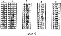
На фиг. 13 приведены графики функции распределения FTпд(t) для анализируемых способов. Расчеты проводились по выражениям (2)-(5). Сопоставление графиков на фиг. 13 и таблиц на фиг. 14 показывает, что УПР, использующая заявляемый способ передачи пакетов данных в КОП, имеет лучшие ВВХ по сравнению с известным. Это объясняется тем, что сигнал разрешения передачи для ПД со старшими приоритетами имеет большую вероятность формирования, чем сигнал для младших приоритетов при всех других равных условиях. Это позволяет в конечном счете добиться более высокой пропускной способности канала связи общего пользования при передаче пакетов данных различной срочности в условиях высокой информационной нагрузки.In FIG. 13 shows graphs of the distribution function F Tpd (t) for the analyzed methods. The calculations were performed according to expressions (2) - (5). The graph comparison in FIG. 13 and the tables of FIG. 14 shows that the UPR using the inventive method of transmitting data packets to the CPC, has the best VVH compared with the known. This is because the transmission enable signal for PDs with higher priorities has a higher probability of formation than the signal for lower priorities, with all other conditions being equal. This allows ultimately to achieve a higher bandwidth of the public communication channel when transmitting data packets of various urgency in conditions of high information load.
Список источников информации:
1. Электросвязь, N 9, 1994.List of sources of information:
1. Telecommunications,
2. Бунин С.Г., Войтер А.П. Вычислительные сети с пакетной радиосвязью. К.: Техника, 1989, с. 223. 2. Bunin S.G., Voiter A.P. Packet radio computing networks. K .: Technique, 1989, p. 223.
3. А.С. N 1162057, H 04 L 7/00 Б.И. 22.85. 3. A.S. N 1162057, H 04
4. А.С. N 1162058, H 04 L 7/00 Б.И. 22.85. 4. A.S. N 1162058, H 04
5. Бухвинер В. Е. Дискретные схемы в фазовых системах радиосвязи. М.: Связь, 1969, 144 с. 5. Bukhviner V. E. Discrete circuits in phase radio communication systems. M .: Communication, 1969, 144 p.
6. Бухвинер В.Е. Расчет дискретной системы синхронизации/ Электросвязь, 1962, N 6, с. 3-10. 6. Bukhviner V.E. Calculation of a discrete synchronization system / Telecommunication, 1962,
7. Бобнев М.П. Генерирование случайных сигналов. М.: Энергия, 1971, с. 240. 7. Bobnev M.P. Random signal generation. M .: Energy, 1971, p. 240.
8. Потемкин И.С. Функциональные узлы цифровой автоматики. - М.: Энергоатомиздат, 1988. - 300 с.: ил. [9]
9. Микросхемы и их применение: Справочное пособие/ В.А. Батушев и др. - М.: Радио и связь, 1983 - 272 с. (Массовая радиобиблиотека; вып. 1070).8. Potemkin I.S. Functional units of digital automation. - M.: Energoatomizdat, 1988 .-- 300 p .: ill. [nine]
9. Microcircuits and their application: Reference manual / V.A. Batushev et al. - M.: Radio and Communications, 1983 - 272 p. (Mass Radio Library; issue 1070).
10. Радио, N 9, 1990. 10. Radio,
11. Проблемы передачи информации, том XV, вып. 4, 1979. 11. Problems of Information Transfer, Volume XV, no. 4, 1979.
12. Радиоприемник Р-160п: Техническое описание и инструкция по эксплуатации, ЦЛ2.003.067 ТО, Омск, 1987. 12. Radio receiver R-160p: Technical description and operating instructions, TSL2.003.067 TO, Omsk, 1987.
13. Сети радиосвязи с пакетной передачей информации. А.Н. Шаров и др./ Под ред. А.Н. Шарова. СПб.: ВАС, 1994, с. 216. 13. Radio communication networks with packet information transfer. A.N. Sharov et al. / Ed. A.N. Sharova. SPb .: YOU, 1994, p. 216.
Claims (3)
3. Способ по п.1, отличающийся тем, что при приеме пакета данных с l-м приоритетом дополнительно на соответствующей установке пакетной радиосвязи формируют сигнал подтверждения его приема, передают сигнал подтверждения, а при отсутствии сигнала подтверждения действия по управлению передачей пакета данных с l-м приоритетом повторяют.2. The method according to claim 1, characterized in that the duration of the random pulse Δt c is selected in the range Δt c = (0.05 ... 0.1) (T / L).
3. The method according to claim 1, characterized in that when receiving a data packet with the l-th priority, a confirmation signal for receiving it is additionally generated on the corresponding packet radio installation, a confirmation signal is transmitted, and in the absence of a confirmation signal, actions to control the transmission of the data packet with l -th priority is repeated.
Priority Applications (1)
| Application Number | Priority Date | Filing Date | Title |
|---|---|---|---|
| RU97105517A RU2115246C1 (en) | 1997-04-07 | 1997-04-07 | Method of transmission of data packs in general- purpose communication channel and control device |
Applications Claiming Priority (1)
| Application Number | Priority Date | Filing Date | Title |
|---|---|---|---|
| RU97105517A RU2115246C1 (en) | 1997-04-07 | 1997-04-07 | Method of transmission of data packs in general- purpose communication channel and control device |
Publications (2)
| Publication Number | Publication Date |
|---|---|
| RU2115246C1 true RU2115246C1 (en) | 1998-07-10 |
| RU97105517A RU97105517A (en) | 1998-11-27 |
Family
ID=20191678
Family Applications (1)
| Application Number | Title | Priority Date | Filing Date |
|---|---|---|---|
| RU97105517A RU2115246C1 (en) | 1997-04-07 | 1997-04-07 | Method of transmission of data packs in general- purpose communication channel and control device |
Country Status (1)
| Country | Link |
|---|---|
| RU (1) | RU2115246C1 (en) |
Cited By (12)
| Publication number | Priority date | Publication date | Assignee | Title |
|---|---|---|---|---|
| US8023950B2 (en) | 2003-02-18 | 2011-09-20 | Qualcomm Incorporated | Systems and methods for using selectable frame durations in a wireless communication system |
| US8081598B2 (en) | 2003-02-18 | 2011-12-20 | Qualcomm Incorporated | Outer-loop power control for wireless communication systems |
| US8150407B2 (en) | 2003-02-18 | 2012-04-03 | Qualcomm Incorporated | System and method for scheduling transmissions in a wireless communication system |
| US8201039B2 (en) | 2003-08-05 | 2012-06-12 | Qualcomm Incorporated | Combining grant, acknowledgement, and rate control commands |
| US8391249B2 (en) | 2003-02-18 | 2013-03-05 | Qualcomm Incorporated | Code division multiplexing commands on a code division multiplexed channel |
| US8477592B2 (en) | 2003-05-14 | 2013-07-02 | Qualcomm Incorporated | Interference and noise estimation in an OFDM system |
| US8526966B2 (en) | 2003-02-18 | 2013-09-03 | Qualcomm Incorporated | Scheduled and autonomous transmission and acknowledgement |
| US8548387B2 (en) | 2003-03-06 | 2013-10-01 | Qualcomm Incorporated | Method and apparatus for providing uplink signal-to-noise ratio (SNR) estimation in a wireless communication system |
| US8576894B2 (en) | 2003-03-06 | 2013-11-05 | Qualcomm Incorporated | Systems and methods for using code space in spread-spectrum communications |
| US8699452B2 (en) | 2003-02-18 | 2014-04-15 | Qualcomm Incorporated | Congestion control in a wireless data network |
| RU2523359C2 (en) * | 2003-02-18 | 2014-07-20 | Квэлкомм Инкорпорейтед | Scheduled and autonomous transmission and acknowledgement |
| US9998379B2 (en) | 2003-02-18 | 2018-06-12 | Qualcomm Incorporated | Method and apparatus for controlling data rate of a reverse link in a communication system |
-
1997
- 1997-04-07 RU RU97105517A patent/RU2115246C1/en active
Non-Patent Citations (1)
| Title |
|---|
| Бунин С.Г., Войтер А.П. Вычислительные сети с пакетной радиосвязью. - Тех ника, 1989, с.57. * |
Cited By (16)
| Publication number | Priority date | Publication date | Assignee | Title |
|---|---|---|---|---|
| US8699452B2 (en) | 2003-02-18 | 2014-04-15 | Qualcomm Incorporated | Congestion control in a wireless data network |
| US8081598B2 (en) | 2003-02-18 | 2011-12-20 | Qualcomm Incorporated | Outer-loop power control for wireless communication systems |
| US8150407B2 (en) | 2003-02-18 | 2012-04-03 | Qualcomm Incorporated | System and method for scheduling transmissions in a wireless communication system |
| US9998379B2 (en) | 2003-02-18 | 2018-06-12 | Qualcomm Incorporated | Method and apparatus for controlling data rate of a reverse link in a communication system |
| US8391249B2 (en) | 2003-02-18 | 2013-03-05 | Qualcomm Incorporated | Code division multiplexing commands on a code division multiplexed channel |
| US8977283B2 (en) | 2003-02-18 | 2015-03-10 | Qualcomm Incorporated | Scheduled and autonomous transmission and acknowledgement |
| RU2523359C2 (en) * | 2003-02-18 | 2014-07-20 | Квэлкомм Инкорпорейтед | Scheduled and autonomous transmission and acknowledgement |
| US8526966B2 (en) | 2003-02-18 | 2013-09-03 | Qualcomm Incorporated | Scheduled and autonomous transmission and acknowledgement |
| US8023950B2 (en) | 2003-02-18 | 2011-09-20 | Qualcomm Incorporated | Systems and methods for using selectable frame durations in a wireless communication system |
| US8548387B2 (en) | 2003-03-06 | 2013-10-01 | Qualcomm Incorporated | Method and apparatus for providing uplink signal-to-noise ratio (SNR) estimation in a wireless communication system |
| US8676128B2 (en) | 2003-03-06 | 2014-03-18 | Qualcomm Incorporated | Method and apparatus for providing uplink signal-to-noise ratio (SNR) estimation in a wireless communication system |
| US8576894B2 (en) | 2003-03-06 | 2013-11-05 | Qualcomm Incorporated | Systems and methods for using code space in spread-spectrum communications |
| US8705588B2 (en) | 2003-03-06 | 2014-04-22 | Qualcomm Incorporated | Systems and methods for using code space in spread-spectrum communications |
| US8477592B2 (en) | 2003-05-14 | 2013-07-02 | Qualcomm Incorporated | Interference and noise estimation in an OFDM system |
| US8489949B2 (en) | 2003-08-05 | 2013-07-16 | Qualcomm Incorporated | Combining grant, acknowledgement, and rate control commands |
| US8201039B2 (en) | 2003-08-05 | 2012-06-12 | Qualcomm Incorporated | Combining grant, acknowledgement, and rate control commands |
Similar Documents
| Publication | Publication Date | Title |
|---|---|---|
| US4536875A (en) | Retransmission control system | |
| RU2115246C1 (en) | Method of transmission of data packs in general- purpose communication channel and control device | |
| EP0615363B1 (en) | Wireless local area network apparatus | |
| US4506361A (en) | Retransmission control system | |
| GB1565562A (en) | Data communication system | |
| RU94045877A (en) | METHOD FOR REDUCING COLLISIONS BETWEEN MESSAGES IN A COMMUNICATION NETWORK AND DEVICE DEVICE FOR ITS IMPLEMENTATION | |
| EP0088906B1 (en) | Apparatus for providing transmitter hierarchy control for efficient use of a common channel by a plurality of users | |
| US4813012A (en) | Terminal access protocol circuit for optical fiber star network | |
| US5684802A (en) | System and method for hybrid contention/polling protocol collison resolution used backoff timers with polling | |
| US6516364B1 (en) | Method for time coordination of the transmission of data on a bus | |
| RU97105517A (en) | METHOD AND DEVICE FOR MANAGING THE TRANSMISSION OF DATA PACKAGES IN THE COMMUNICATION CHANNEL | |
| RU2137312C1 (en) | Method and device controlling transmission of data package over common-user communication channel | |
| CA1257936A (en) | Method of transmitting information in a digital transmission system | |
| Rubin | Synchronous and channel-sense asynchronous dynamic group-random-access schemes for multiple-access communications | |
| SU1401626A1 (en) | System for radio communication with mobile objects | |
| RU2050695C1 (en) | Central station of system for radio communication with mobile objects | |
| Andersson et al. | Static-priority scheduling of sporadic messages on a wireless channel | |
| JPH0358205B2 (en) | ||
| SU1083382A1 (en) | Device for transmitting and receiving information | |
| SU1162058A1 (en) | Device for controlling data transmission via radiocommunication channel | |
| RU2382499C1 (en) | Method for radio communication between mobile objects | |
| RU2127488C1 (en) | Phase-lead synchronization method and device for mobile radio communication systems | |
| JPH0423525A (en) | Radio packet multiple address communication control system | |
| KR950001514B1 (en) | Local area network communications device using common bus | |
| RU2010434C1 (en) | Satellite communication system |