RU2110077C1 - Method determining course angle and coordinates of locations of objects by radio signals of spacecraft of satellite radio navigation systems - Google Patents
Method determining course angle and coordinates of locations of objects by radio signals of spacecraft of satellite radio navigation systems Download PDFInfo
- Publication number
- RU2110077C1 RU2110077C1 RU94031143A RU94031143A RU2110077C1 RU 2110077 C1 RU2110077 C1 RU 2110077C1 RU 94031143 A RU94031143 A RU 94031143A RU 94031143 A RU94031143 A RU 94031143A RU 2110077 C1 RU2110077 C1 RU 2110077C1
- Authority
- RU
- Russia
- Prior art keywords
- phase
- antenna
- increments
- navigation
- satellite
- Prior art date
Links
Images

Landscapes
- Position Fixing By Use Of Radio Waves (AREA)
Abstract
Description
Изобретение относится к космической радионавигации, геодезии и может быть использовано для определения курсового угла и координат местоположения объектов. The invention relates to space radio navigation, geodesy and can be used to determine the course angle and the coordinates of the location of objects.
Известен способ определения местоположения и курсового угла объектов по навигационным радиосигналам космических аппаратов (КА) спутниковых радионавигационных систем (СРНС) с использованием измеренных псевдодальностей с помощью четырех антенно-приемных устройств сигналов спутников, антенны которых установлены на объектах таким образом, что они образуют прямоугольную систему координат (Applications of Navstar GPS fo presion attitude determination Roht Ben. D., Singh Ram-Nandan P. "Proc. 4 th. Geod. Symp Sattel. Position., Austin, Tex. 28.Apr.-28 Max, 1986, v.2." S.1, 2, 1345 -1359, прототип). A known method for determining the location and heading angle of objects from the navigation radio signals of spacecraft (SC) of satellite radio navigation systems (SRNS) using measured pseudorange using four antenna receivers of satellite signals, the antennas of which are mounted on objects so that they form a rectangular coordinate system (Applications of Navstar GPS fo presion attitude determination Roht Ben. D., Singh Ram-Nandan P. "Proc. 4 th. Geod. Symp Sattel. Position., Austin, Tex. 28.Apr.-28 Max, 1986, v .2. "S.1, 2, 1345-1359, prototype).
Недостатками этого способа являются:
погрешности навигационных определений обусловленные нестабильностью частот радиосигналов навигационного искусственного спутника Земли (НИСЗ) и генераторов объектов;
погрешности измерений, определений, обусловленных угловым перемещением антенн объектов в процессе их движения.The disadvantages of this method are:
errors in navigation definitions due to the instability of the frequencies of the radio signals of the navigation artificial satellite of the Earth (NIE) and generators of objects;
measurement errors, definitions caused by the angular displacement of the antennas of objects in the process of their movement.
Для оценки точности измерений приращений фаз с использованием CCH используется выражение дисперсии ε

где
λн -длина волны несущей частоты;
Bссн -ширина полосы схемы слежения за несущей;
Pc/Pш - отношение мощности сигнала к спектральной мощности шума;
π = 3,1415... .To evaluate the accuracy of phase increment measurements using CCH, the dispersion expression ε
Where
λ n is the wavelength of the carrier frequency;
B SSN is the bandwidth of the carrier tracking circuit;
P c / P W - the ratio of signal power to spectral noise power;
π = 3.1415 ....
Погрешности измерений приращения фаз, например, на частоте f ≈ 1600 МГц глобальной позиционной системы ( ![]()
![]()
В CPHC материальным носителем информации о взаимном положении и относительном перемещении в пространстве объекта навигации и навигационной точки (НИСЗ) является электромагнитная волна, распространяющаяся в среде между антеннами этих двух объектов. Эта информация содержится в параметрах сигналов, излучаемых навигационными КА, поэтому в CPHC в процессе измерений радионавигационных параметров устанавливается функциональная связь не между КА и определяющимися объектами, положение которых в пространстве определяется положением их центров масс в некоторой системе координат, а между фазовыми центрами антенн объектов и навигационным искусственным спутником Земли (НИСЗ). Следовательно, фазовый центр антенн является точкой отсчета координат местоположение и точкой отсчета навигационного параметра как НИСЗ, так и определяющихся объектов. In CPHC, the material carrier of information about the relative position and relative movement in space of a navigation object and a navigation point (NESS) is an electromagnetic wave propagating in the medium between the antennas of these two objects. This information is contained in the parameters of the signals emitted by the navigation spacecraft; therefore, in the CPHC during the measurement of the radio navigation parameters, a functional relationship is established not between the spacecraft and the determined objects, the position of which in space is determined by the position of their centers of mass in a certain coordinate system, but between the phase centers of the object antennas and artificial navigation satellite of the Earth (NISH). Consequently, the phase center of the antennas is a reference point for the location coordinates and a reference point for the navigation parameter of both the NISS and the detected objects.
Физически фазовый центр - это точка, из которой для наблюдателя, находящегося в дальней зоне антенны, исходят (входят) сферические электромагнитные волны излучаемого (принимаемого) поля. Как известно, сферический волновой фронт электромагнитной волны дают точечные излучатели. Реально на практике антенны в зависимости от рабочего диапазона частот, от конструкции занимает вполне определенный конкретный объем, поэтому определение, например, базы интерферометра как расстояние между антеннами технически некорректно. Точность знания длины базы интерферометра, ее ориентации в пространстве определяют точность определения угловых координат, а в целом точность решения навигационной задачи, определяющимися объектами. Physically, the phase center is the point from which for the observer located in the far zone of the antenna, spherical electromagnetic waves of the emitted (received) field emit (enter). As is known, spherical wavefront of an electromagnetic wave is produced by point emitters. Actually, in practice, antennas, depending on the operating frequency range, on the design, take a well-defined specific volume, therefore, for example, determining the base of an interferometer as the distance between antennas is technically incorrect. The accuracy of knowing the length of the base of the interferometer, its orientation in space determines the accuracy of determining the angular coordinates, and in general the accuracy of solving the navigation problem, determined by objects.
В соответствии с вышеизложенным водится понятие "фазового центра" антенны. Соответственно расстояние между антеннами, являющееся базой радиоинтерферометра, будет определяться как расстояние между фазовыми центрами антенн. In accordance with the foregoing, the concept of the "phase center" of the antenna. Accordingly, the distance between the antennas, which is the base of the radio interferometer, will be determined as the distance between the phase centers of the antennas.
Цель изобретения - повышение точности определения курсового угла и координат местоположения объектов по навигационным радиосигналам КА СРНС. The purpose of the invention is to increase the accuracy of determining the heading angle and the coordinates of the location of objects on the navigation radio signals of the SRNS.
Цель достигается за счет:
новой совокупности действий над принимаемыми спутниковыми радионавигационными сигналами;
выделения в ведущих и ведомых антенно-приемных устройствах интерферометра сигналов с доплеровским смещением частоты путем возведения принятых спутниковых радиосигналов в квадрат и их фильтрации с последующим возвратом частот на искомые с использованием делителей частоты;
измерения на мерном интервале приращений фаз, обусловленных доплеровским сдвигом частоты путем использования квадратурных фазовых детекторов, на первые выходы которых поступают сигналы с доплеровским сдвигом частоты, а на вторые - сигнал опорного генератора;
определения разности хода радиосигналов между фазовым центром антенны спутника и фазовыми центрами антенн интерферометра как разность измеренных на мерном интервале приращений фаз, обусловленных доплеровским смещением частоты.The goal is achieved by:
a new set of actions on received satellite radio navigation signals;
separation of signals with Doppler frequency offset in the leading and slave antenna-receiving devices of the interferometer by squaring the received satellite radio signals and filtering them, followed by returning the frequencies to the desired using frequency dividers;
measurements on the measured interval of phase increments caused by the Doppler frequency shift by using quadrature phase detectors, the first outputs of which receive signals with a Doppler frequency shift, and the second - the signal of the reference generator;
determining the difference in the path of the radio signals between the phase center of the satellite antenna and the phase centers of the antennas of the interferometer as the difference of the phase increments measured on the measured interval due to the Doppler frequency shift.
Геометрическая интерпретация предлагаемого способа поясняется на примере одной ортогональной базы, образованной двумя фазовыми центрами антенн интерферометра ФЦ1 и ФЦ2 и тремя положениями фазового центра одного и того же спутника (фиг.1). The geometric interpretation of the proposed method is illustrated by the example of one orthogonal base formed by two phase centers of the antennas of the interferometer FC1 and FC2 and three positions of the phase center of the same satellite (Fig. 1).
Точками T1, T*, T2 (фиг.1) обозначены положения фазового центра антенны спутника на орбите, являющиеся границами отсчетов навигационного параметра. Использование теоремы косинусов и разложения в ряд с членами не выше второго порядка для трех положений фазового центра антенны НИСЗ, позволяет получить:
для фазового центра ФЦ1 антенны Ан1 определяющегося объекта
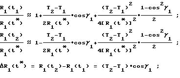
for the phase center FC1 of the antenna An1 of the detected object
для фазового центра ФЦЗ антенны АнЗ
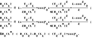
Таким образом, каждая разность хода радиосигналов ΔR1(t*) , ΔR3(t*) дает информацию о проекции пути пройденного фазовым центром антенны НИСЗ из точки T1 в точку T2 на направление прямых R1(t*), R3(t*) соединяющих точку T* (положение фазового центра антенны НИСЗ в момент времени T3) с фазовыми центрами Ан1 и Ан2.Thus, each difference in the path of the radio signals ΔR 1 (t * ), ΔR 3 (t * ) gives information about the projection of the path traveled by the phase center of the NESA antenna from point T 1 to point T 2 on the direction of the lines R 1 (t * ), R 3 (t * ) connecting the point T * (the position of the phase center of the NISS antenna at time T 3 ) with the phase centers An1 and An2.
Вторично используя теорему косинусов и разложения в ряд с членами не выше второго порядка для фазового центра антенны НИСЗ, находящегося в точке T*, позволяет получить

Как отмечалось выше, дальности R1(t*) и R3(t*) содержат в себе проекции пути, пройденные фазовым центром антенны НИСЗ из точки T1 в точку T2. Поэтому, беря разницу расстояний ΔR1,3(t*) = R1(t*)-R3(t*), находим информацию о проекции разности хода радиосигналов между фазовым центром антенны Н НИСЗ, находящегося в точке T* и фазовыми центрами антенны интерферометра определяющегося объекта
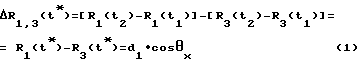
Двойная разность дальностей ΔR1,3(t*) - разность приращений дальности R(t) дает информацию о проекции базового расстояния d1 между фазовыми центрами антенн объекта Ан1, Ан3 на направление прямой R(t*), соединяющей среднюю точку базы с фазовым центром антенны НИСЗ в момент времени T*
![]()
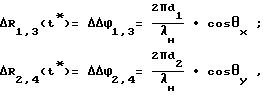
Аналогичным образом выводится соотношение разности приращений дальности для второй ортогональной пары интерферометра

В соответствии с вышеизложенным разностям приращений дальностей - разностям хода радиосигналов между фазовым центром антенны спутника и фазовыми центрами антенн интерферометра в каждой взаимно-ортогональной базе, выражения (1) и (2) соответствуют разности измеренных на мерном интервале приращений фаз,
обусловленных доплеровским смещением частоты
где
cosθx,cosθy - направляющие косинусы.As noted above, the ranges R 1 (t * ) and R 3 (t * ) contain the projection of the path traveled by the phase center of the NHA antenna from point T 1 to point T 2 . Therefore, taking the difference in distances ΔR 1.3 (t * ) = R 1 (t * ) -R 3 (t * ), we find information on the projection of the difference in the path of the radio signals between the phase center of the N NSS antenna located at point T * and phase centers detectable object interferometer antennas
The double range difference ΔR 1.3 (t * ) - the difference in the range increments R (t) gives information about the projection of the base distance d 1 between the phase centers of the antennas of the object An1, An3 on the direction of the line R (t * ) connecting the midpoint of the base with the phase NISS antenna center at time T *
![]()
In a similar way, the ratio of the difference in the distance increments for the second orthogonal pair of the interferometer is derived
In accordance with the aforementioned differences in the increments of ranges - the differences in the path of radio signals between the phase center of the satellite antenna and the phase centers of the antennas of the interferometer in each mutually orthogonal base, expressions (1) and (2) correspond to the difference of the phase increments measured on the measuring interval,
due to Doppler frequency shift
Where
cosθ x , cosθ y are the direction cosines.
Направляющими косинусами cosθx,cosθy,cosθz называются косинусы углов между отрезком R(t*), соединяющим середину базы интерферометра с фазовым центром антенны НИСЗ и положительными направлениями осей OX, OY, OZ соответственно
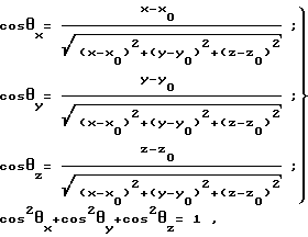
где
X, Y, Z - известные координаты фазового центра антенны спутника;
X0, Y0, Z0 - неизвестные координаты фазового центра антенны определяющегося объекта.The direction cosines cosθ x , cosθ y , cosθ z are the cosines of the angles between the segment R (t * ) connecting the middle of the base of the interferometer with the phase center of the NISS antenna and the positive directions of the axes OX, OY, OZ, respectively
Where
X, Y, Z - known coordinates of the phase center of the satellite antenna;
X 0 , Y 0 , Z 0 - unknown coordinates of the phase center of the antenna of the detected object.
Навигационные измерения с использованием интерферометров, позволяют реализовать азимутальный способ определения координат местоположения объектов, угломерно-дальномерный способ с использованием направляющих косинусов и т.д. Выше приведены функциональные зависимости между известными координатами фазового центра антенны НИСЗ и известными координатами середины баз интерферометра определяющегося объекта через направляющие косинусы
ΔΔφ1,3(t) = Δφ1(t)-Δφ3(t) ,
где
Δψ1(t),Δψ3(t) - приращение фаз, обусловленных доплеровским смещением частоты, измеренные с использованием сигналов первого и третьего антенно-приемных устройств.Navigation measurements using interferometers make it possible to implement an azimuthal method for determining the coordinates of the location of objects, a goniometric-rangefinder method using directing cosines, etc. The above are the functional dependencies between the known coordinates of the phase center of the NISS antenna and the known coordinates of the middle of the bases of the interferometer of the detected object through the direction cosines
ΔΔφ 1,3 (t) = Δφ 1 (t) -Δφ 3 (t),
Where
Δψ 1 (t), Δψ 3 (t) - phase increment due to Doppler frequency shift, measured using the signals of the first and third antenna-receiving devices.
Разность хода спутникового навигационного радиосигнала принятых антенно-приемными устройствами каждой взаимно-ортогональной парой интерферометра называют разность аргументов синусоидальной или косинусоидальной функции, описывающей этот сигнал. The difference in the travel of the satellite navigation radio signal received by the antenna-receiving devices by each mutually orthogonal pair of the interferometer is called the difference in the arguments of the sinusoidal or cosine function that describes this signal.
В общем случае он содержит несколько составляющих, обусловленных различными причинами. Так, в гармоническом колебании вида
u = Ucos[ωt+φ(t)+φнач],
имеем
ωt - линейно нарастающую фазу;
φ(t) - детерминированную или случайную функцию, отображающую процесс фазовой модуляции или действия помех;
φнач - начальную фазу, т.е. фазу при t=0,φ(t)=0.
В соответствии с изложенным принимаемые спутниковый навигационный сигнал первым и третьим антенно-приемными устройствами интерферометра можно описать выражениями:
![]()
где t1, t3 - время распространения навигационного сигнала от фазового центра антенн НИСЗ до фазовых центров антенн АН1, Ан3 соответственно
Fy1, Fy3 - доплеровские сдвиги частот, принятые первым и третьим антенно-приемными устройствами соответственно;
fн - несущая частота.In the general case, it contains several components due to various reasons. So, in the harmonic vibration of the form
u = Ucos [ωt + φ (t) + φ beg ],
we have
ωt is a linearly increasing phase;
φ (t) is a deterministic or random function that displays the process of phase modulation or interference;
φ nach - initial phase, i.e. phase at t = 0, φ (t) = 0.
In accordance with the above, the received satellite navigation signal by the first and third antenna-receiving devices of the interferometer can be described by the expressions:
![]()
where t 1 , t 3 - propagation time of the navigation signal from the phase center of the NISS antennas to the phase centers of the antennas AN1, An3, respectively
F y1 , F y3 - Doppler frequency shifts received by the first and third antenna-receiving devices, respectively;
f n - carrier frequency.
Несущая частота - частота гармонического колебания, подвергающая модуляции с целью передачи информации. Carrier frequency - the frequency of harmonic oscillations, subject to modulation in order to transmit information.
Разность хода сигналов принятых антенно-приемными устройствами интерферометра можно измерить и по разности фаз несущей fн, тогда требуется знание составляющих 2πFд и по разности фаз доплеровских смещений частоты, тогда требуется знание составляющей 2πfн.The difference in the signal paths received by the antenna-receiving devices of the interferometer can also be measured by the phase difference of the carrier f n , then knowledge of the components 2πF d and the phase difference of the Doppler frequency shifts are required, then knowledge of the component 2πf n is required.
Квадратурные фазовые детектора именно те устройства, которые позволяют на выходе без знания fн получить приращения фаз, обусловленные доплеровским смещением частоты, соответствующие приращениям дальности между фазовым центром антенны НИСЗ и фазовыми центрами антенн интерферометра. Беря взаимные разности приращений фаз, определяют разности хода сигналов соответствующие выражениям (1) и (2).Quadrature phase detector just those devices which allow the output without knowledge of f n to obtain a phase increment due to the Doppler shift frequency corresponding to increments of distance between the antenna phase center and the SS flag interferometer antenna phase centers. Taking the mutual differences of the phase increments, determine the difference in the signal paths corresponding to expressions (1) and (2).
На фиг. 2 приведена блок-схема устройства, позволяющее измерить приращения фаз Δφ(t), обусловленные доплеровским смещением частоты на примере работы одного антенно-приемного устройства радиосигналов КА СРНС ГЛОНАСС, GPS. Квадратурному детектированию подвергаются преобразованные принимаемые сигналы, у которых снимается фазовая модуляция посредством возведения в квадрат и фильтрации с последующим возвратом на исходную частоту. Амплитудная модуляция снимается с помощью усилителя-ограничителя. In FIG. Figure 2 shows a block diagram of a device that allows one to measure the phase increments Δφ (t) due to Doppler frequency shift using the example of the operation of one antenna-receiving device for radio signals of the SRNS GLONASS, GPS. Transformed received signals are subjected to quadrature detection, in which phase modulation is removed by squaring and filtering, followed by returning to the original frequency. Amplitude modulation is removed using an amplifier-limiter.
На фиг.2 показаны: 1, 6, 7 и 9 - умножители напряжений; 2,5 и 8 - фильтры нижних частот; 3, 13 и 15 - фазовращатели; 4 - подстраиваемый генератор; 10 - полосовой фильтр; 11- усилитель-ограничитель; 12-делитель частоты; 14 и 17 - фазовые детекторы; 16 - сумматор напряжений; 18 - опорный генератор. Figure 2 shows: 1, 6, 7 and 9 - voltage multipliers; 2,5 and 8 - low-pass filters; 3, 13 and 15 - phase shifters; 4 - tunable generator; 10 - band-pass filter; 11- amplifier limiter; 12-frequency divider; 14 and 17 are phase detectors; 16 - voltage adder; 18 - reference generator.
При этом необходимо четко представлять, что, возводя принятые преобразованные спутниковые радионавигационные сигналы в квадрат и фильтрации их с последующим возвратом на исходную частоту, можно выделить как несущую частоту, определение которой дано выше, так и доплеровские смещения. At the same time, it is necessary to clearly understand that by squaring the received converted satellite radio navigation signals into a square and filtering them with subsequent return to the original frequency, one can distinguish both the carrier frequency, the definition of which is given above, and Doppler shifts.
С выходом устройств свертки приемников спутниковых сигналов КА ГЛОНАСС, GPS, сигналы которых поступают на ФАПЧ ССН рис. 2 в режиме синхронизма по задержкам дальномерных кодов, являются значительно узкополостными сигналами промодулированные цифровой информацией. Диапазон изменения значений несущих частот определяется в основном доплеровским смещением (± 50 кГц), а ширина спектра сигнала - спектром цифровой информации (±50 Гц). Системы ФАПЧ могут отслеживать сигналы соответствующие только одной из двух боковых полос, и, следовательно, обладают энергетическими потерями равными 3 дБ. Подключение же устройств выделения из принятых навигационных сигналов доплеровских смещений частоты предлагаемого способа из вторых боковых полос, не вносит дополнительные энергетические потери. При реализации предлагаемого способа для измерений приращений дальности (приращения фаз) сигналы ССН не используются. Поэтому в измерениях отсутствуют погрешности, обусловленные ССН и присущие прототипу. With the output of convolution devices for GLONASS, GPS satellite satellite signal receivers, the signals of which are fed to the PLL SSN fig. 2 in the synchronism mode for the delays of the rangefinder codes, are significantly narrow-band signals modulated by digital information. The range of variation in the values of the carrier frequencies is determined mainly by the Doppler shift (± 50 kHz), and the width of the signal spectrum by the spectrum of digital information (± 50 Hz). PLL systems can track signals corresponding to only one of the two sidebands, and therefore have an energy loss of 3 dB. The connection of the devices for separation from the received navigation signals of Doppler frequency shifts of the proposed method from the second side bands does not introduce additional energy losses. When implementing the proposed method for measuring range increments (phase increments), the SSN signals are not used. Therefore, in the measurements there are no errors due to CCH and inherent in the prototype.
Поскольку собственные шумы приемных каналов независимы, то удвоение амплитуд суммарных сигналов на выходах квадратурных фазовых детекторов приводит к снижению потенциальной дисперсии фазовых отсчетов в два раза. В результате повышается как точность радионавигационных измерений, так и точность решения навигационной
Отличительные признаки предлагаемого способа:
выделение в ведущих и ведомых антенно-приемных устройствах сигналов с доплеровским смещением частоты путем возведения принятых преобразованных спутниковых радионавигационных в квадрат, их фильтрации и снятии амплитудной модуляции с последующим возвратом на искомые частоты с использованием делителей частоты;
измерение на мерном интервале приращений фаз, обусловленных доплеровским смещением частоты путем использования квадратурных фазовых детекторов, на первые входы которых поступают сигналы с доплеровским смещением частоты, а на вторые входы сигнал опорного генератора;
определение разности хода радиосигналов между фазовым центром спутника и фазовыми центрами антенн интерферометра как разность измеренных на мерном интервале приращений фаз, обусловленных доплеровским смещением частоты.Since the intrinsic noise of the receiving channels is independent, doubling the amplitudes of the total signals at the outputs of the quadrature phase detectors leads to a decrease in the potential dispersion of the phase samples by half. As a result, both the accuracy of radio navigation measurements and the accuracy of the navigation solution are improved.
Distinctive features of the proposed method:
separation of signals with Doppler frequency offset in the master and slave antenna receiving devices by squaring the received converted satellite radio navigation signals into a square, filtering them and removing amplitude modulation, followed by returning to the desired frequencies using frequency dividers;
measurement on the measured interval of phase increments due to Doppler frequency shift by using quadrature phase detectors, the first inputs of which receive signals with Doppler frequency shift, and the second inputs the signal of the reference generator;
determination of the difference in the path of the radio signals between the phase center of the satellite and the phase centers of the antennas of the interferometer as the difference of the phase increments measured on the measured interval due to the Doppler frequency shift.
Таким образом, предлагаемый способ определения курсового угла и координат местоположения объектов по радионавигационным сигналам космических аппаратов спутниковых радионавигационных систем обладают новизной, существующими отличиями и дает положительный эффект, заключающийся в повышении точности навигационных определений. Thus, the proposed method for determining the heading angle and the coordinates of the location of objects from the radio navigation signals of the spacecraft of the satellite radio navigation systems has novelty, existing differences and gives a positive effect, which consists in improving the accuracy of navigation definitions.
Claims (2)
Priority Applications (1)
| Application Number | Priority Date | Filing Date | Title |
|---|---|---|---|
| RU94031143A RU2110077C1 (en) | 1994-08-25 | 1994-08-25 | Method determining course angle and coordinates of locations of objects by radio signals of spacecraft of satellite radio navigation systems |
Applications Claiming Priority (1)
| Application Number | Priority Date | Filing Date | Title |
|---|---|---|---|
| RU94031143A RU2110077C1 (en) | 1994-08-25 | 1994-08-25 | Method determining course angle and coordinates of locations of objects by radio signals of spacecraft of satellite radio navigation systems |
Publications (2)
| Publication Number | Publication Date |
|---|---|
| RU94031143A RU94031143A (en) | 1996-08-27 |
| RU2110077C1 true RU2110077C1 (en) | 1998-04-27 |
Family
ID=20159979
Family Applications (1)
| Application Number | Title | Priority Date | Filing Date |
|---|---|---|---|
| RU94031143A RU2110077C1 (en) | 1994-08-25 | 1994-08-25 | Method determining course angle and coordinates of locations of objects by radio signals of spacecraft of satellite radio navigation systems |
Country Status (1)
| Country | Link |
|---|---|
| RU (1) | RU2110077C1 (en) |
Cited By (4)
| Publication number | Priority date | Publication date | Assignee | Title |
|---|---|---|---|---|
| RU2592077C1 (en) * | 2015-07-17 | 2016-07-20 | Открытое акционерное общество "Российская корпорация ракетно-космического приборостроения и информационных систем" (ОАО "Российские космические системы") | Method of measuring relative position of objects from global navigation satellite system signals |
| RU2594019C2 (en) * | 2010-11-04 | 2016-08-10 | Кан Мук Джунг | System and method of estimating location inside room using device for generating satellite signal |
| RU2615634C2 (en) * | 2015-08-24 | 2017-04-06 | Частное образовательное учреждение высшего образования "ЮЖНЫЙ УНИВЕРСИТЕТ (ИУБиП)" | Method of determining coordinates of navigation satellites |
| RU2706636C1 (en) * | 2018-10-17 | 2019-11-19 | Публичное акционерное общество "Ракетно-космическая корпорация "Энергия" имени С.П. Королёва" | Method of determining coordinates of a spacecraft based on signals of navigation satellites and a device for determining coordinates of a space vehicle from signals of navigation satellites |
-
1994
- 1994-08-25 RU RU94031143A patent/RU2110077C1/en active
Non-Patent Citations (1)
| Title |
|---|
| Applications of Navstar GPS fo presion attitude determination. Roht Ben. D., Singh Ram - Nandan P. "Proc. 4 th. Geod. Symp. Sattee, Position, Austin, Tex., 28 Apr - 28 May, 1986, Vol. 2." S.I., S, a, 1345-1359. * |
Cited By (4)
| Publication number | Priority date | Publication date | Assignee | Title |
|---|---|---|---|---|
| RU2594019C2 (en) * | 2010-11-04 | 2016-08-10 | Кан Мук Джунг | System and method of estimating location inside room using device for generating satellite signal |
| RU2592077C1 (en) * | 2015-07-17 | 2016-07-20 | Открытое акционерное общество "Российская корпорация ракетно-космического приборостроения и информационных систем" (ОАО "Российские космические системы") | Method of measuring relative position of objects from global navigation satellite system signals |
| RU2615634C2 (en) * | 2015-08-24 | 2017-04-06 | Частное образовательное учреждение высшего образования "ЮЖНЫЙ УНИВЕРСИТЕТ (ИУБиП)" | Method of determining coordinates of navigation satellites |
| RU2706636C1 (en) * | 2018-10-17 | 2019-11-19 | Публичное акционерное общество "Ракетно-космическая корпорация "Энергия" имени С.П. Королёва" | Method of determining coordinates of a spacecraft based on signals of navigation satellites and a device for determining coordinates of a space vehicle from signals of navigation satellites |
Also Published As
| Publication number | Publication date |
|---|---|
| RU94031143A (en) | 1996-08-27 |
Similar Documents
| Publication | Publication Date | Title |
|---|---|---|
| US4719469A (en) | Direction-determining system | |
| US4384293A (en) | Apparatus and method for providing pointing information | |
| US6147640A (en) | Communications satellite interference location system | |
| JPH0786529B2 (en) | Device for determining position using signals from satellites | |
| JPH02504673A (en) | Navigation and tracking system | |
| US3973262A (en) | Radio direction finder with means for reducing sensitivity to multipath propogation errors | |
| AU608491B2 (en) | Digital system for codeless phase measurement | |
| US3025520A (en) | Positioning determining device | |
| US4067014A (en) | Correlation receiver for doppler microwave landing system | |
| RU2115137C1 (en) | Range-finding method of location and components of vector of velocity of objects by radio signals of spacecraft of satellite radio navigation systems | |
| US20030132880A1 (en) | Precision position measurement system | |
| EP0345836B1 (en) | System for determining the angular spin position of an object spinning about an axis | |
| US3838424A (en) | Microwave interference pattern sensor | |
| RU2365931C2 (en) | Phase direction finding technique, phase direction-finder therefor | |
| US4024540A (en) | Continuous wave FM tone ranging radar with predetection averaging | |
| RU2110077C1 (en) | Method determining course angle and coordinates of locations of objects by radio signals of spacecraft of satellite radio navigation systems | |
| RU98109415A (en) | METHOD FOR DETERMINING THE ORIENTATION OF OBJECTS IN SPACE, RANGE, DIRECTOR, LOCATION COORDINATES AND COMPONENTS OF VELOCITY VECTOR BY NAVIGATION RADIO SIGNALS OF SPACE VEHICLES | |
| RU2290658C1 (en) | Phase mode of direction finding and phase direction finder for its execution | |
| RU2134429C1 (en) | Phase direction finding method | |
| RU2435171C1 (en) | Phase direction finding method and phase direction finder for implementing said method | |
| JPH0242374A (en) | Determination of pseudo range from earth orbit satellite | |
| US3141167A (en) | Navigation system | |
| US3045232A (en) | Electronic velocity indicator apparatus | |
| US3239837A (en) | Frequency modulated range and velocity measuring instrument | |
| RU2534220C1 (en) | Apparatus for determining motion parameters of object |