RU2044675C1 - Method of and device for sealing packs for liquids - Google Patents
Method of and device for sealing packs for liquids Download PDFInfo
- Publication number
- RU2044675C1 RU2044675C1 SU925011376A SU5011376A RU2044675C1 RU 2044675 C1 RU2044675 C1 RU 2044675C1 SU 925011376 A SU925011376 A SU 925011376A SU 5011376 A SU5011376 A SU 5011376A RU 2044675 C1 RU2044675 C1 RU 2044675C1
- Authority
- RU
- Russia
- Prior art keywords
- mandrel
- flange
- glue
- nozzle
- shutter
- Prior art date
Links
Images

Classifications
-
- B—PERFORMING OPERATIONS; TRANSPORTING
- B67—OPENING, CLOSING OR CLEANING BOTTLES, JARS OR SIMILAR CONTAINERS; LIQUID HANDLING
- B67B—APPLYING CLOSURE MEMBERS TO BOTTLES JARS, OR SIMILAR CONTAINERS; OPENING CLOSED CONTAINERS
- B67B5/00—Applying protective or decorative covers to closures; Devices for securing bottle closures with wire
-
- B—PERFORMING OPERATIONS; TRANSPORTING
- B65—CONVEYING; PACKING; STORING; HANDLING THIN OR FILAMENTARY MATERIAL
- B65B—MACHINES, APPARATUS OR DEVICES FOR, OR METHODS OF, PACKAGING ARTICLES OR MATERIALS; UNPACKING
- B65B7/00—Closing containers or receptacles after filling
- B65B7/16—Closing semi-rigid or rigid containers or receptacles not deformed by, or not taking-up shape of, contents, e.g. boxes or cartons
- B65B7/28—Closing semi-rigid or rigid containers or receptacles not deformed by, or not taking-up shape of, contents, e.g. boxes or cartons by applying separate preformed closures, e.g. lids, covers
- B65B7/2842—Securing closures on containers
- B65B7/2871—Securing closures on containers by gluing
Landscapes
- Engineering & Computer Science (AREA)
- Mechanical Engineering (AREA)
- Closing Of Containers (AREA)
- Making Paper Articles (AREA)
- Closures For Containers (AREA)
- Refuse Receptacles (AREA)
Abstract
Description
Изобретение относится к способам запечатывания упаковки для жидкости, в верхней части которой предусмотрено отверстие со стоячим воротничком с находящимся в нем разливочным устройством, снабженным чашеобразной выемкой с фланцем и соединенным с воротничком отверстия, а также к устройствам для закрывания упаковки с жидкостью. The invention relates to methods for sealing a package for liquid, in the upper part of which there is a hole with a standing collar with a filling device in it, equipped with a cup-shaped recess with a flange and connected to the collar of the hole, and also to devices for closing the package with liquid.
Много различных форм упаковок и материалов известны для упаковки жидкостей, и производители постоянно ищут пути изготовления лучших упаковок с меньшими затратами и предпочтительно не загрязняющих среду, причем такие упаковки должны герметично закрываться разливочным устройством и не составлять значительной проблемы для пользователя при их открывании и опорожнении. Очень многие типы упаковок включают упаковки с отверстием в верхней части, которое закрывается разливочным устройством и может быть открыто. Many different forms of packages and materials are known for packaging liquids, and manufacturers are constantly looking for ways to make better packages at lower cost and preferably not polluting the environment, such packages having to be hermetically sealed by the filling device and not constitute a significant problem for the user when opening and emptying them. Many types of packages include packages with an opening in the upper part, which is closed by a filling device and can be opened.
Известны упаковки из покрытой пластмассой бумаги для хранения и транспортировки жидкостей. Предлагаемое изобретение относится в частности, к упаковкам из пластмассы, в которой отверстие в верхней части упаковки окружено воротничком, имеющим цилиндрическую форму, с центральной осью, расположенной примерно вертикально или наклонно для специальных упаковок. Изобретение также относится к разливочному устройству, по меньшей мере часть которого имеет чашеобразную выемку с фланцем и снаружи по меньшей мере одну стенку, которая похожа на цилиндрическую стенку, сравнимую с описанным выше воротничком и сравнимого диаметра, так что фланец заливочного устройства может быть вставлен в воротничок упаковки. Контейнеры для жидкостей с крышками, закрываемыми таким образом, известны в виде жестяных банок, в которых, однако, крышку можно открыть лишь при снятии ее с воротничка отверстия или трубчатой банки, так как банки такого рода не имеют специальной верхней части. Однако герметичный запор и хорошая возможность открывания являются более проблематичными с разливочными устройствами для упаковок с жидкостью, которые имеют верхнюю часть, где только часть ее является отверстием. Заталкивание фланца разливочного устройства в воротничок отверстия достаточно лишь для защиты содержимого от пыли, но для герметичной укупорки жидкости этого недостаточно, даже если предусмотрена деформация фланца и воротничка для защелкивания, или запоры, или подобные средства. Known packaging of plastic coated paper for storage and transportation of liquids. The present invention relates in particular to plastic packaging, in which the opening in the upper part of the packaging is surrounded by a collar having a cylindrical shape, with a central axis located approximately vertically or inclined for special packaging. The invention also relates to a filling device, at least part of which has a bowl-shaped recess with a flange and at least one wall outside that resembles a cylindrical wall comparable to the collar described above and of comparable diameter, so that the filling device flange can be inserted into the collar packaging. Liquid containers with lids closed in this way are known as cans, in which, however, the lid can only be opened by removing it from the collar of an opening or a tubular can, since cans of this kind do not have a special upper part. However, hermetic closure and good opening ability are more problematic with liquid packaging dispensers that have an upper part where only part of it is an opening. Pushing the flange of the filling device into the collar of the hole is only sufficient to protect the contents from dust, but this is not enough to seal the liquid tightly, even if the flange and collar are warped to snap into place, or constipation, or the like.
Специалисты знают, что запорное средство для упаковок с жидкостью должно не пропускать жидкость и даже газ. Specialists know that a closure for liquid packaging must not allow liquid or even gas to pass through.
Пластмассовые контейнеры для жидкости известны для использования при упаковке, хранении и транспортировке жидкости. Plastic liquid containers are known for use in packaging, storage and transportation of liquid.
Однако процесс изготовления и операция укупорки являются весьма хлопотными, и предлагаемое изобретение имеет целью преодолеть этот недостаток. В случае упаковок или разливочных устройств с пластмассовым покрытием или в упаковках только из пластмасс без наполнительного материала можно использовать заварку или запечатывание. Однако это в общем случае влечет проблемы. Например, чтобы запечатать один лист пластмассы к другому, другими словами, соединить фланец разливочного устройства с воротничком отверстия в упаковке, требуется температура 180оС с надежной укупоркой. Запечатывание заранее изготовленных разливных устройств в отверстиях отдельных упаковок является трудным делом при использовании таких температур и по этой причине изготовители упаковок уже перешли к формированию разливочных устройств интегрально с верхней частью упаковки или формированию их по технологии литья под давлением. Другая проблема при использовании запечатываемых губок для соединения указанных выше частей заключается в том, что запечатываемые поверхности должны нагреваться снаружи через слои материала, причем следует заботиться и о том, чтобы операция сжимания для запечатывания была хорошей и правильной по форме. Эти способы не принесли желаемого успеха, так как большое количество проблем заставило изготовителей признать, что прочность материала прочность нескольких слоев пластмассы, подлежащих соединению часто отличается от необходимой, и даже если есть небольшое отличие по толщине и прочности, могут получиться щели, которые не закрываются при запечатывании.However, the manufacturing process and the capping operation are very troublesome, and the present invention aims to overcome this drawback. In the case of packages or pouring devices with a plastic coating or in packages made of plastic only, without filler material, tea leaves or sealing can be used. However, this generally entails problems. For example, to seal a single sheet of plastic material to another, in other words, to connect the flange of the pouring device with a collar hole in the package, it requires a temperature of 180 ° C with a reliable closure. Sealing pre-made filling devices in the openings of individual packages is difficult when using these temperatures, and for this reason, packaging manufacturers have already switched to forming filling devices integrally with the top of the package or forming them using injection molding technology. Another problem when using sealed jaws to connect the above parts is that the surfaces to be sealed must be heated externally through layers of material, and it must be ensured that the compressing operation for sealing is good and regular in shape. These methods did not bring the desired success, since a large number of problems led manufacturers to recognize that the strength of the material, the strength of several layers of plastic to be joined, often differs from the necessary, and even if there is a slight difference in thickness and strength, slots can appear that do not close when sealing.
Можно представить себе упаковки, состоящие из двух половинок, в которых после изготовления упаковки соединительный шов простирается поперек через верхнюю часть и даже через верхнее отверстие, так что в районе шва получается складка, дающая щели, которые надо достаточно наполнять при сварке материалом и закрывать при вставлении фланца разливочного устройства и во время операции заваривания. Здесь возникают неопредолимые проблемы, особенно если нужно одновременно закрывать много упаковок, в массовом производстве при использовании упомянутых выше разливочных устройств. Даже одно единственное разливочное устройство приходится устанавливать на одном отверстии с большой точностью, что не обходится без усилий. Этот способ закрывания упаковок, очевидно, более проблематичен при массовом производстве, когда, например, приходится закрывать пять, десять или более упаковок, так как очень трудно правильно установить разливочное устройство в отверстиях и затем одновременно запечатать его там. You can imagine packages consisting of two halves, in which, after making the package, the connecting seam extends across through the upper part and even through the upper hole, so that a fold is formed in the seam area, which gives crevices that need to be filled enough when welding with material and closed when inserted the flange of the filling device and during the brewing operation. There are insurmountable problems, especially if you need to close a lot of packages at the same time, in mass production using the filling devices mentioned above. Even one single filling device has to be installed on one hole with great accuracy, which is not without effort. This method of closing the packages is obviously more problematic in mass production when, for example, it is necessary to close five, ten or more packages, since it is very difficult to correctly place the filling device in the openings and then seal it there at the same time.
Задачей изобретения является создание способа и устройства для закрывания упаковки с жидкостью, имеющих признаки, с помощью которых возможно точно и надежно установить при запечатывании в воротничке отверстия, и в которых исключаются указанные проблемы, даже в случае массового производства. The objective of the invention is to provide a method and device for closing a package with a liquid, having the features with which it is possible to accurately and reliably install when sealing holes in the collar, and in which these problems are eliminated, even in the case of mass production.
Для этого в предлагаемом способе, отдельное разливочное устройство устанавливается на опоре и вращается с ней относительно продольной оси, тогда как нить клея опускается на фланец разливочного устройства при вращении опоры относительно продольной оси, при этом фланец разливочного устройства приводится в контакт и соединяется с воротничком отверстия. For this, in the proposed method, a separate casting device is mounted on the support and rotates with it relative to the longitudinal axis, while the glue thread is lowered onto the flange of the filling device when the support rotates relative to the longitudinal axis, while the flange of the filling device is brought into contact and connected to the collar of the hole.
Нить клея должна быть совместимой с содержимым упаковки. Это особенно важно при упаковке пищевых продуктов, и следует понимать что клей, используемый по изобретению, совместим с пищей. Далее последуют некоторые примеры, в которых имеется широкий выбор веществ, совместимых с пищевыми продуктами. The glue thread must be compatible with the contents of the package. This is especially important when packaging food products, and it should be understood that the glue used according to the invention is compatible with food. Some examples will follow, in which there is a wide selection of food compatible substances.
Специальным признаком предлагаемого способа является тот факт, что нить клея подается на фланец разливочного устройства, когда это разливочное устройство, установленное на опоре, вращается, после чего упаковка и разливочное устройство сближаются и соединяются вместе. Было показано, что, несмотря на разную толщину материалов, при таком способе не возникает проблем при изготовлении и вставлении фланца разливочного устройства в воротничок отверстия и любые допуски выбираются нитью нанесенного клея. Это позволяет одновременно закрывать большое количество упаковок, так как разливочные устройства могут быть размещены над отверстиями упаковок правильно и точно. A special feature of the proposed method is the fact that the glue thread is fed to the flange of the casting device when this casting device, mounted on a support, rotates, after which the packaging and the filling device come together and are connected together. It was shown that, despite the different thickness of the materials, with this method there are no problems in the manufacture and insertion of the flange of the filling device into the collar of the hole and any tolerances are selected by the thread of the applied glue. This allows you to simultaneously close a large number of packages, since filling devices can be placed above the openings of the packages correctly and accurately.
Способ по которому соединяют пластмассовые детали или склеивают с применением горячего расплава, известен, но впрыскивающие сопла, которые при этом используются, пригодны для использования по этому способу и с этими устройствами только при удовлетворении некоторых условий. The method by which plastic parts are joined or glued using hot melt is known, but the injection nozzles that are used are suitable for use in this method and with these devices only if certain conditions are satisfied.
Целесообразно склеивающую нить выпускать под действием собственного веса вертикально из сопла на фланец разливочного устройства, которое вращается три раза на 360о относительно горизонтальной продольной оси.It is advisable to release the adhesive thread under the action of its own weight vertically from the nozzle onto the flange of the casting device, which rotates three times 360 ° relative to the horizontal longitudinal axis.
По ранее известному способу сопла использовались для подачи горячего расплава к месту приклеивания, причем сопла работали под высоким давлением на массу расплава внутри. Оказалось, что нить клея вокруг фланца разливочного устройства особенно хорошо наносится под действием силы тяжести. По изобретению сопло работает при значительно меньшем давлении и нить клея вытекает под действием силы тяжести практически вертикально. При этом фланец разливочного устройства вращается по меньшей мере на 360о относительно оси, которая расположена вертикально (перпендикулярно) к направлению истечения нити клея, так что вся окружность фланца получает нить клея. Чтобы избежать зазоров, мест перекрывания, увеличенной толщины клея и т.п. особенно выгодно при вытекании клея фланец поворачивать на три полных оборота вокруг оси, т. е. три раза по 360о, начиная от начала до конца нити клея. Другими словами, место попадания нити клея на фланец при вращении фланца четыре раза попадает под струю клея: один раз до начала вращения и три раза во время вращения фланца.According to a previously known method, nozzles were used to supply hot melt to the bonding site, the nozzles being operated under high pressure on the mass of the melt inside. It turned out that the glue thread around the flange of the filling device is particularly well applied under the influence of gravity. According to the invention, the nozzle operates at a significantly lower pressure and the adhesive thread flows out under the action of gravity almost vertically. In this case, the flange of the casting device rotates at least 360 ° relative to the axis, which is located vertically (perpendicularly) to the direction of flow of the adhesive thread, so that the entire circumference of the flange receives the adhesive thread. To avoid gaps, overlapping places, increased glue thickness, etc. it is especially advantageous when the glue flows out to turn the flange three full turns around the axis, i.e. three times 360 ° , starting from the beginning to the end of the glue thread. In other words, the place where the glue thread hits the flange during rotation of the flange four times falls under the glue stream: once before the start of rotation and three times during rotation of the flange.
Целесообразно в качестве клея использовать струю расплава. Горячий расплав обобщенный термин для обозначения сплавляемых клеев и горячих масс расплава. И термин "клей типа горячего расплава" следует применять правильно. Сплавляемые клеи, используемые согласно изобретению, являются твердыми при комнатной температуре и в большинстве случаев не содержат воды или растворителей. Они наносятся в виде расплава для склеивания и склеивают при затвердевании (при охлаждении). Сплавные клеи изготавливают из EVA, РA или PES, а также из EEA, PVB и PIB, очень часто вместе с естественными и синтетическими смолами и/или парафинами или микровоском. Горячие клеи для запечатывания могут также становиться активными при разогреве. Они наносятся на поверхности фланца в виде растворов, эмульсий или дисперсий, но также в виде порошков или расплавов и согласно изобретению схватываются на поверхности в результате испарения растворителя или за счет охлаждения с образованием нелипкого соединения. Если соединяемые поверхности соединены и сжаты вместе, например фланец разливочного устройства и воротничок отверстия, клей может быть активирован посредством нагрева. По остывании клей затвердевает. Горячие запечатывающие клеи часто являются полимерами (сополимерами) на основе этилена, акрилатов или метакрилатов, хлорвинила, винилиденхлорида и винилацетата и полиамида, полиэфира и полиуретана. It is advisable to use a melt jet as glue. Hot melt is a generic term for fusion adhesives and hot melt masses. And the term “hot melt type glue” should be used correctly. The fusion adhesives used according to the invention are solid at room temperature and in most cases do not contain water or solvents. They are applied in the form of a melt for gluing and stick together during hardening (upon cooling). Alloy adhesives are made from EVA, PA or PES, as well as from EEA, PVB and PIB, very often together with natural and synthetic resins and / or paraffins or micro wax. Hot sealing adhesives can also become active when heated. They are applied to the surface of the flange in the form of solutions, emulsions or dispersions, but also in the form of powders or melts and according to the invention are set on the surface by evaporation of the solvent or by cooling to form a non-sticky compound. If the surfaces to be joined are joined and compressed together, for example a flange of a filling device and a collar of an opening, the adhesive can be activated by heating. Upon cooling, the glue hardens. Hot sealing adhesives are often polymers (copolymers) based on ethylene, acrylates or methacrylates, vinyl chloride, vinylidene chloride and vinyl acetate and polyamide, polyester and polyurethane.
Материалом воротничка отверстия наверху упаковки, а также для всей упаковки для жидкостей предпочтительно является пластмассовый материал, поддающийся глубокой вытяжке, например термопластичная пластмасса, полипропен PVC, известной в этой отрасли как полипропилен. Упаковка, подлежащая закрыванию, состоит из частей, которые могут быть должным образом регенерированы, и которые легко разлагаются (в противоположность композитному бумагопластмассовому материалу). В одном особо предпочтительном исполнении пластмассовый материал, т.е. полипропен, может использоваться с наполнителем, причем наполнителем может служить мел, слюда, тальк, гипс и т.п. На практике степень наполнения до 70 (предпочтительно до 60) оказалась подходящей. The collar material of the opening at the top of the package, as well as for the entire liquid package, is preferably a plastic material that can be deep drawn, for example thermoplastic plastic, polypropene PVC, known in the industry as polypropylene. The packaging to be closed consists of parts that can be properly regenerated and that can easily decompose (as opposed to composite paper-plastic material). In one particularly preferred embodiment, the plastic material, i.e. polypropene, can be used with a filler, and the filler can be chalk, mica, talc, gypsum, etc. In practice, a degree of filling of up to 70 (preferably up to 60) has proven to be suitable.
Было показано, что такие пластмассы с наполнителем легко разлагаются, без больших хлопот и, конечно, могут быть регенерированы или использованы повторно простыми способами, при этом они не ухудшают свойств пластмассы, так что такие пластмассы с наполнителем также поддаются глубокой вытяжке и запечатыванию. It has been shown that such plastics with filler are easily decomposable, without much hassle and, of course, can be regenerated or reused in simple ways, while they do not impair the properties of the plastics, so such plastics with filler can also be deep drawn and sealed.
Разливочное устройство может быть изготовлено из упомянутых выше пластмасс, поддающихся глубокой вытяжке, которые могут хорошо склеиваться друг с другом герметичным образом с использованием описанных выше горячих расплавов в качестве клея. The filling device can be made of the aforementioned deep-drawn plastics, which can adhere well to each other in an airtight manner using the hot melt described above as an adhesive.
Устройство для запечатывания упаковки с жидкостью, в верхней части которой имеется отверстие со стоячим воротничком, в котором находится разливочное устройство с чашеобразной выемкой и фланцем, соединяемое с воротничком отверстия, снабжено поворотным устройством, которое может совершать прерывистое вращение относительно горизонтальной оси и имеет по меньшей мере две диаметрально противоположные оправки, каждая из которых приводится так, что они могут вращаться относительно своих продольных осей и с вертикальным удалением, а над свободным концом одной оправки, которая расположена горизонтально, находится выходное отверстие для подачи клея. Устройство этого типа особенно подходит для осуществления предлагаемого способа. Главная часть новой машины это поворотное устройство, посредством которого две оправки, которые могут быть расположены на одной линии друг за другом, могут прерывисто приводиться во вращение. Эти оправки, могут держать разливочное устройство таким образом, что фланец зажат, размещен или надвинут на внешний конец соответствующей оправки, и может двигаться без вращения с оправкой относительно нее. Соответствующая оправка с фланцем разливочного устройства, установленного на ней, может таким образом повернуться, предпочтительно на 90о, прерывисто, относительно главной горизонтальной оси, и также предпочтительно в конкретное положение, если ее продольная ось расположена перпендикулярно горизонтальной главной оси, но тогда тоже расположится горизонтально. В этих условиях фланец будет в состоянии вращаться относительно горизонтальной оси оправки, тогда как нитка клея будет выходить из выходного отверстия клеевого устройства, расположенного выше, и может попасть на фланец. Если вращать фланец после того, как начнет поступать нитка клея, эта нитка клея попадет на фланец по меньшей мере один раз по всей его окружности, если фланец повернулся по меньшей мере на 360о относительно горизонтальной оси оправки, расположенной в горизонтальной плоскости. После того, как нанесение нитки клея выполнено, вращение оправки относительно ее собственной горизонтальной оси прекращается, так что все поворотное устройство может опять повернуться на 90о в следующее положение относительно горизонтальной главной оси, причем так, что фланец разливочного устройства может также вращаться посредством оправки в следующее положение, где разливочное устройство с нанесенной на него ниткой клея может быть приведено во взаимодействие с отверстием упаковки, которая должна быть закрыта.A device for sealing a package with a liquid, in the upper part of which there is a hole with a standing collar, in which there is a filling device with a cup-shaped recess and a flange connected to the collar of the hole, equipped with a rotary device that can perform intermittent rotation about a horizontal axis and has at least two diametrically opposite mandrels, each of which is driven so that they can rotate relative to their longitudinal axes and with vertical removal, and above one end of one mandrel, which is located horizontally, is the outlet for the supply of glue. A device of this type is particularly suitable for implementing the proposed method. The main part of the new machine is a rotary device, through which two mandrels, which can be located on the same line one after another, can be intermittently driven into rotation. These mandrels can hold the filling device in such a way that the flange is clamped, placed or pushed onto the outer end of the corresponding mandrel, and can move without rotation with the mandrel relative to it. The corresponding mandrel with the flange of the filling device mounted on it can thus rotate, preferably 90 ° , intermittently, relative to the main horizontal axis, and also preferably in a specific position, if its longitudinal axis is perpendicular to the horizontal main axis, but then also will be horizontal . Under these conditions, the flange will be able to rotate relative to the horizontal axis of the mandrel, while the glue thread will exit from the outlet of the adhesive device located above and may fall on the flange. If you rotate the flange after the glue thread starts to flow, this glue thread will hit the flange at least once around its entire circumference if the flange is rotated at least 360 ° relative to the horizontal axis of the mandrel located in the horizontal plane. After the application of the thread of glue is completed, the rotation of the mandrel relative to its own horizontal axis is stopped, so that the entire rotary device can again rotate 90 about to the next position relative to the horizontal main axis, and so that the flange of the filling device can also rotate by means of a mandrel in the following position, where the filling device with the adhesive thread applied to it can be brought into interaction with the opening of the package, which must be closed.
Целесообразно, чтобы окружная скорость оправки, вращающейся относительно продольной оси, превышала скорость истечения нитки клея. Это означает, что нитка клея на фланце растягивается, что позволяет точно нанести нитку клея на фланец разливочного устройства. Целесообразно, чтобы указанный выше вертикальный разнос между верхней поверхностью, имею щей форму цилиндра, оправки и выходным отверстием клеевого устройства, расположенного вертикально над горизонтально расположенной оправкой, составляет по меньшей мере 25 мм. Пластмассовый материал, который используется, встречается с началом нити клея на фланце заливочного устройства, если нить клея прошла по меньшей мере 25 мм над ней. Это ведет к появлению определенной начальной жесткости нити, которая позволяет нити клея растягиваться и прилипать к поверхности фланца заливочного устройства. Эти размеры оказались выгодными на конце нити клея, так как после того, как она прекращает выходить из клеевого устройства, нить продолжает падать примерно с прежней скоростью, тогда как горизонтально расположенная оправка продолжает вращаться далее, так что горячий расплав клея продолжает образовывать прямую линию на фланце. Длина нити клея и окружное вращение оправки с надетым на нее фланцем настроены друг на друга так, что избегают образования торцов и сгущений или разрежений слоя клея на фланце заливочного устройства. It is advisable that the peripheral speed of the mandrel rotating relative to the longitudinal axis exceed the velocity of the thread of the glue. This means that the glue thread on the flange is stretched, which allows you to accurately apply the glue thread on the flange of the filling device. It is advisable that the aforementioned vertical spacing between the upper surface having the shape of a cylinder, a mandrel and an outlet of an adhesive device located vertically above a horizontally arranged mandrel is at least 25 mm. The plastic material that is used meets the beginning of the glue thread on the flange of the casting device if the glue thread has passed at least 25 mm above it. This leads to the appearance of a certain initial stiffness of the thread, which allows the glue thread to stretch and adhere to the surface of the flange of the filling device. These dimensions turned out to be advantageous at the end of the glue thread, since after it stops coming out of the glue device, the thread continues to fall at about the same speed, while the horizontally located mandrel continues to rotate further, so that the hot melt of glue continues to form a straight line on the flange . The length of the glue thread and the circumferential rotation of the mandrel with the flange on it are tuned to each other so that they avoid the formation of ends and thickening or rarefaction of the glue layer on the flange of the filling device.
Целесообразно, чтобы опускающий механизм, который может двигаться вверх и вниз вертикально, был расположен над поворотным устройством и над консольным торцом одной оправки, которая направлена вертикально вверх, и снабжен отрезным устройством. Опускающий механизм может схватить разливочное устройство после или во время процесса отделения, и он может напрессовать его на оправку, размещенную вертикально под ним таким образом, что фланец чашеобразной выемки заливочного устройства, т.е. чаша с отверстием, насаживается на оправку до дна. Эта посадка производится с достаточной зажимающей силой, чтобы обеспечить движение разливочного устройства вместе с оправкой, когда та двигается. Вертикальное движение вверх и вниз опускающего механизма засинхронизовано с прерывистым вращением поворотного устройства и одновременно синхронизовано с открыванием выходного сопла клеевого устройства, так что с правильным рабочим ходом отделенное разливочное устройство выталкивается в рабочую зону между опускающим механизмом и оправкой, и опускающий механизм затем надевает разливочное устройство на оправку, на ее консольный торец, после чего поворотное устройство прерывисто поворачивается на 90о, так что только после этого сопло начинает подавать нить клея.It is advisable that the lowering mechanism, which can move up and down vertically, is located above the rotary device and over the cantilever end of one mandrel, which is directed vertically upwards, and is equipped with a cutting device. The lowering mechanism can grasp the filling device after or during the separation process, and it can press it onto a mandrel placed vertically below it so that the flange of the cup-shaped recess of the filling device, i.e. bowl with a hole, fits on the mandrel to the bottom. This landing is done with sufficient clamping force to allow the filling device to move with the mandrel when it moves. The vertical up and down movement of the lowering mechanism is synchronized with the intermittent rotation of the rotary device and simultaneously synchronized with the opening of the outlet nozzle of the adhesive device, so that with the correct working stroke the separated casting device is pushed into the working area between the lowering mechanism and the mandrel, and the lowering mechanism then puts the filling device on mandrel, on its cantilever end, after which the rotary device is intermittently rotated 90 ° , so only after that the nozzle begins to feed the glue string.
Целесообразно, чтобы клеевое устройство имело корпус сопла, сужающийся вниз, который имеет выходное отверстие в центре дна и может обогреваться, причем в корпусе сопла предусмотрена игла, которая может подаваться вверх и вниз внутри корпуса, с цилиндрическим концом, полностью закрывающим отверстие сопла в нижнем положении иглы. Тогда как до сих пор сопла впрыскивали полосы пластмассы при высоком давлении и отверстие сопла выполнялось так, чтобы передний конец иглы был впереди, чтобы закрывать впрыскное отверстие, теперь изобретение предусматривает работу сопла с очень низким внутренним давлением, потому что нить клея должна лишь свободно выходить, при этом не требуется ее впрыскивать и можно оптимально использовать силу тяжести, действующую на нить вытекающего клея. Сопловая игла, подвижная вертикально вверх и вниз в корпусе, имеет цилиндрический конец в нижней части, полностью закрывающий отверстие сопла в нижнем положении иглы. Таким образом выходное отверстие сопла все время поддерживается в чистом состоянии после выпуска нити клея, там не задерживается и не остывает остаточный клей, который при следующем выпуске нити клея мог бы вызвать неравномерное попадание ее на фланец разливочного устройства. Выгодно, когда цилиндрический конец сопловой иглы не только отсекает нить клея с большой точностью, но также выходит на уровень точно заподлицо с концом отверстия. После такого закрывания сопла оправка продолжает вращение относительно горизонтальной оси, чтобы распределить остаток нити клея равномерно по фланцу разливочного устройства. It is advisable that the adhesive device had a nozzle body that tapers downward, which has an outlet in the center of the bottom and can be heated, and a needle is provided in the nozzle body that can be fed up and down inside the case, with a cylindrical end completely covering the nozzle opening in the lower position needles. Whereas until now the nozzles injected strips of plastic at high pressure and the nozzle hole was made so that the front end of the needle was in front to close the injection hole, now the invention provides for the nozzle to operate with very low internal pressure, because the glue thread should only come out freely, it does not need to be injected and it is possible to optimally use the force of gravity acting on the thread of the flowing glue. The nozzle needle, movable vertically up and down in the housing, has a cylindrical end in the lower part that completely covers the nozzle hole in the lower position of the needle. Thus, the nozzle outlet is always kept clean after the glue is discharged, the residual glue does not linger there and does not cool down, which could cause an uneven contact with the flange of the filling device when the glue is next discharged. It is advantageous when the cylindrical end of the nozzle needle not only cuts off the glue thread with great accuracy, but also reaches the level exactly flush with the end of the hole. After such closing of the nozzle, the mandrel continues to rotate relative to the horizontal axis in order to distribute the remainder of the glue thread evenly over the flange of the filling device.
Упаковка может быть расположена так, что отверстие, подлежащее укупорке, направлено вертикально вверх, упаковка находится на подъемном механизме, перемещающемся вертикально с достаточной величиной хода, чтобы отверстие упаковки пришло в положение взаимодействия с консольным концом оправки, направленным вертикально вниз. Одно и то же поворотное устройство может с успехом использоваться с его описанными выше признаками для соединения разливочного устройства с отверстием упаковки. Разливочное устройство таким образом было насажено на консольный конец оправки, что имеется достаточная сила трения, чтобы разливочное устройство вращалось вокруг упомянутых выше осей, так что нить клея была точно положена на фланце. Это разливочное устройство с нитью клея, уложенной на фланце, приводится затем в оперативное взаимодействие с воротничком отверстия, так что упаковка, поддерживаемая на кронштейне в виде подъемного механизма, поднимается этим механизмом вертикально вверх (и вниз при отводе), так что фланец разливочного устройства вставляется в воротничок упаковки. Во вставленном положении нить клея, которая еще может пластично деформироваться, проникает во все щели и швы и, в особенности в случае двухстворчатых пластмассовых упаковок, где швы проходят поперек верхнего отверстия, заполняет все неровности этих швов, так что разливочное устройство прочно и герметично вклеивается наверху упаковки, в которой могут находиться жидкости с малой вязкостью. The package may be located so that the opening to be closed is directed vertically upward, the package is located on a lifting mechanism that moves vertically with a sufficient amount of stroke so that the opening of the package comes into contact with the cantilever end of the mandrel directed vertically downward. The same rotary device can be successfully used with its features described above for connecting the filling device to the opening of the package. The casting device was thus fitted onto the cantilever end of the mandrel so that there was sufficient friction to rotate the casting device around the axes mentioned above, so that the glue thread was precisely laid on the flange. This filling device with a thread of glue laid on the flange is then brought into operative interaction with the collar of the hole, so that the package supported on the bracket in the form of a lifting mechanism is lifted vertically upwards (and downward when retracting) by this mechanism, so that the filling device flange is inserted into the collar of the packaging. In the inserted position, the glue thread, which can still be deformed plastic, penetrates into all cracks and seams and, in particular in the case of double-leaf plastic packages, where the seams run across the top hole, fills all the irregularities of these seams, so that the filling device is firmly and hermetically glued at the top packaging in which liquids with low viscosity may be present.
После достижения верхнего положения, когда фланец разливочного устройства полностью вошел в воротничок отверстия на верху упаковки, вертикально перемещающийся подъемный механизм упаковки изменяет свое направление движения и идет вертикально вниз. Действие клея или нити горячего расплава еще недостаточно для снятия заливочного устройства с оправки поворотного устройства. Поэтому при движении упаковки вниз вспомогательная вилка помогает снять разливочное устройство с оправки поворотного устройства и под действием вспомогательной вилки упаковка вместе с разливочным устройством остается на подъемном кронштейне упаковки и уходит вниз вместе с ним, разливочное устройство, стоявшее на оправке, таким образом с нее уже снято с помощью вспомогательной вилки, упаковка с разливочным устройством опускается подъемным кронштейном, разливочное устройство вставлено в отверстие наверху упаковки. Вспомогательная вилка нужна, потому что расплавленный клей еще не затвердел. Оправка освобождена от разливочного устройства и готова для следующих операций. After reaching the upper position, when the flange of the filling device has completely entered the collar of the hole on the top of the package, the vertically moving lifting mechanism of the package changes its direction of movement and goes vertically downward. The action of the hot melt glue or thread is still not enough to remove the filling device from the mandrel of the rotary device. Therefore, when the package moves down, the auxiliary fork helps to remove the filling device from the mandrel of the rotary device, and under the action of the auxiliary fork, the packaging together with the filling device remains on the lifting bracket of the package and goes down with it, the filling device standing on the mandrel is already removed from it using an auxiliary fork, the packaging with the filling device is lowered by the lifting bracket, the filling device is inserted into the hole at the top of the packaging. An auxiliary fork is needed because the molten glue has not yet hardened. The mandrel is freed from the filling device and is ready for the following operations.
Целесообразно, чтобы средства управления приводом для вращения оправки относительно продольной оси были засинхронизованы с приводом сопловой иглы. Это служит для точного расположения нити клея на цилиндрической окружности фланца разливочного устройства. За счет синхронизации этих движений соплового механизма начало нити клея попадает на правильное место снаружи фланца разливочного устройства и наматывается по окружности фланца от этого места, так что после отреза нити клея вся поверхность фланца покрыта желаемым и достаточным количеством клея, расплава или горячего расплава. It is advisable that the drive control means for rotating the mandrel relative to the longitudinal axis be synchronized with the nozzle needle drive. This serves to accurately position the glue filament on the cylindrical circumference of the flange of the filling device. Due to the synchronization of these movements of the nozzle mechanism, the beginning of the glue thread falls into the right place outside the flange of the filling device and is wound around the circumference of the flange from this place, so that after cutting the glue thread, the entire surface of the flange is covered with the desired and sufficient amount of glue, melt or hot melt.
В массовом производстве признаки изобретения позволяют воспроизводить описанные процессы так, что используется множество поворотных устройств, обращающихся вокруг одной общей горизонтальной оси, и предусмотрено соответствующее количество клеевых устройств и предпочтительно также опускающих механизмов. Механизм подъема упаковок выполнен продолговатым, чтобы обслуживать соответствующее количество упаковок. Машины для упаковок и их закрывания конструируются для обработки сразу нескольких упаковок. Например, конструировались машины для установки ряда из десяти упаковок, заполнения их и закрывания их. Эти десять упаковок затем закладываются на соответствующий продолговатый подъемный механизм, и соответствующее количество поворотных устройств с оправками располагают над ними. При этом не возникает проблем при конструировании соответствующего количества опускающих механизмов и клеевых устройств, так как опускающие механизмы могут сидеть на общей оси, которая надежно приводится соответствующими элементами машины. In mass production, the features of the invention make it possible to reproduce the described processes so that a plurality of rotary devices are used that rotate around one common horizontal axis, and an appropriate number of adhesive devices and preferably also lowering mechanisms are provided. The packaging lifting mechanism is elongated to serve an appropriate number of packages. Packaging machines and their closing are designed to handle several packages at once. For example, machines were designed to install a series of ten packages, fill them, and close them. These ten packages are then laid on the corresponding elongated lifting mechanism, and an appropriate number of pivoting devices with mandrels are arranged above them. In this case, there are no problems when designing the appropriate number of lowering mechanisms and adhesive devices, since the lowering mechanisms can sit on a common axis, which is reliably driven by the corresponding elements of the machine.
Если надо паковать стерильные жидкости, то можно согласно изобретению обеспечить, чтобы по меньшей мере поворотное устройство, клеевое устройство и подъемный механизм для упаковок располагались бы в асептической камере. Расположение ленточного конвейера, опускающего механизма, снабженного отрезным устройством, поворотного устройства и даже подъемного механизма для упаковок внутри асептической камеры легко осуществимо. Немного труднее расположить все клеевое устройство внутри асептической камеры. Согласно изобретению не обязательно все клеевое устройство должно быть внутри камеры, но достаточно чтобы внутри находилась бы часть конца сопла, например, через уплотнение. Задняя основная часть сопла, нагреватель и другие элементы клеевого устройства тогда останутся снаружи асептической камеры. If sterile fluids are to be packaged, it is possible according to the invention to ensure that at least the pivoting device, the adhesive device and the lifting mechanism for the packaging are located in an aseptic chamber. The arrangement of a conveyor belt, a lowering mechanism provided with a cutting device, a rotary device, and even a lifting mechanism for packaging inside an aseptic chamber is easily feasible. It’s a little harder to place the entire adhesive device inside the aseptic chamber. According to the invention, it is not necessary that the entire adhesive device must be inside the chamber, but it is sufficient that part of the nozzle end would be inside, for example, through a seal. The rear main part of the nozzle, the heater and other elements of the adhesive device will then remain outside the aseptic chamber.
Упомянутые выше мероприятия делают возможным использование предлагаемого устройства для изготовления пластмассовых упаковок, оборудованных закрытым разливочным устройством, которое можно открывать. Разливочное устройство находится на отверстии упаковки, которая заполнена жидкостью (даже в асептических условиях) с достаточной точностью и таким образом, что по времени управляется перемещением механизмов. Предлагаемые способ и устройство могут использоваться для закрывания пяти или более (предпочтительно десяти) упаковок одновременно, так что все отверстия в упаковках надежно закрываются разливочными устройствами непротекаемым для жидкости образом. The above measures make it possible to use the proposed device for the manufacture of plastic packaging equipped with a closed filling device that can be opened. The filling device is located at the opening of the package, which is filled with liquid (even under aseptic conditions) with sufficient accuracy and in such a way that in time it is controlled by the movement of the mechanisms. The proposed method and device can be used to close five or more (preferably ten) packages at the same time, so that all openings in the packages are reliably closed by pouring devices in a leakproof manner.
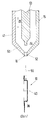
На фиг. 1 показаны расположенные в асептической камере опускающий механизм, поворотное устройство и упаковка на поднимающем ее кронштейне, на фиг. 2 разрез сопла клеевого устройства с разливочным устройством, расположенным под ним, с фланцем для нанесения клея; на фиг. 3 упаковка с отверстием наверху; на фиг. 4 разливочное устройство, вариант выполнения; на фиг. 5 разливочное устройство в разрезе. In FIG. 1 shows the lowering mechanism located in the aseptic chamber, the rotary device and the packaging on the lifting arm, FIG. 2 section of the nozzle of the adhesive device with a filling device located under it, with a flange for applying glue; in FIG. 3 packaging with a hole at the top; in FIG. 4 filling device, embodiment; in FIG. 5 sectional filling device.
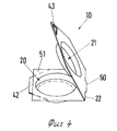
Разливочное устройство 10 состоит из дна 20 и крышки 21, которые соединены продольной петлей 22, причем крышка 21 может иметь запорный выступ 60 с задней стороны, показанному с захватной частью 43 в виде треугольного отверстия на выступе противоположной петле части (фиг. 4). Дно 20 и крышка 21 имеют чашеобразное углубление 36 и 39, которое образует фланец 38, когда все разливочное устройство 10 находится в закрытом состоянии, при этом фланец вставляется в воротничок 1 отверстия 13 в верхней части 9 упаковки 18, как показано на фиг. 5. Конкретная упаковка 18 (фиг. 3) в основном четырехугольная в сечении и образует продолговатую трубу с закругленными продольными ребрами 6-8, между которыми находятся практически плоские стенки 2, 3 и т.д. соединяющие верхнюю часть 9 с дном под ним (не показано). Усиливающее ребро 12 проходит также по выемке 11, которая выполнена на верхней грани 9 посредине, и через отверстие 13. Это усиливающее ребро одновременно образует влагонепроницаемое соединение между двумя половинками оболочки, из которых образована упаковка 18. Так как усиливающее ребро 12 присутствует также в районе отверстия 13, воротничок 1 отверстия 13 может иметь небольшие неровности или зазоры на диаметрально противоположных сторонах его внутренней поверхности, и эти зазоры должны быть закрыты при использовании разливочного устройства 10, как было описано выше. The filling
Специальный признак разливочного устройства 10 является неважным для описанного здесь способа и устройства, показанного на фиг. 1 и 2 для плотного закрывания упаковки 18. В частности, могут использоваться другие формы разливочных устройств для операции закрывания, если только они имеют фланец 38. Следует добавить, что дно 20 оборудовано разливочным отверстием 35, которое закрыто пластмассовой пленкой 51. Разливочный край 42 остается незакрытым. Запечатанное соединение между пластмассовой пленкой 51 и дном 20 выполнено только между двумя этими последними частями, тогда как крышка 21 вдавлена внутрь и может быть откинута вверх для открывания упаковки (фиг. 4 и 5) без нарушения герметичности, обеспечиваемой пластмассовой пленкой 51. Наконец, чтобы открыть упаковку нужно удалить пленку 51. A special feature of the filling
Асептическая камера 5, которая показана частичными линиями на фиг. 1, расположена внутри стенки 4, частично показанной на фиг. 1. В этой камере находятся главные части закрывающего устройства для упаковки 18. Снаружи стенки 4 находится клеевое устройство 14 с соплом 15, конец 16 которого с помощью кольцевого уплотнения (не показан) проходит через стенку 4 асептической камеры 5, так что она герметична, и внутри находится только конец 16 сопла 15, тогда как основная часть сопла 15 и в особенности клеевое устройство 14 расположены вне асептической камеры 5. Aseptic chamber 5, which is shown in partial lines in FIG. 1 is located inside the wall 4, partially shown in FIG. 1. In this chamber are the main parts of the closing device for
Внутри асептической камеры 5, показанной на фиг. 1, сверху вниз показаны опускающий механизм 19, конвейер 23, отрезное устройство 24, возможно соединенное с опускающим механизмом 19, поворотное устройство 25 и под ним упаковка 18, установленная на подъемном механизме 26 упаковок. Inside the aseptic chamber 5 shown in FIG. 1, a lowering mechanism 19, a conveyor 23, a cutting device 24, possibly connected to a lowering mechanism 19, a rotary device 25 and below it a
Опускающий механизм 19 и также стержень 27 в направляющей 28 может двигаться вертикально вверх и вниз в направлениях двойной стрелки 29, чтобы отделять каждое из разливочных устройств 10, которые подаются прерывисто конвейером 23 справа налево в направлении стрелки 30 влево в область под опускающий механизм 19, опускать их на вертикально стоящую первую оправку 31, которая направлена вверх, и отодвигать обратно вверх в направлении по стрелке 29. The lowering mechanism 19 and also the rod 27 in the guide 28 can move vertically up and down in the directions of the
Поворотное устройство 25 приводится в прерывистое вращение относительно горизонтальной главной оси 32, тогда как одновременно вторая оправка 33, диаметрально противоположная первой оправке 31 и направленная вниз (фиг. 1), может приводиться во вращение. Оправки 31 и 33 цилиндрической формы. Они могут поворачиваться относительно оси 32 каждый раз на 90о в направлении дуговой стрелки 37, например, из положения, показанного сплошными линиями, в горизонтальное положение, показанное пунктирными линиями на фиг. 1. Затем можно снова вращать оправку 31', которая направлена налево относительно ее продольной оси 40, точнее на 360о, или несколько раз по 360о, предпочтительно на угол, втрое превышающий 360о, после чего вращение относительно этой продольной оси 40 прерывается.The rotary device 25 is driven in intermittent rotation relative to the horizontal main axis 32, while at the same time the second mandrel 33, diametrically opposed to the first mandrel 31 and directed downward (Fig. 1), can be driven into rotation. Mandrels 31 and 33 are cylindrical in shape. They can be rotated about the axis 32 each time at 90 ° arc in the direction of arrow 37, for example, from the position shown in solid lines, to the horizontal position shown in dashed lines in FIG. 1. Then you can again rotate the mandrel 31 ', which is directed to the left relative to its
Направляющая 28 касается горизонтальной рамы машины 4', и стержень 27 может быть подан вверх и затем обратно вниз в направлении стрелки 29 на величину хода b, чтобы консольный конец оправки 31 или 33 вошел в оперативное взаимодействие с верхней частью 9 упаковки 18. The guide 28 touches the horizontal frame of the machine 4 ', and the rod 27 can be fed up and then back down in the direction of
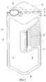
Сопло 15, показанное на фиг. 2, может иметь форму обычного впрыскивающего сопла, в котором, однако, условия работы изменены, так что вместо обычных для впрыскивающих сопел величин давления (порядка 60 бар) давление снижено до 5-7 бар, так что сопло 15 предпочтительно работает при питающем давлении 5 бар. The
Внешняя стенка 41 сопла, которая как цилиндрический кожух простирается вниз, сужаясь на конус 50, заканчивается выходным отверстием 52 цилиндрической формы внутри. The
Как и в обычных впрыскивающих соплах модифицированное сопло 15 по изобретению имеет цилиндрическую сопловую иглу 53 с наконечником 54, расположенную по оси сопла. Сопловая игла 53 также подвижна вверх и вниз по стрелке 29. На фиг. 2 она показана в верхнем положении, а когда игла подается вниз в крайнее положение, цилиндрический конец 54 иглы точно входит в выходное отверстие 52, за счет чего отверстие 52 полностью заполняется и закрывается. As in conventional injection nozzles, the modified
Если ось сопловой иглы 53 продолжить вниз, то двойная линия, показанная пунктиром, иллюстрирует клеевую нить 55. Следует понимать, что клеевая нить 55, показанная двойным пунктиром, показана не в масштабе, в особенности потому, что она полностью наматывается вокруг цилиндрической поверхности фланца 38 разливочного устройства 10, так что по меньшей мере одна линия нити 55 находится на поверхности фланца 38, когда разливочное устройство вращается, как было описано выше, предпочтительно трижды по 360о, но с тремя клеевыми нитями, расположенными рядом друг с другом или друг на друге. Это вращение производится вокруг продольной оси 40, показанной пунктиром, где оправка 31' мысленно находится слева (фиг. 2).If the axis of the
Чтобы клеевая нить 55, вытекающая из сопла 15 вниз, могла быть действительно вытянута, при вращении окружная скорость фланца 38 или поверхности оправки 31' больше скорости падения нити клея 55 из выходного отверстия 52, притом нить клея должна иметь определенную "жесткость", расстояние а между концом 16 сопла и верхней точкой фланца 38 разливочного устройства не должно превышать минимальной длины (в предпочтительном исполнении эта длина 25 см). Это применимо в исполнении, где температура горячего расплава приблизительно 170оС. Количество горячего расплава между моментом открывания выходного отверстия 52 до момента его закрывания примерно 0,18 г.So that the
Устройство для запечатывания упаковки с жидкостью работает следующим образом. A device for sealing a package of liquid works as follows.
Сопловая игла 53 перемещается из положения, показанного на фиг. 2, вниз, так что наконечник 54 полностью заполняет выходное отверстие 52 и закрывает его. Конвейер 23 подает цепочку соединенных вместе разливочных устройств 10 в направлении 30 таким образом, что разливочное устройство 10 выталкивается полностью влево под отрезное устройство 24 и находится над верхним торцом направленной вверх оправки 31. Опускающий механизм 19 движется затем в направлении стрелки 29 вертикально вниз, причем их одновременно приводимое в действие отрезное устройство 24 отделяет переднее разливочное устройство слева и немедленно после этого толкает его на первую оправку 31. Разливочное устройство 10 теперь насажено на первой оправке 31 таким образом, что она не скользит относительно нее (без больших усилий) и движется вместе в ней. Следующий рабочий ход будет через 4 с. The
Поворотное устройство 25 двигает первую оправку, поворачиваясь относительно горизонтальной главной оси против часовой стрелки в направлении дуговой стрелки 37 из положения I, где оправка обозначена позицией 31, в горизонтальное положение II влево, где оправка обозначена позицией 31'. Поворотное устройство 25 переместило две диаметрально противоположные оправки 31 и 33 в положение, показанное пунктиром, так что первая оправка 31' сейчас расположена в положении II горизонтально, так что ее продольная ось 40 также проходит горизонтально и перпендикулярно к главной оси 32. Оправка 31' начинает вращаться относительно продольной оси 40 на угол, который втрое превышает 360о. В начале вращательного движения наконечник сопловой иглы 54 вынимается из выходного отверстия сопла, когда иглу 53 подают вверх в направлении стрелки 29. Нить 55 клея затем вытекает и попадает на фланец 38 разливочного устройства 10 в одной точке. Горячий клей наносится оправкой 31' или фланцем 38, вращающимися вокруг продольной оси 40. Нить 55 клея таким образом вытекает из выходного отверстия 52 под действием и с помощью силы тяжести. В конкретном воплощении, рассматриваемом здесь, где зазор между концом сопла и фланцем по меньшей мере 25 мм, минимальная окружная скорость фланца 38 при его вращении на три оборота составляет 300 мм/с. Полоска клея 55 за этот счет растягивается и гарантированно укладывается на фланце 38 по прямой линии. Скорость истечения из сопла 15 поэтому меньше, чем окружная скорость оправки 31 в положении III или скорость фланца 38. Протяженность и расширение вытекающей нити 55 клея обеспечивает аккуратное линейное наложение. Вследствие трех оборотов, совершаемых прежде, чем нить 55 клея отсекается полным закрытием выходного отверстия 52, избегают стыков, начальных и конечных областей, которые не совпадают друг с другом. Вместо этого нанесение равномерное, без стыков. Когда нить 55 клея прерывается или когда она кончается цилиндрический конец 54 иглы полностью закрывает отверстие сопла 52 и таким образом прекращает подачу клея. Остаточная нить оттягивается от нити 55 клея, которая все еще идет на фланец и аккуратно наматывается вокруг него. Вращательное движение оправки 31' по отношению к движению сопловой иглы 53 точно засинхронизовано.The rotary device 25 moves the first mandrel, rotating counterclockwise relative to the horizontal main axis in the direction of the arc arrow 37 from position I, where the mandrel is indicated by position 31, to the horizontal position II to the left, where the mandrel is indicated by position 31 '. The rotary device 25 has moved two diametrically opposite mandrels 31 and 33 to the position shown by the dotted line, so that the first mandrel 31 'is now located in position II horizontally, so that its
В следующем прерывистом этапе поворотного устройства 25 оправка 31' поворачивается вниз в вертикальное положение на 90о, так что она занимает положение 33, показанное на фиг. 1 сплошной линией. Однако разливочное устройство все еще на ней насажено.In the next intermittent step of the rotary device 25, the mandrel 31 'is rotated downward into a vertical position by 90 ° , so that it occupies a position 33, shown in FIG. 1 solid line. However, the filling device is still mounted on it.
Стержень 27, направляемый в направляющей 28, теперь приходит в движение вместе с подъемным механизмом 26 упаковки, в направлении стрелки 29 вверх с ходом движения b, так что фланец 38 разливочного устройства вжимается в воротничок 1 отверстия 13 в упаковке 18. Стоячий воротничок 1 отверстия 13 контактирует с разливочным устройством 10 через слой клея или горячего расплава и приклеивается к разливочному устройству. Все щели или свободные места заполняются клеем, который вдавливается. The rod 27 guided in the guide 28 now moves together with the packaging lifting mechanism 26, in the direction of the
Так как сила прилипания клея еще недостаточна после нанесения горячего расплава снаружи разливочного устройства, при движении упаковки 18 вниз не показанная вспомогательная вилка помогает снять разливочное устройство 10 с оправки 33. Упаковка 18 затем влагонепроницаемо закрывается разливочным устройством 10. Since the adhesive strength of the glue is still insufficient after hot melt is applied outside the filling device, when the
Тогда как оправка 33 все еще в нижнем положении, обозначенном III, и освобождается заталкиванием во фланец отверстия 13, то сверху на противоположной стороне первая оправка 31, которая находится в противоположном положении I, снаряжается опускающим механизмом 19 следующим разливочным устройством, которое надевается и закрепляется на оправке. While the mandrel 33 is still in the lower position, designated III, and is released by pushing the
Поворотное устройство 25 затем поворачивает оправку 33 из положения III на 90о в положение IV, где оправка пустая и не выполняет никаких функций. Расположенная противоположно оправка 31' опять находится в положении II, где описанные уже процессы происходят вновь. Процедура повторяется, когда производится следующий шаг вращательного движения.The pivoting device 25 then rotates the mandrel 33 from position III 90 ° to position IV, where the mandrel is empty and does not perform any functions. Opposite mandrel 31 'is again in position II, where the processes already described are happening again. The procedure is repeated when the next step of the rotational movement is performed.
Claims (11)
Applications Claiming Priority (2)
| Application Number | Priority Date | Filing Date | Title |
|---|---|---|---|
| DEP4111758.1 | 1991-04-11 | ||
| DE4111758A DE4111758C2 (en) | 1991-04-11 | 1991-04-11 | Method and device for closing a package |
Publications (1)
| Publication Number | Publication Date |
|---|---|
| RU2044675C1 true RU2044675C1 (en) | 1995-09-27 |
Family
ID=6429318
Family Applications (1)
| Application Number | Title | Priority Date | Filing Date |
|---|---|---|---|
| SU925011376A RU2044675C1 (en) | 1991-04-11 | 1992-04-10 | Method of and device for sealing packs for liquids |
Country Status (24)
| Country | Link |
|---|---|
| US (1) | US5297375A (en) |
| EP (1) | EP0508222B1 (en) |
| JP (1) | JPH0672404A (en) |
| KR (1) | KR920019664A (en) |
| CN (1) | CN1030180C (en) |
| AR (1) | AR247175A1 (en) |
| AT (1) | ATE116613T1 (en) |
| AU (1) | AU654852B2 (en) |
| BR (1) | BR9201240A (en) |
| CA (1) | CA2065535A1 (en) |
| CS (1) | CS110192A3 (en) |
| DE (2) | DE4111758C2 (en) |
| DK (1) | DK0508222T3 (en) |
| ES (1) | ES2066505T3 (en) |
| FI (1) | FI921575A (en) |
| GR (1) | GR3015651T3 (en) |
| HU (1) | HU213238B (en) |
| MX (1) | MX9201612A (en) |
| NO (1) | NO921381L (en) |
| NZ (1) | NZ242297A (en) |
| RU (1) | RU2044675C1 (en) |
| SK (1) | SK110192A3 (en) |
| TW (1) | TW260648B (en) |
| ZA (1) | ZA922380B (en) |
Cited By (3)
| Publication number | Priority date | Publication date | Assignee | Title |
|---|---|---|---|---|
| US7228787B2 (en) | 2002-09-06 | 2007-06-12 | Dbt Gmbh | Method for joining the functional parts of hydraulic or pneumatic working devices, and joining connection |
| RU2573773C2 (en) * | 2010-06-30 | 2016-01-27 | Мэджик Продакшн Груп С.А. | Device and method for closing of containers |
| RU2675495C1 (en) * | 2015-10-05 | 2018-12-19 | Тетра Лаваль Холдингз Энд Файнэнс С.А. | Container pilfer-proof device |
Families Citing this family (11)
| Publication number | Priority date | Publication date | Assignee | Title |
|---|---|---|---|---|
| DE4228181A1 (en) * | 1992-08-25 | 1994-03-03 | Tetra Pak Gmbh | Device for attaching a pouring device to a package |
| DE4441097A1 (en) * | 1994-11-18 | 1996-05-23 | Ruediger Haaga Gmbh | Device for producing and attaching a protective cover when opening a wall for a container |
| CZ290890B6 (en) * | 1995-08-02 | 2002-11-13 | Sig Combibloc Gmbh & Co Kg | Method for machine application of pouring elements to flat-gabled packages and apparatus for making the same |
| US5851346A (en) * | 1997-05-29 | 1998-12-22 | Beckman Instruments, Inc. | Apparatus for sealing containers |
| CN1081156C (en) * | 1998-12-11 | 2002-03-20 | 孙慧德 | Lathe for cutting dismounting line of anti-counterfeit bottle and cutting method |
| US6205746B1 (en) * | 1999-01-28 | 2001-03-27 | Tetra Laval Holdings & Finance, Sa | Post-processing fitment applicator |
| DE102005030906A1 (en) * | 2005-06-30 | 2007-01-25 | Sm-Klebetechnik Vertriebs Gmbh | Head assembly for automatic high speed adhesive point application, neatly deposits adhesive thread pulled between nozzle and product |
| DE102007023400A1 (en) * | 2006-12-12 | 2008-06-19 | Robert Bosch Gmbh | Tactical machine for filling containers |
| ES2340541T3 (en) * | 2007-06-15 | 2010-06-04 | TETRA LAVAL HOLDINGS & FINANCE SA | SEPARATION UNIT TO SEPARATE OPENING DEVICES TO BE APPLIED INDIVIDUALLY TO RESPECTIVE CONTAINERS OF VERTIBLE FOOD PRODUCTS. |
| RU2578529C2 (en) * | 2012-01-20 | 2016-03-27 | О Энд Картон Лунд Аб | Device and method for attachment of covers to containers |
| CN109605027B (en) * | 2018-12-26 | 2021-05-07 | 广州精新泽自动化设备有限公司 | Submerged packaging mechanism of double-channel quick vibration damping seat assembly |
Family Cites Families (18)
| Publication number | Priority date | Publication date | Assignee | Title |
|---|---|---|---|---|
| US2296079A (en) * | 1939-01-23 | 1942-09-15 | Gen Mills Inc | Gluing head |
| US2419951A (en) * | 1945-03-03 | 1947-05-06 | Continental Can Co | Sealing compound applying apparatus |
| US2972184A (en) * | 1957-11-29 | 1961-02-21 | Andrew & Waitkens Machine Co I | Machine for mounting spouts in the tops of containers |
| US3029570A (en) * | 1958-05-29 | 1962-04-17 | Diamond National Corp | Packaging |
| US3054240A (en) * | 1960-10-18 | 1962-09-18 | Cons Packaging Machinery Corp | Capping equipment |
| GB1122199A (en) * | 1965-02-12 | 1968-07-31 | Wilhelm Beer | Improvements in or relating to the capping of containers |
| US3434908A (en) * | 1965-11-12 | 1969-03-25 | Summerhayes Holdings Ltd | Sealing head |
| CA963214A (en) * | 1970-11-18 | 1975-02-25 | Nordson Corporation | Method and apparatus for applying compound to can lids |
| GB1407601A (en) * | 1972-01-06 | 1975-09-24 | Metal Box Co Ltd | Container closures |
| US4274456A (en) * | 1979-12-06 | 1981-06-23 | Coors Container Company | Apparatus for dispensing fluid sealant |
| DE3263987D1 (en) * | 1981-03-02 | 1985-07-11 | Toyo Seikan Kaisha Ltd | Easily openable vessel closure and process for preparation thereof |
| US4592690A (en) * | 1982-10-08 | 1986-06-03 | Bonded Products, Inc. | Hot melt gasketing compositions and processes for applying them |
| SE439452B (en) * | 1983-12-15 | 1985-06-17 | Tetra Pak Int | SET TO SEAL AN EMPTY OPENING AND DEVICE IMPLEMENTATION DEVICE |
| DE3528815A1 (en) * | 1985-08-10 | 1987-02-12 | Berg Jacob Gmbh Co Kg | WELDED PLASTIC LOCK FOR PLASTIC CONTAINERS, METHOD FOR PRODUCING THE SAME AND DEVICE FOR IMPLEMENTING THE METHOD |
| SE452874B (en) * | 1986-04-17 | 1987-12-21 | Tetra Pak Ab | OPENING DEVICE BY A PACKAGING CONTAINER AND SET AND DEVICE FOR COMPLETING ITS |
| US4696143A (en) * | 1986-05-06 | 1987-09-29 | William P. Young Co. | Container capping apparatus |
| US4817363A (en) * | 1987-09-02 | 1989-04-04 | Owens-Illinois Plastic Products Inc. | Fitment inserter machine |
| US4990200A (en) * | 1989-12-29 | 1991-02-05 | Lever Brothers Company | Fitment application process and apparatus |
-
1991
- 1991-04-11 DE DE4111758A patent/DE4111758C2/en not_active Expired - Fee Related
-
1992
- 1992-03-26 EP EP92105171A patent/EP0508222B1/en not_active Expired - Lifetime
- 1992-03-26 ES ES92105171T patent/ES2066505T3/en not_active Expired - Lifetime
- 1992-03-26 DE DE59201113T patent/DE59201113D1/en not_active Expired - Fee Related
- 1992-03-26 AT AT92105171T patent/ATE116613T1/en not_active IP Right Cessation
- 1992-03-26 DK DK92105171.0T patent/DK0508222T3/en active
- 1992-04-01 ZA ZA922380A patent/ZA922380B/en unknown
- 1992-04-07 BR BR929201240A patent/BR9201240A/en not_active Application Discontinuation
- 1992-04-07 US US07/864,549 patent/US5297375A/en not_active Expired - Fee Related
- 1992-04-07 CA CA002065535A patent/CA2065535A1/en not_active Abandoned
- 1992-04-08 AU AU14784/92A patent/AU654852B2/en not_active Ceased
- 1992-04-08 NO NO92921381A patent/NO921381L/en unknown
- 1992-04-08 MX MX9201612A patent/MX9201612A/en not_active IP Right Cessation
- 1992-04-08 HU HU9201181A patent/HU213238B/en not_active IP Right Cessation
- 1992-04-09 FI FI921575A patent/FI921575A/en not_active Application Discontinuation
- 1992-04-09 AR AR92322105A patent/AR247175A1/en active
- 1992-04-09 NZ NZ242297A patent/NZ242297A/en unknown
- 1992-04-10 JP JP4090583A patent/JPH0672404A/en not_active Withdrawn
- 1992-04-10 SK SK1101-92A patent/SK110192A3/en unknown
- 1992-04-10 CS CS921101A patent/CS110192A3/en unknown
- 1992-04-10 RU SU925011376A patent/RU2044675C1/en active
- 1992-04-11 CN CN92102689A patent/CN1030180C/en not_active Expired - Fee Related
- 1992-04-11 KR KR1019920006057A patent/KR920019664A/en active IP Right Grant
- 1992-04-28 TW TW081103386A patent/TW260648B/zh active
-
1995
- 1995-04-03 GR GR950400795T patent/GR3015651T3/en unknown
Non-Patent Citations (1)
| Title |
|---|
| Прототип известен заявителю. * |
Cited By (5)
| Publication number | Priority date | Publication date | Assignee | Title |
|---|---|---|---|---|
| US7228787B2 (en) | 2002-09-06 | 2007-06-12 | Dbt Gmbh | Method for joining the functional parts of hydraulic or pneumatic working devices, and joining connection |
| RU2573773C2 (en) * | 2010-06-30 | 2016-01-27 | Мэджик Продакшн Груп С.А. | Device and method for closing of containers |
| MD4528B1 (en) * | 2010-06-30 | 2017-11-30 | Magic Production Group S.A. | Device and method for closing containers |
| RU2675495C1 (en) * | 2015-10-05 | 2018-12-19 | Тетра Лаваль Холдингз Энд Файнэнс С.А. | Container pilfer-proof device |
| US10815017B2 (en) | 2015-10-05 | 2020-10-27 | Tetra Laval Holdings & Finance S.A. | Apparatus for capping a container |
Also Published As
| Publication number | Publication date |
|---|---|
| US5297375A (en) | 1994-03-29 |
| HU9201181D0 (en) | 1992-07-28 |
| CN1067628A (en) | 1993-01-06 |
| DE4111758A1 (en) | 1992-10-15 |
| KR920019664A (en) | 1992-11-19 |
| DE59201113D1 (en) | 1995-02-16 |
| ATE116613T1 (en) | 1995-01-15 |
| EP0508222A1 (en) | 1992-10-14 |
| NZ242297A (en) | 1993-09-27 |
| GR3015651T3 (en) | 1995-07-31 |
| FI921575A (en) | 1992-10-12 |
| AU654852B2 (en) | 1994-11-24 |
| MX9201612A (en) | 1994-05-31 |
| SK110192A3 (en) | 1994-12-07 |
| TW260648B (en) | 1995-10-21 |
| EP0508222B1 (en) | 1995-01-04 |
| HUT64278A (en) | 1993-12-28 |
| DK0508222T3 (en) | 1995-06-06 |
| CS110192A3 (en) | 1992-10-14 |
| AR247175A1 (en) | 1994-11-30 |
| NO921381D0 (en) | 1992-04-08 |
| HU213238B (en) | 1997-03-28 |
| ZA922380B (en) | 1992-12-30 |
| JPH0672404A (en) | 1994-03-15 |
| DE4111758C2 (en) | 1996-10-17 |
| CN1030180C (en) | 1995-11-01 |
| NO921381L (en) | 1992-10-12 |
| CA2065535A1 (en) | 1992-10-12 |
| BR9201240A (en) | 1992-12-01 |
| ES2066505T3 (en) | 1995-03-01 |
| AU1478492A (en) | 1992-10-15 |
| FI921575A0 (en) | 1992-04-09 |
Similar Documents
| Publication | Publication Date | Title |
|---|---|---|
| RU2044675C1 (en) | Method of and device for sealing packs for liquids | |
| US6958033B1 (en) | Thin wall fitment for spouted pouch | |
| DE69634302T2 (en) | METHOD FOR FIXING OBJECTS TO A CARTON SURFACE | |
| KR101015747B1 (en) | Self-opening closure for composite packagings or for container or bottle nozzles for sealing with film material | |
| US3314210A (en) | Process and a device for manufacturing packages | |
| JPH0323436B2 (en) | ||
| CA2014557A1 (en) | Apparatus and methods for dispensing foamable products | |
| JPS629019B2 (en) | ||
| KR100441873B1 (en) | Teabag Making Equipment and Manufacturing Method and Tea Bag | |
| AU7519094A (en) | Aseptic brick package | |
| RU2246403C2 (en) | Device for manufacturing double-chamber containers | |
| US4666064A (en) | Dispensing device for "bag-in-box" packages, bag and device for filling bags | |
| US20130230613A1 (en) | Apparatuses and methods for obtaining an object such as a seal, and a seal for containers | |
| US4074961A (en) | Apparatus for producing containers | |
| CA2142321A1 (en) | A pack for adhesives and/or sealants | |
| JP2011528288A5 (en) | ||
| US5149065A (en) | Foam cushion with labyrinthine side seams | |
| US4646507A (en) | Machine for making packs for flowing material | |
| AU2002225690A1 (en) | Method of making dual chamber sachet | |
| US3454208A (en) | Two-piece plastic container | |
| US3507422A (en) | Flexible dispensing nozzle for use in an automatic bag filling machine | |
| EP0661221A1 (en) | Liner packaging for reactive hot melt adhesive | |
| US5340421A (en) | Method using a cam for folding a seal removal tab on a collapsible tube | |
| JPS6113980B2 (en) | ||
| CA2158900C (en) | Machine and method for making a plastic film pouch and attaching a spout thereto |