RU106972U1 - DISTRIBUTED NETWORK MANAGEMENT SYSTEM - Google Patents
DISTRIBUTED NETWORK MANAGEMENT SYSTEM Download PDFInfo
- Publication number
- RU106972U1 RU106972U1 RU2011113432/08U RU2011113432U RU106972U1 RU 106972 U1 RU106972 U1 RU 106972U1 RU 2011113432/08 U RU2011113432/08 U RU 2011113432/08U RU 2011113432 U RU2011113432 U RU 2011113432U RU 106972 U1 RU106972 U1 RU 106972U1
- Authority
- RU
- Russia
- Prior art keywords
- network node
- redundant
- main
- controllers
- unit
- Prior art date
Links
Landscapes
- Safety Devices In Control Systems (AREA)
Abstract
Распределенная сетевая система управления, содержащая как минимум один основной сетевой узел, имеющий возможность связи с датчиками параметров и исполнительными механизмами агрегата объекта, а также связанные с сетевым узлом основной и дублирующий коммутационные контроллеры, причем сетевой узел и коммутационные контроллеры имеют возможность соединения с источником питания, отличающаяся тем, что система оснащена как минимум одним резервным сетевым узлом, имеющим возможность связи с датчиками параметров и исполнительными механизмами агрегата объекта, а также связанными с резервным узлом основным и дублирующим коммутационным контроллерами, связанными основной и дублирующей шинами соответственно с основным и дублирующим контроллерами основного сетевого узла, резервный сетевой узел и его коммутационные контроллеры имеют возможность соединения с источником питания, при этом основной сетевой узел и его коммутационные контроллеры имеют возможность соединения с источником питания через нормально замкнутый ключ, а резервный сетевой узел и его коммутационные контроллеры - через нормально разомкнутый ключ, основной сетевой узел имеет возможность соединения с исполнительными механизмами через нормально замкнутый ключ, а резервный сетевой узел - через нормально разомкнутый ключ, при этом система дополнительно оснащена блоком обнаружения электромагнитного излучения и блоком логики, первый вход которого соединен с блоком обнаружения электромагнитного излучения, второй вход - с управляющим выходом резервного сетевого узла, а выходы блока логики связаны с ключами. A distributed network control system containing at least one main network node that can communicate with parameter sensors and actuators of the unit assembly, as well as main and redundant switching controllers connected to the network node, and the network node and switching controllers have the ability to connect to a power source, characterized in that the system is equipped with at least one redundant network node having the ability to communicate with parameter sensors and actuators the unit of the facility, as well as the main and redundant switching controllers connected to the redundant node, the main and redundant buses connected to the primary and redundant controllers of the main network node, the redundant network node and its switching controllers have the ability to connect to a power source, while the main network node and its switching controllers have the ability to connect to a power source through a normally closed key, and the backup network node and its switching controllers ery - through a normally open key, the main network node can connect to actuators through a normally closed key, and the backup network node can be connected through a normally open key, while the system is additionally equipped with an electromagnetic radiation detection unit and a logic unit, the first input of which is connected to the unit detection of electromagnetic radiation, the second input - with the control output of the backup network node, and the outputs of the logic unit are connected with the keys.
Description
Полезная модель относится к области распределенных сетевых систем управления и может быть использована для обеспечения синхронизации работы агрегатов объекта с обеспечением защиты узлов системы от действия электромагнитного излучения (ЭМИ) различного происхождения.The utility model relates to the field of distributed network control systems and can be used to ensure synchronization of the operation of the units of the facility with the protection of the nodes of the system from electromagnetic radiation (EMR) of various origins.
Задачи синхронизации по управлению и по данным узлов сетевых распределенных систем возникают при эксплуатации объектов автотранспорта, авиации, энергетики, например в системах автоматического управления газотурбинными двигателями, в системах рулевого управления автомобиля и при эксплуатации других объектов, при функционировании которых недопустимо, чтобы их исполнительные устройства получали не скоординированные, не синхронизированные между собой команды управления.Synchronization tasks for control and according to the nodes of networked distributed systems arise during the operation of motor vehicles, aviation, energy, for example, in automatic control systems for gas turbine engines, in the steering systems of a car and during the operation of other objects, the functioning of which is unacceptable for their actuators to receive not coordinated, not synchronized control teams.
В настоящее время стала актуальной проблема обеспечения стойкости таких систем управления к воздействию ЭМИ искусственного и естественного происхождения. В природе источником ЭМИ являются импульсные токи, сопровождающие нестационарные природные явления - магнитные бури, удары молнии, электростатические разряды. В технике источниками ЭМИ являются электромагнитные поля радиопередающих и радиолокационных станций (РЛС), высоковольтные линии электропередач, импульсные электротехнические устройства, в том числе, электромагнитное оружие. Источником наиболее мощного ЭМИ является ядерный взрыв.Currently, the problem of ensuring the resistance of such control systems to the effects of EMR of artificial and natural origin has become urgent. In nature, the source of electromagnetic radiation is pulsed currents accompanying unsteady natural phenomena - magnetic storms, lightning strikes, electrostatic discharges. In technology, the sources of electromagnetic radiation are electromagnetic fields of radio transmitting and radar stations (radar), high-voltage power lines, pulsed electrical devices, including electromagnetic weapons. The source of the most powerful EMP is a nuclear explosion.
Известна система электропитания РЛС, состоящая из ввода внешней сети, блока защиты от перенапряжений первичной цепи, защитно-распределительного блока, обеспечивающего защиту цепей от токов короткого замыкания, устройства защиты от электромагнитного оружия с блоком индикации и с индивидуальными широкополосными фильтрами для каждой из нагрузок, первых преобразователей, питающих передающее устройство, второго преобразователя, питающего приводы РЛС, третьего преобразователя, подключенного к аккумулятору, питающему электронно-вычислительную машину РЛС, последовательно включенных четвертых и пятых прямоходовых преобразователей, питающих аппаратуру РЛС, шестых и седьмых резонансных преобразователей, питающих приемное устройство, и восьмых резонансных преобразователей, питающих формирователь эталонных сигналов, входы первых, второго, третьего, четвертых прямоходовых и шестых резонансных преобразователей подключены к выходам устройства защиты от электромагнитного оружия, входы пятых прямоходовых преобразователей подключены к выходам четвертых, а входы седьмых и восьмых резонансных преобразователей - к выходам шестых резонансных преобразователей, цепь управления соединяет защитно-распределительный блок и устройство защиты от электромагнитного оружия.A known radar power supply system, consisting of inputting an external network, a primary circuit surge protection unit, a protective distribution block providing circuit protection against short circuit currents, an electromagnetic weapon protection device with an indication unit and with individual broadband filters for each of the loads, the first converters feeding the transmitting device, the second converter feeding the radar drives, the third converter connected to the battery, feeding electronically a radar machine, the fourth and fifth linear converters in series, feeding the radar equipment, the sixth and seventh resonant converters feeding the receiving device, and the eighth resonant converters feeding the reference signal generator, the inputs of the first, second, third, fourth linear and sixth resonant converters are connected to the outputs of the device for protection against electromagnetic weapons, the inputs of the fifth linear converters are connected to the outputs of the fourth, and the inputs of the seventh and the seventh resonant transducers - to the outputs of the sixth resonant transducers, the control circuit connects the protective distribution block and the protection device against electromagnetic weapons.
Для электропитания системы может быть использована подстанция, имеющая на выходе трехфазное напряжение 380 В, 50 Гц, которое подается через блок защиты от перенапряжений первичной сети на вход защитно-распределительного блока или резервный источник питания (аккумулятор). В систему электропитания включен помехоподавляющий фильтр для защиты системы от электромагнитных импульсов микросекундной длительности.To power the system, a substation can be used that has a three-phase voltage of 380 V, 50 Hz at the output, which is supplied through the primary network surge protection block to the input of the protective distribution block or a backup power source (battery). An noise suppression filter is included in the power supply system to protect the system from electromagnetic pulses of microsecond duration.
При возникновении в первичной сети импульсов наносекундной длительности, вызванных применением электромагнитного оружия, узел индикации устройства защиты от электромагнитного оружия информирует обслуживающий персонал о наличии и уровне этих импульсов, что позволяет при необходимости перевести работу системы на резервный источник питания.When nanosecond pulses occur in the primary network caused by the use of electromagnetic weapons, the display unit of the electromagnetic weapons protection device informs maintenance personnel about the presence and level of these pulses, which allows, if necessary, to transfer the system to a backup power source.
(см. патент РФ №2399138, кл. Н02J 1/06, 2010 г.).(see RF patent No. 2399138, CL H2J 1/06, 2010).
В результате анализа выполнения известной системы необходимо отметить, что она обеспечивает защиту от ЭМИ искусственного и естественного происхождения, однако она весьма сложна конструктивно, использование в качестве защитных элементов широкополосных фильтров снижает эффективность защиты, так как обеспечивает защиту только от ЭМИ имеющих параметры, укладывающиеся в полосу пропускания фильтров. Данная система не является эффективной от защиты импульсов наносекундной длительности вследствие ее инерционности. Кроме того, при обнаружении ЭМИ осуществляется отключение всех механизмов РЛС, питание которых с целью сохранения в них информации осуществляется в течение определенного времени от аккумулятора. Кроме того, выполнение системы не обеспечивает диагностирования состояния ее узлов и агрегатов после окончания действия ЭМИ.As a result of the analysis of the implementation of the known system, it should be noted that it provides protection against EMP of artificial and natural origin, however, it is very structurally complex, the use of broadband filters as protective elements reduces the protection efficiency, since it provides protection only against EMP having parameters that fit into the strip passing filters. This system is not effective from protecting pulses of nanosecond duration due to its inertia. In addition, when EMR is detected, all mechanisms of the radar are switched off, the power of which in order to store information in them is carried out for a certain time from the battery. In addition, the implementation of the system does not provide a diagnosis of the state of its components and assemblies after the end of the EMR.
Известно устройство питания нагрузки, содержащее преобразователь переменного тока в постоянный, аккумуляторные батареи, коммутационные аппараты и блок управления. Блок управления осуществляет контроль состояния аккумуляторных батарей и управляет коммутационными аппаратами. Каждая отдельно взятая аккумуляторная батарея подключена в точке между двух последовательно соединенных коммутационных аппаратов и образует с каждым из них последовательное соединение либо с входной цепью питания нагрузки, либо с выходной цепью преобразователя.It is known a load power device comprising an AC to DC converter, rechargeable batteries, switching devices and a control unit. The control unit monitors the condition of the batteries and controls the switching devices. Each individual battery is connected at a point between two series-connected switching devices and forms a series connection with each of them either with the input load power circuit or with the converter output circuit.
В процессе работы устройства коммутационные аппараты, соединяющие аккумуляторные батареи с выходом преобразователя и входом питания нагрузки, включаются и отключаются так, что исключается прямое соединение выхода преобразователя с входом питания нагрузки. Аккумуляторная батарея подключается либо только к выходу преобразователя, либо только к входу питания нагрузки. Для того чтобы при отключении одной аккумуляторной батареи от входа нагрузки питание нагрузки не прерывалось, вторая аккумуляторная батарея перед отключением первой также подключается своим коммутационным аппаратом к входу питания нагрузки и отключается от выхода преобразователя. Затем циклы коммутации обеих аккумуляторных батарей повторяются. Управление коммутационными аппаратами осуществляет блок управления. Одновременно блок управления осуществляет контроль состояния аккумуляторных батарей и определяет оптимальные условия их подзаряда, регулируя длительность и ток заряда для каждой аккумуляторной батареи при их подключении к преобразователю. Таким образом, питание нагрузки всегда осуществляется от аккумуляторных батарей без непосредственной связи с выходом преобразователя и это обеспечивает защиту от ЭМИ. Кроме того, аккумуляторные батареи постоянно подзаряжаются, что обеспечивает длительную работу нагрузки.In the process of the device’s operation, switching devices connecting the batteries with the converter output and the load power input are turned on and off so that the direct connection of the converter output to the load power input is excluded. The battery is connected either to the inverter output only or to the load power input only. In order to ensure that the load supply is not interrupted when one battery is disconnected from the load input, the second battery before disconnecting the first is also connected by its switching device to the load power input and disconnected from the converter output. Then, the switching cycles of both batteries are repeated. Switching devices are controlled by a control unit. At the same time, the control unit monitors the state of the batteries and determines the optimal conditions for their recharging, adjusting the duration and charge current for each battery when they are connected to the converter. Thus, the load is always supplied from rechargeable batteries without direct connection with the converter output and this provides protection against EMP. In addition, the batteries are constantly recharged, which ensures long-term operation of the load.
(см. патент РФ №2396662, кл. Н02J 1/02, 2010 г.).(see RF patent No. 2396662, CL H2J 1/02, 2010).
В результате анализа выполнения данного устройства необходимо отметить, что оно не обеспечивает надежной защиты от ЭМИ, так как для него характерно низкое быстродействие узлов отключения нагрузки, в то время, как длительность ЭМИ может составлять несколько микросекунд, а наличие в устройстве аккумуляторных батарей, значительно увеличивает вес и габариты системы, особенно при управлении объектами с большим количеством работающих в едином цикле агрегатов, что существенно ограничивает область ее применения.As a result of the analysis of the implementation of this device, it should be noted that it does not provide reliable protection against EMR, since it is characterized by low speed of load disconnecting nodes, while the duration of the EMR can be several microseconds, and the presence of rechargeable batteries in the device significantly increases weight and dimensions of the system, especially when managing facilities with a large number of units operating in a single cycle, which significantly limits the scope of its application.
Известна распределенная сетевая система управления, состоящая из сетевых узлов, каждый из которых имеет возможность связи со своей группой датчиков и своей группой исполнительных механизмов, все сетевые узлы связаны в единую систему через контроллеры основной системной шиной. Система оснащена дополнительными контроллерами, контроллерами основной и дублирующей коммуникационных шин, основным и дублирующим блоками памяти контрольных точек, дополнительные коммуникационные контроллеры связаны друг с другом дублирующей системной шиной и каждый из них связан с одним из сетевых узлов. Контроллеры основной и дублирующей коммуникационных шин связаны соответственно с основной и дублирующей системными шинами и через них с контроллерами, обеспечивающими синхронизацию работы сетевых узлов. Контроллеры основной и дублирующей коммуникационных шин также связаны друг с другом синхронизирующей шиной, при этом контроллер основной коммуникационной шины связан с основным блоком памяти контрольных точек, а контроллер дублирующей коммуникационной шины - с дублирующим блоком памяти контрольных точек.A distributed network control system is known, consisting of network nodes, each of which has the ability to communicate with its own group of sensors and its own group of actuators, all network nodes are connected into a single system through controllers by the main system bus. The system is equipped with additional controllers, controllers of the main and backup communication buses, primary and backup memory blocks of control points, additional communication controllers are connected to each other by a backup system bus and each of them is connected to one of the network nodes. The controllers of the main and redundant communication buses are connected respectively with the main and redundant system buses and through them with controllers that provide synchronization of the operation of network nodes. The controllers of the main and duplicate communication buses are also connected to each other by a synchronization bus, while the controller of the main communication bus is connected to the main memory block of control points, and the controller of the duplicate communication bus to the duplicate memory block of control points.
В процессе работы системы сетевые узлы считывают информацию со своих групп датчиков и выдают управляющие воздействия на свои группы исполнительных механизмов, а также посредством контроллеров обмениваются сообщениями по основной и дублирующей шинам данных в соответствии с жестким временным расписанием. При возникновении отказа в одном или нескольких узлах сети (например, вследствие воздействия электромагнитного импульса или сбоя по питанию), отказавшие узлы выполняют операцию перезагрузки, после чего получают от работающих узлов сети разрешение на вхождение в сеть.During the operation of the system, network nodes read information from their groups of sensors and issue control actions to their groups of actuators, as well as through controllers exchange messages on the main and duplicate data buses in accordance with a strict time schedule. If a failure occurs in one or more network nodes (for example, due to an electromagnetic pulse or a power failure), the failed nodes perform a reboot operation, after which they receive permission to enter the network from working network nodes.
(см. патент РФ на полезную модель №102339, кл. G05F 1/12, 2011 г.) - наиболее близкий аналог.(see RF patent for utility model No. 102339, class G05F 1/12, 2011) is the closest analogue.
В результате анализа данной системы необходимо отметить, что ее недостатком является то, что механизм перезагрузки узлов позволяет восстановить работу системы лишь в случае сохранения узлами их физической работоспособности. Однако, при физическом отказе узлов под воздействием мощного ЭМИ система выходит из строя и не имеет возможности восстановления.As a result of the analysis of this system, it should be noted that its drawback is that the mechanism for reloading nodes allows you to restore the system only if the nodes maintain their physical performance. However, with a physical failure of the nodes under the influence of a powerful EMR system fails and does not have the ability to recover.
Техническим результатом настоящей полезной модели является повышение надежности функционирования распределенной сетевой системы управления в условиях воздействия ЭМИ.The technical result of this utility model is to increase the reliability of the functioning of a distributed network control system under the influence of electromagnetic radiation.
Указанный технический результат обеспечивается тем, что в распределенной сетевой системе управления, содержащей как минимум, один основной сетевой узел, имеющий возможность связи с датчиками параметров и исполнительными механизмами агрегата объекта, а также связанные с сетевым узлом основной и дублирующий коммутационные контроллеры, причем сетевой узел и коммутационные контроллеры имеют возможность соединения с источником питания, новым является то, что система оснащена как минимум, одним резервным сетевым узлом, имеющим возможность связи с датчиками параметров и исполнительными механизмами агрегата объекта, а также связанными с резервным узлом основным и дублирующим коммутационным контроллерами, связанными основной и дублирующей шинами соответственно с основным и дублирующим контроллерами основного сетевого узла, резервный сетевой узел и его коммуникационные контроллеры имеют возможность соединения с источником питания, при этом, основной сетевой узел и его коммутационные контроллеры имеют возможность соединения с источником питания через нормально замкнутый ключ, а резервный сетевой узел и его коммутационные контроллеры - через нормально разомкнутый ключ, основной сетевой узел имеет возможность соединения с исполнительными механизмами через нормально замкнутый ключ, а резервный сетевой узел - через нормально разомкнутый ключ, при этом система дополнительно оснащена блоком обнаружения электромагнитного излучения и блоком логики, первый вход которого соединен с блоком обнаружения электромагнитного излучения, второй вход - с управляющим выходом резервного сетевого узла, а выходы блока логики связаны с ключами.The specified technical result is ensured by the fact that in a distributed network control system containing at least one main network node having the ability to communicate with parameter sensors and actuators of the unit assembly, as well as main and duplicate switching controllers connected to the network node, the network node and switching controllers have the ability to connect to a power source, the new one is that the system is equipped with at least one redundant network node that has the ability communication with the parameter sensors and actuators of the unit of the facility, as well as the primary and redundant switching controllers connected to the redundant node, the primary and redundant buses connected to the primary and redundant controllers of the main network node, the redundant network node and its communication controllers can connect to a power source at the same time, the main network node and its switching controllers have the ability to connect to a power source through normally close key, and the backup network node and its switching controllers through a normally open key, the main network node can connect to actuators via a normally closed key, and the backup network node through a normally open key, and the system is additionally equipped with an electromagnetic radiation detection unit and a logic unit, the first input of which is connected to the electromagnetic radiation detection unit, the second input - with the control output of the backup network node, and the outputs of the block l geeks are associated with the keys.
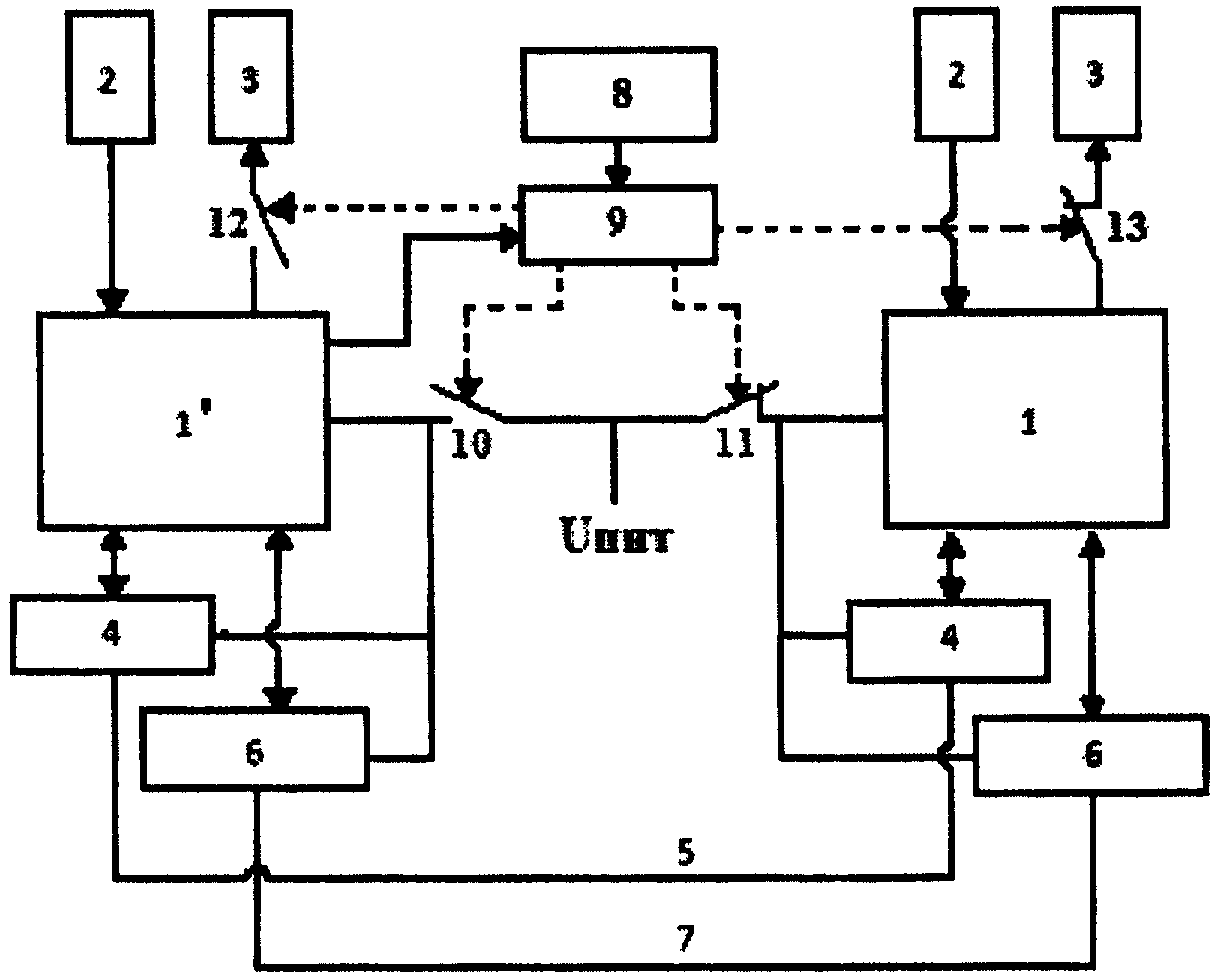
Сущность полезной модели поясняется графическими материалами, на которых представлена схема распределенной сетевой системы управления. На схеме представлена система, имеющая один основной и один резервный узлы, что не означает, что их количество не может быть иным.The essence of the utility model is illustrated by graphic materials on which a diagram of a distributed network management system is presented. The diagram shows a system having one primary and one backup nodes, which does not mean that their number cannot be different.
Распределенная сетевая система управления состоит из одного или нескольких основных сетевых узлов 1 и одного или нескольких резервных сетевых узлов 1'. Количество основных и резервных сетевых узлов системы, как правило, одинаково и соответствует количеству агрегатов объекта, работа которых должна осуществляться в жестко завязанном временном цикле.A distributed network management system consists of one or more main network nodes 1 and one or more redundant network nodes 1 '. The number of primary and backup network nodes of the system, as a rule, is the same and corresponds to the number of units of the object, the work of which should be carried out in a rigidly tied time cycle.
Основной сетевой узел (каждый основной сетевой узел) 1 связан со своей группой датчиков 2 (отслеживающих параметры одного из агрегатов объекта) и своей группой исполнительных механизмов 3 агрегата (управляемых данным основным сетевым узлом).The main network node (each main network node) 1 is connected to its group of sensors 2 (monitoring the parameters of one of the units of the object) and its group of actuators 3 of the unit (controlled by this main network node).
Резервный сетевой узел (каждый резервный сетевой узел) 1' также связан со своей группой датчиков 2, (отслеживающих параметры одного из агрегатов объекта) и своей группой исполнительных механизмов 3 агрегата (управляемых данным резервным сетевым узлом при неработающем основном сетевом узле).The redundant network node (each redundant network node) 1 'is also associated with its group of sensors 2, (monitoring the parameters of one of the units of the object) and its group of actuators 3 of the unit (controlled by this redundant network node with the main network node idle).
Все сетевые узлы (1 и 1') связаны в единую систему через коммутационные контроллеры 4 основной системной шиной 5 и через коммутационные контроллеры 6 дублирующей системной шиной 7.All network nodes (1 and 1 ') are connected into a single system through switching controllers 4 by the main system bus 5 and through switching controllers 6 by a redundant system bus 7.
Таким образом, каждый агрегат объекта имеет возможность управления как основным сетевым узлом 1, так и резервным 1'.Thus, each unit of the object has the ability to control both the main network node 1 and the backup 1 '.
Распределенная сетевая система оснащена блоком 8 обнаружения ЭМИ, связанным с первым входом блока логики 9, который управляет состоянием ключей 10, 11, 12 и 13. Второй вход блока логики 9 связан с управляющими выходами резервного сетевого узла (узлов) 1'. Ключи 11 и 13 являются нормально замкнутыми, а ключи 10 и 12 - нормально разомкнутыми.The distributed network system is equipped with an EMR detecting unit 8 connected to the first input of the logic unit 9, which controls the state of the keys 10, 11, 12, and 13. The second input of the logic unit 9 is connected to the control outputs of the backup network node (s) 1 '. Keys 11 and 13 are normally closed, and keys 10 and 12 are normally open.
Основной сетевой узел (узлы) 1 и связанные с ним (ними) коммутационные контроллеры 4 и 6 имеют возможность подключения к источнику питания (Uпит - не показан на схеме) через нормально замкнутый ключ (ключи) 11, а резервный сетевой узел (узлы) 1' и связанные с ним (ними) коммутационные контроллеры 4 и 6 имеют (имеют) возможность подключения к источнику питания (Uпит) через нормально разомкнутый ключ (ключи) 10.The main network node (nodes) 1 and the associated controllers 4 and 6 have the ability to connect to a power source (U pit - not shown in the diagram) through a normally closed key (s) 11, and a backup network node (nodes) 1 'and the associated controllers 4 and 6 have (have) the ability to connect to a power source (U pit ) through a normally open key (s) 10.
Основной сетевой узел 1 (каждый основной сетевой узел 1) связан со своей группой исполнительных механизмов 3 через нормально замкнутый ключ (ключи) 13.The main network node 1 (each main network node 1) is connected to its group of actuators 3 through a normally closed key (s) 13.
Резервный сетевой узел 1' (каждый резервный сетевой узел 1') связан со своей группой исполнительных механизмов 3 через нормально разомкнутый ключ (ключи) 12.The redundant network node 1 '(each redundant network node 1') is connected to its group of actuators 3 through a normally open key (s) 12.
Количество основных и резервных сетевых узлов может быть различным и зависит от количества управляемых работающих в режиме единого цикла агрегатов объекта.The number of primary and backup network nodes can be different and depends on the number of managed units operating in a single cycle mode.
Конструктивно система реализована на базе известных средств. В качестве основных и резервных сетевых узлов (их выполнение, как правило, одинаково) могут быть использованы узлы, аналогичные по конструкции, представленной в описании полезной модели РФ №95205. В качестве контроллеров шин могут быть использованы микроконтроллеры 1986ВЕ91 фирмы Миландр (г.Зеленоград). Блок 8 обнаружения ЭМИ может быть выполнен на оптопаре диодной 3ОД101Б, блок логики 9 может быть выполнен на транзисторах 2Т630Б и реле РЭС52.Structurally, the system is implemented on the basis of well-known tools. As the main and backup network nodes (their implementation, as a rule, is the same), nodes can be used that are similar in design presented in the description of the utility model of the Russian Federation No. 95205. As bus controllers, microcontrollers 1986ВЭ91 of the company Milander (Zelenograd) can be used. Block 8 EMR detection can be performed on the optocoupler diode 3OD101B, logic block 9 can be performed on transistors 2T630B and relay RES52.
Распределенная сетевая система управления работает следующим образом.Distributed network management system operates as follows.
В процессе нормального функционирования системы и управляемого ей объекта нормально замкнутые ключи 11 обеспечивают подачу питания (Uпит) к основным сетевым узлам 1 и коммутационным контроллерам 4 и 6, а нормально замкнутые ключи 13 обеспечивают подключение исполнительных механизмов 3 к основным сетевым узлам 1. При этом контроллеры 4 и 6 обеспечивают информационный обмен между основными сетевыми узлами, а контроллеры резервных узлов находятся в обесточенном состоянии.During the normal functioning of the system and the object managed by it, normally closed keys 11 provide power (U pit ) to the main network nodes 1 and switching controllers 4 and 6, and normally closed keys 13 provide the connection of actuators 3 to the main network nodes 1. At the same time controllers 4 and 6 provide information exchange between the main network nodes, and the backup node controllers are in a de-energized state.
При обнаружении ЭМИ блок 8 формирует управляющий сигнал, который поступает на первый вход блока логики 9, последний сначала выдает сигнал на размыкание ключей 11 и 13, что обеспечивает обесточивание коммутационных контроллеров 4 и 6 основного узла и основных сетевых узлов 1 и отключение их от управления исполнительными механизмами 3, а затем с заданной задержкой, обеспечивающей завершение действия ЭМИ, выдает сигнал на замыкание ключей 10 и 12, что обеспечивает включение в работу резервных сетевых узлов 1' и связанных с ними коммутационных контроллеров 4 и 6. Длительность задержки определяется выбором номинальных значений элементов схемы и составляет 100-200 миллисекунд. При этом основные и резервные сетевые узлы находятся в обесточенном состоянии, а исполнительные механизмы остаются в положениях, предшествующих моменту обнаружения ЭМИ. После завершения действия задержки управление агрегатами объекта осуществляется резервным сетевым узлом (узлами).When EMR is detected, block 8 generates a control signal that is fed to the first input of logic block 9, the latter first gives a signal to open the keys 11 and 13, which ensures that the switching controllers 4 and 6 of the main node and the main network nodes 1 are disconnected and they are disconnected from the executive control mechanisms 3, and then with a given delay, which ensures the completion of the EMR, gives a signal to close the keys 10 and 12, which ensures the inclusion of redundant network nodes 1 'and the associated switching counter Weller 4 and 6. The delay is determined by the selection of nominal values and circuit elements is 100-200 milliseconds. In this case, the main and redundant network nodes are in a de-energized state, and the actuators remain in the positions preceding the moment of detection of electromagnetic radiation. After the completion of the delay action, the aggregates of the object are controlled by the backup network node (s).
В процессе работы резервные сетевые узлы 1' формируют управляющий сигнал и передают его на второй вход блока логики 9. В соответствии с данным сигналом обеспечивается замыкание ключей 11 и подключение питания к основным сетевым узлам 1 и связанным с ними коммутационным контроллерам 4 и 6. Основные сетевые узлы 1 выполняют режим перезагрузки и тестирования. Результаты тестирования посредством коммуникационных контроллеров 4 и 6 по шинам 5 и 7 передаются в резервные сетевые узлы 1'. При положительных результатах тестирования резервные сетевые узлы 1' могут выдать на блок логики 9 сигналы на подключение исполнительных механизмов 3 к тем основным сетевым контроллерам 1, которые успешно прошли тестирование и, соответственно, на отключение исполнительных механизмов 3 от резервных сетевых узлов 1', а также на обесточивание резервных сетевых узлов 1'. При отрицательных результатах тестирования резервные сетевые узлы 1' обеспечивают продолжение работы системы.In the process, the redundant network nodes 1 'form a control signal and transmit it to the second input of the logic unit 9. In accordance with this signal, the keys 11 are closed and the power is connected to the main network nodes 1 and the associated switching controllers 4 and 6. The main network nodes 1 perform reboot and test mode. Testing results are transmitted via communication controllers 4 and 6 via buses 5 and 7 to the redundant network nodes 1 '. If the test results are positive, the redundant network nodes 1 'can give signals to the logic unit 9 to connect the actuators 3 to those main network controllers 1 that have successfully tested and, accordingly, to disconnect the actuators 3 from the redundant network nodes 1', and to de-energize redundant network nodes 1 '. If the test results are negative, the redundant network nodes 1 'ensure the continued operation of the system.
Claims (1)
Priority Applications (1)
| Application Number | Priority Date | Filing Date | Title |
|---|---|---|---|
| RU2011113432/08U RU106972U1 (en) | 2011-04-08 | 2011-04-08 | DISTRIBUTED NETWORK MANAGEMENT SYSTEM |
Applications Claiming Priority (1)
| Application Number | Priority Date | Filing Date | Title |
|---|---|---|---|
| RU2011113432/08U RU106972U1 (en) | 2011-04-08 | 2011-04-08 | DISTRIBUTED NETWORK MANAGEMENT SYSTEM |
Publications (1)
| Publication Number | Publication Date |
|---|---|
| RU106972U1 true RU106972U1 (en) | 2011-07-27 |
Family
ID=44753891
Family Applications (1)
| Application Number | Title | Priority Date | Filing Date |
|---|---|---|---|
| RU2011113432/08U RU106972U1 (en) | 2011-04-08 | 2011-04-08 | DISTRIBUTED NETWORK MANAGEMENT SYSTEM |
Country Status (1)
| Country | Link |
|---|---|
| RU (1) | RU106972U1 (en) |
Cited By (2)
| Publication number | Priority date | Publication date | Assignee | Title |
|---|---|---|---|---|
| RU2669073C1 (en) * | 2017-10-18 | 2018-10-08 | Общество с ограниченной ответственностью "Синхро-Линк" | Distributed network control system |
| RU2783474C1 (en) * | 2022-02-16 | 2022-11-14 | Общество с ограниченной ответственностью "УМИКОН" | Method for forming a data transmission network of an automated process control system |
-
2011
- 2011-04-08 RU RU2011113432/08U patent/RU106972U1/en active IP Right Revival
Cited By (2)
| Publication number | Priority date | Publication date | Assignee | Title |
|---|---|---|---|---|
| RU2669073C1 (en) * | 2017-10-18 | 2018-10-08 | Общество с ограниченной ответственностью "Синхро-Линк" | Distributed network control system |
| RU2783474C1 (en) * | 2022-02-16 | 2022-11-14 | Общество с ограниченной ответственностью "УМИКОН" | Method for forming a data transmission network of an automated process control system |
Similar Documents
| Publication | Publication Date | Title |
|---|---|---|
| JP6196276B2 (en) | Charge control device | |
| CN110783945A (en) | Method for locating phase faults in microgrid | |
| CN103944238B (en) | High stable is convenient to the high-power power battery safeguarded | |
| CN204948018U (en) | A kind of circuit of multi-machine parallel connection system prevention cell panel PID effect | |
| CN103427471B (en) | A kind of nuclear power station is met an urgent need energy-storage system islet operation method and system | |
| CN211183525U (en) | AC/DC integrated UPS | |
| Zhu et al. | Power management strategy research for a photovoltaic-hybrid energy storage system | |
| CN207542868U (en) | A kind of distribution redundant system | |
| CN103091604A (en) | Island detection method and detection device for grid-connected photovoltaic power generation system | |
| CN110398668A (en) | A kind of looped network of DC power on-line monitoring system and method | |
| RU106972U1 (en) | DISTRIBUTED NETWORK MANAGEMENT SYSTEM | |
| CN204696782U (en) | The double power-supply system of a kind of UPS and UPS equipment | |
| Li et al. | Study on AC-side dynamic braking-based fault ride-through control for islanded renewable energy system with grid-connected VSC-HVDC transmission | |
| CN103944232B (en) | A kind of lithium battery group over-discharge protection circuit of underwater robot | |
| CN102315648B (en) | 100-kilowatt nickel-hydrogen energy storage monitoring system and monitoring method thereof | |
| Taha et al. | Definite time over-current protection on transmission line using MATLAB/Simulink | |
| Isherwood et al. | Distribution feeder protection and reconfiguration using multi-agent approach | |
| CN210668602U (en) | Full-automatic discharge nuclear capacity testing device for storage battery of wind power plant | |
| CN104037779B (en) | The compatible platform systems overlapping STATCOM and switching referee method thereof more | |
| CN104037899B (en) | A kind of photovoltaic plant Large Copacity energy storage battery operational protection system | |
| RU187703U1 (en) | Control command shaper for testing spacecraft power supply systems | |
| JP2013118786A (en) | Power storage device | |
| Dube et al. | Passive islanding detection technique for multi-DG power system | |
| Amaratunge et al. | Development of adaptive overcurrent relaying scheme for IIDG microgrids | |
| CN205720432U (en) | A kind of photovoltaic combining inverter controls and Harmonic Detecting Device the same period |
Legal Events
| Date | Code | Title | Description |
|---|---|---|---|
| MM1K | Utility model has become invalid (non-payment of fees) |
Effective date: 20170409 |
|
| NF9K | Utility model reinstated |
Effective date: 20200312 |