NL8902007A - CHANNEL + DECODER SWITCH CHAIN FOR VIDEO CASSETTE REGISTRATION DEVICES. - Google Patents
CHANNEL + DECODER SWITCH CHAIN FOR VIDEO CASSETTE REGISTRATION DEVICES. Download PDFInfo
- Publication number
- NL8902007A NL8902007A NL8902007A NL8902007A NL8902007A NL 8902007 A NL8902007 A NL 8902007A NL 8902007 A NL8902007 A NL 8902007A NL 8902007 A NL8902007 A NL 8902007A NL 8902007 A NL8902007 A NL 8902007A
- Authority
- NL
- Netherlands
- Prior art keywords
- channel
- signal
- vcr
- decoder
- output
- Prior art date
Links
Classifications
-
- H—ELECTRICITY
- H04—ELECTRIC COMMUNICATION TECHNIQUE
- H04N—PICTORIAL COMMUNICATION, e.g. TELEVISION
- H04N7/00—Television systems
- H04N7/16—Analogue secrecy systems; Analogue subscription systems
-
- H—ELECTRICITY
- H04—ELECTRIC COMMUNICATION TECHNIQUE
- H04N—PICTORIAL COMMUNICATION, e.g. TELEVISION
- H04N5/00—Details of television systems
- H04N5/76—Television signal recording
- H04N5/765—Interface circuits between an apparatus for recording and another apparatus
Description
Kanaal+ decoderschakelketen voor videocassetteregistratie-inrichtin» gen.Channel + decoder switching chain for video cassette recording devices.
De onderhavige uitvinding heeft betrekking op een kanaal+ decoderschakelketen voor videocassetteregistratie-inrich-tingen, en meer in het bijzonder op een kanaalt decoderschakelketen voor videocassetteregistratie-inrichtingen voor het ontvangen van SECAM (lijn-voor-lijn techniek en geheugenopslag)-systeemuitzendin-gen, die het een kanaalt decoder mogelijk maakt een kanaalt zend-signaal te ontvangen om niet slechts in de videocassetteregistra-tie-inrichting (VCR)-mode maar ook in de televisie (TV)-mode te worden gebruikt.The present invention relates to a channel + decoder circuit for video cassette recorders, and more particularly to a channel decoder circuit for video cassette recorders for receiving SECAM (line-by-line technique and memory storage) system broadcasts. it allows a channel decoder to receive a channel transmit signal to be used not only in the video cassette recording (VCR) mode but also in the television (TV) mode.
In de SECAM-systeemuitzendingen is het kanaalt zendsignaal niet gelijk aan een normaal zendsignaal niet gelijk aan een normaal zendsignaal. Het kanaalt zendsignaal wordt op zodanige wijze uitgezonden dat elk videosignaal voor elke successieve lijn een verschillende fasevertraging ten opzichte van andere lijnen heeft en wordt omgezet in een normaal zendsignaal door de ka-naal+ decoder in een ontvanger teneinde een schoon beeld te verkrijgen.In the SECAM system broadcasts, the channel transmit signal is not equal to a normal transmit signal or equal to a normal transmit signal. The channel transmit signal is transmitted in such a way that each video signal for each successive line has a different phase delay from other lines and is converted into a normal transmit signal by the channel + decoder in a receiver to obtain a clean picture.
Omdat de kanaalt decoder wordt verschaft met geheime codes, maken TV-stations dergelijke geheime codes bekend aan die televisiekijkers die kanaalt decoders bezitten, en de televisiekijker die niet bekend is met dergelijke geheime codes is niet in staat de kanaalt uitzending te ontvangen omdat de decoder faalt in het verkrijgen van een juiste decodering. Aldus is een kanaalt decoder beslist vereist om op succesvolle wijze kanaalt uitzendingen te ontvangen.Since the channel decoder is provided with secret codes, TV stations disclose such secret codes to those television viewers who have channel decoders, and the television viewer not familiar with such secret codes is unable to receive the channel broadcast because the decoder fails in getting correct decoding. Thus, a channel decoder is definitely required to successfully receive channel broadcasts.
In de gebruikelijke VCR's voor het ontvangen van de kanaal+ uitzendingen is in een afzonderlijke aansluitbus voorzien waarmee de kanaalt decoder wordt verbonden. Aldus wordt, wanneer een kanaalt zendkanaal wordt geselecteerd, de uitgang van de demodulator van de VGR verbonden met de ingang van de kanaalt decoder en de kanaalt decoder zet het gedemoduleerde kanaalt signaal om in het normale signaal. De kanaalt decoder voert dan een signaal van hoog niveau uit via zijn besturingssignaaluitgang slechts wanneer het kanaal-*- signaal op juiste wijze is omgezet in het normale signaal en vervolgens wordt het omgezette signaal geleverd aan de vi-deosignaalverwerkingsketen van de VCR in antwoord op het bestu-ringssignaal van hoog niveau, hetgeen erin resulteert dat het kanaal·*- zendsignaal kan worden ontvangen in de VCR-mode,In the usual VCRs for receiving the channel + broadcasts, a separate connection socket is provided to which the channel decoder is connected. Thus, when a channel transmit channel is selected, the output of the demodulator of the VGR is connected to the input of the channel decoder and the channel decoder converts the demodulated channel signal to the normal signal. The channel decoder then outputs a high level signal through its control signal output only when the channel * signal is properly converted to the normal signal and then the converted signal is supplied to the video signal processing circuit of the VCR in response to the high level control signal, which results in the channel * * broadcast signal being received in VCR mode,
Anderzijds kan, indien de kanaal-*- decoder met een TV wordt verbonden, het kanaal·*· zendsignaal worden ontvangen in de TV-mode op dezelfde wijze als hierboven is beschreven.On the other hand, if the channel - * decoder is connected to a TV, the channel * * broadcast signal can be received in TV mode in the same way as described above.
Echter is de kanaal·*- decoder in de gebruikelijke VCR behorende bij de TV slechts verbonden met de VCR. Het is derhalve niet mogelijk een normaal beeld te verkrijgen wanneer de televisiekijker de kanaal·*· uitzending in de TV-mode wil ontvangen. Ofschoon het mogelijk is een normaal beeld te verkrijgen wanneer de kanaal+ decoder wordt losgekoppeld van de VCR en rechtstreeks wordt verbonden met de TV, is een dergelijke handeling omslachtig en ongemakkelijk.However, in the usual VCR associated with the TV, the channel * * decoder is only connected to the VCR. Therefore, it is not possible to obtain a normal picture when the television viewer wants to receive the channel broadcast in TV mode. Although it is possible to obtain a normal picture when the channel + decoder is disconnected from the VCR and directly connected to the TV, such an operation is cumbersome and inconvenient.
Het is een doel van de onderhavige uitvinding een schakelketen voor een kanaal·*· decoder te verschaffen die de mogelijkheid kan bieden een kanaal-t- decoder die is verbonden met de VCR automatisch om te schakelen naar een TV via de VCR wanneer de TV-mode wordt geselecteerd, zonder de noodzaak van het met de hand verbinden van de kanaal-t- decoder.It is an object of the present invention to provide a channel * decoder switching circuit which can provide the ability to automatically switch a channel t decoder connected to the VCR to a TV via the VCR when the TV mode is selected without the need to manually connect the channel t decoder.
Overeenkomstig de onderhavige uitvinding wordt hiertoe een kanaal-ι- decoderschakelketen voor videocassetteregistra-tie-inrichtingen verschaft, gekenmerkt door een schakelbesturings-orgaan dat een eerste, een tweede, een derde en een vierde bestu-ringssignaal verschaft door het combineren van een besturingssig-naal dat wordt verschaft door de kanaal-f decoder, een kanaal-t- ka-naalbestemmingssignaal en een videocassetteregistratie-inrichting (VCR)/televisie (TV)-modeselectiesignaal die respectievelijk worden verschaft door een systeembesturingsketen, een eerste schakelaar die de ingang van de kanaal-f decoder verbindt met de uitgang van een demodulator van de VCR of met de uitgang van een demodulator van een TV afhankelijk van het eerste besturingssignaal, een tweede schakelaar die de afstemsignaalingang van een ingangsselectiescha-kelaar verbindt met de uitgang van de demodulator van de VCR of met de uitgang van de kanaalt decoder afhankelijk van het tweede bestu-ringssignaal, een derde schakelaar die de VCR-signaalingang van een VCR/TV-modeselectieschakelaar verbindt met de uitgang van een vi-deosignaalverwerkingsketen van de VCR of met de uitgang van de ka-naal+ decoder afhankelijk van het derde besturingsignaal, waarbij de VCR/TV-modeselectieschakelaar de ingang van een videosignaalver-werkingsketen van de TV verbindt met de uitgang van de demodulator van de TV of met de uitgang van de derde schakelaar afhankelijk van het vierde besturingssignaal.According to the present invention, there is provided a channel decoder switching circuit for video cassette recording devices, characterized by a switching controller providing a first, a second, a third and a fourth control signal by combining a control signal which is provided by the channel-f decoder, a channel-t channel destination signal and a video cassette recorder (VCR) / television (TV) mode selection signal, respectively provided by a system control circuit, a first switch which is the input of the channel -f decoder connects to the output of a demodulator of the VCR or to the output of a demodulator of a TV depending on the first control signal, a second switch that connects the tuning signal input of an input selector switch to the output of the demodulator of the VCR or with the output of the channel decoder depending on the second control signal, a de the switch that connects the VCR signal input of a VCR / TV mode selector switch to the output of a video signal processing circuit of the VCR or to the output of the channel + decoder depending on the third control signal, the VCR / TV mode selector switch being input of a video signal processing circuit of the TV connects to the output of the demodulator of the TV or to the output of the third switch depending on the fourth control signal.
De onderhavige uitvinding zal nu bij wijze van een illustratief voorbeeld worden beschreven onder verwijzing naar de bijgaande tekeningen, waarin: figuur 1 een blokschema is van een uitvoering van de onderhavige uitvinding, en figuur 2 een schakelschema is van de schakelbestu-ringsketen van figuur 1 .The present invention will now be described by way of illustrative example with reference to the accompanying drawings, in which: Figure 1 is a block diagram of an embodiment of the present invention, and Figure 2 is a circuit diagram of the shift control circuit of Figure 1.
In figuur 1 is een afstemeenheid 22 in een TV-sec-tie 2 verbonden met een hoogfrequente uitgangsaansluitklem 31 van een VCR-sectie 1. Een demodulator 23 in de TV-sectie 2 is verbonden met de TV-signaalingang van een VCR/TV-modeselectieschakelaar 25 in de TV-sectie 2 en een video-ingangsaansluitklem 32 van de VCR-sectie 1, terwijl de VCR-signaalingang van de VCR/TV-modeselectieschakelaar 25 is verbonden met een video-uitgangsaansluitklem 33 van de VCR-sectie 1,In Figure 1, a tuner 22 in a TV section 2 is connected to a high-frequency output terminal 31 of a VCR section 1. A demodulator 23 in the TV section 2 is connected to the TV signal input of a VCR / TV mode selection switch 25 in the TV section 2 and a video input terminal 32 of the VCR section 1, while the VCR signal input of the VCR / TV mode selection switch 25 is connected to a video output terminal 33 of the VCR section 1,
De hoogfrequente uitgangsaansluitklem 31 is verbonden met een TV-antenne 10 of met een modulator 18 door middel van een antenneselectieschakelaar 17 in de VCR-sectie 1, en de antenne 10 is ook verbonden met de ingang van een afstemeenheid 12 in de VCR-sectie 1, waarvan de uitgang is verbonden met de ingang van een demodulator 13 in de VCR-sectie 1. De afstemsignaalingang T van een ingangsselectieschakelaar 15, waarvan de uitgang is verbonden met de ingang van een videosignaalverwerkingsketen 14 in de VCR- sectie 1 , is verbonden met de uitgang van de demodulator 13 of met de uitgang van een kanaal+ decoder 3 door middel van een tweede schakelaar 6. De ingang van de kanaal+ decoder 3 is verbonden met de uitgang van de demodulator 13 in de VCR-sectie door middel van een eerste schakelaar 5. De video-uitgangsaansluitklem 33 is verbonden met de uitgang van de videosignaalverwerkingsketen 14 of met de uitgang van de kanaal+ decoder 3 door middel van een derde schakelaar 7.The high-frequency output terminal 31 is connected to a TV antenna 10 or to a modulator 18 by an antenna selection switch 17 in the VCR section 1, and the antenna 10 is also connected to the input of a tuner 12 in the VCR section 1 , the output of which is connected to the input of a demodulator 13 in the VCR section 1. The tuning signal input T of an input selection switch 15, the output of which is connected to the input of a video signal processing circuit 14 in the VCR section 1, is connected to the output of the demodulator 13 or with the output of a channel + decoder 3 by means of a second switch 6. The input of the channel + decoder 3 is connected to the output of the demodulator 13 in the VCR section by means of a first switch 5. The video output terminal 33 is connected to the output of the video signal processing circuit 14 or to the output of the channel + decoder 3 by means of a third switch 7.
De respectievelijke ingangen van een schakelbestu-ringsketen 4 in de VCR-sectie 1 worden respectievelijk verbonden met de besturingssignaaluitgang CTL van de kanaal+ decoder 13, de VCR/TV-modeselectiesignaaluitgang VCR/TV en de kanaal+ kanaalbe-stemmingssignaaluitgang CP van een systeembesturingsorgaan zoals een microcomputer 16, en de eerste, tweede, derde en vierde bestu-ringssignaaluitgangen daarvan worden respectievelijk verbonden met de besturingsingangen van de eerste, tweede, derde schakelaars 5, 6 en 7 en VCR/TV-modeselectieschakelaars 25.The respective inputs of a switching control circuit 4 in the VCR section 1 are respectively connected to the control signal output CTL of the channel + decoder 13, the VCR / TV mode selection signal output VCR / TV and the channel + channel control signal output CP of a system controller such as a microcomputer 16, and the first, second, third and fourth control signal outputs thereof are connected to the control inputs of the first, second, third switches 5, 6 and 7 and VCR / TV mode selection switches 25, respectively.
De besturingssignaaluitgang CTL van de kanaal+ decoder 3 wordt hoog slechts wanneer een kanaal+ zendingangssignaal aan de kanaal+ decoder 3 achtereenvolgens wordt omgezet in een normaal zendsignaal. De microcomputer 16 geeft een kanaal+ kanaalbe-stemmingssignaal van een hoog niveau af wanneer het geselecteerde signaal het voorafbepaalde kanaal+ kanaal is en het logica-niveau van het VCR/TV-modeselectiesignaal wordt hoog in de VCR-mode, terwijl het laag wordt in de TV-mode.The control signal output CTL of the channel + decoder 3 becomes high only when a channel + transmit input signal at the channel + decoder 3 is successively converted into a normal transmit signal. The microcomputer 16 outputs a high level channel + channel destination signal when the selected signal is the predetermined channel + channel and the logic level of the VCR / TV mode selection signal becomes high in the VCR mode, while it becomes low in the TV -fashion.
In figuur 2 wordt een voorkeursuitvoering van de schakelbesturingsketen 4 getoond, waarbij het kanaal+ kanaalbestem-mingsuitgangssignaal van hoog niveau vanuit de microcomputer 16 wordt verschaft aan de eerste schakelaar 5 als het eerste bestu-ringssignaal en aan de basis van een transistor 43, waardoor de transistoren 43 en 40 worden ingeschakeld. Aldus wordt het bestu-ringsuitgangssignaal vanuit de kanaal* decoder 3 toegevoerd aan de tweede schakelaar 6 als het tweede besturingssignaal.In Fig. 2, a preferred embodiment of the switching control circuit 4 is shown, wherein the high level channel + channel destination output signal from the microcomputer 16 is provided to the first switch 5 as the first control signal and to the base of a transistor 43, whereby the transistors 43 and 40 are turned on. Thus, the control output signal from the channel * decoder 3 is supplied to the second switch 6 as the second control signal.
In de VCR-mode, wordt het VCR/TV-modeselectiesignaal van hoog niveau geleverd aan de VCR/TV-modeselectieschakelaar 25 via een diode 52. In de TV-mode wordt het VCR/TV-modeselectie- signaal laag, waardoor een transistor 47 wordt ingeschakeld en aldus het besturingsuitgangssignaal vanuit de kanaal+ decoder 3 wordt geleverd aan de derde schakelaar 7 en aan de VCR/TV-modeselectie-schakelaar 25 als respectievelijk het derde en het vierde bestu-ringssignaal via dioden 51 en 54.In the VCR mode, the high level VCR / TV mode selection signal is supplied to the VCR / TV mode selection switch 25 via a diode 52. In the TV mode, the VCR / TV mode selection signal goes low, causing a transistor 47 and thus the control output signal from the channel + decoder 3 is supplied to the third switch 7 and to the VCR / TV mode selection switch 25 as the third and fourth control signals via diodes 51 and 54, respectively.
Thans zal de werking en het effect van de uitvoering van de onderhavige uitvinding in detail worden beschreven onder verwijzing naar de volgende tabel: TABEL·Now, the operation and effect of the practice of the present invention will be described in detail with reference to the following table: TABLE ·
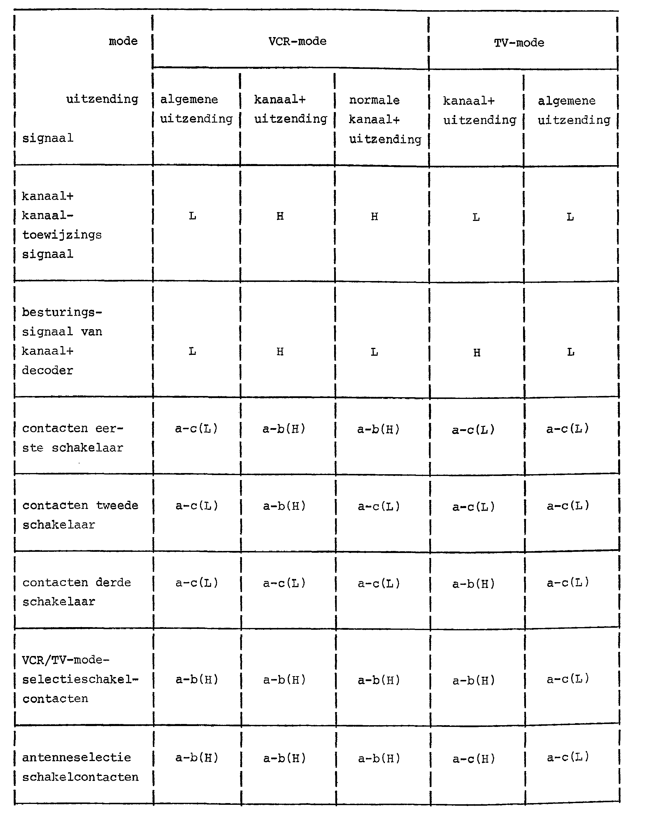
(De tekens tussen haakjes geven bijbehorende logische niveau's aan van de schakelbesturingssignalen).(The characters in brackets indicate corresponding logic levels of the shift control signals).
In de bovenstaande tabel gaat het niveau van het kanaal+ kanaalbestemmingssignaal CP omlaag wanneer de algemene uitzending wordt gekozen in de VCR-mode, en aldus gaat het eerste be-sturingssignaal ook omlaag zoals hierboven is beschreven, waardoor de contacten a en c van de eerste schakelaar 5 met elkaar worden verbonden. Ook worden, wanneer het besturingssignaal van de kanaal+ decoder 3 omlaag gaat, de transistoren 40 en 43 uitgeschakeld en het tweede besturingssignaal, dat het collectoruitgangssignaal van de transistor 40 is, gaat omlaag, waardoor de contacten a en c van de tweede schakelaar 6 met elkaar worden verbonden. Aldus wordt het algemene zendsignaal dat wordt ontvangen door de antenne 10 geleverd aan de videosignaalverwerkingsketen 14 via de afstemsignaalin-gang T van de ingangsselectieschakelaar 15.In the above table, the level of the channel + channel destination signal CP goes down when the general broadcast is selected in VCR mode, and so the first control signal also goes down as described above, causing contacts a and c of the first switch 5 are connected together. Also, when the control signal of the channel + decoder 3 goes down, the transistors 40 and 43 turn off and the second control signal, which is the collector output signal of the transistor 40, goes down, causing the contacts a and c of the second switch 6 to mingle be connected. Thus, the general transmit signal received by the antenna 10 is supplied to the video signal processing circuit 14 through the tuning signal input T of the input selection switch 15.
Anderzijds wordt, wanneer het VCR/TV-modeselectie-signaal omhoog gaat en het besturingssignaal van de kanaal+ decoder 3 omlaag gaat, de transistor 47 uitgeschakeld en gaat daarbij het derde besturingssignaal, dat het collectoruitgangssignaal van de transistor 47 is, omlaag. Aldus worden de contacten a en c van de derde schakelaar 7 met elkaar verbonden en wordt het uitgangssignaal van de videosignaalverwerkingsketen 14 geleverd aan de video-uitgangsaansluitklem 33. Op dat ogenblik wordt het vierde bestu-ringsuitgangssignaal vanuit de schakelbesturingsketen 4, dat het VCR/TV-modeselectiesignaal is van hoog niveau, geleverd aan de VCR/TV-modeselectieschakelaar 25 via een diode 52 en worden dus de contacten a en c van de VCR/TV-modeselectieschakelaar 25 met elkaar verbonden, waardoor het videosignaal dat aan de video-uitgangsaan-sluitklem 32 is verschaft, toegevoerd aan de videosignaalverwerkingsketen in de TV-sectie 2.On the other hand, when the VCR / TV mode selection signal goes up and the control signal of the channel + decoder 3 goes down, the transistor 47 turns off, thereby decreasing the third control signal, which is the collector output signal of the transistor 47. Thus, the contacts a and c of the third switch 7 are connected together and the output of the video signal processing circuit 14 is supplied to the video output terminal 33. At that time, the fourth control output signal from the switching control circuit 4, which is the VCR / TV mode selection signal is high level, supplied to the VCR / TV mode selection switch 25 via a diode 52 and thus the contacts a and c of the VCR / TV mode selection switch 25 are connected to each other, thereby supplying the video signal to the video output terminal. terminal 32 is provided, supplied to the video signal processing circuit in the TV section 2.
Ook wordt het kanaal+ kanaalbestemmingssignaal CP hoog, zoals is getoond in de tabel, wanneer het kanaal+ zendkanaal wordt geselecteerd door de afstemeenheid 12 in de VCR-mode. Bijgevolg gaat het eerste besturingssignaal ook omhoog en worden de contacten a en b van de eerste schakelaar met elkaar verbonden, waardoor het kanaal+ zendsignaal dat is ontvangen via de afstemeenheid 12 en de demodulator 13, wordt geleverd aan de kanaal+ decoder 3.Also, the channel + channel destination signal CP becomes high, as shown in the table, when the channel + transmit channel is selected by the tuner 12 in the VCR mode. Consequently, the first control signal also goes up and the contacts a and b of the first switch are connected together, thereby supplying the channel + transmit signal received through the tuner 12 and the demodulator 13 to the channel + decoder 3.
Zoals hierboven is beschreven zet de kanaal+ decoder 3 het ontvangen kanaal+ zendsignaal om in het normale zendsignaal.As described above, the channel + decoder 3 converts the received channel + transmission signal into the normal transmission signal.
Op dat ogenblik wordt het besturingssignaal van de kanaal+ decoder 3 hoog en worden de transistoren 40 en 43 ingeschakeld door het kanaal+ kanaalbestemmingssignaal van hoog niveau. Aldus wordt het tweede besturingssignaal van hoog niveau, dat het collectoruitgangssignaal is van de transistor 40, geleverd aan de tweede schakelaar 6 en de contacten a en b van de tweede schakelaar 6 worden met elkaar verbonden.At that time, the control signal of the channel + decoder 3 goes high and transistors 40 and 43 are turned on by the high level channel + channel destination signal. Thus, the second high level control signal, which is the collector output signal of the transistor 40, is supplied to the second switch 6 and the contacts a and b of the second switch 6 are connected together.
Bijgevolg wordt het kanaal+ zendsignaal dat is omgezet in het normale zendsignaal door de kanaal* decoder 3 geleverd aan de videosignaalverwerkingsketen 14 via de contacten a en b van de tweede schakelaar 6 en de afstemingang T van de ingangsselectie-schakelaar 15, De niveau's van het derde en het vierde besturingssignaal zijn dezelfde als wanneer de algemene uitzending wordt geselecteerd.Consequently, the channel + transmit signal converted to the normal transmit signal by the channel * decoder 3 is supplied to the video signal processing circuit 14 through the contacts a and b of the second switch 6 and the tuning input T of the input selector switch 15, The levels of the third and the fourth control signal are the same as when the general broadcast is selected.
Wanneer een normale kanaal+ uitzending wordt ontvangen in de VCR-mode, worden de contacten a en b van de eerste schakelaar 5 met elkaar verbonden gelijk wanneer de kanaal+ uitzending wordt ontvangen zoals hierboven is beschreven en het ontvangen zendsignaal wordt geleverd aan de kanaal+ decoder 3. Echter wordt, aangezien er geen signaal wordt omgezet door de kanaal+ decoder 3, het besturingssignaal daarvan laag en worden de toestanden van de contacten voor elke schakelaar op dezelfde wijze bepaald als wanneer de algemene uitzending wordt ontvangen.When a normal channel + broadcast is received in the VCR mode, the contacts a and b of the first switch 5 are connected together when the channel + broadcast is received as described above and the received broadcast signal is supplied to the channel + decoder 3. However, since no signal is converted by the channel + decoder 3, its control signal becomes low and the states of the contacts for each switch are determined in the same manner as when the general broadcast is received.
Anderzijds wordt, wanneer de kanaal+ uitzending wordt ontvangen in de TV-mode, het kanaal+ kanaalbestemmingssignaal laag en worden de contacten a en c van de eerste schakelaar 5 met elkaar verbonden, waardoor de ingang van de kanaal+ decoder 3 wordt verbonden met de uitgang van de demodulator 23 in de TV-sectie. In dit geval moet het zendkanaal dat wordt geselecteerd in de VCR-sec-tie 1 niet het kanaal* zendkanaal zijn.On the other hand, when the channel + broadcast is received in the TV mode, the channel + channel destination signal becomes low and the contacts a and c of the first switch 5 are connected together, connecting the input of the channel + decoder 3 to the output of the demodulator 23 in the TV section. In this case, the transmit channel selected in VCR section 1 must not be the channel * transmit channel.
Terwijl het kanaal+ zendsignaal dat is gedemodu-leerd door de demodulator 23 in de TV-sectie 2, wordt geleverd aan de kanaal* decoder 3 om te worden omgezet in het normale kanaal+ zendsignaal, wordt het besturingssignaal van de kanaal+ decoder 3 hoog en geleverd aan de schakelbesturingsketen 4.While the channel + transmit signal demodulated by the demodulator 23 in the TV section 2 is supplied to the channel * decoder 3 to be converted to the normal channel + transmit signal, the control signal of the channel + decoder 3 becomes high and supplied to the switching control chain 4.
In dat geval worden de transistoren 43 en 40 uitgeschakeld door het kanaalt kanaalbestemmingssignaal van laag niveau en wordt derhalve het tweede besturingssignaal van laag niveau geleverd aan de tweede schakelaar 6 waardoor de contacten a en c daarvan met elkaar worden verbonden. Ook wordt de transistor 47 ingeschakeld wanneer het VCR/TV-modeselectie-uitgangssignaal vanuit de kanaal+ decoder omlaag gaat en het vierde besturingssignaal van hoog niveau, dat het collectoruitgangssignaal is van de transistor 47, wordt geleverd aan de VCR/TY-modeselectieschakelaar 25 via de diode 51, en het derde besturingssignaal van hoog niveau dat ook het collectoruitgangssignaal van de transistor 47 is, wordt geleverd aan de derde schakelaar 7 via de diode 54. Aldus worden de contacten a en b van de VCR/TV-modeselectieschakelaar 25 en van de derde schakelaar 7 respectievelijk met elkaar verbonden, waardoor het kanaalt zendsignaal dat is omgezet door de kanaalt decoder wordt geleverd aan de videosignaalverwerkingsketen 24 in de TV-sec-tie via de derde schakelaar en de VCR/TV-modeselectieschakelaar, respectievelijk 7 en 25.In that case, transistors 43 and 40 are turned off by the low level channel destination signal, and therefore the second low level control signal is supplied to the second switch 6, thereby connecting the contacts a and c thereof. Also, the transistor 47 turns on when the VCR / TV mode selection output signal from the channel + decoder goes down and the fourth high level control signal, which is the collector output signal of transistor 47, is supplied to the VCR / TY mode selection switch 25 via the diode 51, and the third high level control signal which is also the collector output signal of the transistor 47 is supplied to the third switch 7 through the diode 54. Thus, the contacts a and b of the VCR / TV mode selector switch 25 and the third switch 7 connected together, whereby the channel transmit signal converted by the channel decoder is supplied to the video signal processing circuit 24 in the TV section via the third switch and the VCR / TV mode selection switch, 7 and 25, respectively.
Wanneer de algemene uitzending in de TV-mode wordt ontvangen, worden de toestanden van de contacten voor de eerste, tweede en derde schakelaar 5, 6 en 7 op dezelfde wijze bepaald als wanneer de algemene uitzending wordt ontvangen in de VCR-mode, met de uitzondering dat de contacten a en c van de VCR/TV-modeselectieschakelaar 25 met elkaar worden verbonden door het VCR/TV-modese-lectiesignaal van laag niveau, zoals kan worden gezien in de tabel. Aldus wordt het algemene zendsignaal dat wordt ontvangen door de antenne 10 geleverd aan de videosignaalverwerkingsketen 24 via de afstemeenheid 22 en de demodulator 23 in de TV-sectie 2.When the general broadcast is received in the TV mode, the states of the contacts for the first, second and third switches 5, 6 and 7 are determined in the same manner as when the general broadcast is received in the VCR mode, with the except that the contacts a and c of the VCR / TV mode selection switch 25 are connected together by the low level VCR / TV mode selection signal, as can be seen in the table. Thus, the general transmission signal received by the antenna 10 is supplied to the video signal processing circuit 24 through the tuner 22 and the demodulator 23 in the TV section 2.
Uit het voorgaande zal duidelijk zijn dat de onderhavige uitvinding het voordeel biedt dat de kanaal+ uitzending kan worden bekeken niet slechts in de VCR-mode maar ook in de TV-mode door het automatisch schakelen van de kanaal+ decoder, en dat aldus het ongemak dat wordt veroorzaakt door het met de hand moeten ver binden van de kanaal+ decoder met de VCR of met de TV telkens wanneer het kanaal+ zendsignaal wordt ontvangen, wordt vermeden.From the foregoing, it will be appreciated that the present invention offers the advantage that the channel + broadcast can be viewed not only in the VCR mode but also in the TV mode by automatically switching the channel + decoder, thus reducing the inconvenience caused by having to manually connect the channel + decoder to the VCR or to the TV each time the channel + transmission signal is received is avoided.
Ofschoon de onderhavige uitvinding is beschreven en geïllustreerd onder verwijzing naar de voorkeursuitvoeringen daarvan, zullen zij die terzake kundig zijn begrijpen dat verschillende veranderingen in de vorm en in details kunnen worden gemaakt zonder het kader van de uitvinding te overschrijden.Although the present invention has been described and illustrated with reference to the preferred embodiments thereof, those skilled in the art will understand that various changes in form and details can be made without exceeding the scope of the invention.
Claims (2)
Priority Applications (4)
| Application Number | Priority Date | Filing Date | Title |
|---|---|---|---|
| NL8902007A NL194657C (en) | 1989-08-04 | 1989-08-04 | Channel + decoder switching circuit for video cassette recorder devices. |
| DE3926079A DE3926079A1 (en) | 1989-08-04 | 1989-08-07 | TELEVISION STANDARD DECODER SWITCH ARRANGEMENT FOR VIDEO RECORDER |
| US07/390,193 US4995079A (en) | 1989-08-04 | 1989-08-07 | Canal+ decoder switching circuit for video cassette recorders |
| FR898910805A FR2650931B1 (en) | 1989-08-04 | 1989-08-11 | DECODER SWITCHING CIRCUIT FOR MAGNETOSCOPES |
Applications Claiming Priority (2)
| Application Number | Priority Date | Filing Date | Title |
|---|---|---|---|
| NL8902007 | 1989-08-04 | ||
| NL8902007A NL194657C (en) | 1989-08-04 | 1989-08-04 | Channel + decoder switching circuit for video cassette recorder devices. |
Publications (3)
| Publication Number | Publication Date |
|---|---|
| NL8902007A true NL8902007A (en) | 1991-03-01 |
| NL194657B NL194657B (en) | 2002-06-03 |
| NL194657C NL194657C (en) | 2002-10-04 |
Family
ID=19855143
Family Applications (1)
| Application Number | Title | Priority Date | Filing Date |
|---|---|---|---|
| NL8902007A NL194657C (en) | 1989-08-04 | 1989-08-04 | Channel + decoder switching circuit for video cassette recorder devices. |
Country Status (4)
| Country | Link |
|---|---|
| US (1) | US4995079A (en) |
| DE (1) | DE3926079A1 (en) |
| FR (1) | FR2650931B1 (en) |
| NL (1) | NL194657C (en) |
Families Citing this family (3)
| Publication number | Priority date | Publication date | Assignee | Title |
|---|---|---|---|---|
| FI90612C (en) * | 1992-03-11 | 1994-02-25 | Salon Televisiotehdas Oy | Method and decoder for decoding a coded video signal |
| EP0725491B1 (en) * | 1992-04-08 | 1999-06-23 | Koninklijke Philips Electronics N.V. | Video communication for interconnecting appliances that communicate using a control signal |
| DE4425526C2 (en) * | 1993-07-27 | 2001-02-15 | Samsung Electronics Co Ltd | Video recorder with a connection for a fee television decoder |
Citations (6)
| Publication number | Priority date | Publication date | Assignee | Title |
|---|---|---|---|---|
| EP0074810A2 (en) * | 1981-09-10 | 1983-03-23 | Sony Corporation | Subscription television system |
| US4439785A (en) * | 1980-11-17 | 1984-03-27 | Vvr Associates | Subscriber television system |
| US4456928A (en) * | 1980-08-08 | 1984-06-26 | Thomson-Brandt | Integrated interface circuit between a television receiver and its peritelevision connector |
| US4630133A (en) * | 1982-12-20 | 1986-12-16 | Zenith Electronics Corporation | VCR with total record/view flexibility |
| US4633302A (en) * | 1985-10-01 | 1986-12-30 | Control Data Corporation | Video cassette recorder adapter |
| US4636855A (en) * | 1983-03-09 | 1987-01-13 | Sony Corporation | Scrambled television signal receiver system |
Family Cites Families (5)
| Publication number | Priority date | Publication date | Assignee | Title |
|---|---|---|---|---|
| FR2543386B1 (en) * | 1983-03-21 | 1987-03-20 | Telediffusion Fse | METHODS AND DEVICES FOR SCRAMBLING AND SCRAMBLING FOR TELEVISION IMAGES |
| US4817142A (en) * | 1985-05-21 | 1989-03-28 | Scientific Atlanta, Inc. | Restoring framing in a communications system |
| FR2584556B1 (en) * | 1985-07-02 | 1987-09-18 | France Etat | METHOD FOR SCRAMBLING AND SCRATCHING TELEVISION IMAGES |
| US4924498A (en) * | 1988-04-29 | 1990-05-08 | Scientific Atlanta, Inc. | Method and apparatus for improving video scrambling and employing split snyc pulses |
| US4916736A (en) * | 1988-06-07 | 1990-04-10 | Macrovision Corporation | Method and apparatus for encrypting and decrypting time domain signals |
-
1989
- 1989-08-04 NL NL8902007A patent/NL194657C/en not_active IP Right Cessation
- 1989-08-07 US US07/390,193 patent/US4995079A/en not_active Expired - Lifetime
- 1989-08-07 DE DE3926079A patent/DE3926079A1/en active Granted
- 1989-08-11 FR FR898910805A patent/FR2650931B1/en not_active Expired - Lifetime
Patent Citations (6)
| Publication number | Priority date | Publication date | Assignee | Title |
|---|---|---|---|---|
| US4456928A (en) * | 1980-08-08 | 1984-06-26 | Thomson-Brandt | Integrated interface circuit between a television receiver and its peritelevision connector |
| US4439785A (en) * | 1980-11-17 | 1984-03-27 | Vvr Associates | Subscriber television system |
| EP0074810A2 (en) * | 1981-09-10 | 1983-03-23 | Sony Corporation | Subscription television system |
| US4630133A (en) * | 1982-12-20 | 1986-12-16 | Zenith Electronics Corporation | VCR with total record/view flexibility |
| US4636855A (en) * | 1983-03-09 | 1987-01-13 | Sony Corporation | Scrambled television signal receiver system |
| US4633302A (en) * | 1985-10-01 | 1986-12-30 | Control Data Corporation | Video cassette recorder adapter |
Non-Patent Citations (1)
| Title |
|---|
| IEEE TRANSACTIONS ON CONSUMER ELECTRONICS, vol. CE-33, nr. 1, februari 1987, bladzijden 28-29, IEEE, New York, US; D.J. LARGE et al.: "Interconnection subtleties of consumer products and cable" * |
Also Published As
| Publication number | Publication date |
|---|---|
| NL194657B (en) | 2002-06-03 |
| DE3926079A1 (en) | 1991-02-14 |
| FR2650931A1 (en) | 1991-02-15 |
| NL194657C (en) | 2002-10-04 |
| US4995079A (en) | 1991-02-19 |
| FR2650931B1 (en) | 1992-01-17 |
Similar Documents
| Publication | Publication Date | Title |
|---|---|---|
| KR0148018B1 (en) | Television signal switching system | |
| EP0817483A3 (en) | Television device having text data processing function | |
| EP0392552B1 (en) | Audio switching for an audio/video system having S-video capability | |
| KR19980703579A (en) | Multi-Standard Signal Receiver | |
| NL8902007A (en) | CHANNEL + DECODER SWITCH CHAIN FOR VIDEO CASSETTE REGISTRATION DEVICES. | |
| KR960007568B1 (en) | Switching circuit for vcr | |
| JP2924540B2 (en) | Television receiver | |
| CN1064778A (en) | The television receiver that contains picture-in-picture processor | |
| US6212326B1 (en) | Video tape or cassette recorder | |
| US5887109A (en) | Recording apparatus capable of selecting a CATV broadcast without operating a CATV decorder and method therefor | |
| JP2998412B2 (en) | Satellite broadcast receiver | |
| JP2642795B2 (en) | TV with built-in BS tuner | |
| KR950007155Y1 (en) | Jack terminal for changing output in television | |
| KR920004340Y1 (en) | Diversion switch with tv signal | |
| JPS6117536Y2 (en) | ||
| KR100257257B1 (en) | Television having a mode transition function | |
| JP2790161B2 (en) | Satellite receiver | |
| JP2616611B2 (en) | Satellite receiver | |
| JPH0441664Y2 (en) | ||
| KR100230497B1 (en) | Tvcr | |
| KR960013035A (en) | TV's Common Receiver | |
| KR960016397A (en) | Broadcast Channel Memory Circuit in Television | |
| JPH04361495A (en) | Changeover circuit | |
| JPH04361487A (en) | Video signal automatic changeover circuit | |
| JPS6352395A (en) | Tape recorder with multiple pin connector |
Legal Events
| Date | Code | Title | Description |
|---|---|---|---|
| A1C | A request for examination has been filed | ||
| V4 | Discontinued because of reaching the maximum lifetime of a patent |
Effective date: 20090804 |