NL2010512C2 - Image filtering for microscopy. - Google Patents
Image filtering for microscopy. Download PDFInfo
- Publication number
- NL2010512C2 NL2010512C2 NL2010512A NL2010512A NL2010512C2 NL 2010512 C2 NL2010512 C2 NL 2010512C2 NL 2010512 A NL2010512 A NL 2010512A NL 2010512 A NL2010512 A NL 2010512A NL 2010512 C2 NL2010512 C2 NL 2010512C2
- Authority
- NL
- Netherlands
- Prior art keywords
- frequency
- image
- filter module
- filter
- lukosz
- Prior art date
Links
Classifications
-
- G—PHYSICS
- G06—COMPUTING; CALCULATING OR COUNTING
- G06T—IMAGE DATA PROCESSING OR GENERATION, IN GENERAL
- G06T3/00—Geometric image transformation in the plane of the image
- G06T3/40—Scaling the whole image or part thereof
- G06T3/4053—Super resolution, i.e. output image resolution higher than sensor resolution
Landscapes
- Physics & Mathematics (AREA)
- General Physics & Mathematics (AREA)
- Engineering & Computer Science (AREA)
- Theoretical Computer Science (AREA)
- Image Processing (AREA)
- Microscoopes, Condenser (AREA)
Abstract
Filtering module for transforming one or more input images into at least one synthesized output image is described wherein one or more input images are generated by an optical- digital imaging system associated with a non-filtered optical transfer function and wherein said filter module comprises: one or more filtering functions that are obtained from minimizing at least part of an objective function, wherein said objective function is a sum of terms, preferably a weighted sum of terms, wherein a term comprises one or more harmonic components of said one or more input images and one or more associated harmonic components of said output image, and, wherein at least part of said terms is minimum if the ratio between said one or more harmonic components of said one or more input images and output image matches the ratio between a (spatial) frequency bound of said non-filtered optical transfer function and said non-filtered optical transfer function.
Description
Image filtering for microscopy Field of the invention
The invention generally relates to image filtering for microscopy such as structured illumination microscopy or fluorescence microscopy, and, in particular, though not exclusively, to an image filtering module and filtering method for use in microscopy, a computer-implemented method for generating such filter and to a software program product using such method.
Background of the invention
In structured illumination microscopy (SIM) the resolution of conventional (fluorescence) microscopy may be substantially doubled by reconstructing an image on the basis of a sequence of digital images of the object wherein these images are taken by illuminating the object with different spatially varying periodic illumination fields. For example, for each image the illumination fields (typically a set of equidistant stripes) may be displaced and/or rotated.
A conventional SIM imaging system as for example explained in the article by Gustafsson et al., "Surpassing the lateral resolution limit by a factor of two using structured illumination microscopy," Journal of Microscopy, vol. 98, pp. 82-87 (2000), comprises an optical microscope and a digital imaging system for generating digital images of (fluorescent) objects on the basis of spatially varying periodic illumination fields. The digital imaging system may further comprise an image processor configured for reconstructing a high-resolution image on the basis the images.
During reconstruction the image processor may use a generalized Wiener filter in order to improve the image quality. Δη example of such filter is described in M.G.L. Gustafsson, et al., "Three-Dimensional Resolution Doubling in Wide-Field Fluorescence Microscopy by Structured Illumination," Biophysical Journal, vol. 94, pp. 4957-4970 (2008). The generalized Wiener filter is characterized by a regularization parameter, which is a measure for the boost of high spatial frequencies compared to low spatial frequencies. However, in practice, it is difficult to determine an a priori setting for the regularization parameter.
Furthermore, for relatively low noise levels, the high spatial frequencies are boosted too much, thus generating image artifacts in the resulting image. The image of a straight edge may show fringes on the bright side of the edge ("edge ringing"). Also, the image of an isolated point may show a ring structure surrounding the image point where negative pixel values may occur. These negative pixel values are unnatural and undesirable. Further, a piecewise continuous object may show irregular line-like features in the bright parts of the image, which do not represent real features of the object. In some cases, part of these problems may be alleviated by a so-called apodization filter, which suppresses the high spatial frequencies. Such a filter however requires careful balancing of the parameters of the apodization filter with the settings of the generalized Wiener filter which in practice is difficult to achieve.
Thus, there is a need for filters and filtering methods, which alleviate some of the problems discussed above. In particular there is a need for an improved filter and filtering methods that may be used in microscopy such as florescence and SIM microcopy and that are simple and robust against variations of parameter settings and noise level and which may provide reconstruction of images that represent the object with improved fidelity (i.e. which eliminates at least part of the aforementioned image artifacts).
Summary of the invention
It is an objective of the invention to reduce or eliminate at least one of the drawbacks known in the prior art. In one aspect the invention may relate to a filtering module for transforming one or more input images into at least one synthesized output image, wherein said one or more input images are generated by an optical-digital imaging system associated with a non-filtered optical transfer function. The filter module may comprise: one or more filtering functions that are obtained by minimizing at least part of an objective function, wherein said objective function is a sum of terms, preferably a weighted sum of terms, wherein a term comprises one or more harmonic components of said one or more input images and one or more associated harmonic components of said output image, and, wherein at least part of said terms is minimum if the ratio between said one or more harmonic components of said one or more input images and said at least one output image matches the ratio between a (spatial) frequency bound of said non-filtered optical transfer function and said non-filtered optical transfer function.
The use of the one or more filters functions that are obtained by minimizing an objective function which depends on the optical transfer function and a frequency bound provides a filter which is robust against variations in regularization parameter values and noise levels while generating an image with increased fidelity. The filter functions may be used to alter or modify the effective OTF of the whole imaging system. Deriving filter functions by minimizing an objective function as defined above allows for easy incorporation of various bounds that allow enhancement of certain favourable properties (resolution, contrast, sharpness, color balance, etc.) and/or suppression of artifacts and effects that deteriorate the image quality. Hence, the invention provides a very flexible way of using and constructing filter functions for different applications.
In an embodiment, said frequency bound may be based on the cut-off frequency of said non-filtered optical transfer function. In another embodiment, said bound may be based on a Lukosz bound for filtering out at least part of the negative output signals in at least part of said output image.
In an embodiment, said frequency bound may comprise at least one one dimensional Lukosz bound or a derivative thereof. In an embodiment, said at least one one-dimensional Lukosz bound may be defined by:

wherein is the cutoff frequency of the optical-digital imaging system. The use of the Lukosz bound decreases the occurrence of negative pixel values of the reconstructed image (in the spatial domain) and suppress or even eliminate other artifacts such as "edge ringing" that occur in filter methods of the prior art.
In an embodiment, said frequency bound may comprise a one-dimensional modified Lukosz bound or a derivative thereof, wherein said one-dimensional modified Lukosz bound may be defined by:

wherein β =1 or wherein β is selected from a value between 1 and 2, preferably between 1 and 1,2 and wherein ^c is the cutoff frequency of the imaging system. The modified Lukosz bound may suppress all negative pixel values in all practical circumstances so that the image quality is substantially improved.
In an embodiment, said frequency bound A(v) may comprise a two-dimensional Lukosz bound or a derivative thereof, wherein said two-dimensional Lukosz bound may be defined by:

wherein the cutoff frequency qc may depend on an azimuth angle φ and φ + π!2, wherein may be the frequency coordinates in a frame rotated over an angle φ, and wherein A,(v/^) is the one-dimensional (modified) Lukosz bound.
In an embodiment, said frequency bound A(v) may comprise an n-dimensional Lukosz bound or a derivative thereof, said n-dimensional Lukosz bound may be defined by:

wherein the cutoff frequencies qcj may depend on a rotation R, v’ = Rv , and wherein A,(v/#) may be the one dimensional (modified) Lukosz bound and where SO(n) is a group of rotations in n dimensions. Hence, the filtering module may be used in multi-dimensional imaging applications such as 3D microscopy.
In an embodiment, said frequency bound may be configured for suppressing low spatial frequencies for filtering one or more blurred parts in said output image. In an embodiment said frequency bound may be based on a Gaussian function defined by:

wherein c defines the strength of the low frequency suppression, c being selected between 0 and 1, wherein Dv determines the the boundary between the low and high-frequency region and wherein v is the spatial frequency. Accordingly, filter functions derived from the minimization of the objective function that includes a bound on the effective optical transfer function for predetermined low spatial frequencies may be used in order to filter out the out-of-focus blurred background.
In an embodiment, the objective function may comprise quadratic terms of harmonic components of the one or more input image and harmonic components of the output image.
In an embodiment, the objective function may further comprise a regularization term for regularization of at least part of said output image. In an embodiment, said regularization term may comprise any one or a combination of: the sum of the squares or the absolute value of pixel values of the output image, or, the sum of the squares or the absolute value of the gradient of pixel values of said output image, or the sum of squares or absolute value of higher order spatial derivatives of said output image.
In an embodiment, said filter module may comprise an
A
input for receiving one or more pass bands J,(v) . In an embodiment, said input may be configured for receiving K pass bands l = \,2,...K. In an embodiment, a pass band may be obtained by a linear combination of two or more images in the frequency domain.
In an embodiment, a pass-band may be associated with at least one of the harmonic components of the one or more spatially periodic illumination fields that are used in obtaining said one or more images. In an embodiment, a harmonic component may be associated with a spatial frequency vector q,, l- 1,2,...K ;
In an embodiment, said one or more pass-bands may be shifted by a distance and a direction associated with the spatial frequency vector q, of a harmonic component of the spatially periodic illumination field to which said one or more pass-bands are associated.
In an embodiment, the objective function L may comprise :

wherein j,(v) represents a pass band that may be provided as input to the filter; f(v) represents a filtered image in the frequency domain that may be obtained as the output of the filter; f(x) represents a function that satisfies /(x)>0 and /(x) = 0 if and only if x = 0; a, represents a weight coefficient associated with a pass band; H(v) ^ ^, v ' represents an optical A(v) presents a frequency bound; μ transfer function; v ' represents a regularization parameter; and, g(x) represents a regularization function.
In an embodiment, said weight coefficient cti may be equal to the product of the amplitude of a harmonic component with spatial frequency vector q, and a free parameter s,, wherein the free parameter s, takes a first value for one or more bands associated with non-zero spatial frequency and a second value for one or more bands assocaited with zero spatial frequency; wherein the ratio of the first and second value is referred to as the side-band height parameter s, preferably s being selected between 0.5 and 2.5, more preferably between 0.75 and 1.5. Hence, the side-band height parameter s is selected high enough in order to provide sufficient gain in resolution over the conventional resolution limit and low enough in order to prevent amplification of noise structures overlaying the genuine image data.
A
In an embodiment, one or more filter functions Ft(y), obtainable by minimizing the objective function, with respect to the harmonic components of the output of the filter T(y), may comprise:
In an embodiment, the optical-digital imaging system may comprise a microscope, preferably a fluorescence microscope or a trans-illuminated brightfield microscope.
In an embodiment said one or more filter functions may be configured to process a plurality of input images. In an embodiment, at least part of said input images may be obtained by using one or more spatially periodic illumination fields .
In an embodiment, said optical-digital imaging system may be configured to image two-dimensional object(s) or three-dimensional object(s).
In a further aspect, the invention may relate to a filter module as described above in a optical-digital imaging system, preferably a microscope for structured illumination microscopy, fluorescence microscopy, trans-illuminated brightfield microscopy or combinations thereof.
In yet a further aspect, the invention may relate to an optical-digital imaging system, preferably structured illumination microscopy, comprising a filtering module according as described above.
In another aspect, the invention may relate to a computer-implemented method for determining one or more filtering functions for transforming one or more input images into at least one synthesized output image, wherein said one or more input images are generated by an optical-digital imaging system associated with a non-filtered optical transfer function, wherein said method may comprise: determining one or more filtering function by minimizing at least part of an objective function, wherein said objective function is a sum of terms, preferably a weighted sum of terms, wherein a term comprises one or more harmonic components of said one or more input images and one or more associated harmonic components of said output image; and, wherein at least part of said terms is minimum if the ratio between said one or more harmonic components of said one or more input images and output image matches the ratio between a (spatial) frequency bound of said non-filtered optical transfer function and said non-filtered optical transfer function.
The disclosure may also relate to a computer program product, implemented on computer-readable non-transitory storage medium, wherein the computer program product may comprise software code portions configured for, when run a computer, executing the method steps according to any of the methods described in the present disclosure.
The disclosure will further be illustrated with reference to the attached drawings, which schematically show embodiments according to the disclosure. It will be understood that the disclosure is not in any way restricted to these specific embodiments.
Brief description of the drawings
Aspects of the disclosure will be explained in greater detail by reference to exemplary embodiments shown in the drawings, in which: FIG. 1 illustrates a structured illumination microscopy (SIM) method; FIG. 2 depicts a schematic of the effective transfer function of an optical-digital imaging system according to one embodiment of the disclosure; FIG. 3 shows examples of a bound on the effective optical transfer function of the optical-digital imaging system, the one-dimensional Lukosz bound and the modified Lukosz bound according to one embodiment of the disclosure; FIG. 4 shows exemplary cross sections of a two-dimensional modified Lukosz bound according to one embodiment of the disclosure; FIG. 5 shows an illustrative effective optical transfer function of the optical-digital imaging system, according to one embodiment of the disclosure; FIG. 6 shows an illustrative point spread function of the optical-digital imaging system according to one embodiment of the disclosure; FIG. 7 shows another illustrative point spread function of the optical-digital imaging system according to one embodiment of the disclosure; FIG. 8 shows an illustrative optical-digital imaging system, according to one embodiment of the disclosure; FIG. 9A shows an image obtained using a conventional SIM method applying the generalized Wiener filter; FIG. 9B shows an image obtained using the improved filter disclosed herein according to one embodiment of the disclosure .
Detailed description FIG. 1 depicts a schematic of a known structured illumination microscopy (SIM) method. The SIM method may be used in an optical-digital imaging system comprising an optical microscope and a digital imaging processor for processing images obtained by the optical microscope. An optical system like a microscope may be described in the frequency domain, wherein the image and the object may be considered as being composed of a sum of harmonic components, i.e., terms that vary periodically with the spatial coordinates of the object. Each harmonic component may be characterized by the direction of the periodic spatial variation and by the spatial frequency (i.e. the inverse of the spatial period of the harmonic component).
The so-called Optical Transfer Function (OTF) of the microscope may be defined as a ratio between the amplitude of one or more harmonic components of the image and the amplitude of the corresponding one or more harmonic components of the object. For fluorescent microscopy, the OTF is zero for spatial frequencies larger than a cut-off frequency 2 ΝΑΙ λ, where NA is the microscope objective numerical aperture and λ is the wavelength of the emitted light. The region in the frequency domain for which the OTF is non-zero may be referred to as the pass-band.
The microscope images are recorded using a digital camera and converted into digital images, which may be processed and filtered in order to enhance certain favourable properties such as resolution, contrast, sharpness, color balance, etc. This way the effective OTF of the whole imaging system (i.e. microscope and digital imaging system) may be altered.
The SIM image -'reconstruction method comprises certain image processing steps that result in an effective OTF
of an optical-digital imaging system that has a cut-off frequency of up to 4 ΝΑΙ λ, i.e. twice as high as the OTF of a conventional fluorescent microscope. Hence, based on the SIM technique an image may be reconstructed that has twice the resolution of a conventional microscope image.
The SIM method as depicted in Fig. 1 may start with the determination of the Fourier transform of the one or more input images. In one embodiment N Fourier transforms /„(v) j=l,...,N of N input images In(u) j=l,...,N (step 102) may be determined, wherein the images may be taken using one or more spatially periodically illumination fields 103χ-Ν. Linear combinations of the Fourier transforms may be determined in order to obtain K (K < N) individual pass-bands 105i_K in Fourier (frequency space) (step 104). A pass-band may comprise at least one of the K harmonic components appearing in the set of illumination patterns and a pass-band may have the same support in Fourier space as the OTF of the optical imaging system. In the next step 106, shifted pass-bands 107i_K may be generated by shifting the pass-bands 105i-K over a distance and in a direction given by the spatial frequency vector of the harmonic component of the set of illumination patterns to which the pass-band is assigned. The shifted pass-bands may be filtered (step 108) to enhance and/or suppress certain regions in Fourier space. In an embodiment, the image filter may vary between the different pass-bands. The thus filtered and shifted pass bands may be added (step 110) and an inverse Fourier transform is performed on the sum of the filtered and shifted pass bands so that a reconstructed image of enhanced resolution.
The filtering step 108 usually involves the use of a generalized Wiener filter and an apodization filter. The generalized Wiener filter may be characterized by a so-called regularization parameter, which provides a measure for the boost (enhancement) of high spatial frequencies compared to low spatial frequencies.
Determination of an a priori setting for the regularization parameter is however difficult to accomplish in practice, so that a user or an automated system may have difficulty in order to set this parameter to a correct setting. Further, when using a generalized Wiener filter at relatively low noise levels, the high spatial frequencies may be enhanced too much, thus generating image artefacts. The image of a straight edge for example may exhibit fringes on the bright side of the edge (usually referred-to as "edge ringing"). Also, the image of an isolated point may show a ring structure surrounding the image point such that negative pixel values can occur. These negative pixel values are unnatural as no a negative amount of light does not exist. Finally, a piecewise continuous object may show irregular line-like features in the bright parts of the image, which do not represent real features of the object.
Part of the above-mentioned problems may be alleviated by the so-called apodization filter, which suppresses the high spatial frequencies. Suppression however requires careful balancing of the parameter(s) of the apodization filter compared to the settings of the generalized Wiener filter. Such balance is difficult to achieve in practice.
To alleviate at least some of the problems described above, an improved filter design is provided, which is robust against variations in regularization parameter values and noise levels, and which may ensure the occurrence of negative pixel values of the reconstructed image (in the spatial domain) are substantially decreased or even eliminated.
It is submitted that although the embodiments in this disclosure are described in terms of operations in the frequency domain, one skilled in the art would appreciate that corresponding operations in the spatial domain may also be used to achieve the same purpose and effect.
FIG. 2 depicts a schematic representation of the effective transfer function of an optical-digital system according to one embodiment of the disclosure. The optical-digital imaging system may be characterized by an effective optical transfer function Heff comprising a native transfer function H(v) 202 of the (native) optical-digital system, a pass-band function P 204 for generating pass-bands and an image filter F(v) 206.
An object 0(u), e.g., a sample of interest, may be imaged by the optical-digital imaging system, thereby producing a set of N image(s) of the object. In one embodiment, N is at least 2. The plurality of acquired images
may be represented by the image set wherein n = 1,2,...,N
and wherein u represents the vector of spatial coordinates (which may be in two or three dimensions). The images may be obtained by using an optical microscope that is configured to illuminate the object with one or more different spatially periodic illumination fields. In that case, an input images may be associated with a particular spatially periodic illumination field (as e.g. depicted in Fig. 1). The Fourier I (v) transform of acquired images "v ' may be determined m order to process the images in the Fourier (frequency) domain.
The pass-band function P 204 may be configured to generate a set of pass-bands 1 = 1,2,...,K on the basis of ƒ (v) the Fourier transformed images "v ’ . A pass-band may be i (v) determined by linearly combining one or more images "v ' , e.g. K images, in the frequency domain, wherein K is less than or equal to N. A pass-band may be associated with one of the K harmonic components of spatially periodic illumination fields used in obtaining the images. Δ harmonic component may be
Ü ƒ — 1 O V
associated with a spatial frequency vector , 1 ’ .
Further, a pass-band may be shifted by a distance and a direction associated with the spatial frequency vector ^ of the harmonic component of the spatially periodic illumination field to which the pass-band is associated. Hereunder, the to- be reconstructed image may be represented by and its T(v)
Fourier transform may be represented by v ' .
To alleviate some of the problems of the generalized Wiener filter, an improved filter design for the image filter F(y) 206 is provided. Improving the image quality may include imposing a predetermined (frequency) bound A(v) on the effective optical transfer function of the optical-digital imaging system. If the effective optical transfer function meets the desired bound an image may be obtained with improved characteristics .
To that end, in one embodiment, the improved image filter F(v) 206 for processing the pass-bands (the input of the filter) in order to obtain the reconstructed image (the output of the filter) may be determined by minimizing an objective function L:
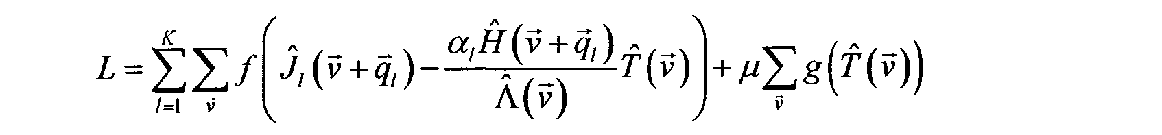
Here, f(x) is a function that satisfies f(x)>0 and with ƒ(x) = 0 if and only if x = 0. In one embodiment, ƒ(x) may be defined as |x|2. The function f(x) may be defined in various ways. In an embodiment, the objective function may be a weighted sum of harmonic components of the (pixel values of the) input image and harmonic components of the (pixel values of the) output image. In another embodiment, the objective function may comprise quadratic terms of the (pixel values of the) input image and harmonic components of the (pixel values of the) output image.
The second term of the objective function L may be referred to as the regularization term wherein μ is defined as the regularization parameter. In one embodiment, the function g(x) of the regularization term may be defined as: #(^(ν)Ην^(ν)Γ wherein the power value may be g = 1,2,... and wherein the power value may be p = 0,1,2,.... In real space, the p-th power of v may indicate the p-th order spatial derivative Vp. For example, p = 0 may define |x|q in real space, p = 1 may define j Vx jq, p = 2 may define | V2x |q, etc. Other forms of the regularization function, including the sum of terms described above, and a plurality of regularization parameters may be envisioned as well.
The regularization term may include any one of or a combination of any of the following: a sum of squares or an absolute value of values of the output of the image processing function; a sum of squares or an absolute value of a gradient of the values of the output of the image processing function; and/or, a sum of squares or an absolute value of a higher order spatial derivative of the output of the image processing function. Linear combinations of such terms are also envisioned.
The displacements of the pass-bands may be represented by the spatial frequency vectors q, associated with each pass-bands. A pass-band may be assigned a weight coefficient eg.. In one embodiment, the objective function may include a weighted sum of harmonic components of the input of the filter and the output of the filter. The weight coefficient eg. may be equal to the product of: the amplitude of the harmonic component with spatial frequency vector q, in the periodic illumination pattern and a free parameter si.
In one embodiment, the free parameter si may take first value for one or more bands (or all bands) centered around a non-zero spatial frequency and second value for one or more bands (or all bands) centered around a zero spatial frequency. The ratio of the first and second values may be referred to as the side-band height parameter s. This ratio has a significant effect on the quality of the resulting image. Preferably, the side-band height parameter s is selected high enough in order to provide sufficient gain in resolution over the conventional resolution limit and low enough in order to prevent amplification of noise structures overlaying the genuine image data. In an embodiment, the sideband height parameter may be selected in a range between 0.5 and 2.5, preferably between 0.6 and 2, more preferably between 0.7 and 1.5.
In one embodiment, the power values p and q may be selected as p = 1 and q = 2, however other values for p and q may also be used. In that case, the objective function may take the form:
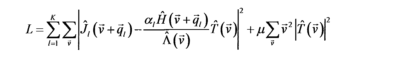
From the construction of the objective function, it may determined that the objective function is minimized when the ratio of the output m of the image filter and the input J,(y) of the filter is substantailly equal to the ratio of the bound A(v) on the transfer function of the optical-digital imaging system and the optical transfer function H(v) of the microscope.
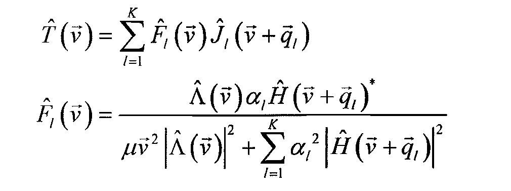
Accordingly, a filter 206 may be derived by minimizing the objective function with respect to the components of the Fourier transform of the reconstructed image T(v), which gives:
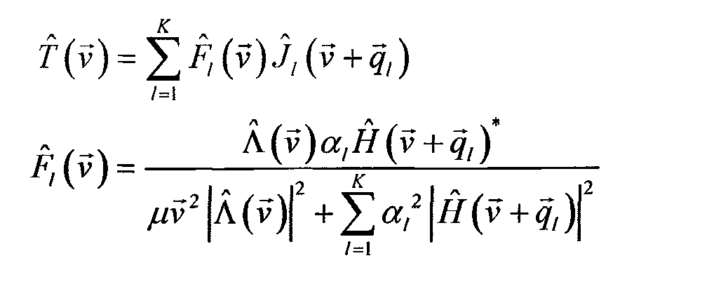
Hence, pass-band filter functions (in short referred to as filter functions) may be used to modify the input signal of the filter, the pass-bands. In particular, the pass-bands J,(v) may be provided as an input to the pass-band filter functions F,(v) (which collectively referred to as the filter 206). Here a pass-band may be determined by: J,(v) = alH(v)0(v + qI) where is the Fourier transform of the object function . For example, in the case of fluorescence microscopy, the object function may be the fluorescene object function associated with the object of interest. The fluorescence function may be regarded as a measure of the local concentration of fluorescent molecules. Other object functions for other types of microscopy may be envisioned as well.
The reconstructed image m may be obtained as the output of the image processing filter F,(v) :
An inverse Fourier transform on the output of the image processing filter may be performed to obtain a reconstructed image T(a) for human visual inspection. The resolution of the reconstructed image has doubled by the SIM
technique when compared to the resolution of an image determined by a non-SIM microscope. Accordingly, an effective OTF of the entire optical-digital system may be given by:
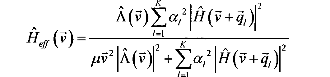
By construction, this effective OTF satisfies the bound on the effective optical transfer function for any value of the regularization parameter, because:

Because the effective optical transfer function of the optical-digital imaging system satisfies the bound on the effective optical transfer function, certain desirable characteristics of the inverse Fourier transform of the reconstructed image may be achieved.
In one embodiment, the bound on the effective transfer function may be based on the cutoff frequency of the (optical) imaging system. More specifically, in an embodiment, the bound on the effective transfer function may be based on the so-called Lukosz-bound as described by Lukosz in "Übertragung Nicht-negativer Signale Durch Lineare Filter" published in Journal of Modern Optics, vol. 9, pp. 335-364 (1962). This bound may be selected in the SIM filter design in order to reduce the negative pixel values in the reconstructed image in the spatial domain. The Lukosz-bound and improved versions of the Lukosz-bound (the so-called modified Lukosz-bound) are described in more detail with reference to Fig. 3.
This result is achieved irrespective of the value of the regularization parameter. This advantage is significant because in practice an a priori value for the regularization parameter is hard to determine. Moreover, no additional parameters need to be introduced in order to achieve the desired apodization effect.
The generalized (prior art) Wiener filter functions in conventional SIM are given by:

The disclosed improved image processing filter differs from the prior art generalized Wiener filter because the prior art generalied Wiener filter has an improper boost of higher spatial frequencies, e.g., in the case when the value of the regularization parameter is very small. In that case the Lukosz-bound is not satisfied, leading to image artifacts in the reconstructed image. These effects and the improved result are illustrated in more detail with reference to FIG. 9A and 9B.
It is submitted that the above-described operations in the frequency domain may have a corresponding set of operations in the spatial domain. In the spatial domain, suitable linear combinations of the N acquired images may be determined in order to construct K pass band images by J, (u) with 1 = 1,2,..., K. The pass band images may be multiplied with harmonic functions of the spatial coordinates. The direction and period of the harmonic variations are characterized by the spatial frequency vector of the corresponding pass band image. Subsequently, the modulated pass-band images may be convolved with suitable filter functions by and added to obtain the reconstructed image T{u) .
It is submitted that the invention is not limited to the exmaple in Fig. 2 and other bounds than the (modified) Lukosz bound (as discussed hereunder) may be imposed on the effective optical transfer function (e.g. enhancing or suppressing certain spatial frequencies) in order optimize a characteristic of the image. For example, light obtained from out-of-focus layers in an image may be captured by the optical-digital system which give rise to a blurry background. This background image is composed primarily of low spatial frequencies, the high spatial frequencies being nearly absent. An effective transfer function that suppresses low spatial frequencies may be used to filter out a substantial part of the out-of-focus blurred background. In one embodiment, a bound for blur suppression may be defined on the basis of a Gaussian function:

wherein 0 < c < 1 defines the strenght of the low frequency suppression, Dv determines the the boundary between the low and high-frequency region and v is the spatial frequency in one dimension. In two dimensions v is represented by the spatial frequency vector (vx,vy) wherein

Accordingly, filter functions derived from the minimization of the objective function that includes a bound on the effective optical transfer function for predetermined low spatial frequencies may be used in order to filter out the out-of-focus blurred background.
FIG. 3 shows illustrative bounds that may be used in the objective function including the conventional onedimensional Lukosz bound 302 and the modified Lukosz bound 304. For microscopy the conventional Lukosz bound and the modified Lukosz-bound depend on the cut-off spatial frequency vector of the native optical transfer function (OTF) of the imaging system (e.g. the microscope). For a ID-signal with a native OTF with highest spatial frequency qc for which the OTF is non-zero, the conventional Lukosz bound may be given by:

Hence, the Lukosz bound may be represented as a "staircase" function for the maximum (absolute value of the) OTF (i.e., a mathematical upper bound) as plotted as line 302 in FIG. 3. This bound may be used in the objective function in order to derive a set of filter function that substantially decrease the number of "negative" output signals.
In practice the conventional Lukosz bound does not provide a sufficient condition for non-negative output signals under all conditions. In order to avoid negative output (image) signals in substantially all practical circumstances a first modified Lukosz bound may be used:

In another embodiment, negative output signals may be avoided by satifying a second Lukoz bound:

wherein β may be referred to as a stretching exponent which may may be selected between 1 and 2, preferably between 1 and 1.2 (1 < β < 1.2) .
The first modified Lukosz-bound is plotted as line 304 in FIG. 3 and connects the lower point of the discontinuities in the conventional Lukosz-bound. In an embodiment, the modified Lukosz-bound may be generalized to two dimensions. The cut-off spatial frequency depends on the azimuth angle φ by a function qc{f) which parametrizes the exteriour boundary of the support of the OTF in spatial frequency space. In a further embodiment, for a given spatial v = ( V ,v ) frequency vector v v y> , the modified Lukosz-bound may be the minimum of the set of products of the ID (modified) Lukosz-bound along the two orthogonal directions given by azimuth angle φ and φ + π!2:

ν' = (ν' ,v' ) wherein the spatial frequency vector v x y! may V = (V,, vv) , be obtained from the spatial frequency vector ' ‘ y’ by , , v' = RU)v , rotation over an angle <p, i.e. v 7 . The formula may be generalized to n spatial dimensions:
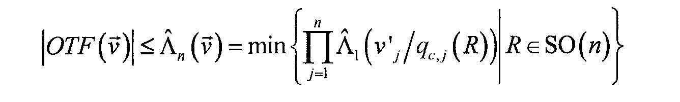
for v' = Rv r ancj wherein SO(n) is the group of rotations in n spatial dimensions, e.g., n=3. Hence, given the cut-off of the OTF in spatial frequency space, the modified Lukosz-bound may be evaluated.
For the case of 2D SIM, the support in Fourier space of the native OTF may be the union of the supports of the K
pass-bands displaced over the spatial frequency vectors ^ associated with the individual pass-bands. In an embodiment, the stripe illumination pattern may comprise a plurality, e.g. three harmonic components, rotated over three different angles, thereby determining seven (K=7) pass-bands wherein the cut-off frequency satisfies hexagonal rotation symmetry νΛΦ) = (ΐΛΦ + π/3)' anc* wherein:

with qm=2NA/X defining the optial cut-off resolution and q0=l/p defining the stripe spatial frequency where p is the distance between the stripes of the illumination pattern. These quantities satisfy q0 < qm as the' stripe pattern is made by interference between beams projected through the same objective lens with numerical aperture NA.
Two cross-sections 402,404 of an illustrative 2D SIM modified
Lukosz bound according to an embodiment of the disclosure is depicted in FIG. 4 for a parameter qo = 0.9qm.
The regularization parameter preferably measures the strength of the regularization term in the objective function. The value for the regularization parameter can in principle be chosen arbitrarily. A number of methods may be used for automatically setting the regularization parameter. Several of these methods are described by G.M.P. van Kempen and L.J. van Vliet in "The influence of the regularization parameter and the first estimate on the performance of Tikhonov regularized non-linear image restoration algorithms", Journal of Microscopy vol. 198, pp. 63-75, 2000, in the context of restoring or retrieving object information from a single noisy image.
One of these methods is the so-called cross-validation method, which may be used to find an appropriate value for the regularization parameter μ . In an embodiment, the cross-validation method may be adapted to the case of multiple input images as follows. One possible measure for the quality of the reconstructed image (given a certain object) may be determined by the mean-square error MSE:

The cross-validation function may be defined as a normalized form of the mean-square error MSE:

with the normalization constant:

Exemplary cross-sections 502,505 of an illustrative Lukosz bound filtered OTF for an 2D-SIM case are shown in Fig. 5. The illustrative case provides the shown OTF-support in spatial frequency space corresponding to SIM using a striped illumination pattern at three orientations and for a stripe spatial frequency that is 0.9 times the optical cut-off resolution.
FIG. 6 shows cross-sections 602,604 of a point spread function (PSF) associated with the Lukosz bound filtered OTF of Fig. 5. The PSF is defined as the inverse Fourier transform of the OTF. The PSF is the image of a single bright point object on a dark background. Ideally, the PSF approximates the reference PSF that would be obtained by simply scaling the coordinates with a factor ltq0. From Fig. 6 it can be seen that the PSF 602,604 substantially matches the reference PSF 606 with comparable side-lobe height and is nearly everywhere positive. The residual slightly negative PSF values may be washed out if blurring effects due to the finite pixel size are taken into account. When taking these corrections into account cross-sections 702,704 of a PSF as depicted in FIG. 7 are obtained.
FIG. 8 shows an illustrative optical-digital imaging system according to one embodiment of the disclosure. The optical-digital imaging system may comprise an (optical) imaging system 800 and an image processor 810. In one embodiment, the imaging system may be a microscope suitable for two-dimensional SIM imaging. In such an embodiment, a laser may be coupled into a fibre wherein the exit point of the fibre 801 may serve as a point source. The beam may be collimated by a first lens 802 and is split into two beams travelling at an angle with the optical axis by a grating 803. The beams pass a dichroic beam splitter 804 and are focused by a second lens 805 onto the entrance pupil of an objective lens 806. The objective lens may then produce two parallel beams travelling towards the sample/object on the backside of the cover slip 807 at equal but opposite angles. The interference pattern of the two beams forms a spatially periodic illumination pattern that may be used to illuminate the sample. The pattern may be rotated and/or shifted with respect to the sample by, e.g., rotating and shifting the grating.
The fluorescent light 808 emitted by the sample may be (partly) captured by the objective lens 806 and focused by the second lens 805. The light may then be reflected at dichroic beam splitter 804 due to its slightly larger wavelength compared to the excitation light, and converge towards the image point on the digital camera 809, which may generate digital images that may be processed by several digital image processing modules in a computer system. The operation of a three-dimensional SIM apparatus may use a similar system.
The image processor 810 may be part of a computer system that is configured to process the image data in the frequency domain as described with reference to Fig. 2. The processor may comprise a pass-band module 812 and a digital filter module 814 as described in detail with reference to Fig. 2-7 above. The image processor and its modules may be implemented as software, hardware or a combination of hardware and software.
The inputs and outputs and any intermediary data of the image processor may be stored in a storage device 816. The optical-digital system may further include a user interface module 818 allowing an operator to configure and control the image-processing module. Furthermore, in some embodiments, the computer system may include a display module 820 for rendering and/or displaying the reconstructed image.
FIG. 9A shows an image obtained using a conventional SIM method applying the generalized Wiener filter and FIG. 9B shows an image obtained using the filtering method according to one embodiment of the disclosure. The images are associated with a SIM microscope that has a Numerical Aperture NA = 1.25 and that images green light (λ = 500 nm). The acquired images are corrupted by shot noise, i.e. the noise that arises due to the nature of light detection with discrete amounts (photons). The actual number of detected photons per pixel is a noisy quantity. The average number of detected photons per pixel for repeated measurements provides the genuine image structure.
The first image shown in FIG. 9A provides an indication of artefacts that arise with insufficient apodization associated with the generalized Wiener filter. As can be seen from Fig. 9A, parts of the image pixels comprises negative pixel values. Further, other artefacts such as halo's surrounding bright objects and a noise structure are visible. When using the filtering method according to the invention in combination with the modified Lukosz-bound, at least a substantial part of these artefacts may be removed as can be seen in FIG. 9B. By satisfying the Lukosz-bound, the resulting reconstructed image is substantially non-negative and the amount and severity of artefacts have been significantly reduced.
Although the embodiment of acquiring at least two images using spatially periodic illumination fields are extensively discussed in the disclosure, it is envisioned that at least one image for the image processing module may be obtained with any suitable imaging system with a substantially uniform illumination pattern. It is stressed that the preceding discussion in no way limits the scope of the disclosure. In particular the disclosure applies equally well to the method of 3D-SIM for obtaining 3D images of the volume of a fluorescent sample. Also, it is not necessarily restricted to the case of SIM, it applies equally well to the case of conventional fluorescence microscopy as well as to the case of conventional trans-illuminated brightfield microscopy.
Various embodiments of the disclosure relating to at least the image processing module may be implemented as a program product for use with a computer system, where the program(s) of the program product define functions of the embodiments (including the methods described herein). In one embodiment, the program(s) can be contained on a variety of storage, i.e., non-transitory computer-readable storage media, where, as used herein, the expression "non-transitory computer readable storage media" comprises all computer-readable media, with the sole exception being a transitory, propagating signal. In another embodiment, the program(s) can be contained on a variety of transitory computer-readable storage media. Illustrative computer-readable storage media include, but are not limited to: (i) non-writable storage media (e.g., read only memory devices within a computer such as CD-ROM disks readable by a CD-ROM drive, ROM chips or any type of solid-state non-volatile semiconductor memory) on which information is permanently stored; and (ii) writable storage media (e.g., flash memory, floppy disks within a diskette drive or harddisk drive or any type of solid-state random-access semiconductor memory) on which alterable information is stored.
It is to be understood that any feature described in relation to any one embodiment may be used alone, or in combination with other features described, and may also be used in combination with one or more features of any other of the embodiments, or any combination of any other of the embodiments. Moreover, the disclosure is not limited to the embodiments described above, which may be varied within the scope of the accompanying claims.
Claims (20)
Priority Applications (2)
| Application Number | Priority Date | Filing Date | Title |
|---|---|---|---|
| NL2010512A NL2010512C2 (en) | 2013-03-22 | 2013-03-22 | Image filtering for microscopy. |
| PCT/NL2014/050178 WO2014148908A1 (en) | 2013-03-22 | 2014-03-21 | Image filtering for microscopy |
Applications Claiming Priority (2)
| Application Number | Priority Date | Filing Date | Title |
|---|---|---|---|
| NL2010512A NL2010512C2 (en) | 2013-03-22 | 2013-03-22 | Image filtering for microscopy. |
| NL2010512 | 2013-03-22 |
Publications (1)
| Publication Number | Publication Date |
|---|---|
| NL2010512C2 true NL2010512C2 (en) | 2014-09-24 |
Family
ID=48790530
Family Applications (1)
| Application Number | Title | Priority Date | Filing Date |
|---|---|---|---|
| NL2010512A NL2010512C2 (en) | 2013-03-22 | 2013-03-22 | Image filtering for microscopy. |
Country Status (2)
| Country | Link |
|---|---|
| NL (1) | NL2010512C2 (en) |
| WO (1) | WO2014148908A1 (en) |
Citations (3)
| Publication number | Priority date | Publication date | Assignee | Title |
|---|---|---|---|---|
| US20070269134A1 (en) * | 2006-05-22 | 2007-11-22 | Ge Healthcare Bio-Sciences Corp. | System and method for optical section image line removal |
| US20080292135A1 (en) * | 2005-11-01 | 2008-11-27 | Carl Zeiss Imaging Solutions Gmbh | Method and Device For Reconstructing Images |
| WO2011005239A1 (en) * | 2009-07-08 | 2011-01-13 | Freescale Semiconductor, Inc. | Device for forming a high-resolution image, imaging system, and method for deriving a high-spatial-resolution image |
-
2013
- 2013-03-22 NL NL2010512A patent/NL2010512C2/en not_active IP Right Cessation
-
2014
- 2014-03-21 WO PCT/NL2014/050178 patent/WO2014148908A1/en active Application Filing
Patent Citations (3)
| Publication number | Priority date | Publication date | Assignee | Title |
|---|---|---|---|---|
| US20080292135A1 (en) * | 2005-11-01 | 2008-11-27 | Carl Zeiss Imaging Solutions Gmbh | Method and Device For Reconstructing Images |
| US20070269134A1 (en) * | 2006-05-22 | 2007-11-22 | Ge Healthcare Bio-Sciences Corp. | System and method for optical section image line removal |
| WO2011005239A1 (en) * | 2009-07-08 | 2011-01-13 | Freescale Semiconductor, Inc. | Device for forming a high-resolution image, imaging system, and method for deriving a high-spatial-resolution image |
Non-Patent Citations (9)
| Title |
|---|
| FEDOSSEEV R ET AL: "Structured light illumination for extended resolution in fluorescence microscopy", OPTICS AND LASERS IN ENGINEERING, ELSEVIER, AMSTERDAM, NL, vol. 43, no. 3-5, 1 March 2005 (2005-03-01), pages 403 - 414, XP004629259 * |
| HARDIE R: "A Fast Image Super-Resolution Algorithm Using an Adaptive Wiener Filter", IEEE TRANSACTIONS ON IMAGE PROCESSING, IEEE SERVICE CENTER, PISCATAWAY, NJ, US, vol. 16, no. 12, 1 December 2007 (2007-12-01), pages 2953 - 2964, XP011196491 * |
| KARADAGLIC D ET AL: "Image formation in structured illumination wide-field fluorescence microscopy", MICRON, PERGAMON, OXFORD, GB, vol. 39, no. 7, 1 October 2008 (2008-10-01), pages 808 - 818, XP023781369 * |
| LUKOSZ W: "Optical Systems with Resolving Powers Exceeding the Classical Limit II", JOURNAL OF THE OPTICAL SOCIETY OF AMERICA, vol. 57, no. 7, 1 July 1967 (1967-07-01), pages 932, XP055047055 * |
| LUKOSZ W: "Optical Systems with Resolving Powers Exceeding the Classical Limit", JOURNAL OF THE OPTICAL SOCIETY OF AMERICA, AMERICAN INSTITUTE OF PHYSICS, NY; US, vol. 56, no. 11, 1 November 1961 (1961-11-01), pages 1463 - 1471, XP007918838 * |
| LUKOSZ W: "Übertragung Nicht-negativer Signale Durch Lineare Filter", JOURNAL OF MODERN OPTICS, TAYLOR AND FRANCIS, LONDON, GB, vol. 9, 1 January 1962 (1962-01-01), pages 335 - 364, XP009174952 * |
| NHAT NGUYEN ET AL: "Efficient Generalized Cross-Validation with Applications to Parametric Image Restoration and Resolution Enhancement", IEEE TRANSACTIONS ON IMAGE PROCESSING, IEEE SERVICE CENTER, PISCATAWAY, NJ, US, vol. 10, no. 9, 1 September 2001 (2001-09-01), XP011025837 * |
| QIANG WU ET AL, 1 January 2008, MICROSCOPE IMAGE PROCESSING, ELSEVIER/ACAD. PRESS, AMSTERDAM, article KRZEWINA L.G. AND KIM M.K.: "CHAPTER 17: Structured Illumination Imaging", pages: 469 - 497, XP009175036 * |
| SCHAEFER L H ET AL: "Structured illumination microscopy: artefact analysis and reduction utilizing a parameter optimization approach", JOURNAL OF MICROSCOPY, BLACKWELL SCIENCE, vol. 216, no. 2, 1 November 2004 (2004-11-01), pages 165 - 174, XP008084722 * |
Also Published As
| Publication number | Publication date |
|---|---|
| WO2014148908A1 (en) | 2014-09-25 |
Similar Documents
| Publication | Publication Date | Title |
|---|---|---|
| Forster et al. | Complex wavelets for extended depth‐of‐field: A new method for the fusion of multichannel microscopy images | |
| EP3942518B1 (en) | Systems and methods for image processing | |
| CN111145089B (en) | High-fidelity image reconstruction method, system, computer equipment and storage medium | |
| KR101161471B1 (en) | Optical imaging systems and methods utilizing nonlinear and/or spatially varying image processing | |
| JP7436379B2 (en) | Apparatus and method for baseline estimation in input signal data | |
| Shih et al. | Image enhancement using calibrated lens simulations | |
| Smith et al. | Structured illumination microscopy with noise-controlled image reconstructions | |
| US20150317508A1 (en) | Methods and Systems for Fourier Ptychographic Imaging | |
| WO2017181044A1 (en) | Optical phase retrieval systems using color-multiplexed illumination | |
| Fan et al. | A protocol for structured illumination microscopy with minimal reconstruction artifacts | |
| Forster et al. | Extended depth-of-focus for multi-channel microscopy images: a complex wavelet approach | |
| WO2015133593A1 (en) | Image processing method, image processing apparatus, image capturing apparatus, image processing program and non-transitory computer-readable storage medium | |
| Li et al. | PURE-LET deconvolution of 3D fluorescence microscopy images | |
| Bai et al. | Compressed blind deconvolution and denoising for complementary beam subtraction light-sheet fluorescence microscopy | |
| NL2010512C2 (en) | Image filtering for microscopy. | |
| Krylov et al. | A post-processing method for 3D fundus image enhancement | |
| CN112073603B (en) | Image processing apparatus, image capturing apparatus, image processing method, and storage medium | |
| WO2019185912A1 (en) | Apparatus and method for baseline estimation in input signal data | |
| Roels et al. | Image degradation in microscopic images: Avoidance, artifacts, and solutions | |
| Chobola et al. | DELAD: Deep Landweber-guided deconvolution with Hessian and sparse prior | |
| WO2022014579A1 (en) | Optical aberration correction program and optical wavefront estimation program | |
| CN117930497A (en) | Method and apparatus for light field microscopy | |
| Liu et al. | A robust alternating direction method for constrained hybrid variational deblurring model | |
| Hu et al. | HiLo Microscopy with Caustic Illumination | |
| Nguyen et al. | Generalized sparse variation regularization for large fluorescence image deconvolution |
Legal Events
| Date | Code | Title | Description |
|---|---|---|---|
| MM | Lapsed because of non-payment of the annual fee |
Effective date: 20160401 |