KR970010317B1 - Apparatus for detecting abnormality of oxygen sensor and controlling air/fuel ratio - Google Patents
Apparatus for detecting abnormality of oxygen sensor and controlling air/fuel ratio Download PDFInfo
- Publication number
- KR970010317B1 KR970010317B1 KR1019900008799A KR900008799A KR970010317B1 KR 970010317 B1 KR970010317 B1 KR 970010317B1 KR 1019900008799 A KR1019900008799 A KR 1019900008799A KR 900008799 A KR900008799 A KR 900008799A KR 970010317 B1 KR970010317 B1 KR 970010317B1
- Authority
- KR
- South Korea
- Prior art keywords
- air
- oxygen sensor
- fuel ratio
- abnormality
- output signal
- Prior art date
Links
Images


Classifications
-
- F—MECHANICAL ENGINEERING; LIGHTING; HEATING; WEAPONS; BLASTING
- F02—COMBUSTION ENGINES; HOT-GAS OR COMBUSTION-PRODUCT ENGINE PLANTS
- F02D—CONTROLLING COMBUSTION ENGINES
- F02D41/00—Electrical control of supply of combustible mixture or its constituents
- F02D41/02—Circuit arrangements for generating control signals
- F02D41/14—Introducing closed-loop corrections
- F02D41/1438—Introducing closed-loop corrections using means for determining characteristics of the combustion gases; Sensors therefor
- F02D41/1493—Details
- F02D41/1495—Detection of abnormalities in the air/fuel ratio feedback system
-
- F—MECHANICAL ENGINEERING; LIGHTING; HEATING; WEAPONS; BLASTING
- F02—COMBUSTION ENGINES; HOT-GAS OR COMBUSTION-PRODUCT ENGINE PLANTS
- F02D—CONTROLLING COMBUSTION ENGINES
- F02D41/00—Electrical control of supply of combustible mixture or its constituents
- F02D41/02—Circuit arrangements for generating control signals
- F02D41/18—Circuit arrangements for generating control signals by measuring intake air flow
-
- F—MECHANICAL ENGINEERING; LIGHTING; HEATING; WEAPONS; BLASTING
- F02—COMBUSTION ENGINES; HOT-GAS OR COMBUSTION-PRODUCT ENGINE PLANTS
- F02D—CONTROLLING COMBUSTION ENGINES
- F02D41/00—Electrical control of supply of combustible mixture or its constituents
- F02D41/02—Circuit arrangements for generating control signals
- F02D41/14—Introducing closed-loop corrections
- F02D41/1438—Introducing closed-loop corrections using means for determining characteristics of the combustion gases; Sensors therefor
- F02D41/1486—Introducing closed-loop corrections using means for determining characteristics of the combustion gases; Sensors therefor with correction for particular operating conditions
- F02D41/1488—Inhibiting the regulation
-
- F—MECHANICAL ENGINEERING; LIGHTING; HEATING; WEAPONS; BLASTING
- F02—COMBUSTION ENGINES; HOT-GAS OR COMBUSTION-PRODUCT ENGINE PLANTS
- F02D—CONTROLLING COMBUSTION ENGINES
- F02D41/00—Electrical control of supply of combustible mixture or its constituents
- F02D41/22—Safety or indicating devices for abnormal conditions
Landscapes
- Engineering & Computer Science (AREA)
- Chemical & Material Sciences (AREA)
- Combustion & Propulsion (AREA)
- Mechanical Engineering (AREA)
- General Engineering & Computer Science (AREA)
- Electrical Control Of Air Or Fuel Supplied To Internal-Combustion Engine (AREA)
- Combined Controls Of Internal Combustion Engines (AREA)
- Investigating Or Analyzing Materials By The Use Of Fluid Adsorption Or Reactions (AREA)
Abstract
내용없음.None.
Description
제1도는, 청구항(1)의 발명의 기본적 구성의 예시도.1 is an illustration of the basic configuration of the invention of claim (1).
제2도는, 청구항(2)의 발명의 기본적 구성의 예시도2 is an illustration of the basic configuration of the invention of claim (2)
제3도는, 청구항(3)의 발명의 기본적 구성의 예시도.3 is an illustration of the basic configuration of the invention of claim (3).
제4도는, 청구항(1)의 발명의 원리를 예시하는 설명도.4 is an explanatory diagram illustrating the principle of the invention of claim (1).
제5도는, 청구항(2)의 발명의 원리를 예시하는 설명도.5 is an explanatory diagram illustrating the principle of the invention of claim (2).
제6도는, 청구항(3)의 발명의 원리를 예시하는 설명도.6 is an explanatory diagram illustrating the principle of the invention of claim (3).
제7도는, 본 발명의 제1실시예 및 제5실시예의 시스템 구성도.7 is a system configuration diagram of the first and fifth embodiments of the present invention.
제8도는, 제1실시예의 처리를 나타내는 순서도.8 is a flowchart showing processing of the first embodiment.
제9도는, 제2실시예의 처리를 나타내는 순서도.9 is a flowchart showing processing of the second embodiment.
제10도는, 제3실시예의 처리를 나타내는 순서도.10 is a flowchart showing processing of the third embodiment.
제11도는, 제4실시예의 처리를 나타내는 순서도.11 is a flowchart showing processing of the fourth embodiment.
제12도는, 공연비와 이미션과의 관계를 나타내는 그래프.12 is a graph showing the relationship between the air-fuel ratio and emission.
제13도는, 공연비와 센서 출력과의 관계를 나타내는 그래프.13 is a graph showing the relationship between the air-fuel ratio and the sensor output.
제14도는, 청구항 4의 발명의 기본적 구성의 예시도.14 is an illustration of the basic configuration of the invention of
제15도는, 제5실시예의 처리를 나타내는 순서도.15 is a flowchart showing processing of the fifth embodiment.
제16도는, 제5실시예의 출력신호를 설명하는 그래프.Fig. 16 is a graph for explaining the output signal of the fifth embodiment.
제17도는, 제6실시예의 처리를 나타내는 순서도.17 is a flowchart showing processing of the sixth embodiment.
제18도는, 제6실시예의 출력신호를 설명하는 그래프.18 is a graph for explaining an output signal of the sixth embodiment.
제19도는, 제7실시예의 처리를 나타내는 순서도.19 is a flowchart showing processing of the seventh embodiment.
제20도는, 제7실시예의 출력 신호를 설명하는 그래프.20 is a graph for explaining an output signal of the seventh embodiment.
* 도면의 주요부분에 대한 부호의 설명* Explanation of symbols for main parts of the drawings
M1, M5, M10, M14 : 내연기관M1, M5, M10, M14: Internal combustion engine
M2, M6, M11, M15 : 산소센서M2, M6, M11, M15: Oxygen Sensor
M3, M7 : 공연비 설정수단 M4, M9, M13 : 이상판정수단M3, M7: air-fuel ratio setting means M4, M9, M13: abnormal determination means
M8 : 극치 검출수단 M12 : 공연비 제어수단M8: extreme value detection means M12: air-fuel ratio control means
M17 : 공연비 설정수단 2 : 엔진M17: air-fuel ratio setting means 2: the engine
3 : 전자제어장치(ECU) 4 : 실린더3: electronic control unit (ECU) 4: cylinder
5 : 피스톤 6 : 실린더헤드5: piston 6: cylinder head
7 : 연소실 8 : 점화 플러그7: combustion chamber 8: spark plug
9 : 흡기 밸브 10 : 흡기 포트9: intake valve 10: intake port
11 : 흡기관 12 : 서지 탱크11
14 : 스로틀 15 : 공기 정화기14: Throttle 15: Air Purifier
16 : 배기밸스 17 : 배기포트16: exhaust balance 17: exhaust port
18 : 배기매니폴드 19 : 촉매컨버터18: exhaust manifold 19: catalytic converter
20 : 배기관 21 : 점호기20: exhaust pipe 21: firing machine
22 : 분배장치 25 : 연료분사밸브22: distribution device 25: fuel injection valve
31 : 흡기기압센서 32 : 흡기온도센서31: Intake air pressure sensor 32: Intake air temperature sensor
33 : 스로틀위치센서 35 : 수온센서33: Throttle Position Sensor 35: Water Temperature Sensor
36 : 산소센서 37 : 부산소센서36: oxygen sensor 37: oxygen sensor
38 : 기통판별센서 39 : 회전수센서38: cylinder discrimination sensor 39: speed sensor
40 : 첵램프40: shock lamp
본 발명은 내연기관의 공연비를 피이드백(feed back), 제어하는 공연비 제어장치에 관한 것이다.The present invention relates to an air-fuel ratio control apparatus for feeding back and controlling the air-fuel ratio of an internal combustion engine.
종래로부터 내연기관의 배기가스중의 이미션(emission)을 저하시키기 위해 내연기관의 배기계에 부착시킨 산소센서의 출력신호에 의거해서 내연기관에 공급하는 연료혼합공기의 공연비가 제어되고 있다.Conventionally, the air-fuel ratio of the fuel-mixed air supplied to an internal combustion engine is controlled based on the output signal of the oxygen sensor attached to the exhaust system of the internal combustion engine in order to reduce the emission in the exhaust gas of the internal combustion engine.
즉, 제12도에 나타내는 바와 같이 공연비를 배기가스의 정화율이 높은 이른 공연비점으로 제어하기 위해, 산소센서 출력신호에 의거해서 공연비의 피이드백 제어가 행해지고 있다. 그리하여, 이와 같은 제어에 사용되는 산소센서 등의 검출계가 정상적으로 기능을 하지 않을 때에는 배기가스의 이미션이 악화하는 일이 있기 때문에 종래로부터 산소센서의 이상을 진단하는 각종의 기술(일본국 특개소 62-151770호 공보, 53-95421호 공보참조) 및 검출계에 이상이 생겼을 때에 통상의 피이드백 제어를 보정하는 각종기술(일본국 특개소 58-222939호 공보, 59-3137호 공보참조)이 제안되어 있다.That is, as shown in FIG. 12, in order to control the air-fuel ratio to the early air-fuel ratio point with a high purification rate of exhaust gas, feedback control of the air-fuel ratio is performed based on the oxygen sensor output signal. Therefore, when the detection system such as the oxygen sensor used for such control does not function normally, emission of the exhaust gas may deteriorate. Therefore, various techniques for diagnosing an abnormality of the oxygen sensor have been conventionally disclosed. -151770, 53-95421) and various techniques for correcting normal feedback control in the event of an abnormality in the detection system (see Japanese Patent Application Laid-Open No. 58-222939, 59-3137). It is.
그러나, 전기한 검출계의 산소센서가 각종의 물질에 의해 독이 침입한 경우에는 제13도에 나타내는 바와 같이 센서의 출력이 희박 또는 농후로 이동해서 특성이 변화해 버리는 일이 있고, 그 결과, 산소센서의 출력신호에 의거한 공연비의 피이드백 제어가 양호하게 행해질 수 없게되고, 이미션이 악화해 버린다는 문제가 있었다.However, when poison is invaded by various substances by the oxygen sensor of the aforementioned detection system, as shown in FIG. 13, the output of the sensor may shift to lean or rich, and the characteristics may change. There was a problem that feedback control of the air-fuel ratio based on the output signal of the sensor could not be performed satisfactorily, and the emission deteriorated.
예를 들면 실리콘 등에 의해 독이 침입한 산소센서를 사용해서 공연비의 피이드백 제어를 행하면 배기가스중의 NOx가 증가하고, 또 납 등에 의해 독이 침입한 산소센서를 사용해서 공연비의 피이드백 제어를 행하면 배기가스중의 CO가 증가해 버린다는 문제가 있었다.For example, if the air-fuel ratio feedback control is performed using an oxygen sensor in which poison is invaded by silicon or the like, the NOx in the exhaust gas increases, and if the air-fuel ratio feedback control is performed using an oxygen sensor in which poison is invaded by lead or the like, the exhaust gas is exhausted. There was a problem that CO in gas increases.
본 발명은 상기한 문제점을 해소하기 위해 이루어진 것이며, 산소센서 등에 이상이 생긴 경우에도 아주 적당하게 공연비의 제어가 가능한 공연비 제어장치를 제공하는 것을 목적으로 한다. 전기한 문제점을 해결하기 위해 이루어진 본 발명의 청구항(1)의 산소센서의 이상 검출장치는 제1도에 예시하는 바와같이, 내연기관(M1)의 배기가스중의 산소농도에 따라서 신호를 출력하는 산소센서(M2)의 이상을 검출하는 장치에 있어서, 전기한 내연기관(M1)에 공급하는 연료혼합 공기의 공연비를 개방루우프(open loop)제어에 의해 희박 또는 농후한 상태로 설정하는 공연비 설정수단(M3)과, 그 공연비 설정수단(M3)에 의해 공연비가 희박하게 설정된 때에 산소센서(M2)의 출력 신호가 소정의 역치(threshold value)이상의 경우 혹은 공연비가 농후하게 설정된때에 산소센서(M2)의 출력 신호가 소정의 역치 이하의 경우에는 전기한 산소센서(M2)에 이상이 있다고 판정하는 이상 판정수단(M4)를 갖춘 것을 요지로 한다.The present invention has been made to solve the above problems, and an object of the present invention is to provide an air-fuel ratio control device that can control the air-fuel ratio very appropriately even when an abnormality occurs in an oxygen sensor or the like. The abnormality detection device of the oxygen sensor according to claim (1) of the present invention made to solve the above problems outputs a signal in accordance with the oxygen concentration in the exhaust gas of the internal combustion engine M1, as illustrated in FIG. In the apparatus for detecting an abnormality of the oxygen sensor M2, the air-fuel ratio setting means for setting the air-fuel ratio of the fuel mixture air supplied to the internal combustion engine M1 to a lean or rich state by an open loop control. When the air-fuel ratio is set sparse by M3 and the air-fuel ratio setting means M3, the oxygen sensor M2 when the output signal of the oxygen sensor M2 is above a predetermined threshold value or when the air-fuel ratio is set rich. In the case where the output signal of N is below a predetermined threshold, the gist of the present invention includes an abnormality determining means M4 that determines that the oxygen sensor M2 described above has an abnormality.
또, 청구항(2)의 산소센서의 이상 검출장치는 제2도에 나타내는 바와 같이, 내연기관(M5)의 배기가스중의 산소농도에 따라 신호를 출력하는 산소센서(M6)의 이상을 검출하는 장치에 있어서, 전기한 내연기관(M5)에 공급하는 연료혼합공기의 공연비를 개방 루우프 제어에 의해 희박하게 및 농후한 상태로 설정하는 공연비 설정수단(M7)과, 그 공연비 설정수단(M7)에 의해 공연비가 희박 및 농후하게 설정된때의 산소센서(M6)의 출력신호의 극소치 및 극대치를 검출하는 극치 검출수단(M8)과, 그 극치 검출수단(M8)에 의해 검출된 극소치 혹은 극대치의 적어도 한쪽이 소정의 출력치의 범위내인 경우에는 전기한 산소센서(M6)에 이상이 있다록 판정하는 이상 판정수단(M9)을 갖춘 것을 요지로 한다.The apparatus for detecting an abnormality of the oxygen sensor of
다시 또, 청구항(3)의 산소센서의 이상 검출장치는 제3도에 나타내는 바와 같이 내연기관(M10)의 배기가스중의 산소농도에 따라 신호를 출력하는 산소센서(M11)의 이상을 검출하는 장치에 있어서, 전기한 산소센서(M11)의 출력신호에 의거해서, 공연비의 피이드백 제어를 행하는 공연비 제어수단(M12)과, 그 공연비 제어수단(M12)에 의해 공연비의 피이드백 제어가 행해지고 있을 때 전기한 산소센서(M11)의 출력신호가 소정의 출력치의 범위내에 있는 경우에는 전기한 산소센서(M11)에 이상이 있다고 판정하는 이상판정수단(M13)을 갖춘 것을 요지로 한다.Again, the abnormality detection device of the oxygen sensor of claim (3) detects the abnormality of the oxygen sensor M11 which outputs a signal in accordance with the oxygen concentration in the exhaust gas of the internal combustion engine M10 as shown in FIG. In the apparatus, the air-fuel ratio control means M12 for performing feedback control of the air-fuel ratio based on the output signal of the oxygen sensor M11 described above, and the air-fuel ratio feedback control is performed by the air-fuel ratio control means M12. In the case where the output signal of the oxygen sensor M11 described above is within a predetermined output value, it is essential to provide an abnormality determining means M13 that determines that the oxygen sensor M11 described above is abnormal.
여기서, 전기한 극소치 및 극대치에 대해서는 각각 복수회의 평균치로부터 구한 값이라도 좋다.Here, about the minimum value and the maximum value mentioned above, the value calculated | required from the average value of several times may respectively be sufficient.
또한, 청구항(4)의 공연비 제어장치는 제14도에 나타내는 바와 같이 내연기관(M14)의 배기계에 마련된 산소센서(M15)의 출력신호에 의거해서 전기한 내연기관(M14)에 공급하는 연료 혼합공기의 공연비를 피이드백 제어하는 공연비 제어장치에 있어서, 전기한 산소센서(M15)의 출력신호의 변동에 의거해서 산소센서(M15)의 이상을 검출하는 이상 검출수단(M16)과, 전기한 내연기관(M14)에 공급하는 연료 혼합공기의 공연비를 개방 루우프 제어에 의해 희박 및 농후한 상태로 설정하는 공연비 설정수단(M17)와 그 공연비 설정수단(M17)에 의해 공연비가 희박 및 농후하게 설정된 경우에 전기한 산소센서(M15)의 희박 및 농후의 출력신호로부터 그 출력신호의 중앙치를 구하는 중앙치 산출수단(M18)과, 전기한 이상 검출수단(M16)에 의해 산소센서(M15)의 이상이 검출된때에는 전기한 중앙치 산출수단(M18)에 의해 구한 중앙치를 전기한 피이드백 제어시에 공연비의 희박과 농후와를 구비하는 역치로서 설정하는 역치설정수단(M19)과를 갖춘 것을 요지로 한다.In addition, the air-fuel ratio control apparatus of claim (4) supplies the fuel mixture supplied to the internal combustion engine M14, which is electrically powered based on the output signal of the oxygen sensor M15 provided in the exhaust system of the internal combustion engine M14, as shown in FIG. In the air-fuel ratio control apparatus for feedback control of the air-fuel ratio of air, the abnormality detection means M16 which detects the abnormality of the oxygen sensor M15 based on the fluctuation | variation of the output signal of the oxygen sensor M15 mentioned above, and the electric internal combustion When the air-fuel ratio is set to be thin and rich by the air-fuel ratio setting means M17 and the air-fuel ratio setting means M17 which sets the air-fuel ratio of the fuel mixed air supplied to the engine M14 to be lean and rich by the open loop control. The abnormality of the oxygen sensor M15 is detected by the median value calculating means M18 which calculates the median value of the output signal from the lean and rich output signals of the oxygen sensor M15 described above, and the aforementioned abnormality detecting means M16. In time The summary is provided with the threshold setting means M19 which sets as a threshold which has lean and rich air-fuel ratio of the air-fuel ratio at the time of feedback control which posted the median calculated | required by the above-mentioned median value calculation means M18.
전기한 개방 루우프 제어란 산소센서(M15)의 출력신호에 의거해서 연료 혼합공기의 공연비를 피이드백 제어하는 것이 아니고, 단순히 공연비를 희박 또는 농후한 상태로 전환해서 설정하는 제어를 나타내고 있다.The open loop control described above does not feed back control the air-fuel ratio of the fuel mixture air based on the output signal of the oxygen sensor M15, but simply represents the control of switching the air-fuel ratio to a lean or rich state and setting it.
청구항(1)의 산소센서의 이상 검출장치는 공연비 설정수단(M3)에 의해 내연기관(M1)에 공급하는 연료 혼합공기의 공연비를 개방 루우프 제어해서, 공연비를 희박 또는 농후한 상태로 설정한다.The abnormality detection device of the oxygen sensor of claim (1) controls the air-fuel ratio of the fuel mixture air supplied to the internal combustion engine M1 by the air-fuel ratio setting means M3, and sets the air-fuel ratio to a lean or rich state.
그리하여, 공연비가 희박하게 설정된때에 산소센서(M2)의 출력신호가 소정의 역치 이상이 된 경우에는 이상 판정수단(M4)에 의해 산소센서(M2)에 이상이 있다고 판정한다. 혹은 공연비가 농후하게 설정된때에 산소센서(M2)의 출력신호가 소정의 역치 이하로 된 경우에는 전기한 바와 같이 이상 판정수단(M4)에 의해 산소센서(M2)에 이상이 있다고 판정한다.Thus, when the output signal of the oxygen sensor M2 becomes equal to or more than the predetermined threshold when the air-fuel ratio is set sparse, the abnormality determination means M4 determines that the oxygen sensor M2 is abnormal. Alternatively, when the output signal of the oxygen sensor M2 falls below a predetermined threshold when the air-fuel ratio is set rich, the abnormality determination means M4 determines that the oxygen sensor M2 has an abnormality as described above.
또, 청구항(2)의 산소센서의 이상 검출장치는 공연비 설정수단(M7)에 의해 내연기관(M5)에 공급하는 연료 혼합공기의 공연비를 개방 루우프 제어해서 공연비를 희박하게 및 농후한 상태로 전환해서 설정한다. 그리하여, 극치 검출수단(M8)에 의해 공연비가 희박 및 농후하게 설정된때의 산소센서(M6)의 출력신호의 극소치 및 극대치를 검출한다.Further, the abnormality detection device of the oxygen sensor of claim (2) controls the air-fuel ratio of the fuel mixture air supplied to the internal combustion engine M5 by the air-fuel ratio setting means M7 to switch the air-fuel ratio to a lean and rich state. To set it. Thus, the extreme value detecting means M8 detects the minimum and maximum values of the output signal of the oxygen sensor M6 when the air-fuel ratio is set to be thin and rich.
여기서, 극소치 혹은 극대치의 적어도 한쪽이 소정의 출력치의 범위내인 경우에는 이상 판정수단(M9)에 의해 산소센서(M6)에 이상이 있다고 판정한다.Here, when at least one of the minimum value or the maximum value is within the range of the predetermined output value, the abnormality determination means M9 determines that the oxygen sensor M6 has an error.
다시 또, 청구항(3)의 산소센서의 이상 검출장치는 공연비 제어수단(M12)에 의해 산소센서(M11)의 출력신호에 의거해서 공연비의 피이드백 제어를 행한다.Again, the abnormality detection apparatus of the oxygen sensor of claim (3) performs feedback control of the air-fuel ratio on the basis of the output signal of the oxygen sensor M11 by the air-fuel ratio control means M12.
그리하여, 이 공연비의 피이드백 제어가 행해지고 있을 때 산소센서(M11)의 출력신호가 소정의 출력치의 범위내에 있는 경우에는 이상 판정수단(M13)에 의해 산소센서(M11)에 이상이 있다고 판정한다.Thus, when feedback control of the air-fuel ratio is being performed, when the output signal of the oxygen sensor M11 is within a predetermined output value range, the abnormality determination means M13 determines that the oxygen sensor M11 has an error.
다음에 전기한 각 산소센서의 이상 검출장치의 원리에 대해서 각 발명의 1예를 들어 설명한다.Next, the principle of the abnormality detection device of each oxygen sensor described above will be described with an example of each invention.
① 청구항(1)의 산소센서의 이상 검출 장치, 제4도에 나타내는 바와같이, 산소센서가 양호한 경우에는 개방 루우프 제어로서 공연비를 희박(예를 들면 공기과잉률 λ=1.03)으로 부터 농후(예를들면 λ=0.97)로 변화시키면 산소센서의 출력신호는 제1의 역치 V1(예를 들면 300mv)를 화회함과 아울러 제2의 역치 V2(예를 들면 700mv)를 상회하는 큰 진폭의 출력이 된다.(1) When the oxygen sensor is satisfactory, the air-fuel ratio is reduced from the lean (for example, excess air ratio? = 1.03) when the oxygen sensor is good. For example, when λ = 0.97), the output signal of the oxygen sensor can display the first threshold value V1 (for example, 300mv) and the output of large amplitude exceeding the second threshold value V2 (for example, 700mv). do.
그러나, 실리콘 등에 의해 독이 침입한 산소센서 즉, 그 출력에 의거해서 공연비의 피이드백 제어를 행하면 NOx의 배출량이 증가하는 산소센서는 공연비가 희박한 상태에서는 정상적인 산소센서와 비교해서 출력신호(전압)가 높은 것이 된다.However, the oxygen sensor in which poison has invaded by silicon or the like, that is, the oxygen sensor in which the NOx emission increases when the air-fuel ratio feedback control is performed based on the output, has an output signal (voltage) in comparison with the normal oxygen sensor in a state where the air-fuel ratio is lean. It becomes high.
한편, 납 등에 의해 독이 침입한 산소센서 즉, 그 출력에 의거해서 전기한 바와 같은 제어를 행하면 CO의 배출량이 증가하는 산소센서는 공연비가 농후한 상태에서는 정상적인 산소센서와 비교해서 출력신호(전압)가 낮은 것이 된다. 따라서, 공연비가 희박하게 설정된 때에 산소센서의 출력신호가 소정의 역치 이상이 된 경우에는 그 산소센서가 NOx의 배출량이 많은 열화된 센서인 것으로 판정할 수 있고, 한편 공연비가 농후하게 설정된 때에 산소센서의 출력신호가 소정의 역치 이하로 된 경우에는 그 산소센서가 CO의 배출량이 많은 열화된 센서인 것으로 판정할 수 있다.On the other hand, an oxygen sensor in which poison is infiltrated by lead, that is, an oxygen sensor that increases CO emissions when controlled based on its output, has an output signal (voltage) compared to a normal oxygen sensor in a state where the air-fuel ratio is rich. Becomes low. Therefore, when the output signal of the oxygen sensor exceeds the predetermined threshold when the air-fuel ratio is set sparse, it can be determined that the oxygen sensor is a degraded sensor with a large amount of NOx emissions, while the oxygen sensor when the air-fuel ratio is set rich. When the output signal of P1 is below a predetermined threshold, it can be determined that the oxygen sensor is a degraded sensor with a large amount of CO emission.
② 청구항(2)의 산소센서의 이상 검출장치 제5도에 나타내는 바와같이 산소센서가 양호한 경우에는 개방루우프 제어로서 공연비를 희박 및 농후로 주기적으로 변화시키면 산소센서의 출력신호의 진폭은 큰 것이 되고, 출력신호의 극소치는 제1의 역치 V1을 하회함과 아울러 극대치는 제2의 역치 V2를 상회한다.(2) When the oxygen sensor is satisfactory as shown in FIG. 5 of the oxygen sensor abnormality detection device, if the air-fuel ratio is changed lean and rich periodically by the open loop control, the amplitude of the output signal of the oxygen sensor becomes large. The minimum value of the output signal is lower than the first threshold V1 and the maximum value is higher than the second threshold V2.
그러나, 전기한 NOx의 배출량이 증가하는 산소센서의 출력신호는 그 전압이 레벨이 높고, 제2의 역치 V2부근에서 적은 진폭으로 진동한다. 한편, CO의 배출량이 증가하는 산소센서의 출력신호는 그 전압레벨이 낮고, 제1의 역치 V1부근에서 적은 진폭으로 진동한다.However, the output signal of the oxygen sensor in which the discharge amount of the aforementioned NOx increases is high in voltage, and vibrates with a small amplitude near the second threshold V2. On the other hand, the output signal of the oxygen sensor with increasing CO emissions is low in its voltage level and vibrates with a small amplitude near the first threshold V1.
따라서, 산소센서의 출력신호의 극소치 혹은 극대치의 어느쪽이나 한쪽이라도 예를 들면 제1의 역치 V1과, 제2의 역치 V2와에 낀 소정의 범위내에 있는 경우에 산소센서에 이상이 있는 것으로 판정하므로서 산소센서의 이상을 검출하는 것이 가능해진다.Therefore, it is determined that the oxygen sensor is abnormal when either the minimum value or the maximum value of the output signal of the oxygen sensor is within a predetermined range, for example, between the first threshold value V1 and the second threshold value V2. It is possible to detect abnormalities of the oxygen sensor.
③ 청구항 (3)의 산소센서의 이상검출 장치 제6도에 나타내는 바와같이 산소센서가 양호한 경우에는 공연비의 피이드백 제어를 행하면 산소센서의 출력신호의 진폭은 큰 것이 된다.(3) The abnormality detection device of the oxygen sensor of claim (3). In the case where the oxygen sensor is satisfactory as shown in FIG. 6, the feedback signal of the air-fuel ratio is large, and the amplitude of the output signal of the oxygen sensor becomes large.
그러나, 전기한 NOx의 배출량이 증가하는 산소센서 혹은 CO의 배출량이 증가하는 산소센서를 사용해서 공연비의 피이드백 제어를 행하면 그 출력신호는 슬라이스 레벨(Slice level)Vo근방의 진폭이 적은 것이 돼버린다.However, if feedback control of the air-fuel ratio is performed by using the oxygen sensor which increases the amount of emitted NOx or the oxygen sensor which increases the amount of CO discharged, the output signal becomes smaller in amplitude near the slice level Vo. .
따라서, 산소센서의 출력신호가 슬라이스 레벨 Vo 근방의 소정의 범위내에 있는 경우에 산소센서에 이상이 있는 것으로 판정하므로서 산소센서의 이상을 검출하는 것이 가능하게 된다.Therefore, when the output signal of the oxygen sensor is within a predetermined range near the slice level Vo, it is possible to detect an abnormality of the oxygen sensor by determining that the oxygen sensor is abnormal.
본 발명의 공연비 제어장치는 내연기관(M14)의 배기계에 산소센서(M15)의 출력신호에 의거해서 내연기관(M14)에 공급하는 연료 혼합공기의 공연비를 피이드백 제어하는 공연비 제어장치이며, 이상 검출수단(M16)에 의해 산소센서(M15)의 이상이 검출된 경우에는 공연비 설정수단(M17)에 의해, 내연기관(M14)에 공급하는 연료 혼합공기의 공연비를 개방 루우프 제어해서 희박 및 농후한 상태로 설정하고, 중앙치 산출수단(M18)에 의해 산소센서(M15)의 희박 및 농후의 출력 신호로부터 출력신호의 중앙치를 구한다.The air-fuel ratio control device of the present invention is an air-fuel ratio control device for controlling the air-fuel ratio of fuel mixed air supplied to the internal combustion engine M14 based on the output signal of the oxygen sensor M15 to the exhaust system of the internal combustion engine M14. When the abnormality of the oxygen sensor M15 is detected by the detection means M16, the air-fuel ratio setting means M17 controls the air-fuel ratio of the fuel mixture air supplied to the internal combustion engine M14 by open-looping the lean and rich. In the state, the median value calculating means M18 calculates the median value of the output signal from the lean and rich output signals of the oxygen sensor M15.
그리하여, 역치 설정수단(M19)에 의해 전기한 중앙치를 피이드백 제어시에 공연비의 희박과 농후와를 구분하는 역치로서 설정한다.Thus, the median value set by the threshold value setting means M19 is set as a threshold value for distinguishing between lean and rich air-fuel ratios during the feedback control.
이하, 본 발명의 실시예를 도면에 따라서 설명한다.Best Mode for Carrying Out the Invention Embodiments of the present invention will be described below with reference to the drawings.
제7도는 제1실시예의 산소센서의 이상검출장치 및 제5실시예의 공연비 제어장치의 시스템 구성도이다.7 is a system configuration diagram of the abnormality detection device of the oxygen sensor of the first embodiment and the air-fuel ratio control device of the fifth embodiment.
이 그림에 나타낸 바와 같이, 산소센서의 이상 검출장치는 엔진(2)의 상태를 검출해서 공연비 등의 각종의 제어나 이상 진당 등의 처리를 행하는 전자제어장치(이하, 단순히 ECU라 부른다)(3)을 갖추고 있다.As shown in this figure, the abnormality detection device of the oxygen sensor detects the state of the
엔진(2)는 실린더(4), 피스톤(5) 및 실린더헤드(6)로 구성되는 연소실(7)을 갖추고, 연소실(7)에는 점화플러그(8)가 배치되어 있다.The
엔진(2)의 흡기계는 흡기밸브(9), 흡기포트(port)(10) 흡기관(11), 흡입공기의 맥동을 흡수하는 서지탱크(surge-tank)(12), 흡기공기량을 조절하는 스로틀밸브(throttle-valve)(14) 및 공기정화기(15)로 구성되어 있다.The intake air of the
엔진(2)의 배기계는 배기밸브(16), 배기포트(7), 배기매니폴드(manifold)(18), 3원 촉매를 충전한 촉매컨버터(19) 및 배기관(20)으로 구성되어 있다.The exhaust system of the
엔진(2)의 점화계는 점화에 필요한 고전압을 출력하는 점화기(21) 및 도시하지 않은 크랭크축에 연동해서 점화기(21)에서 발생된 고전압을 점화플러그(8)에 분배 공급하는 분배장치(22)로 구성되어 있다.The ignition system of the
엔진(2)의 연료계통은 연료통(도시하지 않으)으로부터의 연료를 흡기포트(10) 근방에 분사하는 전자식의 연료분사밸브(25)로 구성되어 있다.The fuel system of the
또, 엔진(2)의 운전 상태를 검출하는 센서로서 흡입공기의 압력을 검출하는 흡기기압센서(31), 흡입공기의 온도를 검출하는 흡기온도 센서(32), 스로틀 밸브(14)의 열린 정도를 검출하는 스로틀 위치센서(33), 냉각수 온도를 검출하는 수온센서(35), 촉매컨 버터(9)에 유입되기 전의 배기가스중의 산소 농도를 검출하는 상류측 산소센서(이하 단순히 산소센서라 칭한다)의, 촉매 컨버터(19)로 부터 유출된 배기가스중의 산소 농도를 검출하는 하류측 산소센서(이하 부산소센서라 칭하지만 이 센서는 필요에 따라서 부착시킨다)(37), 분배장치(22)의 캠샤프트(camshaft)의 1회전마다 기준신호를 출력하는 기통판별센서(38), 분배장치(22)의 캠샤프트의 1/24 회전마다 회전각 신호를 출력하는 회전수센서(39) 등을 갖추고 있다.Moreover, the degree of opening of the intake
전기한 각센서의 검출신호는 ECU(3)에 입력되고, 그 신호에 의거해서 엔진(2)의 회전수나 공연비 등의 제어가 행해진다. ECU(3)은 널리 알려진 CPU(3a), ROM(3b), RAM(3c)백업(back-up) RAM(3d), 타이머(3e)를 중심으로 논리연산회로로서 구성되고, 공통버스(common bus)(3f)를 거쳐 입출력포트(3g)에 접속되어 외부와의 입출력을 행한다.The detection signal of each sensor mentioned above is input to ECU3, and control of the rotation speed, air fuel ratio, etc. of the
CPU(3a)는 흡기기압센서(31), 흡기온도센서(32), 스로틀위치센서(33), 수온센서(35), 산소센서(36), 부산소센서(37)의 검출신호를 A/D 변환기(3h) 및 입출력포트(3g)를 거쳐서 입력시킨다.The CPU 3a receives the detection signals of the intake
또, 기통 판별센서(38), 회전수센서(39)의 검출신호를 파형 정형회로(3i) 및 입출력포트(3g)를 거쳐서 입력시킨다. 한편, CPU(3a)는 입출력포트(3g) 및 구동회로(3m)을 거쳐 전기한 점화기(21) 및 연료분사밸브(25), 산소센서(36)의 이상을 알리는 첵램프(check lamp)(40)을 구동제어한다.The detection signals of the
또한, 전기한 ECU(3)의 백업 RAU(3d)는 이그니션 스위치(도시하지 않음)를 거치는 일이 없는 경로로부터 전력이 공급되고, 각종의 데이터등이 이그니션 스위치의 상태에 구애 받음이 없이 유지되도록 구성되어 있다.In addition, the back-up
다음에 전기한 ECU(3)이 실행하는 산소센서(36)의 이상을 검출하는 각 처리 및 공연비의 제어처리에 대해 순차적으로 설명한다.Next, each process of detecting an abnormality of the
(1) 제1실시예의 처리(1) Processing of the first embodiment
우선, 제8도의 순서도에 의거해서 실리콘 등의 독이 침입해서 피이드백 제어시에 NOx가 증가하는 센서를 검출하는 처리에 대해 설명한다.First, a process of detecting a sensor in which a poison such as silicon invades and the NOx increases at the time of feedback control will be described based on the flowchart of FIG.
본 처리는 엔진(2)의 온난기가 실시된 상태에서 행해진다. 처음에 공연비의 피이드백 제어를 정지하는 처리를 행한다(단계 100), 그리하여, 이 피이드백 제어가 정지된 상태에서 즉, 개방 루우프 제어에 의해 연료분사밸브(25)를 구동제어해서 공연비를 희박한 상태로 설정하는 처리를 행한다(단계 110), 결국 연료 분사밸브(25)의 밸브가 열리는 시간을 감소시켜서 공연비를 예를 들면 λ=1.03의 희박한 상태로 설정하고, 이 상태를 소정시간 유지한다.This process is performed in the state in which the warmth of the
그리하여, 이때의 산소센서(36)의 출력신호를 검출하고(단계 120), 산소센서(36)의 출력신호가 소정의 역치 V3(예를 들면 300mv)이상의 경우에는 산소센서(36)의 실리콘 등의 독이 침입해서 NOx의 배출이 증가하는 센서인 것으로 판정하고(단계 130), 첵램프(40)를 점등해서(단계 140) 일단 본 처리를 종료시킨다.Thus, the output signal of the
이와 같은 처리를 행하므로서 NOx의 배출이 증가하는 센서를 용이하게 검출할 수가 있다.By performing such a process, the sensor by which the emission of NOx increases can be detected easily.
(2) 제2실시예의 처리(2) Processing of the second embodiment
다음에 제9도의 순서에 따라서 납 등의 독이 침입해서 CO의 배출이 증가하는 센서를 검출하는 처리에 대해 설명한다.Next, a process for detecting a sensor in which poison such as lead invades and CO emission increases according to the procedure of FIG. 9 will be described.
또한, 다음의 실시예에 있어서의 하드웨어의 구성은 상술한 제1실시예의 구성과 같다.In addition, the structure of hardware in the following embodiment is the same as that of the above-mentioned first embodiment.
우선, 전기한 처리와 마찬가지로 공연비의 피이드백 제어를 정지시키는 처리를 행한다.First, a process of stopping the feedback control of the air-fuel ratio is performed similarly to the foregoing process.
(단계 200), 그리하여 개방 루우프 제어에 의해 연료분사밸브(25)를 구동 제어해서 공연비를 농후한 상태로 설정하는 처리를 행한다(단계 210), 결국 연료분사밸브(25)의 밸브가 열리는 시간을 증가시켜서 예를 들면 공여니를 λ=0.97의 농후한 상태로 설정해서 이 상태를 소정시간 유지한다. 그리하여, 이때의 산소센서(36)의 출력신호를 검출하고(단계 220), 산소센서(36)의 출력신호가 소정의 역치 V4(예를 들면 700mV)이하의 경우에는 산소센서의에 납 등의 독이 침입해서 CO의 배출이 증가하는 센서인 것으로 판정하고(단계 230), 첵램프(40)을 점등해서(단계 240) 일단 본 처리를 종료한다.(Step 200) Then, the process of setting the air-fuel ratio to a rich state by driving control of the
이와 같은 처리를 행하므로서 CO의 배출이 증가하는 센서를 용이하게 검출할 수가 있다.By performing such a process, the sensor by which the emission of CO increases can be detected easily.
(3) 제3실시예의 처리(3) Processing of the third embodiment
다음에 제10도의 순서도에 의거해서 산소센서(36)의 출력신호의 극소치 및 극대치로부터 산소센서의에 실리콘이나 납등이 침입하여 열화된 것인가 아닌가를 판정하는 처리에 대해 설명한다.Next, based on the flowchart of FIG. 10, the process of determining whether silicon, lead, etc. deteriorate by intrusion of oxygen sensor from the minimum value and the maximum value of the output signal of the
우선, 전기한 처리와 같은 모양으로 공연비의 피이드백 제어를 정지시키는 처리를 행한다(단계 300), 그리하여 개방루우프 제어에 의해 연료 분사밸브(25)를 구동제어해서 공연비를 농후 및 희박의 상태로 주기적으로 전환하는 처리를 행한다(단계 310), 결국 연료 분사밸브(25)의 밸브가 열린 시간을 조절해서 공연비를 예를 들면 2Hz의 주기로서 λ=0.97의 농후한 상태나 λ=1.03의 희박한 상태를 주기적으로 전환한다.First, a process of stopping the feedback control of the air-fuel ratio is performed in the same manner as the above-described process (step 300). Thus, the
그리하여, 이때의 산소센서(36)의 출력신호를 검출하고(단계 320). 그 출력신호의 극소치 및 극대치를 구하는 처리를 행한다(단계 330).Thus, the output signal of the
다음에 산소센서(36)의 출력신호의 극소치 혹은 극대치의 어느쪽인가 한쪽이라도 소정의 출력치의 범위내인가 아닌가를 판정한다.Next, it is determined whether either the minimum or maximum value of the output signal of the
즉, 전기한 제5도에 나타내는 바와 같이 극소치가 제1의 역치 V1이상(단계 340) 혹은 극대치가 제2의 역치 V2이하의 경우에는(단계 350).That is, as shown in FIG. 5 above, when the minimum value is greater than or equal to the first threshold value V1 (step 340) or the maximum value is less than or equal to the second threshold value V2 (step 350).
이 산소센서(36)에 독이 침입해서 열화되어 있는 것으로 판정해서 첵램프(40)을 점등시키고(단계 360) 일단 본 처리를 종료한다.It is determined that the poison enters the
이와 같은 처리를 행하므로서 독이 침입해서 열화된 센서를 용이하게 검출할 수가 있다.By performing such a process, it is possible to easily detect a sensor in which the poison enters and deteriorates.
(4) 제4실시예의 처리(4) Processing of the fourth embodiment
다음에 제11도의 순서도에 의거해서 산소센서(36)의 출력 신호로부터 산소센서(36)에 독이 침입해서 열화된 것인지 아닌지를 판정하는 처리에 대해 설명한다. 또한, 본 처리는 전기한 처리와는 달라서 공연비 피이드백 처리를 행한 상태에서 산소센서(36)의 이상을 검출하는 처리를 행하는 것이다.Next, based on the flowchart of FIG. 11, the process of determining whether the poison invaded the
우선, 공연비의 피이드백 제어를 실행하고 있는 상태에서 산소센서(36)의 출력신호를 검출하는 처리를 행한다(단계 400).First, the process of detecting the output signal of the
그리하여, 검출한 출력신호의 극소치 및 극대치를 구하고(단계 410), 이들의 값이 슬라이스 레벨 Vo를 끼고 소정의 좁은 출력치의 범위내인가 아닌가를 판정한다. 즉, 전기한 제6도에 나타내는 바와 같이 극소치가 슬라이스 레벨 VO보다 적은 역치 VL이상이며(단계 420), 다시 또, 극대치가 슬라이스 레벨 VO보다 큰 역치 VH이하인 경우에는 (단계 430), 산소센서(36)에 독이 침입해서 열화되어 있는 것으로 판정하고, 첵램프(40)를 점등하고(단계 440) 일단 본 처리를 종료한다.Thus, the local minimum and local maximum of the detected output signal are obtained (step 410), and it is determined whether or not these values are within a range of a predetermined narrow output value along the slice level Vo. That is, as shown in FIG. 6 above, when the local minimum is greater than or equal to the threshold V L smaller than the slice level V O (step 420), and again, the maximum is less than or equal to the threshold V H larger than the slice level V O (step 430). Then, it is determined that poison enters the
또한, 전기한 실시예의 산소센서(36)의 이상 검출의 처리는 예를들면 이 산소센서(36)을 갖춘 차량인 신호 등에 의해 정지한때에 행해도 좋고, 혹은 공장등에서의 점검 등의 점검시에 행해도 좋다.In addition, the abnormality detection process of the
다음에 상술한 각 처리를 행하여 실제로 산소센서(36)의 이상을 검출한 실험예에 대해 설명한다.Next, an experimental example in which the above-described processing is performed to actually detect an abnormality of the
다음의 각 실험에 있어서는 차량의 배기계에 양호한 산소센서(36) 혹은 열화된 산소센서(36)을 부착시켜 엔진의 회전수나 공연비 등의 조건을 변경해서 그 때의 출력신호를 검출했다.In each of the following experiments, a
[실험예 1]Experimental Example 1
NOx의 배출량이 다른 산소센서(36)을 사용하여 공연비를 희박한 상태로 설정하고, 다시 또 엔진의 회전수를 변경해서 산소센서(36)의 출력신호의 전압을 측정했다.The air-fuel ratio was set to a lean state using an
그 실험조건 및 결과를 제1표에 나타낸다.The experimental conditions and results are shown in the first table.
이 표에 있어서 A,B는 산소센서(36)를 부착시킨 다음 차종을 나타내고, C,D는 다른 실험조건을 나타내고 있다. 즉 C의 실험조건은 배기가스의 유속이 큰 엔진회전수 1500rpm, 공기과잉률 λ=1.04를 나타내고, D는 유속이 완만한 엔진회전수 800rpm, λ=1.03을 나타내고 있다. 또, 시료 No.1-2가 양호한 센서이며, 시료 No.3-5가 NOx가 많은 열화된 센서이다.In this table, A and B indicate the vehicle model after the
또, 실험결과는 각각 3회의 측정의 평균치를 나타내고 있다.In addition, the experimental result has shown the average value of three measurements, respectively.

상기 제1표로부터 명백한 바와 같이 시료 No.1-2의 양호한 센서에서는 엔진의 회전수에 관계없이 공연비가 희박상태에 있어서의 센서출력이 적지만 시료 No.3-5의 열화된 센서에스는 센서의 출력이 크게 되어 있다. 따라서 소정의 역치(예를 들면 300mv)로 판정을 행하므로 용이하게 NOx의 배출량이 많은 열화된 센서를 검출할 수가 있다.As apparent from the first table, in the good sensor of sample No. 1-2, the sensor output of the sample No. 3-5 is deteriorated, although the sensor output in the air-fuel ratio is lean regardless of the engine speed. The output of is large. Therefore, since the determination is made at a predetermined threshold (for example, 300 mv), it is possible to easily detect a deteriorated sensor with a large amount of NOx emissions.
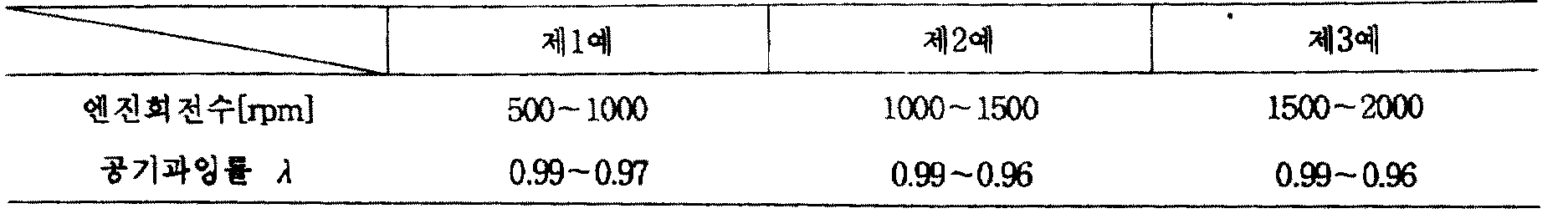
또한, 이 실험의 조건으로는 예를 들면 하기의 제2표에 나타내는 바와 같은 조건의 범위내가 아주 적당하다.Moreover, as conditions of this experiment, the range of conditions as shown to the following 2nd table | surface is very suitable, for example.

[실험예 2]Experimental Example 2
CO의 배출량이 다른 산소센서의를 사용하고, 공연비를 농후한 상태로 설정하고, 전기한 바와 같이 해서 산소센서(36)의 출력신호의 전압을 측정했다.Using the oxygen sensor with different CO emissions, the air-fuel ratio was set to a rich state, and the voltage of the output signal of the
그 실험조건 및 결과는 제3표에 나타낸다.The experimental conditions and results are shown in Table 3.
이 표에 있어서 A, B는 전기한 바와 같지만, C, D의 공연비가 농후(λ=0.97) 한점이 다르다. 또, 시료 No.1-2가 양호한 센서이며, 시료 No.3-4가 CO가 많은 열화된 센서이다.In this table, A and B are as described above, but one point of the air-fuel ratio of C and D is rich (λ = 0.97). Moreover, sample No. 1-2 is a favorable sensor, and sample No. 3-4 is a deteriorated sensor with many CO.

상기 제3표에서 명백한 바와 같이 시료 No.1-2의 양호한 센서에서는 공연비가 농후한 상태에 있어서의 센서의 출력이 크지만 시료 No.3-4의 열화된 센서에서는 센서출력이 적게 되어 있다.As apparent from the above Table 3, the sensor of Sample No. 1-2 has a large output of the sensor in an air-fuel-rich state, but the sensor output of the Sample No. 3-4 deteriorates.
따라서, 소정의 역치(예를 들면 700mv)로 판정을 행하므로서 용이하게 CO의 배출량이 많은 열화된 센서를 검출할 수가 있다.Therefore, by making a determination with a predetermined threshold (for example, 700mv), it is possible to easily detect a deteriorated sensor with a large amount of CO emissions.
또한, 이 실험의 조건으로서는 예를 들면 하기 제4표에 나타나는 것과 같은 조건의 범위내가 아주 적당하다.Moreover, as conditions of this experiment, the range of conditions as shown, for example in the following 4th table | surface is very suitable.
[실험예 3]Experimental Example 3
본 실험예에서는 전기한 실험예와는 달리 공연비를 희박 및 농후한 상태로 주기적으로 전환해서 실험을 행하였다. 결국, 실험예 1-2에서 사용한 것과 같은 양호한 센서나 NOx 혹은 CO의 배출량이 많은 산소센서(36)을 사용해서 산소센서(36)의 출력신호의 전압의 극소치 및 극대치를 측정했다.In the present experimental example, the experiment was performed by periodically switching the air-fuel ratio to a lean and rich state unlike the experimental example described above. As a result, the minimum value and the maximum value of the voltage of the output signal of the
그 실험조건 및 결과를 제5표(NOx의 측정결과) 및 제6표(CO의 측정결과)에 나타낸다.The experimental conditions and results are shown in Table 5 (measurement results of NOx) and Table 6 (measurement results of CO).
여기서, C, D에 있어서의 엔진회전수는 전기한 실험에 1과 같고, 다시 또 양표에 있어서의 공기과잉률(λ) 및 전환 주기(HZ)는 동일하다.Here, the engine speeds in C and D are equal to 1 in the experiments described above, and the excess air ratio? And the switching period HZ in the charts are the same.
또, 양표에 있어서, 시료 No.1-2가 양호한 센서이며, 시료 No.3-5가 열화된 시료이다.In addition, in the table, Sample No. 1-2 is a good sensor, and Sample No. 3-5 is a degraded sample.


이 제5표 및 제6표로부터 명백한 바와 같이 시료 No.1-2의 양호한 센서에서는 공연비가 희박 및 농후한 상태에 있어서의 센서출력의 폭이 크지만 시료 No.3-5의 열화된 센서에서는 센서출력의 폭이 적게되어 있다.As apparent from Tables 5 and 6, in the good sensor of Sample No. 1-2, the sensor output width in the lean and rich air-fuel ratio is large, but in the deteriorated sensor of Sample No. 3-5, The sensor output width is small.
따라서, 소정의 상하 2개의 겨치(예를 들면 낮은 쪽에서 300mv 높은 쪽에서 700mv)로 판정을 행하므로서 용이하게 NOx나 CO의 배출량이 많은 열화된 센서를 함께 검출할 수가 있다. 또한, 이 실험의 조건으로서는 예를 들면 하기하는 제7표에 나타내는 것과 같은 조건의 범위내가 아주 적당하다.Therefore, the determination is made with two predetermined upper and lower wings (for example, 300mv from the lower side and 700mv from the higher side), thereby making it possible to easily detect deteriorated sensors with a large amount of NOx and CO emissions. Moreover, as conditions of this experiment, the range of conditions as shown in the following 7th table | surface is very suitable, for example.

[실험예 4]Experimental Example 4
본 실험예에서는 전기한 실험예와 같이 개방 루우프 제어가 아니고, 공연비의 피이드백 제어를 행한 상태에서 실험을 실시했다.In the present experimental example, the experiment was conducted in the state of performing the feedback control of the air-fuel ratio instead of the open loop control as in the foregoing experimental example.
결국 실험예 1-3에서 사용한 것과 같은 양호한 센서나, NOx 혹은 CO의 배출량의 많은 산소센서의를 사용해서 공연비의 피이드백 제어를 행하고, 산소센서(36)의 출력신호의 전압의 극소치(희박시) 및 극대치(농후시)를 측정했다.Eventually, feedback control of the air-fuel ratio is performed using a good sensor such as that used in Experimental Examples 1-3 or a large amount of NOx or CO emissions, and the minimum value of the voltage of the output signal of the oxygen sensor 36 ) And maximal value (dense).
그 실험조건 및 결과를 제8표(NOx의 측정결과) 및 제9표(CO의 측정결과)에 나타낸다.The experimental conditions and results are shown in Table 8 (measurement results of NOx) and Table 9 (measurement results of CO).
여기서, C, D는 A차량을 이용해서 일정속도 운전을 한때의 실험조건을 나타내고 있다.Here, C and D represent experimental conditions when constant speed operation was carried out using the A vehicle.
또, 양표에 있어서 시료 No.1-2가 양호한 센서이며, 시료 No.3-4가 열화된 센서이다.In addition, sample No. 1-2 is a favorable sensor in the table, and sample No. 3-4 is a deteriorated sensor.


이 제8표, 제9표로부터 명백한 바와 같이 시료 No.1-2의 양호한 센서에서는 공연비가 희박 및 농후한 상태에 있어서의 센서 출력의 폭(극대치와 극소치와의 차)이 크지만 시료 No.3-4의 열화된 센서에서는 센서의 출력의 폭이 적게 되어 있다.As apparent from Tables 8 and 9, in the preferred sensor of Sample No. 1-2, the width of the sensor output (difference between the maximum value and the minimum value) in the lean and rich air-fuel ratio is large. In the 3-4 degraded sensor, the output of the sensor is small.
따라서, 소정의 상하 2개의 역치 V·V(예를 들면 낮은 폭에서 250mv, 높은 쪽에서 850mv)로 판정을 행하므로서 용이하게 NOx나 CO의 배출량이 많은 열화된 센서를 함께 검출할 수가 있다.Therefore, the determination is made with two predetermined upper and lower threshold values V · V (for example, 250 mv at a low width and 850 mv at a high width) to easily detect deteriorated sensors with a large amount of NOx and CO emissions.
또한, 본 발명은 전기한 실시예에 한정되는 일이 없이 본 발명의 범위내에서 각종 형태론 실시할 수 있는 것은 물론이다. 예를 들면, 전기한 실시예에서는 산소센서(36)의 열화를 검출했으나 부산소센서(37)의 열화의 검출에도 적용될 수 있다.It should be understood that the present invention can be embodied in various forms within the scope of the present invention without being limited to the foregoing embodiments. For example, in the above-described embodiment, the degradation of the
(5) 제5실시예의 처리(5) Processing of the fifth embodiment
우선, 제15도의 순서도에 의거해서 공연비를 희박한 일정한 상태로 유지하고, 다시 또는 농후한 일정한 상태로 유지하고, 그때의 산소센서(36)의 출력신호를 측정해서 중앙치를 구하는 처리에 대해 설명한다.First, a process of keeping the air-fuel ratio in a lean constant state again, or in a rich constant state again by measuring the output signal of the
본 처리는 엔진(2)의 온난기가 실시된 상태에서 행해진다. 처음에 공연비의 피이드백 제어를 정지하는 처리를 행한다(단계 100).This process is performed in the state in which the warmth of the
다음에 이 피이드백 제어가 정지된 상태에서 즉 개방 루우프 제어에 의해 연료 분사밸브(25)를 구동 제어해서 공연비를 희박(예를 들면 공기과잉률 λ=1.02)의 상태로 설정하는 처리를 행한다(단계 110).Next, in the state in which the feedback control is stopped, that is, the
그리하여, 이 상태를 소정시간 유지해서 이 희박시의 산소센서(36)의 출력신호 D을 검출한다(단계 120).Thus, this state is maintained for a predetermined time to detect the output signal D of the
다시 또, 개방 루우프 제어에 의해 연료분사밸브(25)를 구동제어해서 공연비를 농후(예를 들면 λ=0.98)의 상태로 설정하는 처리를 행한다(단계 130).Further, the
그리하여, 이 상태를 소정시간 유지해서 이 농후시의 산소센서(36)의 출력신호 D을 검출한다(단계 140).Thus, this state is maintained for a predetermined time to detect the output signal D of the
다음에 산소센서(36)의 희박의 출력신호 D이 소정의 역치 V(예를 들면 400mv) 이상의 경우에는 산소센서(36)이 이상인 것으로 판정하고(단계 150), 첵램프(40)를 점등한다(단계 160).Next, when the lean output signal D of the
또, 산소센서(36)의 농후의 출력신호 D이 소정의 역치 V(예를 들면 700mv) 이하의 경우에는 산소센서의가 이상인 것으로 판정하고(단계 170), 같은 모양으로 첵램프(40)를 점등한다(단계 160).If the rich output signal D of the
그리하여, 전기한 단계 150 혹은 170에서 산소센서(36)이 이상인 것으로 판정된 경우에는 희박의 경우의 출력신호 D및 농후의 경우의 출력신호 D의 중앙치 V를 구하고(단계 180), 그 중앙치 V를 피이드백 제어시에 희박과 농후와를 구분하는 역치(슬라이스 레벨)로서 설정하고(단계 190), 일단 본 처리를 종료한다.Thus, in the case where the
즉, 제16a도에 나타내는 바와 같이 예를 들면 λ=1.02인 때의 출력신호 D의 전압이 500mv, λ=0.98 인대의 출력신호 D의 전압이 900mv의 경우에는 그 중앙치 V는 700mv가 된다.That is, as shown in FIG. 16A, for example, when the voltage of the output signal D when λ = 1.02 is 500mv and the voltage of the output signal D of the λ = 0.98 ligament is 900mv, the median V is 700mv.
따라서, 이 중앙치 V를 피이드백 제어시의 역치로서 채용하면 산소센서(36)의 출력신호가 고전압측 혹은 저전압측에 어긋나서 진동하고 있었다 하더라도 그 진동의 거의 중앙이 역치가 되기 때문에 공연비의 희박이나 농후를 확실히 구분해서 제16도(ℓ)에 나타내는 바와 같이 OV와 5V의 2가지 값의 신호론 변호나 할 수가 있다.Therefore, if the center value V is used as the threshold value for the feedback control, even if the output signal of the
결국 산소센서(36)의 출력신호에 따라서 가장 적당한 역치를 설정할 수 있기 때문에 산소센서(36)이 독의 침입 등에 의해 그 출력이 변동 되었다 해도 공연비의 희박 및 농후한 상태를 확실히 검출해서 아주 적당하게 공연비를 제어할 수가 있다.As a result, the most appropriate threshold value can be set according to the output signal of the
또한, 전기한 제5 실시예에서는 산소센서(36)의 이상을 검출하기 위해 개방루우프 제어에 의해 공연비를 희박 또는 농후한 상태로 변경해서 그 상태를 일정하게 유지하는 제어를 행했으나, 그 이외에도 후술하는 바와 같이, 각종의 이상 검출의 수단을 채용할 수 있다.In the fifth embodiment described above, in order to detect an abnormality of the
예를 들면 개방 루우프 제어에 있어서 공연비를 희박 및 농후한 상태로 소정의 주기로 전환해서 그때의 극소치나 극대치가 소정의 범위내에 없는 경우에 산소센서(36)을 이상으로 판정해도 좋다.For example, in the open loop control, when the air-fuel ratio is switched to a predetermined cycle in a lean and rich state, the
혹은 공연비의 피이드백 제어를 행하고 그때의 출력신호가 소정의 범위내에선 진동하는 경우에 이상이라고 판정해도 좋다.Alternatively, it may be determined that the feedback is abnormal when the air-fuel ratio feedback control is performed and the output signal at that time vibrates within a predetermined range.
또한, 하기에는 다른 실시예의 하드웨어의 구성은 전기한 실시예와 마찬가지이며, 다시 또 다음의 설명에 있어서는 이상판정의 처리의 실명은 간결하게 기술한다.In addition, below, the structure of the hardware of another embodiment is the same as that of the above-mentioned embodiment, In the following description, the real name of the process of abnormality determination is briefly described.
(6) 제6실시예의 처리(6) Processing of the sixth embodiment
다음에 제17도의 순서도에 의해 산소센서(36)의 출력신호의 극소치 및 극대치를 사용해서 공연비를 제어하는 처리에 대해 설명한다.Next, the process of controlling the air-fuel ratio using the minimum value and the maximum value of the output signal of the
우선 전기한 처리와 마찬가지로 공연비의 피이드백 제어를 정지하는 처리를 행한다(단계 200).First, a process of stopping feedback control of the air-fuel ratio is performed in the same manner as in the foregoing process (step 200).
다음에 개방루우프 제어에 의해 연료분사밸브(25)를 구동제어해서 공연비를 농후 및 희박의 상태로 주기적으로 전환하는 처리를 행한다(단계 210).Next, driving control of the
그리하여 그때의 산소센서(36)의 출력신호를 검출해서(단계 220), 그 출력신호의 극소치 및 극대치를 구하는 처리를 행한다(단계 230).Thus, the output signal of the
다음에 산소센서(36)의 출력신호의 극소치 혹은 극대치의 어느쪽인가 한쪽이라도 소정의 출력치의 범위내인 경우에는 산소센서(36)이 이상이라고 판정해서(단계 240), 첵램프(40)를 점등하는 처리를 행한다(단계 250).Next, when either the minimum value or the maximum value of the output signal of the
그리하여, 산소센서의가 이상인 경우에는 전기한 극소치 V및 극대치 V의 중앙치 V를 구한다(단계 260).Thus, when the oxygen sensor is abnormal, the minimum value V and the median value V of the maximum value V are obtained (step 260).
이 중앙치 V를 실제의 피이드백 제어에 있어서의 공연비의 희박과 농후와의 구분하는 역치로서 설치하고(단계 270), 일단 본 처리를 종료한다.This median value V is set as a threshold for distinguishing between lean and rich air-fuel ratio in actual feedback control (step 270), and this process is completed once.
즉, 제18a도에 나타나는 바와 같이 예를 들면 산소센서(36)의 출력신호가 미리 설정한 역치 V보다 큰 전압으로 진동하는 경우에는 산소센서(36)이 이상이 있다고 판단해서 출력신호의 극소치 V및 극대치 V의 중앙치 V를 구하여, 이 중앙치 V를 역치로서 채용한다.That is, as shown in FIG. 18A, for example, when the output signal of the
그것에 의해 산소센서(36)의 출력신호가 이상이라도 실제의 공연비 피이드백 제어시에는 확실히 공연비의 희박 또는 농후의 상태를 구별해서 제18도(ℓ)에 나타나는 바와 같이 OV와 5V의 2개의 값이 신호로 변환할 수가 있다.As a result, even when the output signal of the
이와 같이 본 실시예에서는 산소센서(36)의 출력신호에 따라서 역치를 변경할 수 있기 때문에 산소센서(36)에 독이 침입해서 그 출력이 고전압축 혹은 저전압축으로 변동했다고 해도 공연비를 아주 적당하게 제어할 수가 있다.Thus, in this embodiment, the threshold value can be changed according to the output signal of the
(7) 제7실시예의 처리(7) Processing of the seventh embodiment
다음에 제19도의 순서도에 의거해서 산소센서(36)의 출력신호의 중앙치 V를 사용한 다른 처리에 대해 설명한다. 우선, 전기한 제5 실시예 혹은 제6 실시예와 마찬가지로 해서 산소센서(36)의 이상을 검출한 경우에는(단계 300), 산소센서(36)의 출력신호로부터 중앙치 V를 구하는 처리를 행한다(단계 310).Next, another process using the median value V of the output signal of the
그리하여, 이 중앙치 V에 의거하여 실제의 피이드백 제어시에 산소센서(36)으로부터 출력되는 신호의 전압을 비례 배분해서 진폭이 큰 정상적인 신호로 변경하는 처리를 행한다(단계 320).Thus, on the basis of the median value V, a process of proportionally distributing the voltage of the signal output from the
일단 본 처리를 종료한다.This process ends once.
즉, 제20도 및 하기하는 제10표에 나타내는 바와 같이 산소센서(36)의 출력신호의 전압을 변환한다.That is, as shown in FIG. 20 and the following Table 10, the voltage of the output signal of the

예를 들면 미리 설정된 역치 Vo보다 출력신호의 전압이 높은 경우에는 공연비의 희박(λ=1.02)에 있어서의 500mv의 신호를 OV로, 또 농후(λ=0.98)에 있어서의 900mv의 신호를 1V라는 식으로 변환한다.For example, when the voltage of the output signal is higher than the preset threshold Vo, the signal of 500mv at lean (λ = 1.02) of air-fuel ratio is OV, and the signal of 900mv at rich (λ = 0.98) is 1V. Convert to an expression.
결국 산소센서(36)의 이상한 출력신호의 진폭의 중심을 미리 설정된 역치 Vo의 500mv로 보정함과 아울러 출력신호를 큰 진폭의 신호가 되도록 비례배분하여 변환시키는 처리를 행한다.As a result, a process of correcting the center of the amplitude of the abnormal output signal of the
또한, 본 실시예에서는 산소센서(36)의 출력신호의 측정치를 X로 하고 변환치를 Y로 하면 하기하는 변환식에 의거해서 변환한다.In addition, in this embodiment, when the measured value of the output signal of the
Y=2.5×-1250Y = 2.5 × -1250
따라서, 이와 같은 처리에 의해 신호가 보정되기 때문에 산소센서(36)의 출력신호가 고전압측이나 저전압측에 기울어져 있거나 혹은 진폭이 적은 것이라도 미리 설정된 역치 Vo를 사용하여 공연비의 상태를 확실하게 검출할 수 있고, 그것에 의해 아주 적당하게 공연비의 피이드백 제어를 행할 수가 있다. 또한, 본 발명은 전기한 실시예에 한정되는 일 없이 본 발명의 범위내에서 각종 형태로 실시할 수 있는 것은 물론이다. 전기한 바와 같이 청구항(1)의 산소센서의 이상 검출장치는 개방 루우프 제어에 의해 공연비가 희박하게 설정된 때에 산소센서의 출력신호가 소정의 역치 이상의 경우 혹은 공연비가 농후하게 설정된 때에 산소센서의 출력신호가 소정의 역치 이하의 경우에는 산소센서에 이상이 있다고 판정하기 때문에 실리콘 혹은 납에 의해 독이 침입되어 공연비의 피이드 백 제어에 사용하면 NOx 혹은 CO가 증가하는 열화된 산소센서를 용이하고 또한 확실하게 검출할 수가 있다. 또, 청구항(2)의 산소센서의 이상검출장치는 개방루우프 제어에 의해서 공연비가 희박 및 농후로 설정된 때의 산소센서의 출력신호의 극소치 및 극대치를 검출하고, 극소치 혹은 극대치의 적어도 한쪽의 소정의 출력치의 범위내인 경우에는 산소센서에 이상이 있다고 판정하기 때문에 전기한 바와 마찬가지로 열화된 산소센서를 용이하게 또한 확실하게 검출할 수가 있다.Therefore, since the signal is corrected by such a process, even if the output signal of the
다시 또, 청구항(3)의 산소센서의 이상 검출장치는 공연비의 피이드백 제어를 행하고 그때의 산소센서의 출력신호가 소정의 출력치의 범위내에 있는 경우에는 산소센서에 이상이 있다고 판정하기 때문에 전기한 바와 마찬가지로 여로하된 산소센서를 용이하게 또한 확실하게 검출할 수가 있다.Again, the oxygen sensor abnormality detecting apparatus of claim (3) performs feedback control of the air-fuel ratio, and when the output signal of the oxygen sensor at that time is within a predetermined output value range, it is determined that the oxygen sensor is abnormal. Similarly, the filtered oxygen sensor can be detected easily and reliably.
이상 설명한 바와 같이 본 발명의 공연비 제어장치는 개방 루우프 제어에 의해 공연비를 희박이나 농후의 상태로 설정하고, 그 때의 산소센서(36)의 출력신호로부터 출력신호의 중앙치를 구하는 것이며, 산소센서(36)의 이상이 검출된 경우에는 이 중앙치를 피이드백 제어시의 공연비의 희박과 농후와는 구분하는 역치로서 설정하기 때문에 산소센서가 독의 침입 등에 열화해서 이상의 신호가 출력된 경우라도 공연비의 피이드백 제어를 아주 적당하게 행할 수가 있다.As described above, the air-fuel ratio control apparatus of the present invention sets the air-fuel ratio to a lean or rich state by open loop control, and obtains the median value of the output signal from the output signal of the
Claims (4)
Applications Claiming Priority (6)
| Application Number | Priority Date | Filing Date | Title |
|---|---|---|---|
| JP1-155230 | 1989-06-16 | ||
| JP155229/1989 | 1989-06-16 | ||
| JP1155229A JP2837690B2 (en) | 1989-06-16 | 1989-06-16 | Oxygen sensor abnormality detection device |
| JP1-155229 | 1989-06-16 | ||
| JP155230/1989 | 1989-06-16 | ||
| JP15523089A JP2683418B2 (en) | 1989-06-16 | 1989-06-16 | Air-fuel ratio control device |
Publications (2)
| Publication Number | Publication Date |
|---|---|
| KR910001231A KR910001231A (en) | 1991-01-30 |
| KR970010317B1 true KR970010317B1 (en) | 1997-06-25 |
Family
ID=26483290
Family Applications (1)
| Application Number | Title | Priority Date | Filing Date |
|---|---|---|---|
| KR1019900008799A KR970010317B1 (en) | 1989-06-16 | 1990-06-15 | Apparatus for detecting abnormality of oxygen sensor and controlling air/fuel ratio |
Country Status (4)
| Country | Link |
|---|---|
| US (1) | US5020499A (en) |
| EP (2) | EP0549566B1 (en) |
| KR (1) | KR970010317B1 (en) |
| DE (2) | DE69003459T2 (en) |
Families Citing this family (42)
| Publication number | Priority date | Publication date | Assignee | Title |
|---|---|---|---|---|
| DE3835285A1 (en) * | 1988-10-15 | 1990-04-19 | Bosch Gmbh Robert | METHOD AND DEVICE FOR DETECTING THE IGNITION |
| JP2832049B2 (en) * | 1989-12-08 | 1998-12-02 | マツダ株式会社 | Engine air-fuel ratio control device |
| DE4122828C2 (en) * | 1990-07-10 | 1996-07-25 | Mitsubishi Motors Corp | Air-fuel ratio control device for an internal combustion engine in a motor vehicle |
| JP2755500B2 (en) * | 1991-04-15 | 1998-05-20 | 三菱電機株式会社 | Engine abnormality detection device |
| US5305727A (en) * | 1992-06-01 | 1994-04-26 | Ford Motor Company | Oxygen sensor monitoring |
| US5357791A (en) * | 1993-03-15 | 1994-10-25 | Ford Motor Company | OBD-II exhaust gas oxygen sensor |
| DE4308570C2 (en) * | 1993-03-18 | 1994-06-30 | Bayerische Motoren Werke Ag | Disturbance air valve for an internal combustion engine |
| US5325711A (en) * | 1993-07-06 | 1994-07-05 | Ford Motor Company | Air-fuel modulation for oxygen sensor monitoring |
| DE4332711A1 (en) * | 1993-09-25 | 1995-03-30 | Bosch Gmbh Robert | Device for fault detection in a device for knock detection |
| US5392643A (en) * | 1993-11-22 | 1995-02-28 | Chrysler Corporation | Oxygen heater sensor diagnostic routine |
| US5392599A (en) * | 1994-01-10 | 1995-02-28 | Ford Motor Company | Engine air/fuel control with adaptive correction of ego sensor output |
| GB9402018D0 (en) * | 1994-02-02 | 1994-03-30 | British Gas Plc | Apparatus for detecting faults in a combustion sensor |
| JPH08121220A (en) * | 1994-10-21 | 1996-05-14 | Sanshin Ind Co Ltd | Combustion control device for engine |
| DE19612212B4 (en) * | 1995-03-31 | 2005-12-08 | Denso Corp., Kariya | Diagnostic device for an air / fuel ratio sensor |
| US5522250A (en) * | 1995-04-06 | 1996-06-04 | Ford Motor Company | Aged exhaust gas oxygen sensor simulator |
| DE19646008B4 (en) * | 1995-11-08 | 2005-03-17 | Denso Corp., Kariya | Abnormality detecting device for an air-fuel ratio control system |
| JP3156604B2 (en) * | 1996-02-28 | 2001-04-16 | トヨタ自動車株式会社 | Air-fuel ratio control device for internal combustion engine |
| IT1285311B1 (en) * | 1996-03-12 | 1998-06-03 | Magneti Marelli Spa | METHOD OF DIAGNOSING THE EFFICIENCY OF AN EXHAUST GAS STOICHIOMETRIC COMPOSITION SENSOR PLACED DOWNSTREAM OF A CONVERTER |
| DE19725567B4 (en) * | 1996-06-18 | 2006-01-26 | Denso Corp., Kariya | Fault diagnosis system for an air / fuel ratio control system |
| FR2756389B1 (en) * | 1996-11-22 | 1999-01-22 | Renault | METHOD FOR CONTROLLING A SENSOR EQUIPPED WITH AN INTERNAL COMBUSTION ENGINE |
| JP3657776B2 (en) * | 1998-06-03 | 2005-06-08 | 株式会社ケーヒン | Oxygen concentration sensor abnormality determination device |
| DE19838334B4 (en) * | 1998-08-24 | 2012-03-15 | Robert Bosch Gmbh | Diagnostic device for a potentiometric, electrically heated exhaust gas probe for controlling combustion processes |
| DE19844994C2 (en) * | 1998-09-30 | 2002-01-17 | Siemens Ag | Method for diagnosing a continuous lambda probe |
| JP3744761B2 (en) * | 2000-02-08 | 2006-02-15 | 株式会社日立製作所 | Correction device for air-fuel ratio detection device |
| US6810659B1 (en) * | 2000-03-17 | 2004-11-02 | Ford Global Technologies, Llc | Method for determining emission control system operability |
| JP3540989B2 (en) * | 2000-04-10 | 2004-07-07 | 本田技研工業株式会社 | Exhaust gas purification device for internal combustion engine |
| JP3755646B2 (en) * | 2001-05-22 | 2006-03-15 | 三菱電機株式会社 | O2 sensor failure diagnosis apparatus and method |
| KR100435707B1 (en) * | 2002-05-31 | 2004-06-12 | 현대자동차주식회사 | Method of checking rear o2 sensor trouble for vehicles |
| US20040010524A1 (en) * | 2002-07-12 | 2004-01-15 | Wallace Michael W. | Efficient method and system for delivering resources in broadcast environment |
| JP4194085B2 (en) * | 2003-03-18 | 2008-12-10 | フィガロ技研株式会社 | Self-diagnosis method and gas detector for proton conductor gas sensor |
| JP4094538B2 (en) * | 2003-12-11 | 2008-06-04 | 三菱電機株式会社 | Air-fuel ratio sensor failure diagnosis device |
| US7142976B2 (en) * | 2004-06-29 | 2006-11-28 | Ngk Spark Plug Co., Ltd. | Abnormality diagnosis method and apparatus for gas concentration measuring device |
| JP4375236B2 (en) * | 2005-01-19 | 2009-12-02 | トヨタ自動車株式会社 | Exhaust gas sensor deterioration detection device |
| US7255098B1 (en) | 2006-04-27 | 2007-08-14 | Caterpillar Inc. | Engine emissions control system |
| DE102006047188B4 (en) * | 2006-10-05 | 2009-09-03 | Continental Automotive Gmbh | Method and device for monitoring an exhaust gas probe |
| EP1961940B1 (en) * | 2007-02-21 | 2019-04-03 | NGK Spark Plug Co., Ltd. | Diagnostic method and control apparatus for gas sensor |
| JP4697201B2 (en) | 2007-07-19 | 2011-06-08 | トヨタ自動車株式会社 | Abnormality detection device for internal combustion engine |
| JP2009036023A (en) * | 2007-07-31 | 2009-02-19 | Denso Corp | Different fuel mixing determination device of internal combustion engine |
| JP2011163229A (en) * | 2010-02-10 | 2011-08-25 | Toyota Motor Corp | Device for determining air-fuel ratio imbalance between cylinders of multi-cylinder internal combustion engine |
| DE102011083775B4 (en) * | 2011-09-29 | 2013-12-05 | Continental Automotive Gmbh | Method and device for operating an internal combustion engine |
| FR3056254B1 (en) * | 2016-09-16 | 2018-10-12 | Renault Sas | METHOD FOR DIAGNOSING A PROPORTIONAL OXYGEN PROBE ARRANGED AHEAD OF THE POST-PROCESSING SYSTEM OF AN INTERNAL COMBUSTION ENGINE WITH CONTROLLED IGNITION. |
| CN114704362A (en) * | 2021-04-26 | 2022-07-05 | 长城汽车股份有限公司 | Lean-burn NOx trap fault detection method, device, vehicle, medium and equipment |
Family Cites Families (14)
| Publication number | Priority date | Publication date | Assignee | Title |
|---|---|---|---|---|
| US3938075A (en) * | 1974-09-30 | 1976-02-10 | The Bendix Corporation | Exhaust gas sensor failure detection system |
| JPS5297027A (en) * | 1976-02-09 | 1977-08-15 | Nissan Motor Co Ltd | Air fuel ratio controller |
| JPS5395421A (en) * | 1977-01-29 | 1978-08-21 | Toyota Motor Corp | Exhaust gas purifier for internal combustion engine |
| JPS5762944A (en) * | 1980-09-02 | 1982-04-16 | Honda Motor Co Ltd | Fail-saft device for sensors for detecting states and conditions of internal combustion engine |
| JPS5865948A (en) * | 1981-10-12 | 1983-04-19 | Daihatsu Motor Co Ltd | Indicator of air-fuel ratio control in internal- combustion engine |
| JPS58222939A (en) * | 1982-05-28 | 1983-12-24 | Honda Motor Co Ltd | Method of controlling air fuel ratio of internal combustion engine in trouble of oxygen concentration detecting system |
| JPS593137A (en) * | 1982-06-29 | 1984-01-09 | Honda Motor Co Ltd | Air-fuel ratio feedback-control when exhaust concentration detection system is damaged in internal-combustion engine |
| DE3311131A1 (en) * | 1983-03-26 | 1984-09-27 | Robert Bosch Gmbh, 7000 Stuttgart | Method of checking the serviceability of an oxygen probe, and device for carrying out the method |
| JPS6131639A (en) * | 1984-07-20 | 1986-02-14 | Fuji Heavy Ind Ltd | Air-fuel ratio control for car engine |
| JPS6181541A (en) * | 1984-09-19 | 1986-04-25 | Honda Motor Co Ltd | Method of detecting trouble on exhaust gas concentration detecting system of internal-combustion engine |
| JPS6293644A (en) * | 1985-10-21 | 1987-04-30 | Honda Motor Co Ltd | Method for judging characteristic of exhaust gas concentration detector |
| JP2564510B2 (en) * | 1985-12-25 | 1996-12-18 | 本田技研工業株式会社 | Abnormality detection method for exhaust gas concentration sensor of internal combustion engine |
| JPH0713600B2 (en) * | 1986-12-29 | 1995-02-15 | 日本特殊陶業株式会社 | Oxygen sensor evaluation device |
| JPS648334A (en) * | 1987-06-30 | 1989-01-12 | Mazda Motor | Air-fuel ratio controller of engine |
-
1990
- 1990-06-15 KR KR1019900008799A patent/KR970010317B1/en not_active IP Right Cessation
- 1990-06-18 EP EP93102610A patent/EP0549566B1/en not_active Expired - Lifetime
- 1990-06-18 DE DE90111417T patent/DE69003459T2/en not_active Expired - Fee Related
- 1990-06-18 DE DE69028216T patent/DE69028216T2/en not_active Expired - Fee Related
- 1990-06-18 EP EP90111417A patent/EP0402953B1/en not_active Expired - Lifetime
- 1990-06-18 US US07/539,119 patent/US5020499A/en not_active Expired - Lifetime
Also Published As
| Publication number | Publication date |
|---|---|
| EP0402953A2 (en) | 1990-12-19 |
| EP0549566A2 (en) | 1993-06-30 |
| DE69003459T2 (en) | 1994-05-11 |
| EP0402953B1 (en) | 1993-09-22 |
| DE69003459D1 (en) | 1993-10-28 |
| KR910001231A (en) | 1991-01-30 |
| US5020499A (en) | 1991-06-04 |
| EP0549566A3 (en) | 1994-06-22 |
| EP0549566B1 (en) | 1996-08-21 |
| DE69028216T2 (en) | 1997-01-09 |
| DE69028216D1 (en) | 1996-09-26 |
| EP0402953A3 (en) | 1991-03-20 |
Similar Documents
| Publication | Publication Date | Title |
|---|---|---|
| KR970010317B1 (en) | Apparatus for detecting abnormality of oxygen sensor and controlling air/fuel ratio | |
| US5533332A (en) | Method and apparatus for self diagnosis of an internal combustion engine | |
| US5235957A (en) | Diagnosing device and diagnosing method in air/fuel ratio control device for internal combustion engine | |
| JP2893308B2 (en) | Air-fuel ratio control device for internal combustion engine | |
| EP0136519A2 (en) | Air-fuel ratio control apparatus for internal combustion engines | |
| EP0423792B1 (en) | Air/fuel ratio feedback control system for internal combustion engine | |
| US6470674B1 (en) | Deterioration detecting apparatus and method for engine exhaust gas purifying device | |
| JPH08338286A (en) | Exhaust system failure diagnostic device for internal combustion engine | |
| EP0292175A2 (en) | Air/Fuel ratio control system for internal combustion engine | |
| US5172676A (en) | Air-fuel ratio control apparatus in internal combustion engine using different kinds of fuels | |
| US4617901A (en) | Air-fuel ratio feedback control method for internal combustion engines | |
| US6176080B1 (en) | Oxygen concentration sensor abnormality-detecting system for internal combustion engines | |
| JP2547380B2 (en) | Air-fuel ratio feedback control method for internal combustion engine | |
| JP2737482B2 (en) | Degradation diagnosis device for catalytic converter device in internal combustion engine | |
| JP2837690B2 (en) | Oxygen sensor abnormality detection device | |
| JP2683418B2 (en) | Air-fuel ratio control device | |
| JP4385542B2 (en) | Air-fuel ratio control device for internal combustion engine | |
| JPS62119450A (en) | Decision on characteristic of exhaust density detector | |
| JPH077562Y2 (en) | Electronically controlled fuel injection device for internal combustion engine | |
| JPH08303234A (en) | Device for diagnosing catalyst deterioration in internal combustion engine | |
| JPS62139943A (en) | Air-fuel ratio control method for internal combustion engine | |
| JPS62162955A (en) | Method for discriminating activation of detector for concentration of exhaust gas component of engine | |
| JPS62255552A (en) | Air-fuel ratio feedback control method for internal combustion engine | |
| JPH08101161A (en) | Judging device for deterioration of air-fuel ratio sensor of internal combustion engine | |
| JPH0830437B2 (en) | Fail-safe device for air-fuel ratio controller of internal combustion engine |
Legal Events
| Date | Code | Title | Description |
|---|---|---|---|
| A201 | Request for examination | ||
| G160 | Decision to publish patent application | ||
| E701 | Decision to grant or registration of patent right | ||
| GRNT | Written decision to grant | ||
| FPAY | Annual fee payment |
Payment date: 20040823 Year of fee payment: 8 |
|
| LAPS | Lapse due to unpaid annual fee |