KR970005639B1 - Light beam deflection devices - Google Patents
Light beam deflection devices Download PDFInfo
- Publication number
- KR970005639B1 KR970005639B1 KR1019880008332A KR880008332A KR970005639B1 KR 970005639 B1 KR970005639 B1 KR 970005639B1 KR 1019880008332 A KR1019880008332 A KR 1019880008332A KR 880008332 A KR880008332 A KR 880008332A KR 970005639 B1 KR970005639 B1 KR 970005639B1
- Authority
- KR
- South Korea
- Prior art keywords
- light beam
- piezoelectric crystal
- planar surface
- deflection
- lens element
- Prior art date
Links
Images


Classifications
-
- G—PHYSICS
- G02—OPTICS
- G02F—OPTICAL DEVICES OR ARRANGEMENTS FOR THE CONTROL OF LIGHT BY MODIFICATION OF THE OPTICAL PROPERTIES OF THE MEDIA OF THE ELEMENTS INVOLVED THEREIN; NON-LINEAR OPTICS; FREQUENCY-CHANGING OF LIGHT; OPTICAL LOGIC ELEMENTS; OPTICAL ANALOGUE/DIGITAL CONVERTERS
- G02F1/00—Devices or arrangements for the control of the intensity, colour, phase, polarisation or direction of light arriving from an independent light source, e.g. switching, gating or modulating; Non-linear optics
- G02F1/29—Devices or arrangements for the control of the intensity, colour, phase, polarisation or direction of light arriving from an independent light source, e.g. switching, gating or modulating; Non-linear optics for the control of the position or the direction of light beams, i.e. deflection
- G02F1/33—Acousto-optical deflection devices
-
- G—PHYSICS
- G11—INFORMATION STORAGE
- G11B—INFORMATION STORAGE BASED ON RELATIVE MOVEMENT BETWEEN RECORD CARRIER AND TRANSDUCER
- G11B7/00—Recording or reproducing by optical means, e.g. recording using a thermal beam of optical radiation by modifying optical properties or the physical structure, reproducing using an optical beam at lower power by sensing optical properties; Record carriers therefor
- G11B7/12—Heads, e.g. forming of the optical beam spot or modulation of the optical beam
- G11B7/135—Means for guiding the beam from the source to the record carrier or from the record carrier to the detector
- G11B7/1365—Separate or integrated refractive elements, e.g. wave plates
- G11B7/1369—Active plates, e.g. liquid crystal panels or electrostrictive elements
-
- G—PHYSICS
- G02—OPTICS
- G02F—OPTICAL DEVICES OR ARRANGEMENTS FOR THE CONTROL OF LIGHT BY MODIFICATION OF THE OPTICAL PROPERTIES OF THE MEDIA OF THE ELEMENTS INVOLVED THEREIN; NON-LINEAR OPTICS; FREQUENCY-CHANGING OF LIGHT; OPTICAL LOGIC ELEMENTS; OPTICAL ANALOGUE/DIGITAL CONVERTERS
- G02F1/00—Devices or arrangements for the control of the intensity, colour, phase, polarisation or direction of light arriving from an independent light source, e.g. switching, gating or modulating; Non-linear optics
- G02F1/29—Devices or arrangements for the control of the intensity, colour, phase, polarisation or direction of light arriving from an independent light source, e.g. switching, gating or modulating; Non-linear optics for the control of the position or the direction of light beams, i.e. deflection
- G02F1/33—Acousto-optical deflection devices
- G02F1/335—Acousto-optical deflection devices having an optical waveguide structure
Landscapes
- Physics & Mathematics (AREA)
- Nonlinear Science (AREA)
- Optics & Photonics (AREA)
- General Physics & Mathematics (AREA)
- Chemical & Material Sciences (AREA)
- Crystallography & Structural Chemistry (AREA)
- Optical Head (AREA)
- Optical Modulation, Optical Deflection, Nonlinear Optics, Optical Demodulation, Optical Logic Elements (AREA)
- Particle Accelerators (AREA)
- Warping, Beaming, Or Leasing (AREA)
- Optical Recording Or Reproduction (AREA)
- Optical Radar Systems And Details Thereof (AREA)
Abstract
Description
제1도는 이전에 제의한 음향 광학 편향기를 나타내는 개략적 예증도.1 is a schematic illustration showing the previously proposed acoustooptic deflector.
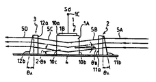
제2도는 본 발명에 따른 광선빔 편향의 한 실시예를 보이는 개략적 평면도.2 is a schematic plan view showing one embodiment of light beam deflection according to the present invention.
제3도는 본 발명에 따른 광선빔 편향 장치의 한 실시예를 보이는 개략적 측면도.3 is a schematic side view showing one embodiment of a light beam deflection apparatus according to the present invention.
제4도는 제2도 및 제3도에서 보인 실시예의 동작을 설명하기 위해 사용한 개략적 예증도.4 is a schematic illustration used to explain the operation of the embodiment shown in FIGS. 2 and 3;
제5도는 적용된 제2 및 제3도에서 보인 실시예에 대한 광학 디스크 기록 시스템의 한 예를 보이는 개략적 예증도.FIG. 5 is a schematic illustration showing an example of an optical disc recording system for the embodiment shown in FIGS. 2 and 3 applied. FIG.
* 도면의 주요부분에 대한 부호의 설명* Explanation of symbols for main parts of the drawings
1 : 광선빔 편향장치 31,35,38 : 거울1:
33 : 음향광학변조기 40 : 광학 기록 디스크33: acoustic optical modulator 40: optical recording disc
32,34,37 : 볼록 렌즈 30 : 레이저 광선원32, 34, 37: convex lens 30: laser light source
본 발명은 보편적 광선빔 편향장치에 관한 것으로, 특히, 음향 광학 소자에 투사되는 광선을 편향하기 위해 음향 광학 소자를 사용하는 개량된 광선빔 편향 장치에 관한 것이다.TECHNICAL FIELD The present invention relates to a universal light beam deflector, and more particularly, to an improved light beam deflector using an acoustooptical device for deflecting light beams projected onto the acoustooptic device.
그것들은 많은 형태의 소위 광학 디스크로 제의되어 왔었고, 광학 기록 디스크의 각각은 입사되는 광선빔에 의해 정보 신호를 기록 및 정보 신호를 판독하는데 유용하다. 상기 광학 기록 디스크의 한 형태는 동일 제작 과정에서 광학 기록 디스크와 충돌하므로 야기된 기록에 대하여 광선빔에 의해 기록된 워블링 피트의 대다수로 제공된다. 상기 워블링 피트는 제작 과정후에 정보로부터 기록 또는 판독을 위해 광학 기록 디스크와 충돌하는 광선빔의 추적 서어브 조절을 위해 사용된다.They have been proposed in many forms of so-called optical discs, and each of the optical recording discs is useful for recording the information signal and reading the information signal by the incident light beam. One type of optical recording disc is provided with the majority of wobbling pits recorded by the light beam for the recording caused by collision with the optical recording disc in the same production process. The wobbling pit is used for adjusting the tracking sub of the beam of light that collides with the optical recording disc for recording or reading from information after the manufacturing process.
광학 기록 디스크상의 워블링 피트를 기록하기 위해, 그것은 각 워블링 피트로 동기되어 예정된 각에서 기록을 위해 광선빔 편향이 요구된다. 상기 경우에 있어서의 음향 광학 변향기는 기록을 위해 광선빔을 편향하는데 사용되고, 기록을 위한 광선빔은 방정식 : 2.d.sinθ=nλ로 표현된 안정화하는 브래그 조건 및 음향 광학 편향기내의 격자면과의 관계로 정의된 시사각에서 음향 광학 편향기에 입사되도록 야기되어야만 하고, 방정식에서 d는 격자면의 간격을 나타내고,λ는 음향광학 변환기에 입사되는 기록을 위한 광선빔의 파장을 나타내고, n은 정수를 나타낸다. (상기 시사각 θ는 브래그각이라고도 한다) 따라서, 기록용 광선빔이 일직선 광로를 따라 음향 광학 편향기로 입사되도록 음향 광학 편향기가 위치되었을 때, 기록용 광선빔은, 기록용 광선빔이 음향 광학 편향기로 입사되는 일직선 통로와 2.θ의 각도로 연장된 또 다른 일직선 광로를 따라 음향 광학 편향기로부터 방사된다.In order to record the wobbling pit on the optical recording disc, it is required to have a beam beam deflection for recording at a predetermined angle in synchronization with each wobbling pit. In this case, the acoustooptic deflector is used to deflect the beam of light for recording, and the beam of light for recording is the stabilizing Bragg condition represented by the equation: 2.d.sin? Should be caused to be incident on the acousto-optical deflector at the viewing angle defined in relation to, in which d represents the spacing of the grating plane, λ represents the wavelength of the light beam for recording incident on the acoustooptic transducer, and n is Represents an integer. (The angle of view θ is also referred to as Bragg angle.) Therefore, when the acoustooptic deflector is positioned so that the recording light beam is incident to the acoustooptic deflector along a straight optical path, the recording light beam is acoustic optical deflection. Radiated from the acoustooptic deflector along a straight path entering the plane and another straight light path extending at an angle of 2.θ.
제1도는 상기에서 설명한 방법과 같이 음향 광학 편향기에 의해 야기된 광선빔 편향의 상태를 보인다. 제1도에서, 음향 광학 편향기를 형성하는 음향 광학 소자(20)는 수정으로된 압전성 결정 베이스(20A), 텔루이움 이산화물(TeO2)또는 그와 유사한 그리고 압전성 결정 베이스(20A)에 부착된 변환기(20B)를 구비한다. 베이스(20B)는, 예를 들면, 공급되어지는 200∼300㎒의 주파수를 가지고 있는 신호(Ss)에서 신호 입력 단자(20C)에 접속된다. 신호(Ss)가 신호 입력 단자(20C)에서 공급되었을 때, 회절격자(23)는 동시에 발생하는 초음속파에 의해 압전성 결정 베이스 내에 형성된다. 이런 상태하의 회절 격자(23)는 압전성 결정 베이스(20)내에 형성되고, 입사되는 광선빔은 입사면(20i)으로부터 압전성 결정 베이스(20A)을 향하여 입사하고, 그것은 회절격자의 각 격자면에 수직을 이루며, 브래그 조건을 안정화하는 입사각(θ)에서는, 압전성 결정 베이스(20A)의 외향면(20O)으로부터 방사되도록 압전성 결정 베이스(20A)내에 형성되는 회절격자에 의해 편향되고, 입사광 빔(21)과 2θ의 각을 향하도록 된 의향 광선빔(22)처럼, 그것은 회절격자(23)의 각 격자면에 수직한다.Figure 1 shows the state of light beam deflection caused by the acoustooptic deflector as in the method described above. In FIG. 1, the acousto-
상기에서 설명한 것 같이, 상기 경우에 있어서의 음향 광학 변환기는 제1도에서 보여진 압전성 결정 베이스(20A)와 같이 몸체부로 공급된 음향 광학 소자로 구성되고, 입사 광선빔은 입사광을 안정화하는 브래그 조건에서 정확하게 입사면으로부터 음향 광학 소자에 입사되도록 요구되며, 편향의 결과, 의향 광선빔은 입사광선 빔과 입사각의 두배로 대응하는 각이 되도록 하는 음향 광학 소자의 외향면으로부터 방사한다. 결과적으로, 그것은 음향 광학 소자 및 입사광로 그리고 외향 광선빔을 정확하고 정밀하게 배열하기는 매우 어렵다.As described above, the acoustooptic transducer in this case consists of an acoustooptic element supplied to the body, such as the
더우기, 변환기는 음향 광학 소자로 제공되고, 제1도에서 보인것과 같은 변환기(20B)는, 음향 광학 소자내의 회절격자에서 입사 광선빔의 단면까지 거의 면적이 같도록 설계하는 관점에서 가끔 크기가 제한된다. 이것은 외향 광선빔의 단면이 타원형으로 변형되는 것을 단점으로 하고, 그리고 이 경우에 있어서의 외향 광선빔은 광학 기록 디스크 상의 워블링 피트들을 기록하기 위해 사용된 타원형의 변형된 단면을 가지고 그것들은 워블링 피트의 각각이 올바른 모양으로 제공되지 않는다는 문제를 야기시킨다.Moreover, the transducer is provided as an acousto-optic element, and the
따라서, 광선빔 편향장치가 제공하는 본 발명의 목적은 음향 광학 소자에 투사되는 광선빔을 편향하기 위해 음향 광학 소자를 사용하고, 진술한 문제 및 종래 기술에서 부딪힌 단점들을 피하는 것이다.Accordingly, it is an object of the present invention provided by a light beam deflecting device to use an acoustooptical device for deflecting a light beam projected onto the acoustooptical device, and to avoid the problems mentioned and the disadvantages encountered in the prior art.
본 발명의 또 다른 목적은 음향 광학 소자에 투사되는 광선빔을 편향하기 위해 음향 광학 소자를 사용하는 광선빔 편향장치를 제공하는 것으로 광학 소자 및 투사되는 광선빔의 광학통로 그리고 음향소자로부터 방사하는 것에 있어서는 적당한 배열로 쉽게 배치될 수 있다는 것이다.It is still another object of the present invention to provide a light beam deflecting device that uses an acoustooptical device for deflecting a light beam projected onto the acoustooptical device, and to radiate from the optical path and the optical path of the projected light beam and from the acoustic device. In this case, it can be easily arranged in a suitable arrangement.
더우기 본 발명의 목적은 음향 광학 소자에 투사되는 광선빔을 편향하기 위해 음향 광학 소자를 사용하는 광선빔 편향 장치를 제공하는 것으로, 단면에서 변형을 제거하여 편향하는 것이다.Furthermore, it is an object of the present invention to provide a light beam deflection apparatus using an acoustooptical device for deflecting a light beam projected onto the acoustooptical device, which deflects the deflection by removing the deformation from the cross section.
더욱 본 발명의 목적은 음향 광학 소자에 투사되는 광선빔을 편향하기 위해 음향 광학 소자를 사용하는 광선빔 편향 장치를 제공하는 것으로, 그것은 광학 기록 디스크 상에 워블링 피트를 기록하기 위한 시스템을 사용하기에 적합하다는 것이다.It is further an object of the present invention to provide a light beam deflection apparatus using an acoustooptical device for deflecting a light beam projected onto the acoustooptical device, which uses a system for recording a wobbling pit on an optical recording disc. Is suitable for.
본 발명에 따라, 그것들은 제1평면 표면에 각각 수직을 이루고 그리고 서로 마주한 제1평면 표면 및 제2 그리고 제2평면 표면을 가지고 있고 그리고 편향 제어신호로 공급되고 그리고 압전성 결정 베이스의 제1평면 표면에 부착된 변환기를 가지는 압전성 결정 베이스를 포함하는 음향 광학 소자와, 그리고 편향 제어 신호에 응답하는 제1평면 표면에 실제적으로 수직을 이루는 편향면내의 제2평면에서 제3평면 표면까지 압정성 결정 베이스를 통해 통과하는 광선빔을 효과적으로 편향하는 음향 광학 소자를 구비하는 광선빔 편향장치로 구비되며, 제1렌즈 소자는 원통 렌즈를 형성하는 제1원통 표면 및 제1원통 표면에 마주한 제1경사진 평면 표면과 편향면에 실제로 수직을 이루는 방향을 따라 연장되는 곡선을 갖는 압전성 결정 베이스의 제2평면 표면을 향해 위치된 제1원통 표면과 제1경사진 평면 표면에서 제1원통 표면까지 제1렌즈 소자를 통해 통과하는 압전성 결정 베이스의 제24평면 표면에 투사되는 광선빔을 위한 광학 통로를 가지고, 제2렌즈 소자는 원통 렌즈를 형성하는 제2원통 표면 및 제2원통 표면과 마주한 제2경사진 평면 표면 그리고 편향면에 실제로 수직한 방향을 따라 연장되는 곡면을 갖는 압전성 결정 베이스의 제3평면 표면을 향해 위치한 제2원통 표면 및 제2원통 표면에서 제2경사진 평면 표면까지 제2렌즈 소자를 통해 통과하는 압전성 결정 베이스의 제3평면 표면에서 방사하는 광선빔을 위한 광학 통로를 갖고 있다.According to the invention, they are respectively perpendicular to the first plane surface and have a first plane surface and a second and second plane surface facing each other and are supplied with a deflection control signal and are provided with a first plane surface of the piezoelectric crystal base. An tackifier crystal base comprising a piezoelectric crystal base having a transducer attached thereto and a second to third planar surface in the deflection plane that is substantially perpendicular to the first planar surface in response to the deflection control signal. And a light beam deflecting device having an acoustooptical device for effectively deflecting a light beam passing through the first beam element, wherein the first lens element comprises a first cylindrical surface forming a cylindrical lens and a first inclined plane facing the first cylindrical surface. The second planar surface of the piezoelectric crystal base having a curve extending along a direction that is substantially perpendicular to the surface and the deflection plane. A first cylindrical surface positioned and an optical path for the light beam projected onto the twenty-fourth planar surface of the piezoelectric crystal base passing through the first lens element from the first inclined planar surface to the first cylindrical surface, the second The lens element is directed towards the third planar surface of the piezoelectric crystal base having a second cylindrical surface forming a cylindrical lens, a second inclined plane surface facing the second cylindrical surface and a curved surface extending in a direction substantially perpendicular to the deflection surface. A second cylindrical surface located and an optical path for the light beam to radiate from the third planar surface of the piezoelectric crystal base passing through the second lens element from the second cylindrical surface to the second inclined planar surface.
본 발명에 따라 이렇게 구성된 광선빔 편향에 있어서, 광선빔은 제1렌즈 소자, 음향 광학 소자의 압전성 결정 베이스 및 계속되는 제2렌즈 소자를 통해 편향된다. 상기 광선빔은 브래그 조건을 안정화하는 입사각을 갖고 제1렌즈 소자를 통해 통과된 압전성 결정 베이스로 직접 입사되는 특수한 소자를 포함하도록 제1렌즈 소자의 제1경사진 평면 표면에 회절되고 더우기 제1렌즈 소자의 제1원통 표면에 의해 형성된 원통 렌즈에 의해 편향면에 수직을 이루는 방향에서 초점잡힌다. 따라서, 광선빔의 특수한 소자는 제1렌즈 소자에 의해 초점잡히고 그리고 브래그 조건을 안정화하는 입사각에서 제2평면 표면으로부터 압전성 결정 베이스로 입사되며, 압전성 결정 베이스 내의 편향면에 수직을 이루는 방향에서 비교적 작은 크기의 단면을 가지고 그리고 압전성 결정 베이스 내의 편향면에 수직을 이루는 방향으로 비교적 작은 크기의 단면을 가지고 그리고 압전성 결정 베이스의 제3평면 표면에서 방사하는 편향 제어 신호에 따라 압전성 결정 베이스로 형성된 회절 격자 수단에 의해 편향면내에서 편향되고 제2렌즈 소자에 입사된다. 더우기, 광선빔의 특수한 소자는 압전성 결정 베이스 내에서 편향되고 그리고 입사하는 제 2렌즈 소자는 제2렌즈 소자의 제2원통 표면에 의해 형성된 원통 렌즈에 의해 조준되고 그 다음에 제2렌즈 소자에서 방사되는 제2렌즈 소자의 제2경사진 평면 표면에 의해 회절된다.In the light beam deflection thus configured according to the present invention, the light beam is deflected through the first lens element, the piezoelectric crystal base of the acoustooptic element and the subsequent second lens element. The beam of light is diffracted on the first inclined planar surface of the first lens element and further comprises a special element having an angle of incidence stabilizing Bragg conditions and incident directly to the piezoelectric crystal base passed through the first lens element. The cylindrical lens formed by the first cylindrical surface of the device is focused in a direction perpendicular to the deflection plane. Thus, a special element of the light beam is incident from the second plane surface into the piezoelectric crystal base at an angle of incidence focused by the first lens element and stabilizing Bragg conditions, and relatively small in the direction perpendicular to the deflection plane in the piezoelectric crystal base. Diffraction grating means having a cross section of magnitude and having a relatively small cross section in a direction perpendicular to the deflection plane in the piezoelectric crystal base and formed of a piezoelectric crystal base in accordance with a deflection control signal radiating from the third planar surface of the piezoelectric crystal base Is deflected in the deflection plane and is incident on the second lens element. Moreover, the special element of the light beam is deflected in the piezoelectric crystal base and the incident second lens element is aimed by a cylindrical lens formed by the second cylindrical surface of the second lens element and then radiated in the second lens element. Is diffracted by the second inclined planar surface of the second lens element.
제1 및 제2렌즈 소자가 그 사이에 음향 광학 소자의 압전성 결정 베이스가 있는 가운데 서로 마주보게 배열되어 있고 상기에서 언급했듯이 광선 빛에 영향을 끼치는 상태에서, 광선 빛이 제1렌즈 소자로 들어가는 입사 광학 통로 및 광선 빛의 특정한 성분이 음향 광학 소자를 서로 평행하게 되게 하여 편향시킨 후에 제1렌즈 소자로부터 방사되는 출사 광학 통로를 배열하는 것이 가능하고, 따라서 음향 광학 소자의 압전성 결정 베이스 및 광선 빛의 특정한 성분을 위한 광학 통로가 제1렌즈 소자를 통과하여 압전성 결정 베이스 및 제2렌즈 소자를 적당한 배열로 배치하는 것을 용이하게 한다.Incident that the ray light enters the first lens element while the first and second lens elements are arranged to face each other with the piezoelectric crystal base of the acoustooptic element in between and affecting the ray light as mentioned above. It is possible to arrange the exit optical paths radiated from the first lens element after the specific paths of the optical path and the ray light are made to deflect the acoustooptic elements parallel to each other, and thus the piezoelectric crystal base of the acoustooptical element and the ray light An optical path for the particular component passes through the first lens element to facilitate placing the piezoelectric crystal base and the second lens element in a suitable arrangement.
더우기, 광선빔의 특수한 성분의 횡단면이 음향 광학 소자의 압전성 결정 베이스내의 편향면에 수직을 이루는 방향내에서 비교적 크기가 다른 작은 까닭에, 광선빔의 특수한 성분은 압전성 결정 베이스내에서 온도 분산이 불균일한 결과로 압전성 결정 베이스의 불균일한 편향 요소 때문에 영향을 적게 끼치고 그리고 그것에 대하여 횡단면내의 변형을 감소하도록 편향된다.Moreover, because the cross section of the special component of the light beam is relatively small in the direction perpendicular to the deflection plane in the piezoelectric crystal base of the acoustooptic device, the special component of the light beam is uneven in temperature distribution in the piezoelectric crystal base. As a result, the non-uniform deflection element of the piezoelectric crystal base is biased to have less impact and to reduce the strain in the cross section with respect to it.
상기의 목적 및 다른 목적, 본 발명의 특징 및 장점은 동봉한 도면과 함께 읽으면 다음의 상술되는 묘사로부터 명백해질 것이다.The above and other objects, features and advantages of the present invention will become apparent from the following detailed description when read in conjunction with the accompanying drawings.
제2도 및 제3도는 본 발명에 따른 광선빔 편향의 실시예를 보인다.2 and 3 show an embodiment of the light beam deflection according to the present invention.
제2도 및 제3도에서 보인 실시예는 결정으로된 음향 광학 결정 베이스(1A)를 포함하고 음향 광학 편향기를 형성하는 음향 광학 소자(1), 텔루리움 이산화물(TeO2)또는 그와 유사한 그리고 신호 입력 단자(1C)에 접속되고 압전성 결정 베이스(20A)에 부착된 변환기를 구비하며, 제1 및 제2렌즈 소자(2 및 3)는 음향 광학 소자(1)를 사이에 두고 서로 마주보게 설치되었다. 음향 광학 소자(1), 제1렌즈 소자(2) 및 제2렌즈 소자(3)는 직접적으로 또는 필요에 따라 각각의 특수한 브래킷(도면에서는 보이지 않음)을 통해 지지 평면부분 상에 공통으로 설치된다.The embodiment shown in FIGS. 2 and 3 comprises an acousto-
음향 광학 소자의 압전성 결정 베이스(1A)는 제 1평면 표면(10a) 및 제2 그리고 제1평면 표면(10a)에 직각을 이루며 서로 마주보는 제3평면 표면(10b) 및 (10c)를 가진다. 상기 변환기(1B)는 압전성 결정 베이스(1A)의 제1평면 표면(10a)에 고정되고 그리고 예를들면, 200에서 300㎒의 주파수를 가지는 편향 제어 신호(Sd)를 갖는 신호 입력 단자(1C)를 통해 제공된다. 편향 제어 신호(Sd)가 변환기(1B)에 제공되었을 때, 회절격자는 편향 제어 신호(Sd)의 주파수에 따라 동일하게 발생하는 초음속파에 의해 실제로 압전성 결정 베이스(1A)내에 형성된다. 압전성 결정 베이스(1A)내에 실제로 형성되는 회절 격자와 같이, 음향 광학 소자(1)는 실제로 수직을 이루는 편향면의 브래그 조건을 안정화하는 입사각에 있어서 제2평면 표면(10b)으로부터 편향 제어 신호(Sd)에 응답하는 제1평면 표면(10a)까지 압전성 결정 베이스(1A)에 들어가는 광선 빔을 편향하도록 동작한다.The
제1렌즈 소자(2)는 원통렌즈 및 제3도에서 보인것처럼 경사각 θA에 있어서 원통 표면과 마주한 경사진 평면 표면(11b)을 형성하는 원통 표면(11a)을 가지고, 그리고 원통 표면(11a)이 편향된 압전성 결정 베이스(1A)를 통해 통과하는 광선빔에 있어서 편향면에 실제로 수직을 이루는 방향을 따라 확장되는 그것의 곡면을 갖는 압전성 결정 베이스(1A)의 제2평면 표면(10b)에 접하므로 지지평면부재(4)상에 위치된다. 상기 배열에 있어서 압전성 결정 베이스(1A)의 제2평면 표면(10b)에 투사되는 광선빔을 위한 광학 통로는 경사진 평면 표면(11b)에서 원통 표면(11a)까지 제1렌즈 소자를 통해 통과하도록 한다.The
더우기, 제2렌즈 소자(3)는 원통 렌즈 및 제3도에서 보인것 같은 경사각 θA에 있어서 원통 표면과 마주한 경사진 평면 표면(12b)을 형성하는 원통 표면(12a)을 가지고, 그리고 원통 표면(12a)이 편향된 압전성 결정 베이스를 통해 통과하는 광선빔에 있어서 편향면에 실제로 수직하는 방향을 따라 확장되는 그것의 곡면을 갖는 압전성 결정 베이스(1A)의 제3평면 표면(10C)에 접하므로 지지 평면부재(4)상에 위치된다. 상기 배열에 있어서, 압전성 결정 베이스(1A)의 제3평면 표면(10C)에서 방사하는 광선빔을 위한 광학 통로는 원통 표면(12a)에서 경사진 평면 표면(12b)까지 제2렌즈 소자(3)를 통해 통과하도록 한다.Moreover, the
본 발명에 따라, 구성된 실시예에 있어서, 광선빔(5A)는 예를 들면, 지지 평면 부재(4)의 상위 표면과 병렬로 세트하는 입사광학 통로를 따라 그것의 경사진 평면 표면(11b)로부터 제1렌즈 소자(2)에 들어가도록 야기되야만 한다. 제1렌즈 소자(2)에 있어서, 광선빔(5A)은 경사진 평면 표면(11b)에서 굴절되고 광선빔(5B)과 같이 원통 표면(11a)에서 방사하는 원통 표면(11a)에 의해 형성되는 원통 렌즈에 의해 편향면에서 실제로 직각 방향으로 초점 잡힌다. 상기 광선빔(5B)은 음향 광학 소자(1)의 압전성 결정 베이스(1A)로 향하게 된다. 이 경우에 있어서, 제1렌즈 소자에 제공된 평면 표면의 경사각 θA는 광선빔(5B)이 제3도에서 보이는 압전성 결정 베이스(1A)에 관하여 2.d.sinθB=nλ의 방정식으로 표현된 브래그 조건을 만족시키는 입사각 θB로 제2평면 표면(10b)으로부터 압전성 결정 베이스로 들어가는 특정한 성분을 포함하도록 선택되어 진다.According to the invention, in the configured embodiment, the
광선빔(5B)의 특정한 성분은 브래그 조건을 만족시키는 입사각 θB로 제2평면 표면(10b)으로부터 압전성 결정 베이스로 들어가는 편향면에 실제로 수직하는 방향으로 초점잡히고, 압전성 결정 베이스(1A)내의 편향면에 수직하는 방향에서 비교적 작은 크기의 횡단면을 갖고 그리고 광선빔(5C)이 광선빔(5B)의 특정한 성분을 갖는 각 2.θB에서 압전성 결정 베이스의 제3평면 표면에서 방사하도록 변환기(1B)에서 신호 입력 단자(1C)를 통해 공급되는 편향 제어 신호(Sd)에 따라 압전성 결정 베이스내에 실제적으로 형성되는 회절격자 수단에 의해 편향면에서 편향된다. 상기 광선빔(5C)은 그것의 원통 표면(12a)으로부터 제2렌즈 소자(3)에 들어가는 광선빔(5B)의 특정한 성분을 갖는 각 2.θB에서 압전성 결정 베이스로 방사한다. 제2렌즈 소자(3)에 있어서, 광선빔(5C)은 원통 표면(12a)에 의해 형성된 원통 렌즈에 의해 평행하게 되고 그래서 광선빔(5D)와 같이 경사진 평면 표면(12b)에서 방사하도록 경사각 평면 표면(12b)에 의해 편향된다. 제2렌즈 소자(3)의 경사진 평면 표면(12b)은 경사작 θA을 갖도록 선택되어진고, 광선빔(5D)은 지지 평면 부재(4)의 상위 표면에 병렬로 세트되게 외향 광학 통로를 따라 정방향으로 가도록 방향 잡힌다.A particular component of the
상기에서 설명된 것 같이 제2 및 제3도에서 보인 실시예에 있어서, 입사광학 통로를 따라 제1렌즈 소자(2)에 들어가는 광선빔 및 출사광통로를 따라 제2렌즈 소자에서 방사하는 음향 광학 소자(1)에 의해 편향된 광선빔은 음향 광학 소자(1)의 압전성 결정 베이스에 따라 서로 병렬로 되고, 제1 및 제2렌즈 소자(2와 3) 그리고 광선빔(5A)에서 (5D)을 위한 광학 통로는 적당한 배열로 쉽게 장착할 수 있다.In the embodiment shown in FIGS. 2 and 3 as described above, the light beams entering the
더우기, 광선빔(5B)의 특정한 성분의 횡단면이 음향 광학 소자(1)의 압전성 결정 베이스(1A)내의 편향면에 수직한 방향에서 비교적 크기가 작으므로, 광선빔(5A)의 특정한 성분은 그것의 횡단면내의 변형을 줄이도록 압전성 결정 베이스내에 편향되고, 그래서 제2렌즈 소자(3)에서 방사하는 광선빔(5D)은 적당하게 구체화된 횡단면을 갖는다.Furthermore, since the cross section of a particular component of the
편향 제어 신호(Sd)의 주파수가 다양할 때, 초음속파의 파장은 변화된 편향 제어 신호(Sd)에 응답하는 음향 광학 소자(1)의 압전성 결정 베이스(1A)내에서 발생하므로 압전성 결정 베이스(1A)내에 형성된 격자면의 공간(d)은 또한 변화된다. 그 결과, 브래그 조건을 안정화하는 입사각 θB의 값은 입사각 θB가 다양하게 되는 제2평면 표면에서 압전성 결정 소자(1A)로 들어가는 광선빔(5B)의 특정한 성분의 물질로 해서 변화되고, 결과적으로 광선빔(5C 및 5D)의 각 광학축의 방향은 제4도에서 보인 것처럼, 편향 제어 신호(Sd)의 주파수에 응답하도록 변화된다. 제4도에서 5a 및 5b는 광선빔(5A 및 5B)의 광학 축을 지시하고, 각기 5C, 5C' 및 5C는 편향 제어 신호(Sd) 주파수의 변화의 응답으로 야기된 광선빔(5C)의 광학축을 지시하고 그리고 광선빔(5D)의 광학축 변화는 5d, 5d' 및 5d에 의해 지시되었다.When the frequency of the deflection control signal Sd varies, the wavelength of the supersonic wave is generated in the
제5도는 적용된 제2 및 제3도에서 보인 실시예에 대한 광학 디스크 기록 시스템을 개략적으로 보인다. 제5도에서 보인 광학 디스크 기록 시스템은 적외선의 파장과 흡사한 파장을 가지는 레이저 광선빔을 발생시키기 위한 레이저 광선원(30), 거울(31), (35) 및 (38), 볼록렌즈(32), (34) 및 (37), 음향 광학 변조기(33)에서 변조 신호(Sm)가 공급되고, 대물렌즈(39) 및 제2도와 3도의 실시예에서 보인 실시예에 의해 구성된 광선빔 편향(36)를 구비하고, 그리고 광학 기록 디스크상의 워블링 피트의 대다수를 기록하기 위해 광학 기록 디스크에 입사하도록 레이저 광선원으로부터 입사된 레이저 광선빔을 야기하도록 동작한다.5 schematically shows an optical disc recording system for the embodiment shown in FIGS. 2 and 3 applied. The optical disc recording system shown in FIG. 5 has a
상기 시스템에 있어서, 레이저 광선원(30)으로부터 입사된 레이저 광선빔은 음향 광학 변조기(33)에서 볼록렌즈(32)를 통해 똑바로 향하도록 거울(31)에 의해 편향된다. 음향 광학 변조기(33)에 있어서, 레이저 광선빔은 광학 기록 디스크(40)상에 형성되어지는 피트에 대응하는 강도로 변화를 갖는 변조 신호에 의해 변조되어 진다. 음향 광학 변조기(33)에 의해 변조된 레이저 광선빔은 볼록렌즈(34) 및 광선빔 편향(36)에서 거울(35)을 통해 유도되고 그리고 그것들에서 제공된 편향 제어 신호(Sd)에 따라 광선빔 편향(36)내에서 편향된다. 그 다음에, (광선빔 편향에 위해 편향되기 쉬운) 상기 레이저 광선빔은 볼록렌즈(37) 및 대물렌즈(39)에서 거울(38)을 통해 직진되고, 그리고 광학 기록 디스크(40)상의 계속적인 워블링 피트의 각각을 기록하기 위해 대물렌즈(39)에 의해 광학 기록 디스크(40)상에 초점잡힌다.In the system, the laser beam beam incident from the
Claims (7)
Applications Claiming Priority (3)
| Application Number | Priority Date | Filing Date | Title |
|---|---|---|---|
| JP?105316 | 1987-07-10 | ||
| JP87-105316(U) | 1987-07-10 | ||
| JP1987105316U JPS6410728U (en) | 1987-07-10 | 1987-07-10 |
Publications (2)
| Publication Number | Publication Date |
|---|---|
| KR890002703A KR890002703A (en) | 1989-04-11 |
| KR970005639B1 true KR970005639B1 (en) | 1997-04-18 |
Family
ID=14404304
Family Applications (1)
| Application Number | Title | Priority Date | Filing Date |
|---|---|---|---|
| KR1019880008332A KR970005639B1 (en) | 1987-07-10 | 1988-07-06 | Light beam deflection devices |
Country Status (6)
| Country | Link |
|---|---|
| US (1) | US4889415A (en) |
| EP (1) | EP0298688B1 (en) |
| JP (1) | JPS6410728U (en) |
| KR (1) | KR970005639B1 (en) |
| AT (1) | ATE94996T1 (en) |
| DE (1) | DE3884296T2 (en) |
Families Citing this family (5)
| Publication number | Priority date | Publication date | Assignee | Title |
|---|---|---|---|---|
| JP2565265B2 (en) * | 1987-11-28 | 1996-12-18 | ソニー株式会社 | Optical information processing device |
| US5526171A (en) * | 1995-01-18 | 1996-06-11 | The Trustees Of Princeton University | Laser pulse shaper |
| JPH10334503A (en) * | 1997-05-28 | 1998-12-18 | Sony Corp | Exposure device for optical master disk |
| US6317170B1 (en) * | 1997-09-13 | 2001-11-13 | Samsung Electronics Co., Ltd. | Large screen compact image projection apparatus using a hybrid video laser color mixer |
| JP2004317612A (en) * | 2003-04-14 | 2004-11-11 | Matsushita Electric Ind Co Ltd | Beam shaping device, optical head and master disk recording device |
Family Cites Families (8)
| Publication number | Priority date | Publication date | Assignee | Title |
|---|---|---|---|---|
| US3397605A (en) * | 1964-01-22 | 1968-08-20 | Marquardt Corp | Frequency modulated radiant energy scanner employing cavitation induced diffraction |
| US3435228A (en) * | 1966-03-01 | 1969-03-25 | Bell Telephone Labor Inc | Light beam controlling system |
| US4257016A (en) * | 1979-02-21 | 1981-03-17 | Xerox Corporation | Piezo-optic, total internal reflection modulator |
| US4346965A (en) * | 1980-05-27 | 1982-08-31 | Xerox Corporation | Light modulator/deflector using acoustic surface waves |
| FR2507332A1 (en) * | 1981-06-04 | 1982-12-10 | Roulot Maurice | POLYCHROMATIC LIGHT SOURCE HAVING A BRIGHT RADIATION DEVIATOR AND A CHROMATIC ABERRATION CORRECTION |
| US4426134A (en) * | 1981-11-02 | 1984-01-17 | The United States Of America As Represented By The Secretary Of The Army | Three and four product surface-wave acousto-optic time integrating correlators |
| EP0100238B1 (en) * | 1982-07-27 | 1991-06-26 | Hoya Corporation | Acoustooptic modulation element and system |
| JPS60197953A (en) * | 1984-03-21 | 1985-10-07 | Hitachi Ltd | Information recording device |
-
1987
- 1987-07-10 JP JP1987105316U patent/JPS6410728U/ja active Pending
-
1988
- 1988-06-27 US US07/212,222 patent/US4889415A/en not_active Expired - Lifetime
- 1988-07-04 AT AT88306091T patent/ATE94996T1/en not_active IP Right Cessation
- 1988-07-04 EP EP88306091A patent/EP0298688B1/en not_active Expired - Lifetime
- 1988-07-04 DE DE88306091T patent/DE3884296T2/en not_active Expired - Fee Related
- 1988-07-06 KR KR1019880008332A patent/KR970005639B1/en not_active IP Right Cessation
Also Published As
| Publication number | Publication date |
|---|---|
| KR890002703A (en) | 1989-04-11 |
| EP0298688A3 (en) | 1990-01-17 |
| US4889415A (en) | 1989-12-26 |
| EP0298688B1 (en) | 1993-09-22 |
| DE3884296T2 (en) | 1994-02-10 |
| DE3884296D1 (en) | 1993-10-28 |
| EP0298688A2 (en) | 1989-01-11 |
| ATE94996T1 (en) | 1993-10-15 |
| JPS6410728U (en) | 1989-01-20 |
Similar Documents
| Publication | Publication Date | Title |
|---|---|---|
| US4520472A (en) | Beam expansion and relay optics for laser diode array | |
| US4281904A (en) | TIR Electro-optic modulator with individually addressed electrodes | |
| CA1156750A (en) | Acousto-optic device utilizing fresnel zone plate electrode array | |
| AU597971B2 (en) | Scanning apparatus | |
| US4789977A (en) | Optical data recording device | |
| US5162929A (en) | Single-beam, multicolor hologon scanner | |
| US4656618A (en) | Optical information recording and reproducing apparatus | |
| US5157650A (en) | Optical recording apparatus | |
| EP0360122B1 (en) | Second harmonic generator and information processing system using the same | |
| US4164717A (en) | Acoustooptic modulation and deflection | |
| US5875160A (en) | Method and device for initializing optical recording medium of phase change type, and optical recording medium | |
| KR970005639B1 (en) | Light beam deflection devices | |
| US4751525A (en) | Scanning system and method of scanning | |
| KR100300793B1 (en) | Laser system for texturing both surfaces of the substrate simultaneously | |
| US4961632A (en) | Light beam deflector/modulator | |
| US5046061A (en) | Optical light beam scanner with zero order beam reflector | |
| US3698789A (en) | Apparatus employing a grating to provide and move the source of a wave energy distribution | |
| EP0192433B1 (en) | Optical head for optical data storage and readout | |
| US6985424B1 (en) | Laser module and optical head | |
| US5737299A (en) | Optical pickup apparatus having wave plates | |
| GB2119109A (en) | Optical scanning system | |
| JPH10302294A (en) | Optical pickup | |
| JPH01145621A (en) | Multiwavelength light beam optical system | |
| JPH11231254A (en) | Beam scanning device | |
| JP3216399B2 (en) | Multi-beam scanning optical recording device |
Legal Events
| Date | Code | Title | Description |
|---|---|---|---|
| A201 | Request for examination | ||
| G160 | Decision to publish patent application | ||
| E701 | Decision to grant or registration of patent right | ||
| GRNT | Written decision to grant | ||
| FPAY | Annual fee payment |
Payment date: 20020319 Year of fee payment: 6 |
|
| LAPS | Lapse due to unpaid annual fee |