KR960009228B1 - Carrier apparatus for taking information-storage regular articles in and out - Google Patents
Carrier apparatus for taking information-storage regular articles in and out Download PDFInfo
- Publication number
- KR960009228B1 KR960009228B1 KR1019880700178A KR880700178A KR960009228B1 KR 960009228 B1 KR960009228 B1 KR 960009228B1 KR 1019880700178 A KR1019880700178 A KR 1019880700178A KR 880700178 A KR880700178 A KR 880700178A KR 960009228 B1 KR960009228 B1 KR 960009228B1
- Authority
- KR
- South Korea
- Prior art keywords
- information storage
- picker
- conveyor
- housing
- shaped article
- Prior art date
Links
Images


Classifications
-
- G—PHYSICS
- G11—INFORMATION STORAGE
- G11B—INFORMATION STORAGE BASED ON RELATIVE MOVEMENT BETWEEN RECORD CARRIER AND TRANSDUCER
- G11B15/00—Driving, starting or stopping record carriers of filamentary or web form; Driving both such record carriers and heads; Guiding such record carriers or containers therefor; Control thereof; Control of operating function
- G11B15/675—Guiding containers, e.g. loading, ejecting cassettes
- G11B15/68—Automatic cassette changing arrangements; automatic tape changing arrangements
- G11B15/682—Automatic cassette changing arrangements; automatic tape changing arrangements with fixed magazines having fixed cassette storage cells, e.g. in racks
- G11B15/6835—Automatic cassette changing arrangements; automatic tape changing arrangements with fixed magazines having fixed cassette storage cells, e.g. in racks the cassettes being transferred to a fixed recorder or player using a moving carriage
-
- G—PHYSICS
- G11—INFORMATION STORAGE
- G11B—INFORMATION STORAGE BASED ON RELATIVE MOVEMENT BETWEEN RECORD CARRIER AND TRANSDUCER
- G11B17/00—Guiding record carriers not specifically of filamentary or web form, or of supports therefor
- G11B17/22—Guiding record carriers not specifically of filamentary or web form, or of supports therefor from random access magazine of disc records
- G11B17/225—Guiding record carriers not specifically of filamentary or web form, or of supports therefor from random access magazine of disc records wherein the disks are transferred from a fixed magazine to a fixed playing unit using a moving carriage
Abstract
내용없음No content
Description
[발명의 명칭][Name of invention]
정보기억정형품의 출입반송장치Access transport device for information storage model
[발명의 상세한 설명]Detailed description of the invention
[기술분야][Technical Field]
본 발명은 하우징내에 정렬된 비디오카세트테이프 등의 정보기억정형품을 같은 하우징내에 설치된 비디오테이프 레코오더 등의 정보판독장치에 장치한다거나, 상기한 정보판독장치로부터 정보기억정형품을 인출하여 본래의 정렬장소에 귀환하는 조작을 자동적으로 하게 하는 정보기억정형품의 출입반송장치에 관한 것이다.The present invention is equipped with an information storage device such as a video cassette tape arranged in a housing in an information reading device such as a video tape recorder installed in the same housing, or by extracting the information storage device from the information reading device. The present invention relates to an entry and exit device for information storage articles that automatically perform an operation of returning to a place.
[배경기술][Background]
종래의 이런 종류의 정보기억정형품의 출입반송장치에서는 정보기억정형품 및 정보판독장치의 배열된 하우징의 전면측에서 그 한쪽 또는 양쪽의 상부 또는 하부에 작동기를 설치하고, 상기한 정보기억정형품의 출입을 하는 피커(picker) 자체 또는 피커 지지부재를 체인등을 개재하여 상술한 작동기에 접속하고, 이 작동기의 구동에 따라 피커를 승강동작시키도록 구성하고 있다.In the conventional transportation device for information storage articles of this type, an actuator is installed on one or both upper or lower portions of the front and rear sides of the arranged housings of the information storage modules and the information reading apparatuses, and the access of the information storage modules is performed. The picker itself or the picker support member is connected to the above-mentioned actuator via a chain or the like, and the picker is moved up and down in accordance with the driving of the actuator.
그런데, 이와같은 구성에서는 하우징의 전면측에 작동기의 수납설치공간을 확보하는 필요성 때문에 하우징의 가로넓이나 속깊이 치수가 길게 되어 장치 전체가 대형화 한다고 하는 문제를 지니고 있다. 이때문에 장치용적에 비교하여 수납효율이 불량하다. 그리고, 이와같은 현상은 정보기억정형품의 수납개수의 증대에 따라서 작동기도 대형화하지 않으면 안되므로 더욱 더 현저하게 된다.However, such a configuration has a problem that the overall width of the housing and the depth of the housing are increased due to the necessity of securing a storage installation space of the actuator on the front side of the housing, thereby increasing the size of the entire apparatus. For this reason, storage efficiency is poor compared with apparatus volume. Such a phenomenon becomes even more remarkable since the actuator must also be enlarged in accordance with the increase in the number of storage of the information storage shaped article.
또, 종래의 정보기억정형품의 출입반송장치에서는 정보기억정형품을 그 정렬위치 또는 정보판독장치에 출입함에 정보기억정형품을 파지장치(把持裝置)로 둘러싼다거나 벨트로 지지하여 출입하는 구성이 채택되고 있다. 그런데, 이와같은 구성에서는 정보기억정형품은 상하방향 또는 좌우방향으르 구속되므로 전술한 파지장치나 벨트의 정지위치가 정확하지 않으면 정보기억정형품의 정렬 또는 정보판독장치쪽에 가이드가 설치되어 있어도 수납시에 커다란 마찰력을 발생한다거나 수납불량을 일으킨다고 하는 문제가 있다.In addition, in the conventional transport device for information storage articles, the configuration is adopted in which the information storage articles are enclosed with a holding device or supported by a belt when the information storage articles are placed in or out of the alignment position or the information reading apparatus. It is becoming. However, in such a configuration, the information storage shaped article is constrained in the up-down direction or the left-right direction. Therefore, even if the stop position of the holding device or the belt described above is not correct, even when the guide is installed on the alignment or information reading side of the information storage shaped article, There is a problem that friction occurs or storage failure occurs.
[발명의 개시][Initiation of invention]
본 발명은 종래기술에 있어서의 상기한 문제를 해결하기 위하여 성취한 것으로 하우징내에 피커를 승강시키는 기구를 수납하기 위한 특별한 공간을 확보할 필요없이 소형으로 구성할 수 있고 나아가서 바람직하기로는 정보기억정형품을 그 정렬위치 또는 정보판독장치에 출입함에 커다란 마찰력을 발생한다거나 수납불량을 일으키는 일이 없이 원활하게 출입을 할 수 있는 정보기억정형품의 출입반송장치를 제공하는 것을 목적으로 한다.The present invention has been accomplished in order to solve the above problems in the prior art, and can be configured in a small size without having to secure a special space for accommodating the mechanism for elevating the picker in the housing. It is an object of the present invention to provide an entry and exit device for information storage articles that can move in and out without causing great frictional force or bad storage.
본 발명은 하우징내에 종횡으로 정렬된 정보기억정형품을 같은 하우징내의 하부에 설치된 정보판독장치에 장착하거나 그렇지 않으면 상기한 정보판독장치로부터 정보기억정형품을 본래의 정렬위치에 복귀하는 정보기억정형품의 출입반송장치에 대면되게 하고 있다.The present invention is directed to an information storage article which is arranged vertically and horizontally in a housing in an information reading device installed in the lower part of the same housing, or otherwise returns the information storage article to its original alignment position from the information reading device. Facing the transfer device.
본 발명에 의하면 상기한 목적을 달성하기 위하여 상기한 정보기억정형품을 그 정렬위치 또는 정보판독장치에 출입하는 피커가 하우징 전면에 잇따라서 수평방향으로 주행이 자유롭도록 지지된 피커지지부재를 승강시키기 위한 승강기구를 상기한 정보기억정형품의 정렬위치의 등부분에서, 또한 상기한 정보판독장치의 상부공간에 배설된 견인구동부와 상기한 피커지지부재의 양단부를 드리워서 지지하여 하우징 상부의 스트링가이드(string guide) 부재를 거쳐, 상술한 견인구동부에 안내되는 스트링 등으로 구성하였으며, 통상 정보기억정형품과 정보판독장치의 깊이 치수의 차에 의하여 발생하는 하우징 등부분의 공간을 상기한 승강기구의 수납공간으로서 이용하도록 하고 있다.According to the present invention, in order to achieve the above object, the picker for moving the information storage type article into or out of its alignment position or information reading device is moved up and down to support the front side of the housing so that the picker supporting member can be freely moved in the horizontal direction. A string guide on the upper part of the housing is supported by supporting a lifting mechanism for the upper and lower ends of the picking-up member and the pick-up driving part disposed in the upper space of the information reading device at the back portion of the alignment position of the information storage device. and a string guided to the above-mentioned traction drive unit through a string guide member, and the space of the back part of the housing which is caused by the difference in the depth dimension of the information storage device and the information reading device. It is to be used as.
따라서, 피커를 승강시키는 기구의 주요부분을 하우징의 등부분 공간에 수납할 수 있으므로 장치 전체를 소형으로 구성할 수 있다.Therefore, since the main part of the mechanism which raises and lowers a picker can be accommodated in the back space of a housing, the whole apparatus can be comprised small.
본 발명의 바람직한 실시예에서는 상기한 피커는 정보기억정형품을 태워서 전후방향으로 동작하여 정보기억정형품의 공급 및 인출을 하는 컨베이어와 이 컨베이어를 구동하는 구동원과 상기한 컨베이어에 연계되어서 그 전후이동과 함께 전후 이동하여 정렬위치 또는 정보판독장치에 수납되어 있는 정보기억정형품을 붙잡아 인출하는 파지장치로 구성되었으며, 정보기억정형품의 수납시에는 상기한 파지장치에 따라 이것을 붙잡거나, 협지(挾持)하는 일이 없이 상술한 컨베이어에 의한 송출작용만으로 수납을 하여, 정보기억정형품에 무리한 힘이 가하여진다거나 수납불량이 발생하지 않도록 하고 있다.In a preferred embodiment of the present invention, the picker burns the information storage shaped article and operates in the front and rear direction to supply and withdraw the information storage shaped article, the drive source for driving the conveyor, and the back and forth movement in connection with the conveyor. It is composed of a gripping device that moves back and forth together to catch and withdraw the information storage type product stored in the alignment position or the information reading device, and when the information storage type product is stored, it is held or pinched according to the holding device described above. It is accommodated only by the above-mentioned dispensing action by the conveyor, so that an unreasonable force is not applied to the information storage shaped article or a bad storage occurs.
이와같이 정보기억정형품을 불잡거나 협지하여 수납하지 않아도 좋으므로 피커의 위치결정에 고정밀도를 요하지 않으므로 그 위치결정이 용이하고, 수납을 원활하게 할 수 있다.In this way, since the information storage molded article does not need to be held or held in a narrow manner, high precision is not required for positioning the picker, so that the positioning is easy and the storage can be smoothed.
본 발명의 상술한 목적 및 그밖의 목적과 효과는 첨부한 도면을 참조하여 실행하는 다음의 설명으로부터 한층 명백하여질 것이다.The above and other objects and effects of the present invention will become more apparent from the following description made with reference to the accompanying drawings.
(발명을 실시하기 위한 가장 좋은 형태)(Best form for carrying out the invention)
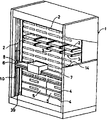
제1도는 본 발명의 한 실시예인 정보기억정형품의 출입반송장치의 일부를 절개한 외관사시도를 나타낸 것이다. 이 도면에서 앞면의 개방된 선반모양의 하우징(1)내의 상반부에는 격벽으로 여러줄로 분할된 각 공간에 비디오카세트테이프(2)를 정렬하는 카세트랙(3)이 형성되어 있다. 또, 상기한 하우징(1)내의 하반부에는 상하에 여러단으로 분할한 덱셀프(deck shelf)(4)가 형성되었고, 덱셀프(4)에는 비디오덱(5)이 정렬 배치되어 있다.Figure 1 shows an external perspective view of a part of the entrance and exit device for the information storage model is an embodiment of the present invention. In this figure, a
하우징(1)의 전면측에는 하우징(1) 전면에 잇따라서 피커(6)를 수평방향으로 주행이 자유롭도록 지지하는 피커지지프레임(7)이 가로 설치되어 있다. 이 피커지지프레임(7)의 일단부에는 제1도의 하우징(l)에 대면하여 좌단부측을 수평으로 단면하여 나타낸 제2도 및 이 좌단부측을 하우징(1)의 안쪽으로부터 본 제3도에 나타낸 바와 같이 부착부재(8)를 개재하여 상하 한쌍의 승강가이드로울러(9)가 설치되어 하우징(1)의 좌단부 측벽에 세로로 설치된 가이드레일(10)을 사용하여 상기한 바 승강가이드로울러(9)를 안내하는 한편 피커지지프레임(7)의 타단부에는 제1도의 하우징의 대면하여 우단부를 수평으로 단면하여 나타낸 제4도 및 상기한 후단부측을 하우징(1)의 안쪽에서 본 제5도에 나타낸 바와 같이 부착부재(l1),(12)를 개재하여 상하 한쌍의 승강가이드로울러(13)가 설치되어, 하우징(1)의 우단부측벽에 세로 설치된 가이드레일(14)로 승강가이드로울러(13)를 안내하고, 이에 따라 피커지지프레임(7)이 전후에 차이지지 않도록 규제되어 있다.On the front side of the
또, 상기한 피커지지프레임(7)의 좌단부의 장치부재(8)에는 제2도 및 제3도에 나타낸 바와 같이 로우프 고정용 막대(15)를 나사식으로 부착하는 한편, 피커지지프레임(7)의 우단부의 부착부재(11)에도 제4도 및 제5도에 나타낸 바와 같이 로우프 고정용 막대(16)가 나사식으로 부착되었으며, 이것들 막대(15),(16)에 고정된 로우프(17),(18)에 의하여 피커지지프레임(7)이 드리워서 지지되어 있다. 더우기, 피커지지프레임(7)의 우단부에서는 하우징(1)의 전후방향으로 회전축을 대면한 다른 한쌍의 승강가이드로울러(19),(20)가 설치되어, 하우징(1)쪽의 가이드레일(14)의 일단부가 이것들 승강가이드로울러(19),(20) 사이에 끼워 있어, 이에 따라 피커지지프레임(7)이 하우징(1)의 폭방향으로 위치 차이가 나지 않도록 규제되어 있다.In addition, as shown in FIGS. 2 and 3, the
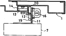
제6도는 하우징(1)의 상부의 수평단면도, 제7도는 하우징(1)의 후단부측을 안쪽으로부터 본 종단면도를 나타낸다. 이것들 도면에서 피커지지프레임(7)을 드리워서 지지하는 이미 설명한 좌우 한쌍의 로우프(17),(18)는 하우징(1)의 상부에 설치된 로우프 가이드로울러(21),(22),(23),(24)에 잇따라 늘어져서 좌우양단부로부터 하우징(1)의 등부분 중앙을 향하여 안내되어 있다.6 is a horizontal sectional view of the upper part of the
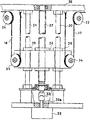
한편, 하우징(1)내에서는 하우징(1)의 상반부에 배열되는 비디오 카세트 테이프(2)와 하우징(1)의 하반부에 배열되는 비디오덱(5)의 깊이 치수의 차에 의하여 등부분 상반부에 일정한 공간이 확보되어 있고, 이 등부분 공간(25)을 이용하여 제6도 및 제7도에 나타낸 바와 같이 균형추(26)가 승강이 자유롭도록 설치되어있다. 이 균형추(26)의 중앙부에는 제8도 및 제9도에 나타낸 바와 같이 상기한 등부분 공간(25)에 회전이 자유롭도록 드리워서 설치된 보올나사(27)를 나사 맞춤함과 동시에 상술한 균형추(26)의 양단부에 설치된 가이드 슬리이브(28),(29)가 보올나사(27)와 평행하여 드리워서 설치된 좌우 한쌍의 가이드축(30),(31)에 미끄러지기 자유롭도록 끼워지고 보올나사(27)의 회전에 따라 균형추(26)가 가이드축(30),(31)에 안내되어 승강 작동하도록 구성되어 있다. 보올나사(27)의 하단부는 제9도에서와 같이 등부분 공간(25)의 하부에 설치된 모우터(32)의 회전축(32a)에 커플링(33)을 개재하여 연결되어 있으며, 모우터(32)의 구동에 따라 보올나사(27)에 회전이 부여된다. 또 균형추(26)의 좌우양측면에는 제6도-제9도에 나타낸 바와 같이 프리로울러(34),(35)가 설치되어 있으며, 이미 설명한 피커지지프레임(7)을 드리워 지지하는 좌우의 각 로우프(17),(18)는 로우프 가이드로울러(21),(22) 및 로우프 가이드로울러(23),(24)를 개재하여 각기 프리로울러(34),(35)에 감겨졌으며, 이것들 로우프(17),(18)의 종단부는 등부분 공간(25)이 천판부(top plate part)(36)에 고정되어 있다. 그리고, 균형추(26)는 피커(6)를 포함한 피커지지프레임(7)과 중량이 대략 균형이 잡히도록 중량 설정이 되어 있으며, 모우터(32)의 약간의 회전력에 따라 피커(6)의 승강을 할 수 있도록 구성되어 있다. 더우기, 균형추(26)의 프리로울러(34),(35)를 동활차(running block)로 이용하므로 피커(6)의 필요로 하는 승강거리에 대하여 균형추(26)의 승강거리는 그 반분으로서 충분하여 소형의 견인구동부를 구성할 수 있다.On the other hand, in the
피커지지프레임(7)의 좌단부에는 제2도 및 제3도에 나타낸 바와 같이 반사면재(37)가 설치되어 있다.At the left end of the
또, 하우징(1)의 가이드레일(10)의 아래 위치에는 제1도에 나타낸 바와 같이 피커(6)의 승강동작영역의 원점을 검출하기 의한 반사형 투수광기(投受光器)(39)가 설치되어 있어서, 전원투입시에는 반드시 피커지지프레임(7)쪽의 반사면재(37)가 상기한 원점 검출용 반사형 투수광기(39)와 대립하는 위치에 복귀하여 항상 그 위치를 원점으로 하여 동작하도록 구성되어 있다. 따라서, 가령 로우프(17),(18)가 늘어져 있다 하여도 전원을 투입할때마다 그에 대한 보정을 이행할 수 있다. 상술한 바 원점위치는 가이드레일(10)의 위쪽 위치에 설정하여도 좋다. 더우기, 이 실시예에서는 이상과 같이 로우프(17),(18)로 피커지지프레임(7)을 드리워서 지지한 구성이기 때문에 그 높이위치를 조정함에 텐셔너 등의 부속품은 불필요하고 조립할때의 장력조정도 생략할 수 있다.In the lower position of the
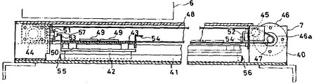
제10도는 피커지지프레임(7)의 수평단면도, 제11도는 피커지지프레임(7)의 정면측으로부터 본 종단면도, 제12도는 우측쪽으로부터 본 종단면도를 나타낸 것이다. 이것들 도면에서 피커지지프레임(7)의 본체케이스(40)는 단면이 대체로 4각형인 통상을 지녔으며, 이 본체케이스(40)내에는 가로방향으로 뻗은 가이드레일(41)이 배치되어 있다. 상기한 가이드레일(41)상에는 슬라이더(42)를 개재하여 피커부착대(43)가 주행이 자유롭도록 실려 있다. 또, 상술한 본체케이스(40)내의 좌단부측에는 풀리(pulley)가, 본체케이스(40)내의 우단부측에는 풀리(45) 및 모우터(46)가 설치되었으며, 상기한 풀리(44),(45) 및 모우터(46)의 회전축(46a)의 풀리(47)에 걸친 이음매 없는 벨트(48)의 일부에 상술한 피커부착대(43)가 연결판(49)에 따라 고정되어 모우터(46)의 구동으로 이음매 없는 벨트(48)가 동작하여 피커부착대가 가이드레일(41)에 잇따라서 좌우로 주행할 수 있도록 구성되어 있다. 더우기, 피커부착대(43)와 슬라이더(42)의 사이에는 내충격고무(50)가 개재 삽입되어 있다.FIG. 10 is a horizontal sectional view of the
상기한 바 본체케이스(40)내의 좌단부 및 우단부에는 최종단 검출용의 리밋스위치(51),(52)가 설치되는 한편, 피커부착대(43)의 좌단부 및 우단부에는 각 리밋스위치(51),(52)에 작용하는 작용부재(53),(54)가 설치되어 피커부착대(43)가 소정의 좌단위치에 도달하면, 작용부재(53)가 리밋스위치(51)에 작용하여 모우터(46)의 구동을 정지하고, 또 피커부착대(43)가 소정의 우단위치에 도달하면 상기한 작용부재(54)가 리밋스위치(52)에 작용하여 모우터(46)의 구동을 정지하도록 구성되어 있다. 더우기, 가이드레일(41)의 좌우양단에는 각기 스토퍼(55),(56)가 설치되어, 리밋스위치(51),(52)에 의한 제어의 효력이 없는 비상의 경우에 이것들 스토퍼(55),(56)로 피커부착대(43)를 정지시키도록 구성되어 있다. 제10도 및 제11도에서 (57)은 무단벨트(48)의 인장조정용 나사이다.As described above, the left end and the right end of the
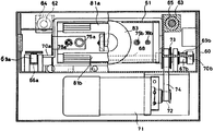
제13도는 피커(6)의 일부를 파단한 수평단면도, 제14도는 피커(6)의 우반부를 종단한 정면도, 제15도는 피커(6)의 우측쪽으로부터 본 종단면도를 나타낸다. 이것들 도면에서, 피커(6)의 본체케이스(60)는 피커부착대(43)에 고정되어 있으며, 본체케이스(60)내에는 상자(61)가 전후로 주행이 자유롭도록 설치되어 있다. 즉, 본체케이스(60)내에는 그 좌우양측부에 전후방향으로 향하여 슬라이드축(62),(63)이 병설되어 있는 한편, 상자(61)의 좌우양측부에는 슬라이드축(62),(63)에 각기 끼워진 슬라이드베어링(64),(65)이 설치되었으며 상자(61)는 슬라이드축(62),(63)에 의하여 주행이 자유롭도록 지지되어 있다. 또, 본체케이스(60)내의 전후에는 각기 좌우 한쌍의 풀리(66a),(66b) 및 풀리(67a),(67b)가 설치되었으며, 풀리(67a),(67b)는 구동축(68)에서 연결되어 상기한 바 풀리(66a),(67a) 사이 및 풀리(66b),(67b) 사이에 각기 이음매 없는 벨트(69a),(69b)를 걸쳐서 벨트 컨베이어(69)가 구성되어 있다. 그리고, 상자(61)는 그 양단부에 형성된 부착부재(70a),(70b)를 상기한 각 이음매 없는 벨트(69a),(69b)에 각기 고정하여 벨트 컨베이어(69)의 구동에 따라 각기 고정하여 벨트 컨베이어(69)의 구동에 따라 슬라이드축(62),(63)의 가이드로 전후에 주행할 수 있도톡 구성되어 있다. 제13도에는 상자(61)가 후방 및 전방에 있는 상태를 도면에 나타내고 있다. 나아가서, 본체케이스(60)의 후부의 구동축(68)은 제15도에 나타낸 바와 같이 본체케이스(60)의 후부아래위치에 설치된 모우터(71)와 풀리(72),(73) 및 이음매 없는 벨트(74)를 개재하여 연결되어 있으며 모우터(71)의 구동에 따라 벨트 컨베이어(69)를 동작시키도록 구성되어 있다. 상술한 상자(61)의 좌우양단부에는 전방으로 향하여 돌출하는 푸셔(75a),(75b)가 진퇴할 수 있도록 설치되어 있음과 동시에 압축코일스프링(76a),(76b)에 따라 돌출방향으로 탄력 가압되어 있다.FIG. 13 is a horizontal cross-sectional view of a part of the
한편 상자(61)내에는 파지장치(77)가 설치되어 있다. 이 파지장치(77)는 상자(61)의 양측부에 전후방향으로 향하여 병설된 슬라이드축(78a),(78b)에 술라이드하기 자유롭도록(즉, 상자(61)에 대하여 전후방향으로 상대이동이 자유롭도록) 지지되어 있음과 동시에 이것들 슬라이드축(78a),(78b)에 끼워진 압출코일스프링(79a),(79b)에 따라 전방으로 향하도록 가압되어 있다.On the other hand, the holding
상기한 파지장치(77)의 앞부분에는 뒷부분이 축(80)에 의하여 서로 피벗 연결된 상하 한쌍의 파지접게(81a),(81b)가 설치되었으며, 각 파지집게(81a),(81b)의 중간부 좌우양단은 제13도 및 제15도에 나타낸 바와같이 각기 핀(82a),(82b)으로 축착되어(제13도에서는 아래쪽 파지집게(81b)의 좌우핀(82b)만을 1점 쇄선으로 나타내고 있다) 핀(82a),(82b)을 받침점으로 하여 개폐동작을 하도록 구성되어 있다. 그리고, 파지장치(77)의 후부에는 파지집게(81a),(81b)를 피벗 연결하는 축(80)에 연결된 플런저를 지닌 솔레노이드(83)가 배치되었으며, 이 솔레노이드(83)의 플런저의 진퇴동작에 따라 상기한 상하 한쌍의 파지집게(81a),(81b)가 개폐동작하도록 구성되어 있다. 축(80)은 푸셔(75a),(75b)의 축에 감겨진 스프링(91)에 따라 전방으로 가압되어서, 파지집게(81a),(81b)에 따라 전방으로 가압되어서, 파지집게(81a),(81b)는 통상 열린 상태에 있고, 솔레노이드(83)의 통전에 따라 탄력에 따라 반발되어 닫혀진다.In the front part of the holding
또, 상기한 본체케이스(60)내의 전부의 소정위치에는 스토퍼(84)가 설치되었으며, 파지장치(77)의 후부로부터 드리워서 설치된 작용부재(85)가 스토퍼(84)에 맞닿음에 따라 파지장치(77)의 진출을 저지하도록 구성되어 있다. 파지장치(77)의 진출이 지지되었을때 모우터(7l)를 더욱 구동함에 따라 상자(61)만이 스프링(79a),(79b)의 탄력에 반발되어 진출하여 푸셔(75a),(75b)를 돌출시킨다.In addition, the
제16도는 앞에서 설명한 카세트랙(3)을 구성하는 각 유닛부재(86)의 사시도를 나타낸 것이고, 제17도는 그 조립상태의 평면도를 나타낸 것이다. 이들 도면에서 카세트(3)의 각 유닛부재(86)는 선단부에 아래방향으로 경사진 가이드면(87a)이 형성된 지지판(87)과 이 지지판(87)의 중간위치에 드리워서 설치되는 분할벽(88)으로 형성되었으며, 분할벽(88)의 전단부에는 테이퍼 형상의 가이드면(88a)이 형성되고, 또 분할벽(88)의 후부측면에는 후방으로 향하여 변화하는 테이퍼 형상의 가이드면(88b)이 형성되어 있다. 그리고, 상기한 분할벽(88)의 후단에 형성된 T자 형상의 고정부(89)를 앞에서 설명한 하우징(1)내에 가로 설치된 제l7도에 나타낸 부착판(90)의 슬릿(90a)에 고정함에 따라 이 도면과 같이 일정한 간격에서 각 유닛부재(86)가 부착되어 카세트랙(3)이 구성된다.FIG. 16 shows a perspective view of each
제18도는 이 실시예의 장치 제어시스템의 블록도를 나타낸 것이다. 이 도면에서, (100)은 앞에서 설명한 승강기구의 모우터(32)를 구동하는 Z축 모우터 드라이버, (101)은 앞에서 설명한 피커 지지프레임(7)의 모우터(46)를 구동하는 X축 모우터 드라이버, (102)는 앞에시 설명한 피커(6)의 모우터(7l)를 구동하는 Y축 모우터 드라이버, (103)은 앞에서 설명한 파지장치(77)의 솔레노이드(83)를 구동하는 솔레노이드 드라이버이며, 이것들 각 드라이버(100-103)의 이것을 제어하는 마이크로컴퓨우터(104) 등에 의하여 제어장치(105)가 구동되어 있다. (111)은 승강기구의 모우터(32)에 설치된 부호기로서, 이 부호기(111)의 펄스를 카운트 함에 따라 마이크로컴퓨우터(104)가 피커(6)의 높이위치를 검출하도록 되어 있다. (112)는 피커지지프레임(7)의 모우터(46)에 설치된 부호기로서, 이 부호기(112)의 펄스를 카운트함에 따라 마이크로컴퓨우터(104)가 피커(6)의 가로주행위치를 검출하도록 되어 있다. (113)은 피커(6)의 모우터(71)에 설치된 부호기로서, 이 부호기(113)의 펄스를 카운트함에 따라 마이크로컴퓨우터(104)가 피커(6)의 진출위치를 검출하도록 되어있다. 그리고, 앞에서 설명한 피커지지프레임(7)에 있어서의 리밋스위치(51),(52) 등의 각종센서(106)의 검출신호를 상기한 마이크로컴퓨우터(104)에 입력하여 일정한 제어지령을 출력하도록 구성되어 있다. 또, 상기한 하우징(1)의 하반부에 배열된 각 비디오덱(5)의 동작도 마이크로컴퓨우터(104)로 제어하도록 전기적 접속이 되어, 마이크로컴퓨우터(104)로부터의 전환신호에 따라 전환기(107)를 제어하여 각 비디오덱(5)과 예컨데 학교의 각 교실 등의 원격지의 각 테레비죤(108)을 임의로 전환 접속할 수 있도록 구성되어 있다. (109)는 모우터 조작반이고, (110)은 원격지측의 각 조작반이다.18 shows a block diagram of the device control system of this embodiment. In this figure,
다음에 상기한 장치의 동작을 설명한다. 제19도에 나타낸 원격지의 하나의 조작반(110)으로부터 제어장치(105)의 마이크로컴퓨우터(104)에 일정한 비디오카세트테이프(2)의 재생지령을 부여하게 되면, 제어장치(105)에서는 그 비디오카세트테이프(2)를 비사용중의 임의의 비데오덱(5)에 장착하는 제어가 다음과 같이 개시된다.Next, the operation of the above apparatus will be described. When a control instruction of the
우선, 하우징(1)의 등부분공간(25)의 모우터(32)가 구동을 개시하여 보올나사(27)의 회전에 따라 균형추(26)가 승강동작한다. 이에 따라, 로우프(17),(18)에 드리워서 지지된 피커지지프레임(7)이 승강동작한다. 피커지지프레임(7)의 승강에 따라 모우터(32)의 부호기(111)의 펄스를 마이크로컴퓨우터(104)가 카운트한다. 지정된 카세트랙(3)의 높이 위치에 상당하는 펄스를 마이크로컴퓨우터(104)가 카운트하면 승강동작은 정지하고, 피커(6)의 높이가 위치결정된다. 더욱이, 장치의 전원투입시에는 앞에서 설명한 바와 원점검출용 투수광기(39)가 검출신호를 출력하는 아래위치에 일단 복귀하여 이로부터 실질상의 승강동작을 개시하므로 비사용시에 로우프(17),(18)에 이완이 발생하는 등의 위치정밀도를 어긋나게 하는 것과 같은 변화가 있을 경우에도 항상 일정한 원점위치를 시발점으로 하여 승강동작이 개시되어, 자동적으로 위치수정을 하게 된다.First, the
한편, 피커지지프레임(7)에서는 모우터(46)가 구동하여 이음매 없는 벨트(48)가 동작하여 이 이음매 없는 무단벨트(48)에 피커부착대(43)를 개재하여 결합되어 있는 피커(6)가 좌우방향으로 주행한다. 본 동작에 따라 모우터(46)의 부호기(112)의 펄스를 마이크로컴퓨우터(104)가 카운트한다. 지정된 카세트랙(3)의 위치에 상당하는 펄스를 마이크로컴퓨우터(104)가 카운트하면 피커(6)의 가로이동은 정지되어, 피커(6)의 가로주행 위치가 위치결정된다. 이상의 동작에 따라 피커(6)는 희망하는 비디오카세트테이프(2)의 앞에 정지한다.On the other hand, in the
이어서 피커(6)의 본체케이스(60)내의 모우터(71)가 구동을 개시하여, 그 회전은 풀리(72), 이음매 없는 벨트(74), 풀리(73)를 개재하여 구동축(68)에 전달되어 벨트컨베이어(69)가 동작한다. 이에 따라 벨트컨베이어(69)의 각 이음매 없는 밸트(69a),(69b)에 고정되어 있는 상자(61)가 진출동작한다. 제13도 및 제15도에서는 상자(61)가 후퇴하고 있는 상태와 진출한 상태를 함께 나타내고 있다. 진출동작시에는 파지장치(77)의 솔레노이드(83)에 통전이 이루어지지 않으며, 파지집게(81a),(81b)는 개방자세를 유지하고 있다. 푸셔(75a),(75b)의 선단이 제20도에 나타낸 바와 같이 카세트랙(4)내의 비디오카세트테이프(2)의 전면에 맞닿아서 상자(61)의 진출이 저지되는 위치에 도달하면, 솔레노이드(83)에 통전이 이루어져서 파지집게(81a),(81b)의 축(80)이 후방으로 끌리기 때문에 각 파지집게(81a),(81b)는 각기 핀(82a),(82b)을 받침점으로 하여 폐쇄하는 방향으로 희동하고, 이에 따라 비디오카세트테이프(2)의 앞부분이 파지집게(81a),(81b)로 붙잡게 된다. 그런다음, 모우터(71)는 진출동작시와는 역방향으로 회전구동을 전환하게 되어, 벨트컨베이어(69)가 후퇴측으로 향하여 동작을 개시한다.Subsequently, the
그때문에, 상자(61)가 후퇴하여 파지집게(81a),(81b)에 붙잡한 비디오카세트테이프(2)는 카세트랙(3)으로부터 인출되고, 좌우의 이음매 없는 벨트(69a),(69b) 전단의 만곡부(풀리감기부)에 옮기어 벨트컨베이어(69)에 실리게 된다. 그리고, 이런 상태에서 벨트컨베이어(69)에 의하여 구동되는 상자(61)와 같은 속도로 후방으로 운반된다. 이때문에 파지집게(81a),(81b)의 파지력으로서는 그다지 센것은 요구되지 않는다. 인출시의 비디오카세트테이프(2)의 위치변위(dislocation) 중에서 좌우 및 깊이방향의 것은 피커(6) 내에 비디오카세트테이프(2)의 통과스페이스를 충분히 설치하는 것으로 대처할 수 있으며, 이에 따라 비디오카세트테이프(2)와 피커(6)의 외벽의 불필요한 마찰을 회피하여 비디오카세트테이프(2)를 마찰상처로부터 보호할수 있다. 또, 상하방향의 위치변위에 대하여는 전술한 바와 같은 비디오카세트테이프(2)의 좌우의 이음매없는 벨트(69a),(69b)의 전단만곡부에 옮김에 따라 대처할 수 있고, 나아가서 파지장치(77)가 슬라이드축(78a),(78b)에 대하여 약간의 자유도(덜렁거림)를 지니도록 구성하여 두면, 비디오카세트데이프(2)의 위치 차이에 대응하여 파지집게(81a),(8lb)가 자유롭도록 상하운동하여 비디오카세트테이프(2)의 보호를 도모하게 된다.Therefore, the
그런다음, 전술한 바와 대략 마찬가지의 동작에 따라 피커(6)의 높이위치와 가로방향위치가 변경되어 지정된 비디오덱(5)의 앞에서 피커(6)가 정지한다.Then, the height position and the horizontal position of the
따라서, 피커(6)에 따라 비디오카세트테이프(2)가 비디오덱(5)내에 장착된다.Thus, the
이때의 진출동작시에는 제21도(A)에 나타낸 바와 같이 파지집게(81a),(81b)는 개방자세로 유지되며, 비디오카세트테이프(2)는 단순히 벨트컨베이어(61) 위에 실린 그대로의 상태에서 운반된다. 푸셔(75a),(75b)는 비디오카세트테이프(2)와 벨트컨베이어(61) 사이에 미끄럼이 발생하였을 경우의 푸셔로서 작용한다. 그리고, 비디오카세트테이프(2)의 앞부분이 비디오덱(5)에 다다르게 되어 벨트컨베이어(61)로 송급할 수 없게되면 이번에는 상자(61)의 진출동작에 따른 푸셔(75a),(75b)의 푸싱작용에 따라 비디오 카세트테이프(2)는 비디오덱(5)에 밀어넣게 된다. 이때 피지장치(77)의 진출은 작용부재(85)가 스토퍼(84)에 맞닿아서 저지되지만 벨트컨베이어(69)의 구동은 더욱더 계속하여 하게 된다. 그때문에, 파지장치(77)와 상자(61) 사이에 개재 장착된 압축코일스프링(79a),(79b)의 가압력에 저항하여 상자(61)가 더욱 진출동작하고, 이에 따라서 푸셔(75a),(75b)가 돌출하여 제21도(B)에 나타낸 바와 같이 비디오카세트테이프(2)를 비디오덱(5) 내에 밀어 넣는다. 이와 같은 강압하는 양은 비디오덱(5)측의 인입기구( 引
![]()
![]()
비디오덱(5)으로부터 인출된 비디오카세트테이프(2)를 원래의 카세트랙(3)에 복귀시키는 동작도, 비디오덱(5)으로의 장착하는 동작과 대체로 마찬가지이며, 그 동작상태를 제19도에 나타내고 있다. 단, 본 동작에서는 파지장치(77) 정지후의 푸셔(75a),(75b)에 의한 강압동작은 불필요하므로, 파지장치(77)의 작용부재(85)가 스토퍼(84)에 맞닿는 위치에서 벨트컨베이어(69)의 동작은 정지한다. 또, 비디오카세트테이프(2)를 카세트랙(3)에 밀어 넣는 이러한 동작의 경우, 앞에서 설명한 바와 같이 파지집게(81a),(81b)로 붙잡지 않고 단순히 벨트컨베이어(69) 위에 실린 상태에서 도중까지 운반되며, 최후에는 푸셔(75a),(75b)로 밀어 넣는 것 뿐이므로, 비디오카세트테이프(2)를 밀어넣는 위치가 카세트랙(3)의 위치로부터 다소 어긋나 있다 하여도 카세트랙(3)을 구성하는 유닛부재(86)에 형성된 각 가이드(87a),(88a),(88b)에 의하여 이와 같은 위치차이는 제17도에 가상선으로 나타낸 바와 같이 원활하게 보정된다. 즉, 이 도면에서 위치 차이진 상태에서 카세트랙(3)에 향하는 비디오카세트테이프(2)는 우선 상기한 도면에서 부호 I로 나타낸 바와 같이 지지판(87)의 전단부의 가이드면(87a)에서 상하의 위치차이를 수정함과 동시에 분할벽(88) 앞가장자리의 가이드면(88a)에서 가로방향의 위치차이가 수정된다.The operation of returning the
따라서, 비디오카세트테이프(2)가 반부 이상 카세트랙(3)내에 도입되면, 그 다음에는 분할벽(88)후부의 가이드면(88b)에 따라 가로방향의 위치차이가 다시금 부호 II로 나타낸 바와 같이 수정되고, 최종적으로 부호 III에 나타낸 바와 같이 바른 위치에 수납된다. 본 실시예에서는 카세트랙(3)의 경우에 대하어서만 가이드기구를 부가하였을 경우를 나타내고 있으나, 비디오덱(5)에 대하여도 상술한 바와 같이 유사한 가이드기구를 부가하여도 좋다.Therefore, when the
더욱이, 여기에서는 비디오카세트테이프(2)를 비디오덱(5)에 장착한다거나 비디오덱(5)으로부터 원래의 카세트랙(3)에 복귀시키는 비디오테이프의 경우를 예시하여 설명하였으나, 그밖에 비디오디스크, 플로피(floppy) 디스크 등 정보를 기억한 정형품을 정보판독장치에 출입하는 경우에도 적용할 수 있다는 것은 더 말할것도 없다.Moreover, although the case of the video tape which mounts the
이상과 같이 본 발명을 도면에 나타낸 실시예에 대하여 상세히 설명하였으나, 본 발명은 상술한 실시예에 한정되는 것은 아니다. 본 발명의 범위는 다음의 청구의 범위에 따라 규정되어야 한다.As mentioned above, although the Example which showed this invention in the drawing was demonstrated in detail, this invention is not limited to the above-mentioned Example. The scope of the invention should be defined according to the following claims.
[도면의 간단한 설명][Brief Description of Drawings]
제1도는 본 발명의 한 실시예인 정보기억정형품의 출입반송장치의 외관경사도.1 is an external inclination diagram of an apparatus for carrying out an information storage standard product according to an embodiment of the present invention.
제2도는 하우징의 좌단부측의 수평단면도.2 is a horizontal cross-sectional view of the left end side of the housing.
제3도는 하우징의 좌단부측을 안쪽으로부터 본 정면도.3 is a front view of the left end side of the housing as seen from the inside;
제4도는 하우징의 우단부측의 수평단면도.4 is a horizontal cross-sectional view of the right end side of the housing.
제5도는 하우징의 우단부측을 안쪽으로부터 본 정면도.5 is a front view of the right end side of the housing as seen from the inside;
제6도는 하우징의 수평단면도.6 is a horizontal cross-sectional view of the housing.
제7도는 하우징의 옆쪽으로부터 본 종단면도.7 is a longitudinal sectional view seen from the side of the housing.
제8도는 균형추(counter weigh)의 평면도.8 is a plan view of a counterweight.
제9도는 승강기구의 주요부분을 하우징의 배면측에서 본 정면도.9 is a front view of the main part of the elevating mechanism as seen from the rear side of the housing;
제10도는 피커지지프레임의 평면도.10 is a plan view of the picker support frame.
제11도는 피커지지프레임의 정면도로부터 본 종단면도.11 is a longitudinal sectional view of the picker support frame as seen from the front view.
제12도는 피커지지프레임의 옆쪽에서 본 종단면도.12 is a longitudinal sectional view seen from the side of the picker support frame.
제13도는 피커의 수평단면도.13 is a horizontal cross-sectional view of the picker.
제l4도는 피커의 정면쪽에서 본 종단면도.Fig. 4 is a longitudinal sectional view seen from the front side of the picker.
제15도는 피커의 옆쪽에서 본 종단면도.15 is a longitudinal cross-sectional view of the picker.
제16도는 카세트랙의 유닛부재의 사시도.16 is a perspective view of a unit member of a cassette rack.
제17도는 카세트랙에의 비디오카세트테이프의 수납동작을 나타낸 설명도.FIG. 17 is an explanatory diagram showing the storing operation of a video cassette tape in a cassette rack; FIG.
제18도는 제이시스템을 나타낸 블록도.18 is a block diagram showing a J system.
제19도는 비디오카세트테이프의 카세트랙에의 수납동작을 나타낸 설명도.Fig. 19 is an explanatory diagram showing the storing operation of the cassette cassette in the cassette rack.
제20도는 비디오카세트테이프의 카세트랙으로부터 들어내는 동작을 나타낸 설명도.20 is an explanatory diagram showing an operation of lifting out a cassette rack of a video cassette tape;
제21도(A),(B)는 비디오카세트테이프의 비디오 덱(vldeo deck)에의 장착동작을 나타낸 설명도.21A and 21B are explanatory views showing the mounting operation of a video cassette tape to a video deck.
Claims (9)
Applications Claiming Priority (5)
| Application Number | Priority Date | Filing Date | Title |
|---|---|---|---|
| JP86-92246 | 1986-06-16 | ||
| JP1986092247U JPH0749652Y2 (en) | 1986-06-16 | 1986-06-16 | Video cassette loading / unloading device |
| JP86-92247 | 1986-06-16 | ||
| JP1986092246U JPH05999Y2 (en) | 1986-06-16 | 1986-06-16 | |
| PCT/JP1987/000368 WO1987007751A1 (en) | 1986-06-16 | 1987-06-09 | Conveyor device for storing and retrieving information storing regular article |
Publications (2)
| Publication Number | Publication Date |
|---|---|
| KR880701439A KR880701439A (en) | 1988-07-27 |
| KR960009228B1 true KR960009228B1 (en) | 1996-07-16 |
Family
ID=26433708
Family Applications (1)
| Application Number | Title | Priority Date | Filing Date |
|---|---|---|---|
| KR1019880700178A KR960009228B1 (en) | 1986-06-16 | 1987-06-09 | Carrier apparatus for taking information-storage regular articles in and out |
Country Status (4)
| Country | Link |
|---|---|
| US (1) | US4945430A (en) |
| KR (1) | KR960009228B1 (en) |
| DE (2) | DE3790313C2 (en) |
| WO (1) | WO1987007751A1 (en) |
Families Citing this family (25)
| Publication number | Priority date | Publication date | Assignee | Title |
|---|---|---|---|---|
| US5388946A (en) * | 1988-01-20 | 1995-02-14 | Grau Gmbh & Co. | Systems and methods for the automated archiving and retrieval of computer data storage cassettes |
| US4984108A (en) * | 1988-12-16 | 1991-01-08 | Datatape Incorporated | Apparatus for transporting magnetic tape cassettes of different sizes |
| JPH04268247A (en) * | 1991-02-22 | 1992-09-24 | Mitsubishi Electric Corp | Device and for method carrying disk cartridge |
| JPH052802A (en) * | 1991-06-26 | 1993-01-08 | Sony Corp | Cassette transport machine |
| JPH05128675A (en) * | 1991-11-05 | 1993-05-25 | Sony Corp | Automatic cassette changer |
| US5285333A (en) * | 1991-12-27 | 1994-02-08 | Archive Corporation | Mass storage and retrieval system for magnetic tape cartridges |
| GB2267382A (en) * | 1992-05-23 | 1993-12-01 | Ibm | Robotic manipulator |
| DE4317546A1 (en) * | 1992-05-27 | 1994-01-20 | Funai Electric Co | Record player with automatic record changer |
| US5596556A (en) * | 1993-02-18 | 1997-01-21 | Hewlett-Packard Company | Linear displacement and support apparatus for use in a cartridge handling system |
| NL9400141A (en) * | 1994-01-28 | 1995-09-01 | Wimm Hellebaut | Apparatus for treating flat objects |
| US5995469A (en) * | 1994-07-13 | 1999-11-30 | Mitsumi Electric Co., Ltd. | Disk device having movable cartridge holder and a cam plate having a cam groove with three successive inclined cam groove portions |
| US5661287A (en) * | 1995-04-28 | 1997-08-26 | Breece Hill Technologies, Inc. | Multi-purpose laser/optical sensor in a storage library subsystem |
| CA2287897C (en) * | 1997-04-30 | 2004-10-12 | Spectra Logic Corporation | Data cartridge library system |
| US5886974A (en) * | 1997-06-18 | 1999-03-23 | Multidisc Technologies | Compact disc loader and transport apparatus |
| US5912873A (en) * | 1997-06-18 | 1999-06-15 | Multidisc Technologies | Compact disc transporter with dual transport sites |
| US5886960A (en) * | 1997-11-04 | 1999-03-23 | Multidisc Technologies | Optical disc system using multiple optical heads for accessing information data |
| US6160786A (en) * | 1998-03-20 | 2000-12-12 | Hewlett-Packard Company | Cartridge engaging assembly with rack drive thumb actuator system |
| WO2000028537A1 (en) * | 1998-11-11 | 2000-05-18 | Nsm Jukebox Gmbh | Play-back and/or recording device for disks |
| US6157513A (en) | 1999-01-26 | 2000-12-05 | Hewlett-Packard Company | Thumb referencing and drive system |
| US6826008B2 (en) * | 2000-11-09 | 2004-11-30 | Patentia Hergiswil Ag | Device for transferring a cartridge |
| US7334978B2 (en) * | 2003-06-23 | 2008-02-26 | Hewlett-Packard Development Company, L.P. | Cartridge-handling apparatus for a media storage system |
| US20050036408A1 (en) * | 2003-08-15 | 2005-02-17 | Quantum Corporation | Automated storage library cartridge gripper with cartridge detector |
| US7212375B2 (en) * | 2003-08-15 | 2007-05-01 | Quantum Corporation | Automated storage library gripper apparatus and method |
| JP4376092B2 (en) * | 2004-03-01 | 2009-12-02 | パナソニック株式会社 | Cassette library device |
| DE102005002595B4 (en) * | 2005-01-20 | 2007-02-08 | Holzma Plattenaufteiltechnik Gmbh | Gripping device, in particular collet, for use in a feed device for plate-shaped workpieces |
Family Cites Families (13)
| Publication number | Priority date | Publication date | Assignee | Title |
|---|---|---|---|---|
| US3536194A (en) * | 1967-02-27 | 1970-10-27 | Mosler Safe Co | Document retrieval and handling system |
| JPS4924406A (en) * | 1972-06-26 | 1974-03-04 | ||
| AU518495B2 (en) * | 1976-07-16 | 1981-10-01 | Consolidated Electronic Industries Pty. Ltd. | Automatic tape cartridge selection, handling and replay apparatus |
| DE2911615A1 (en) * | 1979-03-24 | 1980-10-02 | Bosch Gmbh Robert | AUTOMATIC PLAYER AND REPLACEMENT FOR TAPE CASSETTE |
| NL8102495A (en) * | 1981-05-21 | 1982-12-16 | Philips Nv | MODULAR DATA STORAGE DEVICE. |
| JPS57198571A (en) * | 1981-05-30 | 1982-12-06 | Yachiyo Denki Sangyo:Kk | Tape player for 8-track cartridge |
| JPS57198572A (en) * | 1981-05-30 | 1982-12-06 | Yachiyo Denki Sangyo:Kk | Tape player for 8-track cartridge |
| JPS5814268U (en) * | 1981-07-17 | 1983-01-28 | 富士通株式会社 | access mechanism |
| JPS5814268A (en) * | 1981-07-20 | 1983-01-27 | Fuji Electric Co Ltd | Starting system for multi-processor system |
| US4527262A (en) * | 1982-07-28 | 1985-07-02 | Manto Incorporated | Information storer and retriever |
| AU578621B2 (en) * | 1983-08-31 | 1988-11-03 | Sony Corporation | Device for exchanging disks |
| US4675856A (en) * | 1984-07-11 | 1987-06-23 | Filenet Corporation | Optical storage and retrieval device |
| US4766581A (en) * | 1984-08-07 | 1988-08-23 | Justin Korn | Information retrieval system and method using independent user stations |
-
1987
- 1987-06-09 DE DE3790313A patent/DE3790313C2/en not_active Expired - Fee Related
- 1987-06-09 WO PCT/JP1987/000368 patent/WO1987007751A1/en active Application Filing
- 1987-06-09 KR KR1019880700178A patent/KR960009228B1/en not_active IP Right Cessation
- 1987-06-09 DE DE19873790313 patent/DE3790313T1/de active Pending
-
1989
- 1989-04-18 US US07/339,897 patent/US4945430A/en not_active Expired - Fee Related
Also Published As
| Publication number | Publication date |
|---|---|
| DE3790313C2 (en) | 1997-07-17 |
| US4945430A (en) | 1990-07-31 |
| DE3790313T1 (en) | 1988-06-23 |
| WO1987007751A1 (en) | 1987-12-17 |
| KR880701439A (en) | 1988-07-27 |
Similar Documents
| Publication | Publication Date | Title |
|---|---|---|
| KR960009228B1 (en) | Carrier apparatus for taking information-storage regular articles in and out | |
| US4815055A (en) | Data medium storage and retrieval devices | |
| US4215827A (en) | Film loop apparatus | |
| KR19990067467A (en) | Multi-drive multi-magazine mass storage and retrieval unit for tape cartridges | |
| US4984108A (en) | Apparatus for transporting magnetic tape cassettes of different sizes | |
| US5285335A (en) | Cassette transfer unit | |
| KR100286240B1 (en) | Automatic Cassette Library Control | |
| KR870010524A (en) | Cassette feeder | |
| JP3338442B2 (en) | Autoloader for magnetic tape cartridge | |
| EP0242144B1 (en) | Cassette or cartridge auto-changers | |
| KR19980032320A (en) | Wafer Ring Feeder | |
| JPS6135617B2 (en) | ||
| US5752668A (en) | Tape library cartridge manipulation gripper with z-axis translation | |
| JPH05999Y2 (en) | ||
| JPH0749652Y2 (en) | Video cassette loading / unloading device | |
| US4984107A (en) | Apparatus for transporting a magnetic tape cassette | |
| JPH0433187A (en) | Optical card continuous processor | |
| JPS60182047A (en) | Cassette automatic loader | |
| CN217212313U (en) | Receive material belt buffer | |
| CN211180089U (en) | FPC testing arrangement | |
| US20010051086A1 (en) | Automated feed mechanism for electronic components of silicon wafer | |
| JP2841499B2 (en) | Cassette Auto Changer | |
| JP3518785B2 (en) | Cartridge transport method and apparatus | |
| JPH0731398Y2 (en) | Cassette auto changer | |
| JPH0743795Y2 (en) | Cassette auto changer |
Legal Events
| Date | Code | Title | Description |
|---|---|---|---|
| A201 | Request for examination | ||
| E902 | Notification of reason for refusal | ||
| G160 | Decision to publish patent application | ||
| E701 | Decision to grant or registration of patent right | ||
| GRNT | Written decision to grant | ||
| LAPS | Lapse due to unpaid annual fee |