KR940000946B1 - Digital modulation method - Google Patents
Digital modulation method Download PDFInfo
- Publication number
- KR940000946B1 KR940000946B1 KR1019900004961A KR900004961A KR940000946B1 KR 940000946 B1 KR940000946 B1 KR 940000946B1 KR 1019900004961 A KR1019900004961 A KR 1019900004961A KR 900004961 A KR900004961 A KR 900004961A KR 940000946 B1 KR940000946 B1 KR 940000946B1
- Authority
- KR
- South Korea
- Prior art keywords
- bit
- code
- digital
- codes
- digital modulation
- Prior art date
Links
Images


Classifications
-
- H—ELECTRICITY
- H03—ELECTRONIC CIRCUITRY
- H03K—PULSE TECHNIQUE
- H03K7/00—Modulating pulses with a continuously-variable modulating signal
-
- H—ELECTRICITY
- H03—ELECTRONIC CIRCUITRY
- H03M—CODING; DECODING; CODE CONVERSION IN GENERAL
- H03M5/00—Conversion of the form of the representation of individual digits
- H03M5/02—Conversion to or from representation by pulses
- H03M5/04—Conversion to or from representation by pulses the pulses having two levels
- H03M5/14—Code representation, e.g. transition, for a given bit cell depending on the information in one or more adjacent bit cells, e.g. delay modulation code, double density code
- H03M5/145—Conversion to or from block codes or representations thereof
Landscapes
- Engineering & Computer Science (AREA)
- Theoretical Computer Science (AREA)
- Signal Processing For Digital Recording And Reproducing (AREA)
- Detergent Compositions (AREA)
Abstract
내용 없음.No content.
Description
제1도는 본 발명의 디지탈 변조 방법의 제 1 실시예에 따른 디지탈 변조를 실행하는 디지탈 변조 장치를 보여주는 블록 다이어그램.1 is a block diagram showing a digital modulation device for performing digital modulation according to the first embodiment of the digital modulation method of the present invention.
제2도는 디코딩 회로의 한 실시예를 보여주는 블록 다이어그램.2 is a block diagram showing one embodiment of a decoding circuit.
제3a도는 재생된 신호의 캐리어 대 잡음비를 111 주는 그래프.3A is a graph of 111 giving the carrier-to-noise ratio of a reproduced signal.
제3b도는 본 발명의 제 1 실시예의 전력 스펙트럼을 보여주는 그래프.3b is a graph showing the power spectrum of the first embodiment of the present invention.
제3c도는 스크램블된 NRZ의 전력 스펙트럼을 보여주는 그래프.3C is a graph showing the power spectrum of the scrambled NRZ.
제4도는 CDS![]()
![]()
제5도는 CDS![]()
![]()
제6도는 본 발명의 디지탈 변조 방법의 제 2 실예에 따른 디지탈 변조를 실행하는 디지탈 변조 장치를 보여주는 블록 다이어그램.6 is a block diagram showing a digital modulation device for performing digital modulation according to the second embodiment of the digital modulation method of the present invention.
제7도는 제 2 실시예에 따른 디지탈 변조를 실행하는 디지탈 변조 장치의 변조 절차를 보여주는 흐름도.7 is a flowchart showing a modulation procedure of a digital modulation device for performing digital modulation according to the second embodiment.
제8도는 CDS![]()
![]()
제9도는 CDS![]()
![]()
* 도면의 주요 부분에 대한 부호의 설명* Explanation of symbols for the main parts of the drawings
2 : 엔코더 4 : DSV 계산부2: encoder 4: DSV calculation unit
5 : DSV 계산부 8 : 병렬-직렬 변환기5: DSV calculator 8: parallel-to-serial converter
10 : 기록부10: register
본 발명은 8비트 디지탈 데이타를 14비트 디지탈 변조 코드로 변환하는 디지탈 변조 방법에 관한 것이다.The present invention relates to a digital modulation method for converting 8-bit digital data into a 14-bit digital modulation code.
디지탈 데이타를 자기테이프에 기록하거나 자기테이프상에 기록된 디지탈 데이타를 재생하는 종래의 장치는 디지탈 데이타를 기록 또는 재생하기 위해 로터리 변환기를 이용한다. 기록은 디지탈 데이타를 로터리 변환기를 통해 로터리 헤드에 제공하므로써 실행되고 로터리 변환기를 통해 로터리 자기 헤드로 디지탈 신호를 판독하므로써 실행된다. 결과적으로, 재생된 신호가 DC(직류) 성분을 포함한다면, 디지탈 데이타는 올바르게 재생될 수 없다. 이러한 이유때문에, 디지탈 데이타는 DC 없는 디지탈 변조 시스템을 이용해 기록해야만 한다.Conventional apparatus for recording digital data on magnetic tape or reproducing digital data recorded on magnetic tape uses a rotary converter to record or reproduce digital data. Writing is performed by providing digital data to the rotary head via the rotary converter and by reading the digital signal into the rotary magnetic head via the rotary converter. As a result, if the reproduced signal contains a DC (direct current) component, the digital data cannot be reproduced correctly. For this reason, digital data must be recorded using a digital modulation system without DC.
종래의 DC 없는 디지탈 변조 시스템중에는 다음과 같은 시스템이 널리 알려져 있다.Among the conventional DC-free digital modulation systems, the following systems are widely known.
DR(밀도비)이 0.8인 8-10 변조 시스템은 일본 특허출원 공개 제56-19506호에 기술되어 있다.An 8-10 modulation system with a DR (density ratio) of 0.8 is described in Japanese Patent Application Laid-open No. 56-19506.
DR이 1인 변조 시스템으로서는 M2변조 시스템이 알려져 있다.As a modulation system in which DR is 1, an M 2 modulation system is known.
DR이 1.14인 변조 시스템으로서는 일본 특허출원 공개 제61-196469호에 기술되어 있는 8-14 변조 시스템이 알려져 있다. 이 시스템은 각각의 8비트 디지탈 데이타에 대해 14-비트 디지탈 변조 코드를 4개 까지 제공한다. 14비트 변조 코드의 CDS(코드 워드 디지탈 합)이 0일때, 코드는 그것의 반전 패턴과 함께 쌍을 이룬다. 14비트 디지탈 변조 코드의 CDS가 0이 아니면, 코드는 다음의 3코드와 그룹으로 된다 : CDS의 절대값 및 부호가 상기 코드의 것과 다른 14비트 변조 코드 ; 및 각각의 코드의 반전 패턴.As a modulation system having a DR of 1.14, an 8-14 modulation system described in Japanese Patent Application Laid-Open No. 61-196469 is known. The system provides up to four 14-bit digital modulation codes for each 8-bit digital data. When the CDS (code word digital sum) of a 14-bit modulation code is zero, the code is paired with its inversion pattern. If the CDS of the 14-bit digital modulation code is not 0, the code is grouped into the following three codes: a 14-bit modulation code whose absolute value and sign of the CDS are different from those of the code; And inversion pattern of each code.
여기서 CDS는 변조 코드의 제 1 비트에서 마지막 비트까지 계산된 DSV로 정의하며, DSV(디지탈 합 값)은 일련의 디지탈 변조 코드에 있는 각각의 비트 “0”에 대해 -1을 더하므로써 그리고 일련의 디지탈 변조코드에 있는 각각의 비트 “1”에 대해 1을 더하므로써 얻어진 전체합이다. 반전 패턴은 한 코드에 있는 각각의 비트를 반전시키므로써 얻어진 패턴이다 : 비트 “1”은 “0”으로 반전되는 한편 비트 “0”은 “1”로 반전된다.Where CDS is defined as the DSV calculated from the first bit to the last bit of the modulation code, and the DSV (digital sum value) is defined by adding -1 to each bit “0” in the series of digital modulation codes and The sum is obtained by adding 1 to each bit “1” in the digital modulation code. The inversion pattern is a pattern obtained by inverting each bit in a code: bit "1" is inverted to "0" while bit "0" is inverted to "1".
상술된 종래의 변조 시스템들은 다음과 같은 문제점을 갖고 있다.The conventional modulation systems described above have the following problems.
8-10 변조 시스템은 그것의 낮은 0.8 DR 때문에 고밀도 기록에는 적절치 못하다.The 8-10 modulation system is not suitable for high density recording because of its low 0.8 DR.
M2변조 시스템은 그것의 1인 DR 때문에 고밀도 기록에 한정된다.The M 2 modulation system is limited to high density recording because of its 1 DR.
8-14 변조 시스템은 각각의 8비트 코드에 대해 4변조 코드까지 갖고 있고, 디지탈 변조 코드의 CDS의 절대값은 6까지 허용된다. 또한 코드 스트림으로된 각각의 14비트 변조 코드의 끝에서 DSV는 ±4까지 허용되고, 일련의 14비트 디지탈 변조 코드에 있는 각 비트에서 DSV는 ±9까지 허용된다. 결과적으로, 변조코드의 DC 성분을 짧은 시간에 제거하는 것이 어렵고, 그 때문에 저주파수 성분이 로터리 변환기를 갖춘 기록/재생 시스템에서 적당히 통과되어야만 한다.The 8-14 modulation system has up to four modulation codes for each 8 bit code, and the absolute value of the CDS of the digital modulation code is allowed up to six. Also, DSV is allowed up to ± 4 at the end of each 14-bit modulation code in the code stream, and DSV is allowed up to ± 9 at each bit in a series of 14-bit digital modulation codes. As a result, it is difficult to remove the DC component of the modulation code in a short time, so that the low frequency component must be properly passed in a recording / reproducing system equipped with a rotary converter.
8-14 변조 시스템은 다른 문제점이 더 있다. 일반적으로 말하면 자기 테이프의 자화 깊이는 자화된 파장의 약 1/4이다. 기록 신호들이 테이프상에 재기록(over-writing) 될때, 다음과 같은 문제점이 발생한다 : 가장 짧게 자기화된 파장의 4배 이상인 가장 길게 기록된 파장상에 가장 짧게 자기화된 파장의 새로운 신호를 기록하면 기록 매체의 가장 깊은 부분에 남아 있는 잔재가 지워지지 않는 결과가 나타난다. 이러한 지워져야한 자재(residue)는 새로운 신호의 재생동안 나타나고, 그 때문에 재기록이 실제로 어렵게 된다.The 8-14 modulation system has other problems. Generally speaking, the magnetization depth of the magnetic tape is about one quarter of the magnetized wavelength. When write signals are over-written on a tape, the following problems arise: recording a new signal of the shortest magnetized wavelength on the longest recorded wavelength, which is more than four times the shortest magnetized wavelength. The result is that the residue remaining in the deepest portion of the recording medium is not erased. This erased material appears during reproduction of a new signal, which makes the rewriting practically difficult.
그래서, 8-14 변조 시스템은 8-14 변조 코드 트레인내의 연속한 동일 비트(“0” 또는 “1”)수가 2-9이기 때문에 재 기록을 실행할때 지워져야할 잔재에 의해 발생되는 문제점에 봉착하게 된다. 이하의 설명에서 “연속한 동일 비트”란 용어는 2 이상의 연속한 동일 비트를 의미하는데, 예컨대, “000” 또는 “11”을 들수 있다.Thus, the 8-14 modulation system encounters the problem caused by the remnants that should be erased when rewriting because the number of consecutive identical bits (“0” or “1”) in the 8-14 modulation code train is 2-9. Done. In the following description, the term “sequential same bits” means two or more consecutive identical bits, for example, “000” or “11”.
그러므로, 본 발명의 목적은 상기 문제점들을 해소할 수 있는 디지탈 변조 시스템을 제공하는 것이다. 본 발명에 따른 이러한 변조 시스템은 고밀도로 기록을 할 수 있고, DC 성분을 아주 효과적으로 줄일 수 있으며, 애지무스 기록(azimuth recording) 및 재기록도 실행할 수 있다.It is therefore an object of the present invention to provide a digital modulation system which can solve the above problems. Such a modulation system according to the present invention can record at a high density, can effectively reduce the DC component, and can perform azimuth recording and rewriting.
본 발명의 제 1 양상에 따르면, 8비트 디지탈 데이타를 14비트 디지탈 변조 코드로 변환하는 디지탈 변조 방법은, 각각의 8-비트 디지탈 데이타를, (a) 21414-비트 디지탈 코드중에서, 연속한 동일 비트의 수가 제1의 6비트에서는 5 또는 그 이하이고 제 2 비트에서 제13비트까지에서는 2-7이고 마지막 7비트에서는 6 또는 그 이하이며, CDS(코드 워드 디지탈 합)의 절대값이 4 이하인 디지탈 코드를 선택하고, 이러한 선택 절차를 반복하는 절차, (b) 절차(a)에서 선택된 14비트 디지탈 코드중에서, 제 1 비트가 “0”이고 CDS 값이 0인 디지탈 코드를 선택하고, 2개의 디지탈 코드를 1그룹으로 만들기 위해 상기 선택된 14비트 디지탈 코드와 그것의 반전 코드를 쌍으로 하고, 또는 절차(a)에서 선택된 14비트 디지탈 코드중에서, 제 1 비트가 “1”이고 CDS의 값이 +2 또는 +4인 디지탈 코드를 선택하고, 선택된 14비트 디지탈 코드와 그것의 반전 코드를 결합하고, 또한 4 디지탈 코드를 1그룹으로 만들기 위해 상기 절차에서 선택된 14-비트 디지탈 코드 쌍과 두개의 14비트 디지탈 코드를 결합하고, 이러한 선택 절차를 반복하는 절차, (c) 절차(a)에서 선택된 14비트 디지탈 코드중에서, 제 1 비트가 “0”이고 CDS의 값이 -2인 디지탈 코드와 제 1 비트가 “1”인 CDS의 값이 +2 또는 +4인 또 하나의 디지탈 코드를 선택하고, 4개의 디지탈 코드를 1그룹으로 만들기 위하여 두개의 선택된 14비트 디지탈 코드와 그것의 반전 코드를 결합하고, 이러한 선택 절차를 반복하는 절차, (d) 절차(a)에서 선택된 14비트 디지탈 코드중에서, 제 1 비트가 “0”이고 CDS 값이 +4인 디지탈 코드와 제 1 비트가 “1”이고 CDS 값이 +2인 또 하나의 디지탈 코드를 선택하고, 4개의 디지탈 코드를 1그룹으로 만들기 위하여 두개의 선택된 14비트 디지탈 코드와 그것의 반전 코드를 결합하고, 이러한 선택 절차를 반복하는 절차, 및 (e) 상기 절차들에서 형성된 그룹들중 256 그룹을 14비트 디지탈 변조 코드로서 선택하는 절차에 의해 선택된 14비트 디지탈 변조 코드를 4개까지 선택하는 단계 1과 ; 14비트 디지탈 변조 코드의 256 그룹중에서 입력된 8-비트 디지탈 데이타에 해당하는 한 그룹의 14비트 디지탈 변조 코드를 선택하는 단계 2와 ; 이미 선택된 선행의 14비트 디지탈 변조 코드와 선택될 14비트 디지탈 변조 코드의 결합부에서 연속한 동일 비트수가 2-7이라는 필요 요건을 만족시키는 하나 도는 그 이상의 14-비트 디지탈 변조 코드를 단계 2에서 선택된 그룹에서 더 선택하는 단계 3 ; 하나의 14비트 디지탈 변조 코드가 변조 코드의 각 비트에서의 DSV(이하에서 비트 DSV라 함)의 절대값이 7과 같거나 또는 작다는 필요 요건을 만족하도록 단계 3에서 선택된 변조 코드들 중에서 하나의 14비트 디지탈 변조 코드를 더 선택하는 단계 4를 포함한다.According to a first aspect of the present invention, a digital modulation method for converting 8-bit digital data into a 14-bit digital modulation code comprises: (a) converting each 8-bit digital data into (a) 2 14 14 -bit digital codes; The number of identical bits is 5 or less in the first 6 bits, 2-7 in the second to 13th bits, 6 or less in the last 7 bits, and the absolute value of the CDS (Code Word Digital Sum) is 4 Selecting a digital code that is less than or equal to, repeating this selection procedure, (b) from among the 14-bit digital codes selected in procedure (a), selecting a digital code with a first bit of "0" and a CDS value of 0, and 2 Pair the selected 14-bit digital code with its inversion code to group 1 digital code into one group, or of the 14-bit digital codes selected in the procedure (a), the first bit is "1" and the value of the CDS is +2 or +4 Select a digital code, combine the selected 14-bit digital code with its inverted code, and also combine the 14-bit digital code pair and two 14-bit digital codes selected in the above procedure to group 4 digital codes into one group, (C) a 14-bit digital code selected in the procedure (a), wherein the first bit is "0" and the value of the CDS is -2, and the first bit is "1". Select another digital code whose CDS value is +2 or +4, combine the two selected 14-bit digital codes with their inversion codes to group the four digital codes into one group, and repeat this selection procedure. (D) a 14-bit digital code selected in step (a), wherein the first bit is "0" and the CDS value is +4, and the first bit is "1" and the CDS value is +2. One digital cord Combining two selected 14-bit digital codes and their inversion codes to make four digital codes into one group, and repeating this selection procedure, and (e) 256 groups of groups formed in the above procedures. Selecting up to four 14-bit digital modulation codes selected by the procedure of selecting a as a 14-bit digital modulation code; Selecting a group of 14-bit digital modulation codes corresponding to input 8-bit digital data from 256 groups of 14-bit digital modulation codes; One or more 14-bit digital modulation codes selected in
본 발명의 제 2 양상에 따르면, 8비트 디지탈 데이타를 14비트 디지탈 변조 코드로 변환하는 디지탈 변조방법은, (a) 21414-비트 디지탈 코드중에서, 연속한 동일 비트의 수가 제1의 7비트에서는 6 이하이고 제 2 비트에서 제13비트까지에서는 2-7이고 마지막 6비트에서는 5 이하인 디지탈 코드를 선택하고, 이러한 선택 절차를 반복하는 절차, (b) 절차 (a)에서 선택된 14비트 디지탈 코드중에서, 제 1 비트가 “0”이고 CDS 가 6과 같거나 또는 작은 절대값을 갖고 있는 디지탈 코드를 선택하고, 이러한 선택 절차를 반복하는 절차,(c) 절차(a)에서 선택된 14비트 디지탈 코드 중에서, 제 1 비트가 “0”이고 CDS 가 4와 같거나 또는 4보다 작은 절대값을 갖고 있는 디지탈 코드를 선택하고, 이러한 선택 절차를 반복하는 절차, (d) 절차(a)에서 선택된 14비트 디지탈 코드중에서, CDS 값은 0인 디지탈 코드를 선택하고, 그 디지탈 코드를 1그룹으로 만들기 위해서 선택된 14비트 디지탈 코드와 그의 반전 코드를 쌍으로 하고, 이러한 선택 절차를 반복하는 절차, (e) 절차(a)에서 선택된 14비트 디지탈 코드중에서, CDS 값이 +2, +4 또는 +6인 디지탈 코드를 선택하고, 절차(C)에서 선택된 14비트 디지탈 코드중에서, CDS 값이 +2 또는 +4인 디지탈 코드를 선택하고, 4 디지탈 코드를 한 그룹으로 만들기 위해 두개의 선택된 14비트 디지탈 코드와 그의 반전 코드를 결합하고, 이러한 선택 절차를 반복하는 절차 및, (f) 상기 절차들에서 형성된 그룹들중에서 256 그룹을 14비트 디지탈 변조 코드로서 선택하는 절차에 의해 선택된 14비트 디지탈 변조 코드를 4개까지 선택하는 단계 1과 ; 14비트 디지탈 변조 코드의 256 그룹중에서 입력된 8-비트 디지탈 데이타에 해당하는 한 그룹의 14비트 디지탈 변조 코드를 선택하는 단계 2와 ; 이미 선택된 선행의 14-비트 디지탈 변조 코드와 선택될 14비트 디지탈 변조 코드와의 결합부에서 연속한 동일 비트수가 2-7이라는 필요 요건을 만조시키는 하나 또는 그 이상의 14-비트 디지탈 변조 코드를 단계 2에서 선택된 그룹에서 더 선택하는 단계 3 및 ; 하나의 14비트 디지탈 변조 코드가 변조 코드의 비트 DSV의 절대값이 8과 같거나 8보다 작다는 필요 요건을 만족시키도록 단계 3에서 선택된 변조 코드중에서 하나의 14비트 디지탈 변조 코드를 더 선택하는 단계 4를 포함한다.According to a second aspect of the present invention, a digital modulation method for converting 8-bit digital data into a 14-bit digital modulation code includes: (a) of 2 14 14 -bit digital codes, the number of consecutive identical bits being the first 7 bits. Selecting a digital code that is less than or equal to 6 in
이하 첨부도면을 참조하여 본 발명을 설명한다.Hereinafter, the present invention will be described with reference to the accompanying drawings.
[[A] 제 1 실시예][A] First Embodiment
제1도는 본 발명의 디지탈 변조 방법의 제 1 실시예에 따라 디지탈 변조를 실행하는 디지탈 변조 장치를 보여주는 블록 다이어그램이다.1 is a block diagram showing a digital modulation apparatus for performing digital modulation according to the first embodiment of the digital modulation method of the present invention.
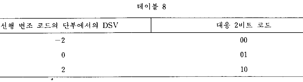
제1도에서, 8비트 디지탈 데이타(1)은 엔코더(2)에 의해 14비트 디지탈 변조 코드로 변환된다. 엔드 패턴(end pattern) 판단부(3)는 14비트 디지탈 변조 코드의 마지막 6비트의 엔드 패턴을 테이블 9에 있는 4비트 코드로 변환시킨다(변조 코드의 마지막 8비트가 테이블 9에 주어져 있을지라도 단지 마지막 6비트만이 고려되어야만 한다). CDS 계산부(5)는 제공된 14비트 디지탈 변조 코드의 CDS를 계산하고 계산된 CDS를 테이블 7에 있는 3비트 코드로 변환시킨다. DSV 계산부(4)는 선행 14비트 디지탈 변조 코드의 단부에서 현행 14비트 디지탈 변조 코드의 CDS를 DSV에 가산하여 새로운 DSV를 만들어내며, 이 새로운 DSV를 테이블 8에 있는 2비트 코드로 변환시킨다.In FIG. 1, 8-bit
병렬-직렬 변환기(8)는 14비트 디지탈 변조 코드를 클럭 신호(9)와 동기되는 직렬 신호로 변환시킨다. 기록부(10)는 자기테이프 등과 같은 기록 매체상에 병렬-직렬 변환기(8)로부터 생성된 직렬 변조 신호를 기록한다.The parallel-to-


X : 무관심 비트X: indifference bit
CDS 계산부(5)의 출력 코드는 DSV 계산부(4)에 공급된다.The output code of the
DSV 계산부(4)는 코드를 래치(6)를 경유해 엔코더(2)에 공급한다. 엔드 패턴 판단부(3)는 코드를 래치(7)를 경유해 엔코더(2)에 제공한다.The
다음에는, 각각의 입력된 8비트 디지탈 데이타에 대응하는 14비트 디지탈 변조 코드를 선택하는 방법에 대해 설명하기로 한다.Next, a method of selecting a 14-bit digital modulation code corresponding to each input 8-bit digital data will be described.
먼저, 각각의 8비트 디지탈 데이타에 대해 4개까지의 14비트 디지탈 변조 코드를 선택하는 방법이 설명된다. 14비트 디지탈 변조 코드는,First, a method of selecting up to four 14-bit digital modulation codes for each 8-bit digital data is described. 14-bit digital modulation code,
(a) 214비트 디지탈 코드중에서, 연속한 동일 비트수가 제 1의 6비트에서는 5이하이고 제 2 비트에서 제 13비트까지는 2-7이고 마지막 7비트에서는 6이하이며 선택된 디지탈 코드의 CDS(코드 워드 디지탈 합)의 절대값은 4이하인 디지탈 코드를 선택하고, 이러한 선택 절차를 계속하는 절차,(a) Of 2 14- bit digital codes, the same number of consecutive bits is 5 or less in the first 6 bits, 2-7 in the second to 13 bits, 6 or less in the last 7 bits, and the CDS of the selected digital code (code Select a digital code whose absolute value of the word digital sum) is 4 or less, and continue this selection process,
(b) 절차(a)에서 선택된 14비트 디지탈 코드중에서 제1비트가 “0”이고 CDS의 값이 0인 디지탈 코드를 선택하고, 그 디지탈 코드를 1그룹으로 만들기 위해 선택된 14비트 디지탈 코드와 그것의 반전 코드를 쌍으로 하고, 또는 절차(a)에서 선택된 14비트 디지탈 코드중에서, 제1비트가 “1”이고 CDS의 값이 +2 또는 +4인 디지탈 코드를 선택하고, 선택된 14비트 디지탈 코드와 그의 반전 코드를 결합하고, 4디지탈 코드를 1그룹으로 만들기 위해 두개의 14비트 디지탈 코드와 상기 절차에서 선택된 한쌍의 14비트 디지탈 코드를 더 포함하고, 이러한 선택 절차를 반복하는 절차,(b) From the 14-bit digital code selected in the procedure (a), select the digital code whose first bit is "0" and the value of the CDS is 0, and the 14-bit digital code selected to make the digital code into one group and that Pairs the inversion codes of or, from the 14-bit digital code selected in the procedure (a), selects a digital code whose first bit is "1" and the value of the CDS is +2 or +4, and selects the selected 14-bit digital code. Further comprising two 14-bit digital codes and a pair of 14-bit digital codes selected in the above procedure to combine and the inversion code thereof and to group the four digital codes into one group, and repeating this selection procedure,
(c) 절차(a)에서 선택된 14비트 디지탈 코드중에서, 제 1 비트가 “0”이며 CDS의 값이 +2인 디지탈 코드를 선택하고, 제1비트가 “1”이고 CDS의 값이 +2 또는 +4인 또 하나의 다른 디지탈 코드를 선택하고, 4디지탈 코드를 1그룹으로 만들기 위하여 두개의 선택된 14비트 디지탈 코드와 그의 반전 코드를 결합시키고, 이러한 선택 절차를 반복하는 절차,(c) Of the 14 bit digital codes selected in the procedure (a), select the digital code whose first bit is "0" and the value of the CDS is +2, and the first bit is "1" and the value of the CDS is +2. Or selecting another another digital code of +4, combining the two selected 14-bit digital codes with their inversion code to make a group of 4 digital codes, and repeating this selection procedure,
(d) 절차(a)에서 선택된 14비트 디지탈 코드중에서, 제 1 비트가 “0”이고 CDS의 값이 +4인 디지탈 코드를 선택하고, 제1비트가 “1”이고 CDS의 값이 +2 인 또 하나의 다를 디지탈 코드를 선택하고, 4디지탈 코드를 1그룹으로 만들기 위하여 두개의 서택된 14비트 디지탈 코드와 그의 반전 코드를 결합하고, 이러한 선택 절차를 반복하는 절차 및,(d) Of the 14 bit digital codes selected in the procedure (a), select the digital code whose first bit is "0" and the value of the CDS is +4, and the first bit is "1" and the value of the CDS is +2. Selecting another different digital code, combining two selected 14-bit digital codes with their inversion codes to make a group of 4 digital codes, and repeating this selection procedure;
(e) 상기 절차에서 형성된 그룹중에서 256그룹을 14비트 디지탈 변조 코드로서 선택하는 절차에 의해 선택된다.(e) is selected by the procedure of selecting 256 groups as 14-bit digital modulation codes from the groups formed in the above procedure.
다음에는 입력된 8비트 데이타에 대응하는 14비트 디지탈 변조 코드(현행 변조 코드)의 선택 절차에 대해 설명하기로 한다.Next, a procedure of selecting a 14-bit digital modulation code (current modulation code) corresponding to the input 8-bit data will be described.
먼저, 선행 변조 코드의 단부에서 DSV가 계산되고, 선행 변조 코드의 엔드 패턴은 테이블 9에 도시된 12개의 엔드 패턴중 하나로서 결정된다.First, the DSV is calculated at the end of the preceding modulation code, and the end pattern of the preceding modulation code is determined as one of the twelve end patterns shown in Table 9.
후속해서, 현행 14비트 디지탈 변조 코드는 8비트 데이타, 선행 변조 코드의 단부에서의 DSV 및 선행 변조 코드의 엔드 패턴에 응답하여 엔코더(2)에 의해 선택된다.Subsequently, the current 14-bit digital modulation code is selected by the
좀더 상세하게는, 현행 14비트 디지탈 변조 코드를 선택하는데 다음의 단계들이 취해진다.More specifically, the following steps are taken to select the current 14-bit digital modulation code.
(1) 다음의 조건을 만족하는 14비트 디지탈 변조 코드는 테이블 4 및 5에서 선택된다 : (a) 선행 14비트 디지탈 변조 코드와의 결합부에서 연속한 동일 비트수는 2개의 내지 7개이고 : (b) 디지탈 변조 코드의 단부에서의 DSV(이하 엔드 DSV라 함)의 절대값은 2와 같거나 2보다 작다.(1) 14-bit digital modulation codes satisfying the following conditions are selected from Tables 4 and 5: (a) The number of consecutive identical bits in the combination with the preceding 14-bit digital modulation code is two to seven: ( b) The absolute value of DSV (hereinafter referred to as end DSV) at the end of the digital modulation code is equal to or less than 2.
(2) 2이상의 14비트 디지탈 변조 코드가 단계(1)에서 선택될때, 엔드 DSV의 최소 절대값을 주는 14비트 디지탈 변조 코드가 선택된다.(2) When two or more 14-bit digital modulation codes are selected in step (1), a 14-bit digital modulation code giving the minimum absolute value of the end DSV is selected.
(3) 2이상의 14비트 디지탈 변조 코드가 단계(2)에서 아직 선택되고 있을때, 14비트 디지탈 변조 코드는 변조 코드의 비트 DSV를 계산하고, 절대값이 각각의 변조 코드에 대해서 최소인 비트 DSV를 판정하고, 절대값이 최소인 비트 DSV들중에서도 최소의 비트 DSV를 포함하는 코드를 선택하므로써 선택된다.(3) When two or more 14-bit digital modulation codes are still selected in step (2), the 14-bit digital modulation code calculates the bit DSV of the modulation code and returns the bit DSV whose absolute value is the minimum for each modulation code. Is determined by selecting a code including the smallest bit DSV among the bit DSVs with the smallest absolute value.
(4) 2이상의 14비트 디지탈 변조 코드가 단계(3)에서 더 발견될때, 14비트 디지탈 변조 코드는 각각의 변조 코드의 비트 DSV의 최대 절대값을 구하고, 최대 절대값이 6 또는 그 이하인 비트 DSV를 포함하는 코드를 선택하므로써 선택된다.(4) When two or more 14-bit digital modulation codes are further found in step (3), the 14-bit digital modulation code finds the maximum absolute value of the bit DSV of each modulation code, and the bit DSV whose maximum absolute value is 6 or less. It is selected by selecting a code containing.
(5) 2이상의 변조 코드가 단계(4)에서 아직 발견될때, 선행 14비트 디지탈 변조 코드와의 결합부에서 연속한 동일 비트수가 6 또는 그 이하라는 조건을 만족하는 14비트 디지탈 변조 코드가 선택된다.(5) When two or more modulation codes are still found in step (4), a 14-bit digital modulation code is selected which satisfies the condition that the number of consecutive identical bits in the combination with the preceding 14-bit digital modulation code is 6 or less. .
(6) 단계(4)에서 선택된 코드중 어떤 변조 코드도 단계(5)를 만족하지 못할때, 또는 2이상의 변조 코드가 단계(5)를 만족하지 못할때는, 상기 변조 코드내의 연속할 동일 비트가 6 또는 그 이하인 조건을 만족하는 14비트 디지탈 변조 코드가 선택된다.(6) When no modulation code of the code selected in step (4) satisfies step (5), or when two or more modulation codes do not satisfy step (5), the same consecutive bits in the
(7) 단계(4)에서 선택된 코드중 어떤 변조 코드도 단계(5) 및 (6)을 만족하지 못할때, 또는 단계(5)에서 선택된 변조 코드 어느것도 단계(6)를 만족하지 못할때, 또는 2이상의 변조 코드가 단계(6)에서 더 발견될 때는, 다음의 단계들이 취해진다.(7) when any of the modulation codes selected in step (4) do not satisfy steps (5) and (6), or when none of the modulation codes selected in step (5) satisfy step (6), Or when two or more modulation codes are found further in
(7a) 변조 코드의 엔드 DSV가 -2일때, 코드 우선순위(테이블 10에서 작은 수일수록 순위가 높음)가 테이블 10에 따라서 선택된다. 비슷한 식으로, 변조 코드의 엔드 DSV가 +2일때, 코드 우선순위는 테이블 11에 따라서 선택된다.(7a) When the end DSV of the modulation code is -2, the code priority (the smaller the number in Table 10, the higher the rank) is selected according to Table 10. Similarly, when the end DSV of the modulation code is +2, the code priority is selected according to Table 11.
(7b) 동일한 가장 빠른 우선순위에 속하는 2이상의 변조 코드가 단계(7a)에서 발견될때, 그들 모두는 일시에 선택된다. 엔드 DSV가 0일때, 마지막 6비트가 변조 코드에서 “…111111” 또는 “…000000”이 아님을 만족하는 변조 코드가 선택된다.(7b) When two or more modulation codes belonging to the same fastest priority are found in step 7a, they are all selected at one time. When the end DSV is zero, the last 6 bits indicate the “…” in the modulation code. 111111 ”or“… The modulation code that satisfies not 000000 ”is selected.
(8) 단계(4)에서 선택된 변조 코드 어느것도 단계(5), (6) 및 (7)을 만족하지 못할때, 또는 단계(5)에서 선택된 변조 코드 어느것도 단계(6) 및 (7)을 만족하지 못할때, 또는 단계(6)에서 선택된 변조 코드 어느것도 단계(7)를 만족하지 못할때, 또는 2이상의 변조 코드가 단계(7)에서 더 발견될때는 비트 DSV의 최대 절대값중 최소의 비트 DSV를 포함하는 변조 코드가 선택된다.(8) when none of the modulation codes selected in step (4) satisfies steps (5), (6) and (7), or none of the modulation codes selected in step (5) are steps (6) and (7) Is not satisfied, or if none of the modulation codes selected in step (6) satisfy step (7), or when two or more modulation codes are found in step (7), the minimum of the maximum absolute value of the bit DSV. The modulation code containing bit DSV of is selected.
(9) 2이상이 변조 코드가 단계(8)에서 아직 발견될대, 최소 절대값이 변조 코드의 비트 열(bit string)에서 가장 빠르게 나타나는 비트 DSV를 포함하는 변조 코드가 선택된다.(9) When two or more modulation codes are still found in
(10) 2이상의 변조 코드가 단계(9)에서 더 발견될때, 선행 변조 코드와의 결합부 다음에서 비트가 가장 빠르게 반전되는 변조 코드가 선택된다.(10) When more than two modulation codes are found in

X : 무관심 비트X: indifference bit

X : 무관심 비트X: indifference bit
그렇게 선택된 14비트 디지탈 변조 코드는 병렬-직렬 변환기(8)에 공급된다. 병렬-직렬 변환기(8)에 들어간 변조 코드는 클럭(9)와 동기되어 직렬로 판독된다. 여기서 14비트 디지탈 변조 코드는 자기테이프 등과 같은 기록 매체에 기록된다.The 14-bit digital modulation code so selected is supplied to the parallel-to-
한편, 엔코더(2)에 의해 선택된 14비트 디지탈 변조 코드는 DSV 계산부(4)와 엔드 패턴 판단부(3)에 제공된다. DSV 계산부(4)는 새로운 DSV를 얻기 위해 현행 변조 코드의 CDS를 선행 변조 코드의 단부에 있는 DSV에 가산한다. 이 새로운 DSV는 테이블 8에 따라서 2비트 코드로 변환되며 래치(6)를 통해 엔코더(2)에 공급된다. 엔드 패턴 판단부(3)는 14비트 변조 코드의 마지막 6비트를 테이블 9에 따라 4비트로 변환시켜, 이 4비트 코드를 래치(7)를 거쳐 엔코더(2)에 공급한다.On the other hand, the 14-bit digital modulation code selected by the
상기 절차는 모든 8비트 입력 데이타에 대해 반복된다. 그래서 14비트 디지탈 변조 코드 열이 얻어지고, 여기서 연속한 동일 비트수는 2-7로 제한되고 DSV의 절대값은 7 또는 그 이하로 제한된다.The procedure is repeated for all 8 bit input data. Thus a 14-bit digital modulation code sequence is obtained, where the number of consecutive identical bits is limited to 2-7 and the absolute value of the DSV is limited to 7 or less.
제2도는 디코딩 회로의 한 예를 보여주고 있다. 제2도에서, 도면 부호 11은 재생부를 가리키고, 12는 동기 신호 검출기를 가리키고, 13은 직렬-병렬 변환기를 가리키고, 14는 디코더를 가리킨다. 디코딩 회로에 의한 디코딩 절차가 이하 설명된다.2 shows an example of a decoding circuit. In Fig. 2,
재생부(11)에 의해 재생된 직렬 변조 코드는 동기 신호 검출기(12)와 직렬-병렬 변환기(13)에 공급된다. 동기 신호 검출기(12)는 동기 블록의 초기에 삽입된 동기 신호를 검출하여, 그것을 직렬-병렬부(13)에 공급한다. 동기 신호는 각각의 14비트 디지탈 변조 코드와 동기시키는데 이용된다. 동기 신호 검출기(12)로부터의 동기 신호를 이용하여, 병렬-직렬 변환기(13)는 14비트 디지탈 변조 코드를 병렬 14비트 디지탈 변조 코드로 변환시켜, 그것을 디코더(14)에 공급한다. 디코더(14)는 ROM을 이용함으로써 14비트 디지탈 변조 코드를 대응하는 8비트 데이타를 디코드 한다.The serial modulation code reproduced by the reproducing
다음에는 제1도의 엔코더(2)로부터 발생된 14비트 디지탈 변조 코드에 대해 설명하기로 한다. 8비트 코드로부터 변환된 14비트 디지탈 변조 코드는 다음 필요 조건을 만족한다 :Next, the 14-bit digital modulation code generated from the
(1) 제1의 6비트에서 연속한 동일 비트수는 5 또는 그 이하이다.(1) The same number of consecutive bits in the first 6 bits is 5 or less.
(2) 제2비트에서 제13비트까지에 포함되어 있는 연속한 동일 비트수는 2-7이다.(2) The number of consecutive identical bits included in the second to thirteenth bits is 2-7.
(3) 마지막 7비트에 포함되어 있는 연속한 동일 비트수는 6 또는 그 이하이다.(3) The number of consecutive identical bits included in the last 7 bits is 6 or less.
(4) 변조 코드의 CDS의 절대값은 4 또는 그 이하이다.(4) The absolute value of the CDS of the modulation code is 4 or less.
상기 필요 조건(1) 내지 (4)를 만족하는 변조 코드의 엔드 패턴은 다음 12아이템 (A)-(M)으로서 요약 된다.The end pattern of the modulation code that satisfies the above requirements (1) to (4) is summarized as the following 12 items (A)-(M).
(A) … … … 110(A). … … 110
(B) … … … 1100(B). … … 1100
(C) … … … 11000(C)... … … 11000
(D) … … … 110000(D)…. … … 110000
(E) … … … 1100000(E). … … 1100000
(F) … … … 11000000(F)… … … 11000000
(G) … … … 001(G)… … … 001
(H) … … … 0011(H)... … … 0011
(J) … … … 00111(J)… … … 00111
(K) … … … 001111(K)… … … 001111
(L) … … … 0011111(L)… … … 0011111
(M) … … … 00111111(M)... … … 00111111
변조 코드(A)-(M)에 이어지는 변조 코드의 시작은 다음의 아이템중 하나이다.The start of the modulation code following the modulation codes (A)-(M) is one of the following items.
먼저, 변조 코드(A)에 이어지는 변조 코드의 시작은 다음의 5 아이템(A1)-(A5)중 하나이다First, the start of the modulation code following the modulation code A is one of the following five items A1-A5.
(A1) 011 … … … …(A1) 011... … … …
(A2) 0011 … … … …(A2) 0011... … … …
(A3) 00011 … … …(A3) 00011... … …
(A4) 000011 … … …(A4) 000011... … …
(A5) 0000011 … …(A5) 0000011... …
둘째로, 변조 코드(B)에 이어지는 변조 코드의 시작은 다음의 9 아이템(B1)-(B9)중 하나이다.Secondly, the start of the modulation code following the modulation code B is one of the following nine items B1-B9.
(B1) 011 … … … …(B1) 011... … … …
(B2) 0011 … … … …(B2) 0011... … … …
(B3) 00011 … … …(B3) 00011... … …
(B4) 000011 … … …(B4) 000011... … …
(B5) 0000011 … …(B5) 0000011... …
(B6) 1100 … … … …(B6) 1100... … … …
(B7) 11100 … … …(B7) 11100. … …
(B8) 111100 … … …(B8) 111100... … …
(B9) 1111100 … … …(B9) 1111100... … …
변조 코드(C)에 이어지는 변조 코드의 시작은 다음의 8 아이템(C1)-(C8)중 하나이다.The start of the modulation code following the modulation code C is one of the following eight items C1-C8.
(C1) 011 … … … …(C1) 011... … … …
(C2) 0011 … … … …(C2) 0011... … … …
(C3) 00011 … … …(C3) 00011... … …
(C4) 000011 … … …(C4) 000011... … …
(C5) 1100 … … … …(C5) 1100... … … …
(C6) 11100 … … …(C6) 11100. … …
(C7) 111100 … … …(C7) 111100... … …
(C8) 1111100 … …(C8) 1111100... …
변조 코드(D)에 이어지는 변조 코드의 시작은 다음의 7 아이템(D1)-(D7) 중 하나이다.The start of the modulation code following the modulation code D is one of the following seven items D1-D7.
(D1) 011 … … … …(D1) 011... … … …
(D2) 0011 … … … …(D2) 0011... … … …
(D3) 00011 … … …(D3) 00011... … …
(D4) 1100 … … …(D4) 1100... … …
(D5) 11100 … … … …(D5) 11100. … … …
(D6) 111100 … … …(D6) 111100... … …
(D7) 1111100 … … …(D7) 1111100... … …
변조 코드(E)에 이어지는 변조 코드의 시작은 다음의 6 아이템(E1)-(E6) 중 하나이다.The start of the modulation code following the modulation code E is one of the following six items E1-E6.
(E1) 011 … … … …(E1) 011... … … …
(E2) 0011 … … … …(E2) 0011... … … …
(E3) 1100 … … … …(E3) 1100... … … …
(E4) 11100 … … …(E4) 11100. … …
(E5) 111100 … … …(E5) 111100... … …
(E6) 1111100 … …(E6) 1111100... …
변조 코드(F)에 이어지는 변조 코드의 시작은 다음의 5 아이템(F1)-(F5)중 하나이다.The start of the modulation code following the modulation code F is one of the following five items F1-F5.
(F1) 011 … … … …(F1) 011... … … …
(F2) 1100 … … … …(F2) 1100. … … …
(F3) 11100 … … …(F3) 11100. … …
(F4) 111100 … … …(F4) 111100... … …
(F5) 1111100 … …(F5) 1111100. …
변조 코드(G)에 이어지는 변조 코드의 시작은 변조 코드(A1)-(A5)의 반전 패턴중 하나이다.The start of the modulation code following modulation code G is one of the inversion patterns of modulation codes A1-A5.
변조 코드(H)에 이어지는 변조 코드의 시작은 변조 코드(B1)-(B9)의 반전 패턴이다.The start of the modulation code following the modulation code H is the inversion pattern of modulation codes B1-B9.
변조 코드(J)에 이어지는 변조 코드의 시작은 변조 코드(C1)-(C8)의 반전 패턴이다.The start of the modulation code following modulation code J is the inversion pattern of modulation codes C1-C8.
변조 코드(K)에 이어지는 변조 코드의 시작은 변조 코드(D1)-(D7)의 반전 패턴이다.The start of the modulation code following modulation code K is the inversion pattern of modulation codes D1-D7.
변조 코드(L)에 이어지는 변조 코드의 시작은 변조 코드(E1)-(E6)의 반전 패턴이다.The start of the modulation code following modulation code L is the inversion pattern of modulation codes E1-E6.
변조 코드(M)에 이어지는 변조 코드의 시작은 변조 코드(F1)-(F5)의 반전 패턴이다.The start of the modulation code following the modulation code M is the inversion pattern of modulation codes F1-F5.
필요 조건(1)-(5)를 만족하는 변조 코드의 수는 테이블 1 및 2에 도시되어 있다. 코드 “10000000111111”(CDS=0), 및 코드 “01111111000000”(CDS=0)는 그 수에서 제외되어 있다.The number of modulation codes that satisfy the requirements (1)-(5) is shown in Tables 1 and 2. The code "10000000111111" (CDS = 0) and the code "01111111000000" (CDS = 0) are excluded from the number.


CDS![]()
![]()
![]()
![]()
변조 코드(A)-(M)중 하나에 이어질 수 있는 변조 코드수는 테이블 3에서 볼 수 있다.The number of modulation codes that can follow one of the modulation codes (A)-(M) can be seen in Table 3.
예로서, “…00111111”로 종료되는 변조 코드의 CDS는 “2” 또는 “4”이다. 따라서, 변조 코드의 엔드 DVS는 “0”또는 “2”의 값을 취하며, 그러므로 상기 이어지는 변조 코드는 CDS![]()
![]()
비슷한 식으로, “…11000000”로 종료되는 변조 코드의 CDS는 “-2”또는 “-4”이다. 따라서, 변조 코드의 엔드 DSV는 “0” 또는 “-2”의 값을 취하며, 그러므로 상기 이어지는 변조 코드는 CDS![]()
![]()

제4도는 CDS![]()
![]()
![]()
![]()
테이블 4 및 5는 8비트 데이타와 변조 코드 사이의 대응 관계를 보여주고 있다. 즉 테이블 4는 CDS![]()
![]()
![]()
![]()


테이블(4)의 5(B)에 있는 변조 코드는 엔드 DSV를 향상시키기 위해 테이블 12에 도시되는 대로 바뀔수 있다. 즉 5(B)에서 CDS=0인 6개의 변조 코드는 2개 감소되어 4개로 되고, CDS=2인 사용되지 않았던 두개의 새로운 변조 코드가 부가된다.The modulation code in 5 (B) of table 4 can be changed as shown in table 12 to improve the end DSV. That is, at 5 (B), six modulation codes with CDS = 0 are reduced to two, and four new modulation codes with CDS = 2 are added.

CDS=2인 변조 코드를 선택하면, 선행하는 변조 코드의 엔드 DSV가 -2이고, 선행 코드의 마지막 비트 패턴이 패턴 “01”, “100”, “1000”, “10000”, “100000”, 및 “1000000”중에서 임의의 하나이고, 신호 데이타가 250 또는 251일때, 선택된 변조 코드 끝에서의 엔드 DSV를 0으로 조정할 수 있다.If a modulation code with CDS = 2 is selected, the end DSV of the preceding modulation code is -2, and the last bit pattern of the preceding code is the patterns “01”, “100”, “1000”, “10000”, “100000”, And "1000000", and when the signal data is 250 or 251, the end DSV at the end of the selected modulation code can be adjusted to zero.
테이블 4의 5(B)에 있는 코드들의 반전 코드인 테이블 5의 5(C)에 있는 변조 코드 역시 테이블 B에 도시되어 있는 대로 바뀔수 있다.The modulation code in 5 (C) of Table 5, which is the inverse code of the codes in 5 (B) of Table 4, can also be changed as shown in Table B.

테이블 4 및 12에 사용되지 않은 CDS=4인 변조 코드는 테이블 4, 또는 테이블 4 및 12에 있는 변조 코드대신 사용될 수 있다. 선행 변조 코드의 단부에 있는 엔드 DSV가 -2일때 CDS=4인 변조 코드를 선택하면, 선택된 변조 코드에 있는 특정 비트에서 비트 DSV가 0을 확실히 취할 수 있기 때문에, 선택된 변조 코드의 비트 DSV가 향상된다.Modulation codes with CDS = 4 not used in Tables 4 and 12 may be used instead of the modulation codes in Table 4, or Tables 4 and 12. Selecting a modulation code with CDS = 4 when the end DSV at the end of the preceding modulation code is -2 improves the bit DSV of the selected modulation code, since the bit DSV can certainly take zero at a particular bit in the selected modulation code. do.
테이블 4 및 12에 있는 코드의 반전 패턴인 테이블 5 및 13에 있는 변조 코드는 상기와 비슷한 식으로 바뀔 수 있어, 그 결과도 유사한 향상이 있게 된다.The modulation codes in Tables 5 and 13, which are the inversion patterns of the codes in Tables 4 and 12, can be changed in a similar manner as above, resulting in similar improvements.
테이블 4 및 5에 있는 8비트 데이타에 대응하게 특정된 변조 코드는 한가지 예이다. 그러므로 변조 코드와 8비트 코드의 조합은 변경할 수 있다.The modulation code specified corresponding to 8-bit data in Tables 4 and 5 is one example. Therefore, the combination of modulation code and 8-bit code can be changed.
선행 변조 코드의 엔드 패턴에 따라 나타나도록 되어 있는 변조 코드형 태들이 테이블 5에 도시되어 있다.Modulation code types that are intended to appear according to the end pattern of the preceding modulation code are shown in Table 5.

테이블 6에서, “0”마크는 변조 코드가 허용됨을 가리키고, “*”는 선형 코드의 엔드 패턴이 “…11000000”일때 CDS≥0인 변조 코드가 선택되며, 선행 변조 코드의 엔드 패턴이 “…00111111”일때 CDS![]()
![]()
예로, 선행 변조 코드의 엔드 패턴이 “…11000”일때 그리고 선행 변조 코드의 엔드 DSV가 -2일때, 테이블 4에서의 클라스 1(A), 2(A), 3(A), 4(A), 2(B), 3(B), 4(B) 및 5(B)의 변조 코드는 선택될 현행 변조 코드가 CDS![]()
![]()
이 경우에, 현행 8-비트 데이타가 “166”이라고 가정하자. 그러면, 테이블 4에 있는 두개의 가능한 변조 코드 “00111110011001”(CDS=2 ; 2(A)) 및 “11001111100110”(CDS=4, 2(B))가 선택된다 : 선행 변조 코드의 엔드 DSV와 현행 변조 코드의 CDS는 현행 변조 코드의 엔드 DSV를 얻기 위해 합쳐지고 : 보다 적은 엔드 DSV를 제공하는 변조 코드 즉 ”00111110011001”(CDS=2)가 선택된다. 결과적인 엔드 DSV는 0이고 이는 직류 성분이 제거되었음을 가리킨다.In this case, assume that the current 8-bit data is "166". Then, two possible modulation codes “00111110011001” (CDS = 2; 2 (A)) and “11001111100110” (CDS = 4, 2 (B)) in Table 4 are selected: the end DSV of the preceding modulation code and the current The CDS of the modulation code is combined to obtain the end DSV of the current modulation code: The modulation code that provides less end DSV, i.e., " 00111110011001 " (CDS = 2), is selected. The resulting end DSV is zero, indicating that the direct current component has been removed.
제3a도는 자기테이상에 기록된 사인파가 재생될때의 CNR(캐리어 대 잡음비) 특성을 보여주고 있고, 제3b도는 랜덤 8비트 데이타가 변조기에 입력될때 변조기의 출력 단자에서의 전력 스펙트럼을 보여주고 있으며, 제3c도는 랜덤 8비트 데이타가 스크램블된 NRZ 변조기에 입력될때 스크램블된 NRZ 변조기의 출력 단자에서의 스크램블된 NRZ의 전력 스펙트럼을 보여주고 있다. 이들 도면으로부터, 본 발명의 디지탈 변조 방법에 따라서 전력 스펙트럼은 직류 성분을 포함하지 않으며 높은 CNR이 얻어지는 기록-재생 대역폭내에 포함됨을 알수 있다. 결과적으로, 자기테이프와 헤드 시스템의 기록-재생 특성은 효율적으로 이용될 수 있다. 더구나, 본 발명에 따른 디지탈 변조 방법의 변조 코드의 최소 자화 전이폭은 스크램블된 NRZ의 최소 자화 전이폭의 1.14배이다. 결과적으로 코드간 간섭이 감소된다.FIG. 3a shows the carrier-to-noise ratio (CNR) characteristics of the sine wave recorded on the magnetic tape. FIG. 3b shows the power spectrum at the output terminal of the modulator when random 8-bit data is input to the modulator. Figure 3c shows the power spectrum of the scrambled NRZ at the output terminal of the scrambled NRZ modulator when random 8-bit data is input to the scrambled NRZ modulator. From these figures, it can be seen that according to the digital modulation method of the present invention, the power spectrum does not include a direct current component and is included in a recording-reproducing bandwidth where a high CNR is obtained. As a result, the recording-reproducing characteristics of the magnetic tape and the head system can be used efficiently. Moreover, the minimum magnetization transition width of the modulation code of the digital modulation method according to the present invention is 1.14 times the minimum magnetization transition width of the scrambled NRZ. As a result, inter-code interference is reduced.
상술한 바와같이 상기 실시예는 변조 코드열에서 연속한 동일 비트의 수를 2-7로 제한하고 있다. 결과적으로, 최소 자화 전이폭은 1.14T(=(2×8)/14)이다. 여기서 T는 데이타의 주기이다. 최대 자화 전이폭은 4.00(=(7×8)T/14이고, DR은 1.14(=(2×8)/14)이고, 최대 자화 전이폭과 최소 자화 전이폭의 비는 3.5이다. 따라서, 자기 기록의 비트 에러율이 감소 되고, 고밀도 기록이 가능해진다. 또한, 애지무스 기록 및 고질 오버 기록도 가능해진다.As described above, the embodiment limits the number of consecutive identical bits in the modulation code string to 2-7. As a result, the minimum magnetization transition width is 1.14T (= (2 × 8) / 14). Where T is the period of data. The maximum magnetization transition width is 4.00 (= (7 × 8) T / 14, DR is 1.14 (= (2 × 8) / 14), and the ratio of the maximum magnetization transition width and the minimum magnetization transition width is 3.5. The bit error rate of magnetic recording is reduced, high density recording is possible, and azimuth recording and high quality over recording are also possible.
또한, 상기 실시예는 변조 코드의 CDS의 절대값을 4 또는 그 이하로 제한하고, 선행 변조 코드의 단부에 있는 DSV와 선행 코드의 엔드 패턴에 따라 각각의 8비트 데이타에 4개 까지의 변조 코드를 할당하여, 최소 절대값을 제공하는 엔드 DSV를 갖는 변조 코드를 선택한다. 결과적으로, 각각의 변조 코드의 단부에서 계산되는 엔드 DSV의 절대값은 2이내이며, 변조 코드의 각각의 비트에서 계산되는 비트 DSV의 절대값은 7이내이다. 그래서, 직류 성분은 효율적으로 제거되며, 그러므로 변조 코드의 전송은 직류 성분을 통과 시키지 않는 로터리 변환기를 이용하므로써 가능해진다.Further, the embodiment limits the absolute value of the CDS of the modulation code to 4 or less, and up to four modulation codes for each 8-bit data depending on the DSV at the end of the preceding modulation code and the end pattern of the preceding code. Select the modulation code with the end DSV that provides the minimum absolute value. As a result, the absolute value of the end DSV calculated at the end of each modulation code is less than 2, and the absolute value of the bit DSV calculated at each bit of the modulation code is less than 7. Thus, the direct current component is efficiently removed, and therefore the transmission of the modulation code is made possible by using a rotary converter which does not pass the direct current component.
[[B] 제 2 실시예][B] Second Embodiment
제6도는 본 발명의 디지탈 변조 방법의 제 2 실시예에 따라 디지탈 변조를 실행하기 위한 디지탈 변조 장치를 보여주는 블록 다이어그램이다. 제6도에서, 8비트 디지탈 데이타(1)는 엔코더(2)에 의해 14비트 디지탈 변조 코드로 변환된다. 엔드 패턴 판단부(3)는 14비트 디지탈 변조 코드의 마지막 5비트의 엔드 패턴을 테이블 21에 있는 4비트 코드로 변환시킨다(변조 코드의 마지막 7비트가 테이블(21)에 주어져 있을지라도, 단지 마지막 5비트만이 고려되고 있다). CDS계산부(5)는 공급된 14비트 디지탈 변조 코드의 CDS를 계산하고, 그 결과의 CDS를 테이블 20에 있는 3비트 코드로 변환시킨다. DSV 계산부(4)는 현행 14비트 디지탈 변조 코드의 CDS를 선행 14비트 디지탈 변조 코드의 단부에 있는 DSV에 가산시켜 새로운 DSV를 산출해내고, 이 뉴 DSV를 테이블 20에 있는 3비트 코드로 변환시킨다.6 is a block diagram showing a digital modulation device for performing digital modulation according to the second embodiment of the digital modulation method of the present invention. In FIG. 6, 8-bit
병렬-직렬 변환기(8)는 14비트 디지탈 변조 코드를 클럭 신호 9와 동기되어 직렬 신호로 변환시킨다. 기록부(10)는 병렬-직렬 변환기(8)로부터 생성된 직렬 변조 신호를 자기테이프 등과 같은 기록 매체에 기록한다.Parallel-to-

X : 무관심 비트X: indifference bit
CDS 계산부(5)에 의해 테이블 20에 있는 3비트 코드로 변환된 도출된 CDS는 DSV 계산부(4)에 공급된다.The derived CDS, which is converted by the
DSV 계산부(4)는 도출된 DSV를 테이블 20에 있는 3비트 코드로 변환시켜 이 코드를 래치(6)를 통해 엔코더(2)에 공급한다. 엔드 패턴 판단부(3)는 마지막 5비트를 테이블 21에 있는 4비트 코드로 변환시켜, 이 코드를 래치(7)를 통해 엔코더(2)에 공급한다.The
다음에는 각각의 입력된 8비트 디지탈 데이타에 대응하는 14비트 디지탈 변조 코드를 선택하는 방법이 설명된다.Next, a method of selecting a 14-bit digital modulation code corresponding to each input 8-bit digital data is described.
먼저, 각각의 8비트 디지탈 데이타에 대해 14비트 디지탈 변조 코드를 4개까지 선택하는 방법이 설명된다.First, a method of selecting up to four 14-bit digital modulation codes for each 8-bit digital data is described.
14비트 디지탈 변조 코드는, (a) 21414비트 디지탈 코드중에서, 연속한 동일 비트수가 제1의 7비트에서 6 또는 그 이하이고 제 2 비트에서 제13비트까지는 2-7이고, 마지막 6비트에서는 5 또는 그 이하인 디지탈 코드를 선택하고, 이러한 선택 절차를 반복하는 절차, (b) 절차(a)에서 선택된 14비트 디지탈 코드중에서, 제1비트가 “0”이고, CDS의 절대값이 6 또는 그 이하인 디지탈 코드를 선택하고, 이러한 선택 절차를 반복하는 절차, (c) 절차(a)에서 선택된 14비트 디지탈 코드 중에서, CDS의 절대값이 4 또는 그 이하인 디지탈 코드를 선택하고, 선택하고, 이러한 선택 절차를 반복하는 절차, (d) 절차(b)에서 선택된 14비트 디지탈 코드중에서, CDS값이 0인 디지탈 코드를 선택하고, 2디지탈 코드를 한 그룹으로 만들기 위하여 선택된 14비트 디지탈 코드와 그의 반전 코드를 쌍으로 하고, 이러한 선택 절차를 반복하는 절차, (e) 절차(b)에서 선택된 14비트 디지탈 코드중에서, CDS의 값이 +2, +4 또는 +6인 디지탈 코드를 선택하고, 절차(c)에서 선택된 14비트 디지탈 코드중에서 CDS의 값이 +2 또는 +4인 디지탈 코드를 선택하고, 4디지탈 코드를 한 그룹으로 만들기 위해 두개의 선택된 14비트 디지탈 코드와 그의 반전 코드를 결합하고, 이러한 선택 절차를 반복하는 절차, (f) 14비트 디지탈 변조 코드로서 상기 절차에서 형성된 그룹들중에서 256그룹을 선택하는 절차에 의해 선택된다.The 14-bit digital modulation code is (a) of 2 14 14-bit digital codes, the number of consecutive identical bits being 6 or less in the first 7 bits and 2-7 in the second to 13 bits, and the last 6 bits. Selects a digital code of 5 or less, repeats this selection procedure, (b) of the 14-bit digital codes selected in step (a), the first bit is “0” and the absolute value of the CDS is 6 or Selecting a digital code that is less than or equal to and repeating this selection procedure, (c) selecting and selecting a digital code having an absolute value of 4 or less from the 14-bit digital code selected in the procedure (a), and A procedure of repeating the selection procedure, (d) from the 14-bit digital codes selected in step (b), a 14-bit digital code selected to select a digital code with a CDS value of 0 and grouping the two digital codes into a group and its inversion nose Pairing and repeating this selection procedure, (e) from among the 14-bit digital codes selected in procedure (b), selecting a digital code with a CDS value of +2, +4 or +6, and Select a 14-bit digital code from the selected 14-bit digital code), combine the two selected 14-bit digital codes with their inversion code to group 4 digital codes into a group, and select A procedure of repeating the procedure, (f) a 14-bit digital modulation code, which is selected by the procedure of selecting 256 groups from the groups formed in the procedure.
다음에는, 입력된 8비트 데이타에 대응하는 14비트 디지탈 변조 코드(현행 변조 코드)의 선택 절차가 제 7도를 참조로 설명한다. 이 도면은 본 발명의 디지탈 변조 방법에 따른 변조 절차를 보여주는 흐름도이다.Next, a procedure for selecting a 14-bit digital modulation code (current modulation code) corresponding to the input 8-bit data will be described with reference to FIG. This figure is a flowchart showing a modulation procedure according to the digital modulation method of the present invention.
단계 S1에서는 선행 변조 코드의 단부에 있는 DSV가 계산된다.In step S1, the DSV at the end of the preceding modulation code is calculated.
단계 S2에서는 선행 변조 코드의 엔드 패턴이 판단된다.In step S2, the end pattern of the preceding modulation code is determined.
스텝 S3에서는, DSV<0일때는 테이블 17에 있는 변조 코드가 선택되고, DSV>0일때는 테이블(18)에 있는 변조 코드가 선택된다. 한편 DSV=0이고 선행 코드의 엔드 패턴이 “…110”, “…0011”, “…00111”, “…001111” 및 “…011111”중 임의 하나일때는 테이블 18에 있는 변조 코드가 선택된다. 더우기, DSV=0이고 선행 코드의 엔드 패턴이 “…1100”, “…11000”, “…110000”, “…1100000”및 “…001”중 임의 하나일때는 테이블 17에 있는 변조 코드가 선택된다.In step S3, the modulation code in table 17 is selected when DSV <0, and the modulation code in table 18 is selected when DSV> 0. On the other hand, DSV = 0 and the end pattern of the preceding code is “…”. 110 ”,“… 0011 ”,“… 00111 ”,“… 001111 ”and“… ”. For any one of 011111 ”, the modulation code in Table 18 is selected. Furthermore, DSV = 0 and the end pattern of the preceding code is “…”. 1100 ”,“… 11000 ”,“… 110000 ”,“… 1100000 ”and“… ” For any one of " 001 ", the modulation code in Table 17 is selected.
단계 S4에서는, 변조 코드가 선행 변조 코드의 엔드 패턴에 따라서 단계 S3에서 선택된 코드중에서 그리고 테이블 17 및 18에 클라스 1(A)-6(D)중에서 선택된다.In step S4, the modulation code is selected from among the codes selected in step S3 according to the end pattern of the preceding modulation code and among classes 1 (A) -6 (D) in tables 17 and 18.
스텝 S5에서, 2개 이상의 변조 코드가 단계 S4에서 선택될때 절대값이 최소인 DSV를 제공하는 변조 코드가 선택된다. 이 경우에, DSV는 선행 변조 코드의 단부에 있는 DSV와 현행 변조 코드의 CDS를 합하므로써 얻어진다.In step S5, when two or more modulation codes are selected in step S4, a modulation code is selected that provides a DSV with a minimum absolute value. In this case, the DSV is obtained by summing the DSV at the end of the preceding modulation code with the CDS of the current modulation code.
단계 S6에서, 다음의 필요 조건을 만족하는 변조 코드는 단계 S6에서 선택된 2개 이상의 변조 코드가 동일한 최소 DSV를 가질때 선택된다.In step S6, a modulation code that satisfies the following requirement is selected when two or more modulation codes selected in step S6 have the same minimum DSV.
선행 변조 코드의 단부에서 DSV<0일때, 제1비트가 “1”인 변조 코드가 선택된다.When DSV <0 at the end of the preceding modulation code, the modulation code whose first bit is “1” is selected.
선행 변조 코드의 단부에서 DSV>0일때, 제1비트가 “0”인 변조 코드가 선택된다.When DSV> 0 at the end of the preceding modulation code, the modulation code with the first bit “0” is selected.
선행 변조 코드의 단부에서 DSV=0일때, 제1비트가 선행 변조 코드의 마지막 비트와 반대인 변조 코드가 선택된다.When DSV = 0 at the end of the preceding modulation code, the modulation code is selected in which the first bit is opposite to the last bit of the preceding modulation code.
그렇게 선택된 14비트 디지탈 변조 코드는 병렬-직렬 변환기(8)에 공급된다. 병렬-직렬 변환기(8)에 공급된 변조코드는 클럭(9)와 동기되어 직렬로 판독되어 기록부(19)에 공급된다. 여기서 14비트 디지탈 변조 코드는 지기테이프 등과 같은 기록매체에 기록된다.The 14-bit digital modulation code so selected is supplied to the parallel-to-
한편, 엔코더(2)에 의해 선택된 14비트 디지탈 변조코드는 DSV 계산부(4) 및 변조 코드 엔드 패턴 판단부(3)에 공급된다. DSV 계산부(4)는 새로운 DSV를 얻기 위해서 형해 변조 코드의 CDS를 선행 변조 코드의 단부에 있는 DSV에 가산한다. 상기 새로운 DSV는 테이블 20에 따라 3비트 코드로 변환되어 래치(6)를 통해 엔코더(2)에 공급된다. 엔드 패턴 판단부(3)는 테이블 21에 따라서 14비트 변조 코드의 마지막 6비트를 4비트 코드로 변환시켜, 이 4비트 코드를 래치(7)를 통해 엔코더(2)에 공급한다.On the other hand, the 14-bit digital modulation code selected by the
상기 절차는 모든 8비트 입력 데이타에 대해서 반복된다. 그래서, 14비트 디지탈 변조 코드 열이 얻어지는데, 이 코드 열에서 연속한 동일 비트수는 2-7로 제한되고, DSV의 절대값은 8 또는 그 이하로 제한된다.The procedure is repeated for all 8 bit input data. Thus, a 14-bit digital modulation code sequence is obtained, where the number of consecutive identical bits in this code sequence is limited to 2-7 and the absolute value of the DSV is limited to 8 or less.
다음에는 제6도에 있는 엔코더(2)로부터 생성된 14비트 디지탈 코드에 대해 설명된다.Next, a 14-bit digital code generated from
8비트 코드로부터 변환된 14비트 디지탈 변조 코드는 다음의 필요 조건을 만족한다.The 14-bit digital modulation code converted from the 8-bit code meets the following requirements.
(1) 제1의 7비트에 있는 연속한 동일 비트수는 7 또는 그 이하이다.(1) The number of consecutive identical bits in the first seven bits is seven or less.
(2) 제2비트에서 제13비트까지에 포함되어 있는 연속한 동일 비트수는 2-7이다.(2) The number of consecutive identical bits included in the second to thirteenth bits is 2-7.
(3) 마지막 6비트에 포함되어 있는 연속한 동일 비트수는 5 또는 그 이하이다.(3) The number of consecutive identical bits included in the last 6 bits is 5 or less.
(4) 변조 코드의 CDS의 절대값은 6 또는 그 이하이다.(4) The absolute value of the CDS of the modulation code is 6 or less.
상기 필요 조건(1) 내지 (4)를 만족하는 변조 코드의 엔드 패턴은 다음의 10개 아이템(A)-(K)로 요약 된다.The end pattern of the modulation code that satisfies the above requirements (1) to (4) is summarized into the following ten items (A)-(K).
(A) … … … 110(A). … … 110
(B) … … … 1100(B). … … 1100
(C) … … … 11000(C)... … … 11000
(D) … … … 110000(D)…. … … 110000
(E) … … … 1100000(E). … … 1100000
(F) … … … 001(F)… … … 001
(G) … … … 0011(G)… … … 0011
(H) … … … 00111(H)... … … 00111
(J) … … … 001111(J)… … … 001111
(K) … … … 0011111(K)… … … 0011111
변조 코드 (A)-(K)에 이어지는 코드의 시작은 다음의 아이템중 하나이다. 먼저 변조 코드(A)에 이어지는 변조 코드의 시작은 다음의 5개 아이템(A1)-(A-6)중 하나이다.The beginning of the code following the modulation code (A)-(K) is one of the following items. The beginning of the modulation code following the modulation code A is one of the following five items A1-A-6.
(A1) 011 … … … …(A1) 011... … … …
(A2) 0011 … … … …(A2) 0011... … … …
(A3) 00011 … … …(A3) 00011... … …
(A4) 000011 … … …(A4) 000011... … …
(A5) 0000011 … …(A5) 0000011... …
(A6) 00000011 … …(A6) 00000011... …
둘째로, 변조 코드(B)에 이어지는 변조 코드의 시작은 다음의 10개 아이템(B1)-(B10)중 하나이다.Secondly, the start of the modulation code following the modulation code B is one of the following ten items B1-B10.
(B1) 011 … … … …(B1) 011... … … …
(B2) 0011 … … … …(B2) 0011... … … …
(B3) 00011 … … …(B3) 00011... … …
(B4) 000011 … … …(B4) 000011... … …
(B5) 0000011 … …(B5) 0000011... …
(B6) 1100 … … … …(B6) 1100... … … …
(B7) 11100 … … …(B7) 11100. … …
(B8) 111100 … … …(B8) 111100... … …
(B9) 1111100 … … …(B9) 1111100... … …
(B10) 11111100 … … …(B10) 11111100... … …
변조 코드(C)에 이어지는 변조 코드의 시작은 다음의 9개 아이템(C1)-(C9)중 하나이다.The start of the modulation code following the modulation code C is one of the following nine items C1-C9.
(C1) 011 … … … …(C1) 011... … … …
(C2) 0011 … … … …(C2) 0011... … … …
(C3) 00011 … … …(C3) 00011... … …
(C4) 000011 … … …(C4) 000011... … …
(C5) 1100 … … … …(C5) 1100... … … …
(C6) 11100 … … …(C6) 11100. … …
(C7) 111100 … … …(C7) 111100... … …
(C8) 1111100 … …(C8) 1111100... …
(C9) 11111100 … …(C9) 11111100... …
변조 코드(D)에 이어지는 변조 코드의 시작은 다음의 8개 아이템(D1)-(D8)중 하나이다.The start of the modulation code following the modulation code D is one of the following eight items D1-D8.
(D1) 011 … … … …(D1) 011... … … …
(D2) 0011 … … … …(D2) 0011... … … …
(D3) 00011 … … …(D3) 00011... … …
(D4) 1100 … … … …(D4) 1100... … … …
D5) 11100 … … …D5) 11100. … …
(D6) 111100 … … …(D6) 111100... … …
(D7) 1111100 … …(D7) 1111100... …
(D8) 11111100 … …(D8) 11111100... …
변조 코드(E)에 이어지는 변조 코드의 시작은 다음의 7개 아이템(E1)-(E7)중 하나이다.The start of the modulation code following the modulation code E is one of the following seven items E1-E7.
(E1) 011 … … … …(E1) 011... … … …
(E2) 0011 … … … …(E2) 0011... … … …
(E3) 1100 … … … …(E3) 1100... … … …
(E4) 11100 … … …(E4) 11100. … …
(E5) 111100 … … …(E5) 111100... … …
(E6) 1111100 … …(E6) 1111100... …
(E7) 11111100 … …(E7) 11111100... …
변조 코드(F)에 이어지는 변조 코드의 시작은 변조 코드(A1)-(A6)의 반전 패턴중 하나이다.The start of the modulation code following modulation code F is one of the inversion patterns of modulation codes A1-A6.
변조 코드(G)에 이어지는 변조 코드의 시작은 변조 코드(B1)-(B10)의 반전 패턴중 하나이다.The start of the modulation code following modulation code G is one of the inversion patterns of modulation codes B1-B10.
변조 코드(H)에 이어지는 변조 코드의 시작은 변조 코드(C1)-(C9)의 반전 패턴중 하나이다.The start of the modulation code following modulation code H is one of the inversion patterns of modulation codes C1-C9.
변조 코드(J)에 이어지는 변조 코드의 시작은 변조 코드(D1)-(D7)의 반전 패턴중 하나이다.The start of the modulation code following modulation code J is one of the inversion patterns of modulation codes D1-D7.
변조 코드(K)에 이어지는 변조 코드의 시작은 변조 코드(E1)-(E7)의 반전 패턴중 하나이다.The start of the modulation code following modulation code K is one of the inversion patterns of modulation codes E1-E7.
필요 조건(1)-(4)를 만족하는 변조 코드의 수는 테이블 14 및 15에 도시되어 있다.The number of modulation codes that satisfy the requirements (1)-(4) is shown in Tables 14 and 15.


CDS![]()
![]()
![]()
![]()
변조 코드(A)-(K)중 하나에 계속될 수 있는 변조 코드의 수는 테이블 16에 표시되어 있다.The number of modulation codes that can follow one of the modulation codes (A)-(K) is shown in Table 16.

제8도는 CDS![]()
![]()
![]()
![]()


선형 변조 코드의 엔드 패턴에 따라서 나타날 수 있는 변조 코드 형태는 테이블 19에 표시되어 있다.The modulation code types that may appear depending on the end pattern of the linear modulation code are shown in Table 19.

“0”마크는 변조 코드가 허용되는 것을 가리킨다.The "0" mark indicates that the modulation code is allowed.
예로, 선행 변조 코드의 엔드 패턴이 “…11000”이고 선행 변조 코드의 엔드 DSV가 -4일때, 테이블 17에 있는 클라스 1(A), 2(A), 3(A), 4(A), 2(B), 3(B), 4(B), 5(B) 및 6(B)의 변조 코드는 현행 변조 코드와 같이 나타날 수 있다.For example, the end pattern of the preceding modulation code is “…”. 11000 ”and the end DSV of the preceding modulation code is -4, Class 1 (A), 2 (A), 3 (A), 4 (A), 2 (B), 3 (B), 4 in Table 17 The modulation codes of (B), 5 (B) and 6 (B) may appear like the current modulation code.
이 경우에, 현행 8비트 데이타가 “166”이라고 가정하자. 그러면, 두개의 가능한 변조 코드 “00111110011100”(CDS=2 ; 2(A)), 및 “11100011001111”(CDS=4, 2(B)중 하나가 선택된다 : 선행 변조 코드의 단부에 있는 엔드 DSV와 현행 변조 코드의 CDS는 현행 변조 코드의 단부에 있는 엔드 DSV를 얻기 위해 합쳐지고 ; 더 적은 작은 DSV를 주는 변조 코드 즉 “11100011001111”(CDS=4)가 선택된다. 도출된 DSV는 0이고 이는 직류 성분이 제거되었음을 가리킨다.In this case, assume that the current 8-bit data is "166". Then, one of two possible modulation codes “00111110011100” (CDS = 2; 2 (A)), and “11100011001111” (CDS = 4, 2 (B)) is selected: the end DSV at the end of the preceding modulation code and The CDS of the current modulation code is combined to obtain the end DSV at the end of the current modulation code; the modulation code giving the smaller smaller DSV, or “11100011001111” (CDS = 4), is selected. Indicates that the component was removed.
제3a도는 자기테이프상에 기록된 사인파가 재생될때의 CNR의 특성을 보여주고, 제3b도는 랜덤한 8비트 데이타가 변조기에 입력될때 변조기의 출력 단자에서의 전력 스펙트럼을 보여주며, 제3c도는 랜덤한 8비트 데이타가 스크램블된 NRZ 변조기에 입력될때 스크램블된 NRZ 변조기의 출력 단자에서의 스크램블된 NRZ의 전력 스펙트럼을 보여준다.FIG. 3a shows the characteristics of the CNR when the sine wave recorded on the magnetic tape is reproduced. FIG. 3b shows the power spectrum at the output terminal of the modulator when random 8-bit data is input to the modulator. FIG. When one 8-bit data is input to the scrambled NRZ modulator, it shows the power spectrum of the scrambled NRZ at the output terminal of the scrambled NRZ modulator.
상술한 바와 같이, 상기 실시예는 변조 코드열로된 연속한 동일 비트수를 2-7로 제한하고 있다. 결과적으로, 최소 자화 전이폭은 1.14T(=(2×8)T/14, 여기서 T는 8비트 데이타의 비트 주기임)이고, 최대 자화 전이폭은 4.00T(=(7×8)T/14)이고, DR은 1.14(=(2×8)/14)이고, 최대 자화 전이폭과 최소 자화 전이폭의 비는 3.5이다. 결과적으로, 자기 기록의 비트 에러율은 감소되고 고밀도 기록이 가능해진다. 또한 애지 무스 기록 및 고밀도 오버 기록도 가능해진다.As described above, the embodiment limits the number of consecutive identical bits in the modulation code sequence to 2-7. As a result, the minimum magnetization transition width is 1.14T (= (2 × 8) T / 14, where T is the bit period of 8-bit data), and the maximum magnetization transition width is 4.00T (= (7 × 8) T / 14), DR is 1.14 (= (2 × 8) / 14), and the ratio of the maximum magnetization transition width to the minimum magnetization transition width is 3.5. As a result, the bit error rate of magnetic recording is reduced and high density recording is enabled. Azimuth recording and high density overwriting are also possible.
더구나, 상기 실시예는 변조 코드의 CDS의 절대값을 4이하로 제한하고, 선형 변조 코드의 단부에 있는 DSV와 선행 코드의 엔드 패턴에 따라 각각의 8비트 데이타에 변조 코드를 4개까지 할당하며, 최소의 절대값을 주는 DSV를 갖고 있는 변조 코드를 선택한다. 결과적으로, 엔드 DSV의 최대 절대값은 4이내로 제한된다. 그래서 직류 성분은 효과적으로 제거되고, 그러므로 변조 코드의 전송은 직류 성분을 통과시키지 않는 로터리 변환기를 이용하므로써 가능해진다.Furthermore, the embodiment limits the absolute value of the CDS of the modulation code to 4 or less, assigns up to four modulation codes to each 8-bit data according to the DSV at the end of the linear modulation code and the end pattern of the preceding code. We select the modulation code with the DSV that gives the absolute minimum value. As a result, the maximum absolute value of the end DSV is limited to four or less. The direct current component is thus effectively removed, and therefore the transmission of the modulation code is made possible by using a rotary converter which does not pass the direct current component.
본 발명에 따른 디지탈 변조 방법의 특정 실시예가 설명되었을지라도, 본 발명이 상기 실시예에만 제한되는 것은 아니다. 본 발명 분야에 숙련된 사람이면 본 발명을 변형할 수 있을 것이지만 이러한 것도 본 발명의 범위에 속한다고 볼 수 있는 것이다.Although a specific embodiment of the digital modulation method according to the present invention has been described, the present invention is not limited to the above embodiment. Those skilled in the art will be able to modify the invention, but this is also within the scope of the invention.
Claims (8)


Applications Claiming Priority (4)
| Application Number | Priority Date | Filing Date | Title |
|---|---|---|---|
| JP1090537A JPH02270422A (en) | 1989-04-12 | 1989-04-12 | Digital modulation system |
| JP1-90537 | 1989-04-12 | ||
| JP2-28262 | 1990-02-09 | ||
| JP2826290A JPH063942B2 (en) | 1990-02-09 | 1990-02-09 | Digital modulation method |
Publications (2)
| Publication Number | Publication Date |
|---|---|
| KR900017292A KR900017292A (en) | 1990-11-15 |
| KR940000946B1 true KR940000946B1 (en) | 1994-02-04 |
Family
ID=26366316
Family Applications (1)
| Application Number | Title | Priority Date | Filing Date |
|---|---|---|---|
| KR1019900004961A KR940000946B1 (en) | 1989-04-12 | 1990-04-11 | Digital modulation method |
Country Status (6)
| Country | Link |
|---|---|
| US (1) | US4988999A (en) |
| EP (1) | EP0392506B1 (en) |
| KR (1) | KR940000946B1 (en) |
| CN (1) | CN1017489B (en) |
| CA (1) | CA2014299C (en) |
| DE (1) | DE69021919T2 (en) |
Families Citing this family (14)
| Publication number | Priority date | Publication date | Assignee | Title |
|---|---|---|---|---|
| DE69227795T2 (en) * | 1991-03-30 | 1999-05-27 | Toshiba Kawasaki Kk | Encoder for digital signals with improved channel block coding |
| US5349349A (en) * | 1991-09-30 | 1994-09-20 | Sony Corporation | Modulator circuit for a recording for a digital recording medium |
| US5422641A (en) * | 1991-12-09 | 1995-06-06 | Matsushita Electric Industrial Co., Ltd. | Digital modulator and demodulator circuit |
| KR0141126B1 (en) * | 1992-08-31 | 1998-07-15 | 윤종용 | Cord converting controller and method in the digital recording/reproducing apparatus |
| US5341134A (en) * | 1992-12-30 | 1994-08-23 | Datatape Incorporated | Simple coding scheme for DC free channel codes of form M/N, where M=N-1 and M and N are positive integers |
| DE69505794T2 (en) * | 1994-02-15 | 1999-06-02 | Koninkl Philips Electronics Nv | METHOD FOR CONVERTING M-BIT INFORMATION WORDS INTO A MODULATED SIGNAL, METHOD FOR PRODUCING A RECORDING CARRIER, ENCODING, DECODING, RECORDING AND READING DEVICE AND RECORDING CARRIER |
| JP3541439B2 (en) * | 1994-07-08 | 2004-07-14 | ソニー株式会社 | Signal modulation method and apparatus, and signal demodulation apparatus and method |
| US5870037A (en) * | 1994-07-08 | 1999-02-09 | Sony Corporation | Method and apparatus, demodulating method and signal demodulating apparatus |
| WO1996024933A1 (en) * | 1995-02-10 | 1996-08-15 | Sony Corporation | Digital data transfer apparatus |
| JPH0917129A (en) | 1995-06-30 | 1997-01-17 | Fujitsu Ltd | Determination of write-data adjusting bit, adjusting-bit determining circuit, write-data-forming circuit and disk device |
| US5699434A (en) | 1995-12-12 | 1997-12-16 | Hewlett-Packard Company | Method of inhibiting copying of digital data |
| JP3339539B2 (en) * | 1995-12-13 | 2002-10-28 | 松下電器産業株式会社 | Digital modulation device, its method and recording medium |
| AU1559800A (en) | 1998-12-21 | 2000-07-12 | Koninklijke Philips Electronics N.V. | Device for encoding n-bit source words into corresponding m-bit channel words and decoding m-bit channel words into corresponding n-bit source words |
| EE200200569A (en) * | 2001-02-02 | 2004-04-15 | Koninklijke Philips Electronics N.V. | A method for introducing a series of m-bit information words into a modulated signal |
Family Cites Families (8)
| Publication number | Priority date | Publication date | Assignee | Title |
|---|---|---|---|---|
| JPS5619506A (en) * | 1979-07-23 | 1981-02-24 | Sony Corp | Code converting method |
| US4833471A (en) * | 1984-03-26 | 1989-05-23 | Canon Kabushiki Kaisha | Data processing apparatus |
| EP0162558B1 (en) * | 1984-05-21 | 1991-08-21 | Matsushita Electric Industrial Co., Ltd. | Method and apparatus for generating a run length limited code |
| DE3682412D1 (en) * | 1985-02-25 | 1991-12-19 | Matsushita Electric Ind Co Ltd | DIGITAL DATA RECORDING AND PLAYBACK METHOD. |
| JPS61196469A (en) * | 1985-02-25 | 1986-08-30 | Matsushita Electric Ind Co Ltd | Digital modulating method |
| JPS6216619A (en) * | 1985-07-16 | 1987-01-24 | Matsushita Electric Ind Co Ltd | Code converter |
| JPS6249724A (en) * | 1985-08-29 | 1987-03-04 | Nec Corp | Digital modulation system |
| US4833470A (en) * | 1986-07-15 | 1989-05-23 | Matsushita Electric Industrial Co., Ltd. | Code conversion apparatus |
-
1990
- 1990-04-09 US US07/506,270 patent/US4988999A/en not_active Expired - Lifetime
- 1990-04-10 CA CA002014299A patent/CA2014299C/en not_active Expired - Lifetime
- 1990-04-11 DE DE69021919T patent/DE69021919T2/en not_active Expired - Lifetime
- 1990-04-11 EP EP90106948A patent/EP0392506B1/en not_active Expired - Lifetime
- 1990-04-11 CN CN90102027A patent/CN1017489B/en not_active Expired
- 1990-04-11 KR KR1019900004961A patent/KR940000946B1/en not_active IP Right Cessation
Also Published As
| Publication number | Publication date |
|---|---|
| US4988999A (en) | 1991-01-29 |
| EP0392506B1 (en) | 1995-08-30 |
| DE69021919T2 (en) | 1996-03-28 |
| EP0392506A2 (en) | 1990-10-17 |
| CA2014299A1 (en) | 1990-10-12 |
| CN1046406A (en) | 1990-10-24 |
| CA2014299C (en) | 1997-03-18 |
| EP0392506A3 (en) | 1991-10-30 |
| CN1017489B (en) | 1992-07-15 |
| KR900017292A (en) | 1990-11-15 |
| DE69021919D1 (en) | 1995-10-05 |
Similar Documents
| Publication | Publication Date | Title |
|---|---|---|
| KR100263689B1 (en) | Modulating method, modulating device anddemodulating device | |
| KR940000946B1 (en) | Digital modulation method | |
| US4775985A (en) | Method of dc-free 8/9 nrz coding using a unique sync word pattern | |
| JP2547299B2 (en) | Binary code recording medium | |
| EP0123563A2 (en) | Converting digital signals | |
| KR20010022324A (en) | Apparatus and method for modulation/demodulation with consecutive minimum runlength limitation | |
| JPH04225625A (en) | Digital modulation system | |
| HK1005837A1 (en) | Recording medium, recording method and apparatus, and reproduction method and apparatus | |
| JPH0544206B2 (en) | ||
| JPH10508456A (en) | Method for converting a sequence of m-bit information words into a modulated signal, method for manufacturing a record carrier, coding apparatus, apparatus, recording apparatus, signal and record carrier | |
| US4456905A (en) | Method and apparatus for encoding binary data | |
| KR100424482B1 (en) | Method and apparatus of converting a series of data words into a modulated signal | |
| JPH07118657B2 (en) | Binary data encoding and decoding system | |
| EP0090047B1 (en) | Encoding and decoding system for binary data | |
| US6559779B2 (en) | Data encoding method, apparatus, and storage medium | |
| US6545615B2 (en) | Device for encoding a stream of databits of a binary source signal into a stream of databits of a binary channel signal, memory means, device for recording information, record carrier, device for coding and device for playing back | |
| JP3239663B2 (en) | Modulation method, modulation device and demodulation device | |
| JPS6130818A (en) | Digital modulating method | |
| JPS60114053A (en) | Code conversion system | |
| KR100908763B1 (en) | How to code a data stream | |
| JP2675621B2 (en) | Digital data recording method | |
| JP2000113603A (en) | Optical disk record method and device | |
| KR950003636B1 (en) | Digital modulation/demodulation look-up table | |
| KR970010528B1 (en) | Digital modulation method and apparatus thereof | |
| KR100407496B1 (en) | Method and apparatus of converting a series of data words into a modulated signal |
Legal Events
| Date | Code | Title | Description |
|---|---|---|---|
| A201 | Request for examination | ||
| E902 | Notification of reason for refusal | ||
| AMND | Amendment | ||
| E601 | Decision to refuse application | ||
| J2X1 | Appeal (before the patent court) |
Free format text: APPEAL AGAINST DECISION TO DECLINE REFUSAL |
|
| G160 | Decision to publish patent application | ||
| B701 | Decision to grant | ||
| GRNT | Written decision to grant | ||
| FPAY | Annual fee payment |
Payment date: 20100129 Year of fee payment: 17 |
|
| EXPY | Expiration of term |