KR930003129B1 - Seed counter - Google Patents
Seed counter Download PDFInfo
- Publication number
- KR930003129B1 KR930003129B1 KR1019850006571A KR850006571A KR930003129B1 KR 930003129 B1 KR930003129 B1 KR 930003129B1 KR 1019850006571 A KR1019850006571 A KR 1019850006571A KR 850006571 A KR850006571 A KR 850006571A KR 930003129 B1 KR930003129 B1 KR 930003129B1
- Authority
- KR
- South Korea
- Prior art keywords
- radiation
- detector
- flow path
- seed
- array
- Prior art date
Links
Images


Classifications
-
- G—PHYSICS
- G06—COMPUTING; CALCULATING OR COUNTING
- G06M—COUNTING MECHANISMS; COUNTING OF OBJECTS NOT OTHERWISE PROVIDED FOR
- G06M9/00—Counting of objects in a stack thereof
-
- G—PHYSICS
- G06—COMPUTING; CALCULATING OR COUNTING
- G06M—COUNTING MECHANISMS; COUNTING OF OBJECTS NOT OTHERWISE PROVIDED FOR
- G06M1/00—Design features of general application
- G06M1/08—Design features of general application for actuating the drive
- G06M1/10—Design features of general application for actuating the drive by electric or magnetic means
- G06M1/101—Design features of general application for actuating the drive by electric or magnetic means by electro-optical means
-
- A—HUMAN NECESSITIES
- A01—AGRICULTURE; FORESTRY; ANIMAL HUSBANDRY; HUNTING; TRAPPING; FISHING
- A01C—PLANTING; SOWING; FERTILISING
- A01C7/00—Sowing
- A01C7/08—Broadcast seeders; Seeders depositing seeds in rows
- A01C7/10—Devices for adjusting the seed-box ; Regulation of machines for depositing quantities at intervals
- A01C7/102—Regulating or controlling the seed rate
- A01C7/105—Seed sensors
-
- G—PHYSICS
- G01—MEASURING; TESTING
- G01V—GEOPHYSICS; GRAVITATIONAL MEASUREMENTS; DETECTING MASSES OR OBJECTS; TAGS
- G01V8/00—Prospecting or detecting by optical means
- G01V8/10—Detecting, e.g. by using light barriers
- G01V8/20—Detecting, e.g. by using light barriers using multiple transmitters or receivers
-
- G—PHYSICS
- G06—COMPUTING; CALCULATING OR COUNTING
- G06M—COUNTING MECHANISMS; COUNTING OF OBJECTS NOT OTHERWISE PROVIDED FOR
- G06M7/00—Counting of objects carried by a conveyor
Landscapes
- Life Sciences & Earth Sciences (AREA)
- Physics & Mathematics (AREA)
- General Physics & Mathematics (AREA)
- Engineering & Computer Science (AREA)
- Theoretical Computer Science (AREA)
- Soil Sciences (AREA)
- General Life Sciences & Earth Sciences (AREA)
- Geophysics (AREA)
- Environmental Sciences (AREA)
- Transition And Organic Metals Composition Catalysts For Addition Polymerization (AREA)
- Auxiliary Devices For And Details Of Packaging Control (AREA)
- Supplying Of Containers To The Packaging Station (AREA)
- Investigating Or Analysing Materials By Optical Means (AREA)
- Sowing (AREA)
- Analysing Materials By The Use Of Radiation (AREA)
- Manufacturing Of Cigar And Cigarette Tobacco (AREA)
- Length Measuring Devices By Optical Means (AREA)
- Geophysics And Detection Of Objects (AREA)
- Investigating Or Analyzing Materials By The Use Of Electric Means (AREA)
- Investigating Materials By The Use Of Optical Means Adapted For Particular Applications (AREA)
- Medicines Containing Plant Substances (AREA)
- Electrophonic Musical Instruments (AREA)
- Glass Compositions (AREA)
- Pinball Game Machines (AREA)
- Apparatuses For Bulk Treatment Of Fruits And Vegetables And Apparatuses For Preparing Feeds (AREA)
Abstract
Description
제1도는 입자 혹은 종자 감지기의 측단면도.1 is a side cross-sectional view of a particle or seed detector.
제2도는 명료도를 위해 부품을 제거한 제1도의 선 2-2을 따라 취해진 부분단면도.2 is a partial cross-sectional view taken along line 2-2 of FIG. 1 with parts removed for clarity.
제3도는 포토다이오드가 제거된 LED어레이(array)쪽을 향하여 본 포토 다이오드 장착판 도면.3 is a view of a photodiode mounting plate viewed toward an LED array with photodiodes removed.
제4도는 본 발명의 방사(radiation)전송창문의 단면도.4 is a cross-sectional view of the radiation transmission window of the present invention.
제5도는 본 발명에 사용되는 산호 처리 유니트의 전기회로도.5 is an electrical circuit diagram of a coral treatment unit used in the present invention.
제6도는 본 발명을 통해 종자의 전송에 의하여 발생되는 신호의 타이밍 다이어그램.6 is a timing diagram of a signal generated by the transmission of seeds via the present invention.
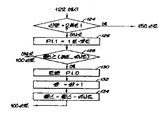
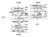
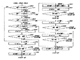
제7(a)-7(e)도는 제5도의 신호 처리 유니트에 의해 수생되는 신호 처리 알고리즘의 논리 흐름도.7 (a) -7 (e) are logic flow diagrams of a signal processing algorithm generated by the signal processing unit of FIG.
* 도면의 주요부분에 대한 부호의 설명* Explanation of symbols for main parts of the drawings
10 : 종자 감지기 14 : 종자 유통로10: seed detector 14: seed distribution channel
30 : 측판 38,40 : 유리창30:
39,45 : 슬로트 46,48 : 검출기39,45
52 : A/D 변환기 54 : 마이크로프로세서52: A / D converter 54: microprocessor
본 발명은 종자파종기에서 유통로를 흐르는 종자같은 입자를 감지하고 계수하기 위한 입자 계수기나 감지기에 관한 것이다.The present invention relates to a particle counter or detector for detecting and counting particles such as seeds flowing in a flow path in a seed seeder.
종자가 방사선이나 광의 빔(light beam)을 차단하는 광학 종자감지기는 알려져 있다. 이러한 시스템은 미국특허 제 4163507(벨), 357091(쉔켄베르그), 392851(파타우에르), 3723989(파다우에르 등), 4166948(스테펀), 3974377(스테펀), 4246469(멜로)에 기재되어 있다. 여러가지 이유때문에 이러한 종자 감지기는 부정확하다. 광원 및 광 검출기의 공간적 불균일성의 문제가 있어왔으며 광 검출기에 의해 발생된 신호는 광의 어느 부분이 차단되는지에 따라 변화된다. 다른 문제는 이러한 감지기가 미국특허 제 4163507호의 미분회로 같은 회로에 접속되며 이것은 검출기 출력단에서 실제적으로 펄스를 계수하는데 이러한 시스템은 광을 동시에 횡단 하는 복수의 종자를 한개로 계수한다는 것이다.Optical seed detectors are known in which seeds block radiation or light beams. Such a system is described in U.S. Pat. It is. These seed detectors are inaccurate for a variety of reasons. There has been a problem of spatial non-uniformity of the light source and the light detector and the signal generated by the light detector changes depending on which part of the light is blocked. Another problem is that such a detector is connected to a circuit, such as the differential circuit of US Pat. No. 4,163,507, which actually counts pulses at the detector output, such that the system counts multiple seeds that traverse light simultaneously.
본 발명의 목적은 도관을 통과하는 종자같은 소입자을 정확하게 계수하는 감지기를 제공하는 것이다.It is an object of the present invention to provide a detector that accurately counts small particles, such as seeds, that pass through a conduit.
본 발명의 다른 목적은 감지기를 동시에 통과하는 한개 그룹의 다수의 종자를 복수로 감지하고 계수할 수 있는 입자 혹은 종자 감지기를 제공하는 것이다.Another object of the present invention is to provide a particle or seed detector capable of sensing and counting a plurality of seeds in a group which simultaneously pass through the detector.
본 발명의 다른 목적은 종자가 감지기를 횡단할 때 그들의 위치에 관계없이 종자에 대해 균일하게 응답하는 감지기를 제공하는 것이다.Another object of the present invention is to provide a detector that responds uniformly to the seed when the seed traverses the detector, regardless of their position.
본 발명의 다른 목적은 파종기 종자 계측기의 테스트에 사용하는 입자의 시간 간격을 결정하는 것이다.Another object of the present invention is to determine the time interval of the particles used for the testing of the seed drill seed meter.
이러한 목적은 종자 도는 입자 도관의 한쪽을 횡단하여 연장된 적외선 LED어레이(array)를 포함하는 본 발명에 의해 성취된다. 이 어레이는 도관의 반대측에 연장되는 2차원의 포토다이오드에 의해 검출되는 실제적으로 균일하게 분산되는 방사 빔을 발생시킨다. 서로 마주보는 한쌍의 거울은 어레이와 포토다이오드 사이로 뻗어 있어서 도관내로 LED방사를 반사한다. 어레이와 도관 사이의 슬리트와 도관 및 포토다이오드 사이의 슬리트는 입자를 횡단하는 빔을 좁게하고 여분의 방사 빔이 포토다이오드에 충돌하는 것을 방지한다.This object is achieved by the present invention comprising an infrared LED array extending across one side of the seed or particle conduit. This array generates a substantially uniformly distributed radiation beam detected by a two-dimensional photodiode extending on the opposite side of the conduit. A pair of mirrors facing each other extends between the array and the photodiode to reflect the LED radiation into the conduit. The slits between the array and the conduits and the slits between the conduits and the photodiodes narrow the beam across the particles and prevent extra radiation beams from colliding with the photodiodes.
LED어레이에 의해 발생된 균일하고 연장된 방사 빔이 분산함에 따라, 복수의 입자가 단단히 붙어 있을 때나, 복수의 입자가 빔을 동시에 통과할 때나, 한개의 입자가 어레이와 입자 사이에 공간적인 "그림자"로 나타날때도 검출기를 통과하는 모든 통과입자는 포토다이오드에 의해 수신된 방사량에 대해 거의 동일한 결과를 갖는다. 포토다이오드의 신호는 포토다이오드에 비치는 방사의 총량에 대해 선형적인 관계를 가지며, 또한 검출기의 내부에서 빔을 차단하는 입자의 양에도 동일한 관계를 갖는다.As the uniform, elongated radiation beam generated by the LED array is dispersed, when a plurality of particles are firmly attached, or when a plurality of particles pass through the beam simultaneously, one particle is a spatial "shadow" between the array and the particles. All passing particles passing through the detector, even when indicated by ", have almost the same results for the radiation received by the photodiode. The signal of the photodiode has a linear relationship to the total amount of radiation reflected on the photodiode, and also to the amount of particles blocking the beam inside the detector.
포토다이오드의 신호는 전류전압 변환기, A/D변환기 및 마이크로프로세서를 포함하는 전자장치에 의해 처리된다. 마이크로프로세서는 포토다이오드의 신호에서 유래된 값을 반복적으로 적분하여, 빔을 통하는 입자를 정확하게 계수하는 연산을 수행한다. 이 연산은 빔을 통하여 전송되는 입자가 없을때 포토 다이오드에 의해 발생된 안정상태 신호에서의 변화를 보상하며, 빔을 동시에 통과하는 한 군의 입자에서 입자의 수를 결정한다. 이 연산은 평균입자크기에 있어서 단계적 변화를 보상한다.The signal of the photodiode is processed by an electronic device including a current voltage converter, an A / D converter and a microprocessor. The microprocessor iteratively integrates the values derived from the signal of the photodiode to perform an operation that accurately counts the particles through the beam. This operation compensates for changes in the steady state signal generated by the photodiode when no particles are transmitted through the beam and determines the number of particles in a group of particles that simultaneously pass through the beam. This operation compensates for the step change in average particle size.
종자 감지기(10)는 감지기 모듈(16)이 달린 종자 통로(14)를 형성하는 도간(12)을 포함한다. 감지기 모듈(16)은 종자통로(14)와 같이 형성된 각형 개구(22),(24)를 갖는 상부(18)와 베이스(20)를 포함한다.The
감지기 모듈(16)은 불투명 끝판(26),(28)(제2도참조)불투명 측판(side plate)(30),(32), 거울(34),(36), 유리창(38),(40) 상부(18) 및 베이스(20)의 내면상의 모든 홈 등을 포함한다.The detector module 16 comprises opaque end plates 26, 28 (see FIG. 2),
측판(30)은 방사선 발생기(CR1-CR7)의 어레이(42)(최소한 3개, 바람직하게는 7개)를 지지한다. 다양한 방사선 방출 장치가 사용될 수 있지만, 적외선 발생기는 적외선의 먼지 투과성 때문에 더욱 바람직하다. 적절한 장치는 지멘스의 SFH 407-3 GaAs적외선 발광 다이오드(LED)이다. 바람직하게, 판(30)은 여기에 장착된 LED(CR1-CR7)와 전기적으로 접속되기 위한 도전띠를 가진 인쇄회로 기판이다.The
제2도에 잘 나타나 있듯이, LED의 어레이는 종자 유통로(14)의 전 길이에 걸쳐 연장되어 있고 제1도에서 하측으로 보이는 종자유통방향에 횡렬로 연장된다. 각 LED에 의해 발생된 방사 빔은 평면상에 장착된 점광원에 접근하여 넓은 각으로 분산된다. 따라서, LED로부터의 인접 빔은 가장 가까운 창(38)에 도달하기 전에 서로 교차한다. 이것은 창(38),(40)사이의 종자 유통로에서의 모든 지역을 확실히 비춘다.As well shown in FIG. 2, the array of LEDs extends over the entire length of the seed flow path 14 and extends in a row in the seed flow direction seen downward in FIG. The radiation beam generated by each LED is distributed at a wide angle by approaching a point light source mounted on a plane. Thus, adjacent beams from the LEDs cross each other before reaching the
끝판(32)은 불투명 흑색 플라스틱으로 되어 있고 평면 2차원 검출기나 포토다이오드(46),(48)를 수신하는 각형 홈(44)을 가지며 이에 의해 수신된 방사 빔에 응답하여 전기신호를 발생한다. 끝판(32)은 감지될 전형적인 입자의 크기보다 적은 폭을 갖는 (바람직하게는 1mm폭) 수직 슬로트 혹은 구멍(45)을 포함한다. 따라서, 슬로트(45)는 LED어레이(42)의 방사선의 부분만이 검출기(46),(48)에 충돌하도록 허용한다. 슬로트(45)는 검출기(46),(48)상에 충돌하는 (다른 어레이로부터)인접 방사선의 양을 감소시킨다. 유리창(38)에 있는 슬로트(39)는 거울(34),(36) 및 유리창(38),(40)에 의해 둘러싸인 양의 외측에 있는 입자가 반사되는 것을 방지하기 위해 빔(3)의 분산각을 좁힌다.The
어레이(42)에 의해 발생되는 방사선에 응답하는데는 아무 검출기나 적합하다. 하지만 적외선 LED가 사용되는 경우에는 센트로닉 상사에서 제조한 SP-652와 같은 포토다이오드가 적합하다. 끝판(32) 및 포토다이오드(46),(48)는 서로 평행으로 배치되며 어레이(42)로부터 분리되어 종자 유통로(14)를 통해 이동하는 종자는 어레이(42)와 포토다이오드(46),(48)사이를 통과해야 하며 따라서 그에 의해 수신 방사선의 양이 변한다. 포토다이오드(46),(48)는 각형 구멍(22),(24)의 더큰 크기에 걸쳐서 있는 유통로를 횡단하여 연장된 2차원 방사 검출기를 형성한다.Any detector is suitable for responding to radiation generated by the
방사선 반사거울(34),(36)은 종자 유통로의 대향측에서 서로 평행으로 배치되어 있다. 거울은 측판(30)의 모서리부터 측판(32)의 모서리까지 연장되어 있다. 거울(34),(36)은 바람직하게 종자 유통로로부터 떨어진 면에서 은(silver) 혹은 반사체 코팅이 되어 있어서 반사체 코팅은 종자와의 마찰접촉에 의해 손상을 입지 않는다.The radiation reflection mirrors 34 and 36 are arranged in parallel with each other on the opposite side of the seed flow path. The mirror extends from the edge of the
제2도에서 보면, 종자에 의해 횡단하는 통로를 향하는 LED(CR1∼CR7)의 방사선은 거울(34),(36)에 의해 종자유통로에 반사된다. 이것은 거울(34),(36)의 평면에 미치지 못하는 어레이(42)를 갖는 것과 유사한 결과를 갖는다. 어레이(42), 거울(34),(36)은 어레이(42)에 가까운 종자의 그림자에 있는 종자를, 즉 뒤에 있는 것으로 보이는 종자를 검출 하도록 현재의 검출기를 가동시키는 분사된고, 균일하며 실제적으로 연장된 방사 빔을 형성하기 위하여 협동한다.In FIG. 2, the radiation of the LEDs CR1 to CR7 directed to the passage traversed by the seeds is reflected by the
유리창(38)은 LED 어레이(42)에 대하여 평행으로 떨어져 있고 방사된 적외선에 대해 투과성이 있으며 그에 의하여 도관(12)의 내벽(50)에 정렬되어 있는 내부 대향면을 갖는다. 유리창(38)은 거울(34)에서 거울(36)까지 연장되어 있다. 제1도 및 4도에서 볼 수 있듯이, 유리창(38)은 LED어레이(42)인접면에 불투명 코팅 혹은 마스크(37)를 가진다. 마스크(37)에서의 세로갭(39)은 약 1mm폭의 슬리트 구멍을 형성하며, 이것은 어레이(42)의 방사선이 통과한다. 갭(39)은 거울(34),(36) 사이에서 창(38)의 전 길이까지 연장된다.The
창(40)은 종자 유통로(14)의 반대편에서 창(38)과 평행으로 설치된다. 투명유리창(40)은 종자 유통로(14)에서 떨어진 채 대면한 방사 블로킹 불투명 마스크(41)를 갖는다. 마스크(41)의 세로갭(43)은 약 2mm의 폭을 가지며 LED어레이(42)의 방사선이 통과한다. 갭(43)은 거울(34),(36)사이의 유리창(40)의 전 길이에 걸쳐 연장된다.The
제5도에서 볼 수 있듯이, 각 LED(CR1∼CR7)은 대응저항(R1∼R7)에 직렬 접속되며 저항/LED 쌍은 +5 볼트의 전원에 병렬 접속된다. 2개의 검출기(46),(48)는 전기적으로 병렬 연결되어 있다. 제2도에서 볼 수 있듯이, 저항(R1∼R7)은 거울(34),(36)과 끝(end plate)(28),(26)사이의 공간에 위치한다. 검출기(46),(48)의 전류 신호는 전류-전압증폭기(50)에 의해 증폭된다. 바람직하게 증폭기(50)는 연산 증폭기(RCA의 CA3160)와 44pf의 쿠환 캐패시터(C1) 및 562KΩ의 궤환저항을 포함한다. 증폭기(50)는 아날로그 전압을 종래의 아날로그 디지탈 변환기(52)의 Vin입력단에 제공한다(예를들면 내쇼날 반도체 AD0820). A/D변환기(52)는 8비트 디지탈 신호(Vin에 나타나는 전압)를 마이크로프로세서(54)(예로써 인텔 8051)의 입력 P0.0내지 P0.7에 제공 한다. A/D변환기(52)는 그의 입력단 WR/RDY에서 수신된 플랙 신호에 응답하여 A-D변환을 시작한다.As can be seen in FIG. 5, each of the LEDs CR1 to CR7 is connected in series to the corresponding resistors R1 to R7 and the resistor / LED pair is connected in parallel to a power supply of +5 volts. The two
마이크로프로세서(54)(이하 마이크로라함)는 수정 발진기(56)로부터 12MHz의 주파수를 제공받는다. 이 주파수는 1mHz기계 명령 부파수를 제공하기 위하여 내부적으로 분주된다. 마이크로(54)내에 타이머(도시되지 않음)는 머신 사이클 주파수를 계수하고 100마이크로 초마다 플랙 신호를 발생한다.Microprocessor 54 (hereinafter referred to as micro) is provided with a frequency of 12 MHz from crystal oscillator 56. This frequency is internally divided to provide a 1 mHz machine command frequency. A timer (not shown) in micro 54 counts the machine cycle frequency and generates a flag signal every 100 microseconds.
마이크로(54)는 변환기(52)에 의해 새로운 AD변환이 실행되게 하며 플랙 신호의 발생에 응답하여 100마이크로 초마다 연산 혹은 명령셋트를 수행한다.The micro 54 causes a new AD conversion to be performed by the converter 52 and performs an operation or instruction set every 100 micro seconds in response to the generation of the flag signal.
마이크로(54)에 의해 수행되는 연산 혹은 프로그램은 제6도의 신호 타이밍 다이어그램과, 제7(a) 내지 7(e)도의 논리 흐름도를 참조하여 이해할 수 있다.The operation or program performed by the micro 54 can be understood with reference to the signal timing diagram of FIG. 6 and the logic flow diagrams of FIGS. 7 (a) to 7 (e).
제6도로 돌아가서, 상부의 파형은 볼 베어링 같은 입자가 검출기(10)를 통과할때 A/D변환기(52)의 Vin에서의 전압의 전형적인 오실로스코프 파형이다. 60,68 및 70에서의 신호펄스는 검출기(10)를 통하여 흐르는 단일 입자에 의해 발생되는 신호이다. 64, 66, 74 및 76에서의 신호펄스는 2개의 입자가 검출기(10)를 통과할 때의 표시이다. 펄스(74)는 2개의 입자가 연속하여 바로 통과할 때 발생된다. 펄스(64)는 제1입자가 떠나기 전에 제2입자가 방사 빔으로 들어갈 때 발생된다. 펄스(64) 및 (66)는 2개의 입자가 동시에 검출기를 통과하거나, 혹은 서로 매우 인접해 있는 경우를 입자군의 방향에 관계없이 나타낸다. 펄스(62)는 검출기(10)를 3개의 입자가 거의 동시에 통과할 때 발생된다. 펄스(72)는 검출기(10)를 4개의 입자가 거의 동시에 통과할 때 발생된다. 파형내의 괄호번호는 임의의 유니트에서 펄스에 의해 구획된 부분에 비례한다. 이들 파형을 각각에 의해 구획된 구분이 파형을 발생하는 입자의 수에 관계됨을 도시한다.Returning to FIG. 6, the upper waveform is a typical oscilloscope waveform of the voltage at Vin of the A / D converter 52 as particles such as ball bearings pass through the
미분형 계수기는 펄스(62),(64),(66) 및 (72)를 입자 1, 1, 2 혹은 3, 및 4개에 의해 발생된 것으로 부정확하게 설명하며 이들 펄스는 3, 2, 3 및 4입자의 군에 의해 실제적으로 발생되는 것과 같다. 다음의 신호처리연산은 3, 2, 2 및 4의 입자 계수에 의해 발생된 펄스를 정확하게 설명한다.The differential counter incorrectly describes
제7(a) 내지 7(e)도에 돌아가서, 연산은 감지기를 한개의 입자가 통과함에 의해 생기는 신호펄스에 의해 구획된 전형적인 부분의 초기산정을 나타내기 위해 처음에 768과 동일한 UNIT갑의 1/2과 동일한 HALF UNIT의 셋팅에 의해 단계(100)에서 시작한다. 그런 펄스는 제6도의 60으로 도시된다. 그러면, 다나계(102)는 100마이크로 초 간격으로 내부 타이머가 플랙 신호를 발생시킬 때까지 연산을 정지하도록 한다. 플랙 신호의 발생에서, 단계(104)는 A/D변환기(52)가 변환을 수행하도록 하며, 마이크로(54)에 새로운 디지탈 Vin값(INPUT)을 입력시킨다.Returning to Figs. 7 (a) to 7 (e), the calculation is initially performed in units of UNIT equal to 768 to represent an initial estimate of the typical part partitioned by a signal pulse generated by the passage of a single particle through the detector. Begin at
그러면, 단계(106)에서, SIGNAL 값은 OFFSET-INPUT과 동일하게 셋트되며, 이때 OFFSET는 종자가 빔 B를 차단하지 않을 때 Vin(정상적으로 4볼트)의 정상상태를 천천히 변화시킴을 나타낸다. 따라서, 종자가 빔 B에 있을 때, SIGNAL값은 정극성이며, 빔 B에 종자가 없을때 Vin의 정상상태 값에 관련된 각 샘플링 순간에서의 Vin신호(제6도)의 수직 깊이를 나타낸다.Then, at step 106, the SIGNAL value is set equal to OFFSET-INPUT, where OFFSET indicates slowly changing the steady state of Vin (normally 4 volts) when the seed does not block beam B. Thus, when the seed is in beam B, the SIGNAL value is positive and represents the vertical depth of the Vin signal (FIG. 6) at each sampling instant relative to the steady state value of Vin when there is no seed in beam B.
하지만 SIGNAL은 종자가 없을 때 및 OFFSET값이 전류 정상상태 Vi의 레벨보다 낮으면 부극성이다. 이 경우에, 단계(108)는 연산이 단계(136 내지 1144)로 한다. 단계(136)에서, DNTIME 타이머는 12msec 간격을 나타내는 값을 초기화 시킨다.However, SIGNAL is negative when there is no seed and when the OFFSET value is below the level of the current steady state Vi. In this case, step 108 causes the operation to be steps 136-1144. In
단계(138)는 UPTIME타이머를 감소시킨다. 단계(140)는 UPTIME타이머가 계수되지 않았다면 단계(150)에 연산을 순환시킨다. 그렇지 않으면, 단계(142)에서, OFFSET값이 하나의 2진 수 만큼 증가한다. 최종적으로 단계(144)는 UPTIME 타이머를 3msec값이 셋트시킨다. 따라서, OFFSET값은 SIGNAL값이 3msec이상 부극성으로 존재하면 증가하게 된다.Step 138 decreases the UPTIME timer. Step 140 cycles the operation to step 150 if the UPTIME timer has not been counted. Otherwise, in step 142, the OFFSET value is increased by one binary number. Finally, step 144 sets the UPTIME timer to 3msec. Therefore, OFFSET value increases when SIGNAL value is negative for more than 3msec.
SIGNAL이 부극성이 아니면, 단계(108)는 SIGNAL=0인지를 결정하는 단계(110)에 연산을 지시한다. 답이 예 이면, 종자가 없다는 뜻이며, 전류 OFFSET값을 적절하게 나타나고 단계(146),(148)는 UPTIME과 DNTIME 타이머가 3msec를 나타내는 값을 갖도록 셋트된다. 아니오 이면, 종자가 빔 B에 있다는 뜻이다.If SIGNAL is not negative, step 108 directs the operation to step 110 to determine if SIGNAL = 0. If the answer is yes, then there is no seed, the current OFFSET value appears appropriately and steps 146 and 148 are set such that the UPTIME and DNTIME timers have a value representing 3 msec. No means that the seed is in beam B.
단계(112)에서, UPTIME 타이머는 3msec값으로 셋트되다. DNTIME 타이머는 단계(114)에서 감소한다. 그러면, 단계(116)는 DNTIME타이머 값이 0보다 큰가를 결정한다. 아니오이면 SIGANAL은 12msec 동안 정극성 이었으며 OFFSET값은 단계(118)에서 1디지탈 계수 만큼 조정되고, DNTIME타이머는 12msec를 나타내는 값으로 다시 셋트된다. 단계(116)에서, DNTIME계수기가 0보다 크면(이것은 12msec보다 짧게 SIGNAL이 정극성 이었음을 의미함) 혹은, 단계(120)후에 연산은 단계(122)로 진행한다.In
단계(122)에서, PULSE값(초기 영)은 그의 초기 값에 전류 SIGNAL값을 부가하여 숫자적으로 증분시킨다. 따라서, PULSE값은 제6도에 도시된 Vin신호펄스이 도형 표시에 의해 구획된 부분을 나타낸다.In
단계(124)는 SIGNAL이 1혹은 2의 디지탈 계수와 동일함을 결정한다. 그렇지 않으면 SIGNAL이 부극성이 아니거나 영이 아님을 단계(108) 및 (110)가 이미 결정했기에 SIGNAL은 2보다 더 커져야 한다. 이 경우에, 종자는 빔 B를 통과 하거나 그에 남아 있으며 연산은 P1.1플래그(초기 영)가 1로 셋트된느 스텝(126)으로 넘어간다. 그러면, 단계(128)는 영역 값 펄스 PULSE가 HALF UNIT값과 같거나 크게됨을 결정한다(이것은 단일 종자의 통과에 의해 발생되는 단일 펄스의 전형적인 면적을 50%를 나타낸다). PULSE가 상기 50% 영역값을 얻지 못하면, 연산은 단계(106)에서 SINGAL값의 업데이트를 위하여 또, 단계(122)에서 PULSE값의 집적화를 위해 단계(100)로 돌아간다. 하지만 PULSE가 50%영역 값을 초과하면 단계(130)는 마이크로 출력 포트 P1.0에서의 신호가 감지기를 통하여 종자의 통과를 표시하도록 토글된다. 다음에, 단계(132)는 감지기를 통과하는 종자의 수를 표시하는 QUAN 값(초기 영)을 증분시킨다. 그러면, 단계(134)는 영역값, PULSE를 (PULSE-UNIT)와 동일하게 셋트시키며 연산을 단계(100)로 귀환시킨다. 이것은 PULSE 값을 부극성으로 만들어 단계(128)의 상태가 종자의 통과에 기인하여 단계(122)에 의해 PULSE 값의 반복 집적을 부가하게 된다.Step 124 determines that SIGNAL is equal to one or two digital coefficients. Otherwise SIGNAL should be greater than 2 since steps 108 and 110 have already determined that SIGNAL is not negative or non-zero. In this case, the seed passes through or remains on beam B and the operation proceeds to step 126 where the P1.1 flag (initial zero) is set to one. Step 128 then determines that the area value pulse PULSE is equal to or greater than the HALF UNIT value (this represents 50% of the typical area of a single pulse generated by the passage of a single seed). If PULSE does not obtain the 50% region value, the operation returns to step 100 for updating the SINGAL value in step 106 and for the integration of the PULSE value in
단계(124)에서, SIGNAL 값이 2 혹은 1의 디지탈 값을 가지면, 빔 B를 통하는 종자의 유통은 방금 시작하거나 곧 종료됨(잡음이나 바이어스 레벨의 부극성 드리프트가 발생됨)을 의미하며 연산은 단계(150)로 진행하며, PULSE 값의 집적화가 금지된다. 단계(150)는 P1.1 플래그값(초기 영)이 1과 같음을 결정한다. P1.1가 1이 아니면, 단계(126)는 아직 수행되지 않으며, 그 이유는 최종 종자가 끝나는 단계(151)에서 P1.1가 영으로 되고 종자가 통과중인 증거(즉 SIGNAL 2)가 있기 때문이다. 이 경우에, 연산은 PULSE 및 Quan 값이 비워지고 연산이 단계(100)로 가는 단계(208 내지 212)를 향하게 된다.In step 124, if the SIGNAL value has a digital value of 2 or 1, the distribution of the seed through beam B just starts or ends soon (negative drift of noise or bias level occurs) and the operation is Proceeding to 150, integration of the PULSE value is prohibited. Step 150 determines that the P1.1 flag value (initial zero) is equal to one. If P1.1 is not 1, step 126 is not yet performed because at step 151 where the final seed ends, P1.1 becomes zero and there is evidence that the seed is passing (ie SIGNAL 2). to be. In this case, the operation is directed to steps 208-212 where the PULSE and Quan values are empty and the operation goes to step 100.
반면에, 만약 P1.1값이 단계(150)에서 1과 같으면, 이것은 종자 전송이 방급 종료되고 연산은 P1.1가 비워지는 단계(151)로 감을 의미한다.On the other hand, if the P1.1 value is equal to 1 in
단계(152)에서 영역 값'[]LSE가 HALF-UNIT 영역과 비교된다. PULSE가 HALF-UNIT 보다 적으면 연산은 단계(106)으로 진행한다. 하지만, PULSE가 HALT-UNIT 보다 적지 않으면, 단계(154)는 마이크로 출력 포트 P1.0가 감지기를 통과하는 종자의 전송을 표시하도록 토글(단계 (130)에서)하게 한다. 그러면, 전체 종자 갯수 QUAN은 단계(156)에서 증가하며, PULSE값은 단계(158)에서 부극성 값으로 리셋트된다(단계(134)에서와 같이).In
여기에서, 단일 종자가 빔 B를 통과할때 값 PULSE가 어떻게 변화하는지를 이해하기 쉽다. 처음에는, PULSE 값이 영이 된다. 그리고 종자가 통과함에 따라 제6도의 60과 같은 파형이 생기며, PULSE 값은 HALF-UNIT 값과 동일해질때까지 단계(122)에서 증가 SIGNAL의 부가에 의해 반복적으로 증가되며, 이때에 Vin 레벨은 최소가 되고 SIGNAL 값은 최대가 된다. 단계(128)는 단계(130 내지 134)를 통하여 연산을 지시하도록 작동하며, UNIT 값이 처리되는 파형 펄스에 의해 둘러싸인 영역을 정확히 나타낸다면 단계(134)는 전형적으로 V(HALF-UNIT)와 동일한 부극성 값으로 PULSE 값을 리셋트한다.Here, it is easy to understand how the value PULSE changes when a single seed passes through beam B. Initially, the PULSE value is zero. As the seed passes, a waveform such as 60 in FIG. 6 is generated, and the PULSE value is repeatedly increased by the addition of increasing SIGNAL in
그러면 파형(60)의 두번째 반주기 동안에, 단계(122)은 PULSE 값을 적분하여 Vin이 그의 정상상태로 돌아올때 및 SIGNAL이 영으로 될대 PULSE 값이 영으로 되며 UNIT 값은 펄스 파형(60)의 전체부분의 정확한 산정값으로 가정된다.Then, during the second half period of waveform 60,
이제 사실 산정된 영역 값 UNIT가 너무 크다면, 종자 전송의 끝부분에서 단계(122)의 PULSE값은 약간 부극성이 된다.Now if the estimated area value UNIT is too large, the PULSE value of
따라서 후에 자세히 기술되듯히, 이 약간의 부극성 PULSE 값은 TOTAL 값을 약간 감소시키도록 연산부분(180)에 사용된다.Thus, as will be described in detail later, this slight negative PULSE value is used in
TOTAL 값이 3 바이트 값(각 바이트 8비트)으로 기억되면, 정의에 의해 UNIT 값은 TOTAL의 2개의 최상위 바이트에 기억되며, TOTAL 값의 감소는 UNIT 값을 감소시키며, 따라서 UNIT 값을 단일 종자의 통과에 의해 발생된 평균 평균신호펄스에 거의 가깝게 만든다. 마찬가지로, 산정된 영역 값인 UNIT가 너무 작다면 단계(122)에서의 PULSE 값(펄스 영역 적분의 끝에서)은 약간 정극성이 된다. 이것은 연산 부분(180)이 TOTAL 값을 약간 증가시키도록 하며, 다음 종자 통과시에 사용하는 UNIT 값을 대응 증가시킨다. 따라서, TOTAL과 UNIT 값을 조정하여, 연산은 감지기를 통과하는 종자의 평균크기에 있어서의 변화를 자동적으로 보상한다.If the TOTAL value is stored as a 3 byte value (8 bytes each byte), by definition the UNIT value is stored in the two most significant bytes of the TOTAL, and decreasing the TOTAL value reduces the UNIT value, thus converting the UNIT value into a single seed. It approximates the average average signal pulse generated by the pass. Likewise, if the calculated area value UNIT is too small, the PULSE value (at the end of the pulse area integration) at
다음은 단계(160 내지 210)에 대해 기술한다. 요약하면 단계(160 내지 210)는 산정된 신호펄스 부분 값인 UNIT에서 주조정(필요하다면)을 하여 UNIT 및 HALF-UNIT의 정확한 값이 단계(100)(128)(134)(152) 및 (158)에서 사용되게 한다.The following describes steps 160-210. In summary, steps 160 to 210 are made by main adjustment (if necessary) in the calculated signal pulse fraction value UNIT so that the correct values of UNIT and HALF-UNIT are obtained in
단계(160 내지 166)는 QUAN 값(단계(132) 혹은 (156)에서 영 혹은 세트된)이 0,1,2,3 혹은 그 이상과 같음을 결정한다(1 종자 QUAN=0)보다 적은 것의 통과에 의해 생기는 표시 신호펄스 혹은 1,2,3 혹은 그 이상의 종자에 의해 생기는 펄스).
정상상태에서, 가장 자주 발생되는 신호 펄스는 빔 B를 통과하는 단일 입자 또는 종자 전송에 의해 발생되는 것이며, 따라서 QUAN은 대부분 1과 동일하다(적절히 정확한 UNIT 값으로 가정). 이 경우에, 단계(162)는 현재 TOTAL과 나머지 PULSE 값의 합과 동일한 업 데이트된 TOTAL 값을 유도하는 효과를 갖는 180으로 표시되는 연산 부분에 상기 연산을 순회시킨다. 따라서 상술한 바와같이 TOTAL값은 UNIT값에 관계되며, 이 경우에 UNIT 값을 반복적으로 조절하여 단일 입자의 전송에 의해 발생된 신호 펄스영역의 표시가 계속되게 한다. 그러면, 단계(182)는 ONES 계수기를 감소시킨다.In steady state, the most frequently generated signal pulses are those generated by a single particle or seed transmission through beam B, so QUAN is mostly equal to 1 (assuming a reasonably accurate UNIT value). In this case, step 162 iterates the operation to the operation portion indicated by 180 which has the effect of deriving an updated TOTAL value equal to the sum of the current TOTAL and the remaining PULSE values. Thus, as described above, the TOTAL value is related to the UNIT value. In this case, the UNIT value is repeatedly adjusted so that the display of the signal pulse region generated by the transmission of a single particle is continued. Step 182 then decreases the ONES counter.
(단계 (200)에서 초기 256 혹은 256으로 리셋트함). ONES 계수기가 영으로 감소하면 단계(184)는 이 초과상태를 인식하며, ZEROES, ONES TWOS, THREES 및 FOURS계수기를 256으로 리셋트 시키는 단계(198-210)로 연산을 순회시키며 또한 이것은 PULSE 및 QUAN 값을 영으로 크리어하여 단계(100 내지 158)에 의해 그것들은 결정될 수 있다. ONES 계수기가 초과되지 않으면, 연산은 단계(184)에 의해 단계(208) 및 (210)으로 넘어간다.(Reset to initial 256 or 256 at step 200). If the ONES counter is decremented to zero, step 184 recognizes this excess condition and iterates the operation to steps 198-210 to reset the ZEROES, ONES TWOS, THREES and FOURS counters to 256, which is also PULSE and QUAN. By clearing the values to zero they can be determined by steps 100-158. If the ONES counter is not exceeded, the operation proceeds to step 208 and 210 by step 184.
따라서, UNIT 값이 산정된 단일 종자 펄스 부분을 정확히 표시하면, 연산은 UNIT 값을 자주 조정하며(180에서 TOTAL 값의 조정을 통하여), 계속적으로 ZEROS, TWOS, THREES, FOURS 계수기를 단계(198)(202)(204) 및 (206)에서 리셋트시켜서 연산이 그에 의한 TOTAL을 2로 분주하거나 TOTAL을 2로 채배하는 단계(178) 또는 단계(172)를 수행하지 않게 한다.Thus, if the UNIT value accurately represents a single seed pulse portion, the operation adjusts the UNIT value frequently (through adjustment of the TOTAL value at 180), and continuously the ZEROS, TWOS, THREES, and FOURS counters (198). Reset at 202, 204 and 206 so that the operation does not perform step 178 or step 172 by dividing the TOTAL by two or by dividing the TOTAL by two.
하지만 UNIT 값이 너무 크면 QUAN 값은 단계(128)(152)가 단계(132)(156)에서의 QUAN 값의 증가를 방해하므로 종종 영이 된다. 이 경우에, 연산은 ZEROS 계수기를 감소시키는 단계(174) 내지 단계(160)에 의해 지시된다. 이 상황이 계속되면 단계(174)는 마침내 ZEROES 계수기를 영으로 감소시키고, 단계(176)는 오버플로우 상태를 인식하고 연산을 단계(178)로 순환시킨다. 단계(178)는 TOTAL 값을 50% 만큼(예를들어) 감소시키며, 따라서 UNIT 값에 대응감소를 초래한다.However, if the UNIT value is too large, the QUAN value is often zero since
결과적으로, 이 과정은 단일 종자 통과가 1과 같은 QUAN 값으로 만드는 레벨로 UNIT 값을 감소시킬 것이다.As a result, this process will reduce the UNIT value to the level at which a single seed pass makes a QUAN value equal to one.
산정된 펄스부분값 UNIT가 너무 낮으면, 최다발생 단일 종자 통과는 2,3 혹은 그 이상의 QUAN 값을 산출한다. 이경우에, 단계(164)(166)는 연산을 단계(186)(192) 혹은 (194)에 순환시키며 여기서 TWOS, THREES 및 FOURS 계수기(초기에 256 혹은 256으로 단계(202) 내지 (206)에서 리셋트시킴)가 감소된다. 이 계수기가 영이 되면, 단계(188),(194) 혹은 (170)는 오버플로우 상태를 인정하며, 연산을 단계(172)로 순환시킨다. 단계(172)는 TOTAL 값을 2만큼 증배하며, 따라서 산정 영역 UNIT의 증분을 발생시킨다.If the estimated pulse fraction value UNIT is too low, the most frequent single seed pass yields 2, 3 or more QUAN values. In this case, steps 164 and 166 cycle the operation to
그렇지 않으면 단계(188)(192) 및 (170)는 연산을 단계(208)(210)에 직접 순환시키며, 그래서 단계(100)에 돌아오게 한다.Otherwise steps 188,192 and 170 cycle the operation directly to
TWOS, THREES 혹은 FOURS 계수기의 값이 먼저 오버플로우에 관계없이 TOTAL 값(예를들면 단계(172)에서)을 2배하는 것은 적절하다. 하지만, 각 단계(188)(194) 및 (170)후에 분리된 TOTAL 재게산 단계를 첨가하여 먼저 오버플로우된 것을 계수함에 따라 다른 양으로 TOTAL 값을 변화시키는 것은 가능하다.It is appropriate that the value of the TWOS, THREES or FOURS counter first doubles the TOTAL value (eg in step 172) regardless of overflow. However, it is possible to add a separate TOTAL recalculation step after each
다른 대안은 단계(162)로부터 단계(186)까지 "NO"가지를 순화시키며 단계(164 내지 170) 및 단계(192 내지 194)제외), 초기치를 만들고 TWOS 계수기의 값보다 ONES계수기의 값을 더 작게 리셋트 시키며, 따라서 정상조건에서, ONES 계수기는 TWOS 계수기(이경우에, 2 혹은 그 이상의 QUAN 값을 발생시키는 종자의 전송에 의해 감소됨)전에 오버플로우되게 한다.Another alternative is to purify the "NO" branch from step 162 to step 186, except for steps 164 to 170 and
"발명의 상세한 설명"의 말미에 제7a-7e도의 논리흐름도에 의해 설명된 컴퓨터 프로그램의 오브젝트 및 소스 코드 목록이 수록된다. 소스 코드목록은 이흐름도에서 유사한 라벨에 대응하는 예를들면 READ : 및 ADDPULSE;, 등을 포함한다.At the end of the "Detailed Description of the Invention", a list of objects and source codes of the computer program described by the logic flow diagrams of FIGS. The source code listing includes, for example, READ: and ADDPULSE; corresponding to similar labels in this flowchart.
또한 이 흐름도와 프로그램 목록에 사용된 다양한 약어를 포함하는 세로 참조심볼 표가 첨부된다.Also attached is a vertical reference symbol table containing various abbreviations used in this flowchart and program listing.
본 발명이 특별한 실시예에 대하여만 기술된 반면에, 많은 대안과 수정 및 변형이 이 분야의 숙련자에게 용이하다는 것은 명백하다. 예를들면 여기에 기술된 신호처리 연산은 감지기가 종자의 수를 따라 선형적으로 변하는 신호를 발생할 수 있는 한 어떠한 형태의 종자 감지기에도 조합하여 사용될 수 있다. 따라서, 본 발명은 첨부된 청구 범위의 정신과 배경을 벗어나기 않는 범위에서 이러한 모든 대안, 소정 및 변형을 포함한다.While the present invention has been described with respect to particular embodiments only, it will be apparent that many alternatives, modifications and variations are readily available to those skilled in the art. For example, the signal processing operations described herein can be used in combination with any type of seed detector as long as the detector can generate a signal that varies linearly with the number of seeds. Accordingly, the present invention is intended to embrace all such alternatives, modifications and variations without departing from the spirit and background of the appended claims.
Claims (14)
Applications Claiming Priority (2)
| Application Number | Priority Date | Filing Date | Title |
|---|---|---|---|
| US06/649,098 US4634855A (en) | 1984-09-10 | 1984-09-10 | Photoelectric article sensor with facing reflectors |
| US649098 | 1996-05-17 |
Publications (2)
| Publication Number | Publication Date |
|---|---|
| KR860002770A KR860002770A (en) | 1986-04-28 |
| KR930003129B1 true KR930003129B1 (en) | 1993-04-19 |
Family
ID=24603461
Family Applications (1)
| Application Number | Title | Priority Date | Filing Date |
|---|---|---|---|
| KR1019850006571A KR930003129B1 (en) | 1984-09-10 | 1985-09-09 | Seed counter |
Country Status (11)
| Country | Link |
|---|---|
| US (1) | US4634855A (en) |
| EP (1) | EP0175530B1 (en) |
| JP (1) | JPS6170682A (en) |
| KR (1) | KR930003129B1 (en) |
| AT (1) | ATE58796T1 (en) |
| AU (1) | AU574503B2 (en) |
| CA (1) | CA1242015A (en) |
| DE (1) | DE3580733D1 (en) |
| IE (1) | IE56894B1 (en) |
| MX (1) | MX159097A (en) |
| ZA (1) | ZA856922B (en) |
Families Citing this family (27)
| Publication number | Priority date | Publication date | Assignee | Title |
|---|---|---|---|---|
| US5151591A (en) * | 1991-03-20 | 1992-09-29 | Honeywell Inc. | Asynchronous signal interrogation circuit for an detection apparatus |
| JPH0815449A (en) * | 1994-04-26 | 1996-01-19 | Omron Corp | Rain drop sensor and rain-drop measuring device using the sensor as well as wiper driving device using the measuring device |
| CA2141092C (en) * | 1995-01-25 | 1999-01-05 | James F. White | Communication between components of a machine |
| US5533458A (en) * | 1995-03-14 | 1996-07-09 | Deere & Company | Seed tube for an agricultural seeding machine |
| US5650609A (en) * | 1995-05-15 | 1997-07-22 | Phoenix International Corporation | Seed monitoring system for counting seeds as they are dispensed through a seed planting tube |
| GB2301787B (en) * | 1995-05-16 | 1999-11-10 | Semelab Plc | Separating and sequencing apparatus |
| CA2158894C (en) * | 1995-09-22 | 2001-12-11 | Rasvan N. Dragne | Seed counting apparatus for a planter monitor |
| US5969340A (en) * | 1995-09-22 | 1999-10-19 | Vansco Electronics Ltd. | Seed counting apparatus for a planter monitor |
| US6332413B1 (en) | 1995-12-29 | 2001-12-25 | Case Corporation | Seed tube for seed metering apparatus |
| US6564730B2 (en) | 1995-12-29 | 2003-05-20 | Case Corporation | Seed planter apparatus and method |
| US6109193A (en) | 1995-12-29 | 2000-08-29 | Case Corporation | Seed planter apparatus and method |
| US6044779A (en) * | 1998-04-15 | 2000-04-04 | Case Corporation | Multiple drop seed disc |
| US6373057B1 (en) | 1998-09-23 | 2002-04-16 | Dickey-John Corporation | Infrared reflective article counting/detecting device |
| US7286901B2 (en) * | 2001-02-27 | 2007-10-23 | Crane Co. | Method and system for accomplishing product detection |
| US6732014B2 (en) * | 2001-02-27 | 2004-05-04 | Crane Co. | System for accomplishing product detection |
| US8548625B2 (en) * | 2001-08-23 | 2013-10-01 | Crane Merchandising Systems, Inc. | Optical vend sensing system for product delivery detection |
| US7391898B2 (en) * | 2003-10-10 | 2008-06-24 | Nova Packaging Systems, Inc. | Method and apparatus for programmable zoned array counter |
| US7565222B2 (en) * | 2004-01-15 | 2009-07-21 | Fawn Engineering Corporation | Economical optical system to provide reasonable assurance of completed vend or vendible items from vending machines |
| DE102004008052B4 (en) * | 2004-02-19 | 2007-08-16 | Amazonen-Werke H. Dreyer Gmbh & Co. Kg | Device for optically counting small particles |
| SE0400933L (en) * | 2004-04-06 | 2005-03-01 | Vaederstad Verken Ab | Seed counting device and method of seed drill |
| CN102353553B (en) * | 2011-07-01 | 2014-05-28 | 中国农业大学 | Seed sowing device performance detection apparatus |
| EP2888614B1 (en) * | 2012-08-27 | 2017-04-12 | Dickey-John | Seed sensor with lightpipe photodetect assembly |
| SE537664C2 (en) * | 2014-01-27 | 2015-09-29 | Väderstad Verken Ab | Monitoring of feed of granules |
| EP3135090A1 (en) * | 2015-08-24 | 2017-03-01 | Digitroll Kft. | Seed sensor and method for detecting blockage of a seeding channel |
| IT201700086711A1 (en) * | 2017-07-28 | 2019-01-28 | M C Elettr S R L | SEEDER COUNTER DEVICE |
| JP2020006886A (en) * | 2018-07-11 | 2020-01-16 | 株式会社デンソー | Rainfall amount measurement device |
| US11620868B2 (en) | 2021-07-22 | 2023-04-04 | Trinity Axis Inc. | Techniques to dispense an item and release a jammed item from a dispensing system |
Family Cites Families (13)
| Publication number | Priority date | Publication date | Assignee | Title |
|---|---|---|---|---|
| US2803756A (en) * | 1948-12-13 | 1957-08-20 | Mandrel Industries | Viewing chamber for gravity sorter |
| GB1044552A (en) * | 1964-01-22 | 1966-10-05 | Decca Ltd | Improvements in or relating to photo-electric detecting devices |
| US3537091A (en) * | 1967-10-05 | 1970-10-27 | Case Co J I | Seed monitoring system |
| GB1298999A (en) * | 1970-02-26 | 1972-12-06 | Orbit Controls Ltd | Improvements in or relating to apparatus for detecting the passage of movable small bodies |
| US3648054A (en) * | 1970-06-12 | 1972-03-07 | Amf Inc | Article detecting and counting apparatus |
| US3928751A (en) * | 1971-08-19 | 1975-12-23 | Dickey John Corp | Seed population monitor |
| US3890221A (en) * | 1973-12-14 | 1975-06-17 | Sortex North America | Translucency/opaque sorting |
| JPS52151776U (en) * | 1976-05-13 | 1977-11-17 | ||
| US4096424A (en) * | 1976-07-12 | 1978-06-20 | N.D.T. Laboratories, Inc. | Electrical circuit for controlling the feed rate of parts |
| US4054779A (en) * | 1976-07-19 | 1977-10-18 | Lake Center Industries | Counting device |
| US4150286A (en) * | 1977-10-17 | 1979-04-17 | The Babcock & Wilcox Company | Material flow monitoring circuit |
| US4163507A (en) * | 1978-03-20 | 1979-08-07 | International Tapetronics Corporation | Optical seed sensor for a seed planter monitor |
| US4307390A (en) * | 1979-11-07 | 1981-12-22 | Dickey-John Corporation | Corn and soybean sensor |
-
1984
- 1984-09-10 US US06/649,098 patent/US4634855A/en not_active Expired - Lifetime
-
1985
- 1985-09-09 IE IE2218/85A patent/IE56894B1/en not_active IP Right Cessation
- 1985-09-09 JP JP60199304A patent/JPS6170682A/en active Granted
- 1985-09-09 AT AT85306373T patent/ATE58796T1/en active
- 1985-09-09 CA CA000490254A patent/CA1242015A/en not_active Expired
- 1985-09-09 EP EP85306373A patent/EP0175530B1/en not_active Expired - Lifetime
- 1985-09-09 DE DE8585306373T patent/DE3580733D1/en not_active Expired - Lifetime
- 1985-09-09 KR KR1019850006571A patent/KR930003129B1/en not_active IP Right Cessation
- 1985-09-10 AU AU47333/85A patent/AU574503B2/en not_active Ceased
- 1985-09-10 MX MX206579A patent/MX159097A/en unknown
- 1985-09-10 ZA ZA856922A patent/ZA856922B/en unknown
Also Published As
| Publication number | Publication date |
|---|---|
| JPS6170682A (en) | 1986-04-11 |
| EP0175530A2 (en) | 1986-03-26 |
| AU4733385A (en) | 1986-03-20 |
| IE852218L (en) | 1986-03-10 |
| ZA856922B (en) | 1987-05-27 |
| EP0175530A3 (en) | 1988-01-13 |
| MX159097A (en) | 1989-04-14 |
| DE3580733D1 (en) | 1991-01-10 |
| US4634855A (en) | 1987-01-06 |
| ATE58796T1 (en) | 1990-12-15 |
| AU574503B2 (en) | 1988-07-07 |
| EP0175530B1 (en) | 1990-11-28 |
| KR860002770A (en) | 1986-04-28 |
| CA1242015A (en) | 1988-09-13 |
| JPH0227711B2 (en) | 1990-06-19 |
| IE56894B1 (en) | 1992-01-15 |
Similar Documents
| Publication | Publication Date | Title |
|---|---|---|
| KR930003129B1 (en) | Seed counter | |
| KR920008276B1 (en) | Article or seed counter | |
| US5428215A (en) | Digital high angular resolution laser irradiation detector (HARLID) | |
| US4247767A (en) | Touch sensitive computer input device | |
| EP3340766B1 (en) | Seed counting sensor and method for detecting blockage of a seed conveying pipe | |
| EP0214348B1 (en) | High rate seed sensor | |
| JPS6019441B2 (en) | Detection circuit of photocell pattern sensing device | |
| US5911161A (en) | Apparatus and method for binocular measurement system | |
| KR102017257B1 (en) | Small-sized optical fine dust sensor capable of counting by particle size | |
| TW349011B (en) | Remote position sensing apparatus and method | |
| US4281325A (en) | Positive feedback meter pulse initiator | |
| US4755127A (en) | Apparatus for regulating the operation of a plant for the making of extruded products | |
| US4911307A (en) | Photoelectric apparatus for sorting articles according to size | |
| US5499094A (en) | Apparatus and method for measuring the length and width of a spot of light utilizing two different masks | |
| GB2267963A (en) | Obscuration sensor | |
| KR20180113341A (en) | Apparatus for sensing particle | |
| EP0629983A1 (en) | Obscuration type smoke detector | |
| Linsley | Some problems in measuring EAS particle density with scintillation detectors | |
| JP3898307B2 (en) | Photoresponsive particle concentration meter | |
| Kampert et al. | A high resolution BGO calorimeter with longitudinal segmentation | |
| Kurz et al. | One-and two-dimensional position sensitive scintillation detectors for thermal neutrons | |
| JPH02240515A (en) | Position detecting device | |
| SE509763C2 (en) | Optical distance meter | |
| CS207192B1 (en) | Connection of the detection unit of the ionizing radiatin with possibility of adjusting the fundamental sensitivness and linear impulse caracteristics | |
| HU191864B (en) | Detector unit for apparatus of x-ray diagnostic |
Legal Events
| Date | Code | Title | Description |
|---|---|---|---|
| A201 | Request for examination | ||
| E902 | Notification of reason for refusal | ||
| G160 | Decision to publish patent application | ||
| E701 | Decision to grant or registration of patent right | ||
| GRNT | Written decision to grant | ||
| FPAY | Annual fee payment |
Payment date: 20020330 Year of fee payment: 10 |
|
| LAPS | Lapse due to unpaid annual fee |